德国SCANLAB扫描振镜应用指南-产品手册 SCANLAB产品大全
振镜式激光标记机
1.1 激光标记系统国内外发展动态激光标记又称激光打标,是利用高能量密度的激光束对目标作用,使目标表面发生物理或化学的变化,从而获得可见图案的标记方式。
高能量的激光束聚焦在材料表面,使材料迅速汽化,形成凹坑。
随着激光束有规律地移动同时控制激光的开断,在材料表面加工形成指定的图案。
激光打标是在激光焊接、激光热处理、激光切割、激光打孔等应用技术之后发展起来的一门激光加工技术,与传统的标记方式(机械刻划、喷墨、腐蚀、电火花、冲压、丝网印刷等)相比,激光打标有以下优点:几乎可以在所有材料上标记、可方便迅速地修改打标内容、速度快、成本低、定位准确、可实现微小标记、标记牢固永久、精美清晰、不接触加工材料、加工后工件表面不产生任何机械形变,可实现生产线在线实时打标(飞行打标)、可在多种形状表面(平面、柱形、球形等)打标、可实现三维打标、无污染。
激光打标技术目前在国内外工业上的应用正被人们逐渐重视,各种新型的打标系统层出不穷,它以其独特的优点正在取代冲压、印刷、化学腐蚀等传统标记方法,在许多行业得到广泛的应用,国际上一些发达国家已将激光打标技术作为工业加工的工艺标准。
我国也非常重视激光打标技术,国家科委将该技术列入了“八五火炬计划”,具有巨大的发展潜力和广阔的市场前景。
近年来,随着激光器的性能和可靠性的提高,加上计算机技术的迅速发展和光学器件的进步,激光打标技术发展非常迅速。
激光标记系统的核心是其控制系统,因此,激光标记系统的发展历程就是其控制系统的发展过程。
从1995年到2003年短短的8年时间,国内激光打标控制系统经历了大幅面时代、转镜时代和振镜时代,控制方式也完成了从软件直接控制到上下位机控制到实时处理、分时复用的一系列演变。
近两年来,振镜式激光标记系统已经成为主流产品。
1. 大幅面时代所谓大幅面,是指将绘图仪的控制部分直接用于激光标记:将绘图笔取下,在X、Y轴基点和原绘图笔的位置上分别安装45°折返镜,在原绘图笔位置下端安装小型聚焦镜,直接用绘图软件输出打印命令即可驱动系统运行。
Prior Scientific OptiScan III 电动平台系统 用户手册(版本 1.5)说
目录重要安全信息 — 第 1 部分 4系统拆封 — 第 2 部分 62.1 其他选配件 7安装 — 第 3 部分 83.1 拆除现有平台 83.2 安装 OptiScan III 平台 83.3 线缆连接 93.4 聚焦驱动安装 10入门 — 第 4 部分 124.1 USB 操作 124.2 使用控制杆 (CS152DP) 13高级操作 — 第 5 部分 155.1 RS232 命令集 155.2 MACRO 和 SOAK 155.3 SOAK 命令 175.4 OPTISCAN III 和 OPTISCAN II 之间的区别 185.5 常用命令 195.6 平台命令 225.7 Z 轴命令 245.8 图案命令 265.9 Z 错误代码 275.10 CS152DP(控制杆配置) 28故障排除 — 第 6 部分 30系统规格 — 第 7 部分 33 返厂和维修 — 第 8 部分 35附录 — 第 9 部分 36A) 非标准聚焦驱动安装 36B) LEICA DML 系列 H122BL 聚焦设备安装 41C) Leica DML 和 DMR 系列直接联轴节聚焦设备安装 45D) PRIOR TERMINAL 运行说明49E) 兼容 OPTISCAN III 52F) 面向中国客户的相关信息诚挚感谢您选用 OptiScan III 系统,我们期望它实用、可靠,能够有效帮助您完成显微镜检查相关工作。
请在安装和使用系统前务必花时间仔细阅读本手册。
本手册包含重要的安全信息,以及如何正确安装和操作产品以避免损坏的相关建议。
如果您对本产品有任何疑问或问题,请随时联系 Prior。
重要安全信息第 1 部分•本手册包含重要的安全信息和操作说明,请务必妥善保管。
•使用时务必遵照操作说明,否则设备自带的防护可能会遭损坏。
•使用平台系统前,请遵照机身上以及本手册中的所有警告、安全和操作说明。
•本产品的安全操作室温为 5-40°C,相对湿度为 80%。
扫描振镜的加工范围,聚焦光斑的约束因素,场镜 ,扩束镜 ,fθ透镜

3
60
24
8
BEST-10.6-3ZTM
3
66
24
6
BEST-10.6-4ZT
4
75.7
31
8
BEST-10.6-4ZTM
4
79.7
31
6
BEST-10.6-5ZT
5
95.8
31
8
BEST-10 .6-5ZTM
5
99.8
31
6
可调型喇叭筒扩束镜:有圆柱连接和螺纹连接两种,进口硒化锌材料。
产品型号
扩束倍 数
5.75
23
4.6
23
6
4.6
23
连接方式 (mm)
φ24 M22x0.75
φ24 M22x0.75
φ24 M22x0.75
φ31 M22x0.75
φ33 M22x0.75
固定型喇叭筒扩束镜:有圆柱连接和螺纹连接两种,进 口硒化锌材料。
地址:中国 武汉 东湖高新技术开发区光谷大道凌家山南路 1 号华科科技园 4 楼
光纤耦合单元
图2 这里还要提一点光纤的数值孔径:有很多人对这个数值孔径 (NA)不理解,下面稍加分析:NA=n sinφ,φ越大说明光纤导光 能力越强,一般光纤位于空气中(n 1),NA 一般在 0.14‐0.5 之间。
至此我们可以回到最初的疑问上面去:准直镜焦距是否越大,光 斑就越小。两家不同的公司,光纤,光束发散角什么的我们一概不知, 最后经过准直镜到达振镜的通光口径到底是多少我们都不知道。而我 们知道,聚焦光斑的大小就是取决于通光口径的大小(在其他条件相 同的情况下)
M
- 扩束镜连接方式:M 为螺纹连接;无 M 为圆柱直筒连接。
Clarius Viera 胸部超声扫描仪产品说明书

Viera™ Portable Breast Ultrasound Cleaners & DisinfectantsCleaners & DisinfectantsCleaner & Disinfectant UsageThe following table lists the cleaners and disinfectants compatible with your Viera™ Portable Breast Ultrasound and accessories. The products listed in the following table are chemically compatible and have been tested for efficacy.You may also use products not specifically listed in the compatibility table but with similar active ingredients, as indicated in this list, and marketed for medical use.Product Qualified Use aa.CL = Cleaner, HLD = High-level disinfectant, ILD = Intermediate-level disinfectant, LLD =Low-level disinfectant, S = Sterilant Viera™ Scanner Clarius Fan Clarius CartViera™Rechargeable Li-ion Battery Viera™ Battery Charger Clarius Battery Charger Hub Accel®PREVention™ WipesLLD, ILDAccel® TB Wipes LLD, ILD CaviWipes LLD, ILDCIDEX® OPA HLD McKesson OPA/28 High-Level Disinfectant Solution HLDSani-Cloth® HB Germicidal Disposable Wipe LLD, ILDSani-Cloth® Plus Germicidal Disposable Cloth LLD, ILDTristel Trio Wipes System HLD b b.EU only.Virox™ AHP® 5 RTU WipesLLD, ILDCleaning & DisinfectingIt is important to clean and disinfect the Viera™ Portable Breast Ultrasound immediately after use.This document will guide you through the cleaning and disinfecting process.The classification of cleaning and disinfecting you select will depend on the type of tissue the Viera™Scanner comes into contact with. To find the correct classification, refer to Spaulding Classificationalso attached.All compatible accessories may be cleaned using CaviWipes.When cleaning and disinfecting: • Follow the procedures in the order they are described in this guide, without skipping steps. • Use only solutions approved by Clarius Mobile Health. Other solutions may be incompatible with the system and could damage the scanner. • Follow the manufacturer's instructions, recommendations, and guidelines for cleaners and disinfectants, as well as your regional regulations. • Check expiry dates, concentration, and efficacy of the chemicals used. • Wear the appropriate personal protective equipment (PPE), such as eyewear and gloves, as recommended by the chemical manufacturer.Due to repeated use and cleaning, the cleanliness and sterility of the hardware deteriorates over its service life (five yea rs for the scanner, fan, and Clarius Cart). • Using incompatible solutions to clean the scanner may damage its surface. • Cleaning or disinfecting the scanner while the battery is installed may cause the battery to short-circuit and overheat, causing an electric shock or burn. • Cleaning or d isinfecting the scanner using IPA (isopropyl alcohol) may damage it. During an emergency where the scanner is used to examine multiple patients in a short period of time, the lack of proper cleaning and disinfecting between patients may spread infections to other patients and users.CleaningCleaning the Viera™ Portable Breast UltrasoundBefore cleaning, visually inspect the scanner to determine that it is free of any unacceptable deterioration, such as corrosion, discoloration, pitting, or cracked seals. If damage is evident, discontinue use and contact Hologic Technical Support.Cleaning the scanner requires that you select the proper cleaning level. Before you begin, determinethe level of cleaning by referring to Spaulding Classification attached. Once you have determined the level, have the cleaning solution ready and follow the procedure below.To clean the Viera™ Portable Breast Ultrasound: 1. Make sure the Viera™ Portable Breast Ultrasound is turned off. 2. Remove the battery and fan from the scanner. 3. To clean the scanner, dampen a soft cloth using a compatible cleaner. Alternatively, use a premoistened disinfectant wipe. For a list of compatible cleaners, see Cleaners & Disinfectants attached.4.Start at the top of the scanner and wipe toward the scan head. Be sure to remove any gels or particulate matter.5. Clean the heat sink (the grooves along the body of the scanner) using a thin, disposable instrument, such as a swab, to push a soft cloth lightly dampened with a cleaning solution (or use a premoistened wipe) across the slot. Move the cloth back and forth from one side of the heat sink to the other.6. Dispose the cloth and the instrument used to insert the cloth.7. Verify that all gel, particulate matter, and bodily fluids have been removed.8. Repeat with new cleaning material if necessary.9. To clean the battery, dampen another soft cloth using a compatible cleaner or disinfectant. Alternatively, use a premoistened disinfectant wipe. 10. Remove all gel, particulate matter, and bodily fluids from the battery. 11.Repeat with new cleaning material if necessary. When you are done, keep the two parts separate. You will be disinfecting them individually. For disinfecting instructions, see Disinfecting the Viera™ Portable Breast Ultrasound attached.Due to particulate matter (for example, biological agents, ultrasound gel, and dirt) in the scanner crevasses, openings, and/or cavities, there is the possibility that the scanner is not cleaned easily or correctly. Cleaning the FanTo clean the Clarius Fan: 1. Remove the fan from the Viera™ Portable Breast Ultrasound. 2. Wipe down all surfaces using a premoistened disinfectant wipe. For a list of compatible cleaners, see Cleaners & Disinfectants on page 79. 3. Repeat with new cleaning material if necessary. 4. Air-dry the fan. Alternatively, towel-dry with a clean, non-linting cloth. When you are done, keep the two parts separate. You will be disinfecting them individually.DisinfectingDisinfecting the Viera™ Portable Breast UltrasoundBefore you begin disinfecting, make sure you have cleaned the scanner.Disinfecting requires that you choose the proper disinfecting level. Determine the necessary disinfection level by referring to Spaulding Classification attached. Once you have determined the required disinfecting level, have the disinfectant ready and follow one of the appropriate procedures below. Note that different levels of disinfection require different steps, not just different solutions.Intermediate DisinfectionRefer to Cleaners & Disinfectants attached for a list of disinfectants recommended for intermediate disinfection of the scanner.If the scanner has come into contact with broken skin, mucosal membranes, or blood, it is classified assemi-critical, and you must perform a high-level disinfection.High-Level DisinfectionRefer to Cleaners & Disinfectants attached for a list of disinfectants recommended for high-level disinfection of the scanner. 1. Make sure the battery and fan are still detached from the scanner. 2. Disinfect the scanner by wiping with a cloth moistened with a compatible disinfectant. Alternatively,use a premoistened disinfectant wipe. 3. Disinfect the heat sink (the grooves along the body of the scanner) using a thin, disposable instrument, such as a swab, to push a soft cloth lightly dampenedwith a disinfectant (or use a premoistened wipe) across the slot. Move the cloth back and forth fromone side of the slot to the other. 4. Remove the disinfecting wipe from the slot. 5. Air-dry.Alternatively, towel-dry with a clean, non-linting cloth. 6. Examine the scanner for damage, such as cracks or splitting where fluid can enter. If damage is evident, do not use the scanner and contact Hologic Technical Support. 7. Disinfect the battery and the battery connector by wiping with a cloth moistened with a compatible disinfectant. Alternatively, use a premoistened disinfectant wipe. 8. Air-dry. Alternatively, towel-dry with a clean, non-linting cloth. 9. Examine the battery for damage, suchas cracks or splitting where fluid can enter. If damage is evident, do not use the battery and contact Hologic Technical Support.It is important that you disinfect the two pieces individually Make sure the battery is still detached from the scanner. 2. Mix the disinfectant solution by following the disinfectant label instructions for solution strength and disinfectant contact duration. 3. Using a compatible disinfectant at a temperature of 23°C (73°F), immerse the scanner and the battery in the disinfectant solution for 45 minutes. 4. Using the instructions on the disinfectant label, rinse both the scanner and the battery. 5. Air-dry both pieces. Alternatively, towel-dry with a clean, non-linting cloth. 6. Examine the parts for damage, such as cracks or splitting where fluid can enter. If damage is evident, discontinue use of the scanner and/or battery, and contact Hologic Technical Support. Disinfecting the FanBefore you begin disinfecting, make sure you have cleaned the fan.Because the fan cannot be submerged in liquid, you must always use intermediate-level disinfection.1.Make sure that the fan is detached from the scanner.2. Disinfect the fan by wiping with a cloth moistened with a compatible disinfectant. Alternatively, use a premoistened disinfectant wipe.3. Air-dry. Alternatively, towel-dry with a clean, non-linting cloth.4. Examine the fan for damage, such as cracks or splitting. If damage is evident, do not use the fan and contact Hologic Technical Support. It is important that you disinfect the two pieces individually. If the battery has been recently used or charged, wait 30 seconds before submersing it in any liquid. It is important that you immerse the two pieces individually, detached from each other.Viera™ Portable Breast Ultrasound Cleaners & DisinfectantsBecause of the large number of available cleaners and disinfectants, it is impossible to have an all-inclusive list. If you are unsure of the suitability of a particular product, please contact Hologic Technical Support for more information.Cleaner & Disinfectant DetailsSterilization SystemsThe following sterilization systems are approved for use with the Viera™ Portable Breast Ultrasound and its batteries:SolutionOrigin a a.AU = Australia, CA = Canada, US = United States, UK = United KingdomUsage Active Ingredients Accel® PREVention™ Wipes CA Wipe Hydrogen Peroxide Accel® TB Wipes CA Wipe Hydrogen Peroxide CaviWipes US Wipe Alcohol, Quaternary Ammonia CIDEX® OPAUS Soak Ortho-phthalaldehyde McKesson OPA/28 High-Level Disinfectant Solution US Soak Ortho-phthalaldehyde Sani-Cloth® HB Germicidal Disposable Wipe US Wipe Alcohol, Quaternary Ammonia Sani-Cloth® Plus Germicidal Disposable Cloth US WipeAlcohol, Quaternary Ammonia Tristel Trio Wipes SystemUKPre-clean wipe, Sporicidal wipe, Rinse wipe Enzymes, Chlorine DioxideVirox™ AHP® 5 RTU Wipes CA WipeHydrogen PeroxideSterilization SystemFor general reprocessing instructions, including proper cleaning, and drying, and packaginginformation prior to reprocessing any medical device using this system, refer to:For specific sterilization efficacy questions, contact:STERRAD® 100S (Short Cycle)STERRAD® System User’s GuidesSTERRAD® Advanced Sterilization Products 1-888-STERRADViera™ Portable Breast Ultrasound Spaulding Classification Spaulding ClassificationThe level of cleaning and disinfecting required for your Viera™ Portable Breast Ultrasound isbased on the Spaulding classification system. Following the correct classification will helpreduce cross-contamination and infection.Each Spaulding classification mandates a specific level of cleaning and disinfecting of theequipment before it can be used in the next exam. Determine the Spaulding classificationbased on your scanner’s usage.S PAULDING C LASSIFICATIONClass Use MethodNon-Critical Class Touches intact skin Cleaning followed by intermediatedisinfectionSemi-Critical Class Touches mucous membranesand non-intact skin Cleaning followed by high-level disinfection (HLD)Probe Covers。
聆听电子Leuze电子GmbH+CoKG FRK 95 均光反射光线扫描仪说明书

Leuze electronic GmbH + Co KG Post-box 1111 D-73277 Owen-Teck Tel. +49 7021 5730www.leuze.deW e r e s e r v e t h e r i g h t t o m a k e c h a n g e s • 95_d 02e .f m!Scanner with adjustable background sup-pression in visible red light or infrared light !Very good black/white performance, exact adjustment via multiturn potentiometer !High switching frequency for detection of fast events!Complementary switching outputs for light/dark switching or as a control function20…230mm 20…190mm10 - 30 V DCAccessories:(available separately)!Mounting systems (BT 95, UMS 1)!M12 connectors (KD…)Dimensioned drawingA Scanning range adjustmentB Switching indicator yellowC Operation indicator greenPreferred entry direction for objects "+#+$Electrical connectionFRK 95Diffuse reflection light scanner with background suppressionFRK 95/…-150 L - 05FRKR 95/44-150 L - 05FRK 95/…-150 L - 050501FRKR 95/44-150 L - 05SpecificationsDiagrams (FRKR 95…)Optical dataFRK 95/...-150 LFRKR 95/44-150 LInfrared light Red light Typ. scanning range limit (white 90%) 1)1)T yp. scanning range limit: max. attainable range without performance reserve 20…230mm 20…190mm Scanning range 2)2)Scanning range: recommended range with performance reserve see tables see tables Adjustment range40…230mm 40…190mmLight beam characteristic divergentfocussed at 110mm Light source LED (modulated light)LED (modulated light)Wavelength880nm 660nmTimingSwitching frequency1000Hz Response time0.5ms Delay before start-up≤100msElectrical dataOperating voltage U B 10…30VDC (incl. residual ripple) Residual ripple ≤15% of U B Bias current≤35mASwitching output …/44-…2PNP transistor outputs, complementary …/22-…2 NPN transistor outputs, complementary Function characteristics light/dark switching Signal voltage high/low ≥(U B -2V)/≤2V Output current max.100mA IndicatorsLED green ready LED yellowreflectionMechanical dataHousing diecast zinc Optics cover glass Weight 90g Connection type M12 connector, stainless steel, 4-pinEnvironmental dataAmbient temp. (operation/storage)3) 3)-30°C with operating voltage continuously applied-25°C (-30°C)…+60°C/-40°C …+70°CProtective circuit 4)4)2=polarity reversal protection, 3=short-circuit protection for all outputs 2,3VDE safety class 5)5)Rating voltage 250VACII, all-insulated Protection class IP 67, IP 69K 6)6)IP 69K test acc. to DIN 40050 part 9 simulated, high pressure cleaning conditions without the use of additives,acids and bases are not part of the testLED class1 (acc. to EN 60825-1)Standards appliedIEC 60947-5-2-30-20-100102030020406080100120140160y2y1Distance x [mm]M i s a l i g n m e n t y [m m ]Typ. response behaviour (white 90%)A white 90%B grey 18%C black 6%Scanning range x [mm]R e d . o f s c a n r a n g e y[m m ]Typ. black/white behaviourOrder guideDesignationPart No.With PNP switching outputs, infrared light FRK 95/44-150 L 500 19925With PNP switching outputs, red light FRKR 95/44-150 L 500 25610With NPN switching outputs, infrared lightFRK 95/22-150 L500 22794TablesFRK 95FRKR 951121502302151432003201361701121501902151491853201461751white 90%2grey 18%3black 6%Scanning range [mm]T yp. scanning range limit [mm]Diagrams (FRK 95…)A white 90%B grey 18%C black 6%-30-20-10010203020406080100120140160y2y1Distance x [mm]M i s a l i g n m e n t y [mm ]Typ. response behaviour (white 90%)Scanning range x [mm]R e d . o f s c a n r a n g e y [m m ]Typ. black/white behaviourRemarks!With the set scanning range, a tolerance of the upper scanning range limit is possible depending on the reflection properties of the material surface.!The diffuse reflection light scanner using visible red light is also available with integrated AS-i chip for direct connection to the AS-i system.FRK 95。
labscale中文说明书(上)

MILLIPORE实验级切向流浓缩纯化透析系统中文操作手册P73614C Rev. A 7/2000Millipore BioProcess Division © 2000目录1.介绍2.系统预览/组件清单2.1 实验级切向流浓缩纯化透析系统………………......…….......................................................2-22.2 500 mL 样品槽...................………………...............……...........................……………......2-42.3 磁式搅拌器及隔膜式泵底座….........……...................................……….……………............2-52.5 Pellicon XL 50 cm2管匣…...............…….....................…………………...........................2-62.6 使用者需提供之材料…..................……......................………………................................2-63.实验级切向流浓缩纯化透析系统安装3.1 500 mL 样品槽之安装.................................……………………………......................……3-33.2 磁式搅拌器之安装......................................................………………..………..........……..3-53.3 隔膜式泵模块之安装...............................................………………............…………….3-64.系统清洗(不包含Pellicon XL管匣)4.1 安装清洗管线..............................................................………………….............………….4-24.2 清洗系统....................................................................………………….................………...4-24.3 液体排空......................................................................………………............…………......4-34.4 系统冲洗......................................................................………………...............………….....4-45.冲洗Pellicon XL管匣5.1 安装l Pellicon XL 管匣...............................................……………….....................…….........5-25.2 冲洗管匣 ......................................................................………………..................………........5-25.3 排空系统液体..............................................................………………..................……........5-35.4 完整性测试- Pellicon XL Device on System ............……………….............……….........5-35.5 预湿润管匣……………….......................................................................…………............5-55.6 浓缩…….......…………………..................................................................……………….....5-55.7 样品回收………………........................................................................……………............5-65.8 透析应用–真空吸入法………….…………….................................................................5-76.关机6.1 清洗管匣......……………….................................................................…………….............6-26.2 清洗系统.....…………………..................................................................…………..................6-26.3 排空系统液体………………..........................................................................……................6-36.4 冲洗管匣……………….......................................................................……………............6-36.5 清洗样品槽................................………………............................................……................6-37.规格7.1 规格...........................................………………….........................……………....................7-27.2 主体材料成分..........................…………………......................…………………....................7-28.采购信息8.1 系统产品编号.........................…………………..........................……………….....................8-28.2 各主要组件产品编号………………………….……………………….…….......................8-28.3 泵及泵头产品编号………………................………...…......................................8-28.4 Pellicon XL 管匣产品编号..…………………..........................................................................8-29.实验级切向流浓缩纯化透析系统之维护9.1 磁式搅拌器组件产品编号………...…………………........................…….............................9-39.2 500 mL 样品槽组件产品编号………………..............……….............................................9-49.3 泵组件产品编号………………...................………………….........................................9-69.4 泵逆止阀之冲洗……………….………………………………...........................................9-79.5 隔膜式泵之维护………………..............……………….....................................................9-89.6 电路图…………………...........................………………….....................................................9-1010.实验级切向流浓缩纯化透析系统之故障排除电源/ 控制..................................……………................………………........................................10-2 效能…................................................................………………........................................................ 10-2 压力……………………...................................................………….................................................10-3介绍图一、实验级切向流浓缩纯化透析系统实验级切向流浓缩纯化透析系统为一套专为Pellicon XL 超过滤膜管匣而设计之简单且容易操作的系统。
ZEISS Axiolab 5 智能微观巡视仪产品介绍说明书

ZEISS Axiolab 5Das smarte Mikroskop für effiziente Routinearbeiten im LaborProduktinformation Version 1.0Axiolab 5 wurde für Mikroskop-Routinearbeiten im Labor entwickelt. D as kompakte und ergonomische Design spart Platz und sorgt für eine sehr einfache Handhabung. Das Mikroskop ist ein echter Teamplayer: Kombiniert mit der Mikroskopkamera Axiocam 208 color eröffnen sich Ihnen sämtliche Vorteile des Smart Microscopy-Konzepts. Sie werden überrascht sein, wie einfach Ihnen diese neue Art der digitalen Dokumentation von der Hand geht: Stellen Sie Ihre Probe scharf und drücken Sie auf einen einzigen Knopf – schon erhalten Sie ein gestochen scharfes, farbechtes Bild. Dieses digitale Bild wird genauso aussehen, wie Sie es durch das Okular sehen. Sämtliche Details und feine Farbunterschiede bleiben deutlich erkennbar.Darüber hinaus fügt Axiolab 5 Ihren Bildern automatisch die richtigen Skalierungs-daten hinzu. Und das alles im Standalone-Betrieb, ohne PC oder zusätzliche Software. Sparen Sie mit Axiolab 5 Zeit, Geld und wertvollen Laborplatz. So einfach war Ihre Dokumentation noch nie.Das smarte Mikroskop für effiziente Routinearbeiten im Labor› Auf den Punkt › Ihre Vorteile › Ihre Anwendungen › Ihr System › Technik und Details ›ServiceAnimationEinfacher. Intelligenter. Integrierter.Mehr Effizienz bei der Laborroutine Sobald Sie einen Bereich für die Bildaufnahme lokalisiert haben, drücken Sie einfach den Auf-nahme k nopf rechts an dem Stativ und das Bild wird aufgenommen – einfacher geht es nicht. Axiolab 5 bietet Ihnen eine einfache Handhabung und ein ergonomisches Benutzerkonzept, das an Ihre Laborroutine angepasst ist. Sie können das Mikroskop und die direkt verbundene Kamera bedienen, ohne umgreifen zu müssen. Das intelli-gente Mikroskopsystem stellt dann automatisch die Parameter für Sie ein und dokumentiert Ihre Probe genau so detailreich, wie Sie es durch das Okular sehen – in Echtfarbe. Die Skalierungsdaten werden automatisch ergänzt. Sie müssen auch nicht in einen anderen Computer oder eine andere Software investieren. Mit Smart Microscopy arbei-ten Sie effizienter und können sich ganz auf Ihre Probe konzentrieren.Die wirtschaftliche und zuverlässige LösungAxiolab 5 spart Kosten und Energie. So geht Axiolab 5 bei aktiviertem Eco-Modus automatisch in den Ruhe-zustand über, wenn es 15 Minuten lang nicht verwen-det wird. Und nicht nur das spart Energie: Auch die Lebensdauer der LEDs ist im Vergleich zu herkömm-lichen Beleuchtungssystemen deutlich länger. Bei Durchlichtanwendungen ermöglicht Ihnen die neue leistungsstarke weiße LED, Ihre Probe in natürlichen Farben zu visualisieren. Auch feine Farbunterschiede können deutlich wahrgenommen werden. Um die Fluoreszenz anzuregen und sichtbar zu machen sind integrierte LEDs mit verschiedenen Wellenlängen besser geeignet, als klassische HBO-Lampen. Auch ersparen Sie sich mit LEDs die Aufheiz- und Abkühlzeiten. Lampenwechsel und Lampenjustierung gehören eben-falls der Vergangenheit an. Und Sie sparen wertvollen Laborplatz und Kosten, denn Sie können alle Vorteile von Axiolab 5 mit Smart Microscopy auch ohne zusätzlichen Computer und Software nutzen.Clevere Ergonomie für entspanntes Arbeiten im LaborErgonomie und Effizienz sind die Stärken von Axiolab 5. Alle Bedienelemente wie etwa der Auf-nahmeknopf, der Tischtrieb, die Fokuseinstellung und die Lichtintensität können mit nur einer Hand erreicht werden. Der Ergotubus und der höhen- und drehmomentverstellbare Griff des Probentischs ermög l ichen es, auch über einen längeren Zeitraum in einer bequemen Haltung zu arbeiten. Durch den dualen Objektträgerhalter müssen die Objektträger – wenn Sie beispielsweise IHC-Objektträger verwen-den – weniger häufig gewechselt werden und Sie ermüden nicht so schnell. Auch die manuelle Lam-penhelligkeit muss beim Wechseln der Objektive nicht mehr eingestellt werden, denn der neue Licht-manager sorgt für gleichbleibende Helligkeit in allen Vergrößerungsstufen. Auf diese Weise reduziert und vereinfacht Axiolab 5 die notwendigen Hand-griffe und ermöglicht ein effizientes und bequemes Arbeiten.› Auf den Punkt › Ihre Vorteile › Ihre Anwendungen › Ihr System › Technik und Details ›ServiceErweitern Sie Ihre MöglichkeitenIn Kombination mit den MikroskopkamerasAxiocam 202 mono oder Axiocam 208 colorverfügen Sie über Sie alle Vorteile einer smartenStandalone-Mikroskoplösung.Kameraeinstellungen wie der Weißabgleich unddie Belichtungszeit sowie Bildoptimierungsfunkti-onen werden automatisch vorgenommen. Ohnezusätz l iche Imaging-Software oder einenComputer können Sie:Einzellösungfür einfaches Routine-ImagingDas ZEISS Axiolab 5 ist einsatzbereit, ohne aufeinen Computer angewiesen zu sein.ZEISS Labscopefür fortschrittliches Routine-ImagingDer Betrieb des ZEISS Axiolab 5 mit der ZEISSLabscope Imaging App ist ideal für die vernetzteMikroskopie und die Standard-Mehrkanal-Fluoreszenzbildgebung.ZEISS ZENfür ForschungsanwendungenVerwenden Sie die ZEN Imaging Software, umerweiterte Imaging-Aufgaben mit ZEISS Axiolab 5durchzuführen.• Bilder und Videos direkt am Stativ aufnehmen• Die Kamera über die Bildschirmanzeige mit derMaus (und ggf. der Tastatur) steuern• Einstellungen speichern• Alle Metadaten von Mikroskop und Kameraspeichern, sowie Skalierungsdaten• Benennung von Bildern vordefinieren bzw.bearbeitenSmart Microscopy macht die digitale Dokumentation einfach › Auf den Punkt› Ihre Vorteile› Ihre Anwendungen› Ihr System› Technik und Details› ServiceErweitern Sie Ihre Möglichkeiten Mehr Effizienz mit Smart MicroscopyEffizienz und Qualität sind im Labor entscheidend. Doch detailreiche, farbechte Bilder zu erhalten ist zeitaufwändig. Sicher kennen Sie das: Zuerst muss die Probe platziert und Ihre Region of Interest fokussiert werden. Danach gehen Sie an den Computer, um verschiedene Einstellungen wie den Weiß a bgleich, die Belichtungszeit und denGain-Wert anzupassen. Jetzt nehmen Sie ein Bild auf und fügen Skalierungsbalken ein, suchen Spei-cherorte, dann wechseln Sie wieder zurück ans Mikroskop ... und so weiter. So sah der typische Arbeitsablauf der Dokumen-tation bisher aus. Die Smart Microscopy des Axiolab5-Systems hingegen ermöglicht es Ihnen, sich durch g ehend auf Ihre Probe zu konzentrieren: Die digitale Dokumentation ist fester Bestandteil des Systems. Drücken Sie einfach den ergono-mischen Aufnahmeknopf am Mikroskop und das war's! Das Verfahren integriert sich perfekt in Ihren etablierten Mikroskopie-Workflow und steigert Ihre Effizienz enorm.› Auf den Punkt› Ihre Vorteile› Ihre Anwendungen › Ihr System› Technik und Details › ServiceExakt auf Ihre Anwendungen zugeschnitten› Ihre Vorteile› Ihre Anwendungen› Ihr System› Technik und Details› ServiceZEISS Axiolab 5 in der AnwendungBlutgefäße, Durchlicht-Hellfeld,Objektiv: Plan-Apochromat 40x / 1,4Netzhaut einer Ratte, Abschnitt, kernechtrot, Durchlicht-Hellfeld,Objektiv: Plan-Apochromat 20x / 0,8Rotes Knochenmark, Durchlicht-Hellfeld,Objektiv: Plan-Apochromat 40× / 1,4Rattenzunge, giftgrün, Durchlicht-Hellfeld,Objektiv: Plan-Apochromat 20x / 0,8Blutausstrich, Giemsa-Färbung, Durchlicht-Hellfeld,Objektiv: Plan-Apochromat 63x / 1,4Varroamilbe, Durchlicht-Hellfeld,Objektiv: Plan-Apochromat 5x / 0,16› Auf den Punkt› Ihre Vorteile› Ihre Anwendungen› Ihr System› Technik und Details› ServiceErweitern Sie Ihre MöglichkeitenDie Fluoreszenzmikroskopie erfordert eine geeignete Lichtquelle, die Fluoreszenzfarbstoffe und Proteine zum Leuchten anregt. Das Axiolab 5 FL bietet Ihnen eine lange Lebensdauer und ist wartungs- und justierungsfrei. Das Mikroskop ist mit einer energiesparenden LED-Beleuchtung ausgestattet, die eine Fluoreszenzdokumentation auf bis zu 3 Kanälen ermöglicht. Jede LED-Intensität kann einzeln gesteuert werden. Über seine Kodierung erkennt das Axiolab 5, welche LED gerade verwendet wird, und stellt die Lichtintensität auf die zuletzt verwendete Einstellung ein.› Auf den Punkt › Ihre Vorteile › Ihre Anwendungen › Ihr System › Technik und Details › Serviceca. 1,2 m2 Personenca. 1,8 m 5 Personen11 Personenca. 1,8 mc a . 2 mca. 2,5 m8 PersonenJe nach Platzverfügbarkeit könneneinzelne Kombinationen konfiguriertwerden, um sicherzustellen, dass der Platz bestmöglich genutzt wird.Erweitern Sie Ihre MöglichkeitenMultidiskussionssystemEine großartige Ansicht an jedem Platz Das Axiolab 5 ist problemlos zu einem umfassenden Mitbeobachtungssystem erweiterbar – die ideale Lösung für Schulungs- und Beratungssituationen und im medi-zinischen Umfeld. Beispielsweise bei der Ausbildung von Studenten und Doktoranden, sowie bei der Beratung und gemeinsamen Beurteilung schwieriger Präparate. Alle Mitbeobachter bekommen die identische Bildaus-richtung zu sehen: Unabhängig von der Konfiguration und der Anzahl Beobachter wird allen Mitbeobachtern dasselbe Bild in derselben Ausrichtung wie beim Haupt-beobachter angezeigt. Praktisch jede Konfiguration ist denkbar: je nach benötigter Anzahl an Mitbeobachtern und verfügbarem Platz. Wenn weitere Mitbeobachter dazukommen, kann das System jederzeit ganz einfach um zusätzliche Workstations ergänzt werden.Jeder Tubus verfügt über eine eigene Stützhalterung, die optimal in ihrem Schwerpunkt positioniert ist. Dadurch wird das System außerordentlich stabil. Die Höhe jeder Halterung kann separat eingestellt werden, und ein Kugelgelenk gleicht kleine Unebenheiten des Tisches oder Bodens automatisch aus.Mit dem beweglichen Lichtzeiger markieren Sie interes-sante Strukturen oder auffällige histologische Verände-rungen im Präparat. Für eine optimale Orientierungshilfe bei unterschiedlich gefärbten Präparaten kann die Intensität des Lichtzeigers stufenlos reguliert werden. Zusätzlich haben Sie die Wahl zwischen den Farbein-stellungen weiß, grün und rot.› Auf den Punkt › Ihre Vorteile › Ihre Anwendungen › Ihr System › Technik und Details › Service125341 Mikroskop ZEISS Axiolab 5:• Kodiertes Stativ mit Durchlicht • Kodiertes Stativ mit Durchlicht und Auflicht-Fluoreszenz 2 ObjektiveEmpfohlene Objektivklassen:• A-Plan • N-Achroplan • EC Plan-NEOFLUAR5 Software• Standalone (Bildschirmanzeige)• Labscope Imaging App • ZEN Imaging SoftwareErleben Sie Qualität in jeder möglichen Komponente3 Beleuchtung Durchlicht:• LED-Beleuchtung 10 W• Halogenbeleuchtung 35 W (optional)Auflicht:• Bis zu 3 Fluoreszenz-LEDs 4 Kameras Empfohlene Kameras:• ZEISS Axiocam 208 color(mit k odiertem Axiolab 5 Durchlicht-Stativ)• ZEISS Axiocam 202 mono(mit kodiertem Axiolab 5 Fluoreszenz-Stativ)› Auf den Punkt › Ihre Vorteile › Ihre Anwendungen › Ihr System › Technik und Details › ServiceSystemübersicht› Ihre Vorteile› Ihre Anwendungen› Ihr System› Technik und Details› ServiceSystemübersicht› Ihre Vorteile› Ihre Anwendungen› Ihr System› Technik und Details› ServiceTechnische Spezifikationen› Ihre Vorteile› Ihre Anwendungen› Ihr System› Technik und Details› ServiceTechnische Spezifikationen› Ihre Vorteile› Ihre Anwendungen› Ihr System› Technik und Details› Service>> /microserviceIhr Mikroskop-System von ZEISS gehört zu Ihren wichtigsten Werkzeugen. Wir stellen sicher, dass es immer betriebsfähig ist. Mehr noch: Wir sorgen dafür, dass Sie alle Möglichkeiten Ihres Mikroskops voll ausschöpfen. Mit einer breiten Palette an Dienstleistungen arbeiten unsere Experten noch lange nach Ihrer Entscheidung für ZEISS kontinuierlich daran, dass Sie besondere Momente erleben: Momente, die Ihre Arbeit beflügeln.Reparieren. Instand halten. Optimieren.Ihre ZEISS Protect Service-Vereinbarung sichert die Lebensleistung Ihres Mikroskop-Systems: Betriebskosten werden planbar – Sie verringern Ausfallzeiten und profitieren von durchgängig optimierter System- Performance. Sie wählen aus mehreren Service-Optionen. Gemeinsam mit Ihnen erarbeiten wir, welche Protect Service-Vereinbarung am besten für Sie, Ihr Mikroskop-System und die spezifischen Anforderungen Ihrer Organisation zugeschnitten ist.Sie dürfen sich auch jederzeit auf unseren Service on-demand verlassen. Unsere Service-Mitarbeiter analysieren Ihren System-Status und beheben Störungen per Fernwartung oder bei Ihnen vor Ort.Erweitern Sie Ihr Mikroskop-SystemIhr Mikroskop von ZEISS ist zukunftssicher ausgelegt: Offene Schnittstellen erlauben Ihnen, Ihr System nach Wunsch zu erweitern – Sie ergänzen Ihr System mit dem Zubehör Ihrer Wahl und bleiben immer auf dem neuesten Stand. Auf diese Weise verlängern Sie die Produktivzeit Ihres ZEISS Mikroskops erheblich.Profitieren Sie von der optimierten Leistung Ihres Mikroskop- Systems mit Servicedienstleistungen von ZEISS – jetzt und für die kommenden Jahre.Erleben Sie Service, der seinen Namen verdient› Auf den Punkt › Ihre Vorteile › Ihre Anwendungen › Ihr System › Technik und Details › ServiceCarl Zeiss Microscopy GmbH 07745 Jena, Deutschland ********************www.zeiss.de/axiolabN i c h t a l l e P r o d u k t e s i n d i n j e d e m L a n d e r h äl t l i c h . D i e V e r w e n d u n g v o n P r o d u k t e n f ür m e d i z i n i s c h e D i a g n o s e n , T h e r a p i e n o d e r B e h a n d l u n g e n u n t e r l i e g t m ög l i c h e r w e i s e l o k a l e n B e s c h r än k u n g e n . N äh e r e I n f o r m a t i o n e n e r h a l t e n S i e b e i I h r e m Z E I S S V e r t r i e b s m i t a r b e i t e r .D E _41_011_204 | C Z 05-2019 | D e s i g n , L i e f e r u m f a n g u n d t e c h n i s c h e W e i t e r e n t w i c k l u n g k ön n e n j e d e r z e i t o h n e A n k ün d i g u n g g e än d e r t w e r d e n . | © C a r l Z e i s s M i c r o s c o p y G m b H。
德国Zeiss激光扫描共聚焦显微镜快速操作手册

德国Zeiss 激光扫描共聚焦显微镜快速操作手册制作制作::Zeiss 光学仪器光学仪器((上海上海))国际贸易有限公司 孙 凯2009年6月目录目录::1 系统的组成系统组成及光路示意图实物照片实物照片说明说明 2 系统的使用2.1 开机顺序2.2 软件的软件的快速快速快速使用使用使用说明说明2.3 显微镜显微镜的的触摸屏控制2.4 关机顺序3 系统的维护1 系统的组成激光扫描共聚焦显微镜系统主要由激光扫描共聚焦显微镜系统主要由::电动荧光显微镜电动荧光显微镜、、扫描检测单元扫描检测单元、、激光器激光器、、电脑工作站及各相关附件组成电脑工作站及各相关附件组成。
系统系统组成及光路组成及光路组成及光路示意图示意图示意图::电脑工作站 激光器扫描检测单元电动荧光显微镜实物照片说明实物照片说明::电动荧光显微镜扫描检测单元CO 2培养系统控制器激光器电脑工作站2 系统的使用2.1 开机顺序(1)打开稳压电源打开稳压电源((绿色按钮绿色按钮))等待2分钟(电压稳定)后,再开其它开关(2)主开关 [ MAIN SWITCH ]“ON ”电脑系统 [ SYSTEMS/PC ]“ON ”扫描硬件系统 [ COMPONENTS ]“ON ”(3)打开 [ 电动显微镜开关 ]打开 [ 荧光灯开关 ](注:具有5档光强调节旋钮)(4)Ar 离子激光器离子激光器主开关主开关 “ON ”顺时针旋转钥匙 至 “—”预热预热等待约等待约15分钟分钟,,将激光器 [ 扳钮 ] 由“Standby ”扳至“Laser run ”状态状态,,即可正常使用(5)打开 [ 电脑开关 ],进入操作系统注:键盘上也具有 [ 电脑开关 ]2.2 软件的快速使用说明(1)电脑开机进入操作系统界面后,双击桌面共聚焦软件ZEN 图标(2)进入ZEN 界面,弹出对话框:“Start System ”————初始化整个系统,用于激光扫描取图、分析等。
双振镜扫描几何失真的硬件校正(精)

文章编号 :100123806(2003 0420337202双振镜扫描几何失真的硬件校正郭飞胡兵应花山洪利民(华中科技大学激光技术与工程研究院 , 武汉 ,430074摘要 :通过分析双振镜 2维扫描光学系统的成像原理 , 导出此扫描系统几何失真公式。
根据失真公式设计电子线路 , 对失真进行校正 , 从而获得校正后的完善图形。
这一校正技术在激光标记系统中得到应用。
关键词 :激光标记 ; 双振镜扫描 ; 几何失真 ; 硬件校正中图分类号 :TN249文献标识码 :AH ardw are correction for distortion of dual galvanometer scanningGuo Fei , Hu B i ng , Yi ng , L i m i (Institute of Laser Technology &Engineering Abstract :Though analyzing the distortion formula of the scanning system were educed. to correct the distortion and perfect pictures were in laser marking systems.K ey w ;dual scanning ;geometry distortion ;hardware correction作者简介 :郭飞 , 男 ,1978年 9月出生。
硕士研究生。
主要从事激光标刻技术的研究。
收稿日期 :2002211219; 收到修改稿日期 :2003201218引言双振镜扫描是一种在光栅或矢量模式下对 X 2Y 平面场进行扫描的简单、低成本方式。
这种扫描方式的主要缺点是其在双轴平面场扫描时存在固有的几何失真。
主要包括枕形失真、线性失真和在平面场上成像光束的焦点误差。
通过在双振镜扫描系统后增加一个f θ物镜 , 可以对焦点误差进行校正 , 使得激光束能够聚焦在同一焦平面上 , 并对扫描系统进行一定的失真校正 , 但其无法实现对 X 轴枕形失真的校正 , 并产生 Y 轴方向的桶形失真。
最新德国狼牌内窥镜产品操作手册

产品简介德国狼牌内窥镜WOLF公司是一家具近半个世纪历史的著名企业。
以硬性内窥镜和手术器械及纤维软镜为主导的产品系列,已超过三万种,覆盖世界一百多个国家。
其产品设计超前,工艺精湛,经久耐用等特点已经广为医院青眯。
WOLF公司生产的内窥镜保持一贯德国技术的特点,精确,安全,耐用,合乎BF标准且操作简单,在最大程度上保证患者安全和满足临床的需要。
内窥镜发展史内窥镜起源于100年前,主要经历了4个发展阶段,每个阶段都以当时所用器械的主要特征为标志。
硬式内镜阶段(1806-1932):硬式内镜由德国人Philipp Bozzini 首创,由一花瓶状光源、蜡烛和一系列镜片组成,主要用于膀胱和尿道检查。
1895年Rosenhein研制的硬式内镜由3根管子呈同心圆状设置,中心管为光学结构,第二层管腔内装上铂丝圈制的灯泡和水冷结构,外层壁上刻有刻度反应进镜深度。
1911年Elsner对Rosenhein式胃窥镜作了改进,在前端加上橡皮头做引导之用,但透镜脏污后便无法观察成为主要缺陷,尽管如此,Elsner式胃镜1932年以前仍处于统帅地位。
半屈式内镜阶段(1932—1957):Schindler从1928年与优秀的器械制作师Georg Wolf 合作研制胃镜,最终在1932年获得成功,定名为Wolf-Schinder式胃镜。
之后,许多人对其进行了改造,使之功能更为齐全,更为实用。
光导纤维内镜阶段(1957年至今):1954年,英国的Hopkins和Kapany发明了光导纤维技术。
1957年,Hirschowitz及助手在美国胃镜学会上展示了自行研制的光导纤维内镜。
60年代初,日本Olympas厂在光导纤维胃镜基础上,加装了活检装置及照相机,有效地显示了胃照相术。
1966年Olympas厂首创前端弯角机构,1967年Machida厂采用外部冷光源,使光量度大增,可发现小病灶,视野进一步扩大,可以观察到十二指肠。
近10年随着附属装置的不断改进,如手术器械、摄像系统的发展,使纤维内镜不但可用于诊断,且可用于手术治疗。
scanlab s10光斑振镜资料
Single Axis Module , 1064 nm, Analog
2
Contents
1 Delivery .............................................................................................................................. 4 1.1 Unpacking Instructions ............................................................................................. 4 1.2 About this Operating Manual ................................................................................... 4 1.3 Article Number and Labeling .................................................................................... 4 1.4 Manufacturer ............................................................................................................ 4
SCANLAB scancube 振镜简介
SCAN cube® 7, 8.5, 10, 14
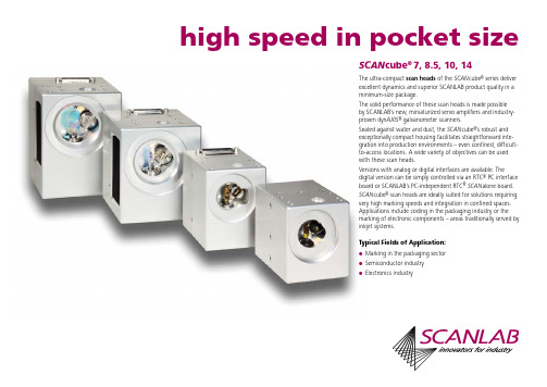
The ultra-compact scan heads of the SCAN cube® series deliver excellent dynamics and superior SCANLAB product quality in a minimum-size package. The solid performance of these scan heads is made possible by SCANLAB’s new, miniaturized servo amplifiers and industry® proven dynAXIS galvanometer scanners. Sealed against water and dust, the SCAN cube®’s robust and exceptionally compact housing facilitates straightforward integration into production environments – even confined, difficultto-access locations. A wide variety of objectives can be used with these scan heads. Versions with analog or digital interfaces are available. The digital version can be simply controlled via an RTC® PC interface board or SCANLAB’s PC-independent RTC® SCAN alone board. SCAN cube® scan heads are ideally suited for solutions requiring very high marking speeds and integration in confined spaces. Applications include coding in the packaging industry or the marking of electronic components – areas traditionally served by inkjet systems. Typical Fields of Application:
莱驰大容积振动盘式研磨仪NEW RS 300 XL说明书

粉碎设备 | 辅助设备 | 测试设备适合大体积样品N E WR S300X L大容积振动盘式研磨仪zz2研磨的艺术成立于1915年的德国RETSCH(莱驰)公司是Verder Group(弗尔德集团)里Scientific Division(科学仪器事业部门)的核心品牌之一,是全球最大的实验室固体样品前处理暨研磨粉碎筛分设备的生产厂家,在商检、质检、高校、农业、生物、制药、化工、研究所等领域有广泛的客户基础。
测量微米级粉体的粒度粒形分析仪w ww.re t sc h-t e ch n ol o g y.c n固体样品的研磨、粉碎、筛分及粒度分析w ww.re t sc h.c nw ww.el t r a.c o m/c n碳、硫、氧、氮、氢元素分析仪w ww.ca r bo l i te-ge r o.c n实验室及工业用马弗炉、烘箱、真空气氛炉金相学仪器w ww.at m-m.co m关于我们3莱驰-百年不断的创新样品前处理设备全球市场领导者——德国制造弗尔德(上海)仪器设备有限公司(Verder Shanghai Instruments and Equipment Co., Ltd.)其前身是弗尔德莱驰(上海)贸易有限公司(Verder Retsch Shanghai Trading Co., Ltd.)是弗尔德集团(Verder Group)在华设立的全资分公司,总部在上海,在北京、广州等地设有办事处。
公司业务主要分成Liquids Division(流体事业部门)和Scientific Division(科学仪器事业部门)。
成立于1915年的德国RETSCH(莱驰)公司是Scientific Division(科学仪器事业部门)的核心品牌之一,是全球最大的实验室固体样品前处理暨研磨粉碎筛分设备的生产厂家,主要产品为超离心研磨仪ZM200、颚式破碎仪BB系列、盘式研磨仪DM200/RS300XL、行星球磨仪PM系列、刀式捣磨仪GM200/GM300,冷冻研磨仪MM400/Cryomill,筛分仪AS系列,快速干燥仪TG200、自动分样仪PT100/PT200/PT600XL,压片机PP25/PP40等,在商检、质检、高校、农业、生物、制药、化工、研究所等领域有广泛的客户基础。
SICK nanoScan3 I O 安全区域雷射掃描器操作说明书
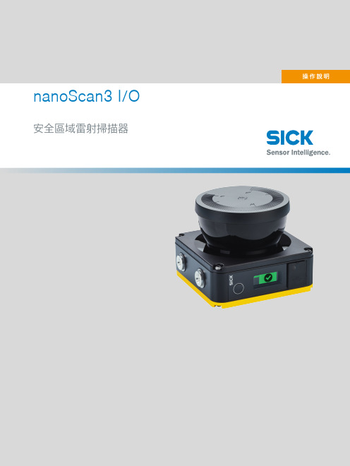
nanoScan3 I/O 安全區域雷射掃描器所述產品nanoScan3 I/O製造商SICK AGErwin-Sick-Str. 179183 Waldkirch德國法律聲明本文件受版權保護。
其中涉及的一切權利歸 SICK AG 公司所有。
僅允許在版權法的範圍內複製本文件的全部或部分內容。
未經 SICK AG 公司的明確書面許可,禁止對該文件進行修改、刪節或翻譯。
文件所提及的商標為其各自擁有者所有。
© SICK AG.版权所有。
原始文件本文件是 SICK AG 原始文件。
2操作說明 | nanoScan3 I/O8024611/1LJ8/2023-08-14 | SICK如有更改,恕不另行通知目錄目錄1關於本文件 (8)1.1適用範圍 (8)1.2本操作說明的目標群體 (8)1.3更多資訊 (8)1.4符號和文件使用慣例 (8)2關於安全資訊 (10)2.1基本安全提示 (10)2.2按規定使用 (11)2.3違規使用 (11)2.4網路安全 (11)2.5合格人員的要求 (11)3產品說明 (13)3.1透過SICK Product ID識別產品 (13)3.2裝置概覽 (13)3.3結構與功能 (14)3.4產品特性 (15)3.4.1產品系列 (15)3.4.2系統插頭 (16)3.4.3區域類型 (16)3.5應用示例 (16)4專案規劃 (19)4.1機器製造商 (19)4.2機器運營商 (19)4.3設計 (19)4.3.1免受影響 (20)4.3.2避免不受保護的區域 (20)4.3.3參考輪廓監控 (21)4.3.4監控情況切換的時間點 (23)4.3.5固定應用中的最小距離 (24)4.3.6適用於由反射決定的量測誤差的附加距離Z R (24)4.3.7危險區域防護 (25)4.3.8危險點防護 (28)4.3.9通道防護 (30)4.3.10可移動的危險區域防護 (31)4.4整合至電氣控制器中 (35)4.4.1電磁相容性 (36)4.4.2電源電壓供給裝置 (36)4.4.3USB接頭 (36)4.4.4OSSD (37)4.4.5控制輸入 (38)4.4.6通用輸入、通用輸出、通用I/O (40)8024611/1LJ8/2023-08-14 | SICK操作說明 | nanoScan3 I/O3如有更改,恕不另行通知目錄4.4.7重啟鎖定 (40)4.4.8外部設備監控(EDM) (42)4.5接入網路中 (43)4.5.1網路服務與埠 (43)4.6檢查方案 (43)4.6.1規劃調試時和特殊情況下的檢查 (43)4.6.2規劃定期檢查 (44)4.6.3關於檢查的說明 (45)5裝配 (47)5.1安全 (47)5.2拆封 (47)5.3安裝系統插頭 (47)5.4安裝裝置 (48)6電氣安裝 (49)6.1安全 (49)6.2連接 (49)6.2.1附M12 8Pin插頭的電纜線 (49)6.2.2附M12 17Pin插頭的電纜線 (50)6.2.3附開放式電纜端的17線電纜線 (52)6.2.4網路接頭 (53)7配置 (54)7.1交付狀態 (54)7.2設定軟體Safety Designer (54)7.2.1安裝Safety Designer (54)7.2.2專案 (54)7.2.3使用者介面 (55)7.2.4使用者群組 (55)7.2.5設定 (56)7.2.6配置 (57)7.3概覽 (59)7.4網路設定 (60)7.4.1Ethernet (60)7.5Time synchronization(時間同步) (60)7.6讀取配置 (61)7.7識別 (61)7.8應用 (62)7.9監控平面 (62)7.10參考輪廓區域 (64)7.11區域 (65)7.11.1建立區域組範本 (67)7.11.2匯入與匯出區域組和區域 (68)7.11.3Background image(背景圖像) (68)7.11.4區域編輯器的設定 (69)4操作說明 | nanoScan3 I/O8024611/1LJ8/2023-08-14 | SICK如有更改,恕不另行通知目錄7.11.5藉助座標編輯區域 (69)7.11.6繪入不可監控區域 (71)7.11.7確定全域幾何結構 (71)7.11.8推薦區域 (72)7.12輸入輸出,本地 (73)7.12.1Outputs(輸出) (74)7.12.2Inputs(輸入) (74)7.12.3一些信號的其他設定 (75)7.13監測情況 (76)7.13.1針對監控情況表的設定 (76)7.13.2多個監控情況表 (78)7.13.3監控情況設定 (78)7.13.4Input condition(輸入條件) (78)7.13.5關斷路徑 (78)7.13.6分配區域組 (79)7.13.7分配確定的關斷行為 (79)7.14模擬 (80)7.15資料輸出 (81)7.16傳輸配置 (82)7.16.1驗證配置 (82)7.17啟動和停止安全功能 (83)7.18報告 (84)7.19服務 (84)7.19.1Device restart(裝置重啟) (84)7.19.2出廠設定 (85)7.19.3管理密碼 (85)7.19.4Access management(存取管理) (86)7.19.5鏡頭蓋校準 (87)7.19.6比對設定 (87)8初始試運行 (89)8.1安全 (89)8.2概覽 (89)8.3校準 (89)8.4接通 (89)8.5調試和更改期間的檢查 (90)9操作 (91)9.1安全 (91)9.2定期檢查 (91)9.3顯示元件 (91)9.4藉著顯示器的狀態顯示 (92)10維護 (95)10.1安全 (95)10.2定期清潔 (95)8024611/1LJ8/2023-08-14 | SICK操作說明 | nanoScan3 I/O5如有更改,恕不另行通知目錄10.3更換鏡頭蓋 (95)10.4更換安全區域雷射掃描器 (97)10.4.1更換不帶系統插頭的安全區域雷射掃描器 (98)10.4.2更換帶系統插頭的安全區域雷射掃描器 (98)10.5更換系統插頭 (99)10.6定期檢查 (99)11故障排除 (100)11.1安全 (100)11.2藉著顯示器的詳細診斷 (100)11.3顯示器上的故障顯示 (100)11.4藉著Safety Designer診斷 (103)11.4.1資料記錄器 (103)11.4.2事件歷程 (104)11.4.3訊息歷程記錄 (106)12停止運行 (107)12.1廢物處理 (107)13技術規格 (108)13.1版本號和功能範圍 (108)13.2技術資料 (108)13.3反應時間 (113)13.4OSSD測試的時間進程 (113)13.5掃描範圍 (114)13.6尺寸圖 (117)14訂購資訊 (118)14.1供貨範圍 (118)14.2訂購資料 (118)15備件 (119)15.1更多備件 (119)16附件 (120)16.1系統插頭 (120)16.2其他配件 (120)17術語表 (121)18附錄 (123)18.1符合性與證書 (123)18.1.1欧盟合规性声明 (123)18.1.2英国合规性声明 (123)18.2關於標準的提示 (123)18.3許可證 (125)18.4起始試運行和試運行檢查清單 (126)6操作說明 | nanoScan3 I/O8024611/1LJ8/2023-08-14 | SICK如有更改,恕不另行通知目錄19圖片目錄 (127)20表格目錄 (129)8024611/1LJ8/2023-08-14 | SICK操作說明 | nanoScan3 I/O7如有更改,恕不另行通知1 關於本文件1關於本文件1.1適用範圍產品本文件適用於下列產品:•產品名稱:nanoScan3 I/O•銘牌條目「Operating Instructions」:8024594文件識別號文件訂貨代號:•本文件:8024611•本文件的可用語言版本:8024594所有文件的最新版請參閲:。
振镜延时的调节和现象
振镜延时的原理与调节一共有5种延时分别为开光延时,关光延时, 跳转延时, 扫描延时,曲线延时下面分别介绍1.Laser On Delay (开光延时)下面称LOnDa.LOnD的作用原理和发生时间LOnD 发生在开光时当振镜到达指定位置后开始Mark运动,但并不同时出光而是延时LOnD后出光示意图图1 开光延时这个值可以设为负值当设置为负值表示当振镜到达指定位置后先出光LOnD后再开始Mark运动b. 设置值的单位这个值在Scanlab和Raylase单位都为微妙(us)但是在Raylase中此值的绝对值不能低于50,在Scanlab 无此限制c.设置过大或者过小时的情形设置LOnD 过小时可以看到开光处产生了爆点(产生此情形的原因是由于振镜开始运动速度低而LOnD又过小这时候出光导致激光在开始处聚集导致爆点)图2 开光延时太小设置LOnD 过大时可以看到开光处有一部分少刻了(产生此情形的原因是由于振镜开始运动而LOnD过大过了很久再出光导致激光刻蚀时已经离开开始点很远导致有一部分少刻了)图3 开光延时太大LOnD设置一般和激光的开光状态相关一般如果激光开光状态能量较强则LOnD设置也需要相应的增大一些2.Laser Off Delay (关光延时)下面称LOffDa.LOffD的作用原理和发生时间LOffD 发生在关光时当振镜刻蚀到达指定位置后要结束Mark运动,但并不同时关光而是延时LOffD后关光示意图图4 关光延时这个值可以设为负值当设置为负值表示当振镜还未到达指定位置前LOffD的时候已经将光关闭即提前关光b. 设置值的单位这个值在Scanlab和Raylase单位都为微妙(us)但是在Raylase中此值的绝对值不能低于50,在Scanlab 无此限制c.设置过大或者过小时的情形设置LOffD 过小时可以看到关光处少刻了一段(产生此情形的原因是由于振镜结束运动时由于指令和运动有时间差, 即指令认为已经到位但实际还未到到位, 而LOffD又过小这时候关光导致激光在结束处少刻一段)图5 关光延时太小设置LOffD 过大时可以看到关光处产生爆点(产生此情形的原因是由于振镜结束运动时,振镜已经到位, 而LOffD又过大这时候还未关光导致激光在结束处产生爆点)图6 关光延时太大LOffD的设置一般和扫描速度相关一般扫描速度越大则LOffD也需要越大3.Jump Delay (跳转延时,快跳延时)下面称JumpDa.JumpD的作用原理和发生时间JumpD 发生在振镜跳转后当振镜跳转到指定位置后延时JumpD的时间再开始别的运动示意图图7 跳转延时这个值不可以设为负值b. 设置值的单位这个值在Scanlab中单位为10微妙(10us)即设置1 代表10us 最小可设0 在Raylase中单位为微妙(us)即设置1 代表1us 但是最小值是50c. 设置过大或者过小时的情形设置JumpD 过小时可以看到在Jump后的下一段运动开头时有不稳定的现象产生(产生此情形的原因是由于振镜结束Jump运动时,振镜电机还未稳定, 而JumpD又过小这时候下一段运动时振镜还在不稳定状态导致此现象发生)图8 跳转延时太小设置JumpD 过大时不会有不稳定的现象产生但是会影响效率JumpD的设置一般和振镜快跳速度相关一般的如果振镜跳转速度越大则JumpD也需要越大4.Mark Delay (扫描延时)下面称MarkDa.MarkD的作用原理和发生时间MarkD 发生的条件是: 在Mark指令后下一条是Jump指令它在Mark指令后会产生MarkD, 即振镜刻蚀到指定位置后延时MarkD的时间再开始跳转指令连续的Mark指令之间不会产生MarkD示意图图9 扫描延时这个值不可以设为负值b. 设置值的单位这个值在Scanlab中单位为10微妙(10us)即设置1 代表10us 最小可设0 在Raylase中单位为微妙(us)即设置1 代表1us 但是最小值是50c. 设置过大或者过小时的情形设置MarkD 太小时可以看到还没到刻蚀的终点位置就直接开始下一段Jump运动了导致关光处出现拐角(产生此情形的原因是由于振镜理论位置和实际位置存在时间差, 理论上运动已经到位但实际还未到位, 而MarkD又过小这时候下一段Jump 运动已经开始导致此现象发生)图10 扫描延时太小设置MarkD 过大时不会有不稳定的现象产生但是会影响效率MarkD的设置一般和振镜扫描速度相关一般的如果振镜扫描速度越大则MarkD也需要越大5. Poly Delay (拐角延时, 转角延时,曲线延时)下面称PolyDa.PolyD的作用原理和发生时间PolyD 发生连续Mark指令之间即上一条Mark运动执行完毕后等待PolyD的时间再执行下一个Mark运动, 期间激光不会关闭示意图图11 曲线延时这个值不可以设为负值b. 设置值的单位这个值在Scanlab中单位为10微妙(10us)即设置1 代表10us 最小可设0在Raylase中单位为微妙(us)即设置1 代表1us 可设0 ,但是设置比0大的值必须从50开始c. 设置过大或者过小时的情形设置PolyD 过小时可以看到在两段连续的Mark运动之间拐角处有圆弧过渡导致和实际需求图形不符(产生此情形的原因是由于前一段Mark结束振镜电机还未到位, 而MarkD又过小这时候下一段Mark时振镜只能从走捷径路径导致此现象发生)图12 PolyD太小设置PolyD 过大时可以看到在两段连续的Mark运动之间拐角处有爆点(产生此情形的原因是由于前一段Mark结束振镜电机已经到位, 而PolyD又过大, 这时候下一段Mark还未开始但是激光仍然在出导致爆点产生)图12 PolyD太大PolyD的设置一般和振镜扫描速度和拐角大小相关一般的如果振镜扫描速度越大拐角越大则PolyD也需要越大综合上述分析和原理我们可以得出如下延时设置必须遵循的规则1. LOffD > LOnD (关光延时必须大于开光延时,否则在刻蚀短线段时会产生问题)2.MarkD > LOffD –LOnD (扫描延时必须大于关光延时和开光延时的差,否则在进行短距离跳转时再刻蚀时会出现问题)延时的设置要根据激光的特性(频率,能量,首脉冲等),扫描速度和快跳的速度,再结合上述延时设置不当时出现的典型情形,综合考虑力求达到既能满足刻蚀图形不变形, 效率又高的最佳状态.3.。
德盟电子硬式检查镜使用手冊说明书

使用手冊 UM-006
1
1
3 2
握把隔離器
鏡頭
USB接頭
Adronic User Manual
4.錄影請按右側錄影按鍵
6.點進右上角設定鍵,可自行設定相片/影片品質
若想擁有更完善的功能體驗,可向德盟購置相關軟體7.關機:將USB接頭拔除即可自動關機
09.儲存與回收方式
使用時,切勿將鏡頭插入患者耳內太深,以避免患者受傷
a) b) c ) d) 注意!本產品若要長時間停用時,應保存在溫度為-20 ℃~50 ℃,相對濕度≤95%(無水氣凝結),無腐蝕性氣體及通風良好的環境下。
儲存及運送環境超出上述指定範圍之外,可能會影響本產品性能。
注意!請勿保存及放置在較多震動、塵埃或具有腐蝕性氣體的場所。
將本產品保存在以上環境時,可能會影響本產品功能及性能。
注意!本產品若經過保存在低於 0 ℃環境時,必須至少要在常溫環境下靜置24小時以上才能正常操作。
注意!在運送過程中,應考慮機械衝擊、劇烈振動和受潮等問題,做好適當的防護。
本儀器請於室溫及乾燥的環境下儲存。
長期不使用時,請拔除電源。
環境條件:-20 °C ~ 50 °C或 -4 °F ~ 122 °F,相對溼度 ≦ 95% (無水氣凝結),無腐蝕性氣體及通風良好的環境。
防水(鏡頭有防水)功能,使用時應避免液體淋溼,造成儀器損壞。
模特克BA400模块化显微镜平台产品说明书
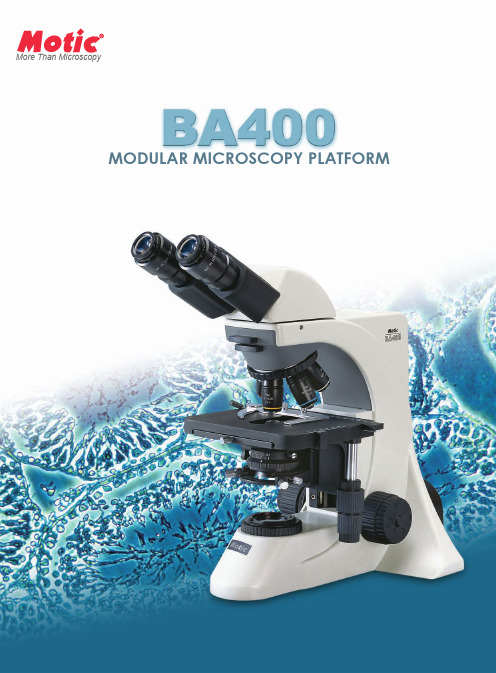
More Than MicroscopyMODULAR MICROSCOPY PLATFORM01The Microscope StandBA400(Trinocular)BA400New legal requirements and renewed emphasis on the ergonomics of the microscope have catapulted the importance of the stand to the forefront.The BA400's overall design was conceived from the user's point of view for a necessary layout suited for continuous and expandable usage.The wide arm design providesstrength and rigidity forconstant usage.Additionally,the inverted"Y"support in theback of the microscope assiststhe extra lateral stability of theBA400.Furthermore,theBA400's1:1.6body distributionratio is ideal for those workstations constrained by theever-increasing premium onspace.Engineered to feel like a personalmicroscope,the BA400's ergonomiclayout is compatible with themanner in which you work.Lowposition focus controls and stagemovement mechanisms and thelocation of the illumination intensitycontrols were designed to minimisefatigue.The ideal location guaranteesmanipulation is stress free andeffortless.02Eyepiece DescriptionF.N.Diopter AdjustmentReticule Widefield Plan High Eye Point 10x 225oAccepts24mmWidefield Plan 12.5x 16--Widefield Plan 15x14.5--Widefield Plan High Point 10x w/Plain Cross Hair225o Plain Cross HairMore Than Microscopy Graduated cross hair point =0.1mm/10mmGraduated linear line point =0.1mm/10mmPlain cross hairConstructed at the comfortable angle of 30o and incorporating the Siedentopf interpupilliary adjustment system [55-75mm],the BA400's observation tubes guarantee hours of fatigue free usage withfield flatness up to F.N.22.Opting for the trinocular tube expands the platform functionality of the BA400to include documentation.The ball bearing mechanism of the BA400's nosepiece with the internal clickstopsystem ensures parcentration with everymagnification turn.Reversed for rapid specimen changeswithoutobjectivecontamination,the nosepiece assimilates up to five separateobjectives.Integratingthe Motic CCIS system with field flatness up to F.N.22and the high eye point principle,the BA400's eyepieces transfer true colour and sharp images to minimise fatigue and eye strain.Various other magnifications are available for application specific tasks.A selection of reticules are also available.EyepiecesReticulesFor those environments where user and bench height are completely opposite,a series of eyepiece risers may be incorporated for additional 20mm of height [up to 3can be integrated for a total height adjustment of 60mm].400Posture ManagementNosepiece03Mechanical StageHard coated for longevity through the prevention of abrasionandwear,themechanical stage offers a working surface of 174 x 145mm with cross movement, via ball bearing mechanism, of 76 x 50mm. Adjustable torque adjustment is available for both X and Y axes controls toprovide the tension you are comfortable with. Available as either a left or right-handed control coaxial mechanical stage, the BA400's stage has a vernier scale readability of 0.1mm and a Z-axis focus stop to prevent unnecessary damage. The stage is also rotary for photomicrography composition.CondenserSwing-put Achromat N.A. 0.9/0.13The dovetail-mounted swing out Achromat condenser with a N.A. 0.90 showcases homogeneousilluminationfor observation andphotomicrography for magnifications 2x to 100x. Condenser height is adjustable through the rack and pinion mechanism and the overall condenser is easily centrable with a pair of adjustment screws.04CCIS Plan Achromat Phase Turret CondenserPhase CenteringTelescopeOptionally available with three-filter block [excluding dummy cassette] slider axis for reflected light fluorescence, the BA400 transforms into a fluorescence microscopy platform covering routine FITC to GFP markers. The BA400's fluorescence versatility allows for one microscope to be used for simply fluorescence screening diagnosis to research analysis, saving both space and budget expenses.Simple PolarisationDesigned for simple polarisation, the BA400 is equipped standard with filter slots in its upper stand. RetardationPlate360o Rotary Analyser Polariser(below condenser)Polariser (above collector)Fluorescence Microscopy*High contrast imaging via phase employment is offered in two formats with the BA400. Combining the N.A 1.25 Phase Contrast Turret Condenser with Motic's CCIS Plan Phase objectives offers For applications requiring both phase and dark field contrast, BA400's Phase Dark field Turret Condenser is the ideal solution. Incorporating three phase positions [10x, 40x, and 100x] with a dark field position [for 10x - 40x observation] and an iris diaphragm, the condenser switches rapidly between techniques.* Please check with your local Motic supplier for availabiltiy.More Than Microscopy05MVH-5 Five-Head ConfigurationMVH-2S Two-Head Observationextraordinary.06With a uniform and intense 30W external Koehler illumination source, the BA400 ensures effective illumination for accurate and proper diagnosis of pathological specimens. Furthermore, modularity of the BA400 represents a multi function microscopy platform for the condensed space associated with today's laboratories.Expanding the function of fluorescence excitation beyond simple observation, the BA400 EPI's adaptation of the Moticam 3000C and fluorescence software offers a platform for documentation, observation, file-sharing, and diagnosis in one ideal station. Better image management, better work efficiency, and better space utilisation are the hallmarks of this platform.RetardationPlate360o Rotary AnalyserPolariser(below condenser)Polariser(above collector)Documentation and Analysis StationTissue Culture and Blood Smear ScreeningFluorescence Analysis PlatformPathology PlatformMore Than Microscopy07Utilising the trinocular head format of the BA400,the addition of the 2.5X SLR Projection lens plus your choice of the 2.5x and 4x photo eyepiece.The desired image clarity and quality is easily captured.DocumentationDocumentation,a standard requirement for all applications in today's society,is available for the BA400in three options:one photomicrography andtwo versions ofdigital photomicrography.Adapter Chip Sensor Size 0.5x 1/2"chip sensor 0.65x 2/3"chip sensor 1.0x1/3"-2/3"chip sensorSchematic DiagramsUnit:mmBA400(Trinocular)Convenient to mount,the DMBA400digital 3-megapixel camera head digitalises your observation for sharing amongst colleagues,analysis,and documentation.Streaming live images,via the USB2.0cable,at 2048x 1536and with integratedreal -time filtering and noise reduction,the DMBA400head and standard software,Motic Images Plus,optimises the BA400into a training,teaching,and analysis station without the extra space associated with these activities.Another option for digitalisation is the selection of Motic's line of digital cameras to deliver crisp images even from weak fluorescence images.The Moticam 3000C utilises a Peltier cooling system with image transfer via FireWire to transform the BA400into a fluorescence analysis platform when combined with a fluorescence software.Digitalisation of microscopy is Motic's philosophy and to the right is the available camera adapters for the BA400to assist your digitalisation.372202457068410188292240781812.5X SLR Projection lens -requires combination with one of the below photo eyepieces*Final adapter must be provided by camera manufacturer2.5X Photo Eyepiece 4.0X PhotoEyepiece2E Digital Documentation08DMBA400Standard SpecificationsSchematic Diagrams2401817870470202457068410372292DM -BA400-BUnit:mmMore Than MicroscopyCode:SP010685F 09.2007Certified ISO 9001Certified ISO 14001Motic Incorporation Ltd.(HONG KONG)Rm.2907-8,Windsor House,311Gloucester Road,Causeway Bay,Hong Kong Tel:852-********Motic Instruments Inc.(CANADA)180-4320Viking Way Richmond,B.C.V6V 2L4Canada Tel:(604)303-9033Fax:(604)303-9043Toll Free:1-877-977-4717Technical Support:1-877-901-4141Email:info@motic For inquiries in UK (UK)Saracens House,25St.Margarets Green,Ipswich,IP42BN,Suffolk,UK Tel:44-(0)-1473281909Motic Deutschland GmbH (GERMANY)Gewerbepark Spilburg,Gebaude A42Spilburgstrasse 1D -35578Wetzlar Germany Tel:49-6441-210010Motic Spain,S.L.(SPAIN)Pol ígon Industrial Les Corts,Cam ídel Mig,11208349Cabrera de Mar,Barcelona Spain Tel:34-93-7566286Fax 34-93-7566287MicroscopesDesign Change:The manufacturer reserves the right to make changes in instrument design in accordance with scientific and mechanical progress,without notice and without obligation.Motic Incorporation Ltd.Copyright2002-2003,2007.All Rights Reserved。
scanlab牌rtc5型原理_解释说明以及概述

scanlab牌rtc5型原理解释说明以及概述1. 引言1.1 概述本文将详细探讨并解释Scanlab牌RTC5型的原理,以及对其进行概述。
RTC5型是一种先进的扫描系统,广泛应用于工业生产、科学研究和艺术创作等领域。
通过深入了解RTC5型的原理和功能特点,我们可以更好地理解它在不同领域中的应用和优缺点。
1.2 文章结构本文将按照以下结构展开:首先,在2节中我们将进行RTC5型的原理解释说明。
然后,在3节中,我们将探讨RTC5型在不同领域的具体应用。
接着,在4节中我们会对RTC5型的优缺点进行分析评估。
最后,在第5节中,我们会给出文章总结回顾,并对RTC5型展望和建议。
1.3 目的本文旨在提供一个全面而清晰的介绍关于Scanlab牌RTC5型的内容以及其原理。
通过阅读本文,读者将能够了解到RTC5型在工业、科研和艺术领域应用时所涉及到的核心知识,并对其使用和未来发展有更加深入的认识。
此外,本文还致力于帮助读者了解RTC5型的优劣势,以促进技术的进一步提升和创新。
2. RTC5型原理解释说明2.1 RTC5型概述Scanlab牌RTC5型是一种高性能的激光扫描控制器,被广泛应用于工业、科学研究和艺术创作等领域。
它采用先进的数字信号处理技术,能够精确地控制和驱动激光扫描系统,实现高速而稳定的激光扫描操作。
RTC5型具有多通道输出、高分辨率和快速反馈等特点,使其成为当今最受欢迎的激光扫描控制器之一。
2.2 原理解释RTC5型的原理是基于光电传感器和数字信号处理技术。
它主要由三个关键部分组成:输入/输出接口、数模转换器和数字信号处理器。
输入/输出接口是与外部设备连接的接口,通过支持多通道输入/输出模块,能够灵活地与其他设备进行数据交互。
这样就可以实现与激光源、功率调节器以及其他外围设备的无缝对接,从而提供了更大的灵活性和可扩展性。
数模转换器(DAC)是将数字信号转换为模拟电压或电流输出的设备。
RTC5型采用高精度DAC,将数字数据转换为控制激光扫描系统的模拟信号。
- 1、下载文档前请自行甄别文档内容的完整性,平台不提供额外的编辑、内容补充、找答案等附加服务。
- 2、"仅部分预览"的文档,不可在线预览部分如存在完整性等问题,可反馈申请退款(可完整预览的文档不适用该条件!)。
- 3、如文档侵犯您的权益,请联系客服反馈,我们会尽快为您处理(人工客服工作时间:9:00-18:30)。
1000 1500 3000 5000 5000
Cutting Drilling Scribing, deep-engraving Soldering Trimming Texturing Structuring Perforating Heat treatment Processing of curved surfaces
Micro-machining
Rapid Manufacturing
Stereolithography Laser sintering Rapid tooling Laser engraving
The modular design of powerSCAN 50 and 70 allows easy exchange of individual components.
These focusing devices dynamically vary the focal length and thereby extend XY scan heads into versatile 3D beam deflection systems. The varioSCANFLEX enables a continuous variation of the image field size.
SeongKyeong Photonics
6
info@
Working distance
Focal Diameter The focal diameter of the laser spot depends on the laser wavelength, the scan system’s aperture and the focal length of the system’s focusing optics, as well as the quality of the coupled laser beam.
SCANLAB enables
Single-Axis Modules XY Scan Modules SCANcube ® SCANgine ® hurrySCAN ® hurrySCAN ® II
SCANLAB‘s industry-proven galvanometer scanners and servo amplifiers are the core components for reliable laser positioning systems. This combination of two single-axis modules enables the deflection of laser beams in two dimensions. Scan heads of this series integrate all scan components in a sealed ultra-compact housing. Featuring a uniform housing format, these compatible scan heads enable a broad range of applications. They deliver excellent dynamics and superior product quality. Scan heads of this series are equipped with an innovative fully digital servo electronics. Advanced status signals create new control and remote-diagnosis possibilities.
Laser Materials Processing
SCAN cube ®
SCANgine ®
hurrySCAN ® hurrySCAN ® II
7 100 50 1100 800 10 150 100 800 500 14 250 200 350 220
intelliSCAN ®
hurrySCAN ®
max. 8 200 200 max. 16 4000 / 4000 / 4000 750 / 1000 / 1500 max. 16 4000 2000 max. 16 4000 / 2000 / 2000 -
7 100 50 1000 780
10 150 100 640 400
SeongKyeong Photonics
3
info@
Power
Remote Welding
Cutting
Perforation Heat Treatment Engraving Rapid Manufacturing
Soldering
Drilling Micro-Machining
hurrySCAN ® 20 / 25 / 30 powerSCAN varioSCAN Optical Components
Maximum dynamic performance and high laser power capability are delivered by these compatible scan heads. Their innovative design also includes air and water cooling.
powerSCAN
Scan Head hurrySCAN ® 20 / 25 / 30 powerSCAN 33 powerSCAN 50 / 70 with with with with varioSCAN 20 varioSCAN 40 varioSCAN 60 / 80 varioSCAN 40
Medical Systems
Hale Waihona Puke
Biomedical systems Ophthalmology
Science and Research
(1)
characters per second with single-stroke characters of 1 mm height, f = 160 mm F-Theta objective (f = 163 mm F-Theta objective for hurrySCAN 20 / 25 / 30)
Scan systems of this product line enable new applications in the multikW laser power range. Large working fields and volumes are achievable together with small spot diameters.
Objective
2 Digital interface 3 Digital or analog servo amplifier boards
Scan volume
SeongKyeong Photonics
5
info@
y
· f · M² · k d
= s
Image field size
SCANLAB scan systems can be supplied with a wide range of objectives and mirrors. Customer-specific designs are available.
20, 25, 30
33, 50, 70
8 / 20, 16 / 40, 16 / 60, 16 / 80
intelliSCAN ®
Apertures in mm
7, 10, 14, 20, 25, 30, 33, 50, 70
7, 10, 14, 20, 25, 30
7, 10
7, 10, 14
10
SeongKyeong Photonics
1
info@
positioning and focusing laser beams
10 150 100 300 200
14 250 200 220 140
10 150 100 800 500
20 750 320 210
25
30
33
50 -
70 -
Nd:YAG@1064 nm CO2 good quality high quality
4000 4000 4000 5000 260 170 220 150
06 / 2005 Information is subject to change without notice.
Processing-on-the-fly Inspection, identification Large field scanning Precision display systems Material sorting Product individualizing
SeongKyeong Photonics
2
info@
for a wide range of applications.
Application Matrix
Entrance aperture [mm] Max. laser power [W] Writing speed [cps] (1) Marking Welding Coding Remote welding
