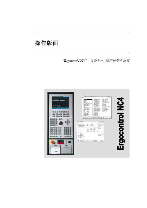
德国kado纠偏操作手册簿
大车纠偏卡手册

纠偏卡
副
端
端
梁
梁
变
变
频
频
器
器
自由轮 1
主 端 梁
电机 A 编码器 1
电机 C 编码器 2
电机 B
图 1 双变频系统结构图
电机 D
自由轮 2
副 端 梁
2.1.1 参见图 1,起重机大车由两台变频器分别驱动大车两侧的电机(电机 AB 和 CD),其中一台变频器 配有纠偏卡,这台变频器称为主变频器,其驱动的电机称为主端梁电机。
SpeedSet1 SpeedSet2 SpeedSet3 SpeedSet4 E2 E3 E4 E5
OTT Auto_Lim Alarm_Lim Manual_Lim Percent1 Percent2 E6 Use_EncoderCard
例如大车速度 120 米/分,使用的编码器的每转脉冲数为 1024,需要的分辨率为 1 毫米,则自由轮的直径 为:
120*1024/300/3.14≈130mm ≤ 自由轮直径 ≤ 1×1024/3.14≈326mm
自由轮尺寸过小无法满足系统对输入频率的限制,过大会降低系统分辨率。 选择编码器时其电压等级应能承受 24VDC,编码器安装和接线时要注意方向,保证在大车正向运行时编码器 执行加计数,(起重机运行方向参考图 8)。
Hz
S8 不作处理偏差
毫米
S9 自动纠偏偏差
毫米
S10 报警纠偏偏差
毫米
S11 自动纠偏停止
毫米
S12 超偏差停车类型 S13 自动纠偏限速 S14 报警纠偏限速 S15 偏差超限故障限速 S16 自动纠偏修正比例 S17 报警纠偏修正比例 S18 系统偏差纠正 S19 使用编码器卡
德马格中文操作说明书
液压顶出 后退 / 前进
气阀 1-4 打开
中子 抽芯 / 进芯
自动安全门 打开 / 关闭
Rotary table index bolt move in / move out
模厚调整 增加 / 减小
旋转模板 逆时针 /顺时针
提示 “模厚调整”按钮只针对曲轴式机床。“自动安全门”和“气阀 1-4”按钮只有当这些功 能配置以后才起作用。“Rotary table latches”, Rotary table index bolt” and “旋转模板”应 用于带转转模板的多色注塑 。
Sfu服EnRc务tVio页InC面Egr功oup 能组
Afu报LnAc警tRio功Mn能Sgr组oup
Fig. 2: 功能选择键
1.2 手动功能键
在手动和点动模式下可通过下面的按钮(见Fig. 3 和 Fig. 4)进行相应的操作。 Fig. 3: 手动模具装置功能
模具 打开 / 闭合
Rotary table latches move in / move out
4.4
帮助功能键和专家系统 .......................................................................................................19
5
频幕 ..........................................................................................................20
Pfu程RnOc序tGio功Rn能AgrM组oSup
Process 过Pfu程RnOc控tCio制EnS功gSr能oCu组pONTROL
Cascade E和F系列叉头位器操作指南说明书

cascade®corporationCascade is a Registered Trademark of Cascade Corporatione & F-seriesManual Number 688261-r3Fork positionerIntroduction i Safety Rules 1 Daily Inspection 3 Fork Positioner Operation 4 Safe Operation and Maintenance 5 OHSA Regulations 5i This guide describes operating instructions for the Cascade E and F-Series Fork Positioners. It will help you avoid common errors which often cause damage to the equipment or product being handled.Read this manual thoroughly before operating the attachment. Be sure you know and understand all operating procedures and safety precautions. If you have any questions, or don’t understand a procedure, ask your supervisor.Emphasize Safety! Most accidents are caused by operator carelessness or misjudgement. You must watch for hazardous situations and correct them.F-SeriesSideshift CylinderValve1RAMPSNo loadWith load23Check items each day. Report problems to yoursupervisor. See service manual for maintenance and repair procedures.4GA0005.epsFORK POSITIONER WITH STaNDaRD ValVEA Sideshift LeftB Sideshift RightC Forks OutD Forks InFORK POSITIONER WITH SOlENOID ValVEA Sideshift LeftA Forks Out (press knob button)B Sideshift RightB Forks In (press knob button)Tilt forwardFP0016.epsA BAABBFP0016.epsABCCDD(a) General Requirement(4) Modifications and additions which affect capacity and safeoperation shall not be performed by the customer or userwithout manufacturers prior written approval. Capacity,operation and maintenance instruction plates, tags or decalsshall be changed accordingly.(5) If the truck is equipped with front-end attachments otherthan factory installed attachments, the user shall requestthat the truck be marked to identify the attachments andshow the appropriate weight of the truck and attachmentcombination at maximum elevation with load laterallycentered.(6) The user shall see that all nameplates and markings are inplace and maintained in a legible condition.(e) Safety Guards(2) If the type of load presents a hazard, the user shall equipfork trucks with a vertical load backrest extension inaccordance with (a)(2) following.(a)(2) All new powered industrial trucks acquired and usedby an employer after February 15, 1972 shall meet thedesign and construction requirements for powered industrialtrucks established in the “American National Standard forPowered Industrial Trucks, Part II, ANSI B56.1-1969”, exceptfor vehicles intended primarily for earth moving or over-the-road hauling.(l) Operator TrainingOnly trained and authorized operators shall be permitted tooperate a powered industrial truck. Methods shall be devised to train operators in the safe operation of powered industrial trucks. (m) Truck Operations(1) Trucks shall not be driven up to anyone standing in front of abench or other fixed object.(2) No person shall be allowed to stand or pass under theelevated portion of any truck, whether loaded or empty.(3) Unauthorized personnel shall not be permitted to ride onpowered industrial trucks. A safe place to ride shall beprovided where riding of trucks is authorized.(4) The employer shall prohibit arms or legs from being placedbetween the uprights of the mast or outside the running linesof the truck.(5i) When a powered industrial truck is left unattended, load engaging means shall be fully lowered, controls shall beneutralized, power shall be shut off and brakes set. Wheelsshall be blocked if the truck is parked on an incline.(5ii) A powered industrial truck is unattended when the operator is 25 feet or more away from the vehicle which remains in hisview, or whenever the operator leaves the vehicle and it isnot in his view.(5iii) When the operator of an industrial truck is dismounted and within 25 feet of the truck still in his view, the load engagingmeans shall be fully lowered, controls neutralized and thebrakes set to prevent movement.(6) A safe distance shall be maintained from the edge of rampsor platforms while on any elevated dock or platform orfreight car. Trucks shall not be used for opening or closingfreight doors.(10) A load backrest extension shall be used whenevernecessary to minimize the possibility of the load or part of itfrom falling rearward.(n) Traveling(4) The driver shall be required to slow down and sound thehorn at cross isles and other locations where vision isobstructed. If the load being carried obstructs forward view,the driver shall be required to travel with the load trailing.(7i) When ascending or descending grades in excess of10 percent, loaded trucks shall be driven with the loadupgrade.(7iii) On all grades the load and load engaging means shall be tilted back if applicable, and raised only as far asnecessary to clear the road surface.(o) Loading(1) Only stable or safely arranged loads shall be handled.Caution shall be exercised when handling off-center loadswhich cannot be centered.(2) Only loads within the rated capacity of the truck shall behandled.(3) The long or high (including multiple-tiered) loads whichmay affect capacity shall be adjusted.(4) Trucks equipped with attachments shall be operated aspartially loaded trucks when not handling a load.(5) A load engaging means shall be placed under the load asfar as possible; the mast shall be carefully tilted backwardto stabilize the load.(6) Extreme care shall be used when tilting the load forwardor backward, particularly when high tiering. Tilting forwardwith load engaging means elevated shall be prohibitedexcept to pick up a load. An elevated load shall not betilted forward except when the load is in a deposit positionover a rack or stack. When stacking or tiering, only enoughbackward tilt to stabilize the load shall be used.(p) Operation of the Truck(1) If at any time a powered industrial truck is found to be inneed of repair, defective, or in any way unsafe, the truckshall be taken out of service until it has been restored tosafe operating condition.(q) Maintenance of Industrial Trucks(1) Any power-operated industrial truck not in safe operatingcondition shall be removed from service. All repairs shall bemade by authorized personnel.(5) All parts of any such industrial truck requiring replacementshall be replaced only by parts equivalent as to safety withthose used in the original design.(6) Industrial trucks shall not be altered so that the relativepositions of the various parts are different from what theywere when originally received from the manufacturer, norshall they be altered either by the addition of extra parts notprovided by the manufacturer or by the elimination of anyparts. Additional counter-weighting of fork trucks shall notbe done unless approved by the truck manufacturer.(7) Industrial trucks shall be examined before being placed inservice and shall not be placed in service if the examinationshows any condition adversely affecting the safety of thevehicle. Such examinations shall be made at least daily.When industrial trucks are used on a round-the-clock basis,they shall be examined after each shift. Defects whenfound shall be immediately reported and corrected.5Do you have questions you need answered right now? Call your nearest Cascade Service Department.Visit us online at AMERICASCascade CorporationU.S. Headquarters2201 NE 201stFairview, OR 97024-9718 Tel: 800-CASCADE (227-2233) Fax: 888-329-8207Cascade Canada Inc.5570 Timberlea Blvd.Mississauga, OntarioCanada L4W-4M6Tel: 905-629-7777Fax: 905-629-7785Cascade do BrasilRua João Guerra, 134Macuco, Santos - SPBrasil 11015-130Tel: 55-13-2105-8800Fax: 55-13-2105-8899EUROPE-AFRICACascade Italia S.R.L. European Headquarters Via Dell’Artigianato 137050 Vago di Lavagno (VR) ItalyTel: 39-045-8989111Fax: 39-045-8989160Cascade (Africa) Pty. Ltd. PO Box 625, Isando 1600 60A Steel Road Sparton, Kempton Park South AfricaTel: 27-11-975-9240 Fax: 27-11-394-1147ASIA-PACIFICCascade Japan Ltd. 2-23, 2-Chome, Kukuchi Nishimachi Amagasaki, Hyogo Japan, 661-0978 Tel: 81-6-6420-9771 Fax: 81-6-6420-9777Cascade Korea121B 9L Namdong Ind.Complex, 691-8 Gojan-DongNamdong-KuInchon, KoreaTel: +82-32-821-2051Fax: +82-32-821-2055Cascade-XiamenNo. 668 Yangguang Rd.Xinyang Industrial ZoneHaicang, Xiamen CityFujian ProvinceP.R. China 361026Tel: 86-592-651-2500Fax: 86-592-651-2571Cascade India MaterialHandling Private LimitedNo 34, Global Trade Centre1/1 Rambaugh ColonyLal Bahadur Shastri Road,Navi Peth, Pune 411 030(Maharashtra) IndiaPhone: +91 020 2432 5490Fax: +91 020 2433 0881Cascade Australia Pty. Ltd. 1445 Ipswich Road Rocklea, QLD 4107 AustraliaTel: 1-800-227-223Fax: +61 7 3373-7333Cascade New Zealand15 Ra Ora DriveEast Tamaki, AucklandNew ZealandTel: +64-9-273-9136Fax: +64-9-273-9137Sunstream IndustriesPte. Ltd.18 Tuas South Street 5Singapore 637796Tel: +65-6795-7555Fax: +65-6863-1368© Cascade Corporation 2007 6-2007 Part Number 688261-R3 c。
DEK中文版操作手册

DEK中文版操作手册Dek篇1.设备操作手册1.1 机器认识11.2安全警告與小心为了确保印刷机操作状况在任何时间均保持安全,所有职员必须广泛地遵守并接受除在手册描述之特别安全注意事项外之安全规范.警告标示引起作业员与保养员对可造成死亡,重伤或病症的可能危险的注意.这些危险不是设备固有就是在设备操作时产生出来的.在机器上使用的警告卷标的范例展示于另一边的表格内.底下展示的结合警告和小心预防的卷标,贴于机台上意味着使用者尝试在设备上执行此作业前应先参阅技术参考手册内相关章节内容.小心标示警告职员随着偏离描述步骤所可能引发的人或料可能的损害.小心标示并不意味对职员的危险.一个小心标示的例子如下:小心摄影机损毁..不要留下任何未用治具于升降平台的后轨道后方区域.如有任何物体留在升降平台的PC板印刷区域外,当平台上升至印刷高度时,它将可能与摄影机相撞.警告: 惊叹号应用于未被特殊警示所涵盖的一切危险的一般警示.警告: 切割物在警示卷标附近存在锐利边缘伤害的危险.当在指定区域工作时需特别小心.警告: 刺激物存在会立即产生发炎的物质,并会重复或延长与黏膜或皮肤的接触.警告: 易燃物存在易燃物质,应远离热,燃烧源与静电放电,使用于通风良好区域.警告: 移动物在警示卷标附近存在移动对象,这些对象有能力造成伤害.设备外盖不可移开.警告: 辐射物在卷标附近存在因雷射光造成眼睛伤害的危险.不要直视光源或物体表面之直接反射光.警告: 受压物高压存在并可能造成伤害.不要企图直接开启系统至大气下.警告: 电力危险高电压存在并可能造成伤害或死亡.不要从设备外罩移除保护盖或不顾保护装置.警告定義21.3设备概观範圍這手冊應由適當訓練過的設備操作人員來使用.對於設備的一般操作狀況它是個快速入門指南.關於設備設定更深一層的資訊則總括到技術參考手冊項次說明1 觸控式螢幕2 系統按鈕3 滑鼠4 雙按鈕控制5 鍵盤6 主電源開關7 緊急開關按鈕8 錫膏滾動燈9 三色燈當機器啟動電源後,按下兩紅色緊急開關中任一能以受控方式使機器停止31.4人机接口狀態頁在主要控制螢幕上所顯示的資訊為狀態頁.狀態頁有兩種版本顯示模式.可在Set Prefs選單內Display Type螢幕顯示模式做選擇模式1模式2項次說明1 印刷機主題視窗2 製程參數視窗3 訊息提示帶4 項目單5 視覺資料視窗6 警告訊息視窗7 印刷機狀態視窗項次說明1 製程參數視窗2 設備參數視窗3 訊息提示帶4 項目單5 視覺資料視窗6 警告訊息視窗7 印刷機狀態視窗8 印刷機主題視窗在觸控式螢幕上觸壓相關的項目圖像便能完成功能選擇.另一種選擇方式是藉由鍵盤上功能鍵F1到F8來做選擇4視覺資料視窗可利用在狀態頁上的Zoom In或Zoom Out圖像來改變視覺資料視窗的大小.51.5三色灯此訊息燈顯示設備的作動狀態.設備無法作動系統電源關閉錯誤訊息顯示設備未在準備狀態設備在初始化燈號顏色作動狀態設備在設定中設備在維護下設備提示操作者注意卡匣錫膏不足擦拭紙卷用盡擦拭溶劑耗盡設備可作動設備在就緒狀態等待61.6 开机与登入1. 旋轉主電源開關至ON處.2. 設備提示時按壓System鈕.已選好的狀態頁模式會與下列功能選單一起顯示: 3. 觸壓Monitor (鍵盤上F7功能鍵).4. 觸壓Log On (F1).操作員登入視窗顯示:使用鍵盤輸入操作員I.D.後按下Enter鍵.5. 觸壓Exit (F8).71.7产品换线新產品1. 觸壓Setup (F6).2. 觸壓Load Data (F2).儲存於設備內所有產品檔案表會顯示出來:3. 使用Left, Right, Up和Down (F4, F5, F6和F7) 反白所需檔案.4. 觸壓Load (F1).選定的檔案會顯示在狀態頁.5. 觸壓Change Screen (F5).6. 系統提示時掀起前方印刷頭蓋.8912. 触压Change Tooling (F6).13. 触压Head (F2).14. 使用双控制钮抬起印刷头.7. 移出钢板.8. 加载新钢板到机器内并确保正确方位与开孔位置.9. 放下前方印刷頭蓋.10. 按下System 鈕.11. 触压Change Screen (F5).10PC 板夾板器. 當在機器支撐器置放區作業時需極端小心夾板系統且必須經過練習以避免傷害.在前方和後方夾板系統上的金屬薄片是非常鋒利的DEK 建議只有操作員能更換磁性支撐桿.使用其它支撐器或許需要變更PC 板狀態檔.16. 调整PC 板支撑器至适合产品位置来准备印刷.小心攝影機損毀..不要留下任何未用治具於升降平台的後軌道後方區域.如有任何物體留在升降平台的PC 板印刷區域外,當平台上升至印刷高度時,它將可能與攝影機相撞.15. 装上印刷头支撑杆 17. 移开印刷头支撑杆并归回原位.18. 触压Head (F2).19. 使用雙控制鈕放下印刷頭.20. 按下System紐.21. 触压Exit (F8).22. 觸壓Exit (F8).111.8印刷参数调整自動模式1. 觸壓Setup (F6).2. 觸壓Mode (F1) 直到Auto出現在狀態頁的模式選項上3. 觸壓Exit (F8).4. 觸壓Run (F1).印刷機將連續不斷地運作. 批量印刷1. 觸壓Monitor (F7).2. 觸壓Batch Limit (F4).批量計數極值視窗會顯示在螢幕上:3. 使用微調鍵Incr.及Decr. (F6和F7) 可設定所需批量數.4. 觸壓Exit (F8).125. 触压Exit (F8).6. 触压Run (F1).印刷選單當設備於自動模式下運作時會顯示下列選單:选择End Run可停止印刷机于完成该印刷周期选择Stop Cycle将立即停止印刷在印刷期間的任何階段皆能啟用下述功能錫膏添加擦拭鋼板參數調整攪拌錫膏調整檢查作業員不應該使用參數調整及調整檢查. 除程式設定的鋼板擦拭週期外可選擇Clean Screen來啟動擦拭鋼板動作.除程式設定的錫膏攪拌週期外可選擇Knead Paste來啟動攪拌錫膏動作.如有安裝擠壓式刮刀頭選用配備則錫膏添加功能將取消.選擇Paste Load添加錫膏有兩種方式(自動加錫和手動加錫).13添加錫膏锡膏和溶剂. 当使用或处理任何锡膏或溶剂必须严格地遵守制造商的标准安全注意事项.防护衣物. 当处理锡膏和溶剂时随即穿戴合格的防护衣物来减少挥发气体的吸入,眼睛及皮肤的接触与摄取.手動添加1. 觸壓Manual Load (F2).‘打開前蓋並添加錫膏’訊息會顯示在螢幕上2. 打開前方印刷頭蓋.3. 添加錫膏到鋼板上.4. 關上前方印刷頭蓋.5. 按下System紐.146. 觸壓Continue (F1).7. 觸壓Exit (F8).自動添加1. 觸壓Auto Dispense (F1).錫膏添加器將執行錫膏自動添加作業.2. 觸壓Exit (F8).15溶劑重新補充溶劑至溶劑桶建议溶剂. 任何溶剂的使用必须符合当地环保规章.DEK推荐使用环保认可的溶剂,换句话说无CFC与含水基成分.使用的溶剂必须拥有快速挥发速率及闪火点规格高于39o C的特性.溶剂溶液. 勿将不同溶剂的溶液混合.当更换另一种不同溶剂时必须彻底冲洗干净溶剂桶.1617重新補充溶劑至溶劑桶: 1. 觸壓Head (F2).2. 使用雙控制鈕抬起印刷頭.4. 小心旋開溶劑蓋子使蒸氣壓力消去.5. 打開蓋子使用漏斗重新補充溶劑.易燃性. 存在易燃性物质.应远离热,燃烧源与静电放电.于通风良好区域使用溶剂喷洒. 钢板擦拭清洁器喷洒一细微溶剂溶液喷射带在清洁器纸卷上.应穿著经认可之防护衣物从事作业.受压容器. 溶剂桶是充满压力的状态;在打开溶剂桶注入盖前必须先释放压力.3. 裝上印刷頭支撐桿186. 旋緊蓋子.7. 觸壓Prime Solvent (F6).‘同時按壓兩控制鈕來汲取溶劑’ 訊息會顯示在螢幕上. 8. 使用螢幕兩旁控制鈕來汲取溶劑.9. 移開印刷頭支撐桿並歸回原位.12. 按下System 鈕.10. 觸壓Head (F2).11. 使用雙控制鈕放下印刷頭.19物品更换卷紙1. 觸壓Head (F2).2. 使用雙控制鈕抬起印刷頭.4. 小心移開髒污的紙卷.5. 裝上新紙卷並依照下圖路徑纏繞: 易燃性. 使用過之紙卷含有鋼板擦拭清潔器溶劑及錫膏的殘留物.參考製造供應商所建議的拋棄處理指示. 防護衣物. 當處理錫膏和溶劑時隨即穿戴合格的防護衣物來減少揮發氣體的吸入,眼睛及皮膚的接觸與攝取.3. 裝上印刷頭支撐桿上一页下一页。
DEK V9操作手册

• 33. 按 System 按钮恢复系统电源。
• 35. 选择 Transport Height.
Stage 5a - Fit Tooling - Magnetic Pins 安装磁铁顶针
• 36. 选择 Unload Board.
• 37. 选择 Auto Board.
• 下列画面显示:
• 38. 从机器下线轨道上移除板子。
• 钢网放置的深度有以下两种刻度调整:1.中心开 孔的钢网看侧面的刻度。2.边开孔的钢网看上面
的刻度。
Stage 6 - Load Screen 安装钢网
• 如果钢网是中心开孔参考侧面的刻度去调整,钢 网的位置读数是板的宽度。
• 如果钢网是边开孔参考上面的刻度去调整,钢网 的放置位置读数是从钢网后边缘到产品丝印开孔 的下板边之间的距离。(如图示)
当下列画面显示时,按蓝色的系统电源键去初始化机器。
Stage 2 - Load A Product File 调用生产程序
• 1. 选择 Setup Product
• 3. 运用 Page Up, Page Down, Sort By Name or Sort By Modified 图示找出需要的产品文件
Man Machine Interface Overview 机器用户界面
Item
Description
1
帮助菜单
2
生产能力窗口
3
视觉窗口
4
机器模拟窗口
5
机器环境窗口
6
机器命令窗口
7
提示栏
8
耗材更换窗口
9
操作导航窗口
10
机器状态栏
11
语言选择按钮
纠偏说明书

9.自动 对 中 键
[1] 编程键:用这四个键可以进行各种菜单的选择或设定的确认。 返回键 :按下此键可以返回到上一级菜单或返回到运行画面。 递增键 :菜单向上翻页或参数设置值加。 递减键 :菜单向下翻页或参数设置值减。 确认键 :进入编程菜单或确认设定参数。
[2] 手动纠偏模式键 按下 此键, 控 制器面 板 上手动 纠 偏指示 灯 (6) 亮 ,控制 器 进入手 动 纠偏模 式 。
[3] 执行机构:正常使用请按左 图所示接线。
外壳 接 地端子 进 行D类接地 。 其他使用功能请参阅说明 书的相关章节。
外壳上接地端
注意
切 勿 接 入A C 2 2 0 V或 3 8 0 V否 则 损 坏 产 品 。
WEB GUIDING CONTROLLER
·5·
第三章 编程方法
3.1 控制器菜单画面
·4·
第二章 安装与配线
2 . 3、 控 制 器 基 本 配 线
使 用K 5 0纠 偏 控 制 器,基 本 配 线 如 下 图 所 示 :
DATA+ 01 DATA- 02
+7V 03 COM 04 1RECE+ 05 1RECE- 06 1TRAM+ 07 1TRAM- 08 1LED+ 09 1LED- 10 SHIELD 11 2RECE+ 12 2RECE- 13 2TRAM+ 14 2TRAM- 15 2LED+ 16 2LED- 17
1、传感器 选择
本 纠 偏控制 器可以 配 合使用 多 种传感 器 :CC D光 电传感 器 、超 声 波传感 器 、红 外线传感器等。
初 始 设置为 :超声 波A。
01传感器选择
达克半自动双刃锯齿锯齿锯齿机操作手册说明书

Dake CorporationPhone: 800.937.3253 DAKE SEMI-AUTO DUAL MITERING BANDSAWSE-10.5 DMINSTRUCTIONAL MANUALWARNING!Read and understand all instructions and responsibilities before operating. Failure to follow safety instructions and labels could result in serious injury.TABLE OF CONTENTSDAKE STANDARD LIMITED WARRANTY (2)RETURN & REFUND POLICY (4)SPECIFICATIONS (5)SAFETY WARNINGS (6)MAIN MACHINE CONTROLS (9)SET UP (10)TRANSPORTATION OF MACHINE (10)ADJUSTMENTS (11)TOOTH SELECTION (11)BLADE SPEED (12)OPERATIONS (13)STARTING SAW (13)USAGE OF THE QUICK RELEASE & TRAVERSING VISE (13)QUICK HEAD ADJUSTMENT FOR ANGLE CUTS (14)CUTTING SPEED ADJUSTMENT (15)DOWN FEED CONTROLS (15)HEAD FRAME BALANCE ADJUSTMENT (16)MAINTENANCE (17)CHANGING BLADE (18)TROUBLESHOOTING (18)ELECTRICAL DIAGRAM (20)EXPLODED VIEWS & PART LIST (21)ORDERING INFORMATION .................................. Error! Bookmark not defined.DAKE STANDARD LIMITED WARRANTYFinished MachinesDake warrants to the original purchaser the finished machine manufactured or distributed by it to be free from defects in material and workmanship under normal use and service within 1 year (12 months) from the delivery date to the end user.PartsDake warrants to the original purchaser the component part manufactured or distributed by it to be free from defects in material and workmanship under normal use and service within 30 days from the delivery date to the end user.The standard limited warranty includes the replacement of the defective component part at no cost to the end user.Sale of Service (Repairs)Dake warrants to the original purchaser the component part repaired by Dake Corporation at the manufacturing facility to be free from defects in material and workmanship under normal use and service within 90 days from the return date to the end user, as it pertains to the repair work completed. The standard limited warranty includes repair of the defective component part, at no cost to the end user.Warranty ProcessSubject to the conditions hereinafter set forth, the manufacturer will repair or replace any portion of the product that proves defective in materials or workmanship. The manufacturer retains the sole right and option, after inspection, to determine whether to repair or replace defective equipment, parts or components. The manufacturer will assume ownership of any defective parts replaced under this warranty.All requested warranty claims must be communicated to the distributor or representative responsible for the sale. Once communication has been initiated, Dake Customer Service must be contacted for approval:Phone: (800) 937-3253Email: ****************************When contacting Dake, please have the following information readily available:- Model #- Serial #- Sales Order #Purchasers who notify Dake within the warranty period will be issued a Case number and/or a Return Material Authorization (RMA) number. If the item is to be returned per Dake’s request, the RMA number must be clearly written on the exterior packaging. Any item shipped to Dake without an RMA will not be processed.Warranty Exceptions:The following conditions are not applicable to the standard limited warranty:(a) Part installation or machine service was not completed by a certified professional, and is notin accordance with applicable local codes, ordinances and good trade practices.(b) Defects or malfunctions resulting from improper installation or failure to operate or maintainthe unit in accordance with the printed instructions provided.(c) Defects or malfunctions resulting from abuse, accident, neglect or damage outside of prepaidfreight terms.(d) Normal maintenance service or preventative maintenance, and the parts used in connectionwith such service.(e) Units and parts which have been altered or repaired, other than by the manufacturer or asspecifically authorized by the manufacturer.(f) Alterations made to the machine that were not previously approved by the manufacturer, orthat are used for purposes other than the original design of the machine.RETURN & REFUND POLICYThank you for purchasing from Dake! If you are not entirely satisfied with your purchase, we are here to help.ReturnsAll Dake manufactured / distributed machines, parts and couplings include a 30-day return option. These policies are valid from the date of final shipment to the end user.To be eligible for a return, the item must be unused and in the same condition as received.All requested warranty claims must be communicated to the distributor or representative responsible for the sale. Once communication has been initiated, Dake Customer Service must be contacted for approval:Phone: (800) 937-3253Email:****************************Once the return request has been approved by Customer Service, a representative will supply a Return Material Authorization (RMA) number. The returned item must have the provided RMA number clearly marked on the outside packaging. Any item received without an RMA number clearly visible on the packaging will not be processed.An RMA number can only be provided by the Dake Customer Service team and must be obtained prior to the return shipment.RefundsOnce the item has been received and inspected for damages, a representative will notify the requestor referencing the provided RMA number.If the return is approved, a refund will be issued to the original method of payment, less a 20% restocking fee. The restocking fee may be waived if an order is placed at the time of return with like-value merchandise.Transportation costs are the responsibility of the end user and will not be credited upon return approval.Any item that is returned after the initial 30 days or has excessive/obvious use will not be considered for a full refund.SPECIFICATIONSMachine Type Hydraulic controlled feedhorizontal mitering bandsawWeight 770 lbs.Blade Size 108” x 1” Work Height 37”Blade Speeds 115/230 FPM Overall Height,Open / Closed 74” open / 62” closedHead Feed Hydraulic controlled downfeed with Base Width 28”Vise Manual with quick release Depth 66”Miter CuttingCapabilities Up to 60° right / 45° left Lubricant Flood type unit built into the machine (electric)Controls CE Certified Voltage Available 220-volt threephaseHorsepower 2.75 AMP 20-amp service for 230-voltmachineCUTTING CAPACITIESDegree Round Square Flat90° 10” 7-1/2” 12-1/2” x 7-3/4”60° 5” 5” 4-3/4” x 5-1/4”45° R/ L 8” / 8” 7-1/2” / 6-3/4” 8-14” x 3-1/8” /6-1/2” x 7-3/8”In the space provided record the serial number and model number of the machine. This information is only found on the black Dake tag. If contacting Dake this information must be provided to assist in identifying the specific machine.Model No: SE-10.5 DMPart No: 983112Serial No:Date of Purchase:SAFETY WARNINGSWARNING: FAILURE TO FAOLLOW THESE RULESMAY RESULT IN SERIOUS PERSONAL INJURYAs will all machinery there are certain hazards involved with operation and use of the machine. Using the machine with respect and caution will considerably lessen the possibility or personal injury. However, if normal safety precautions are overlooked or ignored, personal injury to the operator may result.This machine was designed for certain applications only. We strongly recommend that this machine NOT be modified and/or used for any application other than for which it was designed. If you have any questions relative to its application DO NOT use the machine until you contact with us and we have advised, you.Your machine might not come with a power socket or plug. Before using this machine, please ask your local electrician to install the socket or plug on the power cable end.SAFETY RULES FOR ALL TOOLSUSER:•Wear proper apparel: No loose clothing, gloves, rings, bracelets, or other jewelry to get caught in moving parts. Non-slip foot wear is recommended. Wear protective haircovering to contain long hair.•Always wear eye protection. Refer to ANSLZ87.1 standard for appropriate recommendations. Also use face or dust mask if cutting operation is dusty.•Do not overreach. Keep proper footing and balance at all times.•Never stand on the machine. Serious injury could occur if the machine is tipped or if the cutting blade is accidentally contacted.•Never leave the saw running unattended. Turn off power. Don't leave saw until it comes to a complete stop.•Do not operate the tool while under the influence of drugs, alcohol, or any medication.•Make sure the saw is disconnected from power supply while motor is being mounted, connected, or reconnected.•Always keep hands and fingers away from table.•Stop the machine before removing any chips or debris.•Shut off power and clean the band saw and work area before leaving machine.USE OF MACHINE:•Remove adjusting keys and wrenches. Form a habit of checking to see that keys and adjusting wrenches are removed from the saw before turning it on.•Do not force the saw. It will do a more efficient and safer job at the rate for which it was designed.•Use correct blade. Do not force blade or attachments to do a job for which it was not designed.•Secure work. Use clamps or a vise to hold work when practical. It is safer than using your hands.•Maintain blade is in top condition. Keep blades sharp and clean for best and safest performance. Follow instructions for lubricating and changing accessories.•Use recommended accessories. Consult the owner’s manual for recommended accessories. The use of improper accessories may cause hazards.•Avoid accidental starting. Make sure the switch is in the “OFF” position before plugging in the cord.•Direction of feed. Feed work into the blade against the direction of rotation of the blade.•Adjust and position the blade guide arm before starting the cut.•Keep blade guide arm tight. A loose blade guide arm will affect sawing accuracy.•Make sure blade speed is set correctly for material being cut.•Check for proper blade size and type.•Stop the machine before putting material in the vise.•Always have stock firmly clamped in vise before starting the cut.•Ground all tools. If tool is equipped with three-prong plug, it should be plugged into a three-hole electrical receptacle, the adapter plug must be attached to a known ground.Never remove the third prong.ADJUSTMENTS:•Make all adjustments with the power off. In order to maintain the machine, precision and correct ways of adjustment while assembling, the user should read the detailedinstruction in this manual.WORKING ENVIRONMENT:•Keep work area clean. Cluttered areas and benches invite accidents.•Do not use in dangerous environment. Do not use power tools in damp or wet locations or expose them to rain. Keep work area well-lighted.•Keep children and visitors away. All children and visitors should be kept a safe distance from work area.•Do not install or use this machine in an explosive, dangerous environment.MAINTENACNE:•Disconnect machine from power source when making repairs.•Check damaged parts. Before further use of the saw, a guard or other part that is damaged should be carefully checked to ensure that it will operate properly and perform its intended function check for alignment of moving parts, binding of moving parts,breakage of parts, mounting, and any other condition that may affect its operation. Aguard or other part that is damaged should be properly repaired or replaced.•Disconnect tools before servicing and when changing accessories such as blades, bits, cutters, etc.•Make sure that the blade tension is properly adjusted. The gauge when properly tensioned will show the needle in the “green” zone.•Re-check blade tension after initial cut with new blade.•To prolong blade life always releases blade tension at the end of each work day.•Check coolant daily. Low coolant level can cause foaming and high blade temperatures.Dirty or weak coolant can clog pump. This can cause low cutting rate and permanentblade failure. Dirty coolant can cause the growth of bacteria with ensuring skin irritation.•When cutting magnesium never use soluble oils or emulsions (oil-water mix) as water will greatly intensify any accidental magnesium chip fire. See your industrial coolant supplier for specific coolant recommendations when cutting magnesium.•To prevent corrosion of machined surfaces when a soluble on is used as coolant, pay particular attention to wiping dry the surfaces where fluid accumulates and does notevaporate quickly, such as between the machine bed and vise.SPECIFIC USAGE:This machine is used for general metals cutting within the range of cutting capacity.SAFETY DEVICE:By the time the saw arm cover is opened, the interlock switch will function to stop the all involvement. Do not remove this switch from machine for any reason and check its function frequency.MAIN MACHINE CONTROLSSET UPTRANSPORTATION OF MACHINEThis machine weighs 770lbs.Transport to desired location before unpacking, please use lifting jack.Transportation after unpacking, please use heavy duty fiber belt to lift up the machine. Always keep proper footing and balance while moving this machine.Minimum space required for machine operation below:INSTALLATION:Assemble saw pedestal and bolt saw on the pedestal.1. Tighten all locks before operation.2. Turn off the power before wiring, and be sure machine is properly grounded. Overloadand circuit breakers are recommended for safety wiring.3. Check carefully if the saw blade is running in counterclockwise direction, if not, reversethe wiring per circuit diagram then repeat running test.ADJUSTMENTSTOOTH SELECTIONFor maximum cutting efficiency and lowest cost per cut, it is important to select the blade with the right number of teeth per inch for the material being cut. The material size and shape dictate tooth selection.You need to consider:The width of the cut. That is, the distance in the cut that each tooth must travel from the point it enters the work piece until it leaves the work piece, and the shape of the work piece. Use the chart above to assist with tooth selection.•Squares, Rectangles, Flats (Symbol: ■)Locate the width of your work piece on the chart. (Inches on the outer circle andmillimeters on the inner circle.) Select the tooth pitch on the ring marked with squarewhich aligns with the width of the cut.Example: 6” (150mm) square, use a 2/3 Vari-Tooth.• Round Solids (Symbol: ●)Locate the diameter of your work piece on the chart. Select the tooth pitch on the ring marked with the circle which aligns with the size of stock you are cutting. Example: 4” (100mm) round, use a 3/4 Vari-Tooth.• Tubing, Pipe, Structural (Symbols: O, H, ˄)Determine the average width of cut by dividing the area of the work piece by the distance the saw blade must travel to finish the cut. Select the tooth pitch on the ring marked with the tubing and structural shape which aligns with the average width you are cutting. Example: 4” (100mm) outside diameter, 3” (75mm) inside diameter tubing. 4"(100mm) OD =12.5 in 2 (79 cm 2) 3"(75 mm ) ID = 7.0 in 2 (44 cm 2) Area = 5.5 in 2 (35 cm 2)5.5 in 2 (35 cm 2) / 4" (100mm) distance = 1.38” (35 mm) average width 1.38" (35 mm), use a 4/6 Vari-Tooth.BLADE SPEEDThe band speeds are to be used as a starting point for most application. For exact parameters consult your saw blade supplier.Material Speed (FPM)Tool, Stainless, Alloy Steels, Bearing Bronze114 Med. to High Carbon Steels, Hard Brass or Bronze 114 Low to Med. Carbon Steel, Soft Brass 230 Aluminum, Plastic 230TELLTALE CHIPSChips are the best indicator of correct feed force. Monitor chip information and adjust feed accordingly.Thin or powdery chips – increase feed rate or reduce band speed.Burned heavy chips – reduce feed rate and/or band speed.Curly silvery and warm chips – optimum fed rate and band speed.OPERATIONSSTARTING SAWTrigger switch located on control handgrip of the saw used for starting the blade in manual or semi-automatic mode.CAUTION: NEVER OPERATE SAW WITHOUT BLADE GUARDS IN PLACE.CAUTION: NEVER OPERATE SAW WITHOUT BLADE GUARDS IN PLACE.Be sure the blade is not in contact with the work when the motor is started. Start the motor, allow the saw to come to full speed, then begin to cut by letting the head down slowly onto the work. DO NOT DROP OR FORCE. Let the weight of the saw head produce the cutting force. The saw automatically shuts off at the end of the cut.USAGE OF THE QUICK RELEASE & TRAVERSING VISEThe workpiece is places between the vise jaws with the amount to be cut off extending out past the blade. Your machine is equipped a handwheel and quick release lever that moves the clamping jaw forward and backwards. With material in place run the vise jaw up to where it just touches the material, then back off the jaw a quarter turn or enough so the material, can slightly move. (Make sure when you adjust the vise that the quick release lever is in the up position). Now push the lever down to lock the material for cutting. Pull up on the lever to release the material.The vise can also be positioned left or right of the blade, so you can miter cut in both directions. This is accomplished by pulling the traversing lever to unlock the vise then you can slide the vise left or right. Lock vise down with the lever.QUICK HEAD ADJUSTMENT FOR ANGLE CUTS1. Loosen head swivel lock handle.2. Rotate head to the required angle by aligning the indicator to the scale. Three presetscan be used or any angle in between. 3. Lock head back down.For mitering left or right flip up the stop located on the left side attached to the base or the stop pin on the right side of the base.Headswivel lockCUTTING SPEED ADJUSTMENTCAUTION - Always allow blade to achieve speed before starting your cut and never change speeds while cutting.CAUTION - Always allow blade to achieve speed before starting your cut and never change speeds while cutting.DOWN FEED CONTROLSHead feed speed control:These controls regulate the speed at which the head descends and the pressure. The head feed rate control speeds up when turned counter-clockwise and slows down when rotated clockwise.Head lock control:Rotating this knob allows the head to descend down to the material . Always stop before coming in contact with the material. Open this knob when you are ready to start the head feed down for your cut. This control can be closed at any time to stop the head without going all the way up or down.Mode Switch:Allows cutting either in the manual or semi-automatic mode. When cutting in manual modeadjust your cut rate with the “head feed speed control”. That will control the maximum down feed rate you can use while keeping the trigger pulled. For semi-auto hands free cutting adjust your head height speed and feed. Pull the trigger and release. The saw will stop at the end of the cut.Speed selector switch located on thee control box and has two blade speeds 1 & 2. 1 = 115 FPM 2 = 230 FPMSelect 1 or 2 and activate the trigger switch on the handle to begin your cutting operation.HEAD FRAME BALANCE ADJUSTMENTManual Cutting:With the mode selector switch set to manual cutting selection the counterbalance weight should be set as shown below. At this tension the counterbalance springs allowing for greater control when manual cutting and returning the head to the rest position.Automatic Cutting:When cutting in automatic mode selector switch must be in the auto selection. The spring tension must be released as shown below, this gives the appropriate head weight for unattended cutting.MAINTENANCECAUTION - WARNINGMake certain that the unit is disconnected from the power source before attempting to service or remove any component.It is easier to keep the machine in good condition or best performance by means of maintaining it at any time than remedy it after it is out of order.Regular Maintenance Schedule:Daily Check and fill cutting fluid if needed, before starting the machine every day.Water soluble cutting fluid is recommended. Avoid cutting oils.If there is a strange or unusual noise or malfunction, stop the machine immediately to check it for the problem source. Repairs must be made by qualified personnel before continuing use.Clean work area.Weekly Clean and coat any machines surfaces with oil to prevent rust. Check to see if sliding surfaces and turning parts lack of lubricant. Iflubrication is insufficient, fill it.Monthly Check electrical cord, plugs, switched at least once a month to avoid loosening or wearing.CHANGING BLADECheck the compatibility of the NEW blade for the saw. Only use a blade with a thickness between .025” and .035”.Raise saw head to upper most position and open the blade guards. Loosen tension screw knob sufficiently to allow the saw blade to slip off the wheels. Install the new blade with the teeth slanted toward the motor as follow:1. Place the blade in between each of the guide bearings.2. Slip the blade around the motor wheel (rear) with the left hand and hold on position.3. Hold the blade taut against the motor wheel by pulling the blade towards the front wheelwith the right hand and adjust the position of the front wheel by slipping the blade around the wheel using thumb, index, and little finger as guides.4. Adjust the blade tension handwheel clockwise until the needle is in the green zone of thegauge face. Do not tighten excessively.5. Replace the blade guards. Rear blade cover has interlocks and will not allow the saw torun without these interlocks engaged.TROUBLESHOOTINGELECTRICAL DIAGRAMEXPLODED VIEWS & PART LISTItem Description/Ref# Part # Item Description/Ref# Part #2 Base 303880 57 5.10.03.593 Stop Rod Bar 303962 58 5.18.19.054 Electric Pump 303479 59 5.08.01.866 5.04.29.12 60 Vise Lever 3038838 5.15.26.31 61 0.55.14.069 5.13.10.05 62 5.18.25.9410 5.04.29.13 63 Knob 30345611 5.13.10.06 64 Spring 30345514 Back Blade Cover 303881 67 5.13.38.2015 5.10.01.57 68 5.00.20.5916 5.13.38.19 69 5.00.20.6017 5.18.25.96 70 0.80.12.1418 5.06.30.72 71 5.13.10.0819 5.10.03.55 73 Coolant Tap 30345420 Miter Lock Lever 303882 74 5.13.10.0921 0.17.18.31 75 5.10.03.6023 5.10.03.56 76 5.18.19.2624 Drive Wheel 303459 77 5.14.21.1225 5.12.40.94 79 0.60.06.0826 5.13.10.07 80 5.40.28.0227 81 1.72.58.0928 5.12.40.95 82 0.24.14.6629 0.55.12.04 83 5.15.26.3230 5.10.01.59 84 5.18.19.2731 5.10.03.57 85 0.13.50.0332 5.18.19.25 87 5.40.28.0333 88 5.10.03.6134 Safety Switch 303961 90 Mounting Shaft 30345337 91 5.13.10.1038 5.08.01.85 92 5.13.10.1139 5.06.40.31 93 5.06.30.7142 5.17.30.38 94 Microswitch 30343443 5.08.01.84 96 0.24.14.6644 Knob for TensioningHandle 30396399 5.18.19.28100 5.18.19.2946 Tensioning HandleComplete 303960 101 5.13.38.02102 5.15.51.6247 Free Wheel 303458 103 5.15.51.6348 5.10.01.60 105 Pressure Indicator30345149 0.55.12.03 106 5.10.03.6250 3.28.00.56 107 5.10.03.6352 0.10.01.16 109 0.15.51.5953 5.10.03.58 110 Down Feed Group 30345054 5.13.09.87 111 5.24.11.1255 Handle 303452 112 5.15.26.3356 5.14.21.10 113 5.04.29.14Item Description/Ref#Part #114 Bracket Elec/Switch 303884115 Complete Elec. Box 303885116 Cylinder Switch ON OFF304085117 5.14.21.13118 5.10.03.64119 5.06.30.73120 5.14.00.70121 0.80.60.35123 5.13.40.18124 5.10.03.65125 5.13.40.19127 5.15.26.34128 5.15.51.64129 5.13.38.22163 5.10.03.66G18 7.21.10.09M1 Motor 303478M2 Motor Fan 303477M3 Motor Fan Cover 303476T01 Stand - Front & Rear 303886T02 Stand - Right & Left 303887BLADE 108” x 1” .035 6/8 TPI Lenox Classic 301680BLADE 108” x 1” .035 10/14 TPI Lenox Classic 302781BLADE 108” x 1” .035 6/10 TPI 303503Please contact factory for current prices.ORDERING INFORMATIONParts are available for direct purchase from Dake or through a distributor. When placing a parts order, you will need to provide the part number, name of part, and model number. All parts shipped F.O.B. Factory in Grand Haven, MI.。
DEK基本操作说明

DEK 操作说明一:机器安全标志这章主要介绍DEK机器内部的各个安全标志、ESD防范标志等。
它们都处于机器内部或者外部比较显眼的地方。
1 警告和注意具有黄色的“WARNING,CAUTION,DANGER”字样的标签。
WARNING标志着需要操作人员或者维护人员注意可能发生的危险,这在机器内部或者是机器执行某些功能的时候会发生。
如上图所示的组合警告标签,表示操作人员或者维修人员需要参考技术手册再执行操作。
下面的表格列出DEK印刷机所用警示标识及其相应的含义。
警告:表示可能存在着隐蔽的危险警告:表示靠近锋利的边界会造成人身体伤害警告:表示所接触到的物资会有刺激性的化学伤害。
警告:表示所接触到的物资可能会燃烧警告:表示附近有移动的部件,小心不要碰到警告:表示附近有放射性的物资或者射线警告:表示高压力可能会造成伤害警告:表示附近可能有高电压,有被电击的危险警告:表示附近或者表面有发热的物体,防止烫伤2 紧急处理DEK虽然有如1所示的警告和安全标示,但仍然会有不正当操作的情况出现而出现紧急故障或者伤害,为此,DEK提供了两个安全紧急按钮(E-stop)。
每个紧急按钮都能使机器急停,从而避免伤害。
如图所示,在机器前台的两端都有红色的按钮就是E-stop。
图1 紧急按钮位置二机器概述1如图所示为机器外部概貌①机器控制屏幕(Main Control Screen)②两侧的控制按钮(Two Button Control)③小鼠标(Mouse Trackball)④键盘(Keyboard)⑤系统启动按钮(System Button)⑥红色紧急按钮(Emergency Stop Button,E-stop)⑦主电源开关(Main Isolator)⑧印刷监控灯(Paste Roll Lamp)⑨机器状态灯(Tricoloured Beacon)2 机器控制屏幕的两种显示方式,如图所示Type1①印刷标题栏(Printe Title)②制程参数窗口(ProcessParameter)③消息提示栏(Message Prompt)④主菜单(Main Menu)⑤视频窗口(Vision Data)⑥警告消息窗口(WarningMessage)⑦印刷状态窗口(Printer Status) Type2①制程参数窗口(ProcessParameter)②机器参数窗口(MachineParameter)③消息提示栏(Message Prompt)④主菜单(Main Menu)⑤视频窗口(Vision Data)⑥警告消息窗口(WarningMessage)⑦印刷状态窗口(Printer Status)⑧印刷标题栏(Printe Title)这两种方式可以通过Zoom in或者Zoom out来转换。
纠偏器作业指导书
XXX集团有限公司
纠偏器作业指导书
文件编号:XX-WI-ED-002
版本状态:A/0
编制:
批准:
生效日期:2020年1月8日
修订页
签批页
1.目的
为使生产操作人员能熟练、快速调整纠偏器,减少材料走偏和降低次品,特制定本作业指导书。
2.范围
适用生产操作人员对纠偏器的调试与使用。
3.职责
3.1生产部操作人员负责正确使用纠偏器,并利用设备停机、保养、改码、换单时对纠偏器进行维护和保养。
3.1.1负责清理导正棍轮上的胶块并保持其卫生整洁。
3.1.2负责电眼灰尘清理,避免其他异物影响电眼正常工作。
3.2技术部负责指导生产操作人员正确使用纠偏器并进行专业维护和保养。
4.纠偏器的结构
4.1纠偏器的主要结构为导正棍轮、电眼、微调杆和操作屏幕四个模块组成,具体如下图所示:
4.2 纠偏器各个模块的作用:
4.2.1 导正棍轮用于输送材料。
4.2.2 电眼用于感应材料。
4.2.3 左右微调杆用于调整电眼位置并实现左右纠偏。
4.2.4 主操作屏幕(触摸屏)用于选择模式,共有三种纠偏模式,具体如下图所示:
5.纠偏器的调试方法
5.1 上材料到纠偏器,材料先从导正棍轮经过,再从电眼方向出来。
5.2 当材料上好后,选择需要的模式,通常为自动模式。
5.3当材料跟标准有偏差时、可用左右微调杆进行左右纠偏达到所需的位置。
5.4 当屏幕上方出现“! ” 即表示当前已是最大值,应当停止左右微调杆的操作,并观察材料是否
装在正确位置上。
5.5 如出现其他问题立刻与当班班长、主管或与技术部联系。
纠偏控制器使用说明:

纠偏控制器使用说明1.(·以十进制表示的传感器检测有效距离:·STUP输入·错误信息·在参数设定模式下,显示屏显示参数号(例F3)按SETUP 键显示此参数的设定值。
(2)条形显示管:显示马达位置。
在进入参数设定模式时,显示一连续从底部到顶部不断移动的光标。
(3)如何进入和退出功能设定:在MAN或AUTO模式下均可按ENTER+RIGHT键进入参数设定模式。
按RIGHT或LEFT键可选择不同的参数。
退出参数设定模式同时按ENTER+LEFT键或选择参数F60.关于参数的设定模式下如何操作参阅参数设定。
(4)在MAN模式下如何进行纠偏(相应的MAN 指示灯亮)【1】在手动模式下纠偏…按MAN键进入手动控制模式(通常它是用来中断纠偏调整)。
MAN键的功能也可通过外部控制(详细信息参阅参数设定F42)【2】驱动中心…同时按SETUP+S.C键,驱动器定位在行程的中心位置(当限位开关位置改变时数码管显示的数值将超出±80,此时应按照参数F21进行设定。
【3】手动驱动器定位:…按LEFT和RIGHT键使驱动器定位在目标点上,同时按SETUP+LEFT或RIGHT键时可连续移动。
【4】驱动位置显示…按SETUP键显示驱动器相对参考点的位置,显示值单位是mm,0表示行程的中心位置。
(5)在AUTO模式下如何进行纠偏(相应的AUTO指示灯亮)【1】在AUTO模式下纠偏…按AUTO键进入自动纠偏控制模式。
…AUTO键的功能也可通过外部控制(详细信息参阅参数设定F42)【2】设置传感器有效范围值---SETUP----…按SETUP+LEFT或RIGHT键设定你需要的传感器合适的有效范围值(±80)。
通常0是设为保持材料在中心位置,如果你稍微修改材料位置,足够可以不移动传感器修改此数据。
2.参数列表:3.进入参数的方法:同时按下ENTER+RIGHT键即可进入参数设定模式。
欧梯克FAST 3000绑带式卡箍固定式安装工具操作说明书
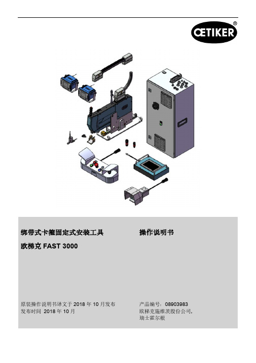
绑带式卡箍固定式安装工具欧梯克FAST 3000操作说明书原装操作说明书译文于2018年10月发布发布时间2018年10月产品编号:08903983欧梯克施维茨股份公司,瑞士霍尔根欧梯克FAST 3000目录目录1.本手册简介 .................................................................................................................................................... 1-81.1所用符号和对应含义............................................................................................................................. 1-81.2范围 ...................................................................................................................................................... 1-91.2.1FAST 3000............................................................................................................................... 1-91.2.2铭牌 ....................................................................................................................................... 1-101.3缩写 .................................................................................................................................................... 1-101.4FAST 3000标贴 ..................................................................................................................................1-111.5相关文档............................................................................................................................................. 1-122.基本安全说明............................................................................................................................................... 2-132.1使用操作说明书 .................................................................................................................................. 2-132.2预期目的用途...................................................................................................................................... 2-132.3一般安全说明...................................................................................................................................... 2-142.4盖板 .................................................................................................................................................... 2-162.5特殊安全说明...................................................................................................................................... 2-162.6工作的安全方法 .................................................................................................................................. 2-172.7通过外部控制系统使用FAST 3000 .................................................................................................... 2-172.8改造和改装 ......................................................................................................................................... 2-172.9合格人员............................................................................................................................................. 2-182.10维护工作............................................................................................................................................. 2-202.11压接切割夹紧切断头过载保护 ............................................................................................................ 2-212.12噪声水平............................................................................................................................................. 2-213.FAST 3000工具供货范围............................................................................................................................ 3-223.1FAST 3000主要组件概述................................................................................................................... 3-223.2可用的主要配置 .................................................................................................................................. 3-233.3可选配件............................................................................................................................................. 3-254.FAST 3000简述 .......................................................................................................................................... 4-274.1工具机制工作原理的设计.................................................................................................................... 4-284.2FAST 3000压接切割头的设计............................................................................................................ 4-304.3双手控制台 ......................................................................................................................................... 4-325.FAST 3000过程监控描述............................................................................................................................ 5-33欧梯克FAST 3000目录5.1闭合力控制和工艺参数描述................................................................................................................ 5-335.1.1闭合卡紧力控制功能描述....................................................................................................... 5-345.1.2闭合卡紧力............................................................................................................................. 5-355.1.3闭合卡紧力公差 ..................................................................................................................... 5-355.1.4切换点减小量......................................................................................................................... 5-355.1.5速度阶段1 ............................................................................................................................. 5-355.1.6速度阶段2 ............................................................................................................................. 5-355.1.7闭合卡紧力保持时间.............................................................................................................. 5-355.1.8不同闭合卡紧力参数下的样本曲线 ........................................................................................ 5-365.1.9闭合卡紧力传感器可合理性测试............................................................................................ 5-385.2压接夹紧监控...................................................................................................................................... 5-385.2.1压接夹紧力监控(CFM)一般信息........................................................................................ 5-385.2.2机械设计 ................................................................................................................................ 5-395.2.3CFM:典型的正常受力曲线................................................................................................... 5-425.2.4CFM:磨损检测..................................................................................................................... 5-435.2.5CFM:闭合卡紧操作的样本曲线 ........................................................................................... 5-445.3切断监控............................................................................................................................................. 5-566.FAST 3000的操作....................................................................................................................................... 6-576.1调试 .................................................................................................................................................... 6-576.2控制柜连接 ......................................................................................................................................... 6-596.3压接夹紧力监控的电缆连接................................................................................................................ 6-606.4打开启动FAST 3000.......................................................................................................................... 6-616.5纠正FAST 3000正确的定位 .............................................................................................................. 6-636.5.1定位FAST 3000和翼形锁扣®卡箍外壳锁扣的一般说明....................................................... 6-636.5.2使用对齐位辅助装置定位FAST 3000安装工具 .................................................................... 6-676.5.3正确定位FAST 3000的所需尺寸 .......................................................................................... 6-696.6正常操作(生产)............................................................................................................................... 6-716.7实验室模式(密码保护).................................................................................................................... 6-746.7.1单手操作 ................................................................................................................................ 6-766.7.2脚踏板(Foot pedal) ........................................................................................................... 6-786.8特殊操作模式(密码保护)................................................................................................................ 6-806.8.1解锁 ....................................................................................................................................... 6-816.8.2驱动器的手动模式操作 .......................................................................................................... 6-82欧梯克FAST 3000目录6.8.3将压力补偿设置为零.............................................................................................................. 6-836.8.4验证卡紧力............................................................................................................................. 6-846.8.5夹紧力监控验证 ..................................................................................................................... 6-856.8.6调整夹紧力监控 ..................................................................................................................... 6-876.8.7为CFM装置加载新的设置/测量程序..................................................................................... 6-937.GUI .............................................................................................................................................................. 7-957.1触控板................................................................................................................................................. 7-957.2电脑 .................................................................................................................................................... 7-957.3GUI布局............................................................................................................................................. 7-967.4菜单结构............................................................................................................................................. 7-977.4.1欢迎界面 ................................................................................................................................ 7-977.4.2卡紧数据(更改数值需要密码)............................................................................................ 7-987.4.3操作模式 ................................................................................................................................ 7-997.4.4摩擦测试 .............................................................................................................................. 7-1047.4.5IO测试................................................................................................................................. 7-1057.4.6日志 ..................................................................................................................................... 7-1087.4.7设置 ......................................................................................................................................7-1147.4.8信息 ..................................................................................................................................... 7-1217.4.9错误列表(版本V2.09) ..................................................................................................... 7-1227.4.10访问权限 .............................................................................................................................. 7-1258.分配IP地址............................................................................................................................................... 8-1268.1设定日期和时间 ................................................................................................................................ 8-1279.部件维护和更换 ......................................................................................................................................... 9-1289.1关于维护和修理工作的一般安全说明................................................................................................ 9-1289.2维护 .................................................................................................................................................. 9-1299.2.1预防性维护工作 ................................................................................................................... 9-1299.2.2维护后工作........................................................................................................................... 9-1299.2.3定期检查状态....................................................................................................................... 9-1319.2.4定期维护工作/维护时间表.................................................................................................... 9-1329.2.5A-维护-每100000次循环执行一次...................................................................................... 9-1339.2.6B-维护-每20万次循环执行一次 .......................................................................................... 9-1349.3更换部件........................................................................................................................................... 9-135欧梯克FAST 3000目录9.3.1拆卸夹紧切断头 ................................................................................................................... 9-1369.3.2安装夹紧切断头 ................................................................................................................... 9-1389.3.3更换夹紧钳口和/或切断刀具 ................................................................................................ 9-1389.3.4更换夹紧楔形件 ................................................................................................................... 9-1429.3.5更换夹紧钳口轴销................................................................................................................ 9-1429.3.6更换夹紧杆........................................................................................................................... 9-1449.4检查和调整条带检测传感器的位置 ................................................................................................... 9-1479.5设置卡紧力传感器............................................................................................................................. 9-1499.5.1调整测力传感器 ................................................................................................................... 9-1499.6更换控制柜或工具机构 ..................................................................................................................... 9-1509.7维护工具和耗材 ................................................................................................................................ 9-15110.通过外部PLC控制FAST 3000............................................................................................................... 10-15810.1通过现场总线(以太网/IP或Profinet)进行控制........................................................................... 10-15810.1.1设置以太网/IP通信协议..................................................................................................... 10-15810.1.2设置Profinet HW配置....................................................................................................... 10-15910.1.3现场总线映射(软件版本V2.09)..................................................................................... 10-15910.2通过24伏I/O信号控制.................................................................................................................. 10-16311.停用、运输、储存、重新投入使用.......................................................................................................... 11-16411.1停用 .................................................................................................................................................11-16411.2运输 .................................................................................................................................................11-16411.3存储 .................................................................................................................................................11-16611.4重新调试..........................................................................................................................................11-16611.5处理 .................................................................................................................................................11-16612.技术数据.................................................................................................................................................. 12-16713.故障排除和错误消息................................................................................................................................ 13-16813.1错误情形一般说明........................................................................................................................... 13-16813.2如果……,我应该怎么办?............................................................................................................ 13-16813.3错误消息及其解决方案 ................................................................................................................... 13-17213.3.1ToErr_1: (W)存在条带-> 移除并确认......................................................................... 13-17213.3.2ToErr_2: 夹紧装置不在初始位置STO -> 初始化............................................................. 13-17313.3.3PrErr_1: 超过最大张紧行程 .............................................................................................. 13-17413.3.4PrErr_11: 夹紧的一般错误 ................................................................................................ 13-175欧梯克FAST 3000目录13.3.5PrErr_12: 切断错误........................................................................................................... 13-17613.3.6ToErr_4: 位置传感器失效.................................................................................................. 13-17613.3.7PrErr_15: 卡紧力超出公差................................................................................................ 13-17713.3.8警告2:按钮接触出错 ....................................................................................................... 13-17713.3.9ToErr_5: 驱动器激活错误.................................................................................................. 13-17813.3.10ToErr_6: 紧急停止电路打开/ 工具错误_14:紧急停止................................................... 13-17813.3.11PrErr_3: 夹紧错误CFM1包络曲线1................................................................................ 13-17913.3.12PrErr_4: 夹紧错误CFM1包络曲线2................................................................................ 13-17913.3.13PrErr_5: 夹紧错误夹紧CFM1未通过............................................................................... 13-17913.3.14PrErr_6: 夹紧误差CFM1磨损.......................................................................................... 13-17913.3.15PrErr_7: 夹紧错误CFM2包络曲线1................................................................................ 13-17913.3.16PrErr_8: 夹紧错误CFM2包络曲线2................................................................................ 13-18013.3.17PrErr_9: 夹紧错误CFM2未通过 ...................................................................................... 13-18013.3.18PrErr_10: 夹紧误差CFM2磨损........................................................................................ 13-18013.3.19过程错误_13 力过度 ......................................................................................................... 13-18013.3.20过程错误_16 光幕在被遮挡时的最大力 ............................................................................ 13-18113.3.21PrErr_17: 到达排料位置的最大力 ..................................................................................... 13-18213.3.22PrErr_18: 过程中止........................................................................................................... 13-18213.3.23PrErr_19: 在总线停止时中断时的最大力 .......................................................................... 13-18213.3.24ToErr_7: 光幕在初始化程序中激活 ................................................................................... 13-18213.3.25ToErr_8: 验证夹紧力(阶段1)........................................................................................ 13-18313.3.26ToErr_9: 验证夹紧力(阶段2)........................................................................................ 13-18313.3.27ToErr_10: 验证夹紧力:没有力增加 ................................................................................. 13-18413.3.28ToErr_11: 检查条带废料.................................................................................................... 13-18413.3.29ToErr_12: CFM一般警告/错误 .......................................................................................... 13-18413.3.30工具错误_13 检查张紧力传感器 ....................................................................................... 13-18513.3.31工具错误_16 操作过程中无电源 ....................................................................................... 13-18613.3.32警告_1 确认错误 ............................................................................................................... 13-18613.3.33警告_3 无电源- 按下开始-> 初始化.............................................................................. 13-18613.3.34警告_4 CFM装置警告/错误............................................................................................... 13-18613.3.35警告_5 维护即将到期........................................................................................................ 13-18713.3.36警告_6 维护到期 ............................................................................................................... 13-18713.3.37警告_7 光幕触发的停机 .................................................................................................... 13-18713.3.38警告_8 CFM示教模式激活................................................................................................ 13-187欧梯克FAST 3000目录13.3.39警告_9 工具无电源 ........................................................................................................... 13-18813.3.40警告_10 无外部电源激活,按下“启动”............................................................................ 13-18813.3.41警告_11 移除条带 ............................................................................................................. 13-18914.附录 ......................................................................................................................................................... 14-190欧梯克FAST 3000本手册简介1. 本手册简介1.1 所用符号和对应含义本手册使用安全标志警示人身伤害或财产损失风险。
德国kado纠偏操作手册

AE 500纠偏系统控制器简明操作手册基本信息本手册中描述的是AE 500物料纠偏控制器的操作和显示界面,以及重要的操作步骤。
使用AE 500物料纠偏控制器前,务必了解相关操作方法,以避免危险和因不正确安装或操作而引起的系统损坏。
在对AE 500物料纠偏控制器进行调试和维护保养前,务必阅读使用说明书中的安全提示!本手册中所给出的数据仅用于举例(例如显示屏上的图示),另有说明的除外。
目录第一部分:操作面板1.1面板布局·······································4 1.2键盘功能·······································5 第二部分:操作模式选择 2.1 手动操作设定..................................6 2.2 自动操作设定..................................6 2.3 纠偏框架回中. (6)第三部分:控制器增益值设置3.1 控制器增益值调整 (7)第四部分:物料设置4.1自动传感器设定·······························8-94.2手动传感器设定································10 4.3定中自动传感器设定····························11 4.4定中手动传感器设定····························12 4.5 驱动器设定 (13)4.6版本显示······································14 4.7电机方向设5.1 电源接线····································16 5.2 传感器接线··································17-18第一部分:1.1面板布局1.2键盘功能功能按键描述操作模式选择手动纠偏模式自动纠偏模式框架回中模式定左单边纠偏定右单边纠偏对中纠偏纠偏模式选择﹢纠偏辊架的手动定位设置菜单在手动定位模式下手动将框架向左、向右移动在手动定位模式下进入“设置”菜单“保存”键“返回”键增益调整菜单纠偏盲区调整在自动定位模式下增益增加或者减小在自动定位模式下减小-增加纠偏盲区数值第二部分:操作模式选择2.1手动操作设定使用“手动定位模式”对纠偏辊架的位置进行手动调整。
德国kado纠偏操作手册

AE 500 纠偏系统控制器简明操作手册基本信息本手册中描述的是AE 500物料纠偏控制器的操作和显示界面,以及重要的操作步骤。
使用AE 500物料纠偏控制器前,务必了解相关操作方法,以避免危险和因不正确安装或操作而引起的系统损坏。
在对AE 500物料纠偏控制器进行调试和维护保养前,务必阅读使用说明书中的安全提示!本手册中所给出的数据仅用于举例(例如显示屏上的图示),另有说明的除外。
目录第一部分:操作面板1.1面板布局·······································4 1.2键盘功能·······································5 第二部分:操作模式选择 2.1 手动操作设定..................................6 2.2 自动操作设定..................................6 2.3 纠偏框架回中. (6)第三部分:控制器增益值设置3.1 控制器增益值调整 (7)第四部分:物料设置4.1自动传感器设定·······························8-94.2手动传感器设定································10 4.3定中自动传感器设定····························11 4.4定中手动传感器设定····························12 4.5 驱动器设定 (13)4.6版本显示······································14 4.7电机方向设5.1 电源接线····································16 5.2 传感器接线··································17-18第一部分:1.1面板布局1.2键盘功能功能按键描述操作模式选择手动纠偏模式自动纠偏模式框架回中模式定左单边纠偏定右单边纠偏对中纠偏纠偏模式选择﹢纠偏辊架的手动定位设置菜单在手动定位模式下手动将框架向左、向右移动在手动定位模式下进入“设置”菜单“保存”键“返回”键增益调整菜单纠偏盲区调整在自动定位模式下增益增加或者减小在自动定位模式下减小-增加纠偏盲区数值第二部分:操作模式选择2.1手动操作设定使用“手动定位模式”对纠偏辊架的位置进行手动调整。
上海凯多(德国KADO)宣传册-纠偏、测厚、视觉、测宽系统

纠偏机构立即对物料的位置进行精确纠偏。
纠偏模式
纠偏模式的选取取决于客户的生产工艺;
主要的纠偏模式有以下几种
AE500控制器
AE 500控制器是一种经济型的控制器,它可以实现自动纠偏系统所需的各种基本任务。控制器的安装设
GR12/100/2.5/20×4 / CX
500N
20mm/s
100mm
121005
GR12/200/5/20×4 / CX
1000N
10mm/s
200mm
121002
GR12/200/2.5/20×4 / CX
500N
20mm/s
200mm
121006
GR13
特殊性能:
24V DC直流(控制器供电)
超声波传感器
特性:
1、对灰尘及物料透明度变化不敏感。
2、在传感器的扫描范围内,物料厚度的变化不会引起测
量值的变化。
3、线性扫描范围较大,在物料幅宽变化相对较大的情况
下,也可以实现定中心线纠偏。
4、能够补偿因外部噪声等环境影响所产生的干扰。
参数:
型号:(Model) US2014/50
工作电压:U:±12V
工作电压:U:±12V
测量范围:(Measuring range) ±12.5mm(25mm)
检测精度:(Accuracy)0.01mm
开口距离:(Opening distance) 50mm
输出:(Output)±0-10V模拟量
防护等级:(Protection)IP54
环境温度:(Temperature)0-60℃
德国EL纠偏导正系统DRS1202使用说明书

德国EL纠偏导正系统DRS1202使用说明书
德国XX纠偏导正系统XXX操作使用说明书如下:
①功能:用于幅材张力控制的称重传感器包括一个带有法兰盖的稳定外圈和用于精密装配的定心环。
双向带形式的内国确保球轴承的中心安装。
腹板产生的径向力使连接在一起的应变计失去平衡在内圈上形成测量桥。
这导致模拟输出信号与幅材张力成正比。
②使用范围:法兰称重传感器可用于在几乎所有处理或整理幅材类材料的加工厂中进行幅材张力控制。
特别是在加工站前以连续的幅材张力输送幅材至关重要。
③应用层面:通过测量辊上90°的水平垂直包角和水平测量方向确保最佳的幅材张力测量。
只有通过张力传感器检测两侧的承载力才能防止因幅材侧向移动和幅材张力分布不对称而导致的测量错误。
集成在闭环中的称重传感器应安装在尽可能靠近执行器的位置。
④使用张力传感器可靠地控制幅材张力有助于减少幅材撕裂从
而降低生产成本。
ELTENS幅材张力测量和控制系统在世界各地得到使用以实现可靠和高质量的生产。
- 1、下载文档前请自行甄别文档内容的完整性,平台不提供额外的编辑、内容补充、找答案等附加服务。
- 2、"仅部分预览"的文档,不可在线预览部分如存在完整性等问题,可反馈申请退款(可完整预览的文档不适用该条件!)。
- 3、如文档侵犯您的权益,请联系客服反馈,我们会尽快为您处理(人工客服工作时间:9:00-18:30)。
AE 500纠偏系统控制器简明操作手册基本信息本手册中描述的是AE 500物料纠偏控制器的操作和显示界面,以及重要的操作步骤。
使用AE 500物料纠偏控制器前,务必了解相关操作方法,以避免危险和因不正确安装或操作而引起的系统损坏。
在对AE 500物料纠偏控制器进行调试和维护保养前,务必阅读使用说明书中的安全提示!本手册中所给出的数据仅用于举例(例如显示屏上的图示),另有说明的除外。
目录第一部分:操作面板1.1面板布局·······································4 1.2键盘功能·······································5 第二部分:操作模式选择 2.1 手动操作设定..................................6 2.2 自动操作设定..................................6 2.3 纠偏框架回中. (6)第三部分:控制器增益值设置3.1 控制器增益值调整 (7)第四部分:物料设置4.1自动传感器设定·······························8-94.2手动传感器设定································10 4.3定中自动传感器设定····························11 4.4定中手动传感器设定····························12 4.5 驱动器设定 (13)4.6版本显示······································14 4.7电机方向设5.1 电源接线····································16 5.2 传感器接线··································17-18第一部分:1.1面板布局1.2键盘功能功能按键描述操作模式选择手动纠偏模式自动纠偏模式框架回中模式定左单边纠偏定右单边纠偏对中纠偏纠偏模式选择﹢纠偏辊架的手动定位设置菜单在手动定位模式下手动将框架向左、向右移动在手动定位模式下进入“设置”菜单“保存”键“返回”键增益调整菜单纠偏盲区调整在自动定位模式下增益增加或者减小在自动定位模式下减小-增加纠偏盲区数值第二部分:操作模式选择2.1手动操作设定使用“手动定位模式”对纠偏辊架的位置进行手动调整。
1.进入“手动定位模式”。
或者 2. 移动纠偏辊架至所需的位置。
2.2自动操作设定使用“自动纠偏模式”进行定单边或定中心线的自动纠偏。
1.选择所需的纠偏模式:定左单边纠偏(传感器1)定右单边纠偏(传感器2)+ 定中纠偏。
2.进入“自动纠偏模式”。
2.3纠偏框架回中使用“纠偏辊架回中”移动纠偏辊架至设定的中心位置。
移动纠偏辊架至设定的中心位置。
第三部分:控制器增益值设置一般情况下,控制器的增益值只须在初始化时设置一次。
在运行过程中如果发生纠偏辊架颤动,可以按照以下流程对控制器的增益值进行优化调整。
使用“自动纠偏模式”进行系统的增益设置。
进入“自动纠偏模式”或者按“+”或者“—”增加/减小控制器的增益值,直至稳定。
第四部分:物料设置设定物料时,控制器将自动按照待纠偏物料的特性(例如:使用红外线传感器时不同物料的透明度,或使用超声波传感器时不同物料的超声波吸收率等)进行适配。
物料的设定可以选择自动或手动操作。
“自动物料设定”用于正常情况下传感器的亮/暗值的设定。
“手动物料设定”用于需要对特殊对比度进行采样的情况。
亮值/暗值的生成:亮值保持传感器的测量窗完全没有被遮盖,即传感器测量围没有物料。
暗值待纠偏物料完全遮盖传感器的测量窗。
4.1自动传感器设定1、将物料移出传感器围,清洁传感器的测量窗。
2、选择左传感器或者右传感器。
3.进入“设置”菜单。
或4、在“设置”菜单中选择“自动物料设定”5、按照显示器中动画的提示,完全敞开选传感器的测量窗,测得的亮值将显示在显示屏上。
6、按照显示器中动画的提示,用待纠偏物料完全遮盖住所选传感器的测量窗,并保持约 2秒钟,测得的暗值将显示在显示屏上。
7、按“保存”键,保存测得的暗值和亮值。
所选传感器的物料设定结束。
4.2手动传感器设定1、将物料移出传感器围,清洁传感器的测量窗。
2、选择左传感器或者右传感器。
3.进入“设置”菜单。
4、在“设置”菜单中选泽“手动物料设定”5、按照显示器中动画的提示,完全敞开所选传感器的测量窗,测得的亮值将显示在显示屏上。
6、按“保存”键,切换到暗值的学习。
7、按照显示器中动画的提示,用待纠偏物料完全遮盖住所选传感器的测量窗,并保持约2秒钟,待测得的暗值稳定的显示在显示屏上。
8、按“保存”键,保存测得的暗值和亮值。
所选传感器的物料设定结束。
4.3对中传感器自动设定1、将物料移出传感器围,清洁传感器的测量窗。
2、选择传感器。
3.进入“设置”菜单。
4、在“设置”菜单中选泽“自动物料设定”5、按照显示器中动画的提示,完全敞开所选传感器的测量窗,测得的亮值将显示在显示屏上。
6、按照显示器中动画的提示,用待纠偏物料完全遮盖住所选传感器的测量窗,并保持约2秒钟测得的暗值将显示在显示屏上。
7、完全敞开传感器2的测量窗,测得的亮值将显示在显示屏上。
8、用待纠偏物料完全遮盖住传感器2测量窗,并保持约2秒钟,测得的暗值将显示在显示屏上。
9、按“保存”键,保存传感器2测得的暗值和亮值。
物料设定完成4.4对中传感器手动设定1、将物料移出传感器围,清洁传感器的测量窗。
+ 2、选择左传感器和右传感器3.进入“设置”菜单。
4、在“设置”菜单中选泽“手动物料设定”5、按照显示器中动画的提示,完全敞开所选传感器的测量窗,测得的亮值将显示在显示屏上。
6、按照显示器中动画的提示,用待纠偏物料完全遮盖住所选传感器的测量窗,并保持约2秒钟,测得的暗值将显示在显示屏上。
7、按“保存”键,保存传感器1测得的暗值和亮值。
8、完全敞开传感器2的测量窗,测得的亮值将显示在显示屏上。
9、用待纠偏物料完全遮盖住传感器2测量窗,并保持约2秒钟,测得的暗值将显示在显示屏上。
10、按“保存”键,保存传感器2测得的暗值和亮值。
物料设定完成4.5驱动器设定1. 进入“手动定位模式”2、进入“设置”菜单,显示3、选择“驱动器设置”菜单,界面显示:执行器最大行程的设置:4、按住,执行器应向传感器 1 方向移动,当电机堵转标志()变成红色时()或执行器不能再移动时,说明执行器走到了左极限位置。
5、此时按下6、此时按着,按钮变成,记录左极限位置。
按钮,执行器向传感器2 的方向移动,当电机堵转标志()变成红色时()或执行器不能再移动时,说明执行器走到了右极限位置。
7、此时按下8、按下,按钮变成,记录右极限位置。
按钮,保存执行器最大行程的设置。
自定义行程的设置:9、在最大行程设定完成后,重复步骤4、5、6、7、8可进行自定义行程的设置。
自定义的行程总小于或等于执行器的最大行程。