AT868简易操作手册
AUREL RTX5MID868 FSK OOK RF数码通信模块用户手册说明书
Blocking test at ± 10MHz
To Be Defin.
dB
See note 3
Image frequency rejection
To Be Defin.
dB
See note 2
Output square wave
0,05
1
3
KHz
Input square wave
0,01
3
kHz
RSSI (pin 8)
AUR.EL RTX-MID-868-FSK
AUR.EL RTX-MID-868-OOK
---------------------------------------------------------------------------------------------------------------------------------------------------来自-109-111
dBm
RF irradiated power (OOK and FSK)
7
8,5
10
dBm
FSK ∆F deviation
±25
KHz
See note 1
OOK Modulation
100
%
Blocking test at ± 2MHz
To Be Defin.
dB
See note 3
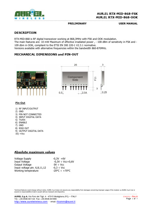
MECHANICAL DIMENSIONS and PIN-OUT
Pin-Out
1) RF INPUT/OUTPUT 2) GND 3) PIN NOT CONNECTED 4) INPUT DIGITAL DATA 5) TX/RX 6) ENABLE 7) GND 8) RSSI OUT 9) OUTPUT DIGITAL DATA 10) +Vcc
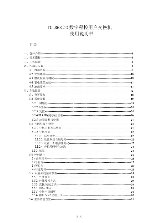
TCL868数字程控用户交换机 说明书
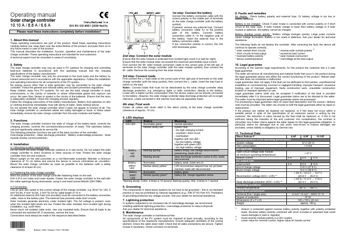
太阳能充电控制器操作手册说明书
Operating manualSolar charge controller10.10 A / 8.8 A / 6.6 APlease read these instructions completely before installation!1. About this manualThese operating instructions are part of the product. Read these operating instructions carefully before use, keep them over the entire lifetime of the product, and pass them on to any future owner or user of this product.This manual describes the installation, function, operation and maintenance of the solar charge controller. These operating instructions are intended for end customers.A technical expert must be consulted in cases of uncertainty.2. SafetyThe solar charge controller may only be used in PV systems for charging and controlling lead-acid batteries in accordance with this operating manual and the charging specifications of the battery manufacturer.The solar charge controller may only be connected to the local loads and the battery by trained personnel and in accordance with the applicable regulations. Follow the installation and operating instructions for all components of the PV system.No energy source other than a solar generator may be connected to the solar charge controller. Follow the general and national safety and accident prevention regulations.Keep children away from PV systems. Do not use the solar charge controller in dusty environments, in the vicinity of solvents or where inflammable gases and vapours can occur. No open fires, flames or sparks in the vicinity of the batteries. Ensure that the room is adequately ventilated. Check the charging process regularly.Follow the charging instructions of the battery manufacturer. Battery Acid splashes on skin or clothing should be immediately rinse with plenty of water. Seek medical advice.Do not operate the solar charge controller when it does not appear to function at all. The solar charge controller or connected cables are visibly damaged or loose. In these cases immediately remove the solar charge controller from the solar modules and battery.3. FunctionsThe solar charge controller monitors the state of charge of the battery bank, controls the charging process, controls the connection/disconnection of loads. This optimises battery use and significantly extends its service life.The following protection functions are part of the basic function of the controller: Overcharge protection ; Deep discharge protection ; Battery undervoltage protection ; Solar module reverse current protection.4. Installation4.1 Mounting location requirementsDo not mount the solar charge controller outdoors or in wet rooms. Do not subject the solar charge controller to direct sunshine or other sources of heat. Protect the solar charge controller from dirt and moisture.Mount upright on the wall (concrete) on a non-flammable substrate. Maintain a minimum clearance of 10 cm below and around the device to ensure unhindered air circulation. Mount the solar charge controller as close as possible to the batteries (with a safety clearance of at least 30 cm).4.2 Fastening the solar charge controllerMark the position of the solar charge controller fastening holes on the wall.Drill 4 Ø 6 mm holes and insert dowels. Fasten the solar charge controller to the wall with the cable openings facing downwards, using 4 oval head screws M4x40 (DIN 7996).4.3 ConnectionUse an wire size suited to the current ratings of the charge controller, e.g. 6mm² for 10A, 5 mm² for 8A, 4 mm² for 6A, 3 mm² for 5A for cable length of 10 m.An additional external 20A fuse (not provided) must be connected to the battery connection cable, close to the battery pole. The external fuse prevents cable short circuits.Solar modules generate electricity under incident light. The full voltage is present, even when the incident light levels are low. Protect the solar modules from incident light during installation, e.g. cover them.Never touch not isolated cable ends. Use only insulated tools. Ensure that all loads to be connected are switched off. If necessary, remove the fuse.Connections must always be made in the sequence described below.1st step: Connect the batteryConnect the battery connection cable with thecorrect polarity to the middle pair of terminalson the solar charge controller (with the batterysymbol).If present, remove any external fuse. Connectbattery connection cable A+ to the positivepole of the battery. Connect batteryconnection cable A– to the negative pole ofthe battery. Insert the external fuse in thebattery connection cable.If the connection polarity is correct, the infoLED illuminates green.2nd step: Connect the solar moduleEnsure that the solar module is protected from incident light (cover it or wait for night).Ensure that the solar module does not exceed the maximum permissible input current.First connect the M+ solar module connection cable to the correct pole of the left pair ofterminals on the solar charge controller (with the solar module symbol), then connect theM– cable. Remove the covering from the solar module.3rd step: Connect loadsFirst connect the L+ load cable to the correct pole of the right pair of terminals on the solarcharge controller (with the lamp symbol), then connect the L– cable. Insert the load fuse orswitch on the load.Notes : Connect loads that must not be deactivated by the solar charge controller deepdischarge protection, e.g. emergency lights or radio connection, directly to the battery.Loads with a higher current consumption than the device output can be directly connectedto the battery. However, the solar charge controller deep discharge protection will no longerintervene. Loads connected in this manner must also be separately fused.4th step: Final workFasten all cables with strain relief in the direct vicinity of the solar charge controller(clearance of approx. 10 cm).5. LED displaysLED Status Meaningilluminates green normal operationInfo LEDflashes slowly red* system fault- too high charging current- overload / short circuit- overheatedtogether with red LED :- too low battery voltagetogether with green LED :- too high battery voltageflashing quickly* battery empty, low voltage disconnectionprewarning, loads still onBatteryredLED flashing slowly* deep discharge protection active (LVD), loadsdisconnectedilluminates battery weak, loads are onBatteryyellowLEDflashes slowly yellow* LVD reconnection setpoint has not yet beenreached, loads still disconnectedilluminates battery goodBatterygreenLEDflashes quickly green* battery full, charge regulation active*flashing slowly: 0,4Hz: 4 times in 10 second, flashing quickly: 3Hz: 3 times in 1 second6. GroundingThe components in stand-alone systems do not have to be grounded – this is not standardpractice or may be prohibited by national regulations (e.g.: DIN 57100 Part 410: Prohibitionof grounding protective low voltage circuits). Ask your dealer for technical assistance.7. Lightning protectionIn systems subjected to an increased risk of overvoltage damage, we recommendinstalling additional lightning protection / overvoltage protection to reduce dropouts.Ask your dealer for technical assistance.8. MaintenanceThe solar charge controller is maintenance-free.All components of the PV system must be checked at least annually, according to thespecifications of the respective manufacturers. Ensure adequate ventilation of the coolingelement. Check the cable strain relief. Check that all cable connections are secure. Tightenscrews if necessary. Check corrosion on terminals.9. Faults and remediesNo display : Check battery polarity and external fuse. Or battery voltage is too low orbattery defective.Battery is not charged : Check if solar modul is connected with correct polarity or if shortcircuit at the solar input. If solar module voltage is lower than battery voltage or if solarmodule is defective the battery cannot be charged.Battery displays jumps quickly : Battery voltage changes quickly. Large pulse currentscause voltage fluctuation. Battery is too small or defective. Ask your dealer for technicalassistance.The following faults do not destroy the controller. After correcting the fault, the device willcontinue to operate correctly:* solar module short circuits * reverse solar module polarity *2* short circuits at load output * excessive load current* reversed battery polarity *1* solar module overcurrent* device overtemperature * overvoltage at the load output10. Legal guaranteeAccording to the German legal requirements, for this product the customer has a 2 yearlegal guarantee.The seller will remove all manufacturing and material faults that occur in the product duringthe legal guarantee period and affect the correct functioning of the product. Natural wearand tear does not constitute a malfunction.Legal guarantee does not apply if the fault can be attributed to third parties, unprofessionalinstallation or commissioning, incorrect or negligent handling, improper transport, excessiveloading, use of improper equipment, faulty construction work, unsuitable constructionlocation or improper operation or use.Legal guarantee claims shall only be accepted if notification of the fault is providedimmediately after it is discovered. Legal guarantee claims are to be directed to the seller.The seller must be informed before legal guarantee claims are processed.For processing a legal guarantee claim an exact fault description and the invoice / deliverynote must be provided. The seller can choose to fulfil the legal guarantee either by repair orreplacement.If the product can neither be repaired nor replaced, or if this does not occur within asuitable period in spite of the specification of an extension period in writing by thecustomer, the reduction in value caused by the fault shall be replaced, or, if this is notsufficient taking the interests of the end customer into consideration, the contract iscancelled. Any further claims against the seller based on this legal guarantee obligation, inparticular claims for damages due to lost profit, loss-of-use or indirect damages areexcluded, unless liability is obligatory by German law.11. Technical DataSteca Solsum F 6.6F 8.8F 10.10FSystem voltage 12 V (24 V)Own consumption < 4 mADC input sideOpen circuit voltage solar module(at minimum operating temperature)< 47 VModule current 6 A 8 A 10 ADC output sideLoad current 6 A 8 A 10 AEnd of charge voltage 13.9 V (27.8 V)Boost charge voltage 14.4 V (28.8 V)Reconnection voltage (SOC / LVR) *³> 50 % / 12.4 V … 12.7 V(24.8 V … 25.4 V)Deep discharge protection (SOC / LVD) *³< 30 % / 11.2 V … 11.6 V(22.4 V … 23.2 V)Operating conditionsAmbient temperature -25 °C … +50 °CFitting and constructionTerminal (fine / single wire) 4 mm2 / 6 mm2 - AWG 12 / 9Degree of protection IP 32Dimensions (X x Y x Z) 145 x 100 x 24 mmWeight approx. 150 g*1Solsum is protected against reverse battery polarity together with polarity protectedloads. Reverse battery polarity combined with short circuited or polarised load couldcause damages in load or regulator*2Avoid reverse module polarity in a 24V system*3Lower value for nominal current, higher value for lowest currentInfo LED Battery LEDsManufactured in aDIN EN ISO 9001:2000 facilitySolsum / Z02 / Version 1104/ 730.930。
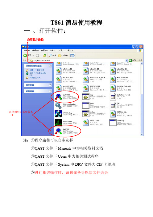
T861简易使用教程
②测试列表 1
注:①进入工程师菜单后首先进入上图界面,首先点击上图 红圈进入 VC 调试台后点击下图中菜单进行编译: 编译完成后程序下方菜单出现如下图所示无错误即可
②函数列表中在测试项目前的绿/红灯可以控制是否测试 该项目
②测试列表 2
开始
测试模式
上下限 视窗
设置
注:①黑色小人为开始键(F2) ②顶端菜单 HANDLER 为测试模式键,可以选择各种测量 模式及工位数,如下图为手测模式下的单工位:
③顶端菜单视窗可以使得界面在测试列表 1 与测试列表 2 之间进行切换(CTRL+TAB),如下图
④功能键 PP 键中主要介绍数据保存以及分 BIN 分 BIN: BIN 设置如下图所示(BIN1-4 为默认良品)
测试机 BIN 良品 废品
分选机 BIN
数据保存如下图所示
自动保存
保存路径
数据保存文件格式
五、操作员菜单(OPERATOR)
注:功能类似于工程师菜单(无法使用部分功能),在这里 不加赘述。
T861 简易使用教程
一 、打开软件:
应用程序路径
选择相应的系统版本
注:①程序路径可以自主选择 ②QA8T 文件下 Manuals 中为相关资料文档 ③QA8T 文件下 Users 中为相关测试程序 ④QA8T 文件下 System 中 DRV 文件为 CIF 卡驱动 ⑤进行相关操作时,请预先备份以防文件丢失
二、系统主界面:
注:默认系统账号与密码均为:Administrator
三、系统操作界面
操作员菜单 工程师菜单 创建菜单 系统菜单பைடு நூலகம்自检菜单 退出
1、 自检菜单(MAINTENANCE)
注:①下方板卡信息表中 SLOT 为槽位,ACT 为实际在位板卡, CFG 为系统配置板卡(可自定义)
健伍TK-808(868)的设置与实用功能开发
健伍TK-808(868)的设置与实⽤功能开发 TK-808系列是KENWOOD公司出品的专业车载电台,可存储16个频道,具有体积⼩巧、操作简单、坚固耐⽤的特点。
该系列产品有TK-808(25W)和TK-808H(35W)两⼤类,后缀带有字母“H”的型号具有⾼功率35W输出。
作为专业电台TK-808按照指标保证频段分为⾼段机M(450-470MHz)和低段机M4(400-420MHz),但通过简单的调试都可以很好的⼯作在430-440MHz业余波段中。
KENWOOD TK-808属于专业电台,所以要求在使⽤前由专业⼈员为⽤户设置好通讯频率,使⽤户操作尽量简单,减少误触动可能带来的影响通讯的可能。
对于业余⽆线电爱好者来说这样⼀来留给⽤户⾯板操作功能就⽐较少,在使⽤前必须预先设置,接下来就先简要介绍TK-808系列的设置。
该机为了防⽌⽤户误动对于编程和菜单设置功能可以通过机内跳线加以限制。
打开机盖机内靠前⾯板侧有⼀组CN7跳线,短接左侧两个端⼦(SET侧)为设置模式,短接右侧两个端⼦(USE侧)为⽤户模式,⽤户模式下禁⽌编程。
如果要将TK-808送交国家⽆委验机就必须处于⽤户模式。
实际上TK-808长期处于设置模式下也不影响性能,反⽽给业余⽆线电爱好者设置频率带来⽅便,⽆需频繁的打开机盖。
TK-808频率的设置 在设置模式下按住前⾯板上“CALL”键开机就可以看到⼀频道的接收频率,如果没有看到具体频率依然显⽰ch符号则检查机器是否处于设置模式。
Tk-808的频率设置依次是设置接收频率è设置接收亚⾳编码(如果安装TSU-7组件)è设置发射频率(屏幕上显⽰发射的箭头)è设置发射亚⾳编码。
设置项⽬的确定是通过按PTT键确认。
在很多专业机中没有像业余机采⽤“差频”的概念⽽是采⽤收发频率分开设置,可以适⽤不同的应⽤场合。
TK-808在设置接收频率时通过按“SCAN”键在屏幕上可以出现或消除“ADD”的标记,该标记表⽰当前信道被列⼊扫描列表,也就是说如果某⼀信道没有“ADD”标记以后将不参与扫描。
AT868简易操作手册
GE PANAMETRICS超音波流量計AT868中文操作說明巨路國際(股) 公司LUMAX INTERNATIONAL CORT., LTD.台北公司:台北市南港區園區街3之1號12樓TEL : (02)2788-3656(代表號)FAX : (02)2788-7369AT868主機設定操作手冊按 ESC ENTER ESC 進入PROGRAM。
PROGRAM CALIB RESET 按左右選擇PROGRAM按ENTER;下一選項有CH GLOBL。
※選擇CH進入下一選項 ACTIV SYSTEM PIPE I/O SETUP。
一、選擇ACTIV按ENTER進入,再選擇主機測量模式,一般選TRANS。
回※號二、選擇SYSTEM 按ENTER進入(如單位設定為英制,請先進入GLOBL改成公制);1. 設定CHANNEL LABEL及SITE/CHANNEL MESSAGE等名稱,確定後按ENTER。
2. 按左右選擇流量單位種類如L/S L/M L/H ML/D等,確定後按ENTER。
3. 按左右選擇流量數值小數點,確定後按ENTER。
4. 按左右選擇累積量單位種類如L ML M3等,確定後按ENTER。
5. 按左右選擇累積量數值小數點,確定後按ENTER。
回※號三、選擇PIPE按ENTER進入,1.選擇TRANSDUCER NUMBER按ENTER。
2.選擇PIPE MATERIAL種類,確定後按ENTER。
3.KEY IN PIPE OD,並選擇單位如mm m mm/PI m/PI,確定後按ENTER。
4. KEY IN PIPE WALL,確定後按ENTER。
5.設定有否LINING,確定後按ENTER。
6.設定TRACKING WINDOW(一般為OFF),確定後按ENTER。
7.設定FLUID TYPE,確定後按ENTER。
8.設定REYNOLDS CORRECTION(如FLUID TYPE是WATER就設ACTIV並選擇STATC此時主機會自動顯示REYNOLDS CORRECTION),確定後按ENTER。
TCL868说明书

pci08/pci16用户操作手册(for windows 2000/xp)tcl 8.9.92010年05月01日目录第一章系统简述 ----------------------------------------------------------11.1基本功能 ------------------------------------------------------ 1 1.2性能特点------------------------------------------------------ 1 1.3录音方式1.4技术参数------------------------------------------------------11.5硬件配置------------------------------------------------------2------------------------------------------------------2第二章系统安装 ----------------------------------------------------------32.1系统配置 ------------------------------------------------------ 3 2.2语音卡硬件安装 ------------------------------------------------ 3 2.3语音卡驱动程序安装-------------------------------------------- 3 2.4录音系统软件安装----------------------------------------------4第三章录音系统使用说明--------------------------------------------------53.1系统主界面 ---------------------------------------------------- 5 3.2系统管理------------------------------------------------------11 3.2.1系统参数设置----------------------------------------------11 3.2.2 用户信息设置通道姓名设置----------------------------------------------13 3.2.3----------------------------------------------133.2.4通道参数设置 ----------------------------------------------143.2.5数据库管理 ------------------------------------------------213.2.6操作日志管理 ----------------------------------------------213.2.7关闭录音系统 ----------------------------------------------223.3录音管理 --------------------------------------------------------223.3.1查询录音 --------------------------------------------------233.3.2备份录音文件 ----------------------------------------------243.3.3查询留言 --------------------------------------------------253.3.4播放语音文件 ----------------------------------------------263.3.5转换语音文件格式------------------------------------------263.3.6查询未接来电 ----------------------------------------------273.3.7设置过滤电话信息------------------------------------------283.3.8查询过滤电话呼叫------------------------------------------283.3.9统计呼入呼出通话量---------------------------------------- 293.4操作员管理 ------------------------------------------------------293.4.1修改操作员密码 --------------------------------------------303.4.2增加删除操作员 --------------------------------------------303.5客户资料管理 ----------------------------------------------------313.5.1客户资料管理 ----------------------------------------------323.5.2客户沟通记录 ----------------------------------------------323.6交换机管理 ------------------------------------------------------333.6.1私有交换机参数设置 ----------------------------------------333.6.2显示交换机的原始话单数据 ----------------------------------343.6.3显示交换机外线名称设置 ------------------------------------35第四章远端电话查询、远端电话监听、呼入报号、留言功能介绍 -----------------364.1远端电话查询 ----------------------------------------------------36 4.2远端电话监听 ----------------------------------------------------36 4.3呼入报号留言功能功能 ----------------------------------------------------36 4.4--------------------------------------------------------36第五章网络录音留言管理和客户信息管理--------------------------------------375.1登陆录音系统服务器 -----------------------------------------------37 5.2录音管理---------------------------------------------------------375.2.1、网络录音查询和留言查询 -----------------------------------375.2.2、网络留言查询 ---------------------------------------------385.2.3、网络监听 -------------------------------------------------395.3客户信息管理 ----------------------------------------------------405.3.1、客户资料管理 ---------------------------------------------405.3.2、客户沟通记录 ---------------------------------------------405.3.3、弹出客户信息 ---------------------------------------------41第一章简述tcl数字录音系统是我公司根据通信、电力、厂矿、公安、企业、学校、煤矿、个人办公、公司、酒店、证券等行业及其它领域的要求,并结合其应用特点,自主研制并开发的全数字化录音设备。
AT868
AquaTransTM AT868 超声波水流量计(1-& 2- 通道)使用手册GE传感与测量GE 梦想启动未来gGE传感与测量GE 梦想启动未来g 中文网址: 英文网址: E - mail: @ 客户咨询电话:800 915 9966 0411 8366 6489各地办事处上海上海市南京西路1468号中欣大厦5层邮编:200040传真:021 6247 5363武汉武汉市建设大道566号国际商业贸易中心1018室邮编:430022传真:027 8575 8332北京北京市朝阳区光华路7号汉威大厦西区6层邮编:100004传真:010 6561 3315成都成都市总府路2号时代广场B 座20楼2011室邮编:610016传真:028 8665 3854 / 028 8665 3994香港香港铜锣湾希慎道33号利圆15楼传真:852 2100 6663深圳深圳市深南东路5002号信兴广场地王商业大楼3308-11邮编:518008传真:0755 8246 3650乌鲁木齐新疆乌鲁木齐市中山路86号中泉广场12楼B 座邮编:830002传真:0991 2305 200广州广州市建设六马路33号宜安广场1812号邮编:510060传真:020 8363 3876南京南京市汉中路2号金陵饭店世界贸易中心1661室邮编:210005传真:025 8472 8654沈阳沈阳市和平区北大街69号总统大厦C 座907室邮编:110003传真:024 2281 2121郑州郑州市裕达国际贸易中心银座3410室邮编:450007传真:0371 3368 016 西安西安市南大街30号中大国际大厦607室邮编:710002传真:029 8720 3065台北台北市中山区民权东路3段35号7楼邮编:104传真:8862 25055655产品发展有时会涉及技术指标更改,恕不另行通知CH-M-P-027-0512。
GE超声波流量计菜单设置AT868

主要菜单如下1.CHANNEL 1 PARAMETERS:声道1参数设置Channel status Transit----声道1工作状态,transit为时差法2.CHANNEL 1 SYSTEM PARAMETERS:声道1系统参数CHANNEL LABEL CHAN1----声道1标识CHANNEL MESSAGE THIS IS CHAN MESSAGE----声道1信息ENERGY OPTION Off----能量测量VOLUMETRIC UNITS cubic m/hr----声道1体积流量单位VOL DECIMAL DIGITS 1----声道1体积流量小数点位数TOTALIZER UNITS cubic m----声道1累计值单位TOTAL DECIMAL DIGITS 0----声道1累计值小数点位数3.CHANNEL 1 PIPE PARAMETERS:声道1管道参数TRANSDUCER NUMBER 113 Standard----探头编号(401)WEDGE TEMP INPUT Fixed----声楔温度输入方式,fixed为固定温度WEDGE TEMPERATURE 64.0000 deg C----声楔温度PIPE MATERIAL Steel----管道材质,steel钢STEEL Carbon Steel----碳钢PIPE OD 1282.0000 Circum.mm----管道外径,Circum.mm为周长单位为毫米PIPE WALL 12.4499 mm----管壁厚LINING No----管壁内衬情况TRACKING WINDOWS? No----信号跟踪窗口开启情况,信号跟踪窗口适用于管线内传输多种不同介质FLUID TYPE Water----传输介质WATER TEMPERATURE 62.0000 deg C----介质温度REYNOLDS CORRECTION Active----雷诺数修正开启状况(粘度关闭)KV INPUT SELECTION Enter static KV----雷诺数修正值输入方式KINEMATIC VISCOSITY 0.461 E-6 m^2/s----运动粘度值,对于水是自动输入运动粘度的CALIBRATION FACTOR 1.0000----仪表系数NUMBER OF TRAVERSES 1----安装声程数(对面安装为1,同向安装为2)TRANSDUCER SPACING 204.950 mm----仪表显示建议探头安装距离4.CHANNEL 1 INPUT/OUTPUT PARAMETERS:声道1输入/输出参数ZERO CUTOFF 0.0060 m/s----小流量切除5.CHANNEL 1 SETUP PARAMETERS:声道1参数设置SIGNAL LOW LIMIT 40.0----信号低限COR.PEAK LIMIT 100----信号互相关峰值设定,不要改动SOUNDSPEED +- LIMIT 40 percent----信号声速阈值设定VELOCITY LOW LIMIT -12.1920 m/s----流速低限VELOCITY HIGH LIMIT 12.1920 m/s----流速高限ACCELERATION LIMIT 4.5720 m/s----加速度高限AMP. DISCRIM LOW 14----信号放大低限,不要改动AMP. DISCRIM HIGH 34----信号放大高限,不要改动DELTA T OFFSET 0.00 nsec----时间差偏置% of Peak -40 percent----信号检测峰值,不要改动TRANSMITTER VOLTAGE High Voltage----激发电压,不要改动XMIT SAMPLE SIZE 8----发射信号组成,不要改动FORCE HIGH GAIN? No----强制高放大倍数,不要改动# of ERRORS ALLOWED 8----出错报警数设置,不要改动Minimum Peak% limit -100----峰值低限,不要改动Maximum Peak% limit 100----峰值高限,不要改动RESPONSE TIME STATISTICS----响应时间设置Activate Multi K Fact No----多重K系数修正Mass from Static Dens No----质量流量设置Xmit Code Length Automatic----信号编码长度,不要改动11.GLOBAL SYSTEM PARAMETERS:整体参数设置METER MESSAGE THIS IS AN XMT----整体设定信息SYSTEM UNITS metric----系统单位体系VOLUMETRIC UNITS cubic m/hr----体积流量单位VOL DECIMAL DIGITS 1----体积流量小数点TOTALIZER UNITS cubic m----累加值单位TOTAL DECIMAL DIGITS 0----累加值小数点位数MASS FLOW Kilograms----质量流量单位MASS FLOW TIME /sec----质量流量时间单位MDOT DECIMAL DIGITS 0----质量流量小数点位数MASS TOTALS Kilograms----质量累加值单位MASS DECIMAL DIGITS 0----质量累加值小数点位数12.GLOBAL I/O PARAMETERS:整体输入/输出参数设定ERROR HANDLING Force Low----流量计出错时4~20mA输出控制2PATH ERROR HANDLING Yes----第二声道出错控制13.Display:显示设定(菜单:GLOBAL----I/O----LCD)# OF LCD PARAMS 2----显示参数个数(4)1st channel AVG----第一个显示参数对应的声道,AVG表示两声道平均Measurement Name 1 Volumetric----第一个显示参数2nd channel AVG----第二个显示参数对应的声道,AVG表示两声道平均Measurement Name 2 +Total----第二个显示参数,+TOTAL是正向累加值(注:4个显示参数为SS DO/SS UP/SNDSP/VOLUM,其中SS DO和SS UP之间的信号上下限要在50~70之间,如果测量介质为水,SNDSP要达到1500以上)14.GLOBAL COMM PARAMETERS:整体通讯参数Meter Address 1----仪表地址标号BAUD RATE 9600----波特率MODBUS BAUD RATE 9600----ModBus波特率MODBUS PARITY NONE----ModBus奇偶位MODBUS STOP BITS 1----ModBus停止位MODBUS Address 1----ModBus地址15.SLOT 0:模拟输出设置Slot 0 Output A 4-20 mA----模拟输出A口的输出方式Channel Channel 1----输出量对应的通道Measurement Name Volumetric----输出量BASE 0.00 m^3/h----4mA对应的基准量FULL 650.00 m^3/h----20mA对应的满量程量Slot 0 Output B 4-20 mA----模拟输出A口的输出方式Channel Channel 2----输出量对应的通道Measurement Name Volumetric----输出量BASE 0.00 m^3/h----4mA对应的基准量FULL 650.00 m^3/h----20mA对应的满量程量故障诊断和排除在正常情况下,DM不显示任何出错信息(包括E0)。
WIRELESS 868 MHz TEMPERATURE STATION 说明书

42
FUNCTION KEYS: Temperature station: The temperature station has four easy to use function keys.
• DCF time reception ON/OFF
• 24 hour display
• Alarm function with snooze
• Temperature display in degree Celsius (°C)
• Indoor and outdor temperature with MIN/MAX records
+ key • To make adjustment for various settings • Stop the alarm
ALARM key • Enter the alarm setting mode • Switch the alarm ON/ OFF • Stop the alarm
MIN/MAX RESET key • Press and hold to reset the MIN/MAX temperature records • Activate the snooze • Exit manual setting modes
2. Insert the batteries, observing the correct polarity (see marking). 3. Replace the battery compartment cover on the unit.
无线传感器-868MHz WRT 系列天线(32-450MHz)-用户手册说明书

– 1 –Revised 12/9/13Product DescriptionThe WRT Series antenna is ideally suited for applications such as wireless vending, security, traffic, or power equipment which require anunobtrusive, tamper-resistant antenna solution. The tiny 19 x 11 mm radome installs through a small hole on the product and is anchored by a threaded base. An adhesive foam compression ring isused to resist the elements. The ½-wave antenna also features an integral counterpoise, which eliminates the need for a proximity ground plane. The antenna is suited for mounting in applications where the counterpoise will not be shieldedfrom the antenna (non-conductive or open metal enclosures); installation where the counterpoise is within a shielded enclosure will affect the antenna performance. The antenna’s coax feed is available with SMA, RP-SMA, or a U.FL / MHF compatible connector. U.FL and I-PEX MHF connectorstandards are compatible with each other. Alternate coax lengths, connectors and custom colors are available for volume OEM customers.Features• Low cost • Unobtrusive • Tamper resistant • Integral counterpoise • Indoor / outdoor•Adhesive or permanent mountElectrical SpecificationsCenter Frequency: 868MHzRecom. Freq. Range: 855–880MHz Wavelength: ½-wave VSWR: ≤ 1.9 typical at center Peak Gain: 1.5dBi Impedance: 50-ohms Oper. Temp. Range: –40° to +90°C Connector: RP-SMA, SMA or U.FL / MHF Cable: RG-174 RP-SMA & SMA 1.32 mm U.FL Max. Recom. Torque: 4.0 kgf-cmElectrical specifications and plots measured on 10.16 cm x 10.16 cm (4.00” x 4.00”) reference ground planeANT-868-WRT-xxxData SheetbyOrdering InformationANT -868-WRT -RPS (with RP-SMA connector)ANT -868-WRT -SMA (with SMA connector)ANT -868-WRT -UFL (with U.FL / MHF compatible connector)(0.75")5.26 mm (0.207")M11x1.0 mm ThreadVSWR Reflected Power3:1 2:1 1:125%11%0%by Data Sheet ANT-868-WRT-xxxVSWR GraphWhat is VSWR?The Voltage Standing Wave Ratio (VSWR) is a measurement of how well an antenna is matched to a source impedance, typically 50-ohms. It is calculated by measuring the voltage wave that is headed toward the load versus the voltage wave that is reflected back from the load. A perfect match will have a VSWR of 1:1. The higher the first number, the worse the match, and the more inefficient the system. Since a perfect match cannot since the “:1” is always implied, many data sheets will remove it and just display the first number.How to Read a VSWR GraphVSWR is usually displayed graphically versus frequency. The lowest point on the graph is the antenna’s operational center frequency. In most cases, this will be different than the designed center frequency due to fabrication tolerances. The VSWR at that point denotes how close to 50-ohms the antenna gets. Linx specifies the recommended bandwidth as the range where the typical antenna VSWR is less than 2:1.– 2–。
868操作指南
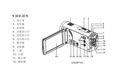
1 相机部件1:2:变焦键3:拍照键4:录像指示灯5:拍照指示灯6:7:8:录像键9:上键10:右键11:确认键12:删除键模式键1516D828FHD13:下键15:菜单键16:smart键17:18:回放键19:USB接口20:HDMI接口21:TV接口22:液晶屏D868FHD2324252623:闪光灯24:麦克风25:镜头26:镜头盖开关27:电池盖28:三脚架孔27282 按键功能介绍1)变焦键:向左(W)画面缩小,向右(T)画面放大。
2)拍照键:拍照模式按此键进行拍照。
3)录像键:录像模式按此键进行录像。
4)模式键:用于切换录像模式与拍照模式。
5)删除键:快捷删除当前模式的最后一个文件。
6)菜单键:按菜单键,进入菜单设置界面。
7)Smart键:按Smart键,进入灵智模式。
8)回放键:按回放键,进入浏览视频文件或照片文件界面。
9)上键:在拍照模式,按上键设置强制闪光、自动闪光、禁止闪光。
长按上键3秒钟进入爱婴模式,禁止闪光。
再次长按上键3秒钟退出爱婴模式。
(备注:【 】表示强制闪光,【 】表示自动闪光,【 】表示禁止闪光。
)10)下键:在拍照模式,按下键设置自动对焦和微距拍摄。
(备注:【 】表示自动对焦,【 】表示微距拍摄。
)11)左键:在拍照模式,按左键设置连拍和延迟拍摄。
(备注:【 】表示三张连拍,【 】表示延迟10秒拍摄。
)12)右键:在拍照模式,按右键进入趣味拍照设置。
13)确认键:确定选择设置。
14)电源键:打开/关闭电源。
3 安装电池1 :打开电池盖。
2 : 将锂电池装入电池槽,注意电池安装方向。
3 : 装好电池后,关闭电池盖。
4 电池充电1 :请将摄像机处于关机状态,用附带的电源适配器线或者USB线连接摄像机。
2 :连接成功后充电指示灯亮红色,开始充电。
3 :充电完成时,充电指示灯变为绿色。
备注:第一次使用该充电电池时,请至少对该电池充电 8 小时上。
5插入存储卡1 :数码摄像机处于关机状。
TCL868说明书

pci08/pci16用户操作手册(for windows 2000/xp)tcl 8.9.92010年05月01日目录第一章系统简述 ----------------------------------------------------------11.1基本功能 ------------------------------------------------------ 1 1.2性能特点------------------------------------------------------ 1 1.3录音方式1.4技术参数------------------------------------------------------11.5硬件配置------------------------------------------------------2------------------------------------------------------2第二章系统安装 ----------------------------------------------------------32.1系统配置 ------------------------------------------------------ 3 2.2语音卡硬件安装 ------------------------------------------------ 3 2.3语音卡驱动程序安装-------------------------------------------- 3 2.4录音系统软件安装----------------------------------------------4第三章录音系统使用说明--------------------------------------------------53.1系统主界面 ---------------------------------------------------- 5 3.2系统管理------------------------------------------------------11 3.2.1系统参数设置----------------------------------------------11 3.2.2 用户信息设置通道姓名设置----------------------------------------------13 3.2.3----------------------------------------------133.2.4通道参数设置 ----------------------------------------------143.2.5数据库管理 ------------------------------------------------213.2.6操作日志管理 ----------------------------------------------213.2.7关闭录音系统 ----------------------------------------------223.3录音管理 --------------------------------------------------------223.3.1查询录音 --------------------------------------------------233.3.2备份录音文件 ----------------------------------------------243.3.3查询留言 --------------------------------------------------253.3.4播放语音文件 ----------------------------------------------263.3.5转换语音文件格式------------------------------------------263.3.6查询未接来电 ----------------------------------------------273.3.7设置过滤电话信息------------------------------------------283.3.8查询过滤电话呼叫------------------------------------------283.3.9统计呼入呼出通话量---------------------------------------- 293.4操作员管理 ------------------------------------------------------293.4.1修改操作员密码 --------------------------------------------303.4.2增加删除操作员 --------------------------------------------303.5客户资料管理 ----------------------------------------------------313.5.1客户资料管理 ----------------------------------------------323.5.2客户沟通记录 ----------------------------------------------323.6交换机管理 ------------------------------------------------------333.6.1私有交换机参数设置 ----------------------------------------333.6.2显示交换机的原始话单数据 ----------------------------------343.6.3显示交换机外线名称设置 ------------------------------------35第四章远端电话查询、远端电话监听、呼入报号、留言功能介绍 -----------------364.1远端电话查询 ----------------------------------------------------36 4.2远端电话监听 ----------------------------------------------------36 4.3呼入报号留言功能功能 ----------------------------------------------------36 4.4--------------------------------------------------------36第五章网络录音留言管理和客户信息管理--------------------------------------375.1登陆录音系统服务器 -----------------------------------------------37 5.2录音管理---------------------------------------------------------375.2.1、网络录音查询和留言查询 -----------------------------------375.2.2、网络留言查询 ---------------------------------------------385.2.3、网络监听 -------------------------------------------------395.3客户信息管理 ----------------------------------------------------405.3.1、客户资料管理 ---------------------------------------------405.3.2、客户沟通记录 ---------------------------------------------405.3.3、弹出客户信息 ---------------------------------------------41第一章简述tcl数字录音系统是我公司根据通信、电力、厂矿、公安、企业、学校、煤矿、个人办公、公司、酒店、证券等行业及其它领域的要求,并结合其应用特点,自主研制并开发的全数字化录音设备。
AT868超声波流量计原理与操作Wetted

tup = Ultrasound is Decelerated by Flow tdn = Ultrasound is Accelerated by Flow
tup tdn t tup tdn V f( t) Q V A
焊接短管
1.测量管线直径 2.确定中心线和传感器的轴向距离(外径) 3.标出短管焊接位置 4.确定第一个短管的焊接位置,做水平线,验 证第二个焊接位置与第一个焊接位置对 称,如有误差进行调整,上下半周长一定要 相等.
焊接短管.
焊接短管.
焊接短管.
焊接短管.
焊接短管.
5.开孔,并再次确认两孔对称 6.安装焊接专用工具,进行焊接. 7.焊接时应在两边先焊四个点,松开导杆固定锣丝. 确认导杆能前后移动.再固定锣丝,两边间隔焊 接,以防产生应力,导致导杆变形.焊接完成后要 确保导杆能轻松移出. 8.测量短管两端面的距离并记录. 9,检查短管的轴向距离是否与外径相等,并记录.
AT868超声波流量计原理 与安装调试
GE-SENSING:袁聪坚
How do we measure flow with it?
Transit-time Technique
Transducer is Both Transmitter and Receiver Encoded Ultrasonic Pulses Transit Times
其中:c是超声波在非流动介质中的声速,V是流体介质的流动 速度,tu和td之间的差为:
式中X是两个换能器在管线方向上的间距。 为了简化,我们假设,流体的流速和超声波在介质中的速度相 比是个小量。即: 上式可简化为:
建伍TK868资料
看电流表6-7A就够了,想坏的快就调到255,如果机子没伤的话137就出25瓦以上了(不包括868H)第三项,信令平衡87.第四项调制频偏,63左右,第五项亚音调制频偏,220左右,第六项接收灵敏度127,看实际效果调制,第七项静噪抑制21看实际效果再调.好机器啊,刚改了一台到业余段,情况如下:调整菜单设置为450-3,随便插一根20厘米的电线做接收天线,手动置频到438.1,用手台微功率距离两三米发射,接收不到或断续、难以辨别语音。
按照网上说明,搭一个稳压电路提高VT电压到9.7V,其他条件不变再试,868在办公室内桌子上接收,手台微功率在走廊中发射,相距约30米左右能够稳定收到手台信号,语音难辨。
手台在868旁边发射,有啸叫,伴随很强的杂音,仍然难以辨别语音。
按SCN开机,450-3状态下:括号内为设置参数1.频率0-255(140)2.射频功率0-255(150)3点调整2L低0-255(150)低端点2C中0-255(150)中心点2H高0-255(150)高端点3.信令平衡0-255(100)4.最大调制频偏0-255(120 )3点调整4L低0-255(55)低端点4C中0-255(120)中心点4H高0-255(200)高端点5.亚音频调制频偏0-255(170)6.接收灵敏度0-255(250)6L低0-255(250)6C中0-255(250)6H高0-255(250)7.静噪0-42 (8)采用上述设置,868机内四个貌似中周全部旋到高点,天线接口上插一根8厘米的电线当接收天线,使用G71A微功率档卸掉天线发射,频率438.500,拉开距离大约5-6米,868可以收到信号,有背景噪音,再远收不到。
调整868软件设置后接收业余段信号音质差的问题自然解决,现在音质很好。
改天找个帮手拉距离细调一下。
按主机器的两个向上箭头打开电源,那么就进入了vfo频率显示状态,还可以频率扫描按住MON 键调节频道上下键可以改变频率按住SCN 可以扫描按住 A 可以改变步进 5 6.25在这里简单说一下对此机的看法:个人观点谨供参考(^_^各位请不要抛砖头给我噢!)此机为KENWOOD 的一代精品。
AUR°EL S.p.A 868 MHz SAW 传输模块用户手册说明书

TX AM 868/NPSAW transmitter module with external antenna for applications with OOK modulation and with a 868.35 MHz carrier .Pin-outTX AM 868/NP ModulePin out descriptionPin 2 DATA IN Input data. +5V Pin 3 NC Not connected.Pin 4-11 GNDConnected to GND. Internally connected to a single ground. Pin 13 Uscita RF 50 ohm antenna connection. Pin 15 +VVoltage supply (+5.0 V)TX AM 868/NP technical featuresDESCRIPTIONMIN. TIPICO MAX. U.M. Reception Frequency 868,25 868,35 868,45 MHz Voltage supply range4,50 5,00 5,50 Volts Current consumption – Tx mode (CW) 21 24 mA Stand by current consumption 0 mA E.R.P. Harmonic < 1GHz -54 -36 dBm E.R.P. Harmonic >1GHz -30 dBm I.F bandwidth5 KHz Effective Power measured directly on 50 ohms antenna pin 10 12 dBm Data_In, low logic level voltage 0 0,1 V Data_In, high logic level voltage 4,2 V Working temperature -20+85°C Dimensions36 x 9.5 x 3 mm2 15Device usageIn order to take advantage of the performances described in the technical features and to comply with the operating conditions which characterize the certification, the receiver has to be fitted up on a printed circuit, considering what follows:Voltage supply:1. The transmitter must be supplied by very low voltage security source protected against short circuits.2. Maximum voltage variation admitted: ± 0.5 V.3. De-coupling, next to the transmitter, by means of a ceramic capacitor of minimum 100.000 pF value.Ground:It must surround in the better way the welding area of the receiver. The circuit must be achieved in double layer, with throughout vias to the ground planes, approximately each 15 mm. It must be properly dimensioned inthe antenna connection area, in case a radiant whip antenna is fitted in(and area of approximately 50 mm is suggested).Picture 2: Lay-out advised for a correct working of the receiver50 Ohm Line:1. It must be as shorter as possible.2. 1,8 mm wide for 1 mm thick FR4 printed circuits and 2,9 mm wide for 1,6 mm thick FR4 printed circuits. On the same side it must be kept 2mm away from the ground.3. On the opposite side a ground circuit area must be present.Antenna connections:It may be utilized as the direct connection point for the radiating whip antenna.It can bear the connection of the central wire of a 50 ohm coaxial cable. Be sure that the braid is welded to the ground in a close point.1. A whip antenna, 80 mm long and approximately 1 mm dia, brass or copper wire made, must be connected to the RF input of the receiver.2. The antenna body must be kept straight as much as possible and must be free from other circuits or metal parts (5cm minimum suggested distance).3.It can be utilized both vertically or horizontally (the previous is highly suggested), providing that connection point between antenna and receiver input is surrounded by a good ground plane.N.B: As an alternative to the above mentioned antenna it is possible to use the whip model manufactured by Aurel (see related Datasheet and Application Notes).By fitting whips too different from the described ones, the EEC Certification is not assured.Technical Suggestions1. Keep the transmitter separates from all other components of the circuit (more than 5mm).2. Keep particularly far away and shielded all microprocessors and their clock circuits.3. Do not fit components around the 50 Ohm line. At least keep them at 5 mm distance.4. If the antenna connection is directly used for a radiating whip connection, keep at least a 5 cm radius free area. In case of coaxial cable connection, 5 mm radius will suffice.REFERENCE NORMATIVEThe TX AM 868/NP transmitter is approved by CE and in particular satisfies the European normative EN 300-220 and EN 301-489 with 5,0V voltage supply. The product was tested in according with EN 60950 normative and it’s usable fitted in an isolated housing to ensure the above normative. The transmitter must be supplied by very low voltage security source against the short circuits. Usage of transmitter module is foreseen fitted in the housing which ensure the agreement of EN 61000 normative is not directly applicable to the module itself. In particular, it’s at the user’s care the isolating of the extern antenna connection and antenna too, in fact the RF output of the transmitter is not able to directly bear electrostatic charges foreseen in the above normative.CEPT 70-03 RecommendationIn order to comply with such normative, the device must be used on the time scale with maximum duty cycle time of 1% on an hourly basis.。
TK-808(868) 的设置与实用功能开发
TK-808(868)的设置与实用功能开发TK-808系列是KENWOOD公司出品的专业车载电台,可存储16个频道,具有体积小巧、操作简单、坚固耐用的特点。
该系列产品有TK-808(25W)和TK-808H(35W)两大类,后缀带有字母“H”的型号具有高功率35W输出。
作为专业电台TK-808按照指标保证频段分为高段机M(450-470MHz)和低段机M4(400-420MHz),但通过简单的调试都可以很好的工作在430-440MHz业余波段中。
KENWOOD TK-808属于专业电台,所以要求在使用前由专业人员为用户设置好通讯频率,使用户操作尽量简单,减少误触动可能带来的影响通讯的可能。
对于业余无线电爱好者来说这样一来留给用户面板操作功能就比较少,在使用前必须预先设置,接下来就先简要介绍TK-808系列的设置。
该机为了防止用户误动对于编程和菜单设置功能可以通过机内跳线加以限制。
打开机盖机内靠前面板侧有一组CN7跳线,短接左侧两个端子(SET侧)为设置模式,短接右侧两个端子(USE侧)为用户模式,用户模式下禁止编程。
如果要将TK-808送交国家无委验机就必须处于用户模式。
实际上TK-808长期处于设置模式下也不影响性能,反而给业余无线电爱好者设置频率带来方便,无需频繁的打开机盖。
TK-808频率的设置在设置模式下按住前面板上“CALL”键开机就可以看到一频道的接收频率,如果没有看到具体频率依然显示ch符号则检查机器是否处于设置模式。
Tk-808的频率设置依次是设置接收频率è设置接收亚音编码(如果安装TSU-7组件)è设置发射频率(屏幕上显示发射的箭头)è设置发射亚音编码。
设置项目的确定是通过按PTT键确认。
在很多专业机中没有像业余机采用“差频”的概念而是采用收发频率分开设置,可以适用不同的应用场合。
TK-808在设置接收频率时通过按“SCAN”键在屏幕上可以出现或消除“ADD”的标记,该标记表示当前信道被列入扫描列表,也就是说如果某一信道没有“ADD”标记以后将不参与扫描。
AT供电变电所操作手册讲述
变电设备操作手册安技科编制2011-4-8目录目录 (2)一、开关 (4)1.1 220KV进线电动隔离开关的操作说明 (4)1.2220KV断路器操作说明 (6)1.327.5KV电动隔离开关操作说明 (7)1.427.5KV手动隔离开关操作说明 (8)1.5 27.5KV断路器操作说明 (9)1.6 27.5KV组合断路器操作说明 (10)1.7 27.5KV组合隔离开关操作说明 (11)1.8 27.5KV快速合闸隔离开关操作说明 (12)二、后台功能操作 (13)2.1测控系统的启动 (13)2.2历史事件查询 (13)2.3负荷曲线及数值查询 (14)2.4其他数据查询 (14)2.5 继电保护、重合闸、备自投的投退 (15)2.6 定值修改 (16)2.7 故障录波 (16)三、交、直流盘操作 (18)3.1倒回路 (18)四、远动通道通断检查 (19)五、设备巡视 (20)5.1巡视路线 (20)5.2主要设备巡视 (20)六、运行方式 (25)6.1正常运行方式 (25)七、抄表 (26)一、开关操作1.1 220KV进线电动隔离开关操作说明1.1.1后台操作对高压开关的控制(如:断路器、电动隔离开关)登录操作界面,选择相应的操作权限,在主接线图界面,右键单击图上开关受控单元,左键选择“遥控分”或“遥控合”进行后台控分合操作。
注:后台操作高压开关的程序相同。
1.1.2测控盘上操作1、转换开关:远方、当地2、分、合闸按钮:“红色”合闸按钮、“绿色”分闸按钮3、正常状态转换开关在“远方”位4、当地电动操作:①、将转换开关打至“当地”位;②、按“红色”按钮为合闸,按“绿色”按钮为分闸;③、操作完成后,将转换开关打至“远方”位。
1.1.3本体操作1、转换开关:LOCAC(近控)、STOP(停)、REMOTE(远方)2、分、合闸按钮:CLOSING(红色)合闸按钮、OPENING(绿色)分闸按钮3、正常状态转换开关在REMOTE(远方)位4、当地电动操作:①、将转换开关打至LOCAC(近控)位;②、按红色按钮(CLOSING)为合闸,按绿色按钮(OPENING)为分闸;③、操作完成后,将转换开关打至REMOTE(远方)位。
JS868快速操作指引V1.5

主菜单|—时钟管理| |—设置时间 | |—误差校准| | |—无需调整 | | |—每天调快 | | |—每天调慢 | |—报闹时间| | |—闹铃01->| | | |—开启闹铃 | | | |—报闹时间 | | | |—持续时间| | | |—闹铃星期—星期日、星期一…星期六 | | | 。
| | |—闹铃16(同上) |—卡片管理| |—增加卡片 | |—修改卡片 | |—删除卡片 |—系统设置| |—设备类型—两门双向、四门单向| |—3设备机号 {4网络设置—本机地址、子网掩码、默认网关、通讯密码} | |—背光模式—关闭、常开、自动、时区 | |—发音提示—键盘音、闹铃音、提示音| |—3通讯速率—2400bps 、4800bps 、9600bps 、19200bps| |—记录选项—进门记录、出门记录、事件记录、记满循环、 | | 禁止相同、容量预警,5位卡号 | |—菜单密码 | |—资源统计 | |—清除系统 | |—屏幕灰度| |—防撬开关—开启防撬、关闭防撬 |—门禁管理 | |—设置门1| | |—权限设置| | | |—时段表—(时段0——时段31) | | | |—时区表—(时区0——时区63) | | | |—节假日| | | |—应用群组—(应用群组0——应用群组15)| | |—2管制类型—进出双管、进入单管、进管出任、潜回互锁 | | |—进入方式—只需刷卡、只需密码 | | | 卡加密码 —开启群组、关闭群组| | |—2门磁类型—门磁常开、门磁常闭、火警常开、火警常闭、无效 | | |—开门按钮—常开、常闭、无效| | |—开门时间 *注:设为254秒,开门将变为继电器触发方式 | | |—关门时间| | |—首入常开—开启首开、关闭首开 | | |—胁迫密码 | | |—开门密码| | |—密码群组— 开启群组、关闭群组 | |—设置门2(同上面 设置门1) | |—1设置门3(同上面 设置门1) | |—1设置门4(同上面 设置门1) |—端口设置| |—继电器1—门锁1、门锁2、电铃、报警、非法卡、无效 | |—继电器2—门锁1、门锁2、电铃、报警、非法卡、无效| |—WG 接口1—进门1、出门1、进门2、出门2、W26输出、W34输出、W44输出、无效 | |—WG 接口2—进门1、出门1、进门2、出门2、W26输出、W34输出、W44输出、无效 | |—本机读卡—进门1、出门1、进门2、出门2、无效 |—菜单语言—简体中文、English1为 设备类型 设为 两门双向 所不支持的功能2为 设备类型 设为 四门单向 所不支持的功能 3为 通讯方式 为RS485所独有支持的功能 4为 通讯方式 为TCP/IP 所独有支持的功能JS868使用快速索引功能简介:JS868 “蝙蝠侠”集考勤机、密码门禁、单体门禁、汉显读头和2/4门门禁控制器于一体;可完全兼容JS168“小精灵”。
振通 ZT-868 A 嵌入式无线数传电台 使用说明书

ZT-868/A嵌入式无线数传电台使用说明深圳市振通科技有限公司电话: (755)29994346、29994392传真: (755)29994384 邮政编码:518101地址: 深圳市宝安三区龙井路1号东江豪苑20F/C2;E-mail:*************深圳市振通科技有限公司是专门从事无线通讯产品开发的高科技公司,研制生产的ZT系列模块式无线数传模块采用先进的频率合成技术,CPU锁相环控制,配合调制解调器,可提供语音或数据信号的透明传输,能适应各种点对点、点对多点的无线数据通信方式,具有收发一体、安装方便、使用简单、性价比高、稳定可靠等特点,广泛用于各种数据的远程采集、控制系统之中,是一般有线系统的更新换代产品。
特点:z传输速率:1200bps、2400bps、4800bpsz语音或数据兼容的透明信号传输z频段范围150MHz、230MHz、350MHz、450MHzz可设置256个频点,每个频点间隔25KHZ(标准)z接收、发送一体,数字模拟信号皆可发送、切换迅速z空中收发频率既可同频,也可异频z双锁相环、双VCO结构、高稳定度z内部采用进口功放模块,发射功率可调(0.5~5W)z接口采用标准TTL、RS232(或485)电平,可以直连单片机或个人电脑 z可手动设置频率(内置频)或电脑写频z SMT工艺、不锈钢外壳、体积小巧、安装方便、可外接散热片z自带TNC天线接口,可直连天线发射z指标符合国家标准应用领域工业自动化控制、电力调度、水利工程施工、大型建筑工地、采油输油测控、油井水井计量、水情水文监测、气象资料传输、环保监测设备、地震监视网络、慢速图象传输、仓储货柜管理、商场超市理货、林业防护设施、城市公交营运,高速公路管理、调度控制、集群通讯、智能大厦、无线信标、江河航运、地质勘探、交通运输、移动定位、军事训练、公安报警、医疗监护、公用设施、自动抄表、遥控遥测、游戏娱乐及日常生活等各领域。
- 1、下载文档前请自行甄别文档内容的完整性,平台不提供额外的编辑、内容补充、找答案等附加服务。
- 2、"仅部分预览"的文档,不可在线预览部分如存在完整性等问题,可反馈申请退款(可完整预览的文档不适用该条件!)。
- 3、如文档侵犯您的权益,请联系客服反馈,我们会尽快为您处理(人工客服工作时间:9:00-18:30)。
GE PANAMETRICS
超音波流量計AT868
中文操作說明
巨路國際(股) 公司
LUMAX INTERNATIONAL CORT., LTD.
台北公司:台北市南港區園區街3之1號12樓
TEL : (02)2788-3656(代表號)
FAX : (02)2788-7369
AT868主機設定操作手冊
按 ESC ENTER ESC 進入PROGRAM。
PROGRAM CALIB RESET 按左右選擇PROGRAM按ENTER;下一選項有CH GLOBL。
※選擇CH進入下一選項 ACTIV SYSTEM PIPE I/O SETUP。
一、選擇ACTIV按ENTER進入,再選擇主機測量模式,一般選TRANS。
回※號
二、選擇SYSTEM 按ENTER進入(如單位設定為英制,請先進入GLOBL改成公制);
1. 設定CHANNEL LABEL及SITE/CHANNEL MESSAGE等名稱,確定後按ENTER。
2. 按左右選擇流量單位種類如L/S L/M L/H ML/D等,確定後按ENTER。
3. 按左右選擇流量數值小數點,確定後按ENTER。
4. 按左右選擇累積量單位種類如L ML M3等,確定後按ENTER。
5. 按左右選擇累積量數值小數點,確定後按ENTER。
回※號
三、選擇PIPE按ENTER進入,
1.選擇TRANSDUCER NUMBER按ENTER。
2.選擇PIPE MATERIAL種類,確定後按ENTER。
3.KEY IN PIPE OD,並選擇單位如mm m mm/PI m/PI,確定後按ENTER。
4. KEY IN PIPE WALL,確定後按ENTER。
5.設定有否LINING,確定後按ENTER。
6.設定TRACKING WINDOW(一般為OFF),確定後按ENTER。
7.設定FLUID TYPE,確定後按ENTER。
8.設定REYNOLDS CORRECTION(如FLUID TYPE是WATER就設ACTIV並選
擇STATC此時主機會自動顯示REYNOLDS CORRECTION),確定後按ENTER。
9.設定CALIBRATION FACTOR(一般不作修正,設為1),確定後按ENTER。
10.設定NUMBER OF TRA VERSES,按左右選擇1(Z)2(V) 3 4 5(一
般常設為2(V)),確定後按ENTER。
11.設定至此螢幕會顯TRANSDUCER SPACING;再依其數據調整夾具距離。
回※
號
四、選擇I/O按ENTER進入,設定ZERO CUTOFF(一般設0.0305m/s)。
回※號
五、選擇SETUP。
但選單內為原廠設定,非本公司工程師禁止作任何更改。
※※選擇GLOBL進入下一選項 SYSTEM I/O COMM。
一、選擇SYSTEM按ENTER進入,
1. 按左右選擇SYSTEM單位種類如ENG (英制) METRC(公制)等,確定後按ENTER。
回※※號
二、選擇I/O按ENTER進入,進入下一選項 ERROR OPTN LCD。
(一)選擇ERROR按ENTER進入,
1.設定ERROR HANDLING種類,HOLD (異常保持最後一筆資料輸出) HIGH (異
常保持20mA輸出) LOW (異常保持4mA輸出) HHIGH(異常保持大於20mA 輸出),確定後按ENTER。
回二項目
(二)選擇OPTN按ENTER進入,進入下一選項 A B C D。
1. A C 為4~20mA輸出,確定後按ENTER。
2.設定輸出種類,OFF 0~20m 4~20m,確定後按ENTER。
3.設定輸出種類,VEL VOLUM +TOTL -TOTL等,確定後按ENTER。
4. B D 為FREQ/TOTL輸出,確定後按ENTER。
回二項目
(三)選擇LCD按ENTER進入,進入下一選項OFF 1 2 3 4。
1.OFF (不顯示) 1 (顯示一種數據) 2 (顯示二種數據) 3 (顯示三種數據)
4(顯示四種數據),確定後按ENTER。
2.選擇顯示類別如VEL VOLUM +TOTL -TOTL DIAG(可設定主機內部
各項顯示值如信號強度、品質等等)等,確定後按ENTER。
回※※號
三、選擇COMM按ENTER進入,設定通訊協定,本主機設為9600,確定後按ENTER。
