DTH-100 干式恒温器(加热型)
DTG-RTD100系列数字电阻温度计说明书

New security feature uses magnetic stylus (included) for keypad activation. No accidental button presses. Perfect for dirty hands or if wearing glovesU L arge Multicolor Backlit Display with 25 mm (1") Digits Readable From Over 10.7 m (35')U U p to ±0.2°C (±0.3°F) or ±0.1% Rdg Accuracy U C onnects Directly to3-Wire Pt100 RTD Sensors U U ser Scaleable 4 to 20 mA , 0 to 5 or 0 to 10 Vdc Analog Output Standard U P owered by Internal Battery or External DC Power Supply U I ncluded Setup andService Software Allows for Fast Maintenance and Calibration via USB Connection U W ireless Transmitter Option Sends Readings to Remote Locations and Allows for PC-Based Chart Recording and Data Logging U L ow Power Operation and Sleep Mode for Long Battery Life U D isplay BacklightChanges from Green to Blue for Low Alarm and from Green to Red for High AlarmDigital RTD Thermometer316 SS Enclosure for Wash-Down and Marine ApplicationsDTG-RTD100 SeriesA v a i l ab l e w i t h B u i l t -I n W i r e l e s sT r a n s m i t t e r O pt i o nDTG-RTD100-1/4-600-E-W-ABwith angle bracket and wireless transmitter option,shown actual size.L a r g e 25 m m(1") D i g i t sAntenna connection for wireless option.A n g l e Br ac k e t O p t i o n f o rF l e x i b l e U s emonitoring, chart recording and data logging. A variety of user-configurable options and settings include: sample interval, units and backlight.reading at distances up to 10.7 m (35') easy. Models are available with or without integral standard sensors. Standard features include: internal battery external DC power supply operation, analog output and user programmable alarms. The wireless transmitter option allows for remoteOMEGA’s new DTG-RTD100 Thermometer Series features a rugged 316 SS enclosure that is designed specifically for wash-down and marine applications. The large backlit LCD display incorporates both large 25 mm (1") digits and a 25 segment bar graph that makeMagnetic stylus (included).NSpecificationsRange: -51 to 538°C (-60 to 1000°F) (depending on sensor selected)Accuracy: ±0.2°C (±0.3°F) or ±0.1% of readingResolution: 0.1°C (0.1°F)Operating Environment: -40 to 70°C (-40 to 158°F) 5 to 100% RH non-condensingRTD Probe/Sensor Input: Pt100, 3-wireDisplay Type: LCD with selectable backlightDisplay Digits: 4 digits, 9999 counts Character Height: 25.4 mm (1.0")Computer Interface: USB (one programming cable included)Sample/Display Interval: User adjustable from 0.375 to 30 seconds, preset to 1/secondPower: 3.6V lithium, 8.5 Ah capacity (“C” cell) included; 12 to 24 Vdc Battery Life (Typical): 1 year* Analog Output: User selectable0 to 5 Vdc, 0 to 10 Vdc, or 4 to 20 mA; Requires external 12 to 24 Vdc power supply for operationEnclosure: 316 stainless steel housing, ABS center gasketEnclosure Finish: Brushed 316 stainless steelEnclosure Rating: NEMA 4X (IP65)Settings (USB/Software)Units: °F, °C, KAlarms: User selectable “high” and “low” alarm limitsAnalog Output: User selectable scaling Backlight: On/off, or 10 second, 30 second, 1 minute, 5 minuteWireless Transmitter (Optional): Channel number, transmission rate, alarms, sensor offset, chart recording, data logging Dimensions:115.1 H* x 114.8 W x 74.2 mm D (4.53* x 4.52 x 2.92")(*height not including sensor)Weight: 0.72 kg (1.59 lb)Wireless Option SpecificationsTransmit Sample Rate:User programmable from 1 sample/ 2 minutes to 1 sample/every 2 seconds Radio Frequency (RF) Transceiver Carrier: ISM 2.4 GHzRF Output Power: 10 dBm (10 mW)Range of RF Link: O utdoor Line of Sight: Up to 120 m (400')Indoor/Urban: Up to 40 m (130') Software (Included Free): Requires Windows ® XP/Vista/7 (32- and 64-bit)Internal Battery: Two 3.6V lithium, 8.5 Ah capacity (“C” cell) included Data Transmitted to Host: Temperature reading, ambient temperature reading, RF transmit strength and battery levelReceive data from up to 48 transmitters, and provide a scalable retransmitted, hard wired analog output for 4 user selected transmitters in your system.UWTC-REC4 receiver UWTC-REC1Receive data from up to 48 transmitters, powered directly by the USB connection on yourcomputer.Wireless ReceiversTemperature Units (°C/°F)Large 25 mmReceiver/host with ethernet is compatible with UWTC and UWRTD connectors, transmitters and wireless probe assemblies. Connects directly toyour network or the Internet—no PC required!UWTC-REC2-D with analog output and display.design, Pt100 sensor with M12 male connector, stainless steel construction and 11⁄2" 16AMP cap, standard lengths from 3 to 6". Temperature range -50 to 200°C (-58 to 392°F).Probe sold separately.Probe sold separately.Probe sold separately.Temperature range -50 to 260°C (-58 to 500°F).heavy-duty design, Pt100 sensor with M12 male connector, stainless steel construction and 11⁄2" 16AMP cap, standard lengths from 3 to 6". Temperature range -50 to 200°C (-58 to 392°F).74-0574-05use with Remote SensorOptional Cables with M12C Connectors forRemote Sensor ConnectionDTG-RTD100-M12-M shown smaller thanactual size.General purpose M12 style cable with stripped leads and additional mating M12 field installable connector included.M12C-PVC-4-S-M-S-F-2, with Rugged PVC jacketed cables for wash-down Female model (-F) recommended forwashdown applications.O p t i o n a l W a l lM o u n t i n g B r a c k e tA v a i l a b l e UWTC-REC122 )DTG-RTD100 shown with integral industrialprobe and angle bracket option.DTG-RTD100 shown with M12 probe, soldseparately.NMagnetic stylus (included).Integral sensor.DTG-RTD100-M12-F with PR-21B-3-100-A-1/4-0600-M12 sensor, sold separately, shownsmaller than actual size.Purchase the DTG-100 with a 1⁄8 or 1⁄4" diameter industrial sensor attached or use the DTG-RTD100-M12-Fconfiguration to affix any M12style probe.Standard 304 or 316 stainless steel models–260L SeriesUniversal Angle Bracket OptionAntenna connection for wireless option.Integral sensor.DTG-RTD100-1/4-600-E-W, sensor included, shown smaller than actual size.Digital RTD Thermometer as an Integral Sensor1⁄8" or 1⁄4" dia, industrial sensor, 316 stainless steel construction, and 1⁄2 x 1⁄2 NPT fitting, temperature range -51 to 538°C (-60 to 1000°F).Ordering Example:DTG-RTD100-1/4-400-E, comes complete with thermometer and 4" L integral sensor.* Specify probe length; “300” for 3", “400” for 4", “500” for 5", or “600” for 6".** Specify analog output signal: “V1” for 0 to 5 Vdc; “V2” for 0 to 10 Vdc, “TC” for Type K thermocouple, or “MA” for 4 to 20 mA signal.To order with angle bracket option, add suffix “-AB” to model number for additional cost.To order with wireless transmitter option, add suffix “-W” to model number for additional cost.Note: Units with the wireless option require a UWTC series receiver or transceiver to operate.Ordering Examples: DTG-RTD100-1/4-600-E-W-AB, RTD meter with integral Pt100, 6" long, 1⁄4" diameter industrial probe with angle bracket and wireless options, and UWTC-REC1, 48-channel USB receiver.DTG-RTD100-M12-M , RTD meter with male M12 connector.。
Sygonix 蒸汽器恒温器 HT100 用户手册说明书

User manualSYGONIXradiator thermostat HT100Art.-No. 1377979ControlsHeating TimeBatterieverbrauchVacation FunctionEconomy TemperatureOpen WindowFunctionkeylockAttentionPROG TEMP ZEITFENS RESADAP URLA INST OFFS VERSMODE time (minutes)1. Remove battery cover/Insert batteries2. Enter Date and Time3.a Mounting on the radiator without adapterValve - Radiator Thermostat HT1001.OKOKOKMountingNo adapter is required for the following valves:Heimeier, Junkers Landys+Gyr, MNG, Honeywell Braukmann, since these have threaddimensions of M30 x 1.5 mm. Adapters for Danfoss RAV (pin must be put on the valve tappet) Danfoss RA and Danfoss RAVL are enclosed.An adapter is required for the following valves:Herz M28 x 1,5 mm, Comap M28 x 1,5 mm, Vaillant 30,5 mm, Oventrop M30 x 1,0 mm, Meges M38 x 1,5 mm, Ondal M38 x 1,5 mm, Giacomini 22,6 mm, Rossweiner M33 x 2,0 mm, Markaryd M28 x 1,0 mm, Ista M32 x 1,0 mm, Vama M28 x 1,0 mm, Pettinaroli If E1appears in the display then the installation was not successful. Look at the Support Table.4. Adapt3.b Mounting on the radiator with adapter Valve – Adapter – Radiator Thermostat HT100Start ready.1.OKPull the battery cover, in the recess on the underside of the housing, upwards. Insert two batteries of type AA/Mignon with correct polarity (observe plus / + and minus / -, see imprint in the battery compartment). Pay attention to the correct position of the batteries to avoid contact interference. Close the battery compartment again. Due to the lower output voltage of batteries (batteries = 1.5V, rechargeable batteries = 1.2V) there may be a very short period of operation. We therefore recommend to use high quality alkaline batteries for a long and safe operation.• For safety and licensing (CE) reasons, unauthorized conversion and/or modification of the product is prohibited. NEVER disassemble it.• The product is not a toy, it does not belong in children‘s hands.• The product is only suitable for indoor use, it must not get damp or wet.• Do not carelessly leave packaging material lying around.• It could be a dangerous toy for children.• Be careful when using the product. Knocks, blows or even a fall from a low height can damage it.• Should you have any questions that are not answered in this manual, please contact us or another professional.• Keep batteries out of the reach of children. Do not let batteries lying around openly as there is the danger of them being swallowed by child-ren or pets. If swallowed, consult a doctor immediately!• Leaking or damaged batteries can cause burns on contact with skin, therefore use suitable protective gloves when handling them. Leaking battery fluids are chemically very aggressive. Objects or surfaces which come into contact with them, can sometimes be massively damaged. Keep batteries at a suitable location.• Batteries must not be shorted, disassemble or thrown into the fire. Risk of explosion!• Conventional non-rechargeable batteries cannot be recharged, Risk of explosion!• Do not mix batteries with different state (e.g., full and half-full batteries. Always replace the whole set of batteries.• When inserting the batteries pay attention to the correct polarity (Note: Plus / + and minus).OKdd:mmy y y yhh:mmRAV PinBold for AdapterBasic Operating ModesMANU mode: In the MANU Mode HT100 regulates to the set temperature by hand.AUTO Mode: HT100 changes in the AUTO Mode according to the set Time program between two temperatures.The heating and economy times can be specified via the adjustable time program.A maximum of 8 switch points (4 heating and 4 economy times) may be set per day.The Radiator Thermostat HT100 has the following factory settings:Heating time: Heating to comfort temperature(factory setting: 1. heating time at 07:00 clock - 21 ° C) Saving time: Reduction to economy temperature (factory setting: 1. saving time at 22:00 clock - 16 ° C)With the setting wheel a change in the room temperature is possible in the AUTO Mode at any time, this will remain until the next switching point. The process can be terminated prematurely by pressing the MENU button.Button: Main MenuButton: ConfirmationMENUOKButton: Timer functionMANU/AUTOModusHere any temperature for a selected time period can be set. Press button, set the time for which the timer program is to be overridden. Confirm with OK. Set the desired temperature. Confirm with OK. A manual temperature change is then in the given period not possible, the setting wheel is locked. By pressing the Menu button, the lock-up can be released.Setting HolidaysFirst set the date of the re-start of the regular heating time. (Set the end of the holiday)OKSetting OffsetkeylockTimer functionOK OK Room temperature adjustment. Here you have the possibility to set a temperature of (-5 / + 5 °). The temperature determined by the instrument may differ from the perceived temperature by the user.In this case, the temperature determined by the instrument must be adjusted.OKDeclaration of ConformityHereby, Conrad Electronic SE, Klaus-Conrad-Straße 1, D-92240 Hirschaudeclares, that this product is in compliance with the essential requirements and other relevant provisions of Directive 1999/5/EC. The Declaration ofConformity for this product can be found at GuaranteeFor damages caused by failure to observe this Instruction Manual, the warranty/guarantee is voided! For consequential damages we assume no liability! For material or personal dam-age caused by improper handling or failure to observe the safety information, we assume no liability! In such cases, the warranty/guarantee is voided!sygonix®distributed byConrad Electronic SE Klaus-Conrad-Str. 1D-92240 HirschauTechnical SpecificationsPower supply: 2 AA batteries / MignonFactory settings: Comfort temperature: 21 ° C Economy temperature: 16 ° C1. Heating time: Start 7:00 o’clock 1. Economy Time: Start 22:00 o’clock Switching points: 4 heating times, 4 economy timesFrost protection function: Yes, activation at temperature below +6 ° C Calcification protection: Yes, valve movement 1x per week Window function: YesModes: Automatic / ManualDimensions: 80 x 70 x 52 mm (W x H x D)HilfeMENU MENU ProblemCauseSolutionBatteries are lowChange batteriesnot getting warm.Valve does not open, after Summer heating pause- calcified?boilerTake off Radiator Thermostat HT100 Move by hand the valve tappets back and forth several times.Radiator is not cooling down.Valve does not close completely.Possibly the closing point of your your valve seat has moved.EAdapt again (see “Adaptation”)Repeatedly move valve tappets by hand - perhaps an adaptation is not possible because your valve may be calcified, or the seal does no longer fulfill its function.Thrust piece falls out.(This may also cause an E1 error!)Due to an endless threadthe thrust piece mounted on the bottom may fall out when the controller was not applied on the valve.Insert thrust piece. Adapt the device via the point, or by removing and re-inserting thebatteries. Now, the endless threat rotates and tightens the thrust piece firmly. Attach to the radiator and adapt again.E1-E3By pressing any button the fault indicatordisappears from the display and the adaptation restarts! E1No adaptation possible.Radiator Thermostat HT100 not mounted on radiators.s the device correctly mounted on the radiator?Mount Radiator Thermostat HT100. E2Valve lift too short or Battery power too weak.Open and close valve tappets by hand several times or install new batteries.E3No valve movement possible.Do valve tappets move freely?+Hold both buttons for several seconds. Activate key lock.T o deactivate, hold the two buttons pressed for several seconds.OKLEDThe LED lights up in each case during the heating-phase until the set temperature is reached.PROGMondaySet the beginning of the 1. Heating TimeSetting Individual ProgramSet the beginningof the 1. Economy TimeYou can optionally enter additional heating and economy periods. If you do not want to make any further settings, confirm the display …–– ––“with OK.OKOKOKOK MENUDAY1Day/Block Maintenance and CleaningMaintenance or repair may only be performed by a specialist or specialist workshop. There are no serviceable components for you inside the product, therefore, never open/disassemble it (except for the battery change as described in this manual). Never use aggressive cleaning agents, rubbing alcohol or other chemical solutions as they may cause damage to the housing or even impair its operational functions.From the date of implementation of European guidelines 2002/96/EC and 2006/66/EC, into national law, the following applies: Electric and electronicdevices and batteries may not be disposed of in household waste. The consumer is obliged to return electric and electronic devices and batteries to the public collection points established for them or to the point of sale. The particularsinstructions or packaging points to these provisions. You make an important contribution to the protection of the environment by reusing or recycling old equipment/batteries or making use of them in other ways.D1-5 Mo-Fr D1-6 Mo-Sa D1-7 Mo-SuThe process can be terminated prematurely by pressing the MENU button.。
TH100系列干湿球温湿度控制器用户操作快速指南
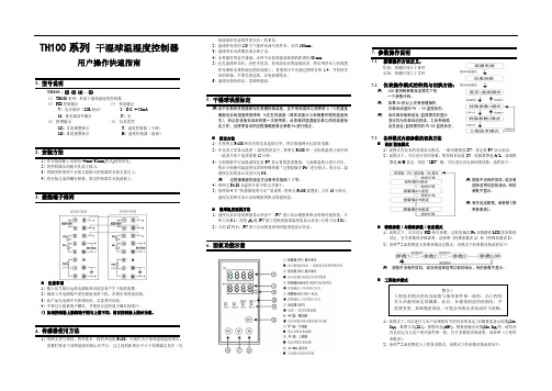
TH100系列干湿球温湿度控制器用户操作快速指南TH100 - ⑵⑶⑷- ⑸⑴TH100系列:单段干湿球温湿度控制器⑵PID控制输出⑶变送输出V:电压脉冲(SSR驱动)8:D.C. 4~20mAM:继电器常开触点N:无⑷报警输出⑸仪表类型M2:2组报警接点T:温度控制器(干球)M3:3组报警接点H:湿度控制器(湿球)2. 安装方法1)在安装面板上切割出44mm*92mm(竖式)的矩形孔;2)将控制器从面板开孔前方插入;3)将随货附的两个安装支架插入控制器的安装支架孔上;4)将安装支架的螺钉锁紧,固定控制器在安装面板上。
3. 接线端子排列⏹注意事项1)输入信号线应远离电源线和其他容易产生干扰的装置。
2)确保工作电源线不受电器装备的干扰。
否则应采用滤波器。
3)此产品无电源开关和保险丝,若需要可加装。
4)不要过分旋紧端子螺钉,并使用合适的端子螺丝接线片。
5)如果控制器上接线端子图与上图不同,请以控制器上图示为准。
4. 传感器使用方法1)用两支型号相同、特性基本一致的热电阻Pt100,分别作为干球和湿球温度探头,放置时要求干球和湿球的轴心应平行,且之间的距离应不小于传感器总直径(包括湿球纱布套的厚度在内)的3倍。
2)湿球纱布采用120号气象纱布或专用纱布,长约100mm。
3)湿球用水为蒸馏水或去离子水。
4)水杯最好带盖并盛满,水杯中水面到湿球底部的距离约30 mm。
5)包扎湿球纱布时,应把手洗净,再用清洁水将湿球洗净,然后用纱布上的线把纱布服帖无皱折地包围在湿球上,重叠部分不应超过圆周长的1/4,并剪掉多余的纱线,不要扎得过紧,以免影响吸水。
6)湿球应保持清洁、柔软和湿润。
5. 干湿球误差标定由于仪表和传感器都存在测量转换误差,且干球和湿球之间即使0.1℃的温度偏差也会给湿度转换带来1%左右的误差(具体误差大小和测量环境的温度有关),所以在设备安装后的第一次使用前,必须做好温湿度仪表之间的误差标定工作,且使用各自的过程值偏差修正参数Pb进行修正。
CTH100 温湿度记录仪说明书

'DWD $FTXLVLWLRQ
Communication Products and Converters, Data Acquisition and Analysis Software, Data Loggers Plug-in Cards, Signal Conditioners, USB, RS232, RS485, Ehernet and Parallel Port Data Acquisition Systems, Wireless Transmitters and Receivers
+HDWHUV
Band Heaters, Cartridge Heaters, Circulation Heaters, Comfort Heaters, Controllers, Meters and Switching Devices, Flexible Heaters, General Test and Measurement Instruments, Heater Hook-up Wire, Heating Cable Systems, Immersion Heaters, Process Air and Duct, Heaters, Radiant Heaters, Strip Heaters, Tubular Heaters
*(50$1< ZZZRPHJDGH 'HFNHQSIURQQ *HUPDQ\
%(1(/8; ZZZRPHJDQO
More than 100,000 Products Available!
7HPSHUDWXUH
Calibrators, Connectors, General Test and Measurement Instruments, Handheld Instruments for Temperature Measurement, Ice Point References, Indicating Labels, Crayons, Cements and Lacquers, Infrared Temperature Measurement Instruments, Recorders, Relative Humidity Measurement Instruments, PT100 Probes, PT100 Elements, Temperature & Process Meters, Timers and Counters, Temperature and Process Controllers and Power Switching Devices, Thermistor Elements, Probes and Assemblies, Thermocouples, Thermowells and Head and Well Assemblies, Transmitters, Thermocouple Wire, RTD Probes
CTHI-100B恒温恒湿箱
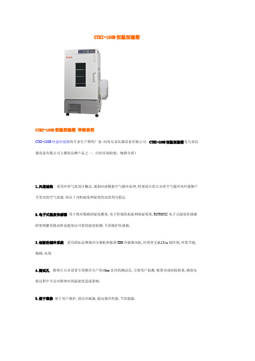
CTHI-100B恒温恒湿箱CTHI-100B恒温恒湿箱详细说明CTHI-100B恒温恒湿箱的专业生产销售厂家:河南兄弟仪器设备有限公司。
CTHI-100B恒温恒湿箱是兄弟仪器设备有限公司主推的品牌产品之一,历经市场检验,畅销全国!1.风道结构采用环形气流设计概念,强制对流模拟空气循环原理,特别设计的大功率空气循环风叶能够产生更高的空气流速.保证了内胆温度和湿度的高度均匀稳定.2.电子式湿度传感器用于绝对精确的湿度测量,电子控制的加湿和除湿系统,ROTRONIC电子式湿度传感器即使频繁更换试样也能保证可靠的湿度检测,不需维护传感器.3.创新的制冷系统采用国际品牌制冷压缩机和德国EBM冷凝器风机,环保型无氟134a制冷剂,环保节能,精确,高效.4.测试孔箱体左右各设置专用模具生产的45mm直径的测试孔,方便用户监测.配置内部硅胶软塞,确保实验过程中不会对箱体内的温湿度造成影响.5.便于维修便于用户维护,清洁冷凝器,提高制冷性能,节省能源.6.RS232接口PC机专用接口,专用软件光盘一张(适用简体中文WINDOWS2000或简体中文WINDOWS XP操作系统)通过PC机专用软件编制试验程序并监控和保存.通过PC机专用软件直接显示和打印试验数据.7.内胆积水方便维修内胆采用边高中低结构易排放,保证箱内清洁卫生.应用范围:主要用于药品的长期保存试验,食品质量试验,树脂材料,汽车零件,电器电子产品的环境试验,水体分析,BOD测定,细菌菌种,微生物培养,疫苗的保存等试验专用设备。
特点:◆本产品箱体采用进品数控机床,激光加工技术,外箱体采用优质的冷轧板,具有极强的防锈性,内胆采用SUS304不锈钢板。
◆箱底脚轮采用日本进口产品,方向自由可调,并可锁定,外箱体采用美国杜邦粉沫喷塑处理。
◆箱体左右各设置专用模具生产的45mm直径的观测孔,方便用户临测.内配硅胶软塞两只。
◆箱体保温材料采用德国拜尔无氟聚氨酯整体一次性发泡技术,极大提高了保温性能,从而大大降低能耗。
DMH系列干热灭菌柜验证方案

DMH系列干热灭菌柜验证方案编号:VP-SB-XZ-0106-01上海百正许昌药业有限公司1概述--------------------------------------------------- 1 2验证依据----------------------------------------------- 2 3验证流程_______________________________________________ 3 4验证小组人员及责任------------------------------------- 4 5验证实施的必备条件------------------------------------- 4 6设备技术参数一览表------------------------------------- 6 7安装确认----------------------------------------------- 6 8 运行确认 (10)9性能确认---------------------------------------------- 12 10验证结果综合评价------------------------------------- 18 11验证报告_____________________________________________ 18 12再验证_______________________________________________ 18目的:确认DMH系列干热灭菌柜的安装、运行、性能是否符合设计要求,是否符合生产及GMP要求。
同时确认该设备操作、维修、保养规程的可行性,并完善该设备操作、维修、保养规程。
范围:注射剂车间小容量普通线DMH系列干热灭菌柜(安装位置:器具洗)的验证。
责任人:质保室部长、生产技术部部长、设备动力部副部长、岗位操作人员、设备管理员、计量管理员、检验员、QA、档案管理员。
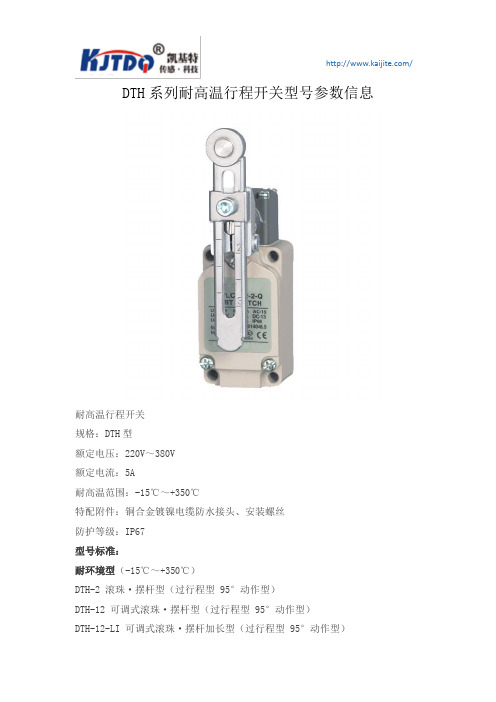
DTH系列耐高温行程开关型号参数信息
DTH系列耐高温行程开关型号参数信息
耐高温行程开关
规格:DTH型
额定电压:220V~380V
额定电流:5A
耐高温范围:-15℃~+350℃
特配附件:铜合金镀镍电缆防水接头、安装螺丝
防护等级:IP67
型号标准:
耐环境型(-15℃~+350℃)
DTH-2 滚珠·摆杆型(过行程型 95°动作型)
DTH-12 可调式滚珠·摆杆型(过行程型 95°动作型)
DTH-12-LI 可调式滚珠·摆杆加长型(过行程型 95°动作型)
DTH-L 可调式棒式·摆杆型(过行程型 95°动作型)DTH-NJ 高强盘簧型·万向式
DTH-NJ-2 高强盘簧树脂棒型·万向式
DTH-NJ-S2 高强盘簧型·万向式
DTH-NJ-30 高强盘簧型·万向式
DTH-D 顶部·柱塞型
DTH-D1 横向·顶部滚珠·柱塞型
DTH-D2 顶部滚珠·柱塞型
DTH-D3 顶部滚球式·柱塞型
DTH-D28 密封·顶部滚珠·柱塞型
DTH-SD 侧面·柱塞型
DTH-SD2 侧面滚珠·柱塞型
DTH-SD3 侧面球式·柱塞型
DTH-41 叉式·摆杆·锁定型。
瑞典达氏冷暖无叶风扇 DHF100说明书

Dustie Cool Heat Air Fan 瑞典达氏冷暖无叶风扇Please read this operating manual,Before using this product.注意事项如下区分,关于安全相关内容请阅读遵守。
安全注意事项警告:人有可能有大型事故或者重伤的内容注意:人可能受伤或者产生物质损伤的内容User Manual 说明书· 符合如下事项的人会导致伤害的可能性下,请勿使用商品。
残障人士,婴儿,儿童,老年人,药物服用者,饮酒者 及温度调整或者温度感知力比较差的人群· 扇叶严重晃动或者有异常噪音的时候,请中止使用商品并且咨询附近售后(扇叶的组装部位或者马达异常 等问题产品经常使用的话,会产生故障,发火,伤害的危险)· 产品使用的时候,请不要移动产品(会破损,伤害的危险)· 外出或者长时间不适用的话,请把电源线拔掉· 室外或者直射光线环境下不要使用产品· 如下场所请不要使用产品(浴室,桑拿,泳池等湿气比较重的地方,煤气罐 等热源近的地方,顾虑电器短路的地方,淋雨或者湿气高的地方· 长时间不使用的产品需要如下确认(通电源之后,扇叶不旋转,即使扇叶旋转,但是不规律的旋转模式,或者马达发热,旋转的时候,有异常噪音 等) · 破损的扇叶状态下请不要使用( 噪音或者扇片会导致伤害的危险)· 电源线破损的时候,为了不必要的危险,咨询售后或者代理点更换电源线· 扇叶旋转的时候,不要强制任意的旋转扇叶(有故障或者破损的原因)请采用本体的触摸键或者遥控器来使用商品操作使用说明产品开关首先产品放置在平坦和安全的地方,插入电源插座,开启产品后面的主开关。
然后发出低音,并且进入待机模式,状态显示目前温度。
模式选择【电源/暖风/送风】本体按【电源】键,弹出F2标识和送风2段运作。
按遥控器里【冷暖】键的时候,可以设定【暖风:H2->送风:F2】模式模式设定时候,该模式会显示状态灯(送风:绿色,暖风:红色)和装饰灯风量调整按产品的【风量】键或者遥控器的【风量 】按键可以调整风量,而且显示设定的风量状态左右/上下 摆头按产品的【左右摆头】和【上下摆头】或者遥控器上【左右摆头】和【上下摆头】调整设定,而且可以同时设定。
电热恒温鼓风干燥箱使用说明书
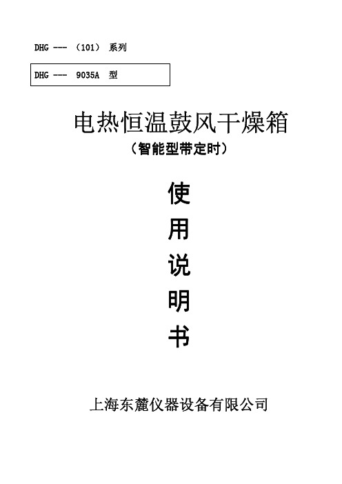
电热恒温鼓风干燥箱(智能型带定时)使用说明书上海东麓仪器设备有限公司目录一、示意图示意图 (2)2二、适用范围适用范围 (3)3三、技术指标技术指标 (3)3四、结构概述结构概述 (3)3五、操作步骤操作步骤 (4)4六、温度控制器操作说明温度控制器操作说明 (4)4七、注意事项注意事项 (7)7八、故障处理故障处理 (7)7九、装箱单装箱单 (8)8一、示意图:78911101、箱体2、铭牌3、控制面板4、门拉手5、搁板6、箱门7、温度控制器8、电源指示灯9、风门调节旋钮11、风机开关、风机开关10、电源开关10、电源开关11感谢您购买本公司仪器,在您启用鼓风干燥箱前,请仔细阅读使用说明书,相信它能使您感谢您购买本公司仪器,在您启用鼓风干燥箱前,请仔细阅读使用说明书,相信它能使您的的鼓风干燥箱发挥最大的功用。
阅读完本说明书后,请将其妥善保管,以便随时查阅。
二、适用范围:供厂矿企业、大专院校、科研及各类实验室等作物品干燥、烘焙、熔腊、灭菌之用。
三、技术指标:注:带“A ”为镜面不锈钢内胆,不带“A ”为镀锌板。
上表中技术参数的测试条件:环境温度2525℃℃、相对湿度不大于85%RH 85%RH、无试样负荷。
、无试样负荷。
测试工具:精度为0.10.1℃℃的标准水银温度计的标准水银温度计((水银头位于工作室内几何中水银头位于工作室内几何中心心)四、结构概述:DHG 系列台式鼓风干燥箱是系列产品,容积有30、50、70、140、240升五种规格。
干燥箱外壳体均采用优质钢板表面烘漆,工作室采用一般镀锌钢板或镜面不锈钢板,工作室内配有两层不锈钢丝制成的搁板,中间层充填超细玻璃棉型号9030(A)101-0(A)9070(A)101-1(A)9140(A)101-2(A)9240(A)101-3(A)电源电压AC220V 50Hz控温范围RT+10~250℃(最低控制温度为50℃)恒温波动度±1℃温度分辨率0.1℃额定功率870W 1570W 2070W 2470W 内胆尺寸(mm)345×325×325450×400×450550×450×550600×550×750外形尺寸(mm)625×510×490740×580×630830×650×730880×770×825型号9035A 9055A 9075A 9145A 9245A电源电压AC220V 50Hz控温范围RT+10~300℃(最低控制温度为50℃)恒温波动度±1℃温度分辨率0.1℃额定功率970W1220W1670W 2170W2570W内胆尺寸(mm)345×325×325425×400×345450×400×450550×450×550600×550×750外形尺寸(mm)625×510×490705×580×530740×580×630830×650×730880×770×825隔热。
1TZT-100 多功能恒温器使用说明书
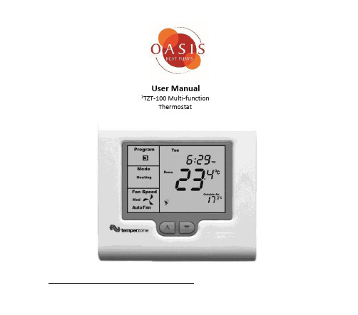
User Manual 1TZT-100 Multi-functionThermostatPlease take time to read and understand these instructions. Doing so will assist you to benefit from the many features offered in this premium product.If properly installed, your thermostat will provide years of trouble- free control of the air temperature within your living or working environment.The TZT-100 thermostat has been designed and built by Smart Temp Australia P/L, to be an attractive, highly reliable and an easy to use thermostat. The TZT-100 model is a modified version of a standard Smart Temp product. It has been configured specifically to Oasis Heat Pumps requirements for use on Oasis Heat and Chill Heat PumpsCare has been taken in the preparation of this manual. However, Oasis takes no responsibility for errors or omissions in this document. It is the responsibility of the user to ensure this thermostat and the equipment connected to it, is operating to theirspecifications, and in a safe manner.Due to ongoing product improvement Smart Temp Pty. Ltd., Oasis. reserve the right to change the specifications of this thermostat (or its components) without notice. . Any such changes may impact upon the operational detail described in this manual. The user should ensure they are reading documentation which relates to the version of thermostat they have..Table of ContentsIntroductionCommercial Programmable modeOn / Off and Mode SelectionSetting the ClockProgramming Your 2 Daily Events9After Hours Rn TimerManual modelOn / Off and Mode SelectionSetting the Fan FunctionSetting the ClockSetting Your Desired TemperatureSwitching Between Day and Night Set PointsTo Review the Set TemperatureCommon FunctionsThe Buttons Explained – ON/Off and Mode Selection etc Control ModesFan FunctionsThis TZT-100 thermostat is able to be used as a residential programmable thermostat, a commercial programmable thermostat or as a simple to use manual thermostat. Your installer will have set these modes to best suit your individual needs.For clarity, this user manual is broken into the following main sections.Commercial Programmable Mode.Allows programming of 1 “Start” and 1 “Stop” time and temperature per day.Manual Mode. (See page 18 of this manual).Use the MODE button to switch On and Off. No time-related programming available.Common Functions - All modes..Commercial Programmable ModeOn /Off and Mode SelectionTap the “MODE” button to cycle the thermostat throughthe available modes: “Heat” only, “Cool” only, Auto-changeover (Shown by both “Heat” & “Cool” in the LCD),Emergency Heat (if fitted), and “OFF”. If the fan mode isset to “Fan On”, when you select “OFF” mode the f anmode will automatically change to “Auto Fan” to preventthe fan from running unexpectedly while the unit is OFF.(Note – Not all modes may be active on your thermostat). Setting the ClockThe thermostat is fitted with a real time clock. This clock is used by the thermostat for the programming functions as described below.It is essential that the clock time and day are set accurately if you require your programmed events to start on time.To set the clock, tap the “PROG”button. The LCD will show the hours digit flashing. Use the up ()or down ()button to adjust the hours to the correct time(note the AM / PM symbol). Tap the “PROG”button again and now the minutes digits will flash.Adjust this value using the up ()or down ()button to show the correct minute. Tap the “PROG”button again and now the weekday flashes, again use the up ()or down () button to set this value to the correct day of the week. Tap the “PROG”button again to exit the clock set function.Programming Your 2 Daily EventsCommercial programming of the thermostat has been designed to be an extremely simple and logical process. The thermostat permits you to program a START time for the air conditioning system, then a Stop time for each day of the week. When the thermostat i s displaying “START” in the LCD, it will maintain whatever set point has been chosen. When the thermostat is displaying “STOP”in the LCD it will be OFF (or it will maintain an energyefficient overnight temperature if set by the installer).To enter the program mode:Press and hold the “PROG” button for 3 seconds. Thedisplay will change to show the Day “Monday” flashing.Using the up()or down()buttons adjust the dayto the day you wish to start programming an event or tothe day you wish to edit an existing event.Tap the “PROG” button to advance to the next step, TheLCD will show the word “START” with the hour’s digiting the up ()or down ()buttons adjustthe hours value to the time you wish the building AirConditioning system to start.Tap the “PROG” button again, now the minute’s digitsing the up ()or down ()b u t t o n s set theminute to the time you wish the building air conditioningsystem t o “START” for the currently selected day.Tap the “PROG” button to advance to the next step, The LCD will show the word “STOP”with the hour’s digit ing the up ()or down ()buttons adjust thehours to the time you wish the building air conditioningsystem to “STOP” for the currently selected day.Tap the “PROG”button again, now the minute’s digitsing the up ()or down ()b u t t o n s set theminute to the time you wish the building airconditioning system to “STOP” for the currentlyselected day. The LCD will now show the word “COPY”.You now have TWO optionsOption 1 - Continue programming as above.Simply continue to tap the “PROG” Button as you have been previously to advance to thenext day, “Tuesday” in this example “START” then “STOP” times, then Wednesday, Thursday etc, following the same simple steps previously explained….OROption 2 –“Copy” ProgramTo copy the values you have just set to other days of theweek tap the up()or down()buttons to“T A G”eachadditional day you wish to copy the currently set daysprogram to. When you have finished “Tagging” the daysyou desire press the “PROG”button to initiate the copyprocess. The word “Copy” will flash briefly to confirm thecopy process and your current days values will be copiedto the days selected. Normal programming will resume atthe next day to be programmed.Please Note –Your thermostat’s programs may be controlled from a Building Management System (BMS) thereby overriding any program you may have entered, as described ab ove. If the BMS is controlling the thermostat the word “Start” or“Stop” will flash in the LCD to indicate the thermostat program is under BMS control.After Hours Run TimerFor convenience, the installer may have set the after-hours run function. This function permits you to temporarily turn the thermostat back on for an installer pre-set period of time if the “Stop” program is running, at the conclusion of which the thermostat will automatically turn back off again.To activate the after-hours run timer, simply tap the“O/RIDE” button. (Or, the optional “After Hours” runbutton on the remote room temperature sensor.) The LCDwill show the word “Override” flashing in the LCD.You can cancel any unexpired portion of the timer periodby tapping the “O/RIDE” button again. The word“Override” will vanish from the screen.To Review the Set Temperature:Simply tap the up ()or down ()button to first turn the LCD backlight t h e n again to display the currently set temperature.Your Installer may have set a default “Start” event temperature that will be used at the commencement of each day; this will override any previous day’s temperature adjustments.Manual ModeON / OFF and Mode SelectionTap the “MODE” button to cycle through all the availablemodes: “Heat”-only, “Cool”-only, Auto-changeover (Both“Heat” & “Cool” show in the LCD at the same time),Emergency Heat (if fitted), and “OFF”. If the fan mode isset to “Fan On”, when you select “OFF” mode, the fanmode will automatically change to “Auto Fan” to preventthe fan from running unexpectedly while the unit is OFF.(Note – Not all modes may be active on your thermostat). Setting the Fan FunctionDetail of the thermostat’s fan control functions can be found on page 26 of this manual. Setting the ClockThe thermostat has a real time clock. In Manual mode, this clock has no function other than to display the time. The clock display can be disabled by the installer if desired.To set the clock, press and hold the “PROG”button for 3 seconds. The LCD will show the hours digit(s)e the up()or down()button to adjust t h e hours to the correct time (note the AM / PM symbol). Tap the “PROG” button and now the minutes digits will flash.Adjust this value using the up()or down()button to show the correct minute.Tap the“PROG”button and now the week day e the up ()or down () button to set this value to the correct day of the week.Tap the“PROG”button again to exit the clock set function or simply wait 30 seconds to auto exit this screen and return to the main operating display.Your clock is now set.Setting Your Desired TemperaturePress and hold the up ()or down ()buttons for3seconds.The t h e r m o st at display will change to show the word “SET”, and the active set point for the current mode. (Heating or Cooling)as you hold the up ()or down ()buttons the current set point will change accordingly.If Auto mode is selected (Indicated by both “Heat” & “Cool” showing on the display at the same time); after adjusting the “Heat” set point, wait without touching a button for 3 seconds. The thermostat display will change to show “Cool”, “SET” and your curr ent cooling set temperature.If desired change this value with the up ()or down () buttons.Wait for another3seconds for the thermostat to automatically exit this temperature setting screen. Your new set temperatures will be maintained.Switching Between Day and Night Set PointsIf the function is set by your installer, the thermostat will keep two sets of temperatures in its memory. Typically one set is for daytime set point temperatures, and the other for the night settings.The thermostat provides a quick and simple way to change between your day and night time set temperatures. Simply tap the “PROG” button. The display will change, showing “Day” or “Night” in the top left hand corner as you switch between modes.Set the “Day” set temperature(s), separately from the “Night”. Each are set as described on the previous page.To Review the Set Temperature:Simply tap the up ()or down ()button to first turn the LCD backlight t h e n again to display the currently set temperature.Common FunctionsThe Buttons Explained – ON/Off and Mode Selection etcMODETap this button to cycle the thermostat through the available modes: “Heat” only, “Cool” only, Auto-changeover (Indicated by the wo rds; “Heat” and “Cool” being visible on the display at the same time), Emergency Heat (if fitted), and “OFF”. When setting the thermostat to “OFF” mode, the fan mode will automatically change to “Auto Fan” mode so the fan does not unexpectedly continue to run.(Note – Not all modes may be active on your thermostat.)O/RIDE (Override)Commercial Programmable Mode:This button initiates the after-hours run timer. When activated, the thermostat will temporarily replace the “Stop” program temperatures with the “Start” program temperatures for an installer-defined pre set period.Residential Programmable Mode:The “O/RIDE” button is used to override the current “event” time scheduling, and to hold the currently set temperature indefinitely. This set temperature will be maintained until released by tapping the “O/RIDE” button again. “Hold” will be displayed in the LCD to confirm this function is active.(Up)Use this button to increase the desired room temperature for “Heating” or “Cooling” modes, or to increase a “value” in programming modes. Also used to force an override of the pre-programmed temperatures and temporarily replace them with a new higher set temperature.(Down)Use this button to decrease the desired room temperature for “Heating” or “Cooling” modes, or to decrease a “value” in programming modes. Also used to force an override of the pre-programmed temperatures and temporarily replace them with a new lower set temperature.PROG (Program)In Residential or Commercial Programmable mode:Tap the “PROG” button to begin setting the clock. Press and hold the “PROG” button for 3 seconds to begin programming your daily e vents.In Manual mode:Tap the “PROG” button to switch between “Day” & “Night” modes. P ress and hold the “PROG” button for 3 seconds to begin setting the clock.Control Modes:Heat-only Mode - The thermostat will turn on the Heating when the room temperature falls below the Heat set point temperature. In Heat-only mode the thermostat will NOT bring on the Cooling regardless of the room temperature and the Cooling set point temperature. In Heat-only mode, only the word “Heat” will be displayed in the LCD. When your thermostat is calling for heat, the word “Heating” will b e displayed.If the word “Heat” is flashing, the thermostat is performing an Anti-Rapid-Cycle safety delay prior to restarting the heating cycle.E. Heat Mode - The thermostat will only use your emergency heating device to maintain your desired heating temperature. This method of heating can be quite expensive therefore Emergency Heat mode is not recommended unless it is essential. When your air conditioning system is heating using emergency heat, the word “E.Heat” in the LCD will change to the word “E.Heating”.Cool-only Mode - The thermostat will turn on the Cooling when the water temperature rises above the Cool set point. In Cool-only mode the thermostat will NOT bring on the Heating regardless of the water temperature and Heating set point temperature. In Cool-only mode, only the word “Cool” will be displayed in the LCD. When your heat pump system is cooling, the word “Cooling” will be displayed.If the word “Cool” is flashing, the thermostat is performing an Anti-Rapid-Cycle safety delay prior to restarting the Cooling.Auto-changeover Mode - The thermostat will turn on the Heating if the water temperature falls below the Heat Set point temperature. Likewise it will commence Cooling if the water temperature rises above the Cool Set point. This is the recommended mode as it provides automatic control of the heat pump system to maintain the desired water temperature. Auto-changeover mode is indicated by both words “Heat” & “Cool” showing in the LCD at the same time.If “Heat” or “Cool” is fl ashing; the thermostat is performing an Anti-Rapid-Cycle safety delay prior to restarting the air conditioning system.Padlock Symbol.Whenever this symbol is shown, a control limit has been reached, or a button,or other function has been locked out.Spanner Symbol.If you see a spanner ICON flashing on your LCD, the installer has left yourthermostat in “Commissioning mode” Although your thermostat will operateyour heating and cooling system whilst in “commissioning mode”, all activesafety and energy conservations delays have been disabled. It is thereforeHIGHLY recommended that you contact your installer and request that theinstaller mode be disabled.Satellite SymbolThis indicates that your thermostat is receiving or sending information toanother “communicating” controller, or a Building Management System.Information received from the building supervisory control system maychange the function (mode or set temperature) of the thermostat. This isnormal and no cause for concern.The intent of this communications is to permit the centralised control of building functions which can include building climate control. To achieve this the BMS must be able to override thermostat settings made by the user. This ability is especially useful when a large facility has a number of heat pumps.TEXT “Locked”:The temperature of the outside air can initiate, or prevent certain functions within the thermostat from operating. If this happens, the word “LOCKED” appears. These functions automatically “unlock” once the outside air temperature becomes favourable. TEXT “FAULT”The TZT-100 has been “requested” to shut down the heating, cooling or heat pump system as a response from an external command. This request may have come from a sensor fitted to the heat pump system, a sensor monitoring supply power or a multitude of safety interlocks that can be used. To clear this fault a service call to your service person may be necessary.Remote Temperature Sensors:Your thermostat is fitted with an accurate and reliable temperature sensor used to measure the water temperature. There may be occasions where the thermostat cannot be placed in an ideal location for water temperature measurement; therefore the installer may have fitted “remote temperature sensor(s)”. These sensors will then report the water temperature from the remote temperature location back to the thermostat where this temperature will be displayed on the LCD.If your thermostat is used in a commercial location, your water temperature sensor may be fitted with a button which activates the “After Hours” run function. Consult your installer if you require this feature or have questions about its use.Symptom Suspected Fault Suggested remedyTemperature display seems inaccurate Sensor location needs to be checked Make sure sensor is in correct position Position of sensor in titanium pocket Make sure sensor is at the bottom of thetitanium pocketSensor calibration may be incorrect Call your installer, Smart Temp or Oasis, forinformation on how tocalibrate the air temperature sensorA remote temperature sensor may be in use. The temperature is NOT being measured atthe thermostat location. The remotelocation may have a different temperature.“Locked” appears on LCD. Heating or Cooling will not operate. This is not a fault.Outside air temp too high to permit heatingOutside air temp too low to permit cooling.Heating and/or cooling disabled to conserveenergy. The heating or cooling function canbe disabled when the outsidetemperature is warm or cool enough to notwarrant the use of the heat pumpController has no display Check main fuse Reset Circuit breakerCall an approved service agent. Faulty Wiring Call an approved service agent.Heat Pump System seems to run all the time Heating and/or cooling temperatures set to anun-achievable value.Set a lower heat temperature and/or ahigher cooling temperature. Review manualon setting temperaturesHeat-Cool System set to Heat Pump Mode Installer setting Incorrect – call for serviceSpanner Symbol in the LCD flashes all the time Installer has left the thermostat in“Commissioning mode”Contact your installer and request“Commissioning mode” be disabled.TroubleshootingSpecificationsInput Voltage 24VAC 50/60 Hz +/- 15%.Relay rating 24VAC @ 1Amp maximum per r elay.Operating Temperature 0-50°C (32 to 122°F).Operating RH 0-95% (non condensing).Storage Temperature 0-65°C (32 to 150°F).Size 113 x 103 x 23mm.Display Size 74 x 55mm.Temperature Sensor(s) 10K NTC type 3.Memory type Non volatile – Settings do not require battery backup. Accuracy +/- 0.3°C @ 25°C. (77°F)Stage Delays Minimum temperature change + time m ethod. Maximum stages controlled 2 cool & 3 heat (Installer s electable)Fan Speeds controlled 1 or 3 (Installer s electable)Timed upstage Delay 5~90 minutes (installer adjustable).Anti-Rapid Cycle Delay Installer selectable –“Off”, or“4-minutes”. Maximum hourly cycles Unlimited, 30, 10 or 6. (Installer s et)Display resolution 0.1 deg C (0.2F).Control Range Off to 45c (113F).Outside Air temp display range -8 ~ +60c (17 ~ 140F).Security Pin protected Installer menu with key l ock.Heat & Cool set control limits.Lithium backup battery for clock functions.Back light Blue EL.Backlight life 3,000 hours to half brightness.Optimised Start/Stop method Time-to-Start v Temp Differential method - updating. Communications Protocol Modbus RTU 4.8K 9.6K 19.2K No parity 1 data 1 stop.– Contact Oasis for Modbus objects l ist. “Auto Fan” speed selection method Difference between room and s et temp. Approvals FCC (Part 15) (pending), C-tick.Battery type CR 1220 (Backs up clock only)Battery life > 5years (10 years Maximum)Oasis Technologies LtdPh 09 5358891Mobile 021 725651Email:*********************************** © Oasis – All rights reserved.Intellectual Rights apply。
DHG-9070A型电热鼓风干燥箱说明书
DHG-9070A型电热鼓风干燥箱一、安全提示1、本产品必须可靠接地(切不可以零线或中线接地)。
2、在使用前请确认供电电源的电压、频率与产品要求符合。
3、产品使用独立的电源插座,并确认插头、插座接地良好。
4、不允许产品在运行中不关闭电源开关而任意拔掉或插上电源插头。
5、不允许随意接长或剪短产品电源连线。
6、不得放入易燃、易爆、易挥发及产生腐蚀性的物质进行干燥、烘焙。
7、不得触摸产品在80°C以上高温工作时的箱门、视察窗及周围表面,以防烫伤。
8、不得将手或物件插入进风口或出风口(槽)。
9、不得擅自进行修理,受本公司委托修理的必须由专业人员进行维修。
三、产品的使用1、使用前的准备产品应在下列使用条件中工作:1.1环境温度:5℃~40℃;相对湿度不大于85%;大气压力:(86~106)KPa;海拔高度不高于2000米;1.2周围无强烈震动源及强电磁场存在;1.3应放置在平稳、水平,无严重粉尘,无阳光直射,无腐蚀性气体存在的室内;1.4产品周围保留足够空间间隙,如右上图所示,不易放在火灾报警器下方;1.5产品供电电源电压见技术指标(附表一~表三);1.6合理放置,调整隔板位置及数量,放入工作物品,必须保持上下四周有一定空隙(>100mm), 重量以隔板不被压弯变形为宜。
2、开机通电①(PV)显示器(红)显示测量值根据仪表状态显示各类提示符。
②(SV)显示器(绿)显示设定值根据仪表状态显示各类参数值③指示灯AT灯(绿)与ATME灯公用,灯亮表示未使用定时器,即ST=0;闪烁表示在运行定时或ST=0状态下自整定HEAT加热输出灯(绿),工作输出时亮ALM偏差报警系统输出灯(红),工作时亮(注:本产品无COLD制冷功能)④SET功能键设定值修改参数符号的调出及参数修改的确认。
⑤移位键⑥⑦数字加、减键“↓”用于调整参数数值或进入自整定状态“↑”用于调整参数数值或观察定时运行时间2.1产品操作面板及控温仪面板布置;2.2关好箱门,把手应垂直向下;2.3根据物品的潮湿程度,调整风门至合适位置,“И”处开启角度最小,“Ξ”处开启角度最大(调节范围为60度角)。
DOH-1000型双扉电热气流烘箱再验证

文件类别:方案编号: DQH-1000型双扉电热气流烘箱验证方案目录1、目的 (3)2、范围 (3)3、人员及职责 (3)4、内容 (3)4.1设备概述 (3)4.2检查确认 (4)4.3运行确认(OQ) (5)4.4性能确认(PQ) (6)5、验证偏差处理 (8)6、验证周期 (8)记录 (9)验证结论及评价报告 (13)验证报告批准书 (14)1、目的检查DQH-1000型双扉电热气流烘箱性能参数与设计及工艺要求相符,确认该设备进风系统质量符合百级要求,满足无菌生产需要,并能稳定地保持所预定的功能。
用生物指示剂验证本设备灭菌能力达到工艺规定标准。
确认胶塞桶及工器具经本设备灭菌干燥后,质量符合标准。
2、范围本方案适用于本公司内DQH-1000型双扉电热气流烘箱的验证。
3、人员及职责3.1验证小组负责验证方案、报告的起草。
3.2设备维修人员负责设备的检查、测试及使用期间的定期维护,填写维护保养记录。
3.3生产车间负责设备操作,及记录的填写。
3.4质管部负责验证过程中的监督及检验工作。
3.5设备部经理或分线副总负责验证结果的评估。
3.6验证委员会主任负责方案、报告的批准。
3.7验证小组4.1设备概述DQH-1000型双扉电热气流烘箱安装于十万级区主要用于金属容器具的灭菌、除热原,要求设备内外表面、搁架表面光洁,用不锈钢制造,箱内空气经处理,洁净度达到100级。
设备基本情况:设备名称:百级净化热循环烘箱型号:DQH-1000设备编号:生产厂家:使用部门:。
安装地点:4.2检查确认目的:检查并确认设备技术参数性能符合设计要求。
4.2.1主要技术参数主要技术参数确认表确认人:日期:审核人:日期:4.2.2文件资料:检查设备档案的下列文件资料,归档是否齐全。
确认人:日期:审核人:日期:4.2.3检查并确定烘箱外观无损坏、无缺陷。
结果:烘箱外观无损坏、无缺陷(是□否□)。
确认人:日期:审核人:日期:4. 2. 4检查设备结构:本机应由箱体、电加热系统、热风循环净化系统、电控箱等组成。
海尔 HCB10-Q23XT12 立式热饮机清饮系列 使用说明书

4.2. 环保清单.......................................... 7
-1-
一、 品牌介绍
1.1. 品牌介绍
二、 产品介绍
2.1. 产品部件 2.1.1. 产品部件名称
2.1.2. 电气原理图
一、 品牌介绍
2.2. 技术数据 2.2.1. 技术数据 技术数据
产品型号 额定总功率 额定电压/频率
制热功率 额定制热水能力
制热水温度 使用环境温度 防触电保护类型 生产日期和编码 卫生许可批准文号
少间隔 1 米,底部不能垫泡沫、纸板等杂物,以免水分积聚导致漏电,机器 旁禁止放置易燃、易爆物品。
12、如果电源软线损坏,为避免危险,必须由制造商、其维修部或类似部门 专业人员更换。
本产品需在海尔授权的维修中心维修,在非授权的维修中心维修时,易引发 其他不安全因素。
3.2. 安装说明
3.2.1. 装箱单
4.2.1. 产品中限用物质的名称及含量........................ 7 4.2.2. 产品中与水接触材料列表............................ 7 4.3. 清洗保养.......................................... 8 4.3.1. 清洗保养.......................................... 8 4.4. 保修服务.......................................... 8 4.4.1. 用户须知.......................................... 8 4.4.2. 保修说明.......................................... 8 4.4.3. “1+5”成套服务................................... 9
Vitopend100 WH1B 中文样本
注重质量的同时,您是否在寻找一款兼优良性价比与上佳质量于一身的现代化燃气壁挂式锅炉?Vitopend 100 –W 是您的最佳选择。
各种不同的功率和规格,总有一款适合您。
整套菲斯曼供暖产品循环式燃气锅炉■适用于平衡式运行方式:10.5 - 24 kW两用壁挂燃气锅炉■适用于平衡式运行方式:10.5 - 24 kW和 13 - 30 kW符合低温标准2通过电子温度控制器保持高度的持续加热功率(30 千瓦制备每分钟 14 升)和高度出水温度恒定性。
生活热水高度舒适可靠、耐用 - 德国制造根据欧盟能源效率标准 92/42 的归类为低温供热锅炉。
节能、环保便于维修和维护带有多路插接系统的 AquaBloc 水路连接单元:可从前方直接接触所有需要维- 达到 EN 13203两星级14 升/分钟(30 kW)轻巧的机型和多路插接系统特别便于安装。
不需要侧面有维修间距。
安装简易该产品系列中最小且最静的供暖锅炉紧凑的外形和超低的运行噪音,适合安装于居室内。
725340 (24 kW)360 (30 kW)400 (24 kW)450 (30 kW)LED 状态和诊断显示–燃烧器运行显示 –电源显示 –故障指示灯电源和复位开关运行显示供暖锅炉待机燃烧器开供暖要求●●●●●调节 供暖水温度旋钮生活热水温度旋钮带有集成式诊断系统的控制器温度压力表直管接口(用于两用壁挂燃气锅炉)墙面安装支架弯管接口(用于两用壁挂燃气锅炉)Vitopend 100 –W 安装零件附件墙面安装支架1 安装模板的预安装2 锅炉安装4 启动6两用壁挂锅炉,适用于平衡式平衡式A 电源线连接区B 与下置式换热水箱配合使用,此外依据建议使用C 完工后地板表面循环泵剩余扬程(单位:h P a )流量(单位:l/h )A 剩余扬程 30 kWB 剩余扬程 24 kW型号 VICUPS–40/60订货号 7248 286安装方的防护格栅其它排烟/进气构件位于阿伦多夫的菲斯曼总部设有企业博物馆“ViaTemporis”利用环境热量、太阳能和再生能源系统。
力诺瑞特分体式太阳能热水器使用说明书
分体式热水中心使用说明书编制:日期:审核:日期:批准:日期:会签:日期:致消费者尊敬的用户:感谢您使用力诺瑞特公司的分体式太阳能热水中心。
在使用本产品前请仔细阅读本说明书,并请妥善保管以备查阅。
分体式太阳能热水中心的产品特点主要有:◆实现集热器与储热水箱的分离,集热器与建筑完美结合,能够解决漏水对建筑的威胁◆系统双循环承压运行,可多路供水◆辅助电加热器保证全天候、24小时供应热水◆系统实现全自动控制,具备防冻保护、过热保护、安全断开等功能,使用方便、安全可靠本说明书适用于力诺瑞特公司配置LPFT-C02型控制器的的家用分体式太阳能热水中心系列产品,规格型号如下:B-J-F-2-100/2.00/0.8-QB-J-F-2-150/3.00/0.8-QB-J-F-2-200/4.00/0.8-QB-J-F-2-300/5.00/0.8-QB-J-F-2-300/6.00/0.8-Q其他规格型号的家用分体式太阳能热水中心产品、定制产品可参考使用本说明书。
目录致消费者 (1)目录 (2)安全注意事项 (3)产品介绍 (4)一、产品结构 (4)二、部件功能介绍 (4)控制器使用说明 (5)一、主要技术参数 (5)二、按键介绍 (5)三、面板显示 (6)四、控制器主要功能 (6)五、操作说明 (7)六、接线图示 (10)使用注意事项 (11)系统主要部件技术参数 (12)系统热性能参数 (12)常见故障及处理 (13)维护与保养 (13)售后服务 (14)安全注意事项·在洗浴前应查看控制器显示面板上储热水箱上部温度(TT),以确定该水温是否适合洗浴。
警告:超过50℃的热水会引起烫伤。
为了您的家人尤其是儿童的安全,请在使用时特别小心!·不要试图开启太阳能站及储热水箱上的安全阀,有烫伤的危险!·带电工况下不要随意打开控制器的接线端盖,有触电的危险!·在用水时不要将水冲淋到控制器、插头及水箱电加热器处,否则会造成线路短路,危及人身安全和影响系统运行。
福建力得温控仪LDB系列说明书
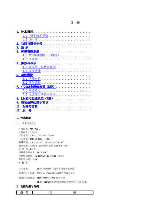
目录1.技术指标.......................................1.1 基本技术参数.............................1.2 标准.................................... 2.功能与型号分类................................. 3.显示.......................................... 4.传感电缆总成...................................4.1 D25传感电缆(三线制).....................4.2 传感器.................................... 5.操作与显示.....................................5.1 温控器工作状态显示........................5.2 按键功能..................................6. 功能模块.......................................6.1 功能密码..................................6.2 操作流程.................................. 7.4~20mA电流输出型(E型)........................7.1 功能特点..................................7.2 电流输出的技术要求........................ 8.RS485/232通讯型(F型)......................... 9.现场故障处理小常识............................. 10.配件与订货.................................... 11.服务........................................1.技术指标1.1 基本技术参数环境温度:-10~+55℃环境湿度:< 90%工作电压:220VAC (+10%,-15%)工作频率:50Hz或60Hz(±2Hz)测量范围:0.0~200.0℃或 -30.0~240.0℃测量精度:±1%FS(温控器0.5级,传感器0.5级)分辨力:0.1℃风机输出总容量:6A/250VAC控制输出容量:5A/250VAC;5A/30VDC (阻性)温控器功耗:≤8W1.2 标准生产标准: JB/T7631-2005《变压器用电子温控器》通过的认证标准:ISO9001:2000国际质量管理体系认证通过的试验标准:IEC61000-4:1995 国际标准GB/T17626-1998《电磁兼容试验和测量技术》标准2.功能与型号分类型号功能D型(常规型)三相巡回测量并显示/最大值测量并显示及两种功能相互切换;输入开路及故障自检显示并输出;冷却风机自动启停输出;超温报警显示并输出;超温跳闸显示并输出;风机手动控制/自动控制两种状态显示、输出及相互切换;各通道显示值数字补偿;“黑匣子”功能;风机定时启停控制功能;输出状态检测。
二甲醚
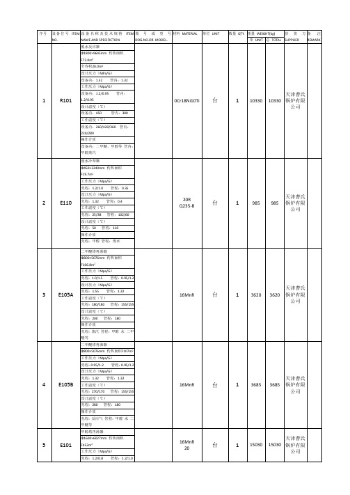
22
V103
甲醇收集罐
16MnR
台
1
天津曹氏
锅炉有限
公司
Φ1200×2420mm全容积2.3m3
工作压力:1.1/0.9Mpa
设计压力:1.21Mpa
工作温度:120/190℃
设计温度:220℃
操作介质:中采甲醇
23
二甲醚球罐
Q370R
台
2
117000
134000
盘锦兴达
石化设备
有限公司
序号
设备位号ITEM NO.
设备名称及技术规格ITEM NAME AND SPECIFICTION
图号或型号DOG.NO.OR. MODEL.
材料MATERIAL
单位UNIT
数量QTY.
重量WEIGHT(kg)
供货方SUPPLIER
备注REMARK
单UNIT
总TOTAL
1
R101
脱水反应器
0Cr18Ni10Ti
工作温度(℃)
塔顶:40塔釜:80冷却器壳程:25/30
设计温度(℃)
塔顶:100塔釜:100冷却器壳程:50
操作介质
塔釜塔顶:甲醇二甲醚氢等
冷却器壳程:冷却水
14
T101
甲醇塔
天津曹氏
锅炉有限
公司
Φ1300×29300mm全容积35.0m3
工作压力(Mpa/G)
塔顶塔釜:1.2/0.98冷却器壳程:0.5/0.3
工作压力:1.25Mpa
设计压力:1.38Mpa
工作温度:40/50℃
设计温度:60℃
操作介质:二甲醚
20
E102
换热器
海南万宁槟榔黄叶病毒病发生情况和症状分析
热带作物学报2021, 42(11): 3073 3078 Chinese Journal of Tropical Crops收稿日期 2021-07-20;修回日期 2021-11-11基金项目 海南省重大科技计划项目(No. zdkj201817);中国热带农业科学院基本科研业务费专项(No. 1630152017016);海南省院士创新平台资金。
作者简介 牛晓庆(1982—),女,博士,副研究员,研究方向:热带棕榈植物病害。
E-mail :**********************。
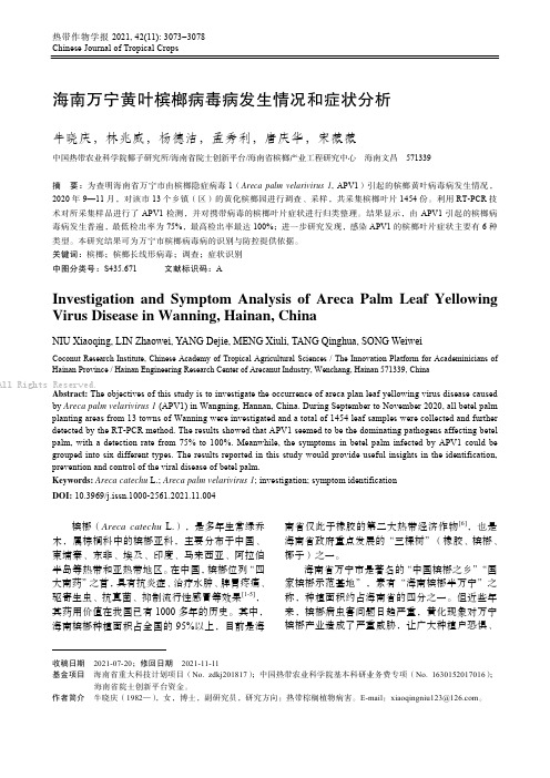
海南万宁黄叶槟榔病毒病发生情况和症状分析牛晓庆,林兆威,杨德洁,孟秀利,唐庆华,宋薇薇中国热带农业科学院椰子研究所/海南省院士创新平台/海南省槟榔产业工程研究中心 海南文昌 571339摘 要:为查明海南省万宁市由槟榔隐症病毒1(Areca palm velarivirus 1, APV1)引起的槟榔黄叶病毒病发生情况,2020年9—11月,对该市13个乡镇(区)的黄化槟榔园进行调查、采样,共采集槟榔叶片1454份。
利用RT-PCR 技术对所采集样品进行了APV1检测,并对携带病毒的槟榔叶片症状进行归类整理。
结果显示,由APV1引起的槟榔病毒病发生普遍,最低检出率为75%,最高检出率最达100%;进一步研究发现,感染APV1的槟榔叶片症状主要有6种类型。
本研究结果可为万宁市槟榔病毒病的识别与防控提供依据。
关键词:槟榔;槟榔长线形病毒;调查;症状识别 中图分类号:S435.671 文献标识码:AInvestigation and Symptom Analysis of Areca Palm Leaf Yellowing Virus Disease in Wanning, Hainan, ChinaNIU Xiaoqing, LIN Zhaowei, YANG Dejie, MENG Xiuli, TANG Qinghua, SONG WeiweiCoconut Research Institute, Chinese Academy of Tropical Agricultural Sciences / The Innovation Platform for Academinicians of Hainan Province / Hainan Engineering Research Center of Arecanut Industry, Wenchang, Hainan 571339, ChinaAbstract: The objectives of this study is to investigate the occurrence of areca plan leaf yellowing virus disease caused by Areca palm velarivirus 1 (APV1) in Wangning, Hannan, China. During September to November 2020, all betel palm planting areas from 13 towns of Wanning were investigated and a total of 1454 leaf samples were collected and further detected by the RT-PCR method. The results showed that APV1 seemed to be the dominating pathogens affecting betel palm, with a detection rate from 75% to 100%. Meanwhile, the symptoms in betel palm infected by APV1 could be grouped into six different types. The results reported in this study would provide useful insights in the identification, prevention and control of the viral disease of betel palm.Keywords: Areca catechu L.; Areca palm velarivirus 1; investigation; symptom identification DOI: 10.3969/j.issn.1000-2561.2021.11.004槟榔(Areca catechu L.),是多年生常绿乔木,属棕榈科中的槟榔亚科,主要分布于中国、柬埔寨、东非、埃及、印度、马来西亚、阿拉伯半岛等热带和亚热带地区。
- 1、下载文档前请自行甄别文档内容的完整性,平台不提供额外的编辑、内容补充、找答案等附加服务。
- 2、"仅部分预览"的文档,不可在线预览部分如存在完整性等问题,可反馈申请退款(可完整预览的文档不适用该条件!)。
- 3、如文档侵犯您的权益,请联系客服反馈,我们会尽快为您处理(人工客服工作时间:9:00-18:30)。
DTH-100 干式恒温器(加热型)
DTH-100 干式恒温器(加热型)是采用微电脑控制的恒温金属浴装置,以代替传统的水浴装置,可广泛应用于样品的保存和反应、DNA 扩增和电泳的预变性、血清凝固等。
DTH-100系列干式恒温器是一款满足外商需求、外观精美、性能卓越的新型恒温金属浴。
产品特点
1、蓝色液晶屏显示,界面清爽简洁,双节时间、温度设置,即时温度显示、时间递减显示。
2、仪器升温速度快、加热均匀、控温准确、稳定性高,低能耗无噪音。
3、内置温度偏差校准功能,自动故障检测及蜂鸣器报警功能。
4、内置超温保护装置,使用更安全可靠,延长机器使用寿命。
5、产品设计紧凑而严密,占用的空间范围小,带来更多的自由和方便。
6、多种模块选择,更换,便于清洁与消毒食用各种试管。
性能指标
DTH/DTH-100系列可更换模块。
