杭州瑞诚 金属浴 DH300-中文简介
金属浴介绍对比

金银杏金属浴 (红色为优势 红色为优势) 红色为优势
H2O3-100C 0-100ºC 8~30 ºC 1 ºC ±0.5 ºC ±0.5 ºC(0-85 ºC) ±1 ºC(85 ºC以上) 有 ≤13min (20℃至100℃)6 ºC/min H2O3-PRO 0-100ºC 8~30 ºC 0.1 ºC ±0.2 ºC
0.5 mL铝块
2 mL铝块
15 mL铝块
50 mL铝块
平板铝块
四、H2O3系列金属浴介绍
产品名称 冰浴 技术参数 控温范围 环境温度范围 温度显示精度 温度控制精度 温度均一性 升温速度* 0~2 ℃ 8~30 ℃ — ±1 ℃ ±0.5 ℃ — 16 ℃ 20~37 ℃ — ±0.5 ℃ ±0.5 ℃ — 连接仪 75C 0~75 ℃ 100C 0~100 ℃ 0~100 ℃ 8~30 ℃ 0.1 ℃ ±0.2 ℃ ±0.5 ℃ 8 ℃/min (16~60 ℃) 3 ℃/min (60~16 ℃) 1.5 ℃/min (25~4 ℃) 1 min~23 h 59 min 制冷/加热金属浴 程控金属浴
8~30 ℃ 1℃ ±0.5 ℃ ±0.5 ℃ 8 ℃/min (16~60 ℃) 3 ℃/min (60~16 ℃) 1.5 ℃/min (25~4 ℃) —
降温速度*
13 min (25~4 ℃) —
3 min (25~16 ℃) —
时间范围
四、 H2O3系列总体优势
• 独特性
– 可降温,且升降温速度快(最高可达8 ℃/min) – H2O3-96冰浴为独创产品,可替代制冰机和冰盒,保证实验 质量。 – H2O3-96L连接仪为特制产品,可替代笨重昂贵的制冷型水浴 锅的大部分功能; – H2O3-75C/100C为大范围控温产品,可替代水浴锅、制冷型 水浴锅、加热块、冰箱、培养箱等仪器的部分功能。 – H2O3-PRO为最新产品,可同时调控时间和温度,程序结束 后自动降至4 ℃保存样品 – 操作简便,防止样品污染
派克液压密封件说明书

派克汉尼汾公司版权所有未经许可不能摘录,翻印。
保留修改权利2021年6月警告销售条件本样本中产品和/或系统或相关产品出现故障,选型不当或使用不当,均可能导致人身伤亡和财产损失。
本文档以及由派克·汉尼汾公司及其子公司和授权经销商提供的其他资料,为具有技术知识的用户提供进一步研究所需的产品和/或系统选项。
重要的是,用户必须对您的应用进行全面的分析,并对当前产品样本中与产品或系统相关的资料进行评估。
由于工作条件以及产品或系统的多样性,用户必须自行分析和测试,并独自承担一切后果,包括:产品和系统的最终选型以及确保满足应用的所有性能、安全和警告等方面的要求。
派克·汉尼汾及其子公司可能会随时对本样本中的产品,包括但不限于:产品的特性、产品的规格、产品的结构、产品的有效性以及产品的价格作出变更而不另行通知.本样本中的所有产品均由派克·汉尼汾公司及其子公司和援权经销商销售。
与派克签订的任何销售合同均按照派克标准条件和销售条件中规定的条款执行(提供复印件备索)。
本公司的密封件,只能在本公司的文件资料述及的应用参数范围与接触介质、压力、温度和存放时间相一致的情况下才能使用。
在规定的应用参数范围外使用以及错误选用不同的材料都可能导致密封件寿命的缩短以及设备的损坏,甚至更严重的后果(如生命安全,环境污染等)。
样本中所列出的工作压力、温度范围、运动速度是极限值,它们之间相互关联、相互影响;在极端的工况下,建议不要同时把各个参数都同时用到极限值。
对于特殊的要求(压力、温度、速度、介质等),请联系派克汉尼汾公司以咨询合适的密封结构、材料、配置、安装建议等。
由于诸多工作参数会影响到流体传动系统及密封元件,这些设备的制造商必须在实际工作条件下测试、验证并批准密封系统的功能与可靠性。
此外,对于不断出现的新的介质(液压油、润滑脂、清洗剂等),用户特别注意它们与目前所用的密封件弹性体材料的兼容性。
我们建议用户在大批量应用之前,在厂内或现场先做密封材料的兼容性能测试,作为密封产品与系统供应商,我们建议用户遵循我们的这些建议。
金属浴介绍对比

H2O3-96L连 接仪
分子生物学实验 使用方便快捷,完全避免了人工 调节冰/水比例来达到16 ℃水浴的 16 ℃连接反应 不便和不稳定 与水浴制冷连接仪(circulator)相比 更方便、轻巧、廉价
二、H2O3系列金属浴介绍
产品型号 H2O3-75C 金属浴 H2O3-100C 金属浴 温度连续可调(0~75/100 ℃) 如果您不需要75 ℃以上的高 温,可选用H2O3-75C 特点 应用举例 冰上操作:0~4 ℃ 酶切反应:37 ℃ 逆转录:37~42 ℃ 蛋白酶K消化:37 ℃ 生物/化学发光反应:20~25 ℃ 凝胶回收:50~60 ℃ 连接反应:16 ℃ 保存卵母细胞:17 ℃ 感受态细胞制备培养:37 ℃,转化: 42 ℃ 核酸变性:70~85 ℃ 蛋白质变性:60 ℃以上 酶的冻融:4 ℃ 芯片、原位杂交:60 ℃ 试管内翻译/转录实验孵育:37 ℃、 70 ℃
8~30 ℃ 1℃ ±0.5 ℃ ±0.5 ℃ 8 ℃/min (16~60 ℃) 3 ℃/min (60~16 ℃) 1.5 ℃/min (25~4 ℃) —
降温速度*
13 min (25~4 ℃) —
3 min (25~16 ℃) —
时间范围
四、 H2O3系列总体优势
• 独特性
– 可降温,且升降温速度快(最高可达8 ℃/min) – H2O3-96冰浴为独创产品,可替代制冰机和冰盒,保证实验 质量。 – H2O3-96L连接仪为特制产品,可替代笨重昂贵的制冷型水浴 锅的大部分功能; – H2O3-75C/100C为大范围控温产品,可替代水浴锅、制冷型 水浴锅、加热块、冰箱、培养箱等仪器的部分功能。 – H2O3-PRO为最新产品,可同时调控时间和温度,程序结束 后自动降至4 ℃保存样品 – 操作简便,防止样品污染
gh300 数据手册说明书

3 电源管理和复位 ..................................................................................................................................................... 6 3.1 芯片上电时序................................................................................................................................................. 6 3.2 复位................................................................................................................................................................. 6
湿度(327k)

概述通常湿度的测量和记录都是采用人的毛发做为测量部件但是随着对传感器反应时间要求的提高以及湿度快速变化或者在25%的湿度条件以下-10温度测量条件的大量的出现极力推荐使用我们特别设计的的测量传感器PERNIX如果你希望订购PERNIX的设备请特别指明订购需额外价钱湿度计的显示表盘由镀铝材料制白底黑字PERNIX测量部件对我们的194~202和235E250无效194 订购号00.01940.100 000圆形湿度表适合与桌面和墙挂使用钩或钉住技术数据测量范围 5~100%RH, 2%的刻度精度 2.5%RH(定期校准)工作温度-60~70尺寸 102mm,35mm D重量 0.300Kg外表天蓝色暗色镀铬外壳198 订购号00.01980.100 000温湿度表由毛细管温度传感器组成的湿度指示器由于结合了这种功能你同时可以得到相对和绝对湿度也能得到温度和露点温度技术数据测量范围 5~100%RH-25~40尺寸 133mm,46mm D重量 0.500Kg精度 2.5%RH(定期校准)1K外表天蓝色暗灰色镀铬外壳201a 订购号00.02011.100 000这种湿度计可以作为多功能测量设备由测量以%为单位的相对湿度为单位的温度和以hPa为单位的饱和压力辅件用于仪器重新标订带泡沫入口的透明箔袋技术数据测量范围5~100%RH-30~50精度 2.5%RH(定期校准) 1.0K(<0),0.7K(>0)尺寸 81mm; 242mmH; 28mm D重量0.400Kg外表天蓝色暗灰色镀铬外壳201a 订购号00.02020.100 000 Lambrech Polymeter,这种温湿度表一体化仪表允许读出相对湿度绝对湿度温度露点温度饱和压力水蒸汽压力以及不饱和度PERNIX型号无效辅件技术数据测量范围5~100%RH0.1~80g/m³绝对湿度-30~50精度 2.5%RH(定期校准) 1.0K(<0),0.7K(>0)尺寸 81mm; 242mmH; 28mm D重量0.4Kg外表天蓝色暗灰色镀铬外壳204 订购号33.02020.008 000用于201a和202型号的单独配件湿度计重量 0.050Kg220F 50P 订购号00.02202.205 000杆型湿度计带PERNIX测量部件用于测量空气湿度和吸湿性材料的含水量绝对轻制金属制造带手柄防摔坏玻璃树脂视窗技术数据测量范围5~100%RH刻度2%RH精度 2.5%RH(定期校准)工作温度-60~70尺寸 118mm; 480mmL; 杆19X8mm重量0.600Kg外层天蓝色暗灰色金属杆末梢为黑色235E 250 订购号00.02350.125 000带支架的湿度计特别适合使用在不易到达的地方表面安装技术数据测量范围5~100%RH刻度2%RH精度 2.5%RH(定期校准)工作温度-60~70尺寸 120mm 法兰;共 280mm H重量0.400Kg外层天蓝色镀铬外环235 E125 订购号00.02350.112 500带支架的湿度计如同235E250,但是深度为125mm技术数据尺寸120mm 法兰;共155 mm H重量 0.300Kg空气湿度传感器800系列这些传感器被装配在我们的 PERNIX系列产品上既带本地显示也可用于在线测量电缆末梢带护套辅件1个回形针和一个六角罗冒 R 1”主要技术数据测量范围5~100%RH刻度1%RH精度 2.5%RH(定期校准)工作温度-60~70最大电流 60mA(~0.5W)尺寸共395 mm H(帽子105mm;80mmD)重量 1.500Kg外层天蓝色暗灰色镀铬外壳800 N 30 订购号00.08000.202.030技术参数电阻 50-30-50 Ohm,对数800 L0-100 订购号00.08000.201.010电阻 0-100 Ohm,线性800 MU 订购号00.08000.206 0?2 空气湿度传感器带电阻/电流转换器有两种不同的型号输出 0~20mA(0~100%RH) 订购号00.08000.206 0024~20mA(0~100%RH) 订购号00.08000.206 042详细技术数据电阻0-100 Ohm,线性工作温度范围 -30~70输出0(4)~20mA(0~100%RH),负载500 ohm工作电压24VDC,10%重量 1.600Kg空气温湿度传感器传感器 809被装备到PERNIX传感器和铂探头上现场湿度显示内置电子器件用于温湿度在线测量在设备顶部有电缆接头接头带护套(Pg16)主要技术数据湿度测量范围 5~100%RH精度 2.5%RH温度测量范围-60~70精度0.3K(0)其它工作温度范围-60~70最大电流60mA(电阻输出)10mA(温度输出)尺寸共395 mm H(帽子105mm;80mmD)重量 1.5Kg外壳天蓝色暗灰色镀铬外壳809 L100订购号00.08090.231 515详细技术参数电阻输出5-100-5 ohm,线性809L 0-100 订购号00.08090.231 010详细技术参数电阻0-100 ohm,线性809MU 订购号00.08090.266 0?2带2个R-I转换器2个不同的型号都有效输出 0~20mA(0~100%RH) 订购号00.08090.266 1024~20mA(0~100%RH) 订购号00.08090.266 142主要技术数据电阻 0-100 ohm,线性精度 2.5%RH温度0.3K工作温度范围-30~70输出0(4)~20mA(~0~100%RH和-30~40)最大负载500 ohm工作电压24VDC10%重量 1.7Kg电气传感器8091经济型订购号00.08091.000 000一体化温湿度传感器她的精巧和可靠的设计使得她同时适合使用在工业和气象应用技术数据湿度测量元器件电容测量范围 0~100%RH精度2%RH输出模拟信号0~1VDC阻抗>2000 ohm温度测量元器件 PT100测量范围-20~80精度0.1K输出0~1V其它工作温度范围-20~80工作电压10~30VDC,10%功耗大约0.8mA重量0.4Kg8092 订购号00.08092.130 402 精密的相对湿度和空气温度传感器可以高质量的使用在工业和气象场合7芯电缆对外连接湿度测量元器件电容测量范围 0~100%RH精度1%RH(5~95%RH)2%RH其它输出模拟信号0~1VDC阻抗>1000 ohm温度测量元器件 PT100测量范围-40~60精度0.3K输出 PT100其它工作电压10~30VDC,10%功耗最大2.5mA重量0.4Kg连接电缆适合传感器00.08092.130 420,包括插入式接头(母头)长度 3.3m辅件814 订购号00.08140.000 000传感器防护罩保护传感器不受日照和雨淋适合用于空气湿度传感器800和空气温湿度传感器809技术数据尺寸 170mmФ;440mmH安装方式直接安装到22mm的杆上重量 1.7Kg漆层镀铝防水海洋色8141经济型订购号00.08141.?00 000传感器防护罩保护传感器不受日照和雨淋适合用于直径小于25mm的传感器技术数据尺寸 120mmФ;160mmH重量0.6Kg漆层白色防紫外线和挤压的塑料请选择防护罩8141经济型(M1) 订购号00.08141.000 000带固定螺纹8141经济型(M2) 订购号00.08141.100 000带固定螺纹和接头32.08141.001 000适合传感器00.08281.xxx xxx8141, 经济型(M3) 订购号00.08141.300 000使用保护盒子替代了固定螺纹适合传感器00.08092.130 xxx815保护管由镀镍的铜制造成当风速超过6m/s时或者在空气极度污染的场合使用适合传感器800和809使用重量0.070Kg.干湿球湿度计706 订购号00.0706.000 0?0标准干湿球湿度计设计用于安装到设备内部RH的测量由垂直安放的水银温度计带弹簧吸出器决定温度和温度得出的参数由水平的水银温度计决定配带我们的干湿球表格771b一个吸湿管0.5m长的毛细管和两个塞子这种干湿球温湿度计仅仅在0.2刻度时有效最大/最小温度计请选择0.5K刻度订购号:00.07060.000 0200.2K刻度订购号:00.07060.000 050技术数据(706型号)干湿球温度计-30~5015mmФ;370mmL;0.06Kg最小/最大温度:刻度 0.5K,-40~40;15mmФ;290mmL;0.05Kg刻度 0.2K,-40~40;15mmФ;290mmL;0.06Kg尺寸600mmH,200mmW重量 2.4Kg漆层白色金属支架706H 订购号00.07061.000 0?0标准干湿球温湿度计如同706除了不带三角架这种这种干湿球温湿度计仅仅在0.2刻度时有效0.5K刻度订购号:00.07061.000 0200.2K刻度订购号:00.07061.000 050706a 订购号32.07060.006 050干湿球温湿度计的部件刻度 0.5K,-30~50;15mmФ;370mmL;0.06Kg1052a-1/2K 订购号32.10520.001 020最大温度计的部件刻度 0.5K,-30~50;15mmФ;370mmL;0.06Kg1052a-1/5K订购号32.10520.001 050最大温度计的部件刻度 0.5K,-30~50;15mmФ;370mmL;0.06Kg1052b-1/2K 订购号32.10520.002 020最大温度计的部件刻度 0.5K,-30~50;15mmФ;370mmL;0.06Kg1052b-1/5K 订购号32.10520.002 050最大温度计的部件刻度 0.5K,-30~50;15mmФ;370mmL;0.06Kg707 订购号32.07060.009 000最大温度计的部件重量0.600Kg740 订购号00.07400.009 000带折叠柄的可旋转干湿球温湿度计根据需要进行温湿度测量温度计容器也可作为防辐射保护配带我们的干湿球表格771b一个吸湿管0.5m长的毛细管和两个塞子技术数据温度范围 -10~60刻度 0.2K, -30~40刻度 0.2K精度0.2K尺寸305X60X20mm(HXWXD)重量 0.600Kg740a 订购号32.07400.003010用于740型号的温度计0.2K刻度741 订购号50.07400.004 000用于740的皮制包761 订购号00.07610.000 0?0渴式干湿度计简易型用于湿度和温度定义的标准设备根据DIN58661 标准制作的精密水银温度计适合与调整其它的温度和湿度产品双壁设计减少辐射影响两个温度计都必须在由吸尘器产生的2m/s的风速的空气流通下工作辅件带湿气的容器安装螺纹线性发条0.5m的毛细管参数校验证书干湿表771b塑料箱子需要另外订购请选择-5~600.2刻度订购号00.07610.000 010-30~400.2刻度订购号00.07610.000 020技术数据精度0.2K在测量范围的最大误差0.2K在任何10的范围内的最大误差0.1K尺寸90mm,420mmH,箱子420x285x100mm(LXWXH)重量设备 1.2公斤辅件 1Kg漆层白色吸出器镀铬管761a 订购号32.07610.003 010单独温度计761a 订购号32.07610.003 020单独温度计761,官方认证订购号00.07610.000 0?2渴型干湿度湿度计就如761型只是增加了官方认证证书请选择你需要的测量范围:-5~600.2刻度订购号00.07610.000 012-30~400.2刻度订购号00.07610.000 022761a官方认证订购号32.07610.003 012单独温度计,用于00.07610.000 012,-5~60761a官方认证订购号32.07610.003 022单独温度计, 用于00.07610.000 022,-30~40761e订购号32.07610.020 000手持式推荐用于移动测量用于固定测量的干湿球湿度计819 订购号00.8190.000 000干湿球湿度计特别用于户外使用空气湿度测量通过2个倾斜的铂电极这两个铂电极必须被保护不受辐射连续的气流必须从相反的方向连续通过防止外界影响技术参数测量范围依赖于外接的显示器/记录器/转换器精度0.1K在0时工作温度范围0以上供电230V AC;50Ha,160mA水柜容量150cm³重量 1.9Kg干湿度湿度表和便携计算器用测量值并且套用公式计算湿度值需要大量的时间因此图形或者数字干湿球湿度表被经常使用渴氏干湿球计算表德国气象服务编辑德国Friedrich Vieweg, Brauschweig出版我们的每个干湿球湿度都是由图形干湿球表提供在大气压1006.6hPa的情况下计算得出在某种高精度的调节需要下在有20hPa的偏差的情况下必须进行压力修正在大多数修正条件下我们提供便携计算器767和湿度计算表768G768G 订购号00.07680.030 000干湿球湿度表根据Sonntag计算曲线有详细的蒸汽压力和湿度修正应用的大气压力范围670~1065hPa曲线大小 Din A4(210x297mm)771b 订购号00.07710.020 000用于湿度计算的干湿球湿度表湿度范围0~100%RH环境温度范围0~100参考压力1006.6hPa表尺寸560X580mm767 订购号00.07670.001 000可编程便携计算器带湿度计算程序包含Sprung公式也能用于修正计算相对湿度和绝对湿度也能计算修正露点这个预设参数是在大气压力1006.6的情况用户也可根据自己的要求随意更改重量0.500Kg。
Thermo King V-300系列产品说明书

V-300 SeriesUnmatched reliabilityand total versatility.Key features:•Same platform, same modules and manycommon components with the V-200 series•Multiple options including bi-temperatureand heating•Ultra Slim evaporatorsTC model offersbi-temperature flexibilityMore modular options wIntroducing the V-300 Series fromThermo King – developed for businesses on the move.Its sleek, aerodynamic designmakes installation and maintenance access easy, helping to minimize downtime.A flexible approach lets you choose a temperature management system that fulfills your current requirements, with the capability to modify down the road, as your business grows and changes.Every Thermo King is born from meticulous research and development, and is then subjected to rigorous testing.The V-300 is no exception, offering you total versatility without sacrificing maximum performanceand reliability.Multiple applications include multi-temperature, heating, and even cabin air conditioning.Then there’s the re-assurance of our world-wide service network.Our 24 hour-a-day, 7 day-a-week multi lingual Thermo Assistance service makes us easy to reach from anywhere, at any time.Another good reason for choosing the V-300, it’s built for your business.Ultra Slim evaporator for maximum load space and high airflow volume for superior temperature controlModules to add heating or bi-temperature management(same as V-200 series)Value through technologyV-300 SeriesTC m bi-te flexi2a f w nThe complete rangeV-300 10R-134a ––+V-300 20R-134a ✓–+V-300 MAX 10R-404A ––+V-300 MAX 20R-404A ✓–+V-300 MAX TC 10R-404A –✓+V-300 MAX TC 20R-404A✓✓+RefrigerantStand-byBi-temp.HeatingThe new Speedy Clip System for hoses andconnections for increasedreliability and ease of installationwith less basic platforms.17.51512.5107.552.51 2 3 4 5 6 7 8 9T r u c k l e n g t h (f t .)L o a d s p a c e v o l u m e (c u .f t .)Frozen compartment (4”insulation)ambient:100°F/38°C, compartment:0°F/-18°C ambient:30°C/86°F , compartment:-20°C/-4°F Chilled compartment (3”insulation)ambient:100°F/38°C, compartment:43°F/6°C ambient:30°C/86°F , compartment:6°C/43°F100°F (38°C) ambient, frozen compartment, 2 door openings per hour:V-300 MAX suits vehicles up to 9 ft.length.Example:Selection guide385350315280245210175140105701 23 456 7 8 9V-300 MAX TCDoor openings per hour100°F maximum ambient, 2 door openings per hour in each compartment,V-300 MAX TC suits vehicles with frozen compartment up to 200 cu.ft.andchilled compartment up to 140 cu.ft.Example:211815129631 2 3 4 5 6 7 8 9350315280245210175140105701 23 45 6 7 8 91815.613.210.88.463.61.21 2 3 4 5 6 7 8 9181614121086421 23 45 6 7 8 9V-300/V-300 MAXmodel offers emperature ibility24 hour assistance from the best worldwide dealer networkWarrantyT erms of the Thermo King Warranty are available on request from your local Thermo King Dealer.Please reference document TK51350 for the Thermo King Vehicle-Powered T ruck Unit Warranty.Specifications are subject to change without notice.Dimensions inches (millimeters)In-cab controls(173)21.3 (537)39(983)ES300 Ultra Slim evaporator4.3 (108)2 (52)5.2 (130)7.9 (200)19.1 (485)(173)21.3 (537)29.6(753)ES150 MAX evaporatorMTC, MTCH moduleWeights (approximate)Condenser:w/o electric stand-by 111 lbs.(50 kg)with electric stand-by 165 lbs.(75 kg)ES300 (Ultra Slim evap.)40 lbs.(18 kg)ES150 MAX evap.27.5 lbs.(12.5 kg)Installation kit (incl.cpr.)62 lbs.(28 kg)Bi-temp.module MTC 18 lbs.(8 kg)Bi-temp.& heating module MTCH20 lbs.(9 kg)Heating Kit 10 lbs.(4.5 kg)26.8 (680)5.118.5 (470)DescriptionThe V-300 Series from Thermo King comprises two-piece split units designed for fresh, frozen and deep frozen applications on small trucks and vans.The road compressor is powered by the vehicle’s engine.In models with Electric stand-by, the second one is powered by an electric motor.The V-300 MAX TC can manage two evaporators to provide temperature control for two compartments.Models with heating are also available.System components• Condenser• ES300/ES300 MAX evaporator (except TC model)• Engine driven compressor • Installation kit• T wo ES150MAX evaporators (for TC model only)• In-cab control box• Engine coolant and electric heater strips for 10 and 20 models • MTC module for bi-temp.units• MTCH module for bi-temp.and heating unitsRefrigerantV-300:HFC R-134a (3.85 lbs)Chlorine:ZeroV-300 MAX:HFC R-404A (4.00 lbs)Chlorine:ZeroCompressor (engine driven)• Number of cylinders:6• Displacement:8.95 cu.in.(146.7 cm )• Maximum recommended speed:3,000 rpm• Jet Lube and Jet Cool (on MAX units) compressor lubrication and cooling systemsDefrost• Automatic hot gas defrostEvaporator blower performanceAirflow volume:Host evaporator (ES300):765 cu.ft/min (1300 m /h)Bi-temp evaporator (ES150 MAX):520 cu.ft/min (880 m /h)Heating capacity• Engine coolant heat:14400 BTU/hr (4200 W)• Electric heater strips:5000 BTU/hr (1450 W)Electric motors• dc voltage options:12V dc and 24V dc • Electric standby options:115V/1 Phase/60Hz 230V/1 Phase/60Hz 230V/1 Phase/50Hz 230V/3 Phase/60Hz 230V/3 Phase/50Hz 400V/3 Phase/50Hz• Total current consumption on the road:• Total standby current consumption:• Jet Lube™compressor lubrication •Jet Cool™compressor injection cooling (MAX models)• In-cab controls with digital LED thermometer• Automatic hot gas defrost• Electronic thermostatSPECIFICATIONSSTANDARD FEATURESREFRIGERATION CAPACITYSystem net cooling capacity under ATP conditions including 30˚C (86˚F) ambient.V-300 (HFC R-134a Refrigerant)Air return /On the road WattsBTU/hr 0°C (32°F)295010070-20°C (-4°F)13004435Electric stand-by 50Hz 0°C (32°F)20006825-20°C (-4°F)7702625V-300 MAX (HFC R-404A Refrigerant) Air return /On the road WattsBTU/hr 0°C (32°F)325011090-20°C (-4°F)19006485-25°C (-13°F)15505290Electric stand-by 50Hz 0°C (32°F)19506655-20°C (-4°F)12754350-25°C (-13°F)9503245System net cooling capacity at 100˚F (38˚C)ambient and 2400 compressor rpm.30°C ambient,European standard.100°F ambient,U.S.standard.V-300 (HFC R-134a Refrigerant)Air return /On the road BTU/hrWatts 35°F (2°C)959028100°F (-18°C)41301210Electric stand-by 50Hz 35°F (2°C)669019600°F (-18°C)2425710V-300 MAX (HFC R-404A Refrigerant) Air return /On the road BTU/hrWatts 35°F (2°C)1001529350°F (-18°C)58351710-20°F (-29°C)35351036Electric stand-by 60Hz 35°F (2°C)580117000°F (-18°C)37901110-20°F (-29°C)2565752TK 51362-1-PL (2-03)©2003 Ingersoll-Rand Company Printed in U.S.A.on Recycled Paper C12V dc24V dc V-300/300 MAX 28 A 15 A V-300 MAX TC37 A20 AV-300/300V-300 MAX MAX TC115V/1 Phase/60Hz 13.3 A 13.5 A 230V/1 Phase/60Hz 10.2 A 10.7 A 230V/1 Phase/50Hz 10 A 10.5 A 230V/3 Phase/60Hz 7.9 A 8.2 A 230V/3 Phase/50Hz 7.7 A 8 A 400V/3 Phase/50Hz4.5 A4.6 A。
北京德尔斐科技发展有限公司 IED300 通用型控制器操作手册说明书
北京德尔斐科技发展有限公司,专业制造&服务水质分析仪器IED300通用型控制器操作手册北京德尔斐科技发展有限公司版权所有, 2023年09月中文第一版.Print in China V2023目录前言 (1)产品概述 (1)技术指标 (1)一、安装/结构说明 (2)1.1系统组件 (2)1.2控制器尺寸与安装方式 (3)1.2.1控制器外形机械尺寸 (3)1.2.2控制器安装方式 (4)1.3接线说明 (5)二、安全注意事项 (6)三、功能介绍 (7)3.1测量界面 (7)3.2系统设置 (7)3.2.1 传感器1设置 (9)3.2.2 传感器2设置 (10)3.2.3 4-20mA设置 (10)3.2.4 继电器设置 (11)3.2.5 显示设置 (12)3.2.6 滤波设置 (12)3.2.7 语言设置 (12)3.2.8 RS485设置 (13)3.2.9 时间和日期设置 (13)3.2.10 数据日志设置 (13)3.2.11 密码设置 (14)3.2.12 参数页面自动返回设置 (14)3.2.13 计算设置 (15)3.2.14 用户自定义设置 (16)3.2.15 GPRS设置 (17)3.2.16 出厂设置 (17)3.2.17 帮助 (17)3.2.18 本机信息 (17)3.3 校正设置 (18)3.3.1传感器1校正 (18)3.3.2传感器2校正 (19)3.3.3密码 (19)3.3.4校正页面自动返回 (19)3.3.5恢复出厂设置 (20)四、保养 (21)五、维修 (21)前言产品概述IED300为新一代通用型控制器,可以显示连接的传感器测量和其他数据,可变送输出模拟和数字信号,可以和其他设备连接,利用输出信号实现外部设备的控制。
IED300人机界面友好,操作直观便捷;用户可通过控制器操作图标或者菜单实现仪表配置、校准输出、继电器、传感器及传感器模块的操作。
TH 300 热敏氧体计说明书
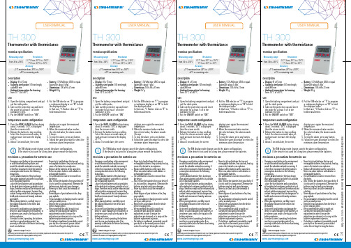
Thermometer with thermistanceUSER MANUAL Do not throw your electronical device with domestic waste. Once returned, required waste collection will be assured in the respect of the environment in accordance with European guidelines relating to WEEE.Throwing a used battery in the environment or with household waste pollutes and Precisions & precautions for batteries useThermometer with thermistanceUSER MANUAL Do not throw your electronical device with domestic waste. Once returned, required waste collection will be assured in the respect of the environment in accordance with European guidelines relating to WEEE.Throwing a used battery in the environment or with household waste pollutes and Precisions & precautions for batteries useThermometer with thermistanceUSER MANUAL Do not throw your electronical device with domestic waste. Once returned, required waste collection will be assured in the respect of the environment in accordance with European guidelines relating to WEEE.Throwing a used battery in the environment or with household waste pollutes and Precisions & precautions for batteries useThermometer with thermistanceUSER MANUALDo not throw your electronical device with domestic waste. Once returned, required waste collection will be assured in the respect of the environment in accordance with European guidelines relating to WEEE.Throwing a used battery in the environment or with household waste pollutes and Precisions & precautions for batteries use。
企业信用报告_浙江瑞氏护理用品有限公司

目录一、企业背景 (5)1.1 工商信息 (5)1.2 分支机构 (5)1.3 变更记录 (5)1.4 主要人员 (7)1.5 联系方式 (7)二、股东信息 (8)三、对外投资信息 (8)四、企业年报 (8)五、重点关注 (9)5.1 被执行人 (9)5.2 失信信息 (10)5.3 裁判文书 (10)5.4 法院公告 (10)5.5 行政处罚 (10)5.6 严重违法 (10)5.7 股权出质 (11)5.8 动产抵押 (11)5.9 开庭公告 (11)5.11 股权冻结 (11)5.12 清算信息 (12)5.13 公示催告 (12)六、知识产权 (12)6.1 商标信息 (12)6.2 专利信息 (13)6.3 软件著作权 (13)6.4 作品著作权 (13)6.5 网站备案 (13)七、企业发展 (13)7.1 融资信息 (13)7.2 核心成员 (14)7.3 竞品信息 (14)7.4 企业品牌项目 (14)八、经营状况 (14)8.1 招投标 (14)8.2 税务评级 (14)8.3 资质证书 (14)8.4 抽查检查 (15)8.5 进出口信用 (15)8.6 行政许可 (15)一、企业背景1.1 工商信息企业名称:浙江瑞氏护理用品有限公司工商注册号:330185000038445统一信用代码:913301856917156373法定代表人:周雄鹰组织机构代码:69171563-7企业类型:有限责任公司(自然人投资或控股的法人独资)所属行业:其他制造业经营状态:开业注册资本:5,000万(元)注册时间:2009-07-16注册地址:临安市玲珑街道兴禹街258号营业期限:2009-07-16 至 2029-07-15经营范围:销售:卫生用品、纸制品、日用百货、办公设备、包装材料、工艺品、化工原料(除危险化学品及易制毒化学品)、五金机电、装饰材料、纺织品、钢材、水泥;货物进出口(法律、行政法规禁止经营的项目除外,法律、行政法规限制经营的项目取得许可后方可经营);其他无需报经审批的一切合法项目。
DH-300电子密度计说明书
苏州凯特尔仪器设备有限公司
DH-300/DH-600 电子密度计
DH-300/600
电子密度计
中 文 操 作 说 明 书
苏州凯特尔仪器设备有限公司
DH-300/DH-600 电子密度计
目录
一、概 论 ----------------------------------------------------------------1 (一)、原理 --------------------------------------------------------------1 (二)、用途 ---------------------------------------------使机台承受超出力量之压迫。 (二)、本机台之外表须以干布擦拭,勿使堆积灰尘。 (三)、本机如长时间不使用,应将装水之水槽取下。 (四)、本机应避免碰撞、挤压及潮湿,如长时间不使用,请将电源取下,并以防尘罩盖妥。
九、故障排除 (一)、重量不稳定:
排除方法:将测量台及水槽取下,看支持台下方是否有无异物或水滴。若有异物或水滴请先将异物 取出或将水滴擦拭干净。
4、将样品放入水中吊栏台上,稳定后按 MEMORY 键。
出现 SAVE_b 再出现---------表示扫瞄过程中
Nacha 多温区金属浴 使用说明书
Nacha 多温区金属浴使用说明书莫纳生物莫纳苏州4000平米 ISO9001、13485 标准工厂莫纳武汉6000平米 GMP 标准洁净工厂上海运营中心公司营销总部莫纳生物简介莫纳生物科技有限公司由珠海南山投资有限公司等机构发起,联合国内外多家知名生命科学企业携手打造。
公司集研发、生产、销售、服务于一体,致力于成为生命科学基础科研产品、生物技术企业研发工具及高标准生产原料的全产业链提供者,塑造生命科学行业的著名品牌。
研发生产基地莫纳生物现拥有莫纳苏州研发、生产基地、莫纳武汉生产基地,建成莫纳生物技术研发院。
构建了完整的研发,生产,质控,市场,销售管理,客户服务体系,旨在促进产学研合作、研发成果转化和企企合作。
依据QbD (质量源于设计)原则建立系统质量控制体系,做高标准、稳定、可靠的生命科研工具。
莫纳生物技术研发院由12名知名科学家担任顾问,10多位博士领衔近百名研究人员,以生物学应用为导向,研发更智能、高标准的生命科研工具。
重要说明本文件版权归莫纳生物科技有限公司(以下简称莫纳生物)所有,未经莫纳生物授权,不得对文件中的内容进行修改、挪用或恶意传播。
注意:使用前请您仔细阅读本使用说明,严格按照说明进行操作。
否则,有可能造成设备损坏或无法正常工作。
一、仪器安装1.开箱仪器开箱后,应首先按装箱单清点验收包装箱内物品,如有缺失或损坏,请立即告知安装工程师或联系莫纳生物售后。
验收合格,请填写仪器验货安装报告上相关内容,并交给安装调试工程师,以便建档和保修。
开箱取出仪器后,请妥善保存包装箱和包装材料,以便二次运输时使用。
对于送修运输途中因包装不善而发生的仪器损坏,莫纳生物不承担任何责任。
2.仪器安放本仪器应安放在湿度较低、灰尘较少且远离水源(如水池、水管)的地方,并保持室内通风良好,无腐蚀性气体或强磁场干扰。
为保证运行安全,在仪器方圆30 cm内不得有其他设备或杂物,不要将仪器放在难以实行断电操作的位置。
灵气昆仑,默默静守
灵气昆仑,默默静守作者:来源:《医学美学美容·蜜ME》2014年第12期品一杯淡雅清新的芳草茶,进行一次引人心醉的熏香典礼。
开阔心胸,着眼自然,去感悟汲取,天地间的宇宙生命能量,这是灵气疗法的魅力,这里是Reiki SPA。
编辑/晚晚本期推荐会所/瑞极水疗(北京昆仑饭店)编辑印象如果渴望在闹市中得到静修,不妨到水疗中心彻底放松一下;如果想要给全身的疲惫找一个出口,也可来水疗中心积聚新的能量。
北京最繁华的燕莎商圈和国贸CBD内,有一处隐匿于喧杂闹市中的桃源仙境。
循着精油的香气,来到香味最浓郁处——酒店的水疗中心。
这里以原木为主色,调配以多种植物,崇尚简约环保,注重减压养生,在低调内敛中尽显奢华与尊贵,是具有中国特色的现代感的水疗中心。
房间里昏暗的灯光与点点烛光让人倍感舒适,紧张的心情随之而慢慢平静,疲惫感也消失于无形。
这绝对是一个对的选择:在瑞极水疗(Reiki SPA)寂静独处,让心灵洗净浮华,让天地灵气灌注身心每一处角落……环境特色瑞极水疗(Reiki SPA)位于北京昆仑酒店3楼,占地面积约800平米,共有8间单人理疗室、2间豪华VIP双人理疗室和1间维其浴室,提供绝对私密的休闲空间。
超过100平米的VIP套房,使用世界顶级按摩浴缸和纯手工制造的水晶吊灯——所环绕着的梦幻般的渐变灯光,有着色彩疗法的神奇功效。
此外,Reiki SPA还可以通过由美国食品及药物管理局FDA认证的“人体经络能量分析仪”,分析全身经络当下的运行状态,并根据此量身定制专属的理疗及养生建议书。
这里的每一位芳疗师都经过国际SPA协会认证的培训师严格的训练,熟练掌握多种经典的理疗手法。
瑞极(Reiki)出自古梵语佛经,意为天地之灵气,原为藏传佛教修炼身心的一种自然疗法,最早起源于藏传佛教圣地昆仑山,19世纪被Mikao Usui大师重新挖掘整理出来,形成了如今流行于欧美和东南亚的Reiki自然疗法。
瑞极水疗(Reiki SPA)是国内唯一一家以藏传佛教“灵气”(Reiki)为主题的水疗会所,融合了传统中医、日本茶道、印度能量平衡和欧洲芳香疗法的经典智慧,凝炼出自身独特的能量护理疗程,以自然和谐的理疗艺术使身体和心灵趋于完美平衡。
HR300系列脱水器用户手册说明书
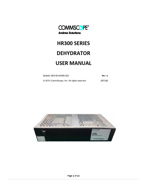
HR300 SERIESDEHYDRATORUSER MANUALBulletin AE01B-A0595-002Rev: A © 2015 CommScope, Inc. All rights reserved(07/15)HR300 SERIES DEHYDRATOR USER MANUALContentsSection 1General Information (3)1.1Introduction (3)Section 2Safety Information (3)Section 3Equipment (4)3.1Supplied Equipment (5)Section 4Description (6)Section5Installation (6)5.1Unpacking (6)5.2Mounting (7)5.2.119” Rack M ounting (7)5.2.2Wall Mounting (7)5.3Electrical Connections (7)5.3.1Power Connections (8)5.3.2Power Connections (8)5.4Pneumatic Connections (8)5.4Operation (8)5.6Alarms (9)Section 6Corrective Maintenance and Spare Parts (9)Section 7Outline (10)Section 8Customer Service (10)8.0Introduction (10)8.1In Case of Trouble (11)8.2Initial Steps by CommScope (11)8.3Repair Center Process (11)HR300 SERIES DEHYDRATOR USER GUIDE MANUALSection 1 General Information1.1 IntroductionThe HR300 is a heat regenerative air dryer. Itutilizes redundant compressors and dryingcanisters to insure a reliable flow of dry air forpressurization of air cable. The canistersautomatically regenerate, eliminating themaintenance associated with typical desiccantdryers.The HR300 must be located such that onlyauthorized personnel have access.CAUTION: The HR300 utilizes heat toregenerate the drying canisters. Mount theHR300 at the top of the equipment rack ifpossible. Should be placed in the top of theequipment rack with nothing mounted aboveit. A minimum gap of at least one rack unitshould be left unused above the dehydrator.Section 2 Safety InformationMake sure that the information in thisdocument has been understood by the personsperforming the procedures:•Electrical Hazard! Unplug power cordbefore servicing unit.•Let unit cool before removing cover.HR300 SERIES DEHYDRATOR USER MANUAL Section 3 Equipment3.1 Supplied EquipmentAdditional Accessories (sold separately)HR300-KIT-ETSI HR300 ETSI N3 RACK BRACKETS KITHR150-KIT-ACDC HR300 AC TO 48 V DC POWER CONVERTER KITMT/HR-KIT-HUMIDITY Humidity Sensor KitSection 4 DescriptionThe HR300 dehydrator system is designed for continuous automatic operation. It is a heat regenerative desiccant dehydrator designed to operate on -48 / -60 V DC. The desiccant automatically regenerates by periodic heating and requires no scheduled maintenance. It will supply up to 300 liters per hour (10.6 scfh) of air with a dew point of better than –45°C (–49°F) at a nominal pressure of 3 kPa (0.44 psig).The HR300 is designed for mount in a standard 19” equipment rack and has an option for ETSI N3 rack-mounting with adapter plates (sold separately). The HR300 requires 2 rack units to mount.Dry air is supplied to the transmission lines by four independent outlets located on the rear of the chassis.Ambient air is drawn through desiccant beds by two low power diaphragm compressors. The adsorbent material in the desiccant canisters removes moisture from the ambient air prior to passing it through the internal manifold where the system pressure and humidity level (optional) is monitored.System pressure dictates demand and theHR300 will respond by changing the speed of the compressors allowing the dehydrator to function without pressure switches or regulators. This increases compressor life and overall unit reliability. Section5 Installation5.1 UnpackingThe HR300 includes all necessary brackets andelectrical terminations to successfully install theunit in a site.Installation of the HR300 requires the followingtools:•#1 and #2 Phillips head screw drivers•Wire cutters and wire strippers foralarm terminationsJ2 Alarm Connection4 OUTPUT PORTS-48/-60 DC POWER CONNECTOR5.2MountingCAUTION: The HR300 utilizes heat to regenerate the drying canisters. Mount the HR300 at the top of the equipment rack. The heat created by the HR300 is dissipated out of the top and side of the dehydrator. DO NOT mount any equipment above the HR300.5.2.1 19” Rack MountingAttach the supplied rack brackets with theincluded screws to the front mounting holes for installation in a standard 19” equipment rack as illustrated below. The hardware necessary for mounting to the equipment rack is not included5.2.2 Wall MountingInstall the standard 19” rack brackets on the rear of the chassis with the included screws as illustrated below. The brackets will provide enough clearance for the tubing and electrical connections.Secure the unit to the wall using appropriate fasteners for the wall material. The hardware for mounting to the wall is not included.5.3Electrical ConnectionsCaution: The ON/OFF switch on the front must be switched off prior to disconnecting the dehydrator from the power supply prior to servicing.A protective earth terminal is available through the power connector J1 and is marked by the Earth Ground symbol.Additionally, there is an external ground stud that can be used for additional electrical protection.5.3.1Power ConnectionsVerify that the power supply is the correct type and rated voltage prior to connecting theHR300. See power ratings label on rear side of the dehydrator.The power cable comes pre-terminated for connection to J1 on the rear of the dehydrator. The HR300 incorporates reverse polarityprotection. If the unit does not power up when connected to the DC supply, verify polarity and correct if necessary. The supply end of the power cable is left un-terminated to accommodate any type of power supply. If the proper DC power supply voltage is connected to the dehydrator and the power switch is turned on but the unit fails to operate, verify the polarity. If the polarity is incorrect, have it reversed and then re-connect to the dehydrator. The HR dehydrators are equipped with reverse polarity protection, but will not operate under reverse polarity. Polarity for the power cable is: Red – Positive Black – Negative White - Ground5.3.2Alarm ConnectionsAlarm wiring will need to be provided by the customer at the installation site.5.4Pneumatic ConnectionsThe HR300 has a quantity of four 9.5 mm (3/8 in) compression fittings located on the rear of the chassis. The dehydrator is shipped with one port open to ambient air. The other three ports are plugged with pressure caps in order to prevent air from escaping from these ports when not in use. In order to use theseadditional ports, simply remove the pressure caps.5.4OperationConnect the included tubing to an open port on the rear of the unit. All unused ports must beplugged with pressure caps. Turn on the power switch located on the front face. The LED will illuminate.The first compressor will start and air will beginflowing to the transmission line(s).If this is a new installation, the transmissionlines must be purged by creating a small leak atthe far end of the transmission lines andallowing the dehydrator to pump dry air throughthem.A minimum of three air volume exchanges isrequired. If the installation is located in a veryhumid area, up to twelve air exchanges may benecessary to properly purge the transmissionline. The time, in hours, necessary to exchangethe air one time is based on the total air volume(V) of the waveguide and antenna system.Purging time (hours) = (3 x V) / 300, where V isline volume in litersAt the conclusion of the purging cycle, close thefar end of the transmission lines.5.6 AlarmsThe HR300 is equipped with an LED on the frontpanel for a visual indication of alarm conditions.A green LED indicates all is well with thedehydrator. A solid or blinking amber LEDindicates a problem with the dehydrator.Blinks Alarm DescriptionSolid Amber SystemFailureIndicates a failure of thecontroller. Replacement will benecessary.1 HighHumidity(optional)Indicates output air is above 10%RH. This can be caused by longstorage periods and should clearin the first 24 hours of operation.2 LowPressureIndicates a system pressurelower than alarm threshold.3 HighPressureIndicates a system pressurehigher than alarm threshold.If multiple alarms exist at the same time, theywill blink in sequence with approximately twoseconds between.Front of ChassisRear of ChassisSection 6 Corrective Maintenance and SparePartsThe HR300 is designed to be maintenance free.If you experience any issues with the HR300,please contact CommScope. See Section 8 foradditional information.ALARMSYMBOLSALARMOUTPUTWIRES COLBLACK (NOWHITE (CORED (NC)Section 7 OutlineOutline without mounting bracketsOutline for 19’’ rack and wall mountingOutline side viewOutline side view wall mountingSection 8 Customer Service8.0 IntroductionCommScope provides in-warranty and out-of-warranty repairs as well as dehydrator and Centers. Coordination of these services is provided through the nearest Sales Office or Customer Service Center. The Center is also prepared to help you with the following: •Technical Assistance•Repairs•Loaner Units•Spare Parts•Installation Materials•System Accessories8.1 In Case of TroubleThe first step you should take if troubledevelops using a dehydrator is to read theoperators manual and follow the troubleshooting procedures given in it.Symptom Potential SolutionPump Not Running Cycle power of the unitVerify pumps are connected to PCB Open output port and verify pump speed increasesLow Pressure Alarm Unused output port not capped Transmission line open/leaking Internal tubing disconnected / leakingHigh Pressure Alarm Very small system volume; allow unit pressure to settle over 20 minutesHigh Humidity Alarm Leaking desiccant canister end plate Insufficient system purgeUnit Will Not Power Up DC Power polarity may be reversedLoose or disconnected wire inside of the unitIf the steps in the manual do not identify and remedy the problem, then contact a CommScope Customer Service Center for 24–hour telephone assistance. Record the Model Number (e.g. HR300) and Serial Number from the product label, as you will be asked for these when you call. Two main locations are currently available to help:From North America•Telephone: 1-800-255-1479•Fax (U.S.A.): 1-800-349-5444 International•Telephone: +1-779-435-6500•Fax Number: +1-779-435-8579Web Access•Internet: w •email: #*****************8.2 Initial Steps by CommScopeWhen your call or fax communication isreceived, the CommScope staff will work withyou to pinpoint the possible cause of trouble. Ifthe pressurization equipment is suspect, theywill:•ask for your unit Model Number and SerialNumber•check the warranty status of the unit•advise the availability of a loaner unit•provide an estimate of the cost forinspection and repairs, if the unit is out–of–warranty•fax a Return Material Authorization Sheetto you8.3 Repair Center ProcessA method of Payment must be provided priorto issuing of RMA regardless of warrantystatus.I N–WARRANTY REPAIR: This CommScopepressurization product carries a warranty of oneyear. Warranty details are available on our webpage. If your unit falls within its warranty period,inspection and repairs will be performed at nocharge and the unit will be promptly returned toyou. If a warranty unit is deemed no problemfound an inspection fee and freight will becharged to the customer.OUT–OF–WARRANTY REPAIR: We will informyou with the cost of repair and obtain yourapproval to proceed with repairs or, if you electnot to have the unit repaired, your instructionson disposition of your unit. When repairs arecomplete, we will return your unit and invoiceyou for the inspection charge, materials used forthe repair and labor applied to complete therepair. If you elected not to repair the unit, wewill invoice you for the inspection and freightcharge if unit is to be returned.LOANER UNITS: Loaner units may be availablefrom the repair center to maintain your systemwhile repairs are being performed. If you feelyou need a loaner, please contact us at one ofthe contact numbers. If a loaner unit isavailable, a P.O. for the full value of the unitmust be issued prior to shipment. Also contactus when the loaner is ready to be returned sothat we can issue a NEW RMA number toPage 11 of 12identify your return and create the appropriatecredit to your account. Damages to loaner willbe deducted from the P.O.PACKING INSTRUCTIONS: Pack your unitsecurely for shipment to the Repair Center. Ifyou received a loaner unit, we suggest you usethe box and packing materials to return yourunit. Otherwise we have factory packingmaterials available for a nominal fee. Enclose acompleted copy of this form inside the box andclearly mark your Company Name and RMA:XXXXXXX on outside of the box. Address the boxto the following Ship–To Address:CommScope Pressurization Service CenterRMA# XXXXXXX11312 S. PIPELINE RD.EULESS, TX. 76040-6629Please note, Units received withBiological/animal contamination will bereturned unrepaired or scrapped afternotification and you will be invoiced forinspection and freight.CONTACT NUMBERS: If you have any questionsabout the repair process or status of your unit,please contact us directly through one of thefollowing methods – Telephone (below)TEL: 817-864-4155FAX: 817-864-41798.4 RoHS InquiriesFor inquiries on RoHS please contact thefollowing:CommScope Inc.Corke Abbey, Bray Co.,Dublin, Ireland ArrayAttn: Legal DepartmentPage 12 of 12。
PTC介绍说明

一、PTC热敏电阻简介1. PTC发热元件安装安全保护装置。
当使用不正常时,电流会自动切断,以维持安全。
2. 加热元件都整合在一起,由平均采暖效果。
当用于加热器,它可以独立控制单PTC(500W,800W),双PTC(1000W,1500W)或三重PTC发热元件(1500W,2000W),有效节约电力成本,提高了产品的使用寿命。
3. 极和终端的连接点焊接,防止电极松动导致耐温度增加时加热,冷收缩或热的通胀。
4. PTC加热元件的外边缘被设计与单和双重绝缘的。
与金属接触时不会造成触电或短路。
5. 紧紧密封,电极加热元件是密闭/未曝光。
最适合应用在浴室或湿度高的场所。
6. 它被安装与双重绝缘加热装置,可在水中使用而不会造成漏电或短路,加热干燥时,它不会破裂或烧毁容器。
7. 无异味,无辐射和不会氧化或用于很长一段时间时,会导致氧短缺。
8. 快速热响应时间,低浪涌电流。
会不会引起火灾火花或火焰瞬间/突发性的电源供应器或与易燃物品,如火柴,棉花,纸张接触时。
9. 没有所需的各种温度的选择,温度控制装置。
静态加热,降低产品成本,并有效地节省电力。
10. 加热组件不仅可以用于在加热器风扇,其各个组成部分也可以被用于一般家庭用品电力家电1. PTC发热芯特点1.没有温控器重新2.几乎无限的生命3.无运动部件磨损4.非常低的成本5.无电噪声6.的温度越高,更多的电力效率7.不燃烧时,在造纸,火柴或衣服接触+0.1典型应用• 热风扇 • 加热板 • 烘干机 • 电吹风 • 直发器 • 卷发器 • 暖脚•柴油/燃油加热器•PTC加热元件(圆盘型)典型应用•自我控制加热元件•烘干机•加热板•化油器预热•特别设计的尺寸或最大。
表面温度也。
•2、PTC热导体PTC热传导特性加热效率高低电力消耗低成本可在宽电压范围(12V〜600V)高可靠性与自我调节特性加热功率(W)和自调节功能是在相关的周围环境(温度,空气流量,空气体积)最适合的加热,保温,恒温保持,具有几乎无限的应用!PTC热导体应用PC主板的保护,在缺氧条件下维持恒定的温度,以保护电子元件故障。
HT300中文说明书+++
HT300里氏硬度计用户手册(使用前务必详细阅读)版本国标:GB/T17394-1998检定规程:JJG747-91(参照瑞士标准)北京时代新天科贸有限公司出品1 概述--------------------------------------------------1产品特点----------------------------------------1主要用途及适用范围----------------------------- 2品种规格--------------------------------------- 5工作条件--------------------------------------- 82 结构特征与工作原理---------------------------------- 9结构特征--------------------------------------- 9工作原理--------------------------------------- 113 技术特性-------------------------------------------- 11技术参数--------------------------------------- 11尺寸重量--------------------------------------- 134 使用------------------------------------------------- 13使用前的准备和检查----------------------------- 13测量------------------------------------------- 145 特别提示--------------------------------------------- 176 操作详解--------------------------------------------- 18开机------------------------------------------- 18关机------------------------------------------- 18测量------------------------------------------- 18菜单结构图------------------------------------- 22测量条件设置----------------------------------- 23打印功能--------------------------------------- 27存储管理器------------------------------------- 30浏览界面--------------------------------------- 33系统设置--------------------------------------- 34软件信息-------------------------------------- 36软件校准-------------------------------------- 37背光------------------------------------------ 37自动关机-------------------------------------- 38电池的更换------------------------------------ 38数据传输电缆连接------------------------------ 387 故障分析与排除-------------------------------------- 388 保养和维修------------------------------------------ 39冲击装置--------------------------------------- 39正常维修程序----------------------------------- 399 检定周期-------------------------------------------- 3910 用户须知-------------------------------------------- 3911 贮存条件、运输及注意事项-----------------------------40合格证------------------------------------------------- 41装箱卡------------------------------------------------- 42保修登记卡--------------------------------------------- 431概述产品特点依据里氏硬度测量原理,可以对多种金属材料进行高精度检测。
美国玻璃水技术有限公司产品说明书:SSC系列蒸汽水泳池电源

STRIVE FOR CLEAR WATERSAA Model: SSC SeriesEMSW2107104112. TERMS OF THE WARRANTYAs original purchaser of this equipment have purchased from Emaux Water Technology Co Ltd, through Authorized International Distributor or Dealer, warrants its products free from defects in materials and workmanship under normal use during warranty period. The warranty period begins on the day of purchase and extends only to the original purchaser. It is not transferable to anyone who subsequently purchases the product from you. It excludes all expendable parts.During the warranty period, Emaux authorized reseller will repair or replace defective parts with new parts or, at the option of Emaux, serviceable used parts that are equivalent or superior to new parts in performance.This Limited Warranty extends only to products purchased from Emaux authorized reseller. This Limited Warranty does not extend to any product that has been damaged or rendered defective (a) as a result of accident, misuse or abuse;(b) as a result of an act of God;(c) by operation outside the usage parameters stated herein;(d) by the use of parts not manufactured or sold by Emaux;(e) by modification of the product;(f) as a result of war or terrorist attack; or(g) as a result of service by anyone other than Emaux authorized reseller or authorized agent.EXCEPT AS EXPRESSLY SET FORTH IN THIS WARRANTY, EMAUX MAKES NO OTHER WARRANTIES EXPRESSED OR IMPLIED, INCLUDING ANY IMPLIED WARRANTIES OR MERCHANTABILITY AND FITNESS FOR A PARTICULAR PURPOSE. EMAUX EXPRESSLY DISCLAIMS ALL WARRANTIES NOT STATED IN THIS LIMITED WARRANTY. ANY IMPLIED WARRANTIES THAT MAY BE IMPOSED BY LAW ARE LIMITED TO THE TERMS OF THIS EXPRESS LIMITED WARRANTY.Installation template Ratio 1:1ELECTRICAL WIRING P14HYPERTHERMIAAlways unplug the device from its socket or power source and allow it to cool before opening the enclosure. There is high risk of shock and burn injuries from touching the internal component.COMPRESS AIR HAZARDOUSSAFETY WARNINGS P21. SAFETY WARNINGSThis appliance must be installed in accordance with national wiring codes and with a means of disconnection incorporated in any fixed wiring.High voltage can shock, burn, or cause death or serious property damage.1. In order to reduce the risk of electric shock DO NOT use an extension cord to connect the unit to electric supply.2. If the supply cord is damaged, it must be replaced by the manufacturer, its service agent or a qualified electrician.3. The system must be permanently connected to an individual circuit breaker, especially when pump power is connected from pump socket of the device.4. This electricity supply must be connected through a residual current device (RCD) or Ground Fault Circuit Interrupter (GFCI) with a rated residual operating current not exceeding 30 mA.5. Electrical grounding must be connected before connecting to electrical power. Failure to ground all electrical equipment can cause electric shock or serious or fatal injury.6. Before servicing, unplug the power plug from the electrical socket and allow the device to cool for at least 15 minutes.7.Never unplug the cell cable during operation.This appliance can be used by children aged from 8 years and above and persons with reduced physical, sensory or mental capabilities or lack of experience and knowledge if they have been given supervision or instruction concerning use of the appliance in a safe way and understand the hazards involved. Children shall not play with the appliance. Cleaning and user maintenance shall not be made by children without supervision.This system enclosed titanium cell in a plastic enclosure that can become pressurized. Pressurized air can cause the plastic enclosure to explore causing serious injury or death. The cell must be operated with the pump running and the valves fully open allowing water to flowunrestricted through the cell enclosure.This device is intended for use with swimming pools and spas only; it must not be used for disinfecting drinking water.Only one pump and one underwater light may be connected to this unit (SSC-TLT Series Only) The current loading of the pumped connected must not exceed 8 Amp. ( SSC-TLT Series Only)Top CoverTransformer240V 220V 0V Cell Drive ModuleMain PCBFuseSwitchPower CordWhite Color for 220VacCell Cable Socket2 3 1C2C1Blue Color for 230/240Vac White Color for 220VacTop Cover240V 220V 0V TransformerMain PCBFuseC2C1TimerLNEMC BoardCell Drive Module2 3 1Pump Socket Cell Cable SocketPower CordSSC15/25/50E WIRING DIAGRAMSSC15/25/50-T WIRING DIAGRAM11. CLEANING THE TITANIUM CELLAlthough the system is designed with a self-cleanig function for the cell (reverse polarity), it will occasionally be necessary to manually clean the cell to remove calcium deposit.enclosure, the pump and salt chlorinator will stop automatically.CautionAThe mixture required for cleaning is extremely corrosive and protective clothing should be worn. Procedures.Make up a dilute mixture of 1:10 parts of Hydrochloric (muriatic) Acid to water 1. Turn the filtration system off.2. Remove the salt cell from the housing.3. Add the salt cell to the cleaning mixture making avoiding contact with the terminals.4. Wait five to ten minutes for the Salt Cell to be cleaned.5. If any parts of calcium are stuck or will not dissolve, carefully remove them with a smooth plastic instrument.6. Once the salt cell is clean, rinse with fresh water and place back in the housing and tighten the cell or collar.7. Turn system back to automatic setting or timer. Dispose of cleaning mixture.Always add Hydrochloric acid to waterIf the salt cell has a heavy deposit of calcium that has not been removed after ten minutes in the cleaning solution, we recommend using a "Cell Cleaner" product which is not as corrosive as hydrochloric acid. The cell can then be left in the cleaner for up to a hour and will completely remove the calcium.We recommended using SaltCell Cleaneratall times over the traditional Hydrochloric mixture, it is a safer alternative and not harmful to your Salt Cell at all and reusable.Blue Color for 230/240Vac P13 ELECTRICAL WIRINGP3 SAFE POOL SANITIZING WORKING PRINCIPLE Chlorine is a highly effective sanitizing agent which is commonly used in swimming pools. It can prevent the growth of bacteria and fungi. This chlorinator uses the process of electrolysis to break down the salt (NaCl) in the swimming pool water to produce chlorine gas (Cl©ü Chlorine production can be regulated from the control unit by altering the electric current flowing through the titanium electrode in the cell housing.) 2. SAFE POOL SANITIZING WORKING PRINCIPLEIt is important to note that the EMAUX Chlorinator does not maintain the water chemistry of your swimming pool water; it simply produces chlorine from a mild salt solution.To ensure that your chemical balances is within the guidelines listed below and to encourage a sparling clean, you should also have your water tested regularly at your local pool shop.2.1 WATER CHEMISTRY:10.2 POWER MODULEA salt chlorinator is a valuable piece of pool sanitizing equipment. Regular care and maintenance will ensure the best performance and long life. Keep the water chemical balance1. Maintain the correct water chemical balance2. Maintain a good operating environment3. Regularly check the condition of the titanium plates. During the chlorination process white calcium scale may naturally build up on the titanium plates in the cell. Regular monitoring of the cell will prevent excessive buildup of scale. Excessive scale will damage the cell and significantly reduce its life and efficiency.4. If the control box fails orthere isexcessive calcium deposit, maintenance must be carriedout by a pool professional.5. Prevent insects from entering the control box, they may damage the electrical components inside.SSC15 & SSC25 no fuse SSC50 is 30A.10.3 TRANSFORMERThe transformer has two voltage inputs:240Vac (blue) for Australia, New Zealand and UK.220Vac (white) for rest of the world.Avoid burn injuries: Do not touch the transformer before switching it off and allowing it to cool.10.4 TERMINAL BLOCKThe terminal block in the middle of the chassis is used to select input AC voltage 220V or 240V, input power fuse protection and connection to transformer input.TROUBLE SHOOTING P1210. ELECTRICAL WIRING10.1 MAIN PCBThe main controller PCB has two connectors.1. 13 pins flat cable connector for the power module2. 4 pins cable connector, blue and gray color pins connect to the power switch.SAFE POOL SANITIZING WORKING PRINCIPLE P4The amount of salt required is between 4000 and 6000 ppm. This can be done by adding 4-6Kg of salt per 1,000 litres of water directly into the pool water.A low concentration of salt (below 2500 ppm) will cause premature cell failure.A High concentration of salt (above 6000 ppm) may cause electro-oxidation and corrosion damage to the Stainless Steel pool fixtures and fittings.Salt required according to the volume of the pool:3 Note: Table based on 4000 ppm of salt per m of water.2.2 CHLORINE LEVEL CALCULATION2.3 SALT LEVELP11 TIMER SETTING FOR TIMER VERSION 8. MAINTENANCE AND TROUBLESHOOTINGA salt chlorinator is a valuable piece of pool sanitizing equipment. Regular care and maintenance will ensure the best performance and long life. Keep the water chemical balance 1. Maintain the correct water chemical balance 2. Maintain a good operating environment3. Regularly check the condition of the titanium plates. During the chlorination process white calcium scale may naturally build up on the titanium plates in the cell. Regular monitoring of the cell will prevent excessive buildup of scale. Excessive scale will damage the cell and significantly reduce its life and efficiency.4. If the control box fails or there is excessive calcium deposit, maintenance must be carried out by a pool professional.5. Prevent insects from entering the control box, they may damage the electrical components inside.9. TROUBLE SHOOTINGThe most common salt used in swimming pools with Salt Electrolysis is 99% pure Sodium Chlorine (NaCl).DO NOT use the following types of salts:1. Rock salt.2. Salt with more than 1% yellow prussiate of soda.3. Salt with more than 1% of anti-caking additives.4. Iodized salt.2.4 TYPE OF SALTSalt with additives or impurities will cause premature cell failure.Before adding the salt into the pool, place the multiport valve on “ Filtration ” or “ Recirculation” and then turn the filtration pump on.2.5 ADDITION AND REMOVING SALT IN THE SWIMMING POOL WATERAdd the salt directly into the pool evenly around the pool or ballast tank. Do not allow the salt to sit in a pile on the bottom of the pool.Do not add large amount of salt nearby the skimmer at the same time. It will damage the unit. Keep the filtration system running for 24 hours using the Main Drain or vacuum suction nozzle asa main suction line.The only way to remove the salt in the pool water is to partially drain the pool and refill with fresh water.3. PRODUCT FEATURES1. Convenience and the constant delivery of pure chlorine-based sanitizer.2. No more artificial chemical cleaning agent which could cause skin and eye irritation. You just need to add natural salt in the pool.3. The salt in the water is so little you do not taste or smell the salt.4. The electrode is made of titanium, which is durable and resistant to corrosion.5. Easy to install and operate.6. The water does not have the heavy smell of chlorine because chlorine is not directly added to the pool.Product Picture1 x control box 1 x cell unit 1 x cell cable1 set screws and Fuse 1 set 1.5” & 2” Universal Union User ManualLED DISPLAYOperationSystem ControlCell Polarity1GreenGreen Red ONGreen+Red2GreenRed Red OFF Red-RedDescriptionNormal OperationLow salt/Deposition on the electrode/Low water TemperatureExtremely low salt level / heavy deposition on the electrode /extremely low water temperature DescriptionSystem control less than 100%, under operating System control less than 100%, under idle time DescriptionThe cell current in positive directionThe cell current in negative directionSALT CHLORINATOR ON/OFF/AUTO: ON/Off Switch. In Auto mode, the chlorinate is operated by the timer setting.Light On/Off: Switch for underwater light connected to the control unit (For certain models)System Control button: Adjust the length of time of chlorinator production. For example: 76Set at 100% = the salt cell operate continually.Set at 50% = the salt cell operate for 30 minutes in each hour and is idle for 30 minutes.Set at 30% = the salt cell operate for 18 minutes in each hour and is idle for 42 minutes.Winter Mode Switch and On/ Off LED: Turn on to change the chlorine production to 85% of the system production setting.Cell Polarity LED: Shows the polarity of the electrodes; the polarity of the electrode will reverse every 8 hours, in order to remove any deposit on the electrode.Timer: (timer models only) Programs the on and off times for the unit and pump to run automatically.Stand-By LED: Displays when the chlorinator is in stand-by mode. When the chlorinator is turned on, the stand-by LED will go off after 35 seconds.No Flow LED: Displays when there is no water flow. If there is no water in the cell enclosure, the pump and salt chlorinator will stop automatically.1. Turn the clock face until the time of the day is aligned with the clock at the center of the timer hand.2. The 24-hour dial has 15 minutes division. The timer can be programmed by pushing the captive trippers to the outer ring position for the entire period that the load is to be turn ON.3. The timer clock will rotate with time; the chlorinator will be turned on automatically if its captive tripper is pushed outward.7. TIMER SETTING FOR TIMER VERSIONSSC-T Series(Chlorinator with time switch)PRODUCT FEATURES P63.1 PRODUCT DIMENSIONS3.2 PRODUCT SPECIFICATIONAll the cells are Self Cleaning typeSSC-TLT Series(Chlorinator with underwater light, transformer and time switch) P9 CONTROL PANEL OPERATION4. The control panel will display a RED indicator when the salt level is low.5. If no action is taken to rectify the salt level, damage to the cell may result which will not be covered underwarranty.6. During extreme hot weather conditions or high bather load, the pool water need to be super-chlorinated usingpowder, granulated, or liquid chlorine or the running time of the chlorinator should be increased.7. Always turn down the system control to zero before adding salt, once the salt is completely dissolved, return tothe set position.8. The aluminum casing at the back of the Control Unit acts as a heat sink, do not touch it with bare hands.6. CONTROL PANEL OPERATION6.1 DIGITAL DISPLAYThere are three display functions:1. When system control button is tuned from left to right, it adjust the cell output ratio and display thecorresponding running time per hour. For example, “100 “means 60 minutes, “50” means 30 minutes run and 30minutes idle.2. In normal operation, it represent the percentage of the chlorine production. “100” means 100% chlorine is beinggenerated with adequate salt level.3. System Error code, system stop and need attention* E R2- for protection, the system will stop operate when a worst environment is detected, such as too high saltlevel, high ambient temperature or insufficient ventilation.START UP P813. For model with power socket for pump, the maximum allowed power rating is 1,500 Watt or 1.5HP. Refer topump model plate for power rating confirmation. 14. DO NOT mount the Control Panel under direct sun light.15. The Control Panel must be installed far away from the chemical storage, especially from acid because it cancorrode the electronics inside the unit.16. It must be kept away from heat sources and any equipment which produce heat. 17. Plug-in power supply into a suitable weatherproof outlet socket with circuit breaker.18. Before fixing the Control Panel, make sure that the power cable and cell cable also reach the Control Panel. For model with built-in lighting power output:Mount the control unit vertically onto a post or wall 1.5 meters above ground level. (Australian Standardsrequires that the electric control unit shall not be located within 3 meters of the pool water.)4. INSTALLATION GUIDEThe Emaux SSC Chlorinator unit is contained in a rain tight enclosure that is suitable for outdoor mounting (IPX4 waterproof). However, the following points must be taken into consideration for a correct installation of the Superior SSC Chlorinator unit:1. Select a convenient well-ventilated location within one meter of filter equipment.2. The cell must be installed above the sand filter discharge outlet water level.3. If the chlorinator and cell are installed below water level, the pump and chlorinator must have a common power switch in o rder to prevent the chlorinator f rom generating chlorine while the pump is not running. Otherwise thecell enclosure will overheat and explode if only the pump is shut off.Typical system installation and Cell location with gate valve and water flow directionMounting Bracket4. Install the Control Panel using the template paper sheet provided with the package in a minimum distance of 3.5 meters (11.5 ft.) from the swimming pool, 1.5 meters (5 ft.) from the ground, within 2 meters (6.5 ft.) from the protected outlet, and within 4.5 meters (15 ft.) from where the cell will be installed, in a ventilated area and leaving enough free space of min. 50 cm (20”) in each side for servicing.5. Two self-tapping screws and wall plugs are provided for fast and simple installation. Simply cut out the template provided for the location of the drilling points. Use a 8mm masonry drill when fitting the control unit to a brick or concrete wall. When mounting to a post, drill pilot holes and fit the screws provided. Once the screws are in position simply hang the chlorinator via the bracket on back of the control box.6. The cell must be installed horizontally7. The electrolytic cell housing must be plumbed into the return line after the filter. The cell housing can be fitted to 1.5: or 2” PVC piping by provided universal union.8. Connect the water inlet and outlet to the Cell Unit. The water flow direction must be as indicated on the Cell.9. To avoid loss of chlorine, the Cell should be installed at the end of the filtration system, right before the pool water return.10. The cell should preferably be installed on a bypass with input and output gate valves. This will permit uninterrupted filtration while the chlorinator is being serviced. The inlet and outlet valves must not be closed during operation, otherwise pressure will build up in the plastic enclosure and it will explode.11. Glue the salt cell horizontally on the pool return pipe, allow the pipeglue to cure for 24 hours.12. Use the provided cable to connect the control unit and the salt celltogether.Water inWater outService By Pass Piping Power SupplyPowerPointPool LightCable(If fitted)1.5M MINCell CableCellPumpReturnWasteFilterPumpSuction RTPReturn to PoolPump CableNever allow the chlorinator operate without water flow. The pump and chlorinator must operate simultaneously.1. Recommended pool salt lever: 3000- 4000PPM for SSC15 and SSC25, 4000-5000PPM for SSC50.2. Run chlorinator at the Salt Levels stated within this document and on the product toensure optimum sanitizer output and cell life.3. Operating this device at low salt levels will damage the cell and reduce its life.5. START UP。
温度测量仪DTC-300的设置指南说明书
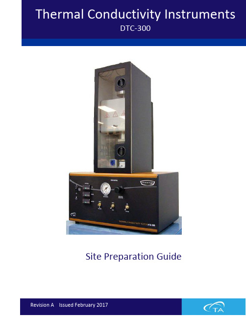
Thermal Conductivity InstrumentsDTC-300Site Preparation GuideTable of ContentsTable of Contents (1)Ideal Setup ................................................................................................................................... 2-3 System Components .. (3)Instrument Measurements (4)Utility Requirements (5)Power (5)Gas (6)Coolant (7)Water (8)Computer Requirements (9)Site Preparation Checklist (10)TA Instrument Offices (11)Ideal SetupIDEAL PLACEMENT AND BENCH MEASUREMENTSSelect a location with adequate floor space and a rigid laboratory bench that is level and is in a vibration-free environment.Bench length: 1.8 m (6 ft)Bench depth: 76 cm (30 in)Ideal Setup and ComponentsCOMPONENTSPlace the chiller on the same level as the instrument.A. ChillerB. InstrumentC. Computer (Controller)ABCInstrument Measurements INSTRUMENT MEASUREMENTSWidth: 64 cm (25 in)Depth: 71 cm (28 in)Height: 94 cm (37 in)Weight: 44 kg (98 lbs)POWERInstrument∙100–120 VAC, 10 A, 60 Hz (US)∙200–240 VAC, 10 A, 50/60 Hz (Non-US)∙Installation of a 16A Class B or C main fuse is recommended.Power cords providedUse power cords with plugs appropriate for your circuit.∙NEMA 5-15 plug for 100–120 VACOR∙NEMA 6-15 plug for 200–240 VACNEMA 6-15 plug NEMA 5-15 plugSupply voltages lower than indicated may result in a degradation of performance.Ensure that the mains assigned do not also supply power to noise generating equipment nearby, such as motors, welders, transformers, etc.An independent heavy GROUND wire must be provided through the power hookup. Improper grounding may cause severe damage for which the supplier will not accept responsibility. All power strips must be fully grounded and carry the ground through to the sockets into which the computer is plugged.GASPneumatic RamGas Requirements for Pneumatic Ram Type Must be nitrogen or airSource Must be from a gas cylinder, Grade 5 purityInlet Pressure Minimum: 40 psig (2.75 bar) Maximum: 50 psig (3.45 bar)Tubing ∙¼” tubing is supplied to connect f rom instrument to gas regulator∙Tubing is rated to 100 psig (7 bar)Purge GasGas Requirements for PurgeType Must be nitrogen; at sub-ambient temperatures to prevent frost and moisture buildup on internal metal componentsInlet Pressure Less than 5 psig needed–it is simply a low, steady flow to flush the furnace cavityTubing∙Purge gas port requires 1/8” tubing (provided)∙ A 1/8” stem to ¼” tubing adapter is also providedThe customer is required to supply either compressed air, dried and filtered, to 10 microns, or laboratory grade inert gas (such as nitrogen from a high pressure cylinder).COOLANTRequirementsPressure 4.3 psig (0.30 bar) maximumFlow Rate 20 L/min (5 gal/min) maximumOperating close to or below min. pressure will result inerratic operation.Cooling Capacity ∙At -20°C = 265W ∙At 0°C = 650W∙At +20°C = 1000WCoolant Liquid ∙50/50 mix of DI water and laboratory grade ethylene glycol for testing up to 300°C∙Denaturalized alcohol for sub-zero testingConnections Supplied: Two hoses (6 feet / 1.8 meters each) to connect to the Coolant Inlet and Outlet ports on the back of the furnace. The other end of each hose is blank; a male 3/8” barb with ¼” threads (provided) must be installed to connect to the coolant source.Place the chiller on the same level as the P/N 202612.001 (120V for 60Hz power) or202442.001 (240V for 50Hz power)Coolant Inlet and Outlet ports and hosesWATERExcessively cold water will result in “sweating” and corrosion of cooled metal surfaces. The purge of nitrogen gas through the furnace will prevent this.Operating below the minimum chiller coolant level will result in erratic operation. A chiller/circulator is recommended for this instrument.If a chiller/circulator is to be used, it must be placed at the same level as the instrument.Computer RequirementsHARDWARE REQUIREMENTS∙Unused RS-232 (serial) port∙Unused USB portInstrument drivers and software are provided on a CD.Computer should not be attached to other analytical instruments or LAN.SOFTWARE REQUIREMENTSItem RequirementOperatingSystem∙Windows 7 or 10, 32- or 64-bit, Ultimate, Enterprise & Professional∙Home version not supportedNetwork∙TA Instruments is not responsible for resolving issues associated withconnections to your corporate network.∙Network cards and/or certain network operation frequently interferewith the operation of the instrument and software.ConflictsTA Instruments is not responsible for resolving hardware/software conflictscreated by the addition of third party hardware or software to thecomputer.Site Preparation ChecklistThermal Conductivity Instruments: DTC-300 Sufficient bench space for instrument, computer, and chiller (if needed): ☐ Length: 1.8 m (6 ft)☐ Depth: 76 cm (30 in)Instrument power is☐ 100–120 VAC, 10 A max, 60 Hz (US)☐ 220–240 VAC, 10 A max, 50/60 Hz (Non-US)Computer, monitor, and chiller power is☐ 120 V (US)☐ 220–240 V, 6.4 A max, 50/60 Hz (Non-US)Pneumatic Ram Gas – Air or Nitrogen☐ Regulator to allow 40–50 psig (2.75–5.50 bar)Purge Gas – Dry Nitrogen☐ Under 5 psig (2.75–5.50 bar)Water Circulation☐ Nominal flow rate of 20 L/minute (5 gal/min)☐ Maximum pressure of 4.3 psig (0.30 bar)☐ Sufficient cooling capacity ☐ 50/50 mix of DI water and laboratory grade ethylene glycol (for temperatures up to 300°C)☐ Denaturalized alcohol (for sub-zero measurements) I hereby acknowledge that all utility requirements have been met per the checklist above and that they will be ready at the agreed time of installation.If all utility requirements are not met at the agreed time of installation, additional charges may be incurred for a return Service trip.CustomerDD MM YYYY CompanyCity State CountryPlease send a signed copy of the completed checklist to your local Service representative.TA Instruments Offices For information on our latest products, contact information, and more, see our website at: .To find your local TA Instruments office and contact information, visit/contact/ta-directory/TA Instruments – Waters LLCCorporate Headquarters159 Lukens DriveNew Castle, DE 19720USATelephone: 302-427-4000Fax: 302-427-4001Email: **********************。
- 1、下载文档前请自行甄别文档内容的完整性,平台不提供额外的编辑、内容补充、找答案等附加服务。
- 2、"仅部分预览"的文档,不可在线预览部分如存在完整性等问题,可反馈申请退款(可完整预览的文档不适用该条件!)。
- 3、如文档侵犯您的权益,请联系客服反馈,我们会尽快为您处理(人工客服工作时间:9:00-18:30)。
产品介绍:
DH300是采用微电脑控制的一款经济型干式恒温器,利用高纯度铝材料做为导热介质,以代替传统的水浴装置,外观精美、使用方便、精度高、体积小等特点。
可广泛应用于样品的保存和反应、DNA扩增和电泳的预变性、血清凝固等。
产品特点:
◆即时温度与倒计时显示
◆自动故障检测及蜂鸣器报警功能
◆温度偏差校准功能
◆内置超温保护装置
◆便捷的模块更换,便于清洁与消毒
◆外观精美,蓝色液晶显示即时参数信息
◆可选的断电自动恢复功能,开机自动运行功能,提高工作效率
◆智能算法,保证了全程范围内≤±0.3℃控温精度,有效降低实验误差
◆多重安全保护,保证长期运行的稳定性和无人值守情况下的安全性,符合CE标准
◆可按照客户要求定制模块
性能指标:
控温范围:室温+5℃~100℃
升温时间:≤15min (从40℃升至100℃)
温度稳定性@100℃:≤±0.3℃
模块最大温差@40℃:0.3℃
模块温度均匀性:≤±0.3℃
显示精度:0.1℃
时间设置最长:99h59min
电源电压:AC 220V/50~60HZ
功率:150W
外形尺寸:260×195×150mm
可选模块:
型号试管及孔径
MD30 96×0.2ml(标准版)
MD31 54×0.5ml(离心管)
MD32 35×1.5ml(离心管)
MD33 35×2.0ml(离心管)
MD34 15×0.5ml+20×01.5ml(离心管)MD35 96×0.2ml(酶标板)。
