SDR短波电台使用说明书
“巴克兰” 超短波电台试验器使用说明
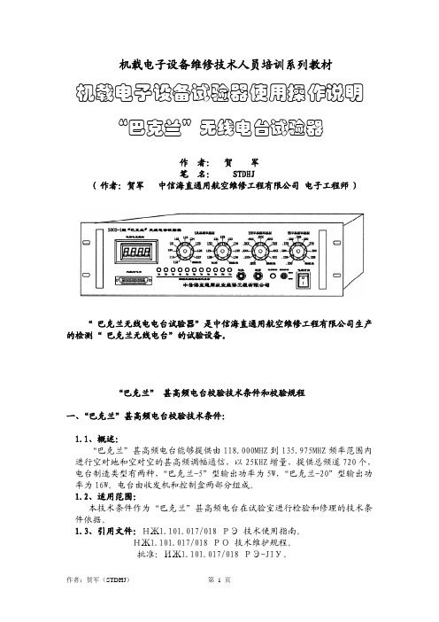
机载电子设备维修技术人员培训系列教材机载电子设备试验器使用操作说明 “巴克兰”无线电台试验器作 者: 贺 军笔 名: STDHJ( 作者:贺军 中信海直通用航空维修工程有限公司 电子工程师 )“ 巴克兰无线电电台试验器”是中信海直通用航空维修工程有限公司生产的检测“ 巴克兰无线电台”的试验设备。
“巴克兰” 甚高频电台校验技术条件和校验规程一、“巴克兰”甚高频电台校验技术条件:1.1、概述:“巴克兰”甚高频电台能够提供由118.000MHZ到135.975MHZ频率范围内进行空对地和空对空的甚高频调幅通信,以25KHZ增量,提供总频道720个,电台制造类型有两种,“巴克兰-5”型输出功率为5W,“巴克兰-20”型输出功率为16W。
电台由收发机和控制盒两部分组成。
1.2、适用范围:本技术条件作为“巴克兰”甚高频电台在试验室进行检验和修理的技术条件依据。
1.3、引用文件:НЖ1.101.017/018 РЭ 技术使用指南。
НЖ1.101.017/018 РО 技术维护规程。
批准:ИЖ1.101.017/018 РЭ-JIУ。
1.4、甚高频电台技术指标:1.4.1、电源电压:直流27.5V;输入保护10A保险丝。
1.4.2、接收电流:在直流27.V时≤1.1A。
1.4.3、发射电流:在直流27.5V时“巴克兰-5” ≤3.1A“巴克兰-20” ≤7.0A。
1.4.4、频率范围:118.000到135.975MHZ或者118.000到136.975MHZ。
1.4.5、频率稳定性:≤0.001%1.4.6、频道间隔:25KHz1.4.7、发射机调制器:1.4.7.1、射频功率输出:“巴克兰-5”输出5W;“巴克兰-20”输出16W。
1.4.7.2、输出阻抗:50欧姆。
1.4.7.3、调制能力:以音频信号为1000HZ,250mV进行调制,则发射机在整个频段内调制度为 80%—95%。
1.4.7.4、旁音输出功率:对发射机用100欧姆输入阻抗、1000HZ、250mV进行调制,输出旁音在500 欧姆负载为100毫瓦±1分贝。
低功率射频器材使用说明书

1080575 - 01/22WARNING !Keep batteries out of reach of children. Swallowing may lead to serious injury or death in as little as 2 hours due to internal burns. If swallowed, go straight to a hospital emergency room. Dispose of used batteries immediately.
取得審驗證明之低功率射頻 器材,非經核准,公司、商 號或使 用者均不得擅自變 更頻率、加大功率或變更原 設計之特性及功能。低功率 射 頻器材之使用不得影響 飛航安全及干擾合法通信; 經發現有干擾現象時,應 立即停用,並改善至無干擾 時方得繼續使用。前述合法 通信,指依電信管理 法規 定作業之無線電通信。低功 率射頻器材須忍受合法通信 或工業、科學及 醫療用電 波輻射性電機設備之干擾。
SDR#用户手册说明书

A USER’S GUIDE TO SDR# (SDRSHARP)SDR# (aka “SDRSharp”) is an easy-to-use yet small and fast Software Defined Radio application for Windows created by Youssef Touil with collaborative assistance from other talented software engineers. SDR# is written in C#, a modern, general-purpose, object-oriented programming language developed by Microsoft.SDR# is intended as a Digital Signal Processing application for use with a wide range of RF hardware, including:•SoftRock•FiFiSDR•FUNcube Dongle•SDR-4•LazyDog’s LD-1•SDR-IQ•SDR-14•RTL2832U / RTLSDR•Any sound card based SDR front end•Any ExtIO based SDR front endMore radios will be supported as interest demands. Latest information can always be found at the SDR# website: / and on the #SDR channel on IRC, or via the mail reflector:/group/SDRSharp/The SDR# human interface is intuitive and flexible to use. “Run” and “Stop” buttons are found the very top of the screen, along with the ability to select live data from a connected IQ stream or playback of stored files.The balance of the SDR# screen consists of three functional areas:-Expandable control panels along the left-hand side-Tuning controls and spectrum display at the top-right-Waterfall display at bottom-right-Controls for spectrum Zoom and waterfall Contrast along the rightmost edgeEXPANDABLE CONTROL PANELSSDR# comes with four standard control panels:o Radioo Audioo AGCo FFT DisplayEach panel can be minimized by clicking on the “-“ sign, or expanded by clicking on the “+” sign. RADIO:The Radio panel includes information needed to configure, control, and tune the Software Defined Radio. Here is a brief description of functions that are available:1. MODE Selections include Narrow FM (NFM), AM, Lower Sideband (LSB), Upper Sideband (USB), Wide FM (WFM), Double Sideband (DSB), and CW with lower or upper-side offset (CW-L and CW-U) NFM is used for all FM modes except FM broadcast, which is WFM.2. FREQUENCYThis box shows the frequency that is actually being received. Direct entry is possible, but must be within range of the center frequency that is presently set. Click the mouse anywhere in the spectrum display to tune to that frequency.3. CENTERThis box shows the center frequency that the RF front-end is tuned to. The combination of FREQUENCY and CENTER displays can be used to tune SDR#. Once the CENTER frequency is set, any signal within the spectrum display can be tuned, based on the sample rate of the RF front end. See “Spectrum Display” for information on tuning using the mouse, otherwise center frequency (in Hz) can be entered directly.4. FRONT ENDVarious RF hardware options can be selected by clicking the down-arrow just to the right of the FRONT END button. Available devices can be selected via the pull-down menu, and applicable defaults will be displayed.The FRONT END button brings up a menu containing any configuration options that are available for the selected device.5. FILTER TYPE, FILTER BANDWIDTH, FILTER ORDERThese three options allow customization of the window function, bandwidth, and order of the DSP filter used by SDR#. Default options are chosen for nominal operation in each model, but can be changed as desired, and the specified bandwidth will be shown as a highlighted area on the spectrum display. Filter settings will return to the default values when SDR# is restarted.6. SQUELCHClicking the box enables the Squelch function, which mutes the audio output until the received signal exceeds the threshold value that is determined by the value in the box below. Lower values “loosen” the squelch or decrease the signal level needed for audio to be heard. Higher values require stronger signals before audio is heard. Squelch is available in AM and NFM modes only.7. CW SHIFTThis value determines the offset between transmit and receive frequencies in the CW modes for devices having transmit capability.8. SNAP TO GRID, STEP SIZEThese functions help to simplify tuning for channelized operation, and to customize the tuning response of SDR# for all modes. A wide range of step size options can be selected from the pull-down menu to accommodate various needs. For example, 12.5 kHz steps are used in aircraft communications, whereas single sideband requires tuning in increments of 100 Hz or less. The Snap-to-Grid option forces the tuned frequency to the nearest step size increment.9. CORRECT IQSDR# has an original algorithm that compensates gain and phase imbalances between the IQ channels. Without this compensation strong signals are mirrored with respect to the center of the spectrum, as can be seen in the spectrum display of other SDR programs. This unique feature of SDR# should be left on unless there is a reason to disable it.10. Swap I and QMost RF front ends will present I and Q signals in the proper way, but if not, click this box to swap them without changing hardware connections.11.FM StereoWhen selected, stereo output is available in WFM mode (for broadcast FM listening)12.Mark PeaksClicking this box toggles a visual indicator of peaks in the spectrum display as an aid for tuning.USING THE SPECTRUM DISPLAYThe above settings should enable basic SDR# Radio operation using RTL-SDR / RTL2832 USB DVB-T dongle. Default frequency and mode settings are for FM broadcast where signals are strong and something should be heard even with a limited antenna.QUICK START: Select the Front End, Enter a Center Frequency and Mode, then click “Start”. Default settings should be sufficient for normal listening.ANTENNA: The short antenna supplied with DVB-T dongles provides poor reception and should be replaced with a good VHF-UHF antenna mounted outdoors if possible. Low-loss RG-6/U coax is readily available at reasonable price. Adapters can be purchased to adapt the “F” connector used on RG-6/U to the PAL connector used on the dongle. Alternatively the supplied cable can be cut near the end and used to make an adapter patch cable. Details for making inexpensive wideband VHF/UHF antennas such asthe discone can be found online. Old TV or scanner antennas, “rabbit ears”, etc can also be used.SPECTRUM DISPLAYThe spectrum display shows a continuous display of the RF spectrum. The amount of spectrum displayed is a function of three factors:1.The Sample Rate of the RF Front end. This determines the amount of RF spectrum that isdigitized and sent to SDR# for digital processing.2.The setting chosen in the “FFT Display” control panel.3.The setting of the “Zoom” slider to the right of the display area. Fully down, the amount ofspectrum displayed is the full amount that is provided by the RF Front End. As the slider ismoved up, the display zooms-in on the frequency presently tuned, showing more detail of thesignal being received, but less of the overall spectrum.The relative amplitude of each signal can be estimated by comparing the height of each peak. With practice one can quickly identify the different modulation types, based on their appearance in the spectrum display.Ability to easily tailor the spectrum display adds a great deal of capability to SDR#.The FFT setting determines the base resolution of the spectrum display. A fairly low FFT setting (such as 4096) provides adequate resolution for many purposes yet places a minimal burden on the CPU. Increasing the FFT provides much greater resolution, but at the cost of increasing the load on the PC CPU, with the highest settings requiring so much computational time that audio becomes choppy. The general rule of thumb is to use as high a setting as needed for your purposes, but no more.The zoom feature makes it easy to temporarily see more details without changing the base resolution. It is analogous to an old-time newspaper photo, where a magnifying glass enables you to see the dots that are always present in the image. Zooming-in on a signal makes it easier to tune to the exact center, and to view a limited chunk of spectrum in more detail.The mouse can be used to change the center frequency by clicking and dragging the background of the spectrum display to the right or left. Clicking on any part of the display area will tune SDR# to that frequency.OTHER EXPANDABLE CONTROL PANELSAUDIO:The Audio control panel allows control of the volume and selection of the audio source and destination. For most users the default choices will be OK. Those who need a source of unfiltered audio should unclick the “Filter Audio” box. For users who feed the output of SDR# to a digital decoding program of some sort, the Audio Output should be changed to Virtual Audio Cable or whatever alternative is used for this purpose.AGC:This panel provides control over the Automatic Gain Control feature of SDR#. Default settings should be OK for most users.FFT Display:Other than changing the resolution of the FFT as explained above, default settings should be OK for most users.CUSTOM:Developers are working on new features that add new functionality to SDR#, resulting in the addition of new expandable control panels for these features. If you have a version of SDR# that includes custom control panels, you will need to look to the SDR# website and discussion groups for further information. Some examples include:AUTO TUNER – automatically tunes to peak signals much like a scanner, including loggingfrequencies and other enhancements.TRUNKING – extracting control channel information from a 2nd dongle using Unitrunker toautomatically follow trunked radio systemThis ability to enhance SDR# will continue to evolve as the potential of software defined radio is explored and new applications created.WATERFALL DISPLAYThe waterfall display is a time-varying spectral display, and brings an exciting new dimension to radio listening. Previously used in applications such as sonar, speech processing, and seismology, the waterfall (also known as “spectrogram”) display gives us a brief look back in time as signals appear at the top, and then scroll down and off the bottom of the display. The frequency of each signal is the same as in the spectrum display above, so the waterfall will show “wiggles” as we click and drag the spectrum display to change frequency. Since the waterfall is a 2 dimensional view (frequency vs. time), amplitude information is displayed through the horizontal width and color of the line in the waterfall rather than through the peaks.A slider control allows customization of the display “Contrast”, but the default setting should be OK for most users. Black indicates no signal, and shades of blue, yellow and red correspond to increasingly higher received signal levels. A very strong signal will be almost solid red, while a weak signal will consist of mostly yellow and blue. Modulation type can be determined from the waterfall display as well, in fact the “dits and dahs” of a CW (Morse) signal can usually be read vertically as the display scrolls. Since the display color contrast is relative, the user can vary it to suit specific needs.The Zoom control affects the waterfall display in the same way as the spectrum display.FOR MORE INFORMATION:1.the official SDR# website: /2.shortcut to official download page: /index.php/downloadsNote: “Continuous Integration” or “nightly” versions contain latest enhancements and features3.RTL2832 DVB-T dongle installation information: /softwarewindowsNOTE: THE ABOVE PROCEDURE MUST BE FOLLOWED BEFORE RTL DEVICES CAN BE USED WITH SDR#!4.Bob Rich’s standing download site for the lastest version of his experimental code (AutoTuner, Trunking, etc):https:///Release-latest.zip5.#rtlsdr and #sdrsharp on Freenode IRC6.Yahoo group: /group/SDRSharp/ABOUT THIS DOCUMENT:Copyright (C)2012 Robert A. Nickels.Permission is granted to copy, distribute and/or modify this documentunder the terms of the GNU Free Documentation License, Version 1.3or any later version published by the Free Software Foundation;with no Invariant Sections, no Front-Cover Texts, and no Back-Cover Texts.A copy of the license is included in the section entitled "GNUFree Documentation License".。
第四章NGT SR短波电台的操作zsp
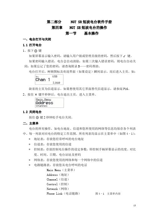
第二部分NGT SR短波电台软件手册第四章NGT SR短波电台的操作第一节基本操作一、电台打开与关闭1.1 打开电台1、按下键如果屏幕显示输入密码,请输入用户级或管理员级的密码,然后按下键。
如果密码输入错误,电台会自动清除;如果三次输入错误密码,则电台自动关闭;如果忘记了您的密码,请查询附录B——密码帮助。
电台打开后,柯顿图标及欢迎界面(如果设定)瞬间显示,而后进入主页,如:缺省的主页为信道显示。
如果想使用其它界面替代信道显示,请参阅P16。
2、按住键半秒钟后,电台退出主页,进入主菜单。
1.2 关闭电台按住键2秒钟松手电台关闭。
二、主菜单电台的所有操作,如电台地址、信道和您所使用的网络等信息均保存各个列表中。
每一列表对应电台的特定工作范围。
所有列表均显示在主菜单中(如图4–1):*地址表:存放您经常呼叫的电台地址*信道表:存放您使用的信道*控制表:存放控制电台操作的设定参数,即控制手柄屏幕显示的亮度、对比度、时间、日期、电台站址及密码*网络表:存放您使用的网络和每一个网络中的信道*电路链路表:存放您从电台呼叫的电话Main Menu(主菜单)Address(地址)Channel(信道)Control(控制)Network(网络)Phone Link(电话链路)图4–1 主菜单内容2.1 条目每一个列表都包含条目,地址表中的条目是经常呼叫的台站名称,例如“HOME”“WORK”;信道表中的条目是经常使用的信道,例如“信道1”、“信道2”。
您可以在除控制表外的其它各列表中添加条目。
Main Menu(主菜单) Entries(条目)Address(地址表)EMERGENCYHOMEWORKChannel(信道表) CHANNEL(信道) 1CHANNEL 2CHANNEL 3Control(控制表) Address(自身ID地址)Audio Volume(音频音量)Auto Resume Mode(自动回复模式)Etc…(其它)Network(网络表) Network A(网络A)Network B(网络B)Phone Link(电话链路) LINK 1LINK 2 图 4–2 条目示图2.2 设置每个条目都可以设置一个或多个参数,例如在信道表中的条目是您经常使用的信道,并且每个条目都有接收频率、发射频率及信道的工作方式。
sdrconsole 使用方法
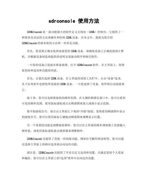
sdrconsole 使用方法SDRConsole是一款功能强大的软件定义无线电(SDR)控制台,它提供了一种简单而灵活的方法来操作和控制SDR设备。
在本文中,我将为您介绍SDRConsole的基本使用方法和一些常见功能。
首先,您需要正确安装和连接您的SDR设备。
请确保设备已正确连接到计算机,并根据设备制造商提供的说明安装驱动程序和相关软件。
一旦您的设备已连接并准备就绪,打开SDRConsole软件。
在主界面上,您将看到各种选项和功能的列表。
首先,让我们选择SDR设备。
在主界面的顶部工具栏中,点击“设备”选项。
从下拉列表中选择您所连接的SDR设备。
一旦您选择了设备,软件将自动连接到它。
接下来,您可以选择要接收的频率范围。
在左侧的频谱仪窗口中,您可以看到可见的频率范围。
使用鼠标滚轮或点击频谱图来放大或缩小显示范围。
要开始接收信号,请点击主界面左下角的“开始”按钮。
您将看到频谱图中显示的接收信号。
您可以使用鼠标左键拖动频谱图来调整显示位置。
另一个重要的功能是调整接收频率。
您可以在主界面的频率调谐器上直接输入频率值,或使用鼠标滚轮滚动调谐器来调整频率。
SDRConsole还提供了其他一些高级功能,例如信号解码和录制等。
您可以通过选择主界面上的相应选项来访问这些功能。
请注意,SDRConsole还提供了许多自定义选项和设置,以满足您的个人需求和偏好。
您可以在主界面上的“选项”菜单中访问这些设置。
总的来说,SDRConsole是一款功能强大且易于使用的SDR控制台软件。
通过按照上述步骤连接和操作SDR设备,您将能够开始接收和探索各种无线电信号。
希望本文对您理解SDRConsole的使用方法有所帮助。
如果您有任何问题或需要进一步的帮助,请随时向我提问。
mcHF SDR QRP中文操作手册 V1.0 219.18
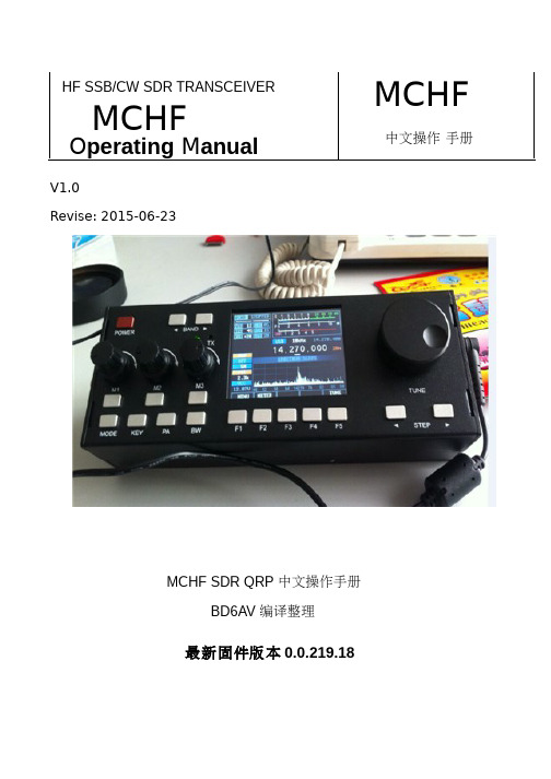
MCHF SDR QRP 中文操作手册
BD6AV 编译
2
整机设计指标参数:
基本参数: 频率范围: 发射: 工作模式: CW(A1A) AM(A3E) 最小频率步进: 天线阻抗: 工作温度范围: 频率稳定度: 工作电压: 工作电流: 50Ω -10℃---+60℃ ±1.5ppm @ 开机 5 分钟,-10℃~+60℃(标配) 9~15V DC 接收:410MA------440MA(最大显示亮度), 最小的LCD亮度可以降低40-60MA 硬件改进后降50%---80%,关机后约60MA 功放驱动级改进后3-5MA 发射:3A(FULL) 1.5A(5W) 整机尺寸: 发射机参数: 发射频段: 发射功率: 调制方式: 80,60,40,30,20,17,15,12和10米业余波段 标称5W(@13.8V),15W(@13.8V FULL) SSB 软件平衡调制 190x69x45 毫米 宽X高X厚 (不包括旋钮、ANT等突出突出物) 1Hz 接收: 2.5---30MH2–旋转编码器,M2 旋钮通常是用来调整射频增益 RFG 的,但其功能可以按 M2 键而改变,使用旋钮可调 整接收机 DSP 降噪器强度。在菜单模式,它是用来选择要调整的项目。而在正常(非菜单)状态下,按 M2 按键的时候,在接收模式时旋钮功能是调整 DSP 降噪器强度的。
MOOE 键
这个按键是用来选择收发信机的操作模式,按压这个按键将连续在 USB LSB CW-U AM 循环转换可用的模 式。但此按键在当菜单项“LSB / USB 汽车选择“启用,长按此键,将在普通转换模式和“LSB / USB 自动选择 “模式间转换,当“LSB / USB 自动选择“启用,它使电台根据频率自动选择 USB 或是 LSB(例如 USB 不会选 择低于 10 兆赫),如果要选择 CW 或是 AM 模式,长按 MOOE 键,回到普通模式,又可手动切换工作模式 了。
三晶体短波收音机手册说明书
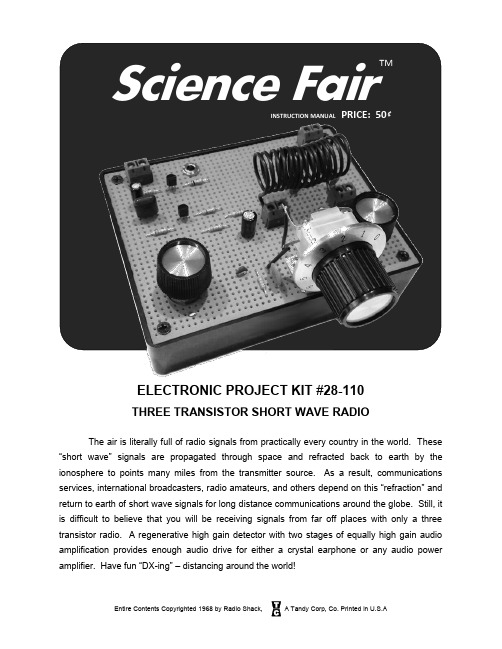
Science FairINSTRUCTION MANUAL PRICE: 50 ₵ELECTRONIC PROJECT KIT #28-110THREE TRANSISTOR SHORT WAVE RADIOThe air is literally full of radio signals from practically every country in the world. These “short wave” signals are propagated through space and refracted back to earth by the ionosphere to points many miles from the transmitter source. As a result, communications services, international broadcasters, radio amateurs, and others depend on this “refraction” and return to earth of short wave signals for long distance communications around the globe. Still, it is difficult to believe that you will be receiving signals from far off places with only a three transistor radio. A regenerative high gain detector with two stages of equally high gain audio amplification provides enough audio drive for either a crystal earphone or any audio power amplifier. Have fun “DX-ing” – distancing around the world!FIG. 1 – PICTORIAL DIAGRAM TOP VIEW 9V BatteryANT GNDPARTS LISTQuantity Identification Desc Quantity Identification Desc1 Transistor NPN (2N3904) Q1 1 .047uF Multilayer Capacitor C82 Transistor PNP (2N3906) Q2, Q3 1 .1uF Mylar Capacitor C92 33K Resistor 1/4W 5% R1, R5 1 10uF Electrolytic Capacitor C111 1K Resistor 1/4W 5% R3 1 47uF Electrolytic Capacitor C71 100K Resistor 1/4W 5% R4 1 500 Ohm Potentiometer R21 2.2K Resistor 1/4W 5% R6 1 100K Ohm Potentiometer R71 2.7K Resistor 1/4W 5% R12 1 140pF Variable Capacitor C51 22K Resistor 1/4W 5% R9 4 2-Position Screw Terminal1 47K Resistor 1/4W 5% R10 1 Crystal Earphone1 12K Resistor 1/4W 5% R8 1 9V Battery Clip1 10K Resistor 1/4W 5% R11 1 Mounting Hardware2 .01uF Disk Ceramic Capacitor C1, C6 1 Knobs (3)2 47pF Disk Ceramic Capacitor C2, C3 1 Bracket1 15pF Disk Ceramic Capacitor C4 1 WireRECOMMENDED SUPPLIER LISTJoe Knows Electronics, Amplified Parts, Mouser, Digikey, STEP-BY-STEP WIRING AND ASSEMBLY DIRECTIONSBe sure to carefully follow all the directions. Do one step at a time and then check off the step in the box provided. Before beginning, read over the enclosed page labeled “Construction Hints”.The step by step instructions indicate a soldering requirement; however, these connections can be made by firmly twisting joining wires together. If the connection is secure the circuit will work for temporary or testing purposes. If you wish a more permanent circuit, it is always best to secure these connections by soldering. Before soldering, read the instructions in “Construction Hints”.1. ( ) Check the parts list to see that everything listed is included. Check each step as you progress ( ).2. ( ) Place the pictorial diagram near the perfboard chassis so that the pictorial can be used as a guide for exact placement of parts. The gray lines in the pictorial diagram indicate components and wires which are mounted under the circuit board. The solid lines indicate components and wires mounted on top of the circuit board.3. ( ) Slightly enlarge the perfboard holes so that terminal strips T1 through T4 fit snugly in the perfboard as shown in Fig. 1 so that they face toward the back of the radio.4. ( ) Slightly enlarge the holes for the tuning control bracket to accommodate the 4-40 X 3/8” screws. Mount the tuning control bracket as shown in the pictorialdiagram Fig 1 using the two screws and two 4-40 nuts.Mount the 140pF variable capacitor C5 as shown below using the short black screws. Thread the shaft extension on the variable capacitor and tighten.5. ( ) Mount potentiometer R2 orientating the lugs as shown in the pictorial diagram Fig 1. Fasten in place with the nut and washer provided.6. ( ) Mount potentiometer R7 orientating the lugs as shown in the pictorial diagram Fig 1. Fasten in place with the nut and washer provided.7. ( ) Mount the earphone jack J1 orientating the lugs as shown in the pictorial diagram Fig 1. Fasten in place with the nut provided.8. ( ) Remove all of the insulation from a 3” piece of wire. Connect one end to the Antenna Ground pin of the screw terminal T2. Do not solder yet. Solder the other end to the potentiometer R2 lug C and solder.9. ( ) Remove 2” o f insulation from one end of a 4-1/2” piece of wire and ¼” insulation from the other end. Solder the long stripped end to the 9V battery connector (+) pin of terminal T1. Connect the other end to the potentiometer R7 lug C. Do not solder yet.10. ( ) Insert the 2.2K resistor R6 into the perfboard and bend the leads out slightly to keep the resistor in place.11. ( ) Remove 1-1/2” o f insulation from one end of a 3” piece of wire and ¼” insulation from the other end. Solder the bare short end to the 9V battery (-) pin of terminal T1. Connect the long stripped end to the resistor R6 as shown in Fig 1. Do not solder yet.12. ( ) Bend down the earphone jack J1 terminal nearest the wire from the 9V battery (-) terminal and solder as shown in Fig 1.13. ( ) Remove ¼” insulation from each end of a 4”piece of wire. Solder one end to the Antenna Ground terminal. Connect the other end to R6 as shown in Fig 1. Do not solder yet.14. ( ) Remove 1-1/2” insulation from one end of a 2-1/2” piece of wire and ¼” insulation from the other end. Insert the long bare end of the wire into the perfboard near capacitor C6 as shown in Fig 1 and solder the short bare end to the middle lead of the variable capacitor C5. Solder the other end to both pins of the coil terminal block T3 as shown in Fig 1.15. ( ) Remove 2-3/4” insulation from one end of a 4” piece of wire and ¼” insul ation from the other end. Insert the long bare end of the wire into the perfboard above and to the right of capacitor C6 as shown in Fig 1 and solder the short bare end to the top lead of the variable capacitor C5. Solder the other end to both pins of the coil terminal block T4 as shown in Fig 1.16. ( ) Insert the 2.7K resistor R12 into the perfboard. Solder one end to the bare wire from the 9V battery (+) terminal as shown in Fig 1.17. ( ) Insert the 10uF electrolytic capacitor C11 into the perfboard so that the POSITIVE capacitor lead is closest to the bare wire from the 9V battery (+) terminal as shown in Fig 1 and solder. IMPORTANT: Most electrolytic capacitors only mark the NEGATIVE lead with a band or arrow. The positive lead usually does not have a marking. Make sure you solder the correct lead in this step.18. ( ) Insert the Mylar capacitor C9 into the perfboard. Solder one end to the bare wire from the 9V battery (+) terminal as shown in Fig 1. Mylar capacitors do not have a polarity so it does not matter which direction the capacitor is inserted into the perfboard.19. ( ) Insert the 12K resistor R8 into the perfboard. Solder one end to the bare wire from the 9V battery (+) terminal as shown in Fig 1.20. ( ) Insert the 10K resistor R11 into the perfboard. Solder one end to the bare wire from the 9V battery (-) terminal as shown in Fig 1. Solder the other end to the earphone jack J1 as shown in Fig 1.21. ( ) Insert the 47K resistor R10 into the perfboard. Solder one end to the bare wire from the 9V battery (-) terminal as shown in Fig 1.22. ( ) Insert the 22K resistor R9 into the perfboard. Solder one end to the 47K resistor R10 as shown in Fig 1.23. ( ) Insert the 47uF electrolytic capacitor C7 into the perfboard so that the NEGATIVE end is closest to the 2.2K resistor R6. Connect the POSITIVE lead of C7 to resistor R6 as shown in Fig 1 and solder all leads and wires together.24. ( ) Bend the leads of PNP transistor Q3 as shown and insert into the perfboard.Make sure the flat side of the transistor faces toward the front of the radio as shown in Fig 1. Solder the emitter lead to resistor R12 and capacitor C11. Solder the collector lead to resistor R11. Solder the base lead to capacitor C9.25. ( ) Bend the leads of PNP transistor Q2 as shown in step 24 and insert into the perfboard. Make sure the flat side of the transistor faces toward the front of the radio as shown in Fig 1. Solder the emitter lead to the bare wire from the 9V battery (+) terminal using a short piece of bare wire. Solder the collector lead to resistors R9 and R10, and capacitor C9 as indicated in Fig 1. Solder the base lead to R8 and R9 as indicated in Fig 1.26. ( ) Strip ¼” of insulation from each end of a 1” piece of wire. Solder one end to resistor R9 and the other end to potentiometer R7 lug A.27. ( ) Bend down lug B of potentiometer R7 until it is flat against the perfboard.28. ( ) Insert the .047uF MLC capacitor C8 into the perfboard as close as possible to potentiometer R7 lug B and solder C8 to lug B as shown in Fig 1. MLC capacitors do not have a polarity so it does not matter which direction the capacitor is inserted into the perfboard.29. ( ) Strip ¼” of insulation from each end of a 1” piece of wire. Solder one end to the positive lead of electrolytic capacitor C7. Connect the other end to potentiometer R7 lug C. Do not solder yet.30. ( ) Insert the 33K resistor R5 into the perfboard and bend the leads out slightly to keep the resistor in place.31. ( ) Insert the .01uF disk capacitor C6 into the perfboard and bend the leads out slightly to keep the capacitor in place. Disk capacitors do not have a polarity so it does not matter which direction the capacitor is inserted into the perfboard.32. ( ) Strip ¼” of insulation from each end of a 1” piece of wire. Connect one end to potentiometer R7 lug C and solder all wires to lug C. Solder the other end to resistor R5 and capacitor C6 as shown in Fig 1.33. ( ) Solder resistor R5 to capacitor C8 as shown in Fig 1.34. ( ) First solder capacitor C6 to the bare wire from variable capacitor C5 and coil terminal T3, and then solder C6 to resistor R5 as shown in Fig 1.35. ( ) The AF detector and amplifier circuit is now complete. Check that all components and wires in the AF/Detector stage have been properly soldered. Trim leftover leads flush with their solder joints.36. ( ) Insert .01uF disk capacitor C1 into the perfboard. Solder one end to the bare wire from the Antenna Ground pin of terminal strip T2 as shown in Fig 1.37. ( ) Insert 33K resistor R1 into the perfboard. Solder one end to the bare wire from the Antenna Ground pin of terminal strip T2 as shown in Fig 138. ( ) Insert 1K resistor R3 into the perfboard. Solder one end to the bare wire from the Antenna Ground pin of terminal strip T2 as shown in Fig 139. ( ) Insert 47pF capacitor C2 into the perfboard. Solder one end to the bare wire from the Antenna Ground pin of terminal strip T2 as shown in Fig 140. ( ) Strip ¼” of insulation from each end of a 1” piece of wire. Solder one end to potentiometer R2 lug A and B. Solder the other end to capacitor C2 as shown in Fig 1.41. ( ) Solder capacitor C1 to resistor R1 as shown in Fig 1.42. ( ) Solder capacitor C2 to resistor R3 as shown in Fig 1.43. ( ) Insert 15pF disk capacitor C4 into the perfboard. Solder one end to the Antenna pin of terminal strip T2. 44. ( ) Insert 100K resistor R4 into the perfboard. Solder capacitor C4 to one end of resistor R4 as shown in Fig 1.45. ( ) Bend the leads of NPN transistor Q1 as shown in step 24 and insert into the perfboard. Make sure the flat side of the transistor faces toward the back of the radio as shown in Fig 1. Solder the emitter lead to resistor R3 as shown in Fig 1. Solder the base lead to resistor R4 and R1 as shown in Fig 1. Solder the collector lead to resistors R4 as shown in Fig 1.46. ( ) Insert 47pF disk capacitor C3 into the perfboard. Solder one end to the emitter of transistor Q1. Solder the other end to the collector lead of transistor Q1.47. ( ) Strip all insulation from a 1” piece of wire. Solder one end to capacitor C3 as shown in Fig 1. Solder the other end to the bare wire from coil terminal strip T4. 48. ( ) The RF regenerative stage is now completed. Check that all components and wires in the RF stage have been properly soldered. Trim leftover leads flush with their solder joints.49. ( ) Install the small knobs on potentiometers R2 and R7 and tighten the set screws until the knobs hold firmly to the potentiometer shaft. Install the large knob on the tuning capacitor C5 and tighten the set screw until the knob holds firmly to the tuning capacitor shaft. Do not overtighten the set screws.50. ( ) Remove ¼” of insulation from both ends of a 16-1/2” piece of wire. Holding the wire as shown in the drawing below, wrap it aroun d a “AA” battery for 8 full turns. Leave at least ¼” left over for lead length.The completed coil should look like the coil in the drawing. Wrap the coil with clear tape to prevent it from springing apart. Mount the coil (L1) by inserting one end into terminal strip T3 and the other end into terminal strip T4. Tighten the terminal strip screws until the coil leads are firmly held in place.You have completed all connections, both wiring and soldering. Carefully double check the work against the pictorial diagram.OPERATIONSThis radio will work with a 10’ or 20’ piece of wire strung across the floor used as an antenna. However, for top efficiency you will need a good antenna and ground connection. Your radio reception will never be any better than your antenna system. You may use a cold water pipe for ground; however, a metal rod driven 2’ or 4’ into the ground works best. Excellent for this use is the Radio Shack ground rod (Radio Shack Cat. #15-530). Connect the wire from the ground rod to the Antenna Ground terminal of terminal strip T2. The Antenna terminal of terminal strip T2 should be connected to an outdoor antenna of the type illustrated in figure 3 (Radio Shack Cat. #278-1373), and can be as long as facilities permit. The longer the antenna you are able to construct, the better quantity of reception you will receive, especially at low frequency. If this is not practical, such makeshift antennas can be used as your television antenna, citizens band antenna, or even the metal dial stop of your telephone.Connect the read lead of the battery clip to the positive (+) terminal of the terminal strip T1 and the black lead to the negative (-) terminal of the terminal strip T1. Insert the earphone plug into the earphone jack J1. Insert a 9V transistor battery (Radio Shack Cat. #23-464 or 23-152) and you are ready to operate your radio.There are three controls on your short wave radio. The potentiometer R7 is the volume control for the audio output, the other potentiometer R2 is the regeneration control. The variable capacitor C5 is your tuning capacitor. To operate the radio, advance R7 fully clockwise, turn R2 half way clockwise. Now slowly tune the variable tuning capacitor until a station is heard. Adjust the potentiometer R2 until a maximum signal is heard. If the regeneration control R2 is advanced too far, a loud pop or squeal will be heard in the earphone. This indicated that you have gone into full regeneration and the potentiometer should be backed off slightly. It is possible to receive code (CW) in this condition. In order to hear a voice signal you need to adjust the regeneration control just prior to this oscillation condition. This point is referred to as the threshold point. If necessary reduce the volume to a comfortable listening level using the volume control R7, not the regeneration control.ADDITIONAL COIL WINDING INFORMATIONYour shortwave radio can be operated at frequencies ranging from 4.5 to about 50MHZ depending on the number of turns in the coil. A chart is given below which indicates the number of turns required for a given frequency of operation. Construct the coil as shown in the step by step instructions but with the number of turns required for the frequency desired. For the larger coils cellophane tape can be used to hold the coil together. Different frequencies or operations have better reception depending on the time of day. Included below is additional information which shows the best time to listen to the frequency that you are interested in.Frequency Coil Turns Best Reception Time 4.5-7 MHz 46 Late night6-10 MHz 25 Night often sunset9-14 MHz 15 Late afternoon-night13-20 MHz 8 Morning-afternoon19-28 MHz 5 Morning-early afternoon 26-50 MHz 2 MorningPOWER SUPPLYFor more permanent use you can completely eliminate the need for batteries with the AC-DC power supply kit #28-104. It supplies either 6 or 9 volts DC for most of the Science Fair Kits as well as most transistor radios, tape recorders, and phonographs. Complete connections are shown below.AMPLIFIER CONNECTIONSIf you wish to use a speaker with your radio it is necessary to use additional amplification. Ideal for the purpose is the Science Fair OTL Amplifier #28-106 and the Science Fair Extension Speaker #28-123. It is necessary to couple the radio to the amplifier with a dropping transformer #273-2378. The unit will probably work better in this condition if resistor R-11 is removed. Complete connections are shown below.OTL AUDIO AMPLIFIERSHORT WAVE RADIOFIG. 2 – SCHEMATIC。
IC-M802海用单边带短波电台使用说明书

1
用或关闭话音静噪功能,或调节静噪大小) 2. 当接收到信号时,“RX”字样会出现在显示窗,转动[VOL]可调节音量大小 3. 根据需要,可使用以下功能以声音清晰: ¾ 噪音消隐:按[F],再按[1 NB]可开关噪音消隐功能 (使用噪音消隐时,“NB”字样会出现
■ 接收的功能 1、静噪功能
此功能是检测音频成份的信号,和抑制不需要的信号,诸如非调制的拍频信号等,用 于提供一个安静的准备状态。
当需要接收微弱信号时,静噪应切断。按[F]键,再按(SQL)关静噪抑制功能, 当“SQL”字样显示时,表示静噪功能接通(噪音被抑止) 2、噪声抑制 此噪声抑制是降低脉冲型的噪声,诸如从发动机点火带来的噪声。 此噪声抑止可能使强信号失真,在这种情况下,应把噪声抑制切断。按[F]键,再 按(NB)按钮,以使噪声抑制功能关闭。 当“NB”字样显示时,表示噪声抑制功能接通。 3、 自动增益控制(AGC)切断功能 接收机用自动增益控制,按接收信号的强弱,来自动调整增益,以防止在强信号时 信号失真,及获得一个稳定的输出。 当接收信号微弱,而伴随着邻近的强信号噪声时,自动增益控制功能将降低接收机 的灵敏度,在此情况下,应将自动增益控制功能切断。按[F]键,再按(AGC),以使自动 增益控制功能切断。 当 AGC 字样显示时,AGC 功能开通。
2.面板介绍
2
1、 遇险报警键[DISTRESS]
按住[DISTRESS]键约 5 秒钟发送遇险呼叫
2、 DSC 切换键[DSC]
切换 DSC 值守模式和语音/E-MAIL 通信模式
3、 取消/呼叫键[CANCEL/CALL]
● 取消遇险报警或遇险重复呼叫 ● 设定 DSC 内容后,按住 1 秒开始呼叫
- 1、下载文档前请自行甄别文档内容的完整性,平台不提供额外的编辑、内容补充、找答案等附加服务。
- 2、"仅部分预览"的文档,不可在线预览部分如存在完整性等问题,可反馈申请退款(可完整预览的文档不适用该条件!)。
- 3、如文档侵犯您的权益,请联系客服反馈,我们会尽快为您处理(人工客服工作时间:9:00-18:30)。
SDR短波电台使用说明书:
频率范围RX: 0.5MHz-30MHz
发射: 所有业余无线电短波频段
收发模式SSB(J3E),CW,AM(接收), FM, 数字语音
滤波器可调范围500HZ-10KHZ
输出功率1W-13W(最大)
接收灵敏度0.11~0.89μV(RFC 50-20)
最小步进1Hz
电压范围DC9~15V
内置电池容量12.6V 2200mah
接收电流350mah
内置驻波表显示精准
内置电池携带方便
内置USB声卡可以使用电脑的SDR软件通过USB口收发,使用FT817协议,支持WSJT-X数字通讯支持ACC口控制外接70-100W功放
天线阻抗50Ω
频率稳定度±1.5PPM 开机5分钟(标准) ; ±0.5PPM 打开温补功能
最大电流3.5A
尺寸(W ×H ×D)
190mm*69mm*45mm
重量980g
配件有充电器手咪BNC转N头六角扳手2个固定架子
收听广播步骤:
接上天线,侧面开关拨到ON ,按住POWER1秒开机,按BNAD <> 选择3.X或者5.X开头频率,按MODE多次选择AM模式,
按STEP选择下标1KHZ,旋转TUNE直到收到台,关机:长按Power关机,长时间不用,侧面开关打到OFF
业余无线电对讲步骤:
接上天线,机器旁侧面开关拨到ON ,按住POWER1秒开机,按BNAD <> 选择7.X或者14.X开头频率,按MODE多次选择USB或者LSB模式,按STEP移动位数,按TUNE调数字调到7.050或者14.270,留意是否有人讲话,按PA选择5W,手咪接到Mic插口,按手咪讲话,声音越大,指示表显示越大,功率越大,如果没反应,长按几次M3 选择MIC模式,注意SWR显示,3以下效率比较低,有条件的调整天线长度最佳为SWR<=1.5,关机:长按Power关机,长时间不用,侧面开关打到OFF
3.电压低于9.9V自动关机,充电步骤,1:侧面开关打到OFF,2:充电器接上转接头接到小的供电口(Charge Only),充电器红灯亮,充满变绿灯(充电器只能给机器充电,不能接DC in工作)
频率校准:
频率调到10MHZ或者15MHZ,听到了类似对时的声音说明可以对时
按MODE选择SAM模式,右上角会显示误差的频率,如果与当前频率相差5HZ以上说明偏差较大,旋转RIT修正右上角的频率到5HZ以内即可。