HF-90E短波电台使用手册
电子流量计FMG90系列产品说明书

FMG90 SeriesElectromagnetic Flow Meter- 2 -Table of contents page 0About this operating manual (4)1Device description (5)1.1Delivery, unpacking and accessories (5)1.2Intended use (6)1.3Exclusion of liability (6)2Safety instructions (7)3Construction and function (8)4Installation of FMG90 (9)4.1Installation instructions (9)4.2Assembly (10)5Electrical connection (11)6Commissioning and measuring operation (12)6.1Commissioning (12)6.2Switching on and off (12)6.3Measuring operation (12)7Maintenance and cleaning (13)7.1Return shipment to the manufacturer (13)8Disassembly and disposal (14)9Technical data (15)9.1Characteristics FMG90 (15)9.2Materials table (16)9.3Pressure drop (16)9.4Dimensions (17)Copyright notice:The reproduction, distribution and utilization of this operating manual as well as the communication of its contents to others without express authorization is prohibited. Offenders will be held liable for the payment of damages. All rights reserved in the event of the grant of a patent, utility model or design. Technical changes reserved - 3 -About this operating manual Series FMG90- 4 -0 About this operating manual• The operating manual is aimed at specialists and semi-skilled personnel.• Before each step, read through the relevant advice carefully and keep to the specified order.•Thoroughly read and understand the information in the section "Safety instructions".If you have any problems or questions, please contact your supplier or contact us directly at:One Omega Drive, P.O. Box 4047Stamford, CT 06907-0047 Tel: (203) 359-1660 e-mail:**************Hazard signs and other symbols used:WARNING! / CAUTION! Risk of injury!This sign indicates dangers that cause personal injuries that can lead to health defects or cause considerable damage to property.CAUTION! Electric current!This sign indicates dangers which could arise from handling of electric current.CAUTION! Material damage!This sign indicates actions which could lead to possible damage to material or environmental damage.ADHERE TO OPERATING MANUAL! NOTICE!This symbol indicates important notices, tips or information. NO DOMESTIC WASTE!The device must not be disposed of together with domestic waste.Pay attention to and comply withinformation that is marked with this symbol.Follow the specified instructions and steps.Adhere to the given order.❑Check the specified points or notices.Reference to another section, document orsource. • Item.Series FMG90 Device descriptionTechnical changes reserved- 5 -1 Device descriptionThe flow meter of the FMG90 series from OMEGA ENGINEERING INC. is a magnetic inductive flow sensor for conductive liquids. The flow measurement is performed using magnetic induction and works without any moving parts.The FMG90 is used for measuring or metering water and aqueous solutions. The compact design and independence from the intake and discharge sections allows the FMG90 to be used under a variety of conditions.Versions ∗:The FMG90 is available in different nominal sizes from DN 3 to DN 25.The versions can be configured differently.Type plate:You can find the sticker of the type plate on the front of the FMG90.It contains the most important data and the connection diagram for the electrical connection (Example Fig.).1.1 Delivery, unpacking and accessoriesAll units have been carefully checked for their operational reliability before shipment.❒ Immediately after receipt, please check the outer packaging for damages or any signs ofimproper handling.❒ Report any possible damages to the forwarder and your responsible sales representative.In such a case, state a description of the defect, the type and the serial number of the device.Report any in-transit damage immediately. Damage reported at a later date shall not be recognized. Unpacking:Carefully unpack the unit to prevent any damage.Check the completeness of the delivery based on the delivery note.Scope of delivery:❒ 1x FMG90 according to the order data.❒1x Operating manual. ❒ 1x Packaging.∗ Customised versions available on request.Device descriptionSeries FMG90- 6 -IMPORTANT!Use the type plate to check if the delivered unit corresponds to your order.In particular, for devices with electrical components, check to see if the correct power supply voltage is specified.Accessories:❒ Connection cable with moulded M12x1 coupling socket. ❒ M12x1 coupling socket as component.1.2 Intended useThe magnetic inductive flow sensor FMG90 must only be used for measuring and metering liquids with a minimum conductivity of 20 μS/cm.WARNING! No safety component!The magnetic inductive flow sensor of the series FMG90 is no safety component in accordance with Directive 2006-42-EC (Machine Directive). Never use the FMG90 as a safety component.The operational safety of the device supplied is only guaranteed by intended use. The specified limits (♑ § 9 "Technical data") may under no circumstances be exceeded.Before installing the device, check that the wetted materials of the device are compatible with the media being used (♑ § 9.2 "Materials table").Measuring tube empty (or partially filled). / Conductivity too low.The green LED may blink irregularly if the measuring tube of the FMG90 is empty or partially filled or if the conductivity of the fluid being used is too low. Random pulses will be present at the output, but they do not represent an actual flow.Ensure that the measuring tube of the FMG90 is always completely filled (♑ § 4.1 "Installation instructions").Ensure that the conductivity of the fluid is at least 20 μS/cm.1.3Exclusion of liabilityWe accept no liability for any damage or malfunctions resulting from incorrect installation, inappropriate use of the device or failure to follow the instructions in this operating manual.Series FMG90 Safety instructionsTechnical changes reserved - 7 -2Safety instructionsBefore you install the FMG90, read through this operating manual carefully. If theinstructions contained within it are not followed, in particular the safety guidelines, this could result in danger for people, the environment, and the device and the system it isconnected to.The FMG90 correspond to the state-of-the-art technology. This concerns the accuracy, the operating mode and the safe operation of the device.In order to guarantee that the device operates safely, the operator must act competently and be conscious of safety issues.OMEGA ENGINEERING INC. provides support for the use of its products either personally or via relevant literature. The customer verifies that our product is fit for purpose based on our technical information. The customer performs customer- and application-specific tests to ensure that the product is suitable for the intended use. With this verification all hazards andrisks are transferred to our customers; our warranty is not valid.Qualified personnel:The personnel who are charged for the installation, operation and maintenance of the FMG90 must hold a relevant qualification. This can be based on training or relevanttuition.The personnel must be aware of this operating manual and have access to it at all times.The electrical connection should only be carried out by a fully qualified electrician. General safety instructions:In all work, the existing national regulations for accident prevention and safety in the workplace must be complied with. Any internal regulations of the operator must also becomplied with, even if these are not mentioned in this manual. Degree of protection according to EN 60529:Please ensure that the ambient conditions at the site of use does not exceed therequirements for the stated protection rating ( § 9 "Technical data"). Prevent freezing of the medium in the device with appropriate measures.Only use the FMG90 if it is in perfect condition. Damaged or faulty devices must be checked without delay and, if necessary, replaced.When fitting, connecting and removing use only suitable appropriate tools.Do not remove or obliterate type plates or other markings on the device, as otherwise thewarranty is rendered null and void. Special safety instructions: Crystallizing liquids:Liquids which crystallize when dried out can cause a malfunction of the FMG90. Make sure that the FMG90 is not run dry.Prevent the crystallization of the fluid in the device by taking appropriate measures.Further warnings that are specifically relevant to individual operating procedures or activities can be found at the beginning of the relevant sections of this operating manual.Construction and function Series FMG90- 8 -3 Construction and functionComponents:① Housing:The Housing consists of plastic and has the IP65 degree of protection.② Electrical connection:The electrical connection is made via 4-pin plug M12x1.③ Operation / flow indicator LED.④ Type plate with flow direction (marking)⑤ Process connection:The process connections are available in different sizes.Construction:The measuring tube with its earthing sleeves and electrodes passes through the housing and forms the external process connection of the FMG90.A magnetic field for the measurement process is generated inside the housing, which also contains the sensor and signal conditioning circuitry.The two stainless steel electrodes are located in the middle of the measuring tube between the earthing sleeves.The FMG90 does not need any moving parts to make measurements. The inside of the measuring tube is completely open, allowing the fluid to flow unhindered through the measuring tube.Function:The magnetic inductive flow sensor functions according to the induction principle. A DCvoltage is generated by the movement of a conductor in a magnetic field:The measuring tube of the FMG90 is located in a magnetic field (B).An electrically conductive medium (V) flows through the measuring tube. The positive and negative charge carriers are oppositely deflected.A voltage (U) is generated at right angles to the magnetic field, which is picked up by the two electrodes.Thereby, the induced voltage is proportional to the average flow velocity of the liquid. The electronics of the FMG90 converts the induced voltage into a flow-proportional frequency signal.Series FMG90 Installation of FMG90Technical changes reserved - 9 -4 Installation of FMG90Before installing, check that❒ the wetted materials of the device are suitable for the media being used ( § 9.2"Materials table").❒ the equipment is switched off and is in a safe and de-energised state. ❒ the equipment is depressurised and has cooled down.SUITABLE TOOLS:Use only suitable tools of the correct size.4.1 Installation instructionsCAUTION! Risk of malfunction due to external magnetic fields! Magnetic fields close to the device can cause malfunctions andshould be avoided.Ensure that no external magnetic fields are present at theinstallation site of the FMG90.•The FMG90 can always be installed anywhere along the pipeline. However, straight sections of piping are preferable.Installation of FMG90Series FMG90- 10 -• Installation can occur in horizontal and vertical pipes. The flow sensor is only suitable for application in completely filled pipe systems.•As a matter of principle magnetic inductive flow sensors are widely independent from the flow profile. An inlet section is not absolutely necessary.To reach a most highly accuracy of the measurement, you should use straight inlet and outlet sections according to the nominal width (DN). The inlet section has to be at least 10 x DN; the outlet section 5 x DN in order to achieve the specified accuracy. •The inlet and outlet sections and the gaskets must have the same or a slightly larger inside diameter than the measuring tube in order to achieve the specified accuracy.•If two or more FMG90 devices are used side by side,maintain a separation of at least 2.5 cm between adjacent devices.If adjacent devices are too close together, operation of both devices may be impaired due to mutual interference.4.2 AssemblyThe FMG90 is installed directly into the pipeline. The compact design and light weight of the unit make wall-mounting unnecessary.IMPORTANT NOTICES:• Only use suitable gaskets for installation.• Observe the flow direction indicated on the type plate. • Observe the mounting dimensions (♑ § 9.4 "Dimensions").Select an appropriate location for installation (♑ § 4.1"Installation instructions").To ensure the best possible measuring accuracy, a vertical installation position with increasing flow is preferable (no collecting of dirt deposits). Install the appropriate screwed connections at the installationlocation. Insert the FMG90 together with the gaskets.Screw the union nuts of the screwed connection onto theprocess connections of the FMG90.CAUTION! Material damage!Maximum torque 5 Nm.While tightening, counter the FMG90 only by hand!If you use an open-end or a pipe wrench, the FMG90 can be damaged.Tighten both union nuts with a maximum torque of 5 Nm.Series FMG90 Electrical connectionTechnical changes reserved - 11 -5 Electrical connectionThe electrical connection of the FMG90 is via the 4-pin plug M12x1 at the top of the housing. The corresponding connection cables with moulded coupling socket are available in various lengths included in the range of OMEGA ENGINEERING INC. accessories.CAUTION! Electric current!The electrical connection should only be carried out by a fully qualified electrician. De-energize the electrical system before connecting the FMG90.Connection and wiring:Screw the coupling socket of the connection cable to the plug of the FMG90. Tighten the knurled nut of the coupling socket with a maximum torque of 1 Nm. Connect the connection cables according to the following wiring diagrams. Pin assignment:Pin 1: +U B Pin 3: GNDPin 2 / 4: Frequency output NPN/PNPPin configuration with NPN frequency output:PNP frequency output:Pull-up- / pull-down-resistors R.We recommend using resistors of ~1 k Ω (12V) respectively ~2.2 k Ω (24V) and 0.25 W for the pull-up / pull-down wiring. Please note that the maximum signal current of 25 mA will not be exceeded.Commissioning and measuring operation Series FMG90- 12 -6 Commissioning and measuring operationBefore switching on the FMG90 for the first time, please follow the instructions in the following section.6.1 CommissioningCheck that❒ the FMG90 has been installed correctly and that all screw connections are sealed. ❒ the electrical wiring has been connected properly. ❒ the measuring system is vented by flushing.6.2 Switching on and offThe FMG90 has no switch and cannot be switched on or off on its own. Switching on and off is carried out by the applied supply voltage. Switch on the supply voltage.The red LED lights up permanently. The FMG90 is ready for use and goes into measuring operation.6.3 Measuring operationIn the measuring mode, the red LED is permanently lit and indicates that the FMG90 is operational.The green LED flashes proportional to the measured flow.The human eye cannot detect the flashing any longer from a frequency of ~30 … 40 Hz.In that case the green LED seems to be lit permanently.Frequency output:The frequency output provides a flow-proportional PNP/NPN square wave signal. The frequency changes according to the flow ( Fig.).Series FMG90 Maintenance and cleaningTechnical changes reserved - 13 -7 Maintenance and cleaningMaintenance:The FMG90 is maintenance-free and cannot be repaired by the user. In case of a defect, the device must be replaced or sent back the manufacturer for repair.CAUTION! Material damage!When opening the device, critical parts or components can be damage. Never open the device and perform any repair yourself.Cleaning:Clean the FMG90 with a dry or slightly damp lint-free cloth. Do not use sharp objects or aggressive agents for cleaning.7.1 Return shipment to the manufacturerDue to legal requirements placed on environmental protection and occupational safety and health and to maintain the health and safety of our employees, all units returned to OMEGA ENGINEERING INC. for repair must be free of toxins and hazardous substances. That also applies to cavities in the devices. If necessary, the customer must neutralise or purge the unit before return to OMEGA ENGINEERING INC..Costs incurred due to inadequate cleaning of the device and possible costs for disposal and/or personal injuries will be billed to the operating company.WARNING! Risk of injury due to insufficient cleaning!The operating company is responsible for all damages and harm of any kind, in particular physical injuries (e.g. caustic burns or toxic contaminations), decontamination measures, disposal etc. that can be attributed to insufficient cleaning of the measuring instrument. Comply with the instructions below before returning the unit.The following measures must be taken before you send the unit to OMEGA ENGINEERING INC. for repair:Clean the device thoroughly. This is of extreme importance if the medium is hazardous tohealth, i.e. caustic, toxic, carcinogenic or radioactive etc.Remove all residues of the media and pay special attention to sealing grooves and slits. Attach a note describing the malfunction, state the application field and thechemical/physical properties of the media.Please specify a point of contact in case our service department has any questions.Disassembly and disposal Series FMG90- 14 -8 Disassembly and disposalCAUTION! Risk of injury!Never remove the device from a plant in operation.Make sure that the plant is shut down professionally.Before disassembly:Prior to disassembly, ensure that❒ the equipment is switched off and is in a safe and de-energised state. ❒ the equipment is depressurised and has cooled down.Disassembly:Remove the electrical connectors. Remove the FMG90 using suitable tools.Disposal:NO HOUSEHOLD WASTE!The FMG90 consists of various different materials. It must not be disposed of with household waste.Take the FMG90 to your local recycling plantorsend the FMG90 back to your supplier or toOMEGA ENGINEERING INC..Series FMG90 Technical dataTechnical changes reserved - 15 -9 Technical dataThe technical data of customised versions may differ from the data in these instructions. Please observe the information specified on the type plate.9.1 Characteristics FMG90** other pulse rate / resolution on request.optional: Output signal with lower frequency, designed specifically for connection to digital PLC inputs.Technical data Series FMG90- 16 -9.2 Materials table9.3 Pressure dropSeries FMG90 Technical dataTechnical changes reserved- 17 -9.4 DimensionsFMG9… DN 3 / DN 8 / DN 15 / DN 20:FMG96 DN 25:For your notes Series FMG90 For your notes- 18 -Series FMG90Technical changes reserved - 19 -Series FMG90M-5649/0317 - 20 -。
短波收音机收听手册

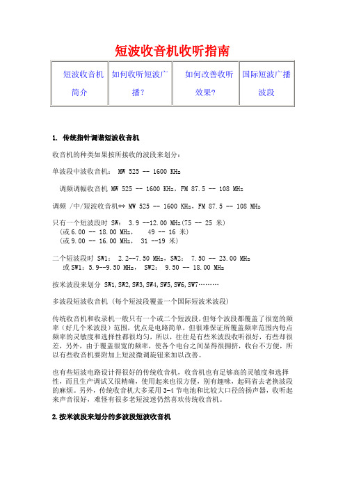
短波收音机收听手册当下市面上的全波段(World Band)数调短波收音机调谐的频率跨度很大,典型的调谐范围从150KHz到30000KHz,几乎囊括长波、中波、短波的全部波段。
根据国际无线电联盟的协定,无线电频率被划分并供应给不同用途的使用者。
虽然偶有犯规者,但绝大多数台(站)都恪守许可使用的频率。
150KHz及以下。
这个频率的无线电波不能通过电离层传播,却可以很好地穿透海洋的深处,因此,在这个频率下可以发现许多做潜艇通讯的军事电台。
德国、英国、日本、瑞士和白俄罗斯等国的标准时间标准频率发播台的发射频率都在20-80khz之间,普通收音机是根本接收不到的。
150到540KHz。
这是BCLer和Dxer通称的长波段。
在收音机里能听到的大多数信号是一些信标台不断重复摩尔斯(Morse)电码呼号。
长波广播从153KHz 启用,大功率的长波广播以俄罗斯和东欧国家为甚,非洲及澳大利亚、蒙古和前苏联加盟共和国等部分亚太地区国家也有长波广播,但我国广播并未染指这一领地。
法国标准时间标准频率发播台使用162khz。
在长波的高端,可以接收到一些RTTY(无线电传)信号。
海洋气象和安全广播,如无线电爱好者熟知的VTEX (航行警告自动通信系统)就是在512KHz发射。
这个波段的最好接收时间是秋冬季的夜晚。
我国的北方地区容易接收到独联体国家的长波广播。
540KHz到1710KHz。
这是中波广播。
亚洲和中南美洲地区的中波起始段被划为530KHz。
传统收音机的中波到1600KHz结束,而实际意义上的中波广播波段却在1710KHz结束。
从1610到1710KHz是新的中波扩展领域,从1997年开始,不断有电台在这一波段上播音,给无线电爱好者提供了精彩的DX(远程无线电接收活动)契机。
但1700khz以上频率入驻的中波广播电台寥寥无几,据WRTH(《世界广播电视手册》)最新记录,全球仅有两家广播电台在1700khz——1710khz发声,澳大利亚转播当地赛马和服务偏远地区土著民的广播电台就使用1701KHz,阿根廷RadioPalacio-AM1710电台使用1710KHz,发射功率均在1KW以下,远程接收极具挑战性。
F系列无线数传电台使用说明V3070826
收发功能
单发
单发
单收
收发
收发
收发
收发
收发
收发
发射功率
5W
500m W
——
500m W
5W
25W
5W
100m W 10m W
灵敏度
——
——
≤0.25 ≤0.25
≤0.25
≤0.25
≤0.25 ≤0.25
≤1
发射电流 ≤1.3A
≤0.3A
——
≤0.3A
≤1.3A
≤7A
≤1.3A ≤0.3A ≤0.1A
待机电流
TTL-RS485 连线中间颜色为 黄标有 TTL 的一边接电台
TTL-RS232 连线 中 间 颜 色 为 红。标有 TTL 的一边接电台
D、电台数据格式:电台的数据格式有两种一种是一个起始位、八个数据位、一个停止位。另一 种为一个起始位、九个数据位、一个停止位。其中第九位的用途随着上位机格式的不同而不同。上 位机的数据格式及第九位的用途见下表:
北京捷麦通信器材有限公司 电传:(010)63331035--37
8
地址:北京市丰台区菜户营东街甲 88 号鹏润家园静苑 B 座 2504 网址:
F21 系列无线数传电台使用说明 V3.0070401
None
Even无第 9 位
≤85mA ≤85mA
≤85mA
≤85mA
≤85mA ≤85mA ≤30mA
省电待机
≤2.5mA ≤2.5mA
≤2.5mA
≤1.2mA ≤1.2mA ≤0.8mA
工作频段
228.000MHz-232.000MHz
433.000MHz
信道间隔
IC短波全频段电台使用说明

电台前面板:
二
IC-718日常使用
调步进
调步进:
1、按下TS按键,这时会显示目前选择的步进。然后长按TS按键1秒。 2、旋转主旋钮选择步进。 3、按下TS按键,退出步进调节。
□电台处在发射模式。
接收的信号杂音大的可能原因: 3 □选择的操作模式不正确;
□ SHIFT,NOISE,PREAMP等功能打开; □天线未连接好,接触不良。
谢谢观看!
携手共进,齐创精品工程
Thank You
世界触手可及
电台前面板:
二
IC-718日常使用
调频发射
开机调频率:
1、按PWR键开机,此时显示屏应有显示。 2、调主调节旋钮调整频率,顺时针频率增大,逆时针频率减小。 3、按TUNER键,显示屏TUNE消失后,按手咪PTT键即可发话。
电台前面板:
二
IC-718日常使用
调模式
开机调模式:
1、按PWR键开机,此时显示屏应有显示。
电台前面板:
三 IC-718面板介绍
三
面板介绍
三
面板介绍
四 常见问题解决
四
常见问题解决
按下PWR键后无电源显示的可能原因: 1 □电源没有打开;
□保险丝烧掉,检查电源,更换电源保险丝;
□ 电源连接线未连接好,重新检查接好连接线。
2
开机后没有声音的可能原因: □音量太小,调AF旋钮;
□静噪水平太高,调RF/SQL旋钮至中立位置;
一
使用注意
电击提醒
永远不要在开机时用金属、电线或其它物体接触电台内部 或接触后面板,这可能会导致电击。
第四章NGT SR短波电台的操作zsp
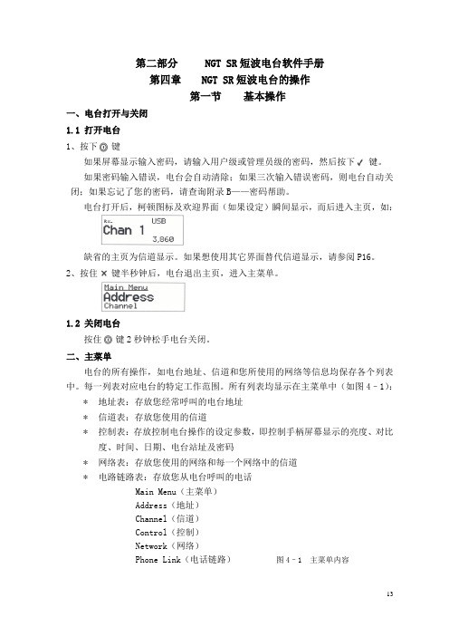
第二部分NGT SR短波电台软件手册第四章NGT SR短波电台的操作第一节基本操作一、电台打开与关闭1.1 打开电台1、按下键如果屏幕显示输入密码,请输入用户级或管理员级的密码,然后按下键。
如果密码输入错误,电台会自动清除;如果三次输入错误密码,则电台自动关闭;如果忘记了您的密码,请查询附录B——密码帮助。
电台打开后,柯顿图标及欢迎界面(如果设定)瞬间显示,而后进入主页,如:缺省的主页为信道显示。
如果想使用其它界面替代信道显示,请参阅P16。
2、按住键半秒钟后,电台退出主页,进入主菜单。
1.2 关闭电台按住键2秒钟松手电台关闭。
二、主菜单电台的所有操作,如电台地址、信道和您所使用的网络等信息均保存各个列表中。
每一列表对应电台的特定工作范围。
所有列表均显示在主菜单中(如图4–1):*地址表:存放您经常呼叫的电台地址*信道表:存放您使用的信道*控制表:存放控制电台操作的设定参数,即控制手柄屏幕显示的亮度、对比度、时间、日期、电台站址及密码*网络表:存放您使用的网络和每一个网络中的信道*电路链路表:存放您从电台呼叫的电话Main Menu(主菜单)Address(地址)Channel(信道)Control(控制)Network(网络)Phone Link(电话链路)图4–1 主菜单内容2.1 条目每一个列表都包含条目,地址表中的条目是经常呼叫的台站名称,例如“HOME”“WORK”;信道表中的条目是经常使用的信道,例如“信道1”、“信道2”。
您可以在除控制表外的其它各列表中添加条目。
Main Menu(主菜单) Entries(条目)Address(地址表)EMERGENCYHOMEWORKChannel(信道表) CHANNEL(信道) 1CHANNEL 2CHANNEL 3Control(控制表) Address(自身ID地址)Audio Volume(音频音量)Auto Resume Mode(自动回复模式)Etc…(其它)Network(网络表) Network A(网络A)Network B(网络B)Phone Link(电话链路) LINK 1LINK 2 图 4–2 条目示图2.2 设置每个条目都可以设置一个或多个参数,例如在信道表中的条目是您经常使用的信道,并且每个条目都有接收频率、发射频率及信道的工作方式。
短波收音机收听指南
短波收音机收听指南1. 传统指针调谐短波收音机收音机的种类如果按所接收的波段来划分:单波段中波收音机: MW 525 -- 1600 KHz调频调幅收音机 MW 525 -- 1600 KHz,FM 87.5 -- 108 MHz调频 /中/短波收音机** MW 525 -- 1600 KHz,FM 87.5 -- 108 MHz只有一个短波段时 SW: 3.9 --12.00 MHz(75 -- 25 米)(或6.00 -- 18.00 MHz, 49 -- 16 米)(或9.00 -- 16.00 MHz, 31 --19 米)二个短波段时 SW1: 2.2--7.50 MHz,SW2: 7.50 -- 23.00 MHz或SW1:5.9--9.50 MHz, SW2: 9.50 -- 18.00 MHz按米波段来划分SW1,SW2,SW3,SW4,SW5,SW6,SW7………多波段短波收音机 (每个短波段覆盖一个国际短波米波段)传统收音机和收录机一般只有一个或二个短波段,但每个波段都覆盖了很宽的频率(好几个米波段)范围,优点是电路简单,但很难保证所覆盖频率范围内每点频率的灵敏度和选择性都很均匀,所以,往往是有些米波段收听很好,有些却很差,另外,由于覆盖很宽的频率,使各个电台之间显得很拥挤,收台不方便,所以有些收音机要附加上短波微调旋钮来加以改善。
也有些短波电路设计得很好的传统收音机,收音机也有足够高的灵敏度和选择性,而且生产调试又很精确,使用起来也很方便,别有趣味,起码省去老换波段的麻烦。
另外,传统收音机大多采用3-4节电池和比较大口径的扬声器,收听起来声音很好,难怪有很多老短波迷仍然喜欢传统收音机。
2.按米波段来划分的多波段短波收音机现代的短波收音机,往往分为6-10个短波段,每个短波只覆盖一个米波段(请参考下文国际广播米波段表),对于设计良好的此类短波收音机,灵敏度和选择性比较容易得到保证,而且按米波段来划分短波,电台之间的间隔好象被展阔了,收短波象收听中波一样方便,尤其是对于电台最密集的16,19,25,31米波段,优点更突出。
无线电台调谐说明书

调谐至一个无线电台自动调谐1.按主机上的TUNER 几次以选择"AM"或"FM"。
2.按 TUNING MODE ,使显示屏上的 "AUTO"指示灯亮起。
3.按 TUNING 开始自动调谐。
找到一个电台后搜索自动停止。
调到一个无线电台后,显示屏上的 "TUNED" 指示灯亮起。
调到一个 FM 无线电台时,"FM STEREO" 指示灯亮起。
"TUNED " 灯熄灭时不会输出任何声音。
FM 无线电台的信号微弱时:取决于建筑物结构和环境条件,无线电波可能会很微弱。
在此情况下,执行下一部分"手动调谐"中所说明的手动调谐程序,以便手动选择所需电台。
手动调谐1.按主机上的TUNER 几次以选择"AM"或"FM"。
AM/FM 接收详情2.按 TUNING MODE,使显示屏上的 "AUTO" 指示灯熄灭。
3.按 TUNING,选择想收听的无线电台。
每按一下按钮,频率改变 1 个步长。
按住按钮时频率会持续变化,松开按钮后停止。
调台时注意显示屏。
要返回至自动调谐:在主机上再次按TUNING MODE。
本机将自动调谐到无线电台。
一般情况下应显示"AUTO"。
直接调谐到频率用于直接输入您要收听的无线电台的频率。
1.按遥控器上的TUNER几次以选择"AM"或"FM"。
2.按 D.TUN。
3.使用数字按钮,在8秒钟内输入无线电台的频率。
例如,要调到 87.5 (FM),按 8、7、5,或 8、7、5、0。
如果输入的数字错误,请按D.TUN 并输入正确值。
注册一个AM/FM 无线电台可以记录最多 40 个您最喜欢的 AM/FM 无线电台。
提前记录无线电台让您能够直接调到喜欢的电台。
蛙鸣套件说明书V5.1

错。
套件之家
磁环线圈的绕制 下图是磁环线圈的匝数判断方法,仅用于指导辨认线圈匝数:
之家 此线圈匝数为 12 圈,同时注意线圈要均匀分布在磁环的周围。 件 ba IC的识别 套 s.tao 8 脚直插与14 脚直插IC的管脚排列 mykit 晶体管的识别
D1,D3,D5,D6
1N4148
D2,D4
1N4001
Q1
2SK30A
Q2,Q4,Q6
8050
Q3
8550
Q5
套件之家
D882
对应为 ECB
集成电路
U1
78L08(TO92)
U2
NE602(DIP8)
配 IC 插座
U3
LM386(DIP8)
1K
R1
1
3
1
3
+ CP8
10u /25V
2
R10
R12
R4
1K
10K
1K
1
3
Q4 8050
R13
18K C20 0.1u
J3 2 3 4 5 1
KEY
C13 0.022u
C16 470p
R6 18K C22 0.047u C19 0.022u R11 1K
1N4001
D882
L3 FT37-43磁环(黑色) 0.51mm线径11匝
套件之家
元件清单
1/4W 固定电阻
R1,R4,R10,R11
1K
R2
1M
R3,R12
10K
R5
100K
R6,R13 R7,R8
18K 10 欧
- 1、下载文档前请自行甄别文档内容的完整性,平台不提供额外的编辑、内容补充、找答案等附加服务。
- 2、"仅部分预览"的文档,不可在线预览部分如存在完整性等问题,可反馈申请退款(可完整预览的文档不适用该条件!)。
- 3、如文档侵犯您的权益,请联系客服反馈,我们会尽快为您处理(人工客服工作时间:9:00-18:30)。
科麦克HF一90E个人携带式短波电台使用手册澳大利亚科麦克公司制造Q·MAC ELECTRONICS PTY LTD.新维电信有限公司译编SANWAY TELECOMMUNlCATION LTD.HF-90E 短波电台使用手册2 / 20目 录1.概述 (3)2.外部结构 (3)2.1前面板 (3)2.2背面板 (4)2.3选呼拨号手咪 (5)3.操作说明 (5)3.1开机 (5)3.2音量调节 (6)3.3切换信道 (6)3.4选择边带方式 (6)3.5天线调谐 (7)3.6干扰消除器(清晰度调节) (7)3.7报警 (7)3.9电话拨号 (9)3.10信标探测 (10)3.12选呼静嗓. (10)3.13操作速查表 (11)3.14其它功能 (11)4.电台编程 (12)4.1手咪编程 (12)4.2计算机编程 (13)5.各种使用方式 (14)5.1个人携带方式 (14)5.1.1天线类型及接地装置 (15)5.1.2携带装具类型和用途 (16)5.2在移动交通工具上使用 (17)5.3用于固定台站 .................................................................................................................................... 17 6.0技术规格 ......................................................................................................................................... 17 附录: ................................................................................................................................................... 19 选择工作频率的建议 (19)HF-90E 短波电台使用手册3 / 201.概述澳大利亚科麦克公司生产的HF-90E,是世界上体积最小的个人携带式短波单边带电台,并具备全频段、多信道、强功率、技术指标优秀、数码选呼、自动拨号、跳频(选项)等先进功能,HF-90E采用模块化电路和全封闭结构,抗冲击能力强,防雨防尘,维修方便。
HF-90E不仅适于个人携带,也适合汽车、船艇、飞机和固定站使用,尤其适用于既需要车载或船载通信,又需要个人携带通信的用户。
请仔细阅读本手册,以便充分发挥电台功能。
HF-90E通过更换主板,可升级为调频电台,调频电台的使用和设置零件专门介绍。
2.结外部构2.1前面板LED屏幕显示下列内容:信道号码呼出的lD码/拨出的电话号码呼入的ID码/拨入的电话号码边带方式HF-90E 短波电台使用手册4 / 20发射频率(按P1-r键时显示)补偿频率值报警、扫描、编程等状态手咪插口的针脚定义:针脚定义 1麦克风1 2输出数据 3接收数据 4扬声器 5P'l-I- 6接地7麦克风2 8 +5V2.2背面板四芯插口的针脚定义:针脚定义 1接地 2扬声器 3辅助电源(出) 4+1 2~+28V(入)HF-90E 短波电台使用手册5 / 202.3选呼拨号手咪3.操作说明3.1开机扳动开关开启电源,伴随一声嘟音,屏幕显示:“HF-90E”是国际机型。
如果显示“HF-90A”,说明是澳大利亚本土机型,A型机与E型机的功能和性能有所不同。
半秒钟后显示电台软件版本号,例:由于工厂对软件不断升级,每部电台软件版本可能不同。
再过半秒钟显示本机ID码(4位数字),最后显示上次使用的信道。
HF-90E 短波电台使用手册6 / 203.2音量调节本机采用增量编码式音量控制,因而音量旋钮是双向无极的。
顺时针调节音量至最大后,继续旋转此旋钮音量不再变化,反之亦然。
特别提示:如果配接TM-90天调,在初次使用的信道上按PTT键,将听到几秒钟连续短促的高音,表示天调进入调谐状态。
反向旋转此旋钮至无声后,进入选呼静噪状态。
3.3切换信道开机时先显示上次使用的信道号,随后显示该信道的工作频率。
电台平时处于信道方式,显示当前信道的工作频率。
按信道切换键后.显示信道号码.如.按CHAN▲键信道上行(信道递增);按CHAN▼键信道下行(信道递减);按住键不松手则切换速度加快,松手后恢复到信道方式。
最多可使用255/个信道。
3.4选择边带方式边带方式的显示如果已设置某个信道,屏幕显示接收频率,如果在频率左下角显示光点为下边带,无光点为上边带:上边带(USB):下边带(LSB):改变边带方式选好信道后,每次按下MODE键,显示新选的边带方式:限制边带方式选择如果边带方式的选择功能被加以限制,使用中就不能任意改变。
在此情况下按MODE键,显示:HF-90E 短波电台使用手册7 / 20这种限制是根据一些国家的规定,由工厂设置。
在中国销售的电台无此限制。
3.5天线调谐如果配接自动天线调谐器,TUNE键可将天线的匹配调谐到最佳。
按下TUNE键,可听到载频信号被发出,并显示:调好后松开TUNE键。
3.6干扰消除器(清晰度调节)干扰消除器通过补偿接收信号的频偏来改善信噪比,消除由于接收信号偏差造成的附加干扰。
发射时干扰消除器不工作,不改变发射频率。
调节干扰消除器按CLAR▲键增加频率,按CLAR▼键减少频率。
调节范围:±5Hz一±100Hz。
按下键后最初显示:按一下CLAR▲键,显示:继续按CLAR▲键,补偿值以5Hz的步幅递增,直至100Hz。
负方向补偿方法。
调好的补偿值一直保持到更换信道或关闭电台。
3.7报警这种报警功能是HF-90A专用的,格式为RFDS。
出口型的HF-90E没有此功能。
报警测试按下ALARM键,随后放开,显示:同时听到测试音,最长持续60秒钟。
在60秒内按下任何键都可以中止测试。
发送警报按住ALARM键两秒钟,显示:HF-90E 短波电台使用手册8 / 20同时听到报警音,最长持续60秒钟。
在60秒内按下任何键都可以中止报警。
3.8 选呼选呼功能可以使一部HF-90E同网内指定台站单独建立联系。
主呼台按照友邻台ID码呼叫对方,被呼台可以知道谁在呼叫并回呼。
选呼信令字长4位,最多可呼叫99995"台站。
发送选呼选好选呼信道后按。
键*显示:松开后显示上次呼叫站的ID码。
随后键入本次要呼叫的ID码,屏幕显示输入的数值.例:如果发现数值有误,可以按PTT键清除。
检查ID码无误后,按‘键发送,同时听到一声提示音.显示:如果数秒钟后听到几声回铃音,说明对方已收到了选呼。
选呼结束后,显示复原。
重呼连续按2次‘键,最后一次选呼的号码就被发出,不必再次键入号码。
接收选呼收到选呼信号时,扬声器发出连续的振铃音(不受音量旋钮控制),屏幕闪烁显示呼叫方ID码,例:如果按下PTT键则显示复原。
接收选呼时不要动任何键,以免丢失呼叫。
如果没有响应对方,振铃会在1分钟后结束,但继续闪烁显示呼叫方的选呼ID 码,直到按下PTT键。
如果需要按照显示的ID码回呼对方,按2次*键即可。
看到电台显示的呼叫记录后,按2次*键就可以回呼对方。
HF-90E 短波电台使用手册9 / 203.9电话拨号电话拨号利用手咪进行,不用另配拨号装置。
但转接基站必须配接专用电台和有/无线转接器。
从HF-90E拨出电话先按*键,显示:而后键入转接基站ID码,例:随后按#键,显示:键入电话号码,号码从右至左依次显示,例:如果输入有误,可按PTT键清除。
电话号码输完后,按*键发送呼叫,显示:几秒钟后听到几声回铃音,表明电话呼叫已被基站成功收到。
电话接通后,电台能听到市话振铃,等候对方摘机就可以通话了。
挂机通话完毕后,按两次#键挂断电话,显示:挂机3秒钟后,恢复信道显示。
重拨顺序按下*、#、*键,就完成了最后一个电话号码的重拨。
收听电话有电话拨入时,电台将发出振铃音,同时闪烁显示电话转接基站的ID码。
例:如果按下PTT键与对方讲话,则显示复原。
如果不按PTT键,60秒后振铃停止。
但屏幕仍显示转接基站lD码,与选呼时的情形相似。
一旦有新的电话拨入,显示就改变为新的呼入号码。
如果想按照呼入电话号码回拨对方,顺序按*、#、*键就行了。
HF-90E 短波电台使用手册10 / 203.10信标探测信标探测功能用于在两部HF-90E之间,或在HF-90E同电话基站之间寻找好用的信道。
发送信标发送信标与发送选呼相似,只是ID码的后两位数字必须为“99”,ID码的前两位数字与对方ID码的前两位数字相同。
发送步骤是:先按#键,而后键入信标ID码,再按*键。
这时会听到提示音.并显示:几秒钟后可以听到3声或4声回铃音。
通过回铃音的强弱可以评估信道质量。
如果回铃音弱或听不到,就应该测试下一个信道;如果回铃音清晰,就可以开始通信了。
接收信标被呼台收到信标呼叫后自动响应,不振铃也不记录呼号,只显示本机发射频率。
3.11选呼扫描此功能用于监听选呼信号和电话拨号。
最多可扫描8个信道。
按CHAN5或CHAN6键至最小信道号(可以是0信道)后显示:松开CHAN键,如果已设置了扫描信道,电台扫描开始,可看到信道切换并听到切换声。
扫描_-A持续,直至收到选呼或电话拨号。
此时显示来呼ID码。
按PTT键,可解除扫描状态。
按‘O’键,可快速开始扫描。
3.12选呼静嗓.守听选呼时使用选呼静噪功能,可以抑制噪声和杂音。
方法是逆时针旋转音量旋钮直至无声。
这种无声状态一直保持,直至收到选呼或电话拨入。
处于选呼静噪状态收到选呼时,电台解码并退出静噪,话音自动恢复正常,不需要调节音量。
如果需要再次静噪,重复上述过程即可。
HF-90E 短波电台使用手册11 / 203.13操作速查表下表中标识符“×”表示手咪上的数字键,×→×表示4位ID码,或表示电话号码。
发送选呼 * ×→× *最后一组选呼码重呼拨出电话号码 * ×→× # ×→× *最后一个电话号码重拨* # * 电话挂机# # 发送探测信标# ×× 9 9 * 扫描按CLAR▲/CLAR▼ 选呼ID 编程 按CHAN5/CHAN6,× × × × *3.14其它功能缺省显示·在第一次开启电源时显示·在清除功能时显示·在功能超时时显示显示复原按前面板上的任何键,3秒钟后回到缺省显示。