Capacity limits of MIMO channels
面向超大规模MIMO的混合远近场通信
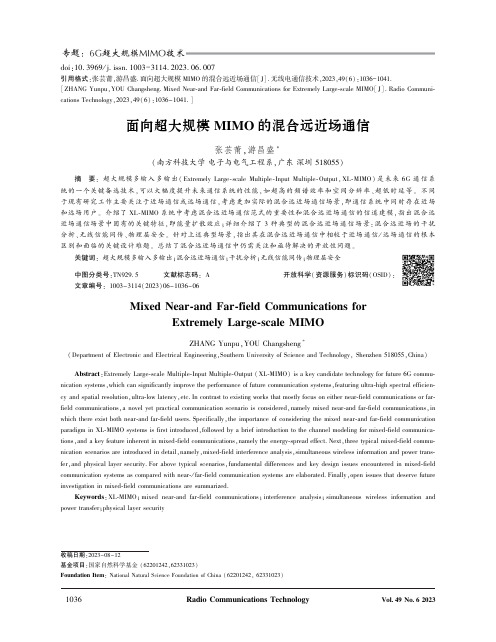
doi:10.3969/j.issn.1003-3114.2023.06.007引用格式:张芸莆,游昌盛.面向超大规模MIMO的混合远近场通信[J].无线电通信技术,2023,49(6):1036-1041. [ZHANG Yunpu,YOU Changsheng.Mixed Near-and Far-field Communications for Extremely Large-scale MIMO[J].Radio Communi-cations Technology,2023,49(6):1036-1041.]面向超大规模MIMO的混合远近场通信张芸莆,游昌盛∗(南方科技大学电子与电气工程系,广东深圳518055)摘㊀要:超大规模多输入多输出(Extremely Large-scale Multiple-Input Multiple-Output,XL-MIMO)是未来6G通信系统的一个关键备选技术,可以大幅度提升未来通信系统的性能,如超高的频谱效率和空间分辨率㊁超低时延等㊂不同于现有研究工作主要关注于近场通信或远场通信,考虑更加实际的混合远近场通信场景,即通信系统中同时存在近场和远场用户㊂介绍了XL-MIMO系统中考虑混合远近场通信范式的重要性和混合远近场通信的信道建模,指出混合远近场通信场景中固有的关键特征,即能量扩散效应;详细介绍了3种典型的混合远近场通信场景:混合远近场的干扰分析㊁无线信能同传㊁物理层安全㊂针对上述典型场景,指出其在混合远近场通信中相较于近场通信/远场通信的根本区别和面临的关键设计难题㊂总结了混合远近场通信中仍需关注和亟待解决的开放性问题㊂关键词:超大规模多输入多输出;混合远近场通信;干扰分析;无线信能同传;物理层安全中图分类号:TN929.5㊀㊀㊀文献标志码:A㊀㊀㊀开放科学(资源服务)标识码(OSID):文章编号:1003-3114(2023)06-1036-06Mixed Near-and Far-field Communications forExtremely Large-scale MIMOZHANG Yunpu,YOU Changsheng∗(Department of Electronic and Electrical Engineering,Southern University of Science and Technology,Shenzhen518055,China) Abstract:Extremely Large-scale Multiple-Input Multiple-Output(XL-MIMO)is a key candidate technology for future6G commu-nication systems,which can significantly improve the performance of future communication systems,featuring ultra-high spectral efficien-cy and spatial resolution,ultra-low latency,etc.In contrast to existing works that mostly focus on either near-field communications or far-field communications,a novel yet practical communication scenario is considered,namely mixed near-and far-field communications,in which there exist both near-and far-field users.Specifically,the importance of considering the mixed near-and far-field communication paradigm in XL-MIMO systems is first introduced,followed by a brief introduction to the channel modeling for mixed-field communica-tions,and a key feature inherent in mixed-field communications,namely the energy-spread effect.Next,three typical mixed-field commu-nication scenarios are introduced in detail,namely,mixed-field interference analysis,simultaneous wireless information and power trans-fer,and physical layer security.For above typical scenarios,fundamental differences and key design issues encountered in mixed-field communication systems as compared with near-/far-field communication systems are elaborated.Finally,open issues that deserve future investigation in mixed-field communications are summarized.Keywords:XL-MIMO;mixed near-and far-field communications;interference analysis;simultaneous wireless information and power transfer;physical layer security收稿日期:2023-08-12基金项目:国家自然科学基金(62201242,62331023)Foundation Item:National Natural Science Foundation of China(62201242,62331023)0㊀引言自2020年以来,5G移动通信系统正在全球广泛使用和部署[1-2]㊂然而,增强现实㊁全息视频和自动驾驶等新兴应用正在推动当今的5G通信系统向未来的6G移动通信系统的演进,以满足更严格的性能要求,包括前所未有的高数据速率㊁超高可靠性㊁全球覆盖㊁超密集连接等[3-6]㊂然而,现有的5G 技术可能无法完全满足这些要求,从而激发了研究6G创新技术的需求㊂而且,国际电信联盟(Interna-tional Telecommunication Union,ITU)于2023年6月发布了‘IMT面向2030及未来发展的框架和总体目标建议书“,列出了6G的定制化关键性能指标(Key Performance Indicators,KPIs),其中包含相较于5G通信系统的9个增强性能指标和6个新定义的性能指标[6]㊂值得注意的是,这些新定义的KPIs 对6G提出了更加严格的要求,因此研究6G的使能技术成为必要㊂在许多被畅想的6G使能技术中,超大规模多输入多输出(Extremely Large-scale Mul-tiple-Input Multiple-Output,XL-MIMO)已成为一项极其有前景的关键技术,可满足未来6G无线网络不断增长的性能需求,例如超高频谱效率和空间分辨率等㊂然而,6G XL-MIMO技术的使用和部署将从根本上导致电磁(Electromagnetic,EM)传播建模发生变化,即从传统的远场通信(平面波前传播)转向新的近场无线通信(球面波前传播)[7-9]㊂以XL-MIMO系统举例,其相应的电磁场可以划分为三个区域:①感应近场区域(Reactive Near-field Region);②辐射近场区域(Radiative Near-field Re-gion);③远场区域(Far-field Region)㊂现有的近场研究工作大多聚焦于辐射近场区域(也称为菲涅尔区域)㊂此外,瑞利距离(Rayleigh Distance)被广泛作为区分近场区域和远场区域的边界,其数学表达式为2D2/λ,其中D和λ分别表示天线阵列孔径和载波波长㊂值得注意的是,相较于纯近场通信或者远场通信,混合远近场通信是更为实际且极易出现的通信场景,即系统中同时存在近场用户和远场用户[10-11]㊂例如,考虑一个典型的XL-MIMO通信系统,其中配备孔径为0.5m的XL-MIMO基站以30GHz频率与用户进行通信㊂在这种情况下,众所周知的瑞利距离约为50m,约等于蜂窝系统中小区半径的一半㊂因此,考虑一些典型的通信场景,极大可能会出现一些用户位于近场区域,而其他用户位于远场区域的情况㊂而且,混合远近场通信范式的出现将会引发通信系统中新的设计难题㊂具体来说,混合远近场通信将导致一些经典通信场景的设计发生根本性的范式转变,使得针对于传统远场通信或近场通信的系统设计不再适用,因此需要根据混合远近场通信系统的特点和性能需求进行针对性设计㊂1㊀混合远近场通信基础和关键特征首先介绍混合远近场通信系统的信道模型,然后指出混合远近场通信区别于远场通信和近场通信的关键特征㊂1.1㊀远场和近场通信用户的信道模型为了清楚地展示混合远近场通信的信道模型,如图1所示,考虑一个典型的混合远近场无线通信系统,其中配备有天线数目为N的XL-MIMO基站同时服务一个单天线近场通信用户和一个单天线远场通信用户㊂下面分别给出远场用户和近场用户的信道建模过程㊂图1㊀一个典型的混合远近场无线通信系统Fig.1㊀A typical mixed-field wireless communication system 首先考虑远场用户,即到XL-MIMO基站端的距离大于定义的瑞利距离,则其信道建模遵循远场平面波传播模型,给定如下:h far=㊀N h far a(ψ),式中:h far表示远场用户和XL-MIMO基站之间的复值信道增益㊂a(ψ)表示远场信道导向矢量:a(ψ)=1㊀N[1,e jπψ, ,e jπ(N-1)ψ]T,式中:ψ=2d cos(φ)/λ表示远场用户相对XL-MIMO 基站的空间角度,φ表示信号相对于XL-MIMO基站中心的离开角(Angle of Departure,AoD),d表示天线间距㊂对于近场用户,其信道建模应遵循更为精确的球面波传播模型[12],给定如下:h near=㊀N h near b(θ,r),式中:h near表示近场用户和XL-MIMO基站之间的复值信道增益㊂b(θ,r)表示近场信道导向矢量: b(θ,r)=1㊀N e-j2π(r(0)-r)/λ, ,e-j2π(r(N-1)-r)/λ[]T,式中:θ=2d cos(ϕ)/λ表示近场用户相对于XL-MI-MO基站的空间角度,ϕ表示信号相对于XL-MIMO中心的AoD;r(n)=㊀r2+δ2n d2-2rθδn d表示XL-MIMO 基站端第n个天线到近场用户之间的距离,δn= 2n-N+12,n=0,1, ,N-1㊂值得注意的是,与远场信道导向矢量仅取决于角度不同,近场信道导向矢量同时依赖于角度和距离㊂而且,远场信道导向矢量是近场信道导向矢量的特殊形式,当用户和XL-MIMO基站间的距离大于瑞利距离时,近场信道导向矢量退化为远场信道导向矢量㊂综上所述,一个简单的混合远近场信道模型可以建模为:h mixed-field=h near+h far=㊀N h near b(θ,r)+㊀N h far a(ψ)㊂上式给出了混合场通信信道的一个简单例子,其是远场用户视距(Line-of-Sight,LoS)链路和近场用户LoS信道的叠加㊂1.2㊀混合远近场通信的固有特征:能量扩散如图2所示,混合远近场通信的一个关键特征是能量扩散效应㊂考虑在传统远场通信中被广泛采用的基于离散傅里叶变换(Discrete Fourier Trans-form,DFT)的角度域码本㊂当XL-MIMO基站选定码本中的特定码字发射定向波束以服务远场用户时,处于远场用户一定角度范围内(-0.1~0.5)的近场用户都将接收到高强度的信号㊂值得注意的是,这一独特的现象是混合远近场通信中的固有特征,其使得混合远近场通信显著区别于纯远场或近场通信㊂因此现有的针对于远场或近场通信的经典设计不再适用,使得混合场通信的专有设计成为必要㊂接下来,主要从三种典型通信场景出发,详尽地描述这些典型场景在混合场通信中相较于远场通信和近场通信的根本区别㊂图2㊀混合场通信中能量扩散效应的图解Fig.2㊀Illustration of the energy-spread effect in mixed-field communications2㊀混合远近场通信典型场景2.1㊀混合远近场通信的干扰分析考虑混合远近场通信中的多用户干扰分析[13]㊂不同于传统远场通信或近场通信中的多用户干扰产生机制,由于能量扩散效应的存在,混合远近场通信中的多用户干扰呈现出新的特点㊂具体来说,考虑不同通信场景下的多用户干扰㊂如果用户都处于传统的远场区域,空分多址接入(Spatial Division Multiple Access,SDMA)和波束分多址接入[14](Beam Division Multiple Access,BDMA)技术可以用来同时服务多个用户,并且用户间干扰较低㊂这是因为指向不同远场通信用户的定向波束在角度域上具有渐近正交性,从而有效消除用户间干扰㊂接下来,如果用户位于近场区域,新兴的位分多址接入[15](Loca-tion Division Multiple Access,LDMA)技术可以在非常低干扰下通过利用近场波束聚焦性质,同时为处于不同角度和/或距离的近场通信用户提供通信服务㊂需要强调的是,LDMA是利用近场中独特的波束聚焦效应来实现的,该效应使近场波束能够聚焦在特定的位置(范围),而不是像传统远场通信中那样波束打向特定的方向㊂然而,对于全新的混合远近场多用户通信场景,用户间的干扰分析变得非常复杂㊂为了更加清楚地描述混合场通信场景中干扰的特征,如图3所示,考虑一个典型混合场通信系统中包含一个远场用户和一个近场用户,其中XL-MIMO 基站的天线数目为256,信号传输功率为30dBm,载波频率30GHz,XL-MIMO 基站和用户的距离为7.2m㊂图3㊀近场用户的干扰功率与远场波束的空间角度的关系Fig.3㊀Interference power at a near-field user versus thespatial angle of a far-field beam一个有趣的观察是,即使近场用户位于与远场用户不同的空间角度(参见阴影区域),近场用户也会受到来自远场波束的强烈干扰,这与仅存在近场用户或远场用户场景中的结果存在显著差异㊂而且,混合远近场通信的干扰机制已经在文献[13]中进行了全面且详尽的研究㊂具体来说,远场用户对近场用户的干扰本质上是由近场用户的信道导向矢量和远场波束之间的相关性决定的,其数学描述定义为:η(θ,r ,ψ)=|b H(θ,r )a (ψ)|ʈ1N 12ðN -1n =0e jπn2d (1-θ2)2r-n θ-ψ+d (n -1)(1-θ2)2r()()㊂值得注意的是,上述定义的相关性函数可以由菲涅耳函数很好地近似,由下式给出:η(θ,r ,ψ)ʈG (β1,β2)=C ^(β1,β2)+j S ^(β1,β2)2β2,式中:β1=(θ-ψ)㊀r d (1-θ2),β2=N 2㊀d (1-θ2)r且C ^(β1,β2)=C (β1+β2)-C (β1-β2),S ^(β1,β2)=S (β1+β2)-S (β1-β2)㊂此近似的具体证明可以参考文献[13]㊂上述混合场中的干扰近似表达式给出了一个重要结果,即混合场中用户之间的干扰是由函数G (β1,β2)以及两个参数β1和β2给出的㊂更具体地说,β1是远场用户的空间角度㊁近场用户的空间角度和距离的函数,而β2则由XL-MIMO 基站的天线数目以及近场用户的角度和距离共同决定㊂文献[13]针对这些关键参数对混合场干扰的具体影响已经进行了全面而详尽的研究㊂总的来说,当XL-MIMO 基站的天线数量和近场用户距离相对较小,和/或近场用户和远场用户空间角度差较小时,用户间存在强干扰[13]㊂综上所述,混合远近场通信中独特且固有的能量扩散效应将不可避免地导致更为复杂的多用户干扰问题,也为后续的干扰消除方案设计带来严峻的挑战㊂2.2㊀混合远近场通信的无线信能同传从无线使能通信(Wireless Power Transfer,WPT)的角度来看,混合远近场通信的能量扩散效应可以被利用来提升系统能量采集性能[16]㊂具体来说,为远场通信用户服务的基于DFT 的波束引起的能量泄漏可以被利用为近场能量采集用户充电㊂特别地,考虑一个典型的混合场无线信能同传场景(Simultaneous Wireless Information and Power Trans-fer,SWIPT),其中能量采集(Energy Harvesting,EH)用户和信息解码(Information Decoding,ID)用户分别假设位于XL-MIMO 系统的近场和远场区域㊂需要强调的是,混合远近场SWIPT 的系统设计也面临着新的挑战㊂例如,通过利用近场波束聚焦特性,近场EH 用户的波束赋形应精心设计,以最大限度地提高EH 效率,同时最大可能地减少对远场ID 用户的干扰㊂在为远场ID 用户设计波束赋形时应充分利用能量扩散效应,当近场EH 用户与远场ID 用户位于相似的角度时,服务于远场用户的波束可以机会性地为近场EH 用户充电㊂此外,应精心设计基站的功率分配,以平衡混合场SWIPT 系统中新的远近权衡与波束聚焦和能量扩散的影响㊂现有的研究工作[16]表明,混合场SWIPT 系统中的波束调度显著不同于传统远场SWIPT系统的波束调度设计㊂具体而言,如图4所示,混合场SWIPT 系统的最优设计需要调度近场EH 用户,而远场SWIPT 系统最优设计表明只需调度ID 用户[17]㊂图4㊀混合场SWIPT系统波束调度图Fig.4㊀Illustration of beam scheduling in mixed-field SWIPT 2.3㊀混合远近场通信的物理层安全考虑混合场物理层安全(Physical Layer Security, PLS)㊂针对于传统的远场PLS,在角度域区分合理用户和窃听用户即可实现安全通信[18]㊂对于新兴的近场PLS,通过利用近场通信所带来的额外的距离域分辨率,处于同一空间角度而不同距离的合理用户和窃听用户也可实现安全通信[19]㊂然而,针对于混合场PLS,实现安全通信极具挑战性㊂具体来说,考虑一类具有挑战性的混合场PLS通信场景,即窃听用户位于XL-MIMO系统的近场区域,而合理用户处于远场区域㊂在这类场景中,由于窃听用户可以在一定范围内从合理用户的信息泄漏(Information Leakage)中窃听合理用户的信息,同时处于近场的窃听用户享有更好的信道条件,因此针对这类场景的混合场PLS极具挑战性,这也凸显了混合场PLS方案设计的必要性㊂3㊀混合远近场通信开放性研究问题3.1㊀混合远近场通信的信道建模信道建模为混合远近场通信奠定了基础㊂在现有的研究工作中,广泛假设混合场信道模型由近场和远场LoS信道组成㊂然而,需要研究更实际和通用的混合远近场信道模型㊂例如,研究用于混合远近场通信的更复杂的多径信道至关重要,该信道建模考虑了XL-MIMO系统远场和/或近场中周围环境散射体引起的多径㊂同时,混合远近场通信中可视区域[20](Visible Region,VR)现象也会更加显著㊂这是因为除了环境散射体会影响不同用户的VR,近场和远场之间的相互作用也会进一步使不同用户的VR复杂化,需要正确建模这种影响㊂此外,除了确定性信道模型之外,近场信道模型多呈现出近场空间相关性和非平稳性㊂因此,混合远近场的信道建模也需要考虑随机性的近场信道模型㊂3.2㊀混合远近场通信的波束管理为了实现高质量的通信服务,混合远近场通信的波束管理也至关重要[10]㊂具体来说,现有的波束训练方法假设用户全部位于远场区域或近场区域㊂对于混合远近场通信场景下用户同时分布在近场和远场区域,如何设计适用于近场和远场通信场景的统一波束训练方法是一个关键问题㊂这需要进一步深入研究近场和远场波束训练方法的有效融合㊂而且,对于混合远近场的波束追踪,考虑远场和近场用户的高移动性,远场用户可能会进入近场区域,近场用户也可能进入远场区域㊂这在设计混合场波束追踪算法时需要同时考虑对用户所处场的预测,以及相应的波束追踪算法设计㊂混合场的波束调度也是一个实际而具有挑战性的问题㊂由于混合场通信场景中存在新的远近均衡(Near-to-Far Tradeoff),因此在设计混合场波束调度方法时需要精巧地设计以达到一个系统的均衡㊂3.3㊀混合远近场通信的收发器设计由于XL-MIMO系统通常工作在高频段,高功耗和硬件复杂性成为核心问题㊂一个理想的解决方案是利用经典的混合波束成形技术来降低硬件和能源成本[21]㊂然而,随着XL-MIMO天线数目的增加,经典的混合波束成形技术仍然具有很高的复杂度㊂因此,考虑采用子连接架构㊁动态子阵列架构和透镜天线阵列等进行适当设计,以实现复杂度和性能之间的权衡㊂由于混合场通信系统中同时存在近场和远场用户,因此需要考虑新型的收发器结构设计,使之可以同时服务于两类用户㊂此外,高频率伴随的高宽带会在近场通信中产生波束分裂现象(Beam Split),现有的基于移相器的模拟组件无法处理此问题㊂一种有效的解决方案是在射频链路和移相器之间采用额外的电路来生成与频率相关的相移,从而将波束聚焦在整个带宽上㊂这个方向仍处于早期阶段,值得进一步研究在射频链和移相器之间采用额外的真时延[22](True Time Delay,TDD)电路来产生与频率相关的相移,从而将波束聚焦在整个带宽上㊂4 结论主要考虑6G XL-MIMO系统中一个典型且实际的混合远近场通信场景,即系统中同时存在近场用户和远场用户㊂针对这一新兴通信范式,强调了6G XL-MIMO系统中考虑此范式的重要性㊂介绍了其固有的能量扩散现象㊂考虑了混合场通信的三种典型场景:混合场干扰分析㊁SWIPT和PLS,并着重阐述混合远近场通信中三种典型场景和传统远场及近场通信的基本区别和新的设计思路㊂总结了混合远近场通信需要研究和亟待解决的几个关键问题㊂参考文献[1]㊀ANDREWS J G,BUZZI S,CHOI W,et al.What will5Gbe?[J].IEEE Journal on Selected Areas in Communica-tions,2014,32(6):1065-1082.[2]㊀SHAFI M,MOLISCH A F,SMITH P J,et al.5G:A TutorialOverview of Standards,Trials,Challenges,Deployment,and Practice[J].IEEE Journal on Selected Areas in Com-munications,2017,35(6):1201-1221.[3]㊀张平,牛凯,田辉,等.6G移动通信技术展望[J].通信学报,2019,40(1):141-148.[4]㊀邵泽才,袁弋非,李娜,等.6G网络能耗面临的机遇与挑战[J].无线电通信技术,2023,49(3):385-392. [5]㊀王承祥,黄杰,王海明,等.面向6G的无线通信信道特性分析与建模[J].物联网学报,2020,4(1):19-32. [6]㊀YOU X H,WANG C X,HUANG J,et al.Towards6GWireless Communication Networks:Vision,EnablingTechnologies,and New Paradigm Shifts[J].中国科学:信息科学(英文版),2021,64(1):5-78.[7]㊀TU-R WP5D.Recommendation ITU-R M.[IMT.Frame-work for2030and Beyond].[EB/OL].[2023-08-10].https:ʊwww.itu.int/md/R19-WP5D-C/en. [8]㊀WANG Z,ZHANG J,DU H,et al.Extremely Large-scaleMIMO:Fundamentals,Challenges,Solutions,and FutureDirections[J/OL].(2023-04-06)[2023-07-26].https:ʊ/abs/2209.12131.[9]㊀CUI M,WU Z,LU Y,et al.Near-field MIMO Communica-tions for6G:Fundamentals,Challenges,Potentials,andFuture Directions[J].IEEE Communications Magazine,2022,61(1):40-46.[10]YOU C,ZHANG Y,WU C,et al.Near-field Beam Man-agement for Extremely Large-scale Array Communications[J/OL].(2022-01-22)[2023-08-10].https:ʊarxiv.org/abs/2306.16206.[11]HAN C,CHEN Y,YAN L,et al.Cross Far-and Near-fieldWireless Communications in Terahertz Ultra-large AntennaArray Systems[J/OL].(2023-08-03)[2023-08-10].https:ʊ/abs/2301.03035.[12]ZHANG Y,WU X,YOU C.Fast Near-field Beam Trainingfor Extremely Large-scale Array[J].IEEE Wireless Com-munications Letters,2022,11(12):2625-2629. [13]ZHANG Y,YOU C,CHEN L,et al.Mixed Near-and Far-field Communications for Extremely Large-scale Array:An Interference Perspective[J/OL].(2023-01-29)[2023-08-10].https:ʊ/abs/2301.07277.[14]SUN C,GAO X,JIN S,et al.Beam Division MultipleAccess Transmission for Massive MIMO Communications[J].IEEE Transactions on Communications,2015,63(6):2170-2184.[15]WU Z,DAI L.Multiple Access for Near-field Communica-tions:SDMA or LDMA?[J].IEEE Journal on SelectedAreas in Communications,2023,41(6):1918-1935. [16]ZHANG Y,YOU C,YUAN W,et al.Joint Beam Schedu-ling and Power Allocation for SWIPT in Mixed Near-andFar-field Channels[J/OL].(2023-04-17)[2023-08-10].https:ʊ/abs/2304.07945. [17]XU J,LIU L,ZHANG R.Multiuser MISO Beamforming forSimultaneous Wireless Information and Power Transfer[J].IEEE Transactions on Signal Processing,2014,62(18):4798-4810.[18]吴宣利,许智聪,王禹辰,等.基于信道相关性的物理层安全性能分析[J].通信学报,2021,42(3):65-74. [19]DONG Z,ZENG Y.Near-field Spatial Correlation forExtremely Large-scale Array Communications[J].IEEECommunications Letters,2022,26(7):1534-1538. [20]HAN Y,JIN S,WEN C K,et al.Channel Estimation forExtremely Large-scale Massive MIMO Systems[J].IEEEWireless Communications Letters,2020,9(5):633-637.[21]YU X,SHEN J C,ZHANG J,et al.Alternating Minimiza-tion Algorithms for Hybrid Precoding in Millimeter WaveMIMO Systems[J].IEEE Journal of Selected Topics inSignal Processing,2016,10(3):485-500. [22]崔铭尧,谭竞搏,戴凌龙.面向信道簇模型的太赫兹宽带混合预编码[J].中国科学(信息科学),2023,53(4):772-786.作者简介:张芸莆㊀男,(1995 ),南方科技大学访问研究生㊂主要研究方向:智能反射面㊁近场通信㊂(∗通信作者)游昌盛㊀男,(1991 ),博士,助理教授㊂主要研究方向:智能反射面㊁近场通信㊂。
多节点协同中继信道容量分析及功率分配
多节点协同中继信道容量分析及功率分配黄英;魏急波;雷菁【摘要】基于译码—转发(DF)模式,在信道状态信息未知,源节点发射功率与各中继节点发射总功率分别受限于P1、P2的假设下,针对带直传(DT)和不带直传2种模型的多节点协同中继,进行了信道容量上下限的分析和推导.在功率限固定的情况下,分析了容量与中继节点数目之间的关系,给出了容量随中继节点数目增加而提高所需的条件.在功率限之和受限的情况下,获得了2个功率限的最佳分配.理论分析和仿真结果都表明:源到中继的信道条件较好时,只有当增加的新链路性能优于现有链路的平均值时才能提高容量;2种中继模型在功率限最佳分配下可获得最大容量.%Based on DF mode,and under the power constraint P1 (source transmission) and P2 (total relay transmission) ,the capacity of multi-node cooperative relay without CSI was analyzed,which is divided into two models: with DT and without DT. Given the fixed power constraint,the relationship between the capacity and the number of relay was achieved . The condition to improve the capacity as relay number increasing was proposed. When the sum of P1 and P2 was subject to another power constraint, the optimal power allocation was achieved. Theoretical analysis and simulation shows that when the channel condition between the source and the relay is better,the capacity increases only when the new link is better than the average existing links. The capacity is maximum at the optimal power allocation at two models.【期刊名称】《解放军理工大学学报(自然科学版)》【年(卷),期】2012(013)002【总页数】5页(P119-123)【关键词】中继信道;译码-转发;信道容量;直传;信道状态信息【作者】黄英;魏急波;雷菁【作者单位】国防科技大学电子科学与工程学院,湖南长沙410073;国防科技大学电子科学与工程学院,湖南长沙410073;国防科技大学电子科学与工程学院,湖南长沙410073【正文语种】中文【中图分类】TN929.5协同中继使在特定区域内只有单根天线的一些中继或终端形成了一个虚拟天线阵,从而达到了空间分级的效果,显著提高了用户的服务质量和系统的吞吐量。
MIMO功率分配算法,注水原理
1.1功率注水算法注水算法是根据某种准则,并根据信道状况对发送功率进行自适应分配,通常是信道状况好的时刻,多分配功率,信道差的时候,少分配功率,从而最大化传输速率。
实现功率的“注水”分配,发送端必须知道CSI 。
当接收端完全知道信道而发送端不知道信号时,发送天线阵列中的功率平均分配是合理的。
当发送端知道信道,可以增加信道容量。
考虑一个1⨯r 维的零均值循环对称复高斯信号向量s ~,r 为发送信道的秩。
向量在传送之前被乘以矩阵V (H V U H ∑=)。
在接收端,接受到的信号向量y 被乘以H U 。
这个系统的有效输入输出关系式由下式给出:n s M E n U s V V U U M E n U s HV U M E y Ts H H HTs H H T s ~~~~~+∑=+∑=+=s其中y ~是1⨯r 维的变换的接受信号向量,n ~是协方差矩阵为rH I N n n 0}~~{=ξ的零均值循环对称复高斯1⨯r 变换噪声向量。
向量s ~必须满足T HM s s =}~~{ξ已限制总的发送能量。
可以看出ii i Tsi n s M E y ~~~+=λ,i=1,2,…,r MIMO 信道的容量是单个平行SISO 信道容量之和,由下式给出∑=+=ri i T is N M E C 12)1(log λγ其中}{2i i s ξγ=(i=1,2,…,r)反映了第i 个子信道的发送能量,且满足T ri iM =∑=1γ。
可以在子信道中分配可变的能量来最大化互信息。
现在互信息最大化问题就变成了:∑==+∑==ri i T i s M N M E C r i T i 1)2)1(log max 1λγγ最大化目标在变量),..,1(r i i =γ中是凹的,用拉格朗日法最大化。
最佳能量分配政策}0),max {(0is T opt i E N M λμγ-= ∑==ri T opt iM 1γ注水算法:Step1:迭代计数p=1,计算]11[1110∑+-++-=p r isTE N p r M λμStep2:用μ计算is T i E N M λμγ0-=,i=1,2,…,r -p+1 Step3:若分配到最小增益的信道能量为负值,即设01=+-p r γ,p=p+1,转至Step1. 若任意i γ非负,即得到最佳注水功率分配策略。
相关阴影Rician衰落信道上MPSK的性能
相关阴影Rician衰落信道上MPSK的性能江林超;李光球【摘要】研究多输入多输出相关阴影Rician衰落信道上正交空时分组编码M进制相移键控的平均符号错误概率性能.当信道衰落参数为正整数时,使用矩生成函数方法推导了相关视距分量、独立散射分量条件下的阴影Rician衰落信道上M进制相移键控平均符号错误概率性能的精确闭合表达式.利用获得的精确闭合表达式可以分析信道衰落参数和天线间的相关性对M进制相移键控平均符号错误概率性能的影响.【期刊名称】《杭州电子科技大学学报》【年(卷),期】2010(030)001【总页数】4页(P14-17)【关键词】多输入多输出系统;阴影莱斯衰落;相移键控;空时分组编码;错误概率【作者】江林超;李光球【作者单位】杭州电子科技大学通信工程学院,浙江,杭州,310018;杭州电子科技大学通信工程学院,浙江,杭州,310018【正文语种】中文【中图分类】TN9110 引言衰落信道上空时分组码(Space-Time Block Code,STBC)的性能研究是当前无线通信的研究热点。
文献1推导了平坦瑞利衰落信道上STBC编码的M进制相移键控(M-ary Phase Shift Keying,MPSK)平均符号错误概率(Symbol Error Probability,SEP)的闭合表达式。
文献2推导了平坦Nakagami衰落信道上STBC 编码的MPSK平均SEP性能的精确闭合表达式。
文献3推导了相关Nakagam i 衰落信道上STBC编码的MPSK平均SEP性能的精确闭合表达式。
相关阴影Rician衰落信道模型是陆地移动卫星系统的典型信道模型,文献4推导了相关阴影Rician衰落信道上STBC编码的MPSK平均误比特率(Bit Error Rate,BER)性能的精确闭合表达式。
文献4局限于研究MPSK的平均BER性能,对于MPSK精确的平均SEP性能没有给出相应的研究成果。
多输入多输出的技术

多输入多输出技术学院:工商管理学院专业:市场营销专业姓名:杨洋班级:B1101学号:1013110122内容摘要:MIMO是指多输入多输出(Multiple In Multiple Out),它是指一台设备用多个天线在同一个频道内同时发送或者接收多个独立的数据流。
通过这种机制,用户可以获得更高的传输速率和更远的传输距离。
MIMO是目前IEEE802.11n标准的核心技术。
除了多天线外,还需要配合专门的软件才能真正实现这个技术的优点。
综合各种必要条件,多天线技术和软件保证了数据可以在更远的距离和更多的干扰中更稳定的发送和接收。
总之一句话,MIMO技术带给您更远的传输距离和更高的传输速率。
在有些情况下,MIMO技术可以在超过300英尺的距离上达到100Mbps的传输速率。
MIMO(Multiple-Input Multiple-Out-put)系统是一项运用于802.11n的核心技术。
802.11n是IEEE继802.11b\a\g后全新的无线局域网技术,速度可达600Mbps。
同时,专有MIMO技术可改进已有802.11a/b/g网络的性能。
该技术最早是由Marconi于1908年提出的,它利用多天线来抑制信道衰落。
根据收发两端天线数量,相对于普通的SISO(Single-Input Single-Output)系统,MIMO还可以包括SIMO(Single-Input Multi-ple-Output)系统和MISO(Multiple-Input Single-Output)系统。
关键词:发展史技术分类研究状况重大历程技术应用总结发展史:MIMO波束成型技术的缺点乃是在都市的环境中,信号容易朝向建筑物或移动的车辆等目标分散,因而模糊其波束的集中特性(即相长干涉),丧失多数的信号增益及减少干扰的特性。
然而此项缺点却随着空间分集及空间多工的技术在 1990 年代末的发展,而突然转变为优势。
这些方法利用多径(multipath propagation)现象来增加资料吞吐量、传送距离,或减少比特错误率。
MIMO技术的简介
TELE 9754 Coding and InformationTheoryResearch Workshop ReportAbstract—Mobile wireless communication has become one of the most important aspects of our daily life. The continuously increasing usage has imposed great pressure upon telecommunication system where the availability of channel capacity and spectral resources are limited. Multiple Input Multiple Output (MIMO) is considered as one of the possible solutions to the above problem and has attracted considerable attention among researchers and engineers in the field of mobile communication due to the great advantages it exhibits. In recent years, MIMO technology has been developed into more sophisticated forms and utilized in some common communication devices around us. This report is intended to provide readers with a brief review of the historical and technological developments of MIMO, and its applications.I. INTRODUCTIONOur wireless communication systems have undergone remarkable developments and progresses in the past 20 years, from 1G to 4G and the upcoming 5G. Such systems have provided our life with significant conveniences which were otherwise impossible and unachievable before the 1980s. However, under the condition of limited bandwidth resources and channel capacity, the developing communication scheme is unable to meet the fast growing demand from users of mobile devices. In other words, our communication system has somewhat attained its bottleneck and needs some new technology to enhance its performance. On the other hand, MIMO equipped with modern efficient signal processing techniques and processing hardware demonstrates prominent characteristics that could be taken to mitigate the above problems. MIMO can be defined, in simple terms, as a system which consists of multiple antennas at both the transmitter and receiver sides [6]. A systematic diagram of MIMO is illustrated by Figure 1.Figure 1. Systematic diagram of a MIMO systemThe underlying fact which enables MIMO to attract intense attention is that it could exploit the advantages of beamforming gain, spatial diversity and spatial multiplexing to enhance the performance of a communication system without extra consumption of spectral resources.The content of this report is organized in six separate sections. Section II offers readers a set of abbreviations used throughout the report. Section III illustrates the historical developments and milestones of MIMO from theory to implementations. Section IV introduces, in general sense, how MIMO functions and achieves the aforementioned advantages. Section V categorizes MIMO into various classes based on the properties it composes and some comparisons among them would be made. Section VI provides some examples of application of MIMO in modern communication scheme. Finally, a brief conclusion will be drawn in Section VI. Additional information can be found by referring to the Appendix section.II. TABLE OF ABBREVIATIONSThe following table (Table 1) lists a set of commonlyA BRIEF REVIEW ON MIMO TECHNOLOGY AND ITS APPLICATIONSLikai Ma z3326280used abbreviations to which will be referred in the following sections of this report. Table 1. Table of abbreviations III. HISTORICAL DEVELOPMENT OF MIMO [1] The history of MIMO can be dated back several decades ago. Although the idea of MIMO was not proposed until the 1970s, antenna arrays, also known as smart antennas (illustrated in Figure 2) had been developed to take the advantage of diversity and enhance wireless transmission and reception in analogue communications. CLASSIFICATION OF MIMO Figure 2. An example of antenna array. The idea of MIMO was first conceived in the 1970s in Bell Laboratory, which was inspired by the desire to overcome the problem of bandwidth limitation and interference in transmission cables. Such idea was too difficult to be realized and had remained in the form of theory for a long period of time, due to the limitation that the processing hardware and signal processing algorithms available at that stage was unable to support MIMO signal processing. Nevertheless, the theory of MIMO had continued to be enriched by some of the early researchers ’, including A.R Kaye, D.A George, Branderburg, Wyner and W. Van. Etten. In the late 1980s, MIMO theory had further been developed by Jack Salz and Jack Winters whose work centralizedaround the idea of beamforming.The concept of SM was proposed in 1993 by Arogyaswami Paulraj and Thomas. In 1996, Greg Raleigh and Gerard J. Foschini further developed the approaches towards MIMO using co-located antennas at the transmitter. Significant breakthrough in practical application of MIMO did not take place until the late 1990s. In 1998, SM was first demonstrated in the formFigure 2.Timeline of development of MIMO.of prototype in Bell Lab. Since then, the development of MIMO had been accelerated and some products with such technology integrated started to be available commercially. In 2002, Iospan Wireless Inc. launch the first commercial product with MIMO embedded, which was a milestone in the real application of this technology. Later, in 2005, the first standard of WLAN (IEEE 802.11n), also commonly known as Wi-Fi, with MIMO-OFDM was produced by Airgo Networks and has become more and more popular since then. The more detailed historical development of MIMO is depicted as a timeline and can be found in Figure 2.IV. HOW DOES MIMO WORKThe underlying principle of MIMO is that signals transmitted and received at both the transmitter and receiver sides combine together so that either parallel data sub-streams are formed or SNR is improved [3]. The benefits that MIMO exploits are known as beamforming, spatial diversity and spatial multiplexing.Figure 3.Smith chart showing the technique of beamformingBeamforming is achieved by focusing energy in some desired angular direction through appropriate choice of antenna parameters [1, 2]. The Smith chart in Figure 3 illustrates the idea of beamforming where the main lob is pointing at a particular angular direction while the side lobes are significantly suppressed. When the channel between the transmitter and receiver are located within the range of LOS, MIMO can be configured to exploit the advantages of beamforming so that the antenna gains combine constructively and thereby an enhanced receiving power and SNR are attained in the link.When multiple copies of a signal are transmitted from the transmitter, they may subject to non-idealities in the communication channel, for example fading, reflection and refraction, to different extents. Multiple replicas of the signal incoming from different directions can be analyzed by employing some sophisticated DSP algorithms to recover the original transmitted signal if those signals are highly uncorrelated. Such technique is referred as spatial diversity [2]. In general, the more the extent of uncorrelation, the better the effect of spatial diversity. MIMO could also take the advantages of spatial diversity to improve the quality of the received signal (ie, increased SNR) and hence to provide a more reliable communication link.Figure 4. The MIMO channel capacity increases almost linearly with the number of transmitting or receiving antennas [5]In a fading channel, particularly Rayleigh fading with CSI known to the receiver, MIMO could form a number of parallel and independent sub-channels through which a code word can be divided into a number of pieces and transmitted separately [4, 5]. In other words, a higher transmission rate (channel capacity) could be achieved. In theoretical sense, the channel capacity increases approximately with the number of transmitting or receiving antennas, as depicted in Figure 4. This discovery has a tremendous implicationuponcommunication system, that higher information exchange rate can be achieved without consuming extra bandwidth, by introducing additional antennas at the transmitter and receiver sides. The benefits exploited by MIMO are summarized in the following table (Table 2).Table 2. Summary table of MIMO techniquesIn general, beamforming, spatial diversity and spatial multiplexing are three rivaling techniques that engineers should make appropriate decisions on what could be sacrificed in order to gain more advantages from the others. The inter-relations among these techniques are depicted in Figure 5 [2].Figure 5. Inter-relations among three MIMO techniquesAlthough they are rivaling factors, they are not necessarily mutually exclusive, meaning that by making appropriate decisions on to what extent those are used, one can design a communication scheme which employs a combination of those techniques such that certain degrees of advantages of them can be involved. Such decision should be based solely upon the specific engineering problem to be solved. V. V ARIOUS TYPES OF MIMOA MIMO system can be divided into different classes according to some specific criterion. A MIMO system is commonly classified according to the criterions that whether multiple users are able to be served simultaneously. The classifications is shown as in Figure 6.Figure 6. Classification of MIMOIn the case of multiple users, a MIMO system is referred as SU-MIMO if only a single user among them is served at a time. In contrary, the term MU-MIMO is defined for the case where multiple users can be served in parallel. The following figure (Figure 7) depicts a comparison between SU-MIMO and MU-MIMO.Figure 7. Comparison between SU-MIMO and MU-MIMO [7](A) SU-MIMO SYSTEM [7, 8]In SU-MIMO, the time-frequency resources are allocated entirely to a single user in a given communication session. If SM is employed, multiple sub-streams can then be created to scale up the channel capacity by the order dictated by the minimum of transmitting or receiving antennas. Different users can be served through the use of TDMA or FDMA.One can see that since the order of increases in channel capacity in SU-MIMO is limited by the transmitter or receiver side which consists of the smallest number of antennas, the improvements in channel throughput may be very limited, particularly for cellular communication networks. In other words, the user end would likely be the constraint on the enhancements of channel capacity. The number of antennas that can be integrated to the users’ mobile devices, such as mobile phones, is very limited, mainly due to limitations like portability and space availability.(B)MU-MIMO SYSTEM [7, 8]MU-MIMO can be considered as an extension to the theory of SU-MIMO. In a MU-MIMO system, multiple users can be served in parallel with the same time-frequency resources available. By exploiting the advantages of SM, the channel throughput for MU-MIMO can then be enhanced by the number of transmit antennas with sufficient number of users, namely a similar scaling principle carried by the case of SU-MIMO.As oppose to SU-MIMO, MU-MIMO better exploits the multiplexing gain provided by SM, which is achieved by allocating different users to different sub-channels. Different users can not only be served by employing TDMA or FDMA (in SU-MIMO), but also by means of SDMA. Therefore, MU-MIMO has more advantages over SU-MIMO in terms of time, frequency and spatial allocations.VI. APPLICATION OF MIMO IN MODERNCOMMUNICATION SCHEME [3]As the developments in both powerful signal processing hardware and more sophisticated MIMO models have become available in recent years, the application of MIMO in our modern communication systems have been made possible as oppose to the past, mainly by the ITU and 3GPP.Some of the common communication systems, including the 3G/4G network, Wi-Fi (IEEE 802.11n) and WiMAX have already integrated some MIMO technologies to a certain extent where various forms of MIMO have been deployed and different advantages are exploited. The use of MIMO technology in modern communication systems can be depicted by the following figure (Figure 8).Figure 8.Application of MIMO in modern communication systems.The current CDMA2000 standard, one of the 3G standards (WCDMA, CDMA2000 and TD-SCDMA) has adopted transmit diversity, while the WCDMA-based UMTS has also enabled implementation of transmit diversity and beamforming at base stations. Furthermore, the 3GPP LTE employs SU-MIMO with SM and STC. The more advanced version, so called 3GPP LTE-Advanced further extends from what has been designed in LTE and has involved MU-MIMO and multi-cell MIMO.In IEEE802.16 standard (also commonly known as WiMAX), MIMO-OFDMA, a technique that utilizes OFDM modulation scheme in combination with multiple antennas, has been deployed.IEEE802.11n or Wi-Fi is another commonly used communication standard and has implemented several MIMO technologies to enhance its data through put, channel capacity and overall performance. The techniques employed by Wi-Fi are mainly antenna selection, STC and beam forming. The following table (Table 3) provides a summary for the different MIMO technologies used in those communication schemes and their performance (data rate).Table 3. Summary of MIMO technologies in modern communication systems and their overall performances.VII. CONCLUSIONIn conclusion, the historical developments, classification and current applications associated with MIMO technologies have been outlined and reviewed in this report. It can be seen that MIMO has a great deal of advantages over other traditional communication technologies. MIMO can also be used in conjunction with other existing techniques including digital modulation (OFDM in particular), coding (STC, DPC and etc) and multiple access (TDMA and FDMA) in order to derive more powerful and efficient communication schemes and provide users with better communication quality. Although there still exits some compelling problems regarding the wide application of MIMO, one can see that such technology will be more extensively integrated in our future generation wireless communication systems.REFERENCE[1] Raut, Pravin W., and S. L. Badjate. "MIMO-Future Wireless Communication."[2] Sibille, Alain, Claude Oestges, and Alberto Zanella. MIMO: from theory to implementation. Academic Press, 2010.[3] Clerckx, Bruno, and Claude Oestges. MIMO Wireless Networks: Channels, Techniques and Standards for Multi-antenna, Multi-user and Multi-cell Systems. Academic Press, 2013.[4] Holter, Bengt. "On the capacity of the MIMO channel: A tutorial introduction."Proc. IEEE Norwegian Symposium on Signal Processing. 2001.[5] Liang, Yang Wen. "Ergodic and Outage Capacity of Narrowband MIMO Gaussian Channels." Dept. of Electrical and computer Engg. University of British Columbia, V ancouver, British Columbia (2005).[6] Telatar, Emre. "Capacity of Multi‐antenna Gaussian Channels." European transactions on telecommunications 10.6 (1999): 585-595.[7] Bauch, Gerhard, and Guido Dietl. "Multi-user MIMO for achieving IMT-Advanced requirements." Telecommunications, 2008. ICT 2008. International Conference on. IEEE, 2008.[8] Li, Qinghua, et al. "MIMO techniques in WiMAX andLTE: a feature overview."Communications Magazine, IEEE 48.5 (2010): 86-92.。
4.多输入多输出_MIMO_系统信道容量技术

C = W
2 这里的 d n 是H H
H
∑log
n= 1
2
d nE n d nE n 1+ = W log 2 1+ 2 2N t Ρ2 2 N tΡ n= 1
2
∏
H
2
( 9)
的特征值, 根据 det (M ) =
N
∏Κ(M ) 和 det ( I +
2N t Ρ2
E HH
M ) =
∏ (1 +
Κ(M ) ) , 可以得出:
=
n I n。 这样就可以得到信道容量:
由于从 N t 发射的信号相同, 多天线系统退化成 单有效信道, 这样就会有高的发射功率和接受分集。 由 ( 12) 式可以看出系统的信道容量随着发射和接 收天线的数量对数增长。 假设现在 N t = N r = 8 , 对
C = W log 2 det I n +
C = W log 2 1 + N tN r E
于 20dB 的 SN R 来说, 规范化的容量 C W 等于 12. 65 b it s H z。 这个系统与单天线系统相比, 分级增 益为 N tN r , 但分集增益会增加系统的复杂度。 如果不同天线发射的信号是不相同的, 信道元 素等于 1, 这样在等效信道中只有一个接收信号, 其 功率为 E r = N rE , 这样得到的信道容量为:
C = W log 2 1 + E
3 具有固定系数信道的 M I M O 容量
为了得到最大可能的信道容量, 本文对几种固 定系数信道进行验证。
《无线通信技术》 2005 年第 1 期 — 37 — © 1994-2010 China Academic Journal Electronic Publishing House. All rights reserved.
MIMO系统中若干关键问题的研究的开题报告
MIMO系统中若干关键问题的研究的开题报告摘要:在现代通信中,多天线技术(MIMO)逐渐成为了一种趋势。
MIMO系统能够同时利用多个发射天线和接收天线以提高信息传输速率和频谱利用率。
本文将研究MIMO系统中若干关键问题,包括功率分配、天线选择、信道估计和信道编码等方面。
该研究将探索这些问题的原理、方法和最新进展,以及在实际应用中的表现和限制。
最后,该研究将建议一种基于MIMO系统的实际应用中可能的解决方案,以促进MIMO技术的发展和应用。
一、研究背景和意义在现代通信中,移动终端和大规模的无线通信网络越来越重要。
然而,由于无线信道的限制,信息传输速率和频谱利用率受到了相当大的限制。
为了解决这些问题,多天线技术(MIMO)不断被研究和开发。
MIMO系统能够同时利用多个发射天线和接收天线以提高信息传输速率和频谱利用率。
随着MIMO技术的不断进步,当前主要存在四个重要的问题是功率分配、天线选择、信道估计和信道编码。
首先,功率分配问题是指在多个天线中分配适当的功率以最大化系统的性能。
往往,这需要将功率分配到各个发射天线上,使得接收信号的信噪比最大化。
其次,天线选择问题是指在多个天线中选择最好的天线以最大化系统的性能。
往往,这需要选择与接收机最匹配的发射天线以最大化接收信号的信噪比。
第三,信道估计问题是指从接收信号中提取出信道信息,以便正确解码信号并确定发送和接收之间的通道。
对于MIMO系统来说,信道估计是关键的,因为其多路径性质会使得信道很难建模。
最后,信道编码问题是指在MIMO系统中使用何种编码方式以提高编码的效率和减少误码率。
这些问题的研究对于理解MIMO系统的性能、限制和优化方案都有帮助。
因此,本文将研究MIMO系统中这些关键问题的原理、方法和最新进展,以及在实际应用中的表现和限制。
最后,该研究将建议一种基于MIMO系统的实际应用中可能的解决方案。
二、研究计划和方法本文将从功率分配、天线选择、信道估计和信道编码这四个方面入手,探索MIMO系统的关键问题。
MIMO
1MIMO Techniques for Wireless CommunicationsTa -Sung LeeDepartment of Communication Engineering National Chiao Tung UniversityE-mail: tslee@.twOutlinePart I: MIMO BackgroundMIMO OverviewMIMO Channel CapacityPart II: Space-Time Coding SchemesHigh Link Quality via Spatial Diversity—STBC/STTCHigh Spectral Efficiency via Spatial Multiplexing—LSTC Part III: MIMO for Future Wireless Communications 3GPPIEEE 802.11nIEEE 802.16 (-2004: WiMAX)MIMO Overview[1]-[3]Future trend for wireless communicationsFuture wireless applications create insatiability Bdemand for“high data rate”and “high link quality”wireless accessSpectrum has become a scarce and expensive resourceB bandwidth is very limitedRegulation, device and system capacity concerns Btransmit power is limitedTime and frequency domain processing are at limits, but space is not B MIMOof MIMO: Improve quality (BER) and/or dataMain history of MIMO techniques[1]-[3]“Spatial diversity”Delay diversity:Wittneben, 1991 (inspired); Seshadri &Winters, 1994 (first attempt to develop STC)STTC:Tarokh et al., 1998 (key development of STC)Alamouti scheme:Alamouti, 1998STBC:Tarokh et al., 1998“Spatial multiplexing”First results hint capacity gain of MIMO:Winters, 1987Ground breaking results:Paulraj& Kailath, 1994BLAST:Foschini, 1996MIMO capacity analysis:Telatar1995; Foschini1995 & 98Spatio-temporal vector coding for channel with multipathdelay spread:Raleigh & Cioffi, 19982122h h ⎢⎢=⎢H "()()()k k k =+y Hx v ()k y ()k x HN TXs and M RXsM RXsN TXsMIMO Channel CapacityTX 1#RX 1#TX 1RX 1 #Space-Time Coding Schemes[6]-[11]Types of space-time codeSpatial diversity perspective:ST block code (STBC)[7], [8]Provides diversity gain but no coding gainST trellis code (STTC)[6]Provides both diversity and coding gainOriginates from transmit diversity conceptSpatial multiplexing perspective:Layered ST code (LSTC)[10], [11]Provides some coding gain and diversity gain (depending oncode structure)Provides bandwidth efficiencyST Block Code (STBC) / ST Trellis Code (STTC)Layered STC (LSTC)Potential MIMO ApplicationsMIMO applications in future wireless standards 3GPP[12]-[17]: MIMO-CDMASpatial diversitySpatial multiplexingIEEE 802.11n[18]-[19]: MIMO-OFDMBeamformingSpatial diversitySpatial multiplexingIEEE 802.16 (-2004: WMAX)[20]-[21]: MIMO-OFDM BeamformingSpatial diversitySpatial multiplexing3GPP[12]-[17]MIMO Techniques in 3G CDMA SystemsOpen loopTime-switched transmit diversity (TSTD)[12]: adopted in3GPPOrthogonal transmit diversity (OTD)[13]: adopted in 3GPPSpace-time transmit diversity (STTD)[7]: adopted in 3GPP Space-time spreading (STS)[14]: adopted in 3GPP2IST-METRA (HSDPA)[15]: adopted in 3GPPCDMA-BLAST (HSDPA)[16]: adopted in 3GPPClosed loopSwitched transmit diversity (STD): adopted in 3GPP[17]Transmit adaptive array (TXAA): adopted in 3GPP[17]IEEE 802.11nKey Features in IEEE 802.11nEnhancements to OFDM PHYEnables 2 x 2 MIMO operation in 20 MHz to achieve100 Mbps throughputUp to 4 x 4 MIMO to achieve 500+ MbpsPackage of enhancements carries over to all antenna configurations and bandwidthsBandwidth extension optionEmployees channel doubling (40 MHz) to furtherincrease data rateIEEE 802.16 (-2004: WMAX)Full MobilityAny IP ServiceNomadicityPortability with Simple MobilityStationary BroadbandAccess:Laptops, PDA Wherever you arePedestrian SpeedMobility Boot for latency Tolerant servicesAccessResidential/SMB Broadband AccessReferences[1] A. J. Paulraj, R. Nabar and D. Gore, Introduction to space-time wirelesscommunications, Cambridge University Press, 2003.[2] H. Bocskei and A. J. Paulraj, Multiple-input multiple-output (MIMO) wirelesssystems, Cambridge University Press, 2003.[3] D. Gesbert, M. Shafi, D. Shiu, P. J. Smith and A. Naguib, “From theory topractice: An overview of MIMO space-time coded wireless systems,”IEEE J. Select. Areas Commun., vol. 21, no. 3, pp. 281-302, April 2003.[4] G. J. Foschini and M. J. Gans, “On limits of wireless communications in afading environment using multiple antennas,”Wireless Personal Commun., vol. 6, no. 3, pp. 311-355, 1998.[5] A. F. Naguib and A. R. Calderbank, “Space-time coding and signalprocessing for high data rate wireless communications,”Wireless Commun.and Mob. Comput., vol. 1, pp. 13-43, 2001.[6] V. Tarokh, N. Seshadri and A. R. Calderbank, “Space-time codes for highdata rate wireless communication: Performance analysis and codeconstruction,”IEEE Trans. Inform. Theory, vol. 44, no. 2, pp. 744-765, March 1998.[7] S. M. Alamouti, “A simple transmit diversity technique for wirelesscommunications,”IEEE JSAC, vol. 16, no. 8, pp. 1451-1458, Oct. 1998.[8] V. Tarokh, H. Jafarkhani and A. R. Calderband, “Space-time block codesfrom orthogonal designs,”IEEE Trans. Inform. Theory, vol. 45, no. 5, pp.1456-1467, July 1999.[9] B. Vucetic and J. Yuan, Space Time Coding, W. Sussex, England: JohnWiley & Sons, 2003.[10] G. J. Foschini, “Layered space-time architecture for wirelesscommunication in a fading environment when using multiple antennas,”Bell Labs Syst. Tech. J., vol. 1, pp. 41-59, Autumn 1996.[11] P. W. Wolniansky, G. J. Foschini, G. D. Golden, and R. A. Valenzuela,“V-BLAST: An architecture for realizing very high data rates over the rich-scattering wireless channel,”Proc. ISSSE VTC’91, pp. 259-300, Apr.1998.[12] A. Hiroike, F. Adachi, and N. Nakajima, “Combined effects of phasesweeping transmitter diversity and channel coding,”IEEE Trans. Veh.Tehnol., vol. 41, no. 2, pp. 170-176, May 1992.[13] TIA/EIA IS-2000 Physical layer specification of CDMA spread spectrumcommunication system, June 2000.[14] B. Hochwald, T. L. Marzetta and C. B. Papadias, “A transmitter diversityscheme for wideband CDMA systems based on space-time spreading,”IEEE JSAC, vol. 19, no. 1, pp. 48-60, Jun. 2001.[15] IST METRA, “METRA public Deliverables”http://kom.auc.dk/~schum/MIMO/index.html, 2002.[16] H. Huang, H. Viswanathan and G. J. Foschini, “Achieve high data ratesin CDMA systems using BLAST techniques,”Proc. Glovecom’99, pp.2316-2320, 1999.[17] High speed downlink packet access (HSDPA), 3GPP TR 25.855, V5.0.0(Release 5), Sept. 2001.[18] Airgo Networks, Bermai, Broadcom,Conexant, ST Microelectronics,Texas Instruments, “WWiSE IEEE 802.11n Proposal WWiSE IEEE802.11n Proposal Technical Technical Summary ,“, WWiSE group, Aug.2004.[19] F.Petré, B.V.Poucke,A.Bourdoux, and L.V.Perre, “MIMO-OFDM forHigh-Speed WLANs,”IMEC, Jan. 2004.[20] Intel Corp. “WiMAX,”Intel technology journal, vol. 8, no. 3, pp. 173-258,Aug. 2004.[21] IEEE Std. 802.16-2004.。
基于容量的MIMO信道发射天线选择算法

( 京 邮 电 大 学 光 电工 南 程 学 院 , 京 20 0) 南 1 0 3 X aj a u un
( l g f t a n e t n cEn ie r g Col e o e Op i l d Elc r i gn e i c a o n Na j g Uni r i f s s a d T l c mmu ni n v st o e y Po t n e e o ni
示 为 [ ]: 1
论 的 一 个 重 要 概 念 , 它 揭 示ห้องสมุดไป่ตู้了 一
个 特 定 信 道 所 能 提 供 的 最 大 传 输 能 力 , 多 年 来 , 一 一直 是 人 们 设 计 、 比 较 系 统 性 能 的 依 据 。 近 年
来 , MI M0系 统 在 信 道 容 量 方 面 的
c l d( + H1/) =g e 。 t 。 , to]
( ) 1
信 道 信 息 , 发 射 端 未 知 。 同 时 接 收 端 到 发 射 端 之 间 有 一 个 窄 带 的 反 馈 信 道 。 为 了 使 信 道 容 量 最
大 , 必 须 通 过 注 水 算 法 获 得 最 优 的 归 一 化 复 信 道 矩 阵 ,
Ar i e ● 1 0 — 1 7 2 0 1 0 0 — 4 t cl D: 0 3 0 0 ( 0 7 1 — 0 9 0
1 引言 .
信 道 容 量 的 概 念 是 香 农 信 息
者 , 且 只 限 于 在 MIM0系 统 发 射 端 进 行天 线选 择 。 在 本 文 中 , 假 设 接 收 端 已 知
c t n , ni g 2 0 3 Ch n ) a i s Na j , 1 0 , i a o n 0
天线选择MIMO放大转发中继系统的中断概率分析
天线选择MIMO放大转发中继系统的中断概率分析刘敏;曹张华;张士兵【摘要】结合天线选择与波束形成,分析了双跳放大转发MIMO中继系统在Rayleigh衰落信道中的中断概率.在源节点任意数目发射天线、目的节点任意数目接收天线的情形下,通过使用互补累计分布函数和贝塞尔函数,得到端到端中断概率的封闭表达式.采用Maclaurin级数展开的方法,获得一个很紧的中断概率渐进近似,从中可以得到系统分集阶数.理论结果表明,天线数目较少的链路决定了系统的分集增益.给出Monte Carlo仿真结果,与文中给出的解析结果完全吻合.【期刊名称】《南通大学学报(自然科学版)》【年(卷),期】2013(012)003【总页数】6页(P12-17)【关键词】天线选择;MIMO;放大转发;中继系统;中断概率【作者】刘敏;曹张华;张士兵【作者单位】南通大学电子信息学院,江苏南通226019;南通大学电子信息学院,江苏南通226019;南通大学电子信息学院,江苏南通226019【正文语种】中文【中图分类】TN929.5双跳中继通信可以提高信号可靠性,扩大网络覆盖范围,近年来受到了广泛关注[1-2].在双跳中继网络中使用多个天线,系统性能将获得显著提升[3-4].空时分组编码[5]、波束形成(也称为最大比传输)[6]等传输方案在多天线中继网络中都得到了广泛应用.在 MIMO(Multiple-Input-Multiple-Output,MIMO)系统中,天线选择(Antenna Selection, AS)技术用于减少射频链路的数量,降低系统复杂度与成本.与AS 结合的MIMO 传输方案如最大比合并[7]、空时分组码[8]以及波束形成[9]已在相关文献中得到分析.在这些方案中,系统中的射频(RF)链路通过AS得以减少,同时仍然获得了多天线带来的分集增益.目前MIMO 放大转发(Amplify-And-Forward,AF)中继系统的性能受到了广泛关注[10].文献[11]在Nakagami 衰落信道中分析了固定增益MIMO AF 中继系统的精确与近似误码率(Symbol Error Rate,SER);文献[12-13]进一步考虑了信道状态信息(Channel State Information, CSI)的反馈延时,推导了中断概率OP 与SER 的封闭表达式.上述文献都假设单天线中继节点,而文献[14]在多天线中继节点的条件下提出了联合波束形成与AS 的传输方案,其中AS 由中继节点执行,以降低其复杂度.本文研究结合了天线选择与波束形成的AF 中继系统,其放大增益是可变的.通过AS,既减少了RF 链路的数量,也降低了用于波束形成的CSI 反馈量.不同于文献[14],本文中AS 与波束形成同时发生于一个节点上,如S 或D.为了定量分析系统,推导了端到端的中断概率的封闭表达式,并在高信噪比条件下得到了中断概率的近似表达式.通过近似表达式,可以进一步得到系统的分集阶数,以便直观地分析节点天线数量对系统性能的影响.1 系统模型本文考虑CSI 辅助的双跳放大转发中继系统,包含一个源节点(S)、一个目的节点(D)和一个中继节点(R).其中源节点配置NS个天线,目的节点配置ND个天线,它们通过一个单天线的中继节点进行通信.由于严重的路径损耗与阴影衰落,源节点与目的节点之间没有直接链路.假设S-R 与R-D链路经历独立的块衰落信道,在2个连续的时隙中保持不变.同时假定源节点与目的节点都有信道状态信息CSI. 半双工中继系统的通信需要2个时隙.在第一时隙中,源节点将信号传输至中继节点.源节点首先从NS个天线中选择2个进行传输,这样的传输方案记为(2:NS,1).令(i=1, 2,…, NS)表示第i个发射天线与R 的天线之间的信道系数.为了分析方便,将其按照幅度升序排列为源节点信号x 乘以一个2×1 的发射波束形成向量wt 后经过2个天线发射出去,假设x 的平均功率为1,则R 的接收信号为式中,P1 是S 的发射功率;hSR 是S 与R 之间的2×1信道矢量,其元素为相互独立的复高斯随机变量,均值为零、方差为1;nSR 是加性白高斯噪声,平均功率为NSR.根据文献[13],发射波束形成向量为wt=hSR/‖hSR‖F,‖·‖F 表示Frobenius 范数.在第2个时隙中,中继用放大增益G 乘以接收信号,然后发送给目的节点D.类似的,D 从ND个天线中选择2个用来接收R 转发的信号.令(j=1,2,…,ND)表示第j个接收天线与R 的天线之间的信道系数.将其按照幅度升序排列为然后选择第jND个与第jND-1个天线用于接收,这样的传输方案记为(1,2:ND).那么,D 的接收信号为式中P2 是R 的发射功率;hRD 是2×1 矢量,其元素为相互独立的复高斯随机变量,均值为零、方差为1;nRD 是2×1 的噪声矢量,均值为零且协方差矩阵为NRDI2.为了最大化接收信噪比,节点D 使用一个接收波束形成矢量乘以接收信号yD,得到其中若R 已知信道hSR,则AF 放大因子G 可取为节点D 的瞬时端到端信噪比为其中是S-R 链路的瞬时信噪比;是R-D 链路的瞬时信噪比.其概率密度函数(PDF)为[7]式中N=NS(对应于γ1)或 N=ND(对应于γ2).2 中断概率分析中断概率Pout 是放大转发中继系统的重要性能指标之一,定义为端到端瞬时信噪比低于某个给定门限γth 的概率.本节中我们将为结合了天线选择与波束形成的双跳中继系统分析其精确与渐进的中断概率.S-R 与R-D 链路的平均信噪比可以取为2=ρ1,其中ρ是一个常数,可按照两跳的距离以及路径损耗来设置.为了表达上更简洁,下面分析中我们假设ρ=1,即1=2=.2.1 精确中断概率分析为了分析上述系统的中断概率,需要首先推导出端到端瞬时信噪比γeq 的统计特性.下面的定理给出了上述系统的γeq 在Rayleigh 衰落信道中的统计特性.定理1 γeq 的累积分布函数(CDF)的封闭形式可表达为其中Kv(·)表示第二类v 阶的修正贝塞尔函数,证明:对于上述MIMO 中继系统,其γeq的CDF表示如下对式(9)作变量代换 y=x- γ,得到Fγeq(γ)更紧凑的表达形式:式中,γ2(·)是γeq 的互补累积分布函数(CCDF).将式(7)代入γ2(·)的表达式并计算二维积分,得到γ2(·)如下将式(11)与式(7)代入式(10),然后使用文献[15,Eq.(3.471.9)]计算其中的积分,最终得到式(8).对于某个给定的信噪比中断门限γth,上述系统在Rayleigh 衰落信道中的中断概率可将γth 代入式(8)得到,即Pout=Fγeq(γth).2.2 渐进中断概率分析在MIMO 系统中,节点的天线数目对系统性能有着显著影响.为了直观分析其影响,本小节中将推导出系统中断概率在高信噪比条件下的渐进近似表达式,并在此基础上得到系统的分集阶数.为此,我们首先引入下面的引理.引理1 γA,A∈{1,2}的CDF可以近似为其中 N=NS(A = 1)或 N=ND(A = 2).证明:在平均信噪比很高的条件下,将式(7)中的使用 Maclaurin级数展开为γ/的函数,并对每个 n 合并(γ/)项.经过适当数学处理之后可得到,对于n ≤N -2,(γ/)n 项都等于零;只有(γ/)N-1 以及更高次项存在(非零).因此,合并同类项后 f(γ)近似为其中 N=NS(A = 1)或 N=ND(A = 2).进一步将式(13)对γ积分,得到相应的CDF如式(10)所示.系理1 上述放大转发中继系统在Rayleigh 衰落信道中的中断概率可以近似表达如下证明:对于双跳放大转发中继系统,其γeq 的CDF可以在高信噪比条件下近似为[6]将式(12)代入式(15),并利用高阶无穷小的性质,可得到γeq 的CDF 的近似表达式;将其中的γ用信噪比中断门限γth 代替,即得到式(14).上述系理表明,系统的分集阶数为min(NS,ND),编码增益为因此,系统分集阶数由天线数量较少的链路所决定.3 仿真结果与分析本节中通过仿真与数值方法验证上面的分析结果.首先分析节点S 与D 配置相同数目天线的情况,即N=NS=ND,这是两节点对称配置天线的情形.在不同平均信噪比时,我们通过Monte Carlo 仿真以及数值方法计算式(8),(14),得到中断概率的结果,并绘制于图1 中.图1 中,我们同时给出了每个节点所有天线都用于波束形成(即没有天线选择,图中标记为全天线)的仿真结果.图1 表明,我们给出的解析结果与仿真得到的结果完全一致,表明式(8)给出的封闭形式的中断概率是精确的.而且,揭示系统分集阶数的近似表达式(14)在中高信噪比区域(10 dB 以上)是很紧的近似,与精确结果差异很小.从图中可以看出,随着天线数量增加,中断概率下降.与全天线系统比较,本文所提出中继系统的中断概率曲线与其具有相同的斜率,即获得相同的分集阶数,编码增益有n所降低,但是本文中方案减少了射频链路的数量,在需要反馈信道状态信息以进行发射波束形成时,本文的方案降低了反馈量.图1 对称天线配置时系统的中断概率(γth=10 dB)图2 给出了非对称天线配置时的中断概率.其中3/5 antennas 表示S节点配置3个天线,D节点配置5个天线;5/3 antennas 表示S节点配置5个天线,D节点配置3个天线.为了比较,同时绘制了2种对称天线配置(分别为3个天线、5个天线)的中断概率.图例中的sim 表示仿真得到的结果.从图中看到,2种非对称天线配置的中断概率曲线重合在一起,解析结果同样与仿真结果吻合良好.同时可以看到,在高信噪比区域(20 dB 以上),2种非对称天线配置的中断概率曲线斜率与3个天线对称配置的曲线斜率相同,验证了式(14)关于分集阶数的结论.图2 非对称天线配置时系统的中断概率(γth=10 dB)4 结论本文分析了一种MIMO 双跳AF 中继系统在Rayleigh 衰落信道中的性能,在源节点任意数目发射天线、目的节点任意数目接收天线数目的情况下推导了中断概率的封闭表达式.同时在高信噪比条件下推导了中断概率的近似表达式,并获得了系统的分集阶数.最后通过仿真验证了本文所获得的解析结果.参考文献:[1]赵越,方旭明,黄博,等.基于负载均衡的OFDMA 双跳中继网络资源分配策略[J].西南交通大学学报,2013,48(1):94-101.[2]褚红发,牛凯,贺志强,等.两跳中继通信系统中均衡和预编码联合优化算法[J].北京邮电大学学报,2011,34(6):5-9.[3]宋磊,李立华,高向川,等.MIMO 中继系统子信道和调制方式联合选择[J].北京邮电大学学报, 2011, 34(1):45-49.[4]王梓斌,向良军,郑林华,等.基于MSMSE 的MIMO 放大转发双向中继信道中波束成形设计[J].信号处理,2011, 27(3):461-467.[5]Duong T Q,Alexandropoulos G C,Zepernick H,et al.Orthogonal space-time block codes with CSI-assisted amplifyand-forward relaying in correlated nakagami-mfading chan nels[J].IEEE Transactions on Vehicular Technology, 2011,60(3):882-889.[6]Amarasuriya G,Tellambura C,Ardakani M.Performance analysis of hop-by-hop beamforming for dual-hop MIMO AF relay networks [J].IEEE Transactions on Communica tion, 2012, 60(7):1823-1837.[7]Eng T, Kong Ning, Milstein L parison of diversity combining techniques for Rayleigh-fading channels[J].IEEE Transactions on Communications, 1996, 44(9):1117-1129.[8]Yang Liang,Qin Jiayin.Performance of alamouti scheme with transmit antenna selection for m-ray signals[J].IEEE Transactions on Wireless Communications, 2006, 5(12):3365-3369.[9]Trivedi Y N,Chaturvedi A K.Performance analysis of multiple input single output systems using transmit beamforming and antenna selection with delayed channel state information at the transmitter[J].IET Communications, 2011, 5(6):827-834.[10]Wen Chao-Kai, Wong Kai-Kit, Ng C T K.On the asymptotic properties of amplify-and-forward MIMO relay channels[J].IEEE Transactions on Communications, 2011, 59(2):590-602.[11]Yang Nan, Elkashlan M, Yuan Jinhong, et al.On the SER of fixed gain amplify-and-forward relaying with beamforming in Nakagami-mfading[J].IEEE Communications Letters, 2010, 14(10):942-944.[12]Phan H,Duong T Q,Elkashlan M,et al.Beamforming amplify-and-forward relay networks with feedback delay and interference[J].IEEE Signal Processing Letters, 2012,19(1):16-19.[13]Suraweera H A,Tsiftsis T A,Karagiannidis G K,et al.Effect of feedback delay on amplify-and-forward relay networks with beamforming [J].IEEE Transactions on Vehicular Technology, 2011, 60(3):1265-1271.[14]Amarasuriya G,Tellambura C,Ardakani M.Joint beamforming and antenna selection for two-way amplify-andforward MIMO relay networks [C]//Proceedings of IEEE In ternational Conference on Communications (ICC), June 10-15, 2012, Ottawa, ON.New York:IEEE Xplore,2012:4829-4834.[15]Gradshteyn I S, Ryzhik I M.Table of integrals, series and products [M].7th ed.San Diego:Elsevier Academic Press,2007.。
mimo

Shannon‟s Capacity (C)
Given a unit of BW (Hz), the max error-free transmission rate is C = log2(1+SNR) bits/s/Hz Define R: data rate (bits/symbol) RS: symbol rate (symbols/second) w: allotted BW (Hz) Spectral Efficiency is defined as the number of bits transmitted per second per Hz R x RS bits/s/Hz W As a result of filtering/signal reconstruction requirements, RS ≤ W. Hence Spectral Efficiency = R if RS = W
a and b are transmit and receive array factor vectors respectively. S is the complex gain that is dependant on direction and delay. g(t) is the transmit and receive pulse shaping impulse response
Aspirations (Mathematical) of a System Designer
High data rate Quality Achieve “Channel Capacity (C)” Minimize Probability of Error (Pe) Minimize complexity/cost of implementation of proposed System Minimize transmission power required (translates into SNR) Minimize Bandwidth (frequency spectrum) Used
3. MIMO
n 1 N
0 t T
m=1,2,...M
{a mn } are channel coefficients(independent and identical distribution).
After matched filter (to g(t)) and sampling the output of the demod. corresponding to the mth antenna in the kth interval y m (k ) d n (k )amn (k ) m (k ), m 1, 2,...M
* 1 Y ( R1 , , RK ) : Ri 2 E[log I H i Qi H i ]S 1,, K Qi 0,tr ( Qi ) Pi iS iS where, Qi is the covariance matrix of user i, Pi is the power of user i, R i is the capacity of user i, H i is channel matrix of user i, E is expective value, K is the total number of user.
Transmission Mechanism of MIMO 1. BLAST 2. STC: STTC STBC Unitary STC Differential STC Concatenate STC 3. Beam forming
Concept of BLAST
(1) Multi-antenna on Tx side for increasing data rate(BLAST) *The conventional usage of multi-antenna is for receiving diversity. Today the multiple-antenna is used for transmitting diversity also, Or for creating multiple spatial channels to increase the data rate. The problem is what the detection algorithm should be? *Fig. 14.7-1 shows a communication system with multiple-antenna , here the interleaver is necessary in the case of encoded data in order to ensure independent fading of the coded bits or symbols. A block of N symbols are transmitted in parallel and received by M receiving antenna, where M>N. *Assume that each path is frequency nonselective Rayleigh fading path (the T is much larger than the path delay). Then we have the received equivalent low-pass signals
MIMO系统的结构和设计_英文含6文献版

The Structure and Design of MIMOSystemAbstract:The next generation mobile communication, 4G called, will support very high data transmission rate. It’s necessary to introduce technology with high frequency utilization in limited frequency spectrum. MIMO is a technology to increase channel capacity with adding more antennas and has very high spectrum utilization. It’s one of the most competitive technologies in future mobile communications. This thesis introduce basic theory about MIMO and make deep analyze and deduct about the channel capacity and array gain. Also discussed the key techniques of MIMO and described its developing trend in future.Key Word:mobile communication ,MIMO,LTE,channel capacity ,array gain ,space diversity, space multiplexing1.MIMO overviewFuture wireless communication system to transmit the highest speed and capacity are put forward higher requirements, how to use the limited unlimited spectrum to meet the increasing communication demand has become an important subject. As early as 1948, Shannon has the SISO system is given in the literature of channel capacity limit: C = Blog2 (1 + S/N). Maximum spectrum efficiency for C/B = log2 (1 + S/N). For this kind of single into SISO system, no matter how advanced the way of modulation and coding, can only make the system channel capacity is close to the ceiling, and impossible to surpass him. With mature Turbo code and LDPC code technology and practical application, the actual system basically close to the Shannon channel capacity limit.In a new generation of mobile communication systems, people put forward higher requirements on the rate of transmission, it is presented under the premise of spectrum is a limited resource support the requirement of high rate. Studies have shown that MIMO technology can meet the requirements. MIMO technology in indoor environment spectrum efficiency can reach 20-40 bit/s/Hz, far more than the traditional wireless communication in 1-5 bit/s/Hz with microwave transmission in 10-12 bit/s/Hz.MIMO first be suggested in 1908, it uses multiple antenna suppress channel fading. MIMO technology refers to the transmitter and the receiver using multiple transmit antennas and receive antennas. MIMO technology is the key to the multipath effect factors exist in the traditional communication system become better factors for user communication. MIMO technology immediately effective utilization of the decline and the possible existence of multipath propagation to multiply business transmission rate. MIMO technology successes lies in it can without any increase in signal under the premise of extra bandwidth wireless communication performance on several orders of magnitude. This contributed to the channel model, information theory and coding, signal processing, antenna design and design of fixed/wireless antenna cellular.Bell LABS e. Alater and G.J.Foschini independently in their own paper demonstrates the theory of the Shannon capacity of MIMO channel. They point out that using the channel matrix to describe the N t×N r root transmitting antenna and N r receiving antenna system of wireless channel, and the matrix elements is ideal independent fading, system capacity will be along with the transmitter and the receiver antenna number of smaller one min (N t, N r) the increase of linear increase. It can multiply on the basis of SISO system capacity.According to the definition of the MIMO system that based on transmit diversity and accept diversity into single out (MISO) method and the single into more way (SIMO) is a part of MIMO.2.The limit capacity of MIMO systemi.For SIMO systemBy a single antenna to send, receive antenna structure, with a number of 2 N r = 2. At the receiving end of the maximum ratio combining coherent reception technology, the received signal:The limit capacity can be expressed as at this time :Among them, the P t is the total power to send, the delta n is the noise power. The ultimate capacity formula can be seen that channel capacity will increase as the number of receiving antenna is a logarithmic.ii.For MISO systemsSent by a single antenna, the structure of the antenna number is 2, namely the Nt = 2. In the sending end adopts closed loop transmission diversity, the received signal :Among them, the P t is the total power to send, the δ n is the noise power. The ultimate capacity formula can be seen that channel capacity will also be a logarithmic increase as the transmitting antenna numberiii.For MIMO systemsSent by a single antenna, the structure of the antenna number is 2, namely the Nt = 2. In the sending end adopts closed loop transmission diversity, the received signal :The limit capacity can be expressed as at this time:Among them, the Pt. is the total power to send, the δ n is the noise power. The ultimate capacity for mula can be seen that channel capacity will also be a logarithmic increase as the transmitting antenna number.3.Techniques in MIMO systemMIMO technology is essentially for the system to provide the spatial multiplexing gain and spatial diversity gain. Spatial multiplexing technology can greatly improve the channel capacity, and spatial diversity can improve the reliability of channel, reduce the channel bit error rate.i.Spatial multiplexing technologySpatial multiplexing is sender and using multiple antennas at the receiving end, make full use of space transmission of multipath components, using multiple data channels on the same frequency band (MIMO) sub-channels emission signal, thus making capacity increases linearly with the increase of the number of antennas.This signal increase don't need the extra bandwidth capacity, also do not need additional transmission power consumption, and therefore is to improve the channel capacity of a very effective means.Spatial reuse, will first need to transfer the signal after a string of translates into several parallel signal flow, more than in the same frequency band antenna to send at the same time. Data flow through the pulse forming, and modulation. Due to multipath propagation, each pair of transmitting antenna of the receiver to create a different spatial signal, the receiver using signal to distinguish their different data streams. Achieve spatial reuse must demand spacing is greater than the relative distance between transmit and receive antennas. By sending and receiving antenna spacing is greater than the relative distance (usually) more than 10 signal wavelength. In this way can we guarantee to receive originated were not associated with each independent fading sub-channels channel.For spatial reuse, BLAST is a kind of algorithm can realize the spatial multiplexing gain. In 1998 by Foschini and G.G olden V - BLAST algorithm is put forward. V - BLAST algorithm is not for all signal decoding together, but first of all, the strongest signal decoding, and then in the received signal minus the strongest signal, and then the residual signal decoding, the strongest signal minus this signal, so once, until all the signals are rendered. V - BLAST algorithm is considered algorithm complexity and decoding performance under a kind of optimal decoding algorithm.ii.Transmission diversity and receive diversitySpace diversity technology can be divided into two categories, receive diversity and transmit diversity, usually can be thought of SIMO system is receiving diversity, MISO systems transmit diversity. Wireless signal in complex Rayleigh fading propagation in wireless channel, its decline characteristics different on different spatial location. If the two position distance is greater than the distance between antennas (usually more than ten signal wavelength apart) think of two signals completely irrelevant, so that it can realize signal space diversity reception. Spatial diversity generally use two or more deputy vice is greater than the relative distance of antenna receiving signals at the same time, and then in the heart of the baseband processing merger multiplex signals. In SIMO system of receiving diversity technology can be divided into maximal ratio combining (MRC), such as merger (EGC) and choose the diversity gain (SDC) three types. In the receiving of maximal ratio combining, each pair of the output of the antenna with a plural weighted, then add; Such as gain merger receive keep each pair of antenna output signal in phase, and then add. Choose the diversity in receiving merger, simply choose a best quality of the signal of antenna signals, and using the signal as the received signal. The signal-to-noise ratio of the signal after maximal ratio combining is equal to the sum of each branch of the SNR before merger, so is the best way of merger Transmit diversity is to shift the burden of diversity from the terminal to the base station side, but the main problem of transmit diversity is don't know in a fading channel of the channel state information (CSI). So the channel coding must be used to ensure that each channel has a good performance, the concrete is using space-time coding. Space-time coding is a combination of channel coding and transmitting antenna design, put forward by AT&T laboratory Tarokh et al. Space-time code in the data is divided into N the sub flow on N antennas to launch at the same time, established the spatial separation of signals separation (sky) and time (time domain), the relationship between and in the maximum ratio when the receive merging technology, the space-time code scheme can achieve the same diversity gain. In addition to the diversity gain, good space-time codes can also get a certain number of coding gain.Based on the diversity of space-time Code can be divided into the space-time lattice Code (STTC: Space - Time Trellis Code and space-time Block codes (STBC: Space - Time Block Code). Space lattice code has good performance, but its decoding complexity index and transmission rate, but implementation is difficult. S.M.A.Lamouti demonstrated in the literature through certain channel coding can be 1 x 2 accept diversity gain, converted into a 2 x 1 transmit diversity gain and diversity gain not loss, it can be thought of as the original model of space-time block codes. On the basis of the Tarokh space-time block codes was proposed, theory of orthogonal design of space-time block codes performance, less space-time lattice code, but its low decoding complexity, may also get the maximum diversity gain. Receiver usually need to know the parameters of each wireless channel, the channel estimation, can use the channel estimation based on pilot training sequences, you can also use the blindestimation.4.The performance of MIMO system gainMIMO system performance gain, mainly including power gain, array gain, space diversity gain and multiplexing gain.i.Power GainPower gain is refers to the transmitter gain by increasing the transmitted power. When using multiple antennas, with N transmission channel, so the total power of the emission equivalent to a single antenna launch N times, atthis point in the SNR at the receiving end can get 10 log (N) dB gain. In a single antenna launch also can increase the transmission power, but at the moment, the requirement of the power amplifier will improve. Due to the cost ofa single amplifier and power is not a linear relationship, so using multiple antennas to improve the total transmittedpower can get power gain more economic.ii.The array gainArray gain refers to the coherent combination of received signal, or closed loop in the sender to send, and the increase of the average SNR.To receive diversity, for example, as shown in figure, single antenna to send, two antenna:Coherent combined to obtain:The signal-to-noise ratio at the receiving end as follows:Obviously, if 1 h and h 2 independent identically distributed, acquired 3 dB two antenna array gain. By extension, through closed-loop transmission diversity and receiving signal coherent combination of N t antennas transmit diversity and N r closed-loop can transmit diversity gain of log (Nr (Nt) 10 dB array gain.iii.Diversity GainBy receiving signals related to merge, not only can increase the average SNR of received signal, can also reduce the SNR fading channel under the receiving end of volatility. Can be used for merger is defined as the number of independent fading branch diversity order number, the higher the diversity order number, the more stable SNR, the approximate Gaussian channel. Diversity order to largest number of transmitting antenna and receiving antenna number of the productSpatial multiplexing gain may be defined as under the premise that same transmission power, bandwidth, on the improvement of the ultimate capacity/transmission rate. In the channel under the premise of not related, the ideal of MIMO channel capacity can be as the number of antenna linear growth. It should be said that the spatial multiplexing gain of MIMO technology for the development of wireless communication has brought the revolutionary change.5.MIMO application and prospectAt present, many countries have begun to a new generation of mobile communication system of the commercial, new generation mobile communication system can provide high rate (10-100 Mbit/s) data business, so we must adopt some technology with high spectrum efficiency. MIMO technology has a very high spectrum efficiency, but also provide space diversity can significantly improve the wireless link performance, improve the capacity and coverage of the wireless system. So MIMO technique is very competitive in the future mobile communication technology, not only for the fixed wireless access technology has brought the revolutionary change, and will have a profound effect on wireless cellular system. Specific application has the following several aspects: i.Wireless broadband mobile communicationsIn order to improve the system capacity, the next generation of broadband wireless mobile communication system will adopt MIMO technology, namely place multiple antennas at the base station end, and also place multiple antenna in mobile station, base station and mobile station formed between MIMO communication links.Application of MIMO technology of broadband wireless mobile communication system more from a base station antenna placed methods can be divided into two categories: one is multiple base station antenna arrangement form antenna array, placed in the covered area, this category may be called centralized MIMO; Another kind is multiple antenna base stations distributed in the coverage area, could be called a distributed MIMO.ii.The traditional cellular mobile communication systemMIMO technology can be relatively simple straight for traditional cellular mobile communication system, reinforce the base of single antenna for multiple antenna array. Base station antenna arrays and the mobile station with multiple antennas in the community for MIMO communication. From the perspective of the system structure of the MIMO system with the traditional single into single out (SISO) and there is no fundamental difference between cellular communication systems.bined with the traditional distributed antenna systemThe traditional distributed antenna system can overcome large scale fading and shadow fading channel path loss caused by the cover in the area to form a good system, solve the communication inside the dead Angle, and improve the quality of service. Recently discovered in the study of MIMO technology, the traditional distributed antenna system combined with MIMO technology can improve system capacity, this kind of new distributed MIMO system structure, the distributed wireless communication system (DWCS) [8] become an important research focus of MIMO technology.In DWCS with distributed MIMO system, the scattered in multiple antenna in the community through the optical fiber and the base station are connected to the processor. Mobile station with multiple antennas and dispersed in the base station near the antenna for communication, and the base station MIMO communication link is established. This system not only has the advantages of the traditional distributed antenna system reduced the path loss, to overcome the shadow effect, but also by significantly increase the channel capacity of MIMO technology.Compared with the centralized MIMO, the distance between the base station antenna DWCS, different fading channel can be formed between the antenna and the mobile station as a completely unrelated, channel capacity is bigger. In general, the more distributed channel capacity of MIMO system, the power consumption of the system smaller, system covering performance better, system has better expansibility and flexibility.Mobile station and built inside the village nearby antennas MIMO link, due to different base station antenna position, they're different from the mobile station distance, making more than to the base station antenna signals of the mobile station to delay is different also, so bring new research questions. Current research in this area is more capacity analysis. In addition to the research contents include: the specific synchronization technology, choice of channel estimation, antenna, launch plan, signal detection technology, etc., these problems need further research.MIMO technology in the application, of course, also there is a huge challenge: the use of MIMO technology and its different performance depends on the actual propagation characteristics, the MIMO channel modeling has yet to be in-depth study; MIMO antenna installation is also a challenge, more base station side because of signal diffusion Angle is small, need large space distance to get irrelevant features, terminal side install antenna is alsomore difficult; In addition, MIMO technology to multiple RF channel, and require a more complex baseband processing technology, power consumption will be a problem, particularly for terminal. Still, we believe that with the development of technology and device technology to further improve, MIMO will eventually became mature in the future mobile communication system is easy to use.References[1] Shannon C. E. A mathematical theory of communication [J]. Bell System Technical Journal, 1948(27):379-429.[2] Telatar E. Capacity of Multi-antenna Gaussian Channels [J]. European Trans Tel., 1999, 10(5):585-595.[3] Foschini G. J, Gans M. J. On Limits of Wireless Communications in Fading Environment when Using MultipleAntennas [J]. Wireless Personal Communications, 1998(6):311-334.[4] S.M Alamouti. A simple transmit diversity technology for wireless communications. IEEE J. Sel Areas in comm, 1998,(10):1451~1458[5] 任立刚,宋梅.移动通信中的MIMO技术, 北京邮电大学.[6] 单志龙,史景伦.MIMO技术原理及其在移动通信中的应用. 华南师范大学,华南理工大学。
MIMO信道容量的研究与仿真

15
信息通信
定,则该信道容量可以表示为: (7)
可以看出,SIMO 信道与 SISO 信道相比获得了 n 倍的分 集增益。
假定信道系数服从瑞利分布,蒙特卡洛迭代次数为 10000, 接收天线分别取 1,2,4,6,8 根,信噪比为 10dB,进行仿真,该信 道容量的仿真结果如图 2 所示。可以看出随着接收天线数的 增加(从左到右),信道容量也增加了,但是如果天线数已经很 大,这时再增加天线的数量,信道容量的改善也不是很大。
MIMO 信道容量的研究与仿真
张 蓥,赵慧元,喻武龙 (北京理工大学珠海学院,广东 珠海 519085)
摘要:MIMO 技术可以在不增加带宽和发射功率的情况下提高信道容量和频谱利用率。本文使用 MATLAB 建立 SISO、 SIMO、MISO、MIMO 等无线信道,进行综合仿真并分析。通过仿真,我们得知,MIMO 不但能有效地提高信道的容量,同 时可以改善信道的平均信道容量和中断信道容量。 关键词:MIMO;信道容量;仿真 中图分类号:TN919.72 文献标识码:A 文章编号:1673-1131(2012)01-0015-03
张蓥等:MIMO 信道容量的研究与仿真
对于不同发送天线方案,由于发射机事先不知道信道的 状态信息,无法在多根发送天线中采用波束形成技术和自适 应分配发射功率,因此系统平均容量没有改善,而中断容量却 得到了改善,但这种改善效果随着天线数增加而很快趋于饱 和。 2.4 MIMO 系统信道的容量
多输入多输出(MIMO)信道,即发射端有 m 根天线,接收 端有 n 根天线,发射端在不知道传输信道的状态信息条件下, 如果信道的幅度固定,则该信道容量可以表示为:
同的参数进行仿真后得到各自的信道容量累积分布曲线,如
MIMO格密码的设计与实现
MIMO格密码的设计与实现刘年生【摘要】The physical layer security of massive Multiple Input Multiple Output(MIMO)communications is researched in this paper. The scheme of MIMO cryptography based on lattices and OAEP+(Improved Optimal Asymmetric Encryp-tion Padding)algorithm is proposed. Under the condition of appropriate restrictions, the problem of the eavesdropper's decoding complexity for the massive MIMO system can be mapped to solve standard lattice problems. The proposed scheme, which uses the lattice-based cryptography and OAEP+algorithm, is believed to provide resistance against quan-tum computing attack and adaptive chosen ciphertext attack. Moreover, this scheme can be used to securely communicate without a pre-shared secret. The key management can be greatly simplified. The results of MatLab simulation show that the proposed scheme is feasible. By the way, the simulation results show that there is a strong linear relationship between the computational secrecy capacity of MIMO channel and the number of transmitting antennas under the lattice basis reduction algorithms.%对大规模MIMO物理层安全通信进行了研究,提出了一种基于OAEP+算法的MIMO格密码实现方案.在适当的限制条件下,可将窃听者对大规模MIMO的解码复杂性问题归约为解标准格问题.由于在方案设计中利用格密码和OAEP+密码的特性,使得所提方案具有抗量子计算攻击和选择性密文攻击的能力,并且合法通信双方不需要预共享密钥,有效地简化密钥管理.在Matlab中对所提方案进行了仿真实现,仿真结果证明了该方案的可行性.另外,仿真计算结果显示在格基归约算法下MIMO信道可计算保密容量跟发射天线数目之间呈较强的线性关系.【期刊名称】《计算机工程与应用》【年(卷),期】2018(054)012【总页数】4页(P10-13)【关键词】MIMO技术;格密码;安全性;选择性密文攻击【作者】刘年生【作者单位】集美大学计算机工程学院,福建厦门 361021【正文语种】中文【中图分类】TP309.71 引言MIMO(Multiple Input Multiple Output)技术最早是由G.Marconi于1908年提出的,用于抑制信道衰落[1]。
网络信息论与信息网络论

• 相关信源编码研究
1973年,Slepian和Wolf提出了无记忆相关信源的编 码定理。 1976年,Wyner和Ziv提出了具有边信息的率失真相 2008-7-28 5 关信源定理。
BUPT Information Theory & Technology Center
一、网络信息论的发展历程
年 年 通 信 网 络 中 最 大 流 注 记 年 1972, Liao 多址信 道 1974 Wyner 简单网 络的信 源编码 年 年 1994 Sha mmi 蜂窝 移动 通信 的信 息论 分析 年 1995 Knap p 单蜂窝 多址通 信的信 息论与 功率控 制 1998 Ephremi dus 信息论与 通信网: 未完成的 联合 1956 Shannon 1950 1970 1960 1980 1990 2000 1940 2008-7-28 年
2008-7-28 3
BUPT Information Theory & Technology Center
一、网络信息论的发展历程
• 广播信道容量研究
1972年,Cover首先研究了BC信道容量域。 1973年~1977年,Bergmans、Gallager、Gelfand先后解决了 退化广播信道的容量域问题。
功能编码的率失真区域传统编码需要以lognbit表示x消息而采用功能编码方法只需辨识x的奇偶特性因此rd远小于传统编码20087284144分布式处理技术信息网络具有分布式处理的能力如果将整个网络看作一个巨型系统通过网络节点的消息交互采用分布式处理的方式能够以较低的复杂度实现分布式信道编译码分布式资源管理分布式路由管理数据挖掘与搜索等各种广泛的应用
2008-7-28 9
BUPT Information Theory & Technology Center
The COST 2100 MIMO channel model
I NTRODUCTIONMultiple-input multiple-output (MIMO) is an enabling technology in order to meet the grow-ing demands for faster and more reliable trans-missions over harsh wireless channels. Overrecent years, research on MIMO technology has covered the gamut from theory to applications, and the technology is now included as a key component in standards such as Third Genera-tion Partnership Project Long Term Evolution (3GPP LTE) and WiMAX 802.16e.In MIMO systems, multiple collocated or dis-tributed antenna arrays replace the traditional single-antenna units, enabling the system to exploit the spatial dimension of radio channels.The technology can be used to increase the channel capacity by spatial multiplexing, to miti-gate multipath fading by spatial diversity, and to achieve a better signal-to-noise (SNR) level by directional transmission (i.e., beamforming) [1].As new wireless applications have become more and more sophisticated, the need for more accurate channel models has increased accord-ingly. For instance, in the planning of conven-tional GSM networks, simple path loss models were sufficient for sensible coverage prediction, whereas nowadays, the channel models needed in the development of MIMO systems have to represent the signal dispersion in the angular, delay, and Doppler domains simultaneously. The emergence of multi-user MIMO and cooperative communication techniques also calls for realistic multi-link channel models.Stochastic MIMO channel models rely on a limited number of parameters to efficiently describe the channel statistics in different domains. The computational complexity of the model depends on the scope of the systems. In this respect, there are two major approaches. On one hand, analytical (non-physical) models char-acterize the MIMO channel matrix, including the antenna effects, by a mathematical descrip-tion. Examples include the 802.11n tapped angu-lar-delay line model, the correlation-based Kronecker model, and the eigenspace-based Weichselberger model [2]. On the other hand, physical models characterize the radio waves by their delay, directions of departure (DoD), directions of arrival (DoA), and complex path weight for different polarizations. Physical mod-els are antenna-independent; hence, they can be directly combined with the antenna array responses to synthesize the MIMO channel matrix. Geometry-based stochastic channel mod-els (GSCMs) further constitute a group of advanced stochastic physical MIMO channel models that statistically describe the explicit locations of the scatterers.The COST 2100 MIMO channel model is a GSCM that was built on the framework of the earlier COST 259 and 273 models [3]. The COST 259 channel model [4] was the first GSCM con-sidering multi-antenna base stations, while full MIMO systems were later targeted by the COST 273 model. The COST 2100 channel model extends the COST 273 model to cover MIMO systems at large, including multi-user, multicellu-lar, and cooperative aspects, without requiring a fundamental shift in the original modeling phi-losophy.This article aims to give a concise overview of the COST 2100 channel model, covering the overall structure as well as the individual key elements constituting the model framework. TheL INGFENG L IU AND C LAUDE O ESTGES, U NIVERSITÉCA THOLIQUE DE L OUV AINJ UHO P OUTANEN, K A TSUYUKI H ANEDA, AND P ERTTI V AINIKAINEN, A ALTO U NIVERSITY S CHOOLOF E LECTRICAL E NGINEERINGF RANÇOIS Q UITIN, U NIVERSITY OF C ALIFORNIA A T S ANTA B ARBARAF REDRIK T UFVESSON, L UND U NIVERSITYP HILIPPE D E D ONCKER, U NIVERSITÉLIBRE DE B RUXELLESA BSTRACTThe COST 2100 channel model is a geome-try-based stochastic channel model (GSCM) thatcan reproduce the stochastic properties ofMIMO channels over time, frequency, and space.In contrast to other popular GSCMs, the COST2100 approach is generic and flexible, making itsuitable to model multi-user or distributedMIMO scenarios. In this article a conciseoverview of the COST 2100 channel model ispresented. Main concepts are described, togeth-er with useful implementation guidelines. Recentdevelopments, including dense multipath compo-nents, polarization, and multi-link aspects, arealso discussed.T HE COST 2100 MIMO C HANNEL M ODELmost recent achievements, including multi-link aspects, are presented, while considerations about parameterization, implementation, and validation are discussed later.R EVIEW OF G EOMETRY-B ASEDS TOCHASTIC C HANNEL M ODELSThe principle of GSCMs is to model the stochas-tic properties of wireless channels, with respect to the delay and double-directional domains, by analyzing the geometric distribution of the inter-acting objects (or scatterers) in the environment that contribute scattering to the radio channels. In GSCMs, a radio channel results from the superposition of different propagation paths, known as the multipath components (MPCs). Those MPCs are caused by the interaction between the radio waves and the objects in the environment, where each scattered contribution is characterized in both delay and direction domains. These scattering mechanisms may con-sist of a single interaction, that is, with one object (single-bounce), or of a number of con-secutive interactions with multiple objects (mul-tiple-bounce). The MPCs generated by either ofthese scattering mechanisms are representedthrough a geometric description of their proper-ties in three parameter space domains: delay,DoD, and DoA.Experimentally, it was observed that MPCstend to appear in packets in these domains.Intuitively, this makes sense: if a building acts asan interacting object, it is likely that the buildingwill create several reflected paths, caused bywindows, balconies, and so on, with similardelays and directions, given the finite size of thebuilding. In addition to being experiment-based,grouping MPCs with similar delays and direc-tions into packets (or clusters, as they are usuallyknown) enables the number of modeling param-eters to be significantly reduced. This explainswhy clusters constitute the basis of all recentGSCMs, from COST 259 to WINNER II.Whereas clusters are the parameterized quan-tities, it is important that overall models reflectreality. In particular, the channel large-scaleparameters (LSPs), such as the global delay andangular spreads, as synthesized from GSCMs,should be statistically reliable and consistent withexperimental observations. This means that clus-ters should be parameterized individually, yet insuch way that the global accuracy is guaranteed.This is where two main approaches can be used:a system-level approach, such as the widelyknown 3GPP Spatial Channel Model (SCM) [5]and the recent WINNER II model [6], or a clus-ter-level approach, such as the COST family ofchannel models. Both approaches rely on essen-tially different simulation processes. In system-level GSCMs (taking WINNER II as anexample), the modeling process is specified foreach instance of the channel between a base sta-tion (BS) and a mobile station (MS) by:•Defining the LSPs by their stochastic distribu-tion for each channel instance•Generating the clusters and MPCs accordingto these LSPs for any given locations of bothBS and MSBy contrast, in the cluster-level COST 2100model, the modeling process is specified oncefor the entire environment by:•Defining a large quantity of clusters with con-sistent stochastic parameters throughout thesimulation environment based on the BS loca-tion (yet not all clusters are visible at any timeinstant)•Defining the MS location and determining thescattering from the so-called visible clusters ateach channel instance•Synthesizing the LSPs based on the clusterscatteringThe advantage of such a system-level channelmodel is that the LSP statistics in a specific sce-nario are always guaranteed in each series ofchannel instances. However, forcing the statisti-cal consistency of the LSPs brings two criticallimitations:•The rigid structure of the approach does notspontaneously support continuous channeldescriptions over intervals larger than theauto-correlation distance, hence hamperingthe simulation of larger MS motions.•As the propagation environment is describedfrom the original LSPs only, adding new LSPs(e.g., the inter-link correlation) requires thatwe redefine the entire initialization of theenvironment, thereby hindering a straightfor-ward extension of the model.By contrast, the cluster-level COST 2100model is not constrained by the LSPs, and theenvironment is described independent of the MSlocation. This allows for smoother modeling oftime-variant channels. Basically, it is the MSmotion through the environment that will causethe channel statistics to vary, even over periodslarger than the auto-correlation distance. Fur-thermore, accounting for new LSPs, such as thecorrelation properties of multi-link channels, canbe carried out in a flexible fashion (i.e., withoutmodifying the model structure) by exploringadvanced properties of the clusters. Naturally, inany single realization of the channel, a cluster-level GSCM is expected to exhibit larger devia-tions of the LSP statistics than system-levelGSCMs, as these statistics are not expresslyforced by the model. Nevertheless, the averageLSP statistics remain typically consistent withmeasurements, as illustrated later.Regarding complexity, both system- and clus-ter-level GSCMs are similar as far as simulationsare concerned, as they both rely on adding con-tributions from a number of MPCs. Arguably,the cluster-level COST 2100 model probablyrelies on a more complex representation of theclusters, making their identification, estimation,and parameterization from measurements a criti-cal task.G ENERAL S TRUCTURE OF THECOST 2100 C HANNEL M ODELThe COST 2100 channel model was originallyproposed for simulating the radio channelbetween a static multiple-antenna BS and a mul-tiple-antenna MS. In most cases, the MPCs aremapped to the corresponding scatterers, and arecharacterized by their delay, azimuth of depar-Arguably, thecluster-level COST2100 modelprobably relies on amore complexrepresentation of theclusters, makingtheir identification,estimation, andparameterizationfrom measurementsa critical task.K ATSUYUKI H ANEDA(katsuyuki.haneda@aalto.fi) received his Doctor of Engineering from the Tokyo Institute of Technol-ogy, Japan, in 2007. He has been a post-doctoral researcher at the SMARAD Centre of Excellence in the Aalto University (former Helsinki University of Technology) School of Electri-cal Engineering, Espoo, Finland, since 2007. He was the recipient of the Student Paper Award presented at the 7th International Symposium on Wireless Personal Multimedia Communications. He has been serving as a co-chair of the Topical Working Group Indoor of the Euro-COST Action IC1004 “Cooperative Radio Communications for Green Smart Environments”. His research expertise includes radio wave propagation measurements and modeling, ultrawide-band radio, and multiple-input multiple-output radio com-munications, radio sensors and antennas, and applied electromagnetics for medical scenarios. Since 2012, he has been serving as an Associate Editor of IEEE Transactions on Antennas and Propagation.P HILIPPE D E D ONCKER(pdedonck@ulb.ac.be) received his engineering and Ph.D. degrees from ULB in 1996 and 2001, respectively. He is currently a professor with ULB. His research interests focus on wireless communications andelectromagnetics.F REDRIK T UFVESSON(fredrik.tufvesson@eit.lth.se) received hisM.S. degree in electrical engineering in 1994, his Licentiatedegree, in 1998 and his Ph.D. degree in 2000, all fromLund University, Sweden. After almost two years at a start-up company, Fiberless Society, he is now an associate pro-fessor at the Department of Electrical and InformationTechnology. His main research interests are channel mea-surements and modeling for wireless communication,including channels for both MIMO and UWB systems.Besides this, he also works with research projects on radio-based positioning as well as on his company on wirelesssearch and rescue equipment.P ERTTI V AINIKAINEN(pertti.vainikainen@aalto.fi) received hisM.S. in technology, Licentiate of Science in technology,and Doctor of Science in technology from Helsinki Universi-ty of Technology (TKK) in 1982, 1989, and 1991, respec-tively. Since 1998 he has been a professor in radioengineering in the Radio Laboratory (since 2008 theDepartment of Radio Science and Engineering) of TKK(since 2010, Aalto University School of Science and Tech-nology). His main fields of interest are antennas and prop-agation in radio communications and industrialmeasurement applications of radio waves. He is the authoror coauthor of six books or book chapters and about 380refereed international journal or conference publications,and the holder of 11 patents.C LAUDE O ESTGES(claude.oestges@uclouvain.be) receivedM.S. and Ph.D. degrees in electrical engineering from UCLin 1996 and 2000. In January 2001, he joined as a post-doctoral scholar the Smart Antennas Research Group(Information Systems Laboratory), Stanford University, Cali-fornia. He is presently a research associate of the BelgianFonds de la Recherche Scientifique and assistant professorwith the Electrical Engineering Department, Institute forInformation and Communication Technologies, Electronicsand Applied Mathematics, UCL. He also currently serves asan Associate Editor for IEEE Transactions on Antennas andPropagation and IEEE Transactions on Vehicular Technolo-gy. He is the author or co-author of two books and morethan 170 journal papers and conference communications,and was the recipient of the 1999-2000 IET Marconi Premi-um Award and the 2004 IEEE Vehicular Technology SocietyNeal Shepherd Award.。
- 1、下载文档前请自行甄别文档内容的完整性,平台不提供额外的编辑、内容补充、找答案等附加服务。
- 2、"仅部分预览"的文档,不可在线预览部分如存在完整性等问题,可反馈申请退款(可完整预览的文档不适用该条件!)。
- 3、如文档侵犯您的权益,请联系客服反馈,我们会尽快为您处理(人工客服工作时间:9:00-18:30)。
Capacity Limits of MIMO ChannelsAndrea Goldsmith,Senior Member,IEEE,Syed Ali Jafar,Student Member,IEEE,Nihar Jindal,Student Member,IEEE,and Sriram Vishwanath,Student Member,IEEEInvited PaperAbstract—We provide an overview of the extensive recent results on the Shannon capacity of single-user and multiuser multiple-input multiple-output(MIMO)channels.Although enormous capacity gains have been predicted for such channels, these predictions are based on somewhat unrealistic assumptions about the underlying time-varying channel model and how well it can be tracked at the receiver,as well as at the transmitter. More realistic assumptions can dramatically impact the potential capacity gains of MIMO techniques.For time-varying MIMO channels there are multiple Shannon theoretic capacity definitions and,for each definition,different correlation models and channel information assumptions that we consider.We first provide a comprehensive summary of ergodic and capacity versus outage results for single-user MIMO channels.These results indicate that the capacity gain obtained from multiple antennas heavily depends on the available channel information at either the receiver or transmitter,the channel signal-to-noise ratio,and the correlation between the channel gains on each antenna element.We then focus attention on the capacity region of the multiple-access channels (MACs)and the largest known achievable rate region for the broadcast channel.In contrast to single-user MIMO channels, capacity results for these multiuser MIMO channels are quite difficult to obtain,even for constant channels.We summarize results for the MIMO broadcast and MAC for channels that are either constant or fading with perfect instantaneous knowledge of the antenna gains at both transmitter(s)and receiver(s).We show that the capacity region of the MIMO multiple access and the largest known achievable rate region(called the dirty-paper region)for the MIMO broadcast channel are intimately related via a duality transformation.This transformation facilitates finding the transmission strategies that achieve a point on the boundary of the MIMO MAC capacity region in terms of the transmission strategies of the MIMO broadcast dirty-paper region and vice-versa.Finally,we discuss capacity results for multicell MIMO channels with base station cooperation.The base stations then act as a spatially diverse antenna array and transmission strategies that exploit this structure exhibit significant capacity gains.This section also provides a brief discussion of system level issues associated with MIMO cellular.Open problems in this field abound and are discussed throughout the paper.Index Terms—Antenna correlation,beamforming,broadcast channels(BCs),channel distribution information(CDI),channel state information(CSI),multicell systems,multiple-access chan-nels(MACs),multiple-input multiple-output(MIMO)channels, multiuser systems,Shannon capacity.Manuscript received November8,2002;revised January31,2003.This work was supported in part by the Office of Naval Research(ONR)under Grants N00014-99-1-0578and N00014-02-1-0003.The work of S.Vishwanath was supported by a Stanford Graduate Fellowship.The authors are with the Department of Electrical Engineering,Stanford University,Stanford,CA94305USA(e-mail:andrea@; syed@;njindal@;sriram@). Digital Object Identifier10.1109/JSAC.2003.810294I.I NTRODUCTIONW IRELESS systems continue to strive for ever higher data rates.This goal is particularly challenging for systems that are power,bandwidth,and complexity limited. However,another domain can be exploited to significantly increase channel capacity:the use of multiple transmit and receive antennas.Pioneering work by Winters[81],Foschini [20],and Telatar[69]ignited much interest in this area by predicting remarkable spectral efficiencies for wireless systems with multiple antennas when the channel exhibits rich scat-tering and its variations can be accurately tracked.This initial promise of exceptional spectral efficiency almost“for free”resulted in an explosion of research activity to characterize the theoretical and practical issues associated with multiple-input multiple-output(MIMO)wireless channels and to extend these concepts to multiuser systems.This tutorial summarizes the segment of this recent work focused on the capacity of MIMO systems for both single-users and multiple users under different assumptions about spatial correlation and channel information available at the transmitter and receiver.The large spectral efficiencies associated with MIMO chan-nels are based on the premise that a rich scattering environment provides independent transmission paths from each transmit an-tenna to each receive antenna.Therefore,for single-user sys-tems,a transmission and reception strategy that exploits this structure achieves capacity onapproximatelyis the number of transmit antennasandMIMO channel capacity depends heavily on the statis-tical properties and antenna element correlations of the channel.Recent work has developed both analytical and measurement-based MIMO channel models along with the cor-responding capacity calculations for typical indoor and outdoor environments[26].Antenna correlation varies drastically as a function of the scattering environment,the distance between transmitter and receiver,the antenna configurations,and the Doppler spread[1],[65].As we shall see,the effect of channel correlation on capacity depends on what is known about the channel at the transmitter and receiver:correlation sometimes increases capacity and sometimes reduces it[16].Moreover, channels with very low correlation between antennas can still exhibit a“keyhole”effect where the rank of the channel gain matrix is very small,leading to limited capacity gains[12]. Fortunately,this effect is not prevalent in most environments. The impact of channel statistics in the low-power(wideband) regime has interesting properties as well:recent results in this area can be found in[71].We focus on MIMO channel capacity in the Shannon theoretic sense.The Shannon capacity of a single-user time-in-variant channel is defined as the maximum mutual information between the channel input and output.This maximum mutual information is shown by Shannon’s capacity theorem to be the maximum data rate that can be transmitted over the channel with arbitrarily small error probability.When the channel is time-varying channel capacity has multiple definitions, depending on what is known about the channel state or its distribution at the transmitter and/or receiver and whether capacity is measured based on averaging the rate over all channel states/distributions or maintaining a constant fixed or minimum rate.Specifically,when the instantaneous channel gains,called the channel state information(CSI),are known perfectly at both transmitter and receiver,the transmitter can adapt its transmission strategy relative to the instantaneous channel state.In this case,the Shannon(ergodic)capacity is the maximum mutual information averaged over all channel states.This ergodic capacity is typically achieved using an adaptive transmission policy where the power and data rate vary relative to the channel state variations.Other capacity definitions for time-varying channels with perfect transmitter and receiver CSI include outage capacity and minimum-rate capacity.These capacities require a fixed or minimum data rate in all nonoutage channel states,which is needed for applica-tions with delay-constrained data where the data rate cannot depend on channel variations(except in outage states,where no data is transmitted).The average rate associated with outage or minimum rate capacity is typically smaller than ergodic capacity due to the additional constraints associated with these definitions.This tutorial will focus on ergodic capacity in the case of perfect transmitter and receiver CSI.When only the channel distribution is known at the trans-mitter(receiver)the transmission(reception)strategy is based on the channel distribution instead of the instantaneous channel state.The channel coefficients are typically assumed to be jointly Gaussian,so the channel distribution is specified by the channel mean and covariance matrices.We will refer to knowledge of the channel distribution as channel distribution information(CDI).We assume throughout the paper that CDI is always perfect,so there is no mismatch between the CDI at the transmitter or receiver and the true channel distribution.When only the receiver has perfect CSI the transmitter must maintain a fixed-rate transmission strategy optimized with respect to its CDI.In this case,ergodic capacity defines the rate that can be achieved based on averaging over all channel states[69]. Alternatively,the transmitter can send at a rate that cannot be supported by all channel states:in these poor channel states the receiver declares an outage and the transmitted data is lost.In this scenario,each transmission rate has an outage probability associated with it and capacity is measured relative to outage probability1(capacity CDF)[20].An excellent tutorial on fading channel capacity for single antenna channels can be found in[4].For single-user MIMO channels with perfect transmitter and receiver CSI the ergodic and outage capacity calculations are straightforward since the capacity is known for every channel state.Thus,for single-user MIMO systems the tutorial will focus on capacity results assuming perfect CDI at the transmitter and perfect CSI or CDI at the receiver.Although there has been much recent progress in this area,many open problems remain.In multiuser channels,capacity becomesausers.The multiple capacity defini-tions for time-varying channels under different transmitter and receiver CSI and CDI assumptions extend to the capacity region of the multiple-access channel(MAC)and broadcast channel (BC)in the obvious way[28],[48],[49],[70].However,these MIMO multiuser capacity regions,even for time-invariant chan-nels,are difficult to find.Few capacity results exist for time-varying multiuser MIMO channels,especially under the real-istic assumption that the transmitter(s)and/or receiver(s)have CDI only.Therefore,the tutorial focus for MIMO multiuser sys-tems will be on ergodic capacity under perfect CSI at the trans-mitter and receiver,with a brief discussion of the known results and open problems for other capacity definitions and CSI/CDI assumptions.Note that the MIMO techniques described herein are appli-cable to any channel described by a matrix.Matrix channels describe not only multiantenna systems but also channels with crosstalk[85]and wideband channels[72].While the focus of this tutorial is on memoryless channels(flat-fading),the re-sults can also be extended to channels with memory(ISI)using well-known methods for incorporating the channel delay spread into the channel matrix[59],as will be discussed in the next section.Many practical MIMO techniques have been developed to capitalize on the theoretical capacity gains predicted by Shannon theory.A major focus of such work is space-time coding:recent work in this area is summarized in[21].Other techniques for MIMO systems include space–time modulation [30],[33],adaptive modulation and coding[10],space–time 1Note that an outage under perfect CSI at the receiver only is different than an outage when both transmitter and receiver have perfect CSI.Under receiver CSI only an outage occurs when the transmitted data cannot be reliably decoded at the receiver,so that data is lost.When both the transmitter and receiver have perfect CSI the channel is not used during outage(no service),so no data is lost.TABLE IT ABLE OF ABBREVIATIONSequalization [2],[51],space–time signal processing [3],space–time CDMA [14],[34],and space–time OFDM [50],[52],[82].An overview of the recent advances in these areas and other practical techniques along with their performance can be found in [25].The remainder of this paper is organized as follows.In Section II,we discuss the capacity of single-user MIMO systems under different assumptions about channel state and distribution information at the transmitter and receiver.This section also describes the optimality of beamforming and training issues.Section III describes the capacity region of the MIMO MAC and the “dirty-paper”achievable region of the MIMO BC,along with a duality connection between these regions.The capacity of multicell systems under dirty paper coding (DPC)and opportunistic beamforming is discussed in Section IV ,as well as tradeoffs between capacity,diversity,and sectorization.Section V summarizes these capacity results and describes some remaining open problems and design questions associated with MIMO systems.A note on notation:We use boldface to denote matrices and vectorsandthe inverse of a squarematrix,)entry equaltois positive semidefinite.A table of abbreviations used throughout the paper is given in Table I.II.S INGLE -U SER MIMOIn this section,we focus on the capacity of single-user MIMO channels.While most wireless systems today support multiple users,single-user results are still of much interest for the in-sight they provide and their application to channelized systems,where users are allocated orthogonal resources (time,frequency bands,etc.).MIMO channel capacity is also much easier to de-rive for single users than for multiple users.Indeed,single-userFig.1.MIMO channel with perfect CSIR and distribution feedback.MIMO capacity results are known for many cases,where the corresponding multiuser problems remain unsolved.In partic-ular,very little is known about multiuser capacity without the as-sumption of perfect channel state information at the transmitter (CSIT)and at the receiver (CSIR).While there remain many open problems in obtaining the single-user capacity under gen-eral assumptions of CSI and CDI,for several interesting cases the solution is known.This section will give an overview of known results for single-user MIMO channels with particular focus on special cases of CDI at the transmitter,as well as the receiver.We begin with a description of the channel model and the different CSI and CDI models we consider,along with their motivation.A.Channel ModelConsider a transmitterwithmatrixreceivedsignal(1)whereisthewithand a white noise vector.The CSI is the channelmatrixdenotes the complex Gaussiandistribution.The salient features of the model are as follows.•Conditioned on theparameterat different timeinstants are independent identically distributed (i.i.d.).Fig.2.MIMO channel with perfect CSIR and CDIT( fixed).•In a wireless system the channel statistics change over time due to mobility of the transmitter,receiver,and the scattering environment.Thus,and it can adapt to these time-varying short-term channel statistics then capacity is increased relative to the transmission strategy associated with just the long-term channel statistics.In other words,adapting the transmission strategy to the short-term channel sta-tistics increases capacity.In the literature adaptation to the short-term channel statistics(the feedback model of Fig.1)is referred to by many names including mean and covariance feedback,imperfect feedback and partial CSI[38],[40],[42],[45],[46],[56],[66],[76].•The feedback channel is assumed to be free from noise.This makes the CDIT a deterministic function of the CDIR and allows optimal codes to be constructed directly over the input alphabet[8].•For each realizationofof the system in Fig.1is the ca-pacityrealizationswhereat the transmitter.Channel capacity calcu-lations generally implicitly assume CDI at both the trans-mitter and receiver except for special channel classes,suchas the compound channel or arbitrarily varying channel.This implicit knowledgeofcan be ob-tained by the feedback model of Fig.1.Thus,motivatedby the distribution feedback model of Fig.1,we will pro-vide capacity results for the system model of Fig.2underdifferent distribution(forgeneral is a hard problem.Almost all research in this area has focused on three specialcases for this distribution:zero-mean spatially white channels,spatially white channels with nonzero mean,and zero-meanchannels with nonwhite channel covariance.In all threecases,the channel coefficients are modeled as complex jointlyGaussian random variables.Under the zero-mean spatiallywhite(ZMSW)model,the channel mean is zero and thechannel covariance is modeled as white,i.e.,the channelelements are assumed to be i.i.d.random variables.Thismodel typically captures the long-term average distribution ofthe channel coefficients averaged over multiple propagationenvironments.Under the channel mean information(CMI)model,the mean of the channel distribution is nonzero whilethe covariance is modeled as white with a constant scale factor.This model is motivated by a system where the channel stateis measured imperfectly at the transmitter,so the CMI reflectsthis measurement and the constant factor reflects the estimationerror.Under the channel covariance information(CCI)model,the channel is assumed to be varying too rapidly to track itsmean,so the mean is set to zero and the information regardingthe relative geometry of the propagation paths is captured by anonwhite covariance matrix.Based on the underlying systemmodel shown in Fig.1,in the literature the CMI model isalso called mean feedback and the CCI model is also calledcovariance feedback.Mathematically,the three distributionmodelsfor.Here,and the varianceof the estimationerrorFig.3.MIMO channel with CDIR and distributionfeedback.Fig.4.MIMO channel with CDIT and CDIR ( fixed).Note that the estimation of the channel statistics at the receiver is captured in the model as a genie that provides the receiver with the correct channel distribution.The feedback channel represents the same information being made available to the transmitter simultaneously.This model is slightly opti-mistic because in practice the receiverestimates)of the ergodic ca-pacityis the ergodic capacity of the channelin Fig.4.In thisfigure,is difficult forgeneralis the input covariance matrix.Telatar [69]showed thatthe MIMO channel can be converted to parallel,noninterfering single-input single-output (SISO)channels through a singular value decomposition (SVD)of the channel matrix.The SVDyields.Waterfilling the transmit powerover these parallel channels leads to the powerallocationis the waterfilllevel,is definedas.Thechannel capacity is shown tobeTris assumed to have plex Gaussianentries(i.e.,tomaximize(7)is the mutual information with the input covariancematrix.The powers allocated to eacheigenvector are given by the eigenvaluesofIt is shown in[22]and[69]that the optimum input covariance matrix that maximizes ergodic capacity is the scaled identity matrix,i.e.,the transmit power is divided equally among all thetransmit antennas.Thus,the ergodic capacity is givenbysimultaneously becomelarge,capacity is seen to grow linearlywithincreases(sothe ergodic capacity increases)but the tails of its distribution decay faster.While this improves capacity versus outage for low outage probabilities,the capacity versus outage for high outages is ually,we are interested in low outage probabilities2and,therefore,the usual intuition for outage capacity is that it increases as the diversity order of the channel increases,i.e.,as the capacity CDF becomes steeper.Foschini and Gans[22]also propose a layered architecture to achieve these capacities with scalar codes.This architecture,called Bell Labs Layered Space–Time(BLAST),shows enormous capacity gains over single antenna systems.For example,at1%outage, 12dB signal-to-noise ratio(SNR)and with12antennas,the spectral efficiency is shown to be32b/s/Hz as opposed to the spectral efficiencies of around1b/s/Hz achieved in present day single antenna systems.While the channel models in[22]and [69]assume uncorrelated and frequency flat fading,practical channels exhibit both correlated fading,as well as frequency selectivity.The need to estimate the capacity gains of BLAST for practical systems in the presence of channel fade correla-tions and frequency selective fading sparked off measurement campaigns reported in[24]and[55].The measured capacities are found to be about30%smaller than would be anticipated from an idealized model.However,the capacity gains over single antenna systems are still overwhelming.3)Capacity With Perfect CSIR and CDIT:CMI and CCI Models:Recent results indicate that for MIMO channels the capacity improvement resulting from some knowledge of the short-term channel statistics at the transmitter can be substantial.These results have ignited much interest in the capacity of MIMO channels with perfect CSIR and CDIT under general distribution models.In this section,we focus on the cases of CMI and CCI channel distributions,corresponding to distribution feedback of the channel mean or covariance 2The capacity for high outage probabilities becomes relevant for schemes that transmit only to the best user.For such schemes,it is shown in[6]that increasing the number of transmit antennas reduces the average sum capacity.matrix.Key results on the capacity of such channels have been recently obtained by several authors including Madhow and Visotsky[76],Trott and Narula[58],[57],Jafar and Goldsmith [42],[40],[38],Jorsweick and Boche[45],[46],and Simon and Moustakas[56],[66].Mathematically the problem is defined by(6)and(7),with the distributiononFig.5.Plot of necessary and sufficient conditions(9).<Author:Fig.5not cited in text> For a system using a single receive antenna and multiple transmit antennas,the transmitter optimization problem underCSIR and CDIT is solved by Visotsky and Madhow in[76]forthe distribution models of CMI and CCI.For the CMI model(decreases under CMI or when a stronger channel mode can beidentified under CCI.We will discuss quality of feedback inmore detail below.Under CMI,Narula and Trott[58]point outthat there are cases where the capacity is actually achieved viabeamforming.While they do not obtain fully general necessaryand sufficient conditions for when beamforming is a capacityachieving strategy,they develop partial answers to the problemfor two transmit antennas.A general condition that is both necessary and sufficient foroptimality of beamforming is obtained by Jafar and Goldsmithin[40]for both the CMI and CCI models.The result can bestated as follows.The ergodic capacity can be achieved with a unit rank matrixif and only if the following condition istrue:;2)whereis the zeroth-order modified Bessel function of thefirst kind.Further,for the CCI model the expectation can be evaluatedto express(9)explicitly in closed formas.Beamforming is found to be optimalwhen the two largest eigenvalues of the transmit covariance ma-trix are sufficiently disparate or the transmitpowerand the quality of feedback associated with the mean informa-tion,which is defined mathematically as theratioand the channel un-certainty is decreased or the qualityof feedback improves beamforming becomes optimal.As men-tioned earlier,for perfect CSIT(uncertainty so qualityoffeedbackJafar and Goldsmith in [42].Like the single receive antenna case the capacity achieving input covariance matrix is found to have the eigenvectors of the transmit fade covariance matrix and the eigenvalues are in the same order as the corresponding eigenvalues of the transmit fade covariance matrix.Jafar and Goldsmith also presented in closed form a mathematical condi-tion that is both necessary and sufficient for optimality of beam-forming in this case.The same necessary and sufficient condi-tion is also derived independently by Jorsweick and Boche in [45]and Simon and Moustakas in [66].In [46],Jorsweick and Boche extend these results to incorporate fade correlations at the receiver as well.Their results show that while the receive fade correlation matrix does not affect the eigenvectors of the optimal input covariance matrix,it does affect the eigenvalues.The general condition for optimality of beamforming found by Jorsweick and Boche depends upon the two largest eigenvalues of the transmit covariance matrix and all the eigenvalues of the receive covariance matrix.Capacity under the CMI model with multiple transmit and receive antennas is solved by Jafar and Goldsmith in [38]when the channel mean has rank one and is extended to general channel means by Moustakas and Simon in [67].Similar to the MISO case,the principal eigenvector of the optimal input covariance matrix and of the channel mean are the same and the eigenvalues of the remaining eigenvectors are equal.For the case where the channel mean has unit rank,a necessary and sufficient condition for optimality of beamforming is also determined in [38].These results summarize our discussion of channel capacity with CDIT and perfect CSIR under different channel distri-bution models.From these results we notice that the benefits of adapting to distribution information regarding CMI or CCI fed back from the receiver to the transmitter are twofold.Not only does the capacity increase with more information about the channel distribution,but this feedback also allows the transmitter to identify the stronger channel modes and achieve this higher capacity with simple scalar codewords.We conclude this section with a discussion on the growth of capacity with number of antennas.With perfect CSIR and CDIT under the ZMSW channel distribution,it was shown by Foschini and Gans [22]and by Telatar [69]that the channel capacity grows linearlywithis distributedassymbol periods after which theychange to another independent realization.Capacity is achievedwhenthetransmitted signal matrix is equal to the product of two statistically independent matrices:a random matrix that is diagonal,real,and nonnegative.This result enables them to determine capacity for many interesting cases.Marzetta and Hochwald show that,for a fixed number of antennas,as the length of the coherence interval increases,the capacity approaches the capacity obtained as if the receiver knew the propagation coefficients.However,perhaps the most surprising result in [53]is the following:In contrast to the linear growth of capacitywith.The MIMO capacity for this model was further explored by Zheng and Tse in [89].They show that at high SNRs capacity is achieved using no morethantransmit antennas.In particular,having more transmit antennas than receive antennas does not provide any capacity increase at high SNR.Zheng and Tse also find that for each 3-dB SNR increase,the capacity gainissymbol durations.Hochwald and Marzetta extend their results to continuous fading in [54]where,within each indepen-dentcapacity gains predicted for MIMO systems when the channel cannot be accurately estimated at the receiver and the channel distribution follows the ZMSW model.However,before re-signing ourselves to these less-than-optimistic results we note that these results assume a somewhat pessimistic model for the channel distribution.That is because most channels when averaged over a relatively small area have either a nonzero mean or a nonwhite covariance.Thus,if these distribution parameters can be tracked,the channel distribution corresponds to either the CMI or CCI model.Recent work by Jafar and Goldsmith [37]addresses the MIMO channel capacity with CDIT and CDIR under the CCI distribution model.The channel matrix components are modeled as spatially correlated complex Gaussian random variables that remain constant for a coherence intervaloftransmitted signal matrixis equal to the product ofarandommatrix that is diagonal,real and nonnegative and the matrix of the eigenvectors of the transmit fade covariancematrixdb.6)Frequency Selective Fading Channels:While flat fading is a realistic assumption for narrowband systems where the signal bandwidth is smaller than the channel coherence bandwidth,broadband communications involve channels that experience frequency selective fading.Research on the capacity of MIMO systems with frequency selective fading typically takes the approach of dividing the channel bandwidth into parallel flat fading channels and constructing an overall block diagonal channel matrix with the diagonal blocks given by the channel matrices corresponding to each of these subchannels.Under perfect CSIR and CSIT,the total power constraint then leads to the usual closed-form waterfilling solution.Note that the waterfill is done simultaneously over both space and frequency.Even SISO frequency selective fading channels canbe represented by the MIMO system model (1)in this manner [59].For MIMO systems,the matrix channel model is derived by Bolcskei,Gesbert and Paulraj in [5]based on an analysis of the capacity behavior of OFDM-based MIMO channels in broadband fading environments.Under the assumption of perfect CSIR and CDIT for the ZMSW model,their results show that in the MIMO case,unlike the SISO case,frequency selective fading channels may provide advantages over flat fading channels not only in terms of ergodic capacity but also in terms of capacity versus outage.In other words,MIMO frequency selective fading channels are shown to provide both higher diversity gain and higher multiplexing gain than MIMO flat-fading channels.The measurements in [55]show that frequency selectivity makes the CDF of the capacity steeper and,thus,increases the capacity for a given outage as compared with the flat-frequency case,but the influence on the ergodic capacity is small.7)Training for Multiple-Antenna Systems:The results summarized in the previous sections indicate that CSI plays a crucial role in the capacity of MIMO systems.In particular,the capacity results in the absence of CSIR are strikingly different and often quite pessimistic compared with those that assume perfect CSIR.To recapitulate,with perfect CSIR and CDIT MIMO channel capacity is known to increase linearlywithis thechannel decorrelation time.Also at high SNR under the ZMSW distribution model,capacity with perfect CSIR and CDIT increases logarithmically with SNR,while the capacity with CDIR and CDIT increases only double logarithmically with SNR.Thus,CSIR is critical for obtaining the high capacity benefits of multiple-antenna wireless links.CSIR is often obtained by sending known training symbols to the receiver.However,with too little training the channel estimates are poor,whereas with too much training there is no time for data transmission before the channel changes.So the key question to ask is how much training is needed in multiple-antenna wireless links.This question itself is the title of the paper [29]by Hassibi and Hochwald where they compute a lower bound on the capacity of a channel that is learned by training and maximize the bound as a function of the receive SNR,fading coherence time,and number of transmitter antennas.When the training and data powers are allowed to vary,the optimal number of training symbols is shown to be equal to the number of transmit antennas—which is also the smallest training interval length that guarantees meaningful estimates of the channel matrix.When the training and data powers are instead required to be equal,the optimal training duration may be longer than the number of antennas.Hassibi and Hochwald also show that training-based schemes can be optimal at high SNR,but are suboptimal at low SNR.D.Open Problems in Single-User MIMOThe results summarized in this section form the basis of our understanding of channel capacity under different CSI and CDI。