10-链路聚合配置命令
链路聚合配置方法及步骤
链路聚合配置方法及步骤1.引言1.1 概述在概述部分,我们将介绍链路聚合配置方法及步骤。
链路聚合是一种将多个物理网络链路合并成一个逻辑链路的技术,它能够提高网络带宽、增强网络可用性和负载均衡能力。
链路聚合配置方法是指一系列实施链路聚合技术的具体步骤和操作。
在本文中,我们将首先简要介绍链路聚合的概念和作用,明确其在网络通信中的重要性和应用场景。
然后,我们将详细讨论链路聚合配置方法,包括配置前的准备工作、配置过程中的关键参数设置和配置完成后的验证步骤。
通过掌握链路聚合配置方法,读者可以了解如何在实际网络环境中配置和应用链路聚合技术。
接下来的章节中,我们将逐步深入探讨链路聚合的相关知识和实际操作。
最后,我们将对文章进行总结,回顾链路聚合配置方法及步骤的关键要点,并展望链路聚合技术在未来网络中的应用前景。
通过本文的阅读,读者将能够全面了解链路聚合配置方法及步骤,为网络管理员和工程师在实际工作中应用和配置链路聚合技术提供指导和帮助。
同时,我们也期待本文能够给读者带来新的思考和启示,促进在网络通信领域的技术创新和发展。
1.2 文章结构文章结构文章的结构是指整篇文章的组织框架和内容安排方式。
一个好的文章结构可以帮助读者更好地理解文章的主题和内容,使文章逻辑清晰,条理有序。
本文按照以下结构进行组织和安排:1. 引言:本部分主要对文章进行导言,引出链路聚合配置方法及步骤的背景和意义,同时介绍文章的结构和目的。
2. 正文:本部分主要对链路聚合的概念和作用进行介绍,然后详细阐述链路聚合配置方法及步骤。
2.1 链路聚合的概念和作用:本小节将解释链路聚合的基本概念,包括什么是链路聚合以及它的作用和优势。
2.2 链路聚合配置方法及步骤:本小节将具体介绍链路聚合的配置方法和步骤。
包括链路聚合的配置目标和原则,以及具体的配置步骤和注意事项,以便读者能够了解如何进行链路聚合的配置。
3. 结论:本部分对全文进行总结,对链路聚合配置方法及步骤的重要性和优势进行强调,并展望未来链路聚合配置方法的发展方向。
华为、H3C和锐捷:一起学习链路聚合怎么配置?
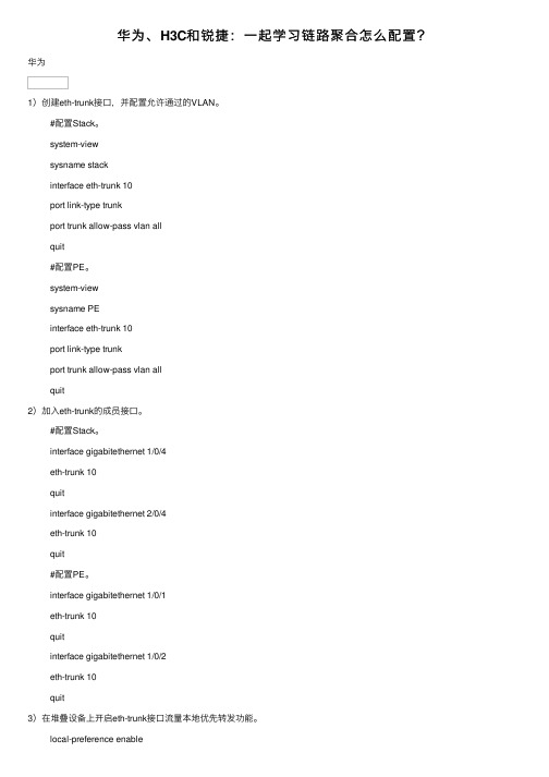
华为、H3C和锐捷:⼀起学习链路聚合怎么配置?华为1)创建eth-trunk接⼝,并配置允许通过的VLAN。
#配置Stack。
system-viewsysname stackinterface eth-trunk 10port link-type trunkport trunk allow-pass vlan allquit#配置PE。
system-viewsysname PEinterface eth-trunk 10port link-type trunkport trunk allow-pass vlan allquit2)加⼊eth-trunk的成员接⼝。
#配置Stack。
interface gigabitethernet 1/0/4eth-trunk 10quitinterface gigabitethernet 2/0/4eth-trunk 10quit#配置PE。
interface gigabitethernet 1/0/1eth-trunk 10quitinterface gigabitethernet 1/0/2eth-trunk 10quit3)在堆叠设备上开启eth-trunk接⼝流量本地优先转发功能。
local-preference enableinterface eth-trunk 10local-preference enablequit4)配置⼆层转发功能。
#配置Stack。
vlan batch 2 3interface gigabitethernet 1/0/3port link-type trunkport trunk allow-pass vlan 2quitinterface gigabitethernet 2/0/3port link-type trunkport trunk allow-pass vlan 3quit#配置Switch1。
system-viewsysname switch1vlan 2quitinterface gigabitethernet 0/0/1port link-type trunkport trunk allow-pass vlan 2quitinterface gigabitethernet 0/0/2port link-type trunkport trunk allow-pass vlan 2quit#配置Switch2。
3、思科模拟器链路聚合命令hao
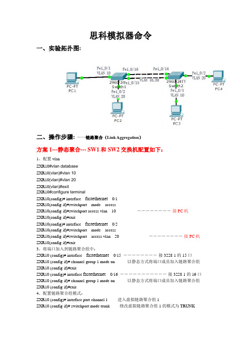
思科模拟器命令一、实验拓扑图:二、操作步骤:——链路聚合(Link Aggregation)方案1---静态聚合--- SW1和SW2交换机配置如下:1、配置vlanZXR10#vlan databaseZXR10(vlan)#vlan 10ZXR10(vlan)#vlan 20ZXR10(vlan)#exitZXR10#configure terminalZXR10(config)# interface fastethernet0/1ZXR10(config-if)#switchport mode accessZXR10(config-if)#switchport access vlan 10 ――――――――-接PC机ZXR10(config-if)#exitZXR10(config)# interface fastethernet0/2ZXR10(config-if)#switchport mode accessZXR10(config-if)#switchport access vlan 20 ――――――――-接PC机ZXR10(config-if)#exit3、将端口加入到链路聚合组中:ZXR10 (config)# interface fastethernet 0/15 ――――――――-接3228-1的15口ZXR10 (config-if)# channel-group 1 mode on---------以静态方式将端口成员加入链路聚合组ZXR10 (config-if)#exitZXR10 (config)# interface fastethernet 0/16 ―――――――――――-接3228-1的16口ZXR10 (config-if)# channel-group 1 mode on---------以静态方式将端口成员加入链路聚合组ZXR10 (config-if)#exit4、配置链路聚合组模式:ZXR10 (config)# interface port-channel 1-------进入虚拟链路聚合组1ZXR10 (config-if)# switchport mode trunk-------修改虚拟链路聚合组1的模式为TRUNKZXR10(config-if)#switchport trunk allowed vlan 10,20----虚拟链路聚合组1承载VLAN 10,20 ZXR10 (config)#exit(SW2交换机配置同SW-1一样)方案2 –动态链路聚合---SW1和SW2交换机配置如下:1、配置vlanZXR10#vlan databaseZXR10(vlan)#vlan 10ZXR10(vlan)#vlan 20ZXR10(vlan)#exitZXR10#configure terminalZXR10(config)# interface fastethernet0/1ZXR10(config-if)#switchport mode accessZXR10(config-if)#switchport access vlan 10 ――――――――-接PC机ZXR10(config-if)#exitZXR10(config)# interface fastethernet0/2ZXR10(config-if)#switchport mode accessZXR10(config-if)#switchport access vlan 20 ――――――――-接PC机ZXR10(config-if)#exit3、将端口加入到链路聚合组中:ZXR10 (config)# interface fastethernet 0/15 ――――――――-接3228-1的15口ZXR10 (config-if)# channel-protocol lacp--------设置端口聚合模式为动态模式ZXR10 (config-if)# channel-group 1 mode active(/passive)---------以动态方式将端口成员加入链路聚合组ZXR10 (config-if)#exitZXR10 (config)# interface fastethernet 0/16 ―――――――――――-接3228-1的16口ZXR10 (config-if)# channel-protocol lacp--------设置端口聚合模式为动态模式ZXR10 (config-if)# channel-group 1 mode active(/passive)---------以动态方式将端口成员加入ZXR10 (config-if)#exit4、配置链路聚合组模式:ZXR10 (config)# interface port-channel 1ZXR10 (config-if)# switchport mode trunkZXR10(config-if)#switchport trunk allowed vlan 10,20ZXR10 (config)#exit(SW2交换机配置同SW-1一样)注:聚合模式设置为on时端口运行静态trunk,参与聚合的两端都需要设置为on模式。
链路聚合原理配置实例
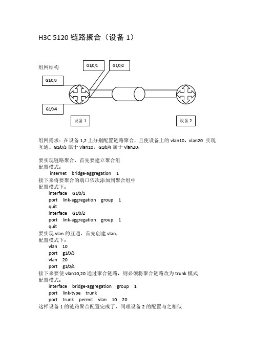
组网需求:在设备1,2上分别配置链路聚合,且使设备上的vlan10,vlan20 实现互通。
G1/0/3属于vlan10,G1/0/4属于vlan20;要实现链路聚合,首先要建立聚合组配置模式:internet bridge-aggregation 1接下来将要聚合的端口依次添加到聚合组中配置模式下:interface G1/0/1port link-aggregation group 1quitinterface G1/0/2port link-aggregation group 1quit要实现vlan的互通,首先创建vlan,配置模式下:vlan 10port g1/0/3vlan 20port g1/0/4接下来要使vlan10,20通过聚合链路,则必须将聚合链路改为trunk模式配置模式:interface bridge-aggregation group 1port link-type trunkport trunk permit vlan 10 20这样设备1的链路聚合配置完成了,同理设备2的配置与之相似组网需求:在设备1,2上分别配置链路聚合,且使设备上的vlan10,vlan20 实现互通。
G1/0/3属于vlan10,G1/0/4属于vlan20;要实现链路聚合,首先要建立聚合组配置模式:Link-aggregation group 1 mode manual接下来将要聚合的端口依次添加到聚合组中配置模式下:interface G1/0/1port link-aggregation group 1port link-type trunkport trunk permit vlan 10 20quitinterface G1/0/2port link-aggregation group 1port link-type trunkport trunk permit vlan 10 20quit要实现vlan的互通,首先创建vlan,配置模式下:vlan 10port g1/0/3vlan 20port g1/0/4这样实现互通后的聚合链路,协商速率为200Mbps/s(5120为千兆,36为百兆)。
windows服务器双网卡链路聚合

windows服务器双网卡链路聚合
1、重命名网卡名
win10左下角LOGO->设置->网络和internet->(左侧)以太网->(右侧)网络和共享中心->(左侧)更改适配器设置,默认情况下两个网卡名称改为“nic1”,“nic2”。
2、Power Shell
打开Win10的power shell使用命令行设置,在win10左下角LOGO输入powershell,右键点击“Windows PowerShell”,以管理员身份运行,会有弹出对话框,选择“是”。
3、命令行
在弹出的窗口中输入new-netLbfoteam “teamingname” -teamingmode switchindependent接下来会提示输入需要绑定的网卡名,如图:
4、效果
回到电脑的网络适配器,网卡已经绑定成功,此时原来的两个独立的网卡已经不见了,显示的是绑定的网卡聚合的名称,如图:
5、删除网卡聚合
若想恢复原来的网卡配置,可输入命令remove-netLbfoteam -name teamingname删除指定网卡组,get-netLbfoteam | remove-netLbfoteam删除所有网卡组。
标签:windows
分类:WIN系统
| 发布:wanglei | 评论:0条 | 发表时间:2020-1-15 9:01 Wednesday。
链路聚合配置

链路聚合配置(1)配置Device A# 创建VLAN 10和聚合接口1,并将该接口加入VLAN 10。
system-view[DeviceA] vlan 10[DeviceA-vlan10] quit[DeviceA] interface bridge-aggregation 1[DeviceA-Bridge-Aggregation1] port access vlan 10[DeviceA-Bridge-Aggregation1] quit# 分别将端口GE4/0/1至GE4/0/3加入到聚合组1和VLAN 10中。
[DeviceA] interface gigabitethernet 4/0/1[DeviceA-Gigabitethernet4/0/1] port link-aggregation group 1[DeviceA-Gigabitethernet4/0/1] port access vlan 10Warning:This port is a member of the link aggregation group. If configuration of the whole group is required to be modified, please configure it under the aggregation interface view. Otherwise, this operation may interrupt network traffic.Continue?[Y/N]: y[DeviceA-Gigabitethernet4/0/1] quit[DeviceA] interface gigabitethernet 4/0/2[DeviceA-Gigabitethernet4/0/2] port link-aggregation group 1[DeviceA-Gigabitethernet4/0/2] port access vlan 10Warning:This port is a member of the link aggregation group. If configuration of the whole group is required to be modified, please configure it under the aggregation interface view. Otherwise, this operation may interrupt networktraffic.Continue?[Y/N]: y[DeviceA-Gigabitethernet4/0/2] quit[DeviceA] interface gigabitethernet 4/0/3[DeviceA-Gigabitethernet4/0/3] port link-aggregation group 1[DeviceA-Gigabitethernet4/0/3] port access vlan 10Warning:This port is a member of the link aggregation group. If configuration of the whole group is required to be modified, please configure it under the aggregation interface view. Otherwise, this operation may interrupt network traffic.Continue?[Y/N]: y[DeviceA-Gigabitethernet4/0/3] quit# 配置全局聚合负载分担模式为源MAC地址与目的MAC地址相结合的方式。
PTC04OLT之10-链路聚合配置命令

-1-
参数
参数 id lacp-negotiation static
参数说明 逻辑端口的id号。取值范围:无。 使用LACP协商。取值范围:N/A。 端口不用协商。取值范围:N/A。
链路聚合配置命令
缺省
该端口没有被聚合
使用说明
端口链路聚合是将几个具有相同属性的端口捆绑为一个逻辑端口,而这个捆绑过程可以 通过 Lacp 协商,也可以不用通过协商而强制的捆绑到一起。
input errors 表示接收的有错的报文。
input discards 表示接收的报文被丢弃,如 Interface 协议 Down 时接收到的报文。
packets Output 表示所有的发送的报文,包括单播、组播、广播。 bytes 表示所有的发送报文的 byte 总量。 broadcasts 表示发送的广播报文。 multicasts 表示发送的组播报文。 input errors 表示发送出错的报文。 input discards 表示发送的报文被丢弃,如 Interface 协议 Down 时发送的报文。
Hardware is PortAggregator, Address is 0000.0000.0000(0000.0000.0000) MTU 1500 bytes, BW 1000 kbit, DLY 2000 usec Encapsulation ARPA, loopback not set Members in this Aggregator: 5 minute input rate 0 bits/sec, 0 packets/sec 5 minute output rate 0 bits/sec, 0 packets/sec
链路聚合配置命令
链路聚合配置命令
目录1 链路聚合配置命令................................................................................................................................ 1-11.1 链路聚合配置命令............................................................................................................................. 1-11.1.1 description .............................................................................................................................. 1-11.1.2 display lacp system-id ............................................................................................................ 1-21.1.3 display link-aggregation member-port.................................................................................... 1-21.1.4 display link-aggregation summary.......................................................................................... 1-41.1.5 display link-aggregation verbose............................................................................................ 1-51.1.6 enable snmp trap updown...................................................................................................... 1-71.1.7 interface bridge-aggregation .................................................................................................. 1-81.1.8 lacp port-priority...................................................................................................................... 1-81.1.9 lacp system-priority................................................................................................................. 1-91.1.10 link-aggregation mode........................................................................................................ 1-101.1.11 port link-aggregation group ................................................................................................ 1-101.1.12 reset lacp statistics............................................................................................................. 1-111.1.13 shutdown ............................................................................................................................ 1-111 链路聚合配置命令●本手册中提到的三层以太网接口是指已经被配置为路由模式的以太网端口,有关以太网端口模式切换的操作,请参见接入分册的“以太网端口”部分。
链路聚合(端口汇聚)配置

链路聚合(端口汇聚)配置Link aggregation (port pooling) configurationPort will converge is more than one Ethernet port group together to form a logical gathering, use pooling for upper entity to more than the physical link within the same group together as a logical link.The port aggregation enables the traffic to be Shared across member ports in the aggregation group to increase the bandwidth. At the same time, a dynamic backup of each member port of the same group increases the reliability of the connection.Based on the IEEE802.3 AD standard LACP (Link Aggregation Control Protocol, Link Aggregation Control Protocol) is a Protocol that implements the Link dynamic convergence and solution pooling. The LACP Protocol USES the LACPDU (Link Aggregation Control Protocol Data Unit, the Link Aggregation Control Protocol Data Unit) and the end-to-end interaction information.After the LACP protocol that starts a port, the port will notify the end of the system priority, system MAC, port priority, port number, and operation Key by sending the LACPDU. To end after received this information, the information compared to other port the saved information to choose the port to gather, thus both sides can be to the port to join or quit a dynamic group consensus.According to the convergence method, the port convergence can be divided into three categories: manual gathering, static LACPpooling, dynamic LACP pooling.Experimental environment: two H3C E126A, ethernet1/0/24, ethernet1/0/23 converge to a link.Manual together:Configuration of the first switch:[H3CA] link - aggregation group 10 mode manual[H3CA] interface Ethernet 1/0/24[h3ca-ethernet1/0/24] port link - aggregation group 10Can not specify a loopback - detection enable port as aggregation group member![h3ca-ethernet1/0/24] undo loopback - detection enable / / close the lookback-detection capability[h3ca-ethernet1/0/24] port link - aggregation group 10[H3CA Ethernet1/0/24][H3CA] interface ethernet1/0/23[h3ca-ethernet1/0/23] undo loopback - detection enable[h3ca-ethernet1/0/23] port link - aggregation group 10[H3CA Ethernet1/0/23]Configuration of the second switch:[H3CB] link - aggregation group 10 mode manual[H3CB] interface ethernet1/0/24[H3CB - Ethernet1/0/24] undo loopback - detection enable[H3CB - Ethernet1/0/24] port link - aggregation group 10[H3CB - ethernet1/0/24] interface ethernet1/0/23[H3CB - Ethernet1/0/23] undo loopback - detection enable[H3CB - Ethernet1/0/23] port link - aggregation group 10[H3CB Ethernet1/0/23]Display relevant information:[H3CB] display link - aggregation summary / / display summary informationAggregation Group Type -- Dynamic, S -- Static, M -- ManualLoadsharing Type: Shar -- Loadsharing, NonS -- non-loadsharingActor ID: 0x8000, 000f-e2a8-2defAL AL Partner ID Select Unselect Share MasterID Type Ports Ports Type Port-- -- -- -- -- -- -- -- -- -- -- -- -- -- -- -- -- -- -- -- -- -- -- -- -- -- -- -- -- -- -- -- -- -- -- -- -- -- -- -- -- -- -- -- -- -- -- -- -- -- -- -- -- -- -- -- -- -- -- -- -- -- -- -- -- -- -- -- -- -- -- -- -- -- -- -- -- -- -- --10 M none 2 0 Shar Ethernet1/0/23[H3CB][H3CB] display link - aggregation interface ethernet1/0/24 / display interface informationEthernet1/0/24:Selected AggID: 10Local:Port - Priority: 32768, Oper key: 1, Flag: 0x00远程:系统ID:0 x0,0000-0000-0000端口:0,端口优先级:0,操作键:0,标志:0x00[H3CB]显示ethernet1/0/23链路聚合接口Ethernet1/0/23:选择AggID:10的地方:端口优先:32768,主键:1,标记:0x00远程:系统ID:0 x0,0000-0000-0000端口:0,端口优先级:0,操作键:0,标志:0x00(H3CB)[H3CB]显示链路聚合详细/ /显示详细信息Loadsharing类型:Shar——负载共享、NonS——非负载共享标记:A——LACP_Activity,B——LACP_timeout,C——聚合,D——同步,E——收集,F——分布,拖欠,H,过期了聚合ID:10,聚合类型:手动,Loadsharing类型:Shar聚合描述:系统ID:000 0 x8000 f-e2a8-2def端口状态:S——选择,U——未选中的地方:端口状态优先级主标志- - - - - - - - - - - - - - - - - - - - - - - - - - - - - - - - - - - - - - - - - - - - - - - - - - - - - - - - - - - - - - - - - - - - - - - - - - - - - - - - -Ethernet1/0/23 S 32768 1 { }Ethernet1/0/24 S 32768 1 { }远程:演员合作伙伴优先级关键系统Flag- - - - - - - - - - - - - - - - - - - - - - - - - - - - - - - - - - - - - - - - - - - - - - - - - - - - - - - - - - - - - - - - - - - - - - - - - - - - - - - - -Ethernet1/0/23 0 0 0x0000,000000000000 { }以太网1 / 24 0 0 0 0x0000,000000000000 { }(H3CB)LACP静态配置及显示信息:[H3CA]链接聚合组10模式静态ethernet1/0/24(H3CA)接口(H3CA-Ethernet1/0/24)端口链路聚合组10不能指定环回检测启用端口作为聚合组成员!(H3CA-Ethernet1/0/24)撤销loopback-detection启用(H3CA-Ethernet1/0/24)端口链路聚合组10:1 - lacp是不允许的端口以太网的远程端ethernet1/0/23(H3CA-Ethernet1/0/24)接口(H3CA-Ethernet1/0/23)撤销loopback-detection启用(H3CA-Ethernet1/0/23)端口链路聚合组10(H3CA-Ethernet1/0/23):1 - lacp是不允许的端口ethernet1/0 / 23的远程端。
链路聚合(端口汇聚)配置
手工汇聚:
第一台交换机的配置:
[H3CA]link-aggregation group 10 mode manual
[H3CA]interface ethernet 1/0/24
[H3CA]interface ethernet1/0/24
[H3CA-Ethernet1/0/24]port link-aggregation group 10
Can not specify a loopback-detection enable port as aggregation group member !
D -- Synchronization, E -- Collecting, F -- Distributing,
G -- Defaulted, H -- Expired
Aggregation ID: 10, AggregationType: Manual, Loadsharing Type: Shar
[H3CA-Ethernet1/0/24]undo loopback-detection enable
[H3CA-Ethernet1/0/24]port link-aggregation group 10
%Apr 1 23:58:48:162 2000 H3CA LAGG/3/PartnerNoLacp:- 1 -LACP is not enabled on
启动某端口的LACP协议后,该端口将通过发送LACPDU向对端通告自己的系统优先级、系统MAC、端口优先级、端口号和操作Key。对端接收到这些信息后,将这些信息与其它端口所保存的信息比较以选择能够汇聚的端口,从而双方可以对端口加入或退出某个动态汇聚组达成一致。
华为链路聚合2种模式配置
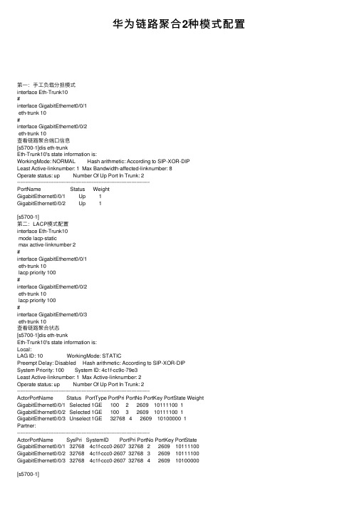
华为链路聚合2种模式配置第⼀:⼿⼯负载分担模式interface Eth-Trunk10#interface GigabitEthernet0/0/1eth-trunk 10#interface GigabitEthernet0/0/2eth-trunk 10查看链路聚合端⼝信息[s5700-1]dis eth-trunkEth-Trunk10's state information is:WorkingMode: NORMAL Hash arithmetic: According to SIP-XOR-DIPLeast Active-linknumber: 1 Max Bandwidth-affected-linknumber: 8Operate status: up Number Of Up Port In Trunk: 2--------------------------------------------------------------------------------PortName Status WeightGigabitEthernet0/0/1 Up 1GigabitEthernet0/0/2 Up 1[s5700-1]第⼆:LACP模式配置interface Eth-Trunk10mode lacp-staticmax active-linknumber 2#interface GigabitEthernet0/0/1eth-trunk 10lacp priority 100#interface GigabitEthernet0/0/2eth-trunk 10lacp priority 100#interface GigabitEthernet0/0/3eth-trunk 10查看链路聚合状态[s5700-1]dis eth-trunkEth-Trunk10's state information is:Local:LAG ID: 10 WorkingMode: STATICPreempt Delay: Disabled Hash arithmetic: According to SIP-XOR-DIPSystem Priority: 100 System ID: 4c1f-cc9c-79e3Least Active-linknumber: 1 Max Active-linknumber: 2Operate status: up Number Of Up Port In Trunk: 2--------------------------------------------------------------------------------ActorPortName Status PortType PortPri PortNo PortKey PortState Weight GigabitEthernet0/0/1 Selected 1GE 100 2 2609 10111100 1GigabitEthernet0/0/2 Selected 1GE 100 3 2609 10111100 1GigabitEthernet0/0/3 Unselect 1GE 32768 4 2609 10100000 1Partner:--------------------------------------------------------------------------------ActorPortName SysPri SystemID PortPri PortNo PortKey PortState GigabitEthernet0/0/1 32768 4c1f-ccc0-2607 32768 2 2609 10111100 GigabitEthernet0/0/2 32768 4c1f-ccc0-2607 32768 3 2609 10111100 GigabitEthernet0/0/3 32768 4c1f-ccc0-2607 32768 4 2609 10100000[s5700-1]第三:LACP模式,不配置优先级interface Eth-Trunk10mode lacp-static#interface GigabitEthernet0/0/1eth-trunk 10#interface GigabitEthernet0/0/2eth-trunk 10#查看链路聚合信息[Huawei]dis eth-trunkEth-Trunk10's state information is:Local:LAG ID: 10 WorkingMode: STATICPreempt Delay: Disabled Hash arithmetic: According to SIP-XOR-DIP System Priority: 32768 System ID: 4c1f-ccd9-7698Least Active-linknumber: 1 Max Active-linknumber: 8Operate status: up Number Of Up Port In Trunk: 2--------------------------------------------------------------------------------ActorPortName Status PortType PortPri PortNo PortKey PortState Weight GigabitEthernet0/0/1 Selected 1GE 32768 2 2609 10111100 1 GigabitEthernet0/0/2 Selected 1GE 32768 3 2609 10111100 1 Partner:--------------------------------------------------------------------------------ActorPortName SysPri SystemID PortPri PortNo PortKey PortState GigabitEthernet0/0/1 32768 4c1f-cc16-3faa 32768 2 2609 10111100 GigabitEthernet0/0/2 32768 4c1f-cc16-3faa 32768 3 2609 10111100 [Huawei]。
中兴设备实现链路聚合的配置

任务二:中兴设备实现链路聚合一、目的掌握交换机的链路静态聚合和动态聚合的配置和使用二、内容静态聚合和动态聚合的配置三、设备3228 两台直连网线两条串口线一条四、拓扑交换机3228-1 和交换机3228-2 通过smartgroup 端口相连,它们分别由2个物理端口聚合而成。
smartgroup 的端口模式为trunk,承载VLAN10 和VLAN20。
五、配置步骤1、静态聚合下面以3228-1 为例进行配置说明:/*关于VLAN 的部分自己完成*//*创建Trunk 组*/ZXR10(config)#interface smartgroup1 【创建smartgroup 端口,它有两个物理端口汇聚而成】ZXR10(config-if)#smartgroup mode on/*绑定端口到Trunk 组*/ZXR10(config)#interface fei_1/1ZXR10(config-if)#smartgroup 1 mode on //设置聚合模式为静态【设为静态的,两台交换机也都必须都设为静态的‘ON’】ZXR10(config)#interface fei_1/2ZXR10(config-if)#smartgroup 1 mode on【将端口FE-1/1 和FE-1/2 设置为聚合端口放置在smartgroup 1 并以静态方式工作】/*修改smartgroup 端口的VLAN 链路类型*/ZXR10(config)#interface smartgroup1ZXR10(config-if)#switchport mode trunkZXR10(config-if)#switchport trunk vlan 10 //把smartgroup1 端口以trunk 方式加入vlan10 ZXR(config-if)#switchport trunk vlan 20 //把smartgroup1 端口以trunk 方式加入vlan102、动态聚合下面以3228-1 为例进行配置说明:/*创建Trunk 组*/ZXR10(config)#interface smartgroup1ZXR10(config-if)#smartgroup mode 802.3ad/*绑定端口到Trunk 组*/ZXR10(config)#interface fei_1/1ZXR10(config-if)#smartgroup 1 mode active //设置聚合模式为active【配置动态链路聚合时,应当将一端端口的聚合模式设置为active,另一端设置为passive,或者两端都设置为active。
H3C配置命令10-端口汇聚命令
1.1.2 display link-aggregation interface
【命令】 display link-aggregation interface interface-type interface-number [ to interface-type interface-number ]
AL AL Partner ID
Select Standby Share Master
ID Type
Ports Ports Type Port
-------------------------------------------------------------------
1 D 0x8000, 000f-e20f-ff01 1
【举例】 # 显示汇聚组的摘要信息。
<H3C> display link-aggregation summary Aggregation Group Type: D -- Dynamic, S -- Static, M -- Manual
Loadsharing Type: Shar – Loadsharing, NonS – Non-Loadsharing Actor ID: 0x8000, 000f-e20f-ff04
H3C S7500 系列以太网交换机 命令手册 端口汇聚
目录
目录
第 1 章 端口汇聚配置命令 .......................................................................................................1-1 1.1 端口汇聚配置命令 .............................................................................................................. 1-1 1.1.1 display lacp system-id ............................................................................................. 1-1 1.1.2 display link-aggregation interface............................................................................ 1-1 1.1.3 display link-aggregation summary........................................................................... 1-3 1.1.4 display link-aggregation verbose............................................................................. 1-4 1.1.5 lacp enable .............................................................................................................. 1-5 1.1.6 lacp port-priority....................................................................................................... 1-6 1.1.7 lacp system-priority ................................................................................................. 1-6 1.1.8 link-aggregation....................................................................................................... 1-7 1.1.9 link-aggregation group description .......................................................................... 1-8 1.1.10 link-aggregation group mode ................................................................................ 1-8 1.1.11 port link-aggregation group ................................................................................... 1-9 1.1.12 reset lacp statistics ................................................................................................ 1-9
中兴设备实现链路聚合的配置
任务二:中兴设备实现链路聚合一、目的掌握交换机的链路静态聚合和动态聚合的配置和使用二、内容静态聚合和动态聚合的配置三、设备3228 两台直连网线两条串口线一条四、拓扑交换机3228-1 和交换机3228-2 通过smartgroup 端口相连,它们分别由2个物理端口聚合而成。
smartgroup 的端口模式为trunk,承载VLAN10 和VLAN20。
五、配置步骤1、静态聚合下面以3228-1 为例进行配置说明:/*关于VLAN 的部分自己完成*//*创建Trunk 组*/ZXR10(config)#interface smartgroup1 【创建smartgroup 端口,它有两个物理端口汇聚而成】ZXR10(config-if)#smartgroup mode on/*绑定端口到Trunk 组*/ZXR10(config)#interface fei_1/1ZXR10(config-if)#smartgroup 1 mode on //设置聚合模式为静态【设为静态的,两台交换机也都必须都设为静态的‘ON’】ZXR10(config)#interface fei_1/2ZXR10(config-if)#smartgroup 1 mode on【将端口FE-1/1 和FE-1/2 设置为聚合端口放置在smartgroup 1 并以静态方式工作】/*修改smartgroup 端口的VLAN 链路类型*/ZXR10(config)#interface smartgroup1ZXR10(config-if)#switchport mode trunkZXR10(config-if)#switchport trunk vlan 10 //把smartgroup1 端口以trunk 方式加入vlan10 ZXR(config-if)#switchport trunk vlan 20 //把smartgroup1 端口以trunk 方式加入vlan102、动态聚合下面以3228-1 为例进行配置说明:/*创建Trunk 组*/ZXR10(config)#interface smartgroup1ZXR10(config-if)#smartgroup mode 802.3ad/*绑定端口到Trunk 组*/ZXR10(config)#interface fei_1/1ZXR10(config-if)#smartgroup 1 mode active //设置聚合模式为active【配置动态链路聚合时,应当将一端端口的聚合模式设置为active,另一端设置为passive,或者两端都设置为active。
链路聚合配置
目录1 链路聚合配置 ....................................................................................................................................... 1-11.1 链路聚合简介.................................................................................................................................... 1-11.1.1 链路聚合的作用...................................................................................................................... 1-11.1.2 链路聚合的基本概念 .............................................................................................................. 1-11.1.3 链路聚合的模式...................................................................................................................... 1-31.1.4 聚合组的负载分担类型........................................................................................................... 1-41.2 配置静态聚合组 ................................................................................................................................ 1-51.3 配置动态聚合组 ................................................................................................................................ 1-61.4 聚合接口基本配置............................................................................................................................. 1-81.4.1 配置聚合接口描述信息........................................................................................................... 1-81.4.2 配置三层聚合接口/三层聚合子接口的最大传输单元MTU ..................................................... 1-91.4.3 开启聚合接口链路状态变化Trap功能................................................................................... 1-91.4.4 关闭聚合接口 ....................................................................................................................... 1-101.5 配置聚合负载分担模式 ................................................................................................................... 1-101.6 链路聚合显示与维护....................................................................................................................... 1-111.7 链路聚合典型配置举例 ................................................................................................................... 1-111.7.1 二层静态聚合配置举例......................................................................................................... 1-111.7.2 二层动态聚合配置举例......................................................................................................... 1-121.7.3 二层聚合负载分担模式配置举例 .......................................................................................... 1-131.7.4 三层静态聚合配置举例......................................................................................................... 1-141.7.5 三层动态聚合配置举例......................................................................................................... 1-151.7.6 三层聚合负载分担模式配置举例 .......................................................................................... 1-16本文中标有“请以实际情况为准”的特性描述,表示各型号对于此特性的支持情况可能不同,本节将对此进行说明。
链路聚合配置

(1)配置Device A# 创建VLAN 10和聚合接口1,并将该接口加入VLAN 10。
<DeviceA> system-view[DeviceA] vlan 10[DeviceA-vlan10] quit[DeviceA] interface bridge-aggregation 1[DeviceA-Bridge-Aggregation1] port access vlan 10[DeviceA-Bridge-Aggregation1] quit# 分别将端口GE4/0/1至GE4/0/3加入到聚合组1和VLAN 10中。
[DeviceA] interface gigabitethernet 4/0/1[DeviceA-Gigabitethernet4/0/1] port link-aggregation group 1[DeviceA-Gigabitethernet4/0/1] port access vlan 10Warning:This port is a member of the link aggregation group. If configuration of the whole group is required to be modified, please configure it under the aggregation interface view. Otherwise, this operation may interrupt network traffic.Continue?[Y/N]: y[DeviceA-Gigabitethernet4/0/1] quit[DeviceA] interface gigabitethernet 4/0/2[DeviceA-Gigabitethernet4/0/2] port link-aggregation group 1[DeviceA-Gigabitethernet4/0/2] port access vlan 10Warning:This port is a member of the link aggregation group. If configuration of the whole group is required to be modified, please configure it under the aggregation interface view. Otherwise, this operation may interrupt network traffic.Continue?[Y/N]: y[DeviceA-Gigabitethernet4/0/2] quit[DeviceA] interface gigabitethernet 4/0/3[DeviceA-Gigabitethernet4/0/3] port link-aggregation group 1[DeviceA-Gigabitethernet4/0/3] port access vlan 10Warning:This port is a member of the link aggregation group. If configuration of the whole group is required to be modified, please configure it under the aggregation interface view. Otherwise, this operation may interrupt network traffic.Continue?[Y/N]: y[DeviceA-Gigabitethernet4/0/3] quit# 配置全局聚合负载分担模式为源MAC地址与目的MAC地址相结合的方式。
路由器高级知识及配置(链路聚合配置)

B(config-gei_3/6)# smartgroup 11 mode passive
A(config-gei_5/2)# exit
B(config-gei_3/6)# exit
A(config)# interface gei_5/3
B(config)# interface gei_3/7
A(config-gei_5/3)# smartgrou路聚合配置实例
链路聚合配置实例
交换机A和交换机B通过smartgroup端口相连, 它们分别由4个物理端口聚合而成。 smartgroup的端口模式为trunk,承载VLAN10和VLAN20。
链路聚合配置实例
SwitchA配置
SwitchB配置
A(config)# interface smartgroup10
进入二层接口
ZXR10(config)#interface < interface-name>
绑定端口到Trunk组,并设置端口聚合模式
ZXR10(config-gei_1/x )# smartgroup <smartgroup-id> mode {passive|active|on}
聚合模式设置为on时端口运行静态trunk,参与聚合的两端都需要设 置为on模式。 聚合模式设置为active或passive时端口运行LACP,active指端口为主 动协商模式,passive指端口为被动协商模式 。
RX
Mux
Port State Interval
Priority Key State
Machine Machine
------------------------------------------------------------------------------
华为交换机链路聚合命令

华为交换机链路聚合命令一、华为交换机链路聚合概述链路聚合(Link Aggregation,LAG)是指将多个物理端口绑定成一个逻辑端口,从而提高带宽和可靠性。
华为交换机支持静态链路聚合和动态链路聚合两种方式。
静态链路聚合需要手动配置,适用于网络拓扑结构比较简单的场景;动态链路聚合则由协议自动完成,适用于网络拓扑结构比较复杂的场景。
二、华为交换机静态链路聚合命令1. 创建静态链路聚合组创建静态链路聚合组需要指定组号和模式(标准模式或LACP模式),示例命令如下:[huawei] interface Eth-Trunk 1[huawei-Eth-Trunk1] mode lacp2. 添加物理接口到静态链路聚合组添加物理接口到静态链路聚合组需要指定组号和物理接口编号,示例命令如下:[huawei] interface GigabitEthernet 0/0/1[huawei-GigabitEthernet0/0/1] eth-trunk 13. 配置静态链路聚合组的基本属性配置静态链路聚合组的基本属性包括:最大帧长、端口优先级、链路聚合组的描述等,示例命令如下:[huawei] interface Eth-Trunk 1[huawei-Eth-Trunk1] description trunk-group-1[huawei-Eth-Trunk1] port link-type trunk[huawei-Eth-Trunk1] port max-frame-length 9216[huawei-Eth-Trunk1] port priority 644. 配置静态链路聚合组的负载均衡方式配置静态链路聚合组的负载均衡方式包括:源MAC地址、目的MAC 地址、源IP地址、目的IP地址等,示例命令如下:[huawei] interface Eth-Trunk 1[huawei-Eth-Trunk1] load-balance dst-ip5. 查看静态链路聚合组信息查看静态链路聚合组信息可以使用display interface eth-trunk命令,示例如下:[huawei] display interface eth-trunk 1Eth-Trunk1 current state : UPLine protocol current state : UPDescription: trunk-group-1Route Port,The Maximum Transmit Unit is 9216, Hold timer is10(sec)Internet Address is not setLink layer protocol is IEEE 802.3adLoad sharing method: destination IP address-based(Hash) Member port:GigabitEthernet0/0/1 GigabitEthernet0/0/2 GigabitEthernet0/0/3三、华为交换机动态链路聚合命令动态链路聚合需要使用LACP协议,在华为交换机上的配置命令如下:1. 开启LACP协议开启LACP协议需要在接口上配置,示例命令如下:[huawei] interface GigabitEthernet 0/0/1[huawei-GigabitEthernet0/0/1] lacp enable2. 配置LACP协议的基本属性配置LACP协议的基本属性包括:端口优先级、系统优先级等,示例命令如下:[huawei] interface GigabitEthernet 0/0/1[huawei-GigabitEthernet0/0/1] lacp priority 1003. 查看动态链路聚合信息查看动态链路聚合信息可以使用display lacp命令,示例如下:[huawei] display lacpGlobal LACPDUs: Sent 22, Received 19Local System ID: 32768-00e0-fc00-0001System Priority: 32768Aggregation Mode: Link Aggregation Control Protocol (LACP) Actor Information:Actor System ID:32768-00e0-fc00-0001Actor Key:32769Actor Port Priority:32Actor Port Number:5Partner Information:Partner System ID:32768-0018-ba00-0002Partner Key:32769Partner Port Priority:255Partner Port Number:3四、华为交换机链路聚合常见问题及解决方法1. 静态链路聚合组无法建立可能原因:组号或模式设置错误;物理接口未添加到组中。
- 1、下载文档前请自行甄别文档内容的完整性,平台不提供额外的编辑、内容补充、找答案等附加服务。
- 2、"仅部分预览"的文档,不可在线预览部分如存在完整性等问题,可反馈申请退款(可完整预览的文档不适用该条件!)。
- 3、如文档侵犯您的权益,请联系客服反馈,我们会尽快为您处理(人工客服工作时间:9:00-18:30)。
-1-
参数
链路聚合配置命令
参数 id lacp-negotiation static
参数说明 逻辑端口的id号。取值范围:无。 使用LACP协商。取值范围:N/A。 端口不用协商。取值范围:N/A。
缺省
该端口没有被聚合
使用说明
端口链路聚合是将几个具有相同属性的端口捆绑为一个逻辑端口,而这个捆绑过程可以 通过 Lacp 协商,也可以不用通过协商而强制的捆绑到一起。
无
命令模式
全局配置模式
示例
下面的命令将创建聚合端口逻辑通道 1。 OLT_config# interface port-aggregator 1
1.1.2 aggregator-group
命令描述
aggregator-group id mode {lacp-negotiation |static } no aggregator-group 配置端口聚合,no 命令恢复到默认值。
-2-
配置端口聚合后的流量平衡,no 恢复到默认值。
链路聚合配置命令
参数
参数 dst-mac src-mac both-mac dst-ip src-ip both-ip
缺省
参数说明 以目的mac地址为标准。取值范围:N/A。 以源mac地址为标准。取值范围:N/A。 以源和目的mac地址为标准。取值范围:N/A。 以目的ip地址为标准。取值范围:N/A。 以源ip地址为标准。取值范围:N/A。 以源和目的ip地址为标准。取值范围:N/A。
命令模式
全局配置模式
示例
下面的命令将更改 port-aggregator 3 的流量平衡为 src 模式。 Switch(config)#port-aggregator load-balance 3 src-mac Switch(config)#
1.1.4 show aggregator-port
命令描述 show aggregator-port [id] {detail|brief|summary} 这条命令用来显示 aggregator-group 的具体信息。
0 packets input, 0 bytes, 0 no buffer Received 0 broadcasts, 0 multicasts 0 input errors, 0 input discards 0 CRC, 0 frame, 0 overrun, 0 ignored 0 packets output, 0 bytes, 0 underruns Transmited 0 broadcasts, 0 multicasts 0 output errors, , 0 discards 0 output buffer failures, 0 output buffers swapped out 说明: Members in this Aggregator,表示聚合到逻辑端口的物理端口。
参数
参数 id
参数说明 具体的端口id。取值范围:1-6。
缺省
无
说明
显示端口聚合信息。
命令模式
管理配置模式
链路聚合配置命令 -4-
示例
链路聚合配置命令
显示聚合端口 1 的信息。 Switch#sho int po1 Port-aggregator1 is down, line protocol is down
-I-
链路聚合配置命令
第 1 章 配置端口聚合命令
1.1 配置端口聚合命令
1.1.1 interface port-aggregator
命令描述
[no] interface port-aggregator id 配置聚合端口逻辑通道。
参数
参数 id
参数说明 逻辑端口的id号。取值范围:1~32。
缺省
链路聚合配置命令
目录
目录
第 1 章 配置端口聚合命令................................................................................................................................1 1.1 配置端口聚合命令...............................................................................................................................1 1.1.1 interface port-aggregator................................................................................................................ 1 1.1.2 aggregator-group........................................................................................................................... 1 1.1.3 aggregator-group load-balance....................................................................................................... 2 1.1.4 show aggregator-port..................................................................................................................... 3 1.1.5 show interface port-aggregator........................................................................................................4 1.1.6 debug lacp errors........................................................................................................................... 6 1.1.7 debug lacp state............................................................................................................................ 6 1.1.8 debug lacp packet..........................................................................................................................7
统计值说明如下:
packets input 表示所有的报文输入,包括单播、组播、广播。
bytes 表示所有的报文的 byte 总量。
broadcasts 表示接收的广播报文。
multicasts 表示接收的组播报文。
input errors 表示接收的有错的报文。
input discards 表示接收的报文被丢弃,如 Interface 协议 Down 时接收到的报文。
Hardware is PortAggregator, Address is 0000.0000.0000(0000.0000.0000) MTU 1500 bytes, BW 1000 kbit, DLY 2000 usec Encapsulation ARPA, loopback not set Members in this Aggregator: 5 minute input rate 0 bits/sec, 0 packets/sec 5 minute output rate 0 bits/sec, 0 packets/sec
命令模式
上联口配置模式
示例
下面的命令将在 g0/1 和 g0/2 捆绑到逻辑端口 port-aggregator 3,并使用 LACP 协商。 Switch(config_g0/2)#aggregator-group 3 mode lacp-negotiation Switch(config_g0/2)#int g0/1 Switch(config_g0/1)#aggregator-group 3 mode lacp-negotiation
dst-mac
使用说明
端口聚合后为了保证每一个物理端口都可以达到流量平衡,需要在每一个物理端口上均 匀的分配数据流量,使用此配置可以达到该目的。
当选择 dst-mac 方式时分配数据流量以数据报文的目的 MAC 地址为标准,同一个 mac 地址只从某一个物理端口上发出。而 src-mac 则使用源 MAC 地址为标准。
-3-
参数
参数 id
具体的逻辑端口ID。
缺省
无
使用说明
显示端口聚合信息。
命令模式
管face port-aggregator
参数说明
命令描述
show interface port-aggregator id 这条命令用来显示 aggregator-group 的具体信息。
packets Output 表示所有的发送的报文,包括单播、组播、广播。 bytes 表示所有的发送报文的 byte 总量。 broadcasts 表示发送的广播报文。 multicasts 表示发送的组播报文。 input errors 表示发送出错的报文。 input discards 表示发送的报文被丢弃,如 Interface 协议 Down 时发送的报文。