6脚电源IC资料及代换
六脚电源芯片
六脚电源芯片六脚电源芯片是一种常用的电子元件,用于提供稳定的电压输出。
它可以通过六个针脚连接到电路中,以便控制电流和电压的输出。
在本文中,我们将介绍关于六脚电源芯片的一些基本知识和应用,并探讨其优点和局限性。
首先,让我们了解一下六脚电源芯片的基本结构和工作原理。
六脚电源芯片由几个关键部分组成,包括调节器、电流限制器、短路保护器和过热保护电路。
调节器主要负责将输入电压调整为所需要的输出电压,以满足电路的要求。
电流限制器用于限制电流的输出,以保护电路和电源芯片免受过载的损害。
短路保护器可以在电流过大时自动切断电源芯片的输出,以防止火灾和其他安全问题。
过热保护电路用于监测芯片的温度,并在温度过高时自动切断电源芯片的输出。
六脚电源芯片具有很多优点,使其成为广泛使用的电子元件之一。
其中一个优点是其小巧的尺寸和低功耗设计,这使得它非常适合在便携式设备和小型电子产品中使用。
另外,六脚电源芯片通常具有较高的效率,在能量转换过程中损耗较少的能量,这有助于延长电池寿命和节省能源。
此外,六脚电源芯片还提供了稳定和可靠的电压输出,有助于保护整个电路中的其他元件。
然而,六脚电源芯片也有一些局限性需要考虑。
首先,六脚电源芯片的输出电流通常有一定的限制,这意味着它可能无法满足某些高功率应用的需求。
此外,六脚电源芯片在使用过程中可能会产生一定的热量,可能需要额外的散热设计来保持芯片的正常运行。
最后,六脚电源芯片的价格相对较高,这可能会增加产品的成本。
六脚电源芯片的应用非常广泛,包括消费电子产品、通信设备、汽车电子和工业自动化等领域。
在消费电子产品中,六脚电源芯片通常用于手机、平板电脑、数码相机和便携式音频设备等设备中,用于提供电源支持。
而在汽车电子方面,六脚电源芯片则广泛应用于汽车电子系统中,如动力系统、照明系统和车载娱乐系统等。
此外,在工业自动化领域,六脚电源芯片常用于电力控制、医疗设备和测量仪器等设备中。
总的来说,六脚电源芯片是一种非常重要的电子元件,用于提供电源支持和稳定的电压输出。
液晶电源IC的代换资料 2
格式如下好了"
液晶品牌与型号 电源管理芯片型号与封装 可代换型号
qBENQ 71G+ 1200AP40 直插 1200AP10 1200AP60
AOC 712SI EA1532A贴片
三星型号忘记 DM0565R
203D6 NCP1203D60R2 NCP1203D60R2G和DAP8A 直接代换
DAP02ALSZ与SG6841S可以互换
1200AP40和1200AP60直接代换
P5S0765和DP104、DP704直接代换
DP804和DP904直接代换
2S0680和2S0880直接代换
美格WB9D7575PS5
清华同方 XP911WD7575PS
联想LXM -WL19AH LXM-WL19BH D7575PS(早期有的用:NCP1203D6)
联想LXM-17CH:1203D6
方正17寸:1203D6与LD7575PS
方正19寸:LD7575PS
BenQ: FP94VW FP73G FP71G+S FP71G+G FP71GX等都是用:1200AP40
TEA1507和TEA1533直接代换
LD7535兼容 SG6848 (6849) / SG5701 / SG5848 /LD7535 (7550) / OB2262 (2263) / OB2278(2279)RS2051
LD7575和NCP1203、NCP1200 OB2268 SG5841 LD7552 OB2269 OB2268 RS20429
CR6850兼容SG6848/6849/5701/5848,OB2262/2263,LD7550/7535.
电源IC的代换资料

电源IC的代换资料DAP8A\DAP7A\LD7575\203D6\203X6\200D6可以直接代换,203d6是16v工作电压,而7575是30v ,代用要改启动电阻,可以用1200AP40直接代用MOB2268,OB2269,DAP02,SG6841,SG5841DAP02\SG5841\2G6841可以直接代换1200AP40\1200AP60\1203P60\1203AP10可以直接代换DM0465\CM0565\DM0565代换{要改电路}TOP246Y\TOP247Y可以直接代换。
大家来整理一个液晶电源的电源管理芯片集吧"格式如下好了"液晶品牌与型号电源管理芯片型号与封装可代换型号BENQ 71G+ 1200AP40 直插1200AP10 1200AP60YAOC 712SI EA1532A贴片三星型号忘记DM0565R'优派型号忘记TOP245YN2LG型号忘记FAN7601飞利浦170s6 dap02alsz 贴片LG型号忘记FAN7601 可以用LAF0001代飞利浦170s6 dap02alsz=sg6841美格WB9D7575PS清华同方XP911WD7575PS联想LXM -WL19AH LXM-WL19BH D7575PS(早期有的用:NCP1203D6联想LXM-17CH:1203D62方正17寸:1203D6与LD7575PS方正19寸:LD7575PSBenQ: FP94VW FP73G FP71G+S FP71G+G FP71GX等都是用:1200AP40LG 22(南京同创):LAF001与STR W6252 。
LG 19寸:LAF001联想L193(福建-捷联代工):NCP1203D6PHILIPS 170S5FAN7601)PHILIPS 15寸(老产品):(FAN7601)LG型号忘记FAN7601 可以用LAF0001代其他我知道的常用型号有SG6841DZ 贴片很多机器上用到ZSG5841SZ 贴片用SG6841DZ可以代用,DAP8A 与203D6可代用还有LD7575可用203D6代用,只是1脚的对地电阻不同,LD7575是100K,203D6是24.1K,LP7552可用SG6841代用i203D6 NCP1203D60R2 NCP1203D60R2G和DAP8A 直接代换rDAP02ALSZ与SG6841S可以互换U1200AP40和1200AP60直接代换5S0765和DP104、DP704直接代换DP804和DP904直接代换Q2S0680和2S0880直接代换TEA1507和TEA1533直接代换LD7535兼容SG6848 (6849) / SG5701 / SG5848 /LD7535 (7550) / OB2262 (2263) / OB2278(2279)RS2051)LD7575和NCP1203、NCP1200 OB2268 SG5841 LD7552 OB2269 OB2268 RS2042.CR6853兼容OB2263,UCR6201兼容THX201,TFC718;CR6203兼容THX203,TFC718SCR6848兼容SG6848/6849/5701/5848,OB2262/2263,LD7550/7535.CR6842兼容SG6841/6842,OB2268/2269/2278/2279,LD7552CR6860兼容ACT30,CR6853兼容OB2263,CR6201兼容THX201,TFC718;CR6202兼容THX202,TFC719;CR6203兼容THX203,TFC718S.CR6848兼容SG6848/6849/5701/5848,OB2262/2263,LD7550/7535.CR6850(兼容SG6848/6849/5701/5848,OB2262/2263,LD7550/7535.CR6851(兼容SG6848/6849/5701/5848,OB2262/2263,LD7550/7535.CR6842(兼容SG6841/6842,OB2268/2269/2278/2279,LD7552.。
[技术资料]液晶电源管理芯片代换大全
![[技术资料]液晶电源管理芯片代换大全](https://img.taocdn.com/s3/m/edd58a35a200a6c30c22590102020740be1ecdb6.png)
[技术资料]液晶电源管理芯片代换大全[技术资料] 液晶电源管理芯片代换大全1200AP40 1200AP60、1203P60200D6、203D6 DAP8A 可互代203D6/1203P6 DAP8A2S0680 2S08803S0680 3S08805S0765 DP104、DP7048S0765C DP704加24V的稳压二极管ACT4060 ZA3020LV/MP1410/MP9141ACT4065 ZA3020/MP1580ACT4070 ZA3030/MP1583/MP1591MP1593/MP1430 ACT6311 LT1937ACT6906 LTC3406/AT1366/MP2104AMC2576 LM2576AMC2596 LM2596AMC3100 LTC3406/AT1366/MP2104AMC34063A AMC34063AMC7660 AJC1564AP8012 VIPer12AAP8022 VIPer22ADAP02 可用SG5841 /SG6841代换DAP02ALSZ SG6841DAP02ALSZ SG6841DAP7A、DP8A 203D6、1203P6DH321、DL321 Q100、DM0265RDM0465R DM/CM0565RDM0465R/DM0565R 用cm0565r代换(取掉4脚的稳压二极管)DP104 5S0765DP704 5S0765DP706 5S0765DP804 DP904FAN7601 LAF0001LD7552 可用SG6841代(改4脚电阻)LD7575PS 203D6改1脚100K电阻为24KOB2268CP OB2269CPOB2268CP SG6841改4脚100K电阻为20-47KOCP1451 TL1451/BA9741/SP9741/AP200OCP2150 LTC3406/AT1366/MP2104OCP2160 LTC3407OCP2576 LM2576OCP3601 MB3800OCP5001 TL5001OMC2596 LM2596/AP1501PT1301 RJ9266PT4101 AJC1648/MP3202PT4102 LT1937/AJC1896/AP1522/RJ9271/MP1540SG5841SZ SG6841DZ/SG6841DSM9621 RJ9621/AJC1642SP1937 LT1937/AJC1896/AP1522/RJ9271/MP1540STR-G5643D STR-G5653D、STR-G8653DTEA1507 TEA1533TEA1530 TEA1532对应引脚功能接入THX202H TFC719THX203H TFC718STOP246Y TOP247YVA7910 MAX1674/75 L6920 AJC1610VIPer12A VIPer22A[audio01]ICE2A165(1A/650V.31W);ICE2A265(2A/650V.52W);ICE2B0565(0.5A/650V.23W):ICE2B165(1A/650V.31W);ICE2B265(2A/650V.52W);ICE2A180(1A/800V.29W);ICE2A280(2A/800.50W).KA5H0365R, KA5M0365R, KA5L0365R, KA5M0365RN# u) t! u1 W1 B) R, PKA5L0365RN, KA5H0380R, KA5M0380R, KA5L0380R1、KA5Q1265RF/RT(大小两种体积)、KA5Q0765、FSCQ1265RT、KACQ1265RF、FSCQ0765RT、FSCQ1565Q这是一类的,这些型号的引脚功能全都一样,只是输出功率不一样。
VIPER-22A资料及原理图
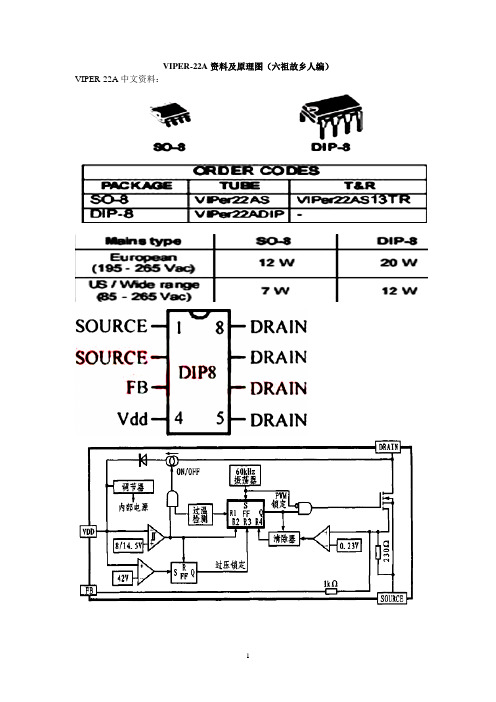
VIPER-22A资料及原理图(六祖故乡人编)VIPER-22A中文资料:(六祖故乡人编)HR500-2型万能表R×1kΩ档估测的内阻值:黑表笔(脚) 红表笔(脚)电阻(Ω)1、22、1 01、2 3 1.1k1、2 4 4。
4k1、2 5、6、7、8 3。
7k3 1、2 1。
1k3 4 6.1k3 5、6、7、8 5。
2k4 1、2 11k4 3 12.8k4 5、6、7、8 5k5、6、7、8 1、2 120k5、6、7、8 3 125k5、6、7、8 4 140k(六祖故乡人编)V IPER22A芯片概述:意法半导体的V IPER22A芯片为专用开关电源集成电路。
其内部结构如图1所示.芯片工作时,直流电压从漏极脚进入集成电路,经整流和稳压后供给开关电源工作,从而使这个电路工作时不需要外接启动电阻。
即使VDD供电电路不正常, 电源电路的振荡电路仍能起振,而且上图1 V IPER22A芯片内部结构电路有输出电压.在VDD正常前, 由芯片内部自身供电, 经过很短时间后, VDD供电电源正常,此时,利用门电路控制开关电路(ON /OFF)断开从栅极输入的供电回路.V IPER22A 有过热、过压保护功能。
VDD从4脚输入后,首先送入比较器,一旦输入VDD ≥42 V, 则触发器( FF1)输出一个置位信号1使控制振荡电路工作的触发器( FF2)输出为0,锁住U2 , 振荡信号无法输出,即开关管不工作。
当输入电压小于1415 V时, U3 也将输出一个复位脉冲,使开关管不工作。
当电路过热时, R1 为1,将FF2置0,开关管不工作。
当供电电压VDD 在正常范围时, FB所得的取样电压与基准电压0123 V相比较,用其比较结果去控制FF2 的转换频率,从而控制开关管的状态转换,实现控制输出电压,达稳压的功能。
该集成电路芯片内部包含60kHz的振荡电路,其外围电路相当简单。
3 V IPER22A开关电源电路本文所使用的V IPER22A芯片具有优良的控制功能,使得外围电路的设计较简单,只需考虑一般的短路、过载电路保护即可.电路原理图如图2。
常用开关电源芯片资料

常用开关电源芯片资料2011-10-14 08:49:00| 分类:【电子元件及应用 |字号大中小订阅一、P1014AP06 TNY267P 可以互换常用于电脑电源卫星接收机电源(NCP1010~1014) 1脚反馈供电 2378地 4脚光耦4脚 5脚开关变压器来电 6脚无此脚二、FSD200 FSD210 不能互换常用于接收机电源电磁炉电源8脚300V 7脚开关变压器来电端 6脚无此脚 5反馈供电 4脚光耦4脚 123脚光耦3脚与接地三、VIPer12A VIPer22A 能互换常用于电磁炉电源影碟机电源12地 3光耦3脚 4光耦4脚 5678开关变压器来电四、天诚数字卫星接收机DH321 1脚负 2脚正反馈供电 3光耦4脚 4电阻到负 5启动电阻 678正五、DVD VCD 开关电源5M02659R 0265 0380 1空 2地 3小电源 4光耦 5空 678电源TDA16833(1234) 1,3.6为空 2FB 45D 7VCC 8GND5M0265和5M02659R一样一台步步高VCD电源用的是5L0265,我用5L0380代用的.机子修好!!! 5L0380可以代换5L0265 5L0380代5M02659R 1=1(连通1和2电路) 2=7 3=3 4=4IM0280代换用IM0380代换8脚IC似乎是02659的引脚,用5L0380代换DM0265r应该是1=1,2=78,3=2,4=32A0165、2A0265、2A0565都可用5L0380R(四脚)代用,方法如下:5L0380R的1脚接2A0265的8脚, 2脚接4、5脚, 3脚接7脚, 4脚接2脚。
我用这个方法已修好了三、四十台,可靠又实用。
在有的机上,原机无启动电阻,你可在5L0380的3脚与300V间加一只120K/2W(180~300k)的电阻,不然就会不启动。
或者直接从交流引47K电阻DM0265可以用DM0365代替,其封装为8脚.1-地,2-13V.7,3-0.9V,4-1.0V,5,6,7,8脚电压值300V.电路外围的稳压2极管D6易出现软坏,最好替换用5L0380很好改,一脚接地,2脚接开关变压器300V,3脚反馈,4脚光偶.TDA16833TH203POWER-22A2人 | 分享到:阅读(3674)|评论(0)|转载(2)|举报。
8205S 6脚IC规格书
40
20 10
1ms
1
0.01S
0.1
0.03 0.1
VGS=4V Single Pulse TA=25 C
1
0.1S 1S DC
5 10 20 50
VDS , Drain-Source Voltage (V)
Figure 7. Maximum Safe Operating Area
Vin VGS RGEN
ID , Drain Current (A)
20 16 12 8 4 0
0 0.5 1 1.5 2.0 2.5 3.0
VGS , Gate-to-Source Voltage (V) Figure 2. Transfer Characteristics
2
1.75
VGS= 4V ID= 4.3A
1.5
8205GN
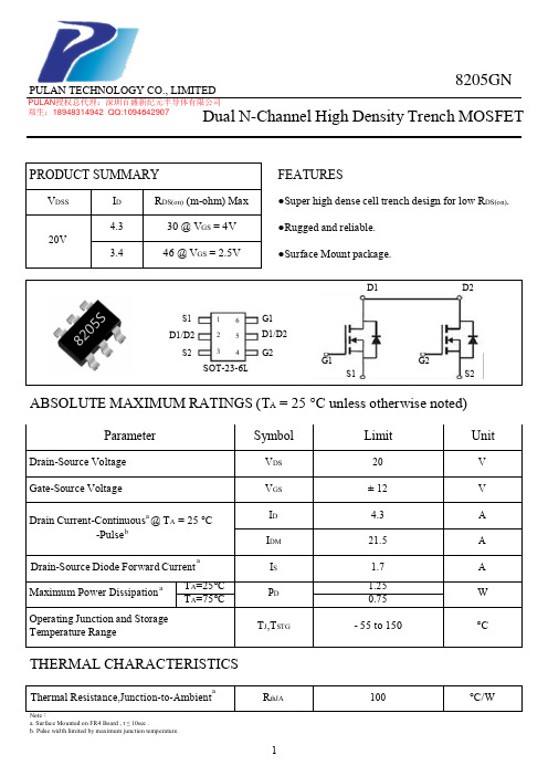
ELECTRICAL CHARACTERISTICS (TA = 25 °C unless otherwise noted)
Parameter
Symbol
Condition
Min Typc Max Unit
OFF CHARACTERISTICS
Drain-Source Breakdown Voltage
Note: a. Surface Mounted on FR4 Board , t ≤ 10sec . b. Pulse width limited by maximum junction temperature.
RthJA 1
100
°C/W
PULAN TECHNOLOGY CO., LIMITED
0.2
0.1 0.1 0.05
PDM
六脚电源芯片电路图

六脚电源芯片电路图
抱歉,我无法描绘电路图。
但是,我可以帮你解释一下六脚电源芯片的基本原理和功能。
也可以提供你一个六脚电源芯片的示例电路。
六脚电源芯片是一种集成电路,用于提供稳定和可靠的电源给其他电子设备。
它通常由多个功能组件组成,包括稳压器、开关、过温保护等。
六脚电源芯片主要用于DC-DC电源升压、降压和稳压的应用,可以将输入电源的电压转换为其他电子设备所需的合适电压。
以下是一个六脚电源芯片的示例电路图:
```
_______
| |
Vi ---| |
| |
GND --| |--- Vo
| IC |
En ---| |
|_______|
```
在这个示例电路中,Vi是输入电源的电压,Vo是输出电源的电压,GND是接地线,En是使能引脚。
当En引脚接收到高电平时,六脚电源芯片开始工作。
它会根据输入电源的电压和其他电路设置,将Vi转换为Vo,并稳定在指定的电压。
通常情况下,六脚电源芯片还会具备其他保护功能,如过电流保护、短路保护和过温保护等。
这些保护机制可以确保电源芯片和其他电子设备的安全运行。
需要注意的是,不同的六脚电源芯片可能具有不同的引脚布局和功能。
因此,在具体应用时,应该参考芯片的数据手册或技术规格书,以了解更多关于该芯片的特性和使用方法。
希望以上的信息对你有所帮助!如果还有任何疑问,请随时提问。
LCD电源芯片代换
S0765和DP104、DP704直接代换
DP804和DP904直接代换
2S0680和2S0880直接代换
TEA1507和TEA1533直接代换
DAP8A,DAP7A,LD7575,203D6,203X6,200D6可以直接代换
203d6是16v工作电压,而7575是30v ,代用要改启动电阻,
FAN7601与LAF0001可以直接代换
EA1532A可以用DAP8A
203D6代换 P1337要把一脚启动电阻由18k换成100k
OCP5001-TL5001直接代换
AMC3100-LTC3406/AT1366/直接代换
MP2104 OCP2150-LTC3406/直接代换
AT1366/MP2104 直接代换
DAP02可用SG5841 。SG6841代换: EA1530 EA1532
TOP246Y可用TOP247Y代
1200AP40和1200AP60直接换,我用1200AP40代过1203P605S0765和DP104、DP704、DP706直接代换
我用DP704代过8S0765C不过加了个24V的稳压二极管
LD7575和NCP1203、NCP1200 OB2268 SG5841 LD7552 OB2269 OB2268 RS2042
CR6860兼容ACT30,
CR6853兼容OB2263,
CR6201兼容THX201,TFC718;
CR6202兼容THX202,TFC719;
CR6203兼容THX203,TFC718S。
DP804和DP904直接代换
2S0680和2S0880直接代换
【VIP专享】电源芯片的代换

1200AP40 1200AP60、1203P60200D6、203D6 DAP8A 可互代203D6/1203P6 DAP8A2S0680 2S08803S0680 3S08805S0765 DP104、DP7048S0765C DP704加24V的稳压二极管ACT4060 ZA3020LV/MP1410/MP9141ACT4065 ZA3020/MP1580ACT4070 ZA3030/MP1583/MP1591MP1593/MP1430ACT6311 LT1937ACT6906 LTC3406/AT1366/MP2104AMC2576 LM2576AMC2596 LM2596AMC3100 LTC3406/AT1366/MP2104AMC34063A AMC34063AMC7660 AJC1564AP8012 VIPer12AAP8022 VIPer22ADAP02 可用SG5841 /SG6841代换DAP02ALSZ SG6841DAP02ALSZ SG6841DAP7A、DP8A 203D6、1203P6DH321、DL321 Q100、DM0265RDM0465R DM/CM0565RDM0465R/DM0565R 用cm0565r代换(取掉4脚的稳压二极管)DP104 5S0765DP704 5S0765DP706 5S0765DP804 DP904FAN7601 LAF0001LD7552 可用SG6841代(改4脚电阻)LD7575PS 203D6改1脚100K电阻为24KOB2268CP OB2269CPOB2268CP SG6841改4脚100K电阻为20-47KOCP1451 TL1451/BA9741/SP9741/AP200OCP2150 LTC3406/AT1366/MP2104OCP2160 LTC3407OCP2576 LM2576OCP3601 MB3800OCP5001 TL5001OMC2596 LM2596/AP1501PT1301 RJ9266PT4101 AJC1648/MP3202PT4102 LT1937/AJC1896/AP1522/RJ9271/MP1540SG5841SZ SG6841DZ/SG6841DSM9621 RJ9621/AJC1642SP1937 LT1937/AJC1896/AP1522/RJ9271/MP1540STR-G5643D STR-G5653D、STR-G8653DTEA1507 TEA1533TEA1530 TEA1532对应引脚功能接入THX202H TFC719THX203H TFC718STOP246Y TOP247YVA7910 MAX1674/75 L6920 AJC1610VIPer12A VIPer22A[audio01]ICE2A165(1A/650V.31W);ICE2A265(2A/650V.52W);ICE2B0565(0.5A/650V.23W):ICE2B165(1A/650V.31W);ICE2B265(2A/650V.52W);ICE2A180(1A/800V.29W);ICE2A280(2A/800.50W).KA5H0365R, KA5M0365R, KA5L0365R, KA5M0365RN# u) t! u1 W1 B) R, PKA5L0365RN, KA5H0380R, KA5M0380R, KA5L0380R1、KA5Q1265RF/RT(大小两种体积)、KA5Q0765、FSCQ1265RT、KACQ1265RF、FSCQ0765RT、FSCQ1565Q这是一类的,这些型号的引脚功能全都一样,只是输出功率不一样。
IC引脚功能及元器件代换
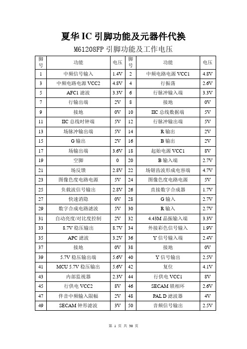
夏华IC引脚功能及元器件代换M61208FP引脚功能及工作电压
J系列CPU(SDA555X)各脚功能及电压
TDA16846功能脚简介
STR-G5653引脚功能及电压
ST6378引脚功能
TDA6210Q引脚功能
AN7583引脚功能
TA8720AN AV开关
SDA9380引脚功能
TDA8362引脚功能
厦华彩电各型号中周内置电容值
厦华彩电显像管、高压包及电路主要参数对照表(一)
第10 页共30 页
第11 页共30 页
第12 页共30 页
第13 页共30 页
第14 页共30 页
第15 页共30 页
第16 页共30 页
第17 页共30 页
第18 页共30 页
第19 页共30 页
厦华彩电行包代换表
第20 页共30 页
第21 页共30 页
第22 页共30 页
第23 页共30 页
第24 页共30 页
第25 页共30 页
开关变压器代用表
1/2W稳压管型号稳压值
场效应管K3116可用K2645代用。
D400可用C2344代用。
C2344可用C5248代用厦华彩电机型与CPU型号对应表。
LD7575PS应用以及厂家显示器电源IC代换
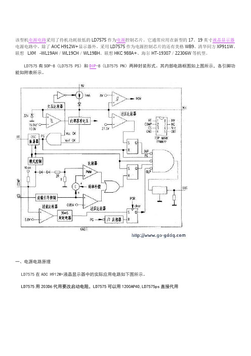
该型机电源电路采用了待机功耗很低的LD7575作为电源控制芯片。
它通常应用在新型的17、19英寸液晶显示器电源电路中。
除了AOC H912W+显示器外。
采用LD7575作为电源控制芯片的还有美格WB9、清华同方XP911W、联想LXM -WL19AH/WL19CH/WL19BH、联想HKC 988A+、海尔HT-19307/22306W等机型。
LD7575有SOP-8(LD7575 PS)和DIP-8(LD7575 PN)两种封装形式。
其内部电路框图如上图所示,各引脚功能如附表所示。
一、电源电路原理LD7575在AOC H912W+液晶显示器中的实际应用电路如下图所示。
LD7575用203D6代用要改启动电阻,LD7575可以用1200AP40,LD7575ps直接代用1.整流滤波电路220V交流电压经过共态扼流圈L901、L902、跨接线路电容C909进行EMI滤波。
其中C909用于滤除低频正态噪声。
R900、R902用于拔掉电源时对电容C909起放电作用。
220V交流经BD901桥式整流输出波动直流电经滤波电容C907滤波后,生成310V的直流电压。
负温度系数热敏电阻NRgOI用来限制启动时的电流。
防止启动电流过大烧毁保险丝。
2.启动/振荡电路刚启动开关电源时,IC901(LD7575PS)所需的启动工作电压由,±310V直流电压经过R905限流后加至IC901(8)脚实现开机启动操作。
LD7575PS开始工作后。
其(5)脚输出PWM脉冲波(该脉冲控制功率管Q900并按其工作频率进行开关动作)。
Q900工作在开关状态后,开关变压器T901在次级绕组输出整机需要的各种供电电压。
‘开关变压器T901的(1)-(3)绕组产生的高频电压经R610限流、D901整流、C911滤波后。
直接输入至LD7575PS的(6)脚作为正常工作状态的供电电压。
在正常工作时。
其LD7575PS的(6)脚必须有,14V左右的电压为芯片供电。
IC 代码及代换型号查询(参考资料)

CODES:DJ= - RT8202AGQWDJ- - RT8202APQWDK- - RT8204PQW WQFN 3x3-16JL= - RT8204AGQW WQFN 3x3-16FR= - RT8204BGQW WQFN 3x3-16H6= - RT8204CGQW WQFN 3x3-16CJ= - RT8205AGQWCK= - RT8205BGQWCL= - RT8205CGQWCB= - RT8205DGQWDT= - RT8205EGQWEM= - RT8205LGQW [RT8205AGQW]EN= - RT8205MGQW [RT8205CGQW]CP= - RT8207GQWDH= - RT8207AGQWEF= - RT8207LGQWJ7= - RT8207MGQWDS= - RT8223BGQW LDO Output: 70mA11= - RT8223NGQW LDO Output: 100mA [RT8223BGQW] 20 - RT8223PZQW LDO Output: 100mA [RT8223BGQW] EP= - RT8223LGQW LDO Output: 100mA [RT8223AGQW] EQ= - RT8223MGQW LDO Output: 100mA [RT8223BGQW]FF= - RT8208AGQWFG= - RT8208BGQWH8= - RT8208DGQW30= - RT8208EGQW31= - RT8208FGQWFH= - RT8209AGQW WQFN-16L 3x3A0= - RT8209BGQW WQFN-14L 3.5x3.5A3= - RT8209EGQW WQFN-14L 3.5x3.5JX= - RT8209LGQW WQFN-16L 3x3A8= - RT8209MGQW WQFN-14L 3.5x3.5K0= - RT8209NGQWA6= - RT8209PGQWEL= - RT8015ADZ= - RT8113CZ= - RT8561AGQWD9= - RT9716AGQWC7= - RT9293-20replacements:ISL6236 = RT8206A = PM6686ISL6237 = RT8206BISL6268 = APW7138TPS51117 = RT8209BTPS51116 = RT8207ISL6227 = APW7108TPS51125 = RT8205B = UP6182TPS51123 = RT8223MISL6251 = G5209P2805MF = G5933G86-631-A2 = G86-621 = G86-620 = G86-630 = G86-603 = G86-920 G86-920-A2 = G86-921-A2GF-GO7200-N-A3 = GF-GO7300T-N-A3GF-GO7300-N-A3 = GF-GO7300T-N-A3GF-GO7400-N-A3 = GF-GO7400T-N-A3QD-NVS-110M-N-A3 = QD-NVS-110MT-N-A3G86-740-A2 = G86-741-A2GM45 = GL40HM55 = HM57HM65 = HM67216-8018 = 216-8020216-4026 > 216-4024 > 216-4022216PABGA13F = 216PACGA14F216PBCGA15FG = 216PBCGA15F216QMAKA14FG = 216RMAKA14FG216RMAKA14FG = 216QMAKA14FG216MJBKA15FG = 216MJBKA11FG216PNAKA13FG = 216PMAKA12FG216PQAKA12FG = 216PQAKA13FG216PQAKA13FG = 216PQAKA12FG216PMAKA13FG = 216PMAKA12FG216PLAKB26FG = 216PLAKB24FG216CPIAKA13FL = 216CPIAKA13F216BS2BFA22H = 216BS2BFB23H216DCP4ALA12FG = 216ECO4ALA13FG 216MSA4ALA12FG = 216MCA4ALA12FG 216MPA4AKA21HK = 216MPA4AKA22HK 216-0674024 = 216-0674026216-0707007 = 216-0707001216-0707001 = 216-0707011216-0707005 = 216-0707009216-0707009 = 216-0707005216-0707011 = 216-0707001218S4PASA14G = 218S4PASA13G218S4EASA31HK = 218S4EASA32HK 215NSA4ALA12FG = 216MSA4ALA12FG 216-0772003 = 216-0772000IT8500E = IT8502E = IT8512EWPCE775 = WPC773WPC8763 = WPC8769SMSC KBC1098 = SMSC MEC1308RT8205A = TPS51125ISL6236 = RT8206A = PM6686ISL6268 = APW7138TPS51117 = RT8209BTPS51116 = RT8207ISL6227 = APW7108 TPS51125 = RT8205B = UP6182TPS51123 = RT8223MP2805MF = G5933SN608090 = ISL6237 = 51427 RT8206BISL6237 = MAX17020 = MAX8778 = TPS51427 = RT8206B PM6686 = TPS17020UP1585QQAG (EM = EC) = TPS51123A = RT8223P ( EQ=XX) MAX8734A = RT8203MAX 8724 = MAX1908ISL88731= BQ24745ISL 6266 = ISL 6262ISL 62883 = ISL 62882ALC883 = ALC660RT8223 = 51123(DH=CH)= (DH=CA)= RT8207W8769 = W8763SN608090 =ISL6237 = 51427 = RT8206BIT8500E = IT8502 = IT8512ISL6266 = ISL6262ISL62883 = ISL628823RT8223 = RT8205ITE8502E = ITE8512EITE8512EKXS= ITE8512EKXOISL6237 = MAX17020 = MAX8778 = TPS51427 = RT8206B PM6686 = TPS17020UP1585QQAG (EM EC) = TPS51123A = RT8223P(EQ=)ISL88731=BQ24745RT8206B = ISL 62373MAX8734A = RT82032J493 (G966-93) = RT9018B (DELL VASTRO 1015)KB926QF D3 = KB926QF COKB3926QF D3= KB3926QFRT8205(A) = TPS51125(EF = DE 41J) = RT8207LGQW(CJ=CL 40W) = TPS51125KB3310QF-A0 = KB3310QF-B0 Asus All-in-One PC ET1602CKB3310QF-C1 = KB3310QF-B0 Asus EeePC 900KB3926QF-A1 = KB3926QF-A2 Quanta AT3KB3926QF-C0 = KB926QF-D3 HP DV5KB3926QF-C0 = KB3926QF-D2 Quanta OP6, QT6KB3930QF-A2 = KB930QF-A1 Quanta R23KB926QF-B1 = KB926QF-C0 Compal LA-3551PKB926QF-B1 = KB926QF-D3 Compal LA-6552PKB926QF-D3 = KB926QF-C0 Lenovo G550 - Compal LA-5082PKB926QF-E0 = KB926QF-C0 Compal LA-6061PKB926QF-E0 = KB926QF-D3 Compal LA-6311P, Lenovo G555 (LA-5972P)KB926QF= KB926QF-D2 Compal LA-6421P, LA-6221PWPCE773 = WPCE775WPC8763LDG = WPC8769LDG WistronBiwa, Aspire 5920G - Quanta ZD1WPC8769LA0DG = WPC8769LDG Alienware M15x - Quanta MX3NPCE781LA0DX = NPCE781BA0DXNPCE781LA0DX = NPCE783LA0DX Quanta ZQ1NPCE795GA0DX = NPCE795LA0DX Quanta ZYGIT8500E = IT8502E Asus K50IJIT8502E = IT8500E Asus K40AB, K40C, K50C, K50ABIT8502E = IT8512E Asus K50IJIT8512E = IT8500E Acer 6920IT8511TE-BXS = IT8510TE-GXA Asus X51R/RLMEC1300-NU = MEC1308-NU Samsung R530 (BREMEN-L3, 1.0,BREMEN-L4, r1.4), Samsung R519 (BONN-L)TPS 51125A = RT8205BGQW =(CK=CD C47)RT8209A = FH=CG CU1RT8204C = H6=CH JOXRT8205 = TPS51125SN10504 =SN0608098 RHBRMAX 8724 = MAX1908(EF= DE) = UP6163AG (1.5V)isl 6266 = isl 6262isl 62883 = isl 628823rt 8223 = rt 8205i/o ite 8502e = ite 8502eite8512eite8512e kxs= ite8512e kxoISL6237 = MAX17020 = MAX8778 = TPS51427 = RT8206BPM6686 = TPS17020UP1585QQAG (marked EM EC) = TPS51123A = RT8223P(marked EQ=) Charger ISL88731=BQ247451: RT8206B = ISL 623732: MAX8734A = RT820323: J493 (G966-93) = RT9018B (DELL VASTRO 1015)4: I/O... KB926QF D3 = KB926QF COKB3926QF D3= KB3926QFRT8205(A) = TPS51125%Ef=de 41j ------------------- rt8207lgqwcj=cl 40w ------------------- tps51125Microcontrollers (KBC, SUPER I/O, EC, etc) interchangeabilityTable interchangeability multicontrollers1EC1 Replacement EC2 PlatformKB3310QF-A0 > KB3310QF-B0 Asus All-in-One PC ET1602CKB3310QF-C1 > KB3310QF-B0 Asus EeePC 900 (KB3926QF-A1 > KB3926QF-A2 Quanta AT3KB3926QF-C0 > KB926QF-D3 HP DV5KB3926QF-C0 <-> KB3926QF-D2 Quanta OP6, QT6KB3930QF-A2 > KB930QF-A1 Quanta R23KB926QF-B1 > KB926QF-C0 Compal LA-3551PKB926QF-B1 > KB926QF-D3 Compal LA-6552PKB926QF-D3 > KB926QF-C0 Lenovo G550 - Compal LA-5082PKB926QF-E0 > KB926QF-C0 Compal LA-6061PKB926QF-E0 > KB926QF-D3 Compal LA-6311P, Lenovo G555 (LA-5972P)KB926QF-E0 > KB926QF-D2 Compal LA-6421P, LA-6221PWinbond1WPCE773 <-> WPCE775WPC8763LDG <-> WPC8769LDG WistronBiwa, Aspire 5920G - Quanta ZD1WPC8769LA0DG > WPC8769LDG Alienware M15x - Quanta MX3 (Maddog 2.5)nuvoTon,NPCE781LA0DX > NPCE781BA0DXNPCE781LA0DX > NPCE783LA0DX Quanta ZQ1NPCE795GA0DX > NPCE795LA0DX Quanta ZYGITEIT8500E > IT8502E Asus K50IJIT8502E > IT8500E Asus K40AB, K40C, K50C, K50ABIT8502E <-> IT8512E Asus K50IJIT8512E > IT8500E Acer 6920IT8511TE-BXS > IT8510TE-GXA Asus X51R/RLSMSC2MEC1300-NU <-> MEC1308-NU Samsung R530 (BREMEN-L3, 1.0, BREMEN-L4, r1.4), Samsung R519 (BONN-L)ISL62882<->ISL62883。
8205S 6脚IC规格书

tD(ON) tr
tD(OFF) tf
VDD = 10V , ID = 1A VGEN = 4.5V RL = 10 ohm RGEN = 6 ohm
10
ns
8.2
ns
25
ns
6.7
ns
Total Gate Charge
Gate-Source Charge
Gate-Drain Charge
Note: b. Pulse Test:Pulse width ≤ 300us , Duty Cycle ≤ 2% . c. Guaranteed by design , not subject to production testing .
±100 nA
Gate Threshold Voltage
VGS(th) VDS = VGS , ID = 250uA 0.6 0.9 1.5 V
Drain-Source On-State Resistance
RDS(on)
VGS = 4V , ID = 4.3A VGS = 2.5V , ID = 3.4A
10
100
600
Square Wave Pulse Duration (sec) Figure 10. Normalized Thermal Transient Impedance Curve
4
ID , Drain Current (A)
20 16 12 8 4 0
0 0.5 1 1.5 2.0 2.5 3.0
VGS , Gate-to-Source Voltage (V) Figure 2. Transfer Characteristics
2
1.75
VGS= 4V ID= 4.3A
6脚电源芯片

6脚电源芯片电源芯片是现代电子设备中不可或缺的关键部件,其作用是将输入的电能转换为适合设备工作所需的不同电压或电流。
而6脚电源芯片即是一种常见的电源芯片类型,下面将对其进行详细的介绍。
首先,6脚电源芯片是一种非常常见的封装形式,其正面有6个金属触点,便于与电路板进行连接。
这种电源芯片通常被广泛应用于手机、平板电脑、电视、电脑以及其他许多消费电子产品中,以提供稳定的电源供应。
接下来,6脚电源芯片具有多种功能和特点。
首先,它可以实现输入电源的稳压和过压保护功能,确保输出电压在规定范围内恒定稳定。
其次,它还能够提供电池充电管理功能,对电池进行合理的充电控制,防止过充和过放。
此外,6脚电源芯片还具备短路保护、过流保护以及过温保护等功能,以确保设备和用户的安全。
6脚电源芯片的工作原理一般分为两个阶段:开关调节和线性稳压。
在开关调节阶段,该芯片内部有一个开关电源电路,它通过开关管的导通或断开来控制输入电能的流动,以实现高效的电能转换。
这一阶段可以实现较高的效率和较小的尺寸。
而在线性稳压阶段,芯片通过线性稳压器将开关输出的电压再次调整为稳定的输出电压。
这一阶段可以提供更为稳定和干净的电源输出。
此外,6脚电源芯片在设计和使用上还需要注意以下几个方面。
首先,选择合适的芯片型号和规格,以满足设备的要求。
其次,正确连接芯片的引脚,确保电路的稳定工作和正常输出。
第三,根据实际需求进行布局和散热设计,以保证芯片的温度不能过高,否则会影响其性能和寿命。
综上所述,6脚电源芯片是一种常见的封装形式,广泛应用于各种电子设备中。
其具有稳定电源输出、充电管理以及多重保护功能等特点,可提供稳定可靠的电源供应。
在使用过程中,需要选择合适的芯片并正确连接引脚,同时注意散热和布局设计,以确保芯片的正常工作和可靠性。
18种常用贴片三极管型号识别与液晶电源常用贴片6脚芯片资料

1Z 2N6517;20F TSDF1220;20V PZM20NB;20Y BZV49-C20;22V PZM22NB ;22Y BZV49-C22;
24V PZM24NB;24Y BZV49-C24;27V PZM27NB;2A 2N3906 ;2A 2N3906;
1P 2N2222A;1P 2N2222A ;1P BC847PN;1V 2N64267;1V- BF820W;1VpBF820 ;1Vt BF820;
贴片三极管型号代码
1Vt BF820W ;1W 2N3903 ;1W-;BF822W ;1Wt ;BF822W ;1Wp;BF821 ;1Wt BF821;
18种常用贴片三极管型号识别与液晶电源常用贴片6脚芯片资料
18种常用贴片三极管型号识别与液晶电源常用贴片6脚芯片资料
18种常用贴片三极管型号识别与液晶电源常用贴片6脚芯片资料
型号表面标识
AO3400(标识AO9T)
TL431A(标识431)
78L05(标识78L05)
S8050(标识J3Y)
S8550(标识2TY)
2A4 SOT346;2A7 SOT346;2B BC849B ;2B 2N2907 ;2B- BC849BW;2Bp BC849B
2BR BC849BR;2Bs BC849B ;2Bs BC849BW ;2Bt BC849BWБайду номын сангаас2BZ 2N2907;2C BC849C
2C- BC849CW;2Cp BC849C;2CR BC849CR ;2Cs BC849C;2Cs BC849CW;2Ct BC849C;
- 1、下载文档前请自行甄别文档内容的完整性,平台不提供额外的编辑、内容补充、找答案等附加服务。
- 2、"仅部分预览"的文档,不可在线预览部分如存在完整性等问题,可反馈申请退款(可完整预览的文档不适用该条件!)。
- 3、如文档侵犯您的权益,请联系客服反馈,我们会尽快为您处理(人工客服工作时间:9:00-18:30)。
荆州市胡振华资料 ----- 6PIN电源芯片的功能引脚及代换注意事项典型应用电路
2013年1月6日
14
5
6
12
3
456YW P 1
8 2
3
4
7
6
5
TOP MARK YYWWPP
O U T
V C C
N C
C S
36 pp
Fig. 15
A 230nS leading-edge blanking (LEB) time is included in the input of CS pin to prevent the false-trigger from the current spike. In the low power application, if the total pulse width of the turn-on spikes is less than 230nS and the negative spike on the CS pin below -0.3V, the R-C filter is free to eliminate. (As shown in Fig.16). However, the total pulse width of the turn-on spike is
determined according to output power, circuit design and PCB layout. It is strongly recommended to adopt a smaller R-C filter (as shown in Fig. 17) for larger power application to avoid the CS pin being damaged by the negative turn-on spike.
Output Stage and Maximum Duty-Cycle
An output stage of a CMOS buffer, with typical 300mA driving capability, is incorporated to drive a power MOSFET directly. And the maximum duty-cycle of LD7536 is limited to 75% to avoid the transformer
Voltage Feedback Loop
The voltage feedback signal is provided from the TL431 at the secondary side through the photo-coupler to the COMP pin of the LD7536. Similar to UC3842, the LD7536 would carry a diode voltage offset at the stage to Fig. 16 Fig. 17。
