DF310E微量氧分析仪(中文)
微量氧分析仪应用

微量氧分析仪微量氧分析仪主要用于工业在线、实验室以及瓶装高纯N₂(氮气)、Ar(氩)、He(氦)、Ne(氖)和混合气体中的微量氧、痕量氧的快速检测,尤其适用于空分装置和各气体分装厂高纯气体中微量、痕量氧的检测;同时也适用于石油化工、冶金等行业的高纯工艺性气体、保护性气体中微量氧的快速检测。
特别是对于含氧量< 1 PPMv的钢瓶气样,检测准确、快速、简便,具有最大优势。
微量氧分析仪分为两种分析原理:分别为燃料电池法微量氧分析仪和氧化锆微量氧分析仪。
RL-100L系列氧气分析仪采用电化学或者氧化锆对生产过程中氧气进行精度的测量分析。
微处理器对传感器的信号进行放大处理并清晰显示以及进行 4-20mA或其他方式传送到其他控制系统中。
保证了生产过程对氧气的控制。
对于特殊应用环境,我们用户可以根据需要定制合适的方案。
微量氧分析仪校准:使用氮气进行校零,用标准气体进行量程校准。
RL-S100L型微量氧分析仪技术参数:测量原理:进口电化学燃料电池式;测量范围:0.00~10/100/1000PPm;精度:≤±3%FS(0.00~10PPm);≤±2%FS (10~100PPm) ;≤±1%FS (100PPm~1000PPm) ;重复性:≤±1%稳定性:零点漂移≤±1%FS/7d量程漂移:≤±1%FS/7d样气流量:400±50ml/ min;响应时间:T90≤15秒;模拟输出:4~20mA标准信号输出,负载电阻小于500欧(0~10V 可选)数字输出:标准的RS485/RS232通讯口,可与计算机实现双向通讯;触点输出:双继电器输出220VAC,10A或24VDC,2A;样气压力:0.05 MPa≤入口压力≤0.20MPa;工作环境:温度:-15℃~+45℃;湿度:≤90%RH;工作电源:220V~240VAC,50/60Hz;外形尺寸:145mm(宽)× 145mm(高)× 265mm(深);安装尺寸:135mm(宽)×135mm(高);重复性:≤±1%;稳定性:零点漂移≤±1%FS/7d;量程漂移≤±1%FS/7d;样气流量:400±50ml/ min;响应时间:T90≤15秒;样气压力:0.05 MPa≤入口压力≤0.25MPa;工作环境:温度:-15℃~+45℃;湿度:≤90%RH;工作电源:12VDC;外形尺寸:300mm(宽)× 120mm(高)× 270mm(深);充电电源:(220±22)VAC,(50±5)Hz,充电器自带充电保护功能;使用寿命:>6年(规范操作正常使用条件下);气路接口:Φ6软管(可根据客户订制);仪器特点:点阵式320*240彩色LCD屏,显示直观,操作简单方便;选用进口燃料电池式电化学传感器,具有寿命长、精度高、响应快等特点,可根据现场所测背景气选择不同的传感器;定时自动存储功能,可随时查看存储数据;配有大功率电池,一次充电保证仪器连续工作30小时以上;应用领域:空分制氮、化工流程、磁性材料等高温烧结炉保护气体、电子行业保护性气体以及玻璃、槽车、充氮食品包装袋或气罐,建材行业及各种混合气体中微量氧的便携快速检测分析。
微量氧分析仪使用过程中的注意事项 分析仪常见问题解决方法
微量氧分析仪使用过程中的注意事项分析仪常见问题解决方法微量氧分析仪是一种常用的分析仪器,接受完全密封的燃料池氧传感器是当前国际上先进的测氧方法之一,由高活性的氧电极和铅电极构成,浸没在KOH溶液中。
微量氧的微量氧分析仪是一种常用的分析仪器,接受完全密封的燃料池氧传感器是当前国际上先进的测氧方法之一,由高活性的氧电极和铅电极构成,浸没在KOH溶液中。
微量氧的分析方法紧要有比色法、化学电池法、黄磷发光法、浓差电池法和气相色谱法。
微量氧分析仪使用过程中的注意事项:1、分析仪取样管路的密闭性微量氧分析仪的配套管线必需确保密封,很微小的泄漏都会使环境空气中的氧扩散进来,造成测量数值偏高。
虽然在测量中,样气压力大于环境压力,但样气中的氧是微量级的,依据法拉利定律,氧的分压与其体积含量成正比,大气中含有约为21%的氧,与以PPM计算浓度的样气的氧分压相差一万倍左右,因而气样中微量氧的分压远低于大气中的氧分压,当显现泄漏时,大气中的氧便会从泄漏部位快速扩散进来。
其次,取样管线应尽可能短些,接头尽可能少,要保证接头及阀门密封良好,管线连接完毕后,应做气密性检查。
2、取样管材质的选择管线材质基本上以铜质或不锈钢管线为好,次选聚四氟乙烯管。
禁选乳胶管、白胶管之类管材,其气密性和材质抗渗透性太差,测量微量氧在标准测量压力下误差太大。
管线外径通常我们选择6毫米或1/4IN,也有选择3毫米或1/8IN,总之,不锈钢管,清洗、脱脂,保持管内壁光滑干净,对于痕量级(〈1PPMV)氧的分析,应选择内壁抛光的不锈钢管。
所选择的阀门、接头,死体积应尽可能小。
3、取样分析的时候考虑温度的因素为防止样品中的水分在管壁上冷凝凝结,造成对微量氧的溶解吸取,应依据情况对取样管线实行绝热保温或伴热保温措施。
检测液氮中的微量氧时,尤其要注意加温措施,不然,由于氧沸点低于氮沸点13度,样品气不均匀气化,会使测量值严重偏低。
4、取样点离分析仪的距离越近越好微量氧分析仪的测量位应尽可能与测量点接近,以避开过长的管线和过多的不确定因素,影响测量数据的牢靠性。
微量氧分析仪使用指南及注意事项
微量氧分析仪使用指南及注意事项微量氧分析仪属于气体分析仪器,紧要用于测量气体样品中的氧气浓度。
本文档将针对微量氧分析仪的使用方法和注意事项进行认真介绍。
一、准备工作在使用微量氧分析仪之前,请先做好以下准备工作:1.确认气样的构成和浓度,依照需求调整气路连接和阀门设置;2.查看氧分析仪是否处于开启状态,若未开启,请先打开主电源开关;3.检查氧气浓度探测器是否处于正常温度下(一般为常温)。
二、操作流程使用微量氧分析仪的流程一般包括样品引入、预处理、分析和结果输出。
2.1 样品引入将样品接入气路系统,调整阀门开关,并通过外部压缩气源或吸气泵将样品吸入气体分析仪内进行预处理。
注意事项:1.样品应尽量避开混入油雾等污染物,以避开对样品分析结果产生影响;2.对于高浓度氧气样品,应尽可能降低其浓度后再进行分析,以避开氧气的燃烧不安全;3.气路系统中的管路和容器应经过定期检查和维护,确保其正常功能和清洁度。
2.2 预处理样品进入分析仪后需要进行确定的预处理,以确保分析结果的精准度。
注意事项:1.样品在进入分析仪之前需要通过吸附剂或过滤器进行预处理,去除其中的水分、微量污染物等杂质;2.在进行预处理时需注意气路系统的密封性,确保样品不会泄漏或逸出;3.气体分析仪预处理装置的维护和更换应依照设备说明书的操作方法进行。
2.3 分析样品预处理完毕后,进入分析阶段。
注意事项:1.确认样品氧气浓度的范围,调整氧气分析仪参数,确保其适应样品的浓度要求;2.利用前置操作器和微电脑掌控器等装置对样品进行处理,并保证其负载量和精度;3.在分析中应注意氧气浓度探测器的使用方法,调整探测器的灵敏度和测量范围。
2.4 结果输出分析完成后,可通过结果显示器或打印机等装置,对分析结果进行输出。
注意事项:1.检查分析结果的精准性和合理性,对于不一致或有疑问的结果需重新进行分析;2.氧气分析仪容器和管路等配件需进行清洗和维护,以确保其持续性能和牢靠性。
GXH-3010E型使用说明书

GXH -- 3010E型便携式红外线分析器安装使用说明书01080254号北京市华云分析仪器研究所有限公司目录一、概述 (1)二、主要技术数据 (1)三、仪器结构与工作原理 (2)四、仪器的使用与调校 (4)五、仪器的故障及其排除 (6)六、仪器运输与保管 (7)七、仪器的成套性: (7)八、制造厂的保证 (7)感谢各位用户使用本仪器,为了能正确使用仪器,在使用前请仔细阅读使用说明书。
一、概述GXH — 3010E 型便携式红外线分析器,是为环境监测、环境保护、农业与林业科研、人防系统、卫生监督及疾控中心研制的小型测量仪器。
仪器能快速、准确地对室内环境中的二氧化碳浓度进行检测。
因为仪器能用内置锂电池供电,所以还能实现对室外环境及野外作业场所的CO2进行检测。
仪器为线性化输出,直读浓度、液晶显示、保证三位有效数字。
本仪器是原GXH — 3010D 型便携式CO2分析器的改进型,除保留原机型特点外,仪器的整体结构和操作功能作了重大改进。
仪器可使用交流与直流两种供电方式,并设有充电线路及充电保护,使用非常灵活方便。
仪器的光学部件结构先进、合理,可以可靠的长期运行。
仪器的关键器件采用进口或国产军品。
因此,整个仪器具有体积小、耗电省,可靠性高的特点。
本仪器的使用环境温度在 0℃~35℃,相对湿度不大于 85% RH 。
周围环境没有腐蚀性气体及强烈的机械震动和电磁干扰。
二、主要技术数据1.基本参数a) 测量范围:0—0. 500% CO2b) 电源电压:220V±22V AC (使用外接电源时)c) 消耗功率:≤6Wd) 仪器重量:≤2.7kge) 外型尺寸(mm):210×172×85(长×宽×高)2.仪器技术指标:a) 线性误差:±2% F·Sb) 重复性:≤1%F·Sc) 稳定性:零点漂移:≤±2% F·S/h量程漂移:≤±2% F·S/3hd) 响应时间:T0~T90≤10se) 预热时间:≤5min (在实验室使用时要预热30分钟)3. 仪器额定工作条件(室内)a) 环境温度:0℃~35℃b) 相对湿度:<85% RHc) 大气压力:70~106kPad)电源电压:220V±22V AC (外接电源供电时)电源频率:50Hz±1Hz;e) 工作位置:水平位置;4. 测量气体进入仪器的被分析气体应符合下列条件:a)含水量:相对湿度<85%;b)含尘量:<0.1g/m2;c)腐蚀性气体:(SO2、H2S、NH3……)<0.005%;d)温度:0℃~35℃;e)流量:0.5 L/min~2.0L/min;三、仪器结构与工作原理1、仪器结构仪器的系统方框图如图二所示:图二仪器系统的方框图1 显示器2 检查/测量转换开关3 进气口4 切换阀 5电源开关6泵开关 7 终点电位器 8 零点电位器图三仪器示意图当仪器工作时,直流电机带动调制盘上的两种滤光片旋转,将红外线光源发出的能量调制成两种不同时间顺序的能量,一种是3.9μm的参比能量,一种是4.26μm的分析能量。
微量氧分析仪分类特点及原理介绍
微量氧分析仪分类特点及原理介绍微量氧分析仪主要用于测定氧气含量,是一种非常重要的分析仪器。
经过多年的发展,微量氧分析仪已经形成了多种分类,每种分类都具有一些自身的特点。
本文将对微量氧分析仪的分类和原理进行介绍。
一、微量氧分析仪分类1.电化学型电化学型微量氧分析仪采用电化学传感器测定氧气,将电化学传感器放置在样品环境中,当氧气分子到达传感器表面时,这些分子会与电化学传感器的电极反应,产生电流。
通过检测电流强度可以确定氧气的含量。
电化学型微量氧分析仪使用方便、响应速度快、准确度高,是最常用的微量氧分析仪之一。
但是该型号微量氧分析仪价格较高,需要定期校准,无法分析高温和富氧气体等样品。
2.荧光型荧光型微量氧分析仪利用氧气对感光物质的荧光强度的影响来测定氧气的含量。
荧光型微量氧分析仪可以分析各种气体,是最常用的非电化学传感器微量氧分析仪之一。
该型号微量氧分析仪价格适中,操作简单,可靠性高,但是使用寿命较短,无法分析灰色气体和高浓度氧气。
3.红外型红外型微量氧分析仪利用氧气对特定波长红外线的吸收能力,通过测量吸收光的强度来分析氧气的含量。
该型号微量氧分析仪可分析多种气体,但是灵敏度较低,需要较高的样品流速以确保准确性。
4.恒温型恒温型微量氧分析仪利用恒定温度下氧气的扩散速率与氧气含量成线性关系的原理,通过测量氧气分子在样品管中扩散的时间来分析氧气的含量。
该型号微量氧分析仪具有灵敏度高、稳定性好和准确度高等特点,但是对样品温度要求苛刻,需要定期校准以确保准确性。
二、微量氧分析仪原理微量氧分析仪的原理是根据氧气分子与特定物质的相互作用产生的信号来确定氧气含量。
这些信号可以是电化学反应、荧光强度、红外吸收或氧气扩散时间等。
一般情况下,微量氧分析仪会设置一个样品室和一个控制仪器。
样品室用来将样品气体与探头接触,探头通常是一根指向样品室的电极,用来感应与样品气体反应后产生的电流或荧光。
控制仪器则用来记录和分析这些信号,并计算出氧气的含量。
TG-310分析仪(90[1].00-9.99)
![TG-310分析仪(90[1].00-9.99)](https://img.taocdn.com/s3/m/2bdf33d15ebfc77da26925c52cc58bd631869319.png)
一、概述TG-310型氧气纯度分析仪是一种盘装式或台式的氧含量检测仪器,特别适用于航空用氧气、医用氧气、空分制氧、以及高压氧仓的氧含量检测分析。
TG-310型氧气纯度分析仪由极限电流传感器和新型微处理器组成。
体积小,重量轻,结构合理,便于安装;其采用的传感器反应灵敏、精确度高。
仪器采用单片机处理与测控,128*64点阵液晶显示被测样气中氧气的含量。
当被测样气中氧含量低于设定的报警点时,仪器会自动报警。
如有特殊需要时,可进行报警输出和标准的RS-232微机接口。
二、主要技术参数1.测量范围:90.00~99.99%O2;3.分辨率:0.01%;4.重复性:≤2% F.S;5.稳定性:零点漂移≤±1%F.S/7d;量程漂移≤±1%F.S/7d;6.预热时间:≤400s;7. 响应时间:τ90≤30s;8.样气流量:300±10毫升/分钟;9.取样压力:≤0.25Mpa;10.输出电流:4~20mA;11.触点容量:220VAC/1A,24VDC/2A;12.工作电源:~220V±10%,50Hz±10%;13.工作环境:温度:-5℃~+45℃;湿度:≤95%RH;14.外形尺寸:260(宽)×140(高)×300(深);15.重量:约3.5kg。
三、工作原理和仪器的面板结构㈠仪器的工作原理TG-310型氧气纯度分析仪由气路系统、电化学传感器、前置放大电路、模数转换电路、单片机、报警输出电路、纯度显示电路和电流输出电路组成。
极限电流传感器将被测样气中的氧含量转换为电信号,经前置放大电路放大整形后,由模数转换电路转换成数字信号,再送到单片机进行处理,然后由纯度显示电路把被测样气中氧气的含量以%O2的形式显示出来;当被测样气中氧气的含量低于报警设定值时,蜂鸣器会自动报警;当被测样气中氧气的含量低于下限控制设定值时,报警输出电路的下限常开触点会接通;当被测样气中氧气的含量高于上限控制设定值时,报警输出电路的上限常开触点会接通。
DeltaF微量氧分析仪()精讲

一、微量氧分析仪在工艺中的作用
1、聚乙烯的精致单元:监测精致单元入口和出口气体是否合 格 PP: rang:0-2ppmv,normal:0.4ppmv,alarm:1ppmv;
2、反应器单元:监测循环气中氧含量和反应器的活度;
3、挤压造粒单元:作用是为对后工段生产的进行安全监测, 在氧气和碳氢含量超标的时候,工艺会采取相应措施去除,防 止产生安全隐患。PP: rang:0-1%, normal: 50ppmv, alarm: 2000ppmv。
3.3
传感器与MIS 1控制器的连接
在MIS 1二次表上最多可装6个通道,可以带12台分析仪,但是 只能带6台氧和6台水表,每一个通道最多只能带一台水表和一台 氧表。
水探头与二次表 连接点
氧池与二次表 连接点
向DCS,PLC,SIS 等系统输送信号
四
预处理
?
箱体内部按要求采用电/蒸汽/热水加热器,保证箱体内冬季温度不低于20℃
8.3、测量值与实际值偏差太大
原因1:管线泄漏 处理方法:检查样品管线气密性
原因2:因子偏差大 处理方法:重新校验 原因3:系统误差偏差大 处理方法:在test菜单里面调节系统误差
谢谢大家!
3.2 微量氧分析仪的使用场合
耗尽型燃料电池式微量氧分析仪针对于一般场合使 用,或在某些特定场合,分析仪比较容易受到损伤的情 况下。而非耗尽型电解法微量氧分析仪一般可用于聚合 反应等比较重要场合; 此外,在一些酸性气体的情况下,当耗尽型燃料电 池式微量氧分析仪无法使用时,也可考虑用非耗尽型电 解法微量氧传感器。
Ambient Temperature 0° to 49°C
•
Sample Requirements
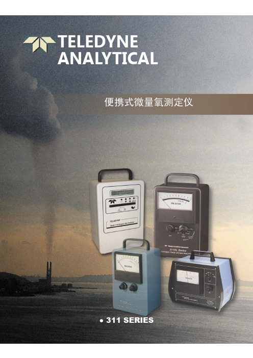
Teledyne 311系列微量氧分析仪
20ppb
0.5%F.S
±2%F.S(±5%在 0-2ppm 量程),在 25℃常温恒压下 ±2%F.S (1ppm 在 0-10ppm)在常温常压下
±5%F.S(±10%在 0-2ppm 量程),在温度在 0-35℃以 ±5%F.S(1ppm 在 0-10ppm)
外恒温恒压下
在操作温度范围以外恒温恒压下
0-35℃(32-95℉)
0-50℃(32-122℉)
90%F.S 在 5-10s 90%<60s(0-10ppm) 90%<90s(0-2ppm)流量为 2.5SCFH
90%在 5-10s 90%<60s(0-10ppmXL
B-2C(微量)、B-1(常量),其他可用
交流电源用于充电,可反复充电的 NICAD 充电电池,110VAC/0.25A,60Hz(100/220VAC,50-60Hz 可选)
311 311TC 311PC 3110
分析
微量 微量 微量 微量 百分 微量
表头
模拟 模拟 模拟 模拟 模拟 数字
认证
FM BASEEFA
FM CENELEC/BASEEFA CENELEC/BASEEFA FM,CENELEC/BASEEFA
应用范围
应用领域 空气分离和液化 纯气态碳氢化合物流路监测 气态单体过程分析-氯乙烯、丙烯、丁二烯、乙烯、橡胶 半导体制造业 手套箱或管路泄漏检测 初级液体给料和可燃液体保护气层的操作 气体纯度鉴定 天然气处理和传输 异型金属的惰性气体焊接 催化剂保护 波峰和回流焊接 核燃料处理和同位素分离 热处理和退火 化学反应分析 顶端空间气体分析 晶体培育 断路器中的 SF6 鉴别 塑料制造
微量氧分析仪的应用如何
微量氧分析仪的应用如何微量氧分析仪是一种用于快速准确分析固体、液体、气体中微量氧含量的仪器。
由于氧在很多化学反应和生物过程中起着重要作用,因此微量氧分析仪在环境保护、食品生产、医药研究等领域都有广泛的应用。
环境保护在环境保护领域,微量氧分析仪主要应用于废水和废气处理的监控和调节。
某些废水和气体的处理过程需要通过氧化反应来去除有害物质,因此在这些处理过程中,需要确定反应器中的氧气浓度以控制反应速率和效率。
通过使用微量氧分析仪,可以实时监测反应器中氧气的浓度,并及时调整反应器中的氧气供应,从而实现高效的废水和气体处理。
食品生产在食品生产领域,微量氧分析仪主要应用于罐装食品和饮料的保鲜和质量控制中。
对于需要长期保存的罐装食品,如果其中氧气浓度过高,则会导致细菌和微生物的生长和繁殖,进而导致食品变质;而氧气浓度过低,则会导致食品味道变差。
因此,在罐装食品生产中,需要通过微量氧分析仪来监测罐中氧气的浓度,并控制罐内氧气的供应,从而实现食品的保鲜和质量控制。
医药研究在医药研究领域,微量氧分析仪主要用于药物生产过程的监测和质量控制。
在药物生产过程中,需要对溶液中的氧气浓度进行精确的控制。
通过使用微量氧分析仪,药品生产厂可以在制药过程中实时监测溶液中氧气的浓度,并根据实际需要进行调整,从而确保药品的质量。
总结综上所述,微量氧分析仪在环境保护、食品生产、医药研究等领域都有广泛的应用。
通过使用微量氧分析仪,企业可以实时监测氧气浓度,并及时调整氧气的供应,从而提高反应速率和效率,保证产品的质量。
同时,微量氧分析仪的操作简便、快速可靠,成本也相对较低,因此其在实际应用中一直受到广泛的欢迎。
微量氧分析仪安全操作及保养规程
微量氧分析仪安全操作及保养规程微量氧分析仪是一种常见的用于测量氧气浓度的仪器,广泛应用于医疗、制药、化工、燃料电池等领域。
为确保使用过程中的安全性和准确性,使用微量氧分析仪时需要遵守一些基本的操作规程和保养要求。
一、安全操作规程1. 仪器安装微量氧分析仪的安装要放在通风良好的地方,不要靠近火源。
2. 电源接通在接通电源前,应确认所使用的电源与仪器电源参数相符,并接好地线。
开机前,应确认所有探头的接头都已插好。
3. 运行时的注意事项在使用时应确保探头处于平稳、垂直的位置,以免影响仪器的测量精度;在操作过程中应注意不要将水或其他液体溅到探头上,以免导致仪器损坏;同时,确保测量系统的各个部分连接紧固、无漏气等情况。
4. 使用后的注意事项使用后应及时清洁各部件。
对于长时间使用后的仪器需重新校准和定期维护以确保仪器的准确性和长期稳定性。
5. 安全事项在使用中,遵守有关安全规程和注意事项。
例如,不要在高温或低温处使用仪器,不要在潮湿或易燃的环境中使用仪器。
使用时,应保持仪器干燥和整洁,不要强行拆卸或更换零件。
二、保养规程1. 仪器清洁使用后应及时清洁各部件,以防止外部杂质侵入仪器对它的影响。
把仪器清洁干净后,再用防水布或其他合适的材料覆盖好,放置在干燥的地方。
2. 仪器维护对于长时间使用后的仪器,应该定期进行校准。
同时,还需要定期检查零件是否磨损,有无松动等现象,及时更换。
对于日常维护,应注意对各部件进行保养,如电源线、探头等等。
3. 仪器保管在仪器放置的地方,应该保持周围的环境温度、湿度、干燥度等指标在安全范围内。
同时,保管时应避免日晒雨淋,应尽量放在通风好、阳光充足的地方。
4. 仪器校准在使用仪器的过程中,如果发现仪器测得结果偏差较大等问题,就需进行校准,确保仪器的测量结果更加准确。
结束语微量氧分析仪在日常应用中,遵照合理的安全操作规程和保养要求,可以更好地确保仪器的测量精度、长期稳定性及使用寿命。
使用前一定要将仪器的使用说明仔细阅读,遵照操作和保养要求,让仪器更好地为生产和生活服务,确保安全运行。
3000TA微量氧分析仪中文说明书(总结)

3000TA微量氧分析仪介绍1.1、概述Teledyne Analytical Instruments的3000TA微量氧分析仪是基于微处理器的测量气体中ppm级O的分析仪。
本手册只包含通用的3000TA的盘装或架装仪表的内容,这些仪表应用于非危险的室内2环境中。
1.2、典型应用·惰性气体的保护监测;·空气分离和液化;·化学反应监测;·半导体生产;·石化过程控制;·质量保证;·气体分析检验。
1.3、分析仪的主要特点3000TA微量氧分析仪先进而便于使用,主要特点:·两行字符显示,微电子驱动,连续的提示和通知操作者;·大型高亮度显示器,高分辨率、精确的O2读数,从ppm级到25%氧含量;·不锈钢传感器模块;·先进的微燃料电池,专门设计用于微量分析,保用期1年,使用寿命达2年;·通用的宽量程分析应用;·8位微处理器(CMOS),32KB RAM和128KB ROM;·3个用户可定义的输出范围(0-10ppm到0-25%),能最好地与用户的过程设备匹配;·用传统的20.9%作空气标定;·对于给定的测量,自动量程使分析仪自动地选择预置的量程,手动切换允许固定在一个希望的范围内分析;·两个可调的含量报警和系统故障报警;·在启动初期和根据命令进行自诊断,连续的电源监测;·两种RFI防护方法;·4个模拟量输出:两个用于测量(0-1vdc和隔离的4-20mAdc)和两个量程定义输出;·传统的通用的钢制盘装或架装机壳,带有滑出型电气抽屉。
1.4、型号设计3000TC:标准型。
3000TC-C:除标准配置外,还有分立的用于零点和量程气接口和内置的控制阀,控制阀由3000TC控制,与分析仪的操作同步地在气体间切换。
3110 微量氧分析仪操作手册(英文)

Teledyne Analytical InstrumentsOPERATING INSTRUCTIONS FORModel 3110Portable Trace Oxygen AnalyzerDANGER Toxic gases and or flammable liquids may be present in this monitoring system. Personal protective equipment may be required when servicing this instrument. Hazardous voltages exist on certain components internally which may persist for a time even after the power is turned off and disconnected.Only authorized personnel should conduct maintenance and/or servicing. Before conducting any maintenance or servicing, consult with authorized supervisor/manager.Copyright © 2005 Teledyne Analytical InstrumentsP/N M77970 10/16/2005 ECO:Model 3110ii Teledyne Analytical InstrumentsAll Rights Reserved. No part of this manual may be reproduced, transmitted, transcribed, stored in a retrieval system, or translated into any other language or computer language in whole or in part, in any form or by any means, whether it be electronic, mechanical, magnetic, optical, manual, or otherwise, without the prior written consent of Teledyne Instruments / Analytical Instruments, 16830 Chestnut Street, City of Industry, CA 91748. WarrantyThis equipment is sold subject to the mutual agreement that it is warranted by us free from defects of material and of construction, and that our liability shall be limited to replacing or repairing at our factory (without charge, except for transportation), or at customer plant at our option, any material or construction in which defects become apparent within one year from the date of shipment, except in cases where quotations or acknowledgements provide for a shorter period. Components manufactured by others bear the warranty of their manufacturer. This warranty does not cover defects caused by wear, accident, misuse, neglect or repairs other than those performed by TAI or an authorized service center. We assume no liability for direct or indirect damages of any kind and the purchaser by the acceptance of the equipment will assume all liability for any damage that may result from its use or misuse.We reserve the right to employ any suitable material in the manufacture of our apparatus, and to make any alterations in the dimensions, shape or weight of any parts, in so far as such alterations do not adversely affect our warranty.Important NoticeThis instrument provides measurement readings to its user, and serves as a tool by which valuable data can be gathered. The information provided by the instrument may assist the user in eliminating potential hazards caused by his process; however, it is essential that all personnel involved in the use of the instrument or its interface, with the process beingmeasured, be properly trained in the process itself, as well as all instrumentation related to it. The safety of personnel is ultimately the responsibility of those who control process conditions. While this instrument may be able to provide early warning of imminent danger, it has no control over process conditions, and it can be misused. In particular, any alarm or control systems installed must be tested and understood, both as to how they operate and as to how they can be defeated. Any safeguards required such as locks, labels, or redundancy, must be provided by the user or specifically requested of TAI at the time the order is placed.Therefore, the purchaser must be aware of the hazardous process conditions. The purchaser is responsible for the training of personnel, for providing hazard warning methods and instrumentation per the appropriate standards, and for ensuring that hazard warning devices and instrumentation are maintained and operated properly.Teledyne Analytical Instruments, the manufacturer of this instrument, cannot accept responsibility for conditions beyond its knowledge and control. No statement expressed or implied by this document or any information disseminated by the manufacturer or its agents, is to be construed as a warranty of adequate safety control under the user’s process conditions.Portable Trace Oxygen AnalyzerTeledyne Analytical Instruments iiiSpecific Model InformationInstrument Serial Number: _______________________Model 3110iv Teledyne Analytical InstrumentsSafety MessagesYour safety and the safety of others is very important. We have provided many important safety messages in this manual. Please read these messages carefully.A safety message alerts you to potential hazards that could hurt you or others. Each safety message is associated with a safety alert symbol. These symbols are found in the manual and inside the instrument. The definition of these symbols is described below:GENERAL WARNING/CAUTION : Refer to theinstructions for details on the specific danger. These cautionswarn of specific procedures which if not followed could cause bodily Injury and/or damage the instrument.CAUTION: H OT S URFACE W ARNING : This warning isspecific to heated components within the instrument. Failureto heed the warning could result in serious burns to skin andunderlying tissue.WARNING: E LECTRICAL S HOCK H AZARD : Dangerousvoltages appear within this instrument. This warning isspecific to an electrical hazard existing at or nearby thecomponent or procedure under discussion. Failure to heed thiswarning could result in injury and/or death fromelectrocution.Technician Symbol : All operations marked with this symbolare to be performed by qualified maintenance personnel only.NOTE: Additional information and comments regarding aspecific component or procedure are highlighted in the formof a note.CAUTION:THE ANALYZER SHOULD ONLY BE USED FOR THEPURPOSE AND IN THE MANNER DESCRIBED INTHIS MANUAL.No SymbolPortable Trace Oxygen AnalyzerTeledyne Analytical Instruments vIF YOU USE THE ANALYZER IN A MANNER OTHERTHAN THAT FOR WHICH IT WAS INTENDED,UNPREDICTABLE BEHAVIOR COULD RESULTPOSSIBLY ACCOMPANIED WITH HAZARDOUSCONSEQUENCES.This manual provides information designed to guide you through the installation, calibration operation and maintenance of your new analyzer. Please read this manual and keep it available.Occasionally, some instruments are customized for a particular application or features and/or options added per customer requests. Please check the front of this manual for any additional information in the form of an Addendum which discusses specific information, procedures, cautions and warnings that may be peculiar to your instrument.Manuals do get lost. Additional manuals can be obtained from TAI at the address given in the Appendix. Some of our manuals are available in electronic form via the Internet. Please visit our website at:.Model 3110vi Teledyne Analytical InstrumentsTable of ContentsList of Figures (viii)Introduction (10)1.1 Introduction 101.2 Features 111.3 Method of Analysis 131.4 Micro-Fuel Cell 131.4.1 Cell Warranty 131.5 Accuracy and Response 141.6 Signal Output 141.7 Compact Packaging 14Installation (17)2.1 Charging the Batteries 172.2 Gas Connections 182.3 Sensor Installation 202.3.1 Installing a Trace Sensor 202.4 Calibration 212.4.1 Calibration Procedure for Trace Analysis 212.4.2 Bleeding the Regulator and Purging the Gas Line 222.5 Set the Sample Flow rate 222.6 External Signal 23Operation (24)3.1 Front Panel Interface 243.1.1 ENTER Key 243.1.2 ESCAPE Key 253.1.3 UP/DOWN Keys 253.2 Operation and Setup Screens and Menus 263.2.1 POWER ON Screen 273.2.2 HOME Screen 27Portable Trace Oxygen AnalyzerTeledyne Analytical Instruments vii3.2.3 DATE Screen27 3.2.4 TIME Screen28 3.2.5 STANDARD ALARM Screen29 3.2.6 ALARM Enable29 3.2.7 FS ALARM Screen30 3.2.8 HI-LOW ALARM Screen30 3.2.9 LTCH ALARM Screen31 3.2.10 RANGE 1 Screen32 3.2.11 RANGE 2 Screen32 3.2.12 Range Screen33 3.2.13 SPAN VALUE Screen34 3.2.14 SPAN Screen34 3.2.15 Filter Screen35 3.2.16 LOG INTV Screen36 3.2.17 LOG RESET & START Screen36 3.2.18 LOG TRANSMIT Screen37 3.2.19 POWER DOWN Screen 38Maintenance & Troubleshooting (40)4.1 Routine Maintenance 404.2 Opening the Instrument Case 404.3 Replacing the Battery 404.4 Battery Power Supply Service 414.5 Cell Replacement 424.6 Cell Warranty 434.7 Temperature Compensation 444.8 Leak Testing 46Appendix (48)A.1 Specifications 48A.2 Spare Parts List 49Index (50)Model 3110viii Teledyne Analytical InstrumentsList of FiguresFigure 2-1: Model 3110 Rear Panel (18)Figure 3-1: Front Panel Keys (25)Figure 3-2: Available Menus and Their Sequence (26)Figure 4-1: Battery Charger Port on the Model 3110 (42)Portable Trace Oxygen AnalyzerTeledyne Analytical Instruments ixDANGERCOMBUSTIBLE GAS USAGE WARNINGThis is an intrinsically safe instrument which can be used in hazardous areas. It is the customer's responsibility to ensure safety especially when combustible gases are being analyzed since the potential of gas leaks always exist.The customer should ensure that the principles of operating this equipment are well understood by the user. Misuse of this product in any manner, tampering with its components, or unauthorized substitution of any component may adversely affect the safety of this instrument.Since the use of this instrument is beyond the control of Teledyne Analytical Instruments, referred as TAI, noresponsibility by TAI, its affiliates, and agents for damage or injury from misuse or neglect of this equipment is implied or assumed.IntroductionModel 311010 Teledyne Analytical Instruments Introduction1.1 IntroductionThe Teledyne Analytical Instruments (TAI) Model 3110 Portable Trace Oxygen Analyzer is a portable, intrinsically safe oxygen analyzer capable of analyzing oxygen levels from 2 parts per million (ppm) oxygen.The instrument operates from internal rechargeable batteries and is supplied with a universal AC charge adapter. Featuring quickdisconnect fittings for sample connections and a rugged lightweight housing with handle, this versatile instrument can be brought to the sample site and set up for analysis quickly and easily. Because of the intrinsically safe design, once calibrated, the instrument can beemployed even in hazardous environments without compromise. The Model 3110 incorporates a large standard feature list designed for versatile, accurate oxygen analysis for a wide range of applications. Figure 1-1 shows the standard Model 3110 Portable Trace Oxygen Analyzer.The microprocessor based Model 3110 instrument provides user settable analysis ranges at the trace level. The range can be set from 0-2 ppm to 0-25% oxygen. In auto-ranging mode two ranges can be set and the analyzer move between these ranges as required. The adjustment resolution is 0.1 ppm for trace analysis.Sample oxygen is displayed on a 2-line 20 character alphanumeric LCD display mounted on the front panel. Four buttons are used to interface with the instrument and access all of the analyzer features.Sample gas is introduced and vented via a pair of quick-disconnect fittings that feature integral shutoff valves that automatically close when the mating male fitting is withdrawn. The fittings are an integral part of the measuring cell manifold.Portable Trace Oxygen AnalyzerIntroductionWARNINGThough the 3110 can be applied to monitor percentoxygen, doing so will lead to more frequent sensorreplacement requirements.Figure 1-1: Model 3110 Portable Trace Oxygen Analyzer1.2 FeaturesThis instrument is designed to be a versatile analytical instrument and to perform reliably and accurately in analyzing oxygenconcentrations in gas mixtures from the ppm level through 25% oxygen. The following features are standard on the Model 3110:• Data Logger: The optional built-in data logging feature allows the user to specify the time intervalbetween data recording sets. The date,time, and oxygen concentration readingsare stored in internal RAM at the userspecified interval. The data set can beIntroduction Model 3110downloaded using the instrument’soptional RS-232 interface.•Display: A 2-line 20 character alphanumeric LCDon the front panel displays data andoperational information through variousscreens. The contrast is adjustable forvarious lighting conditions.•Four-Button User Interface: Operation is performed using thefour front panel mounted buttons. Thesebuttons are used to enter data, select itemsand move through operational screens thatappear on the display.•Universal AC Charge Adapter: The rechargeable batteries canbe recharged without removing them fromthe instrument. The charger operates overthe range of 100-240 VAC.•LEDs:Two front panel mounted LEDs are usedto indicate low battery condition and whenthe battery is recharging.•Contrast Control:This feature allows the user to easilyadjust the contrast of the display foroptimum viewing under different lightingconditions. The adjustment is made usinga front panel control dial.•Auto-ranging:The user is able to specify two analyticalranges for analysis in the auto mode. TheModel 3110 will automatically switchbetween these ranges depending on theoxygen level.•Percent of Range Voltage Output: An optional 0-1 VDCoutput is available that represents thepercentage of the current analysis range.•Real-time Clock:This feature allows the Model 3110 to dateand time stamp the data set recorded onthe data logger. It uses a 24 hour clock.Portable Trace Oxygen Analyzer Introduction•Quick Disconnect Fittings:Dual self-sealing quick disconnectfittings are installed for making easysample connections.1.3 Method of AnalysisThe sample oxygen is measured by a unique electrochemical transducer which functions as a fuel cell; in this instance, the fuel is oxygen. Oxygen diffusing into the cell reacts chemically to produce an electrical current that is proportional to the oxygen concentration in the gas phase immediately adjacent to the transducer’s sensing surface. The linear, but minute signal produced by the transducer from oxygen is amplified by a two-stage amplifier. The O2 sensor output signal is digitized and fed to the microprocessor. Additional signal conditioning and temperature compensation are handled electronically and appropriate signals are directed to the display and output ports.1.4 Micro-Fuel CellThe micro-fuel cell (U.S. Pat. Nos. 3,767,552 and 3,668,101) is a sealed electrochemical transducer with no electrolyte to change or electrodes to clean. When the cell reaches the end of its useful life, it is removed, properly disposed of, and replaced with a new cell. The life of the cell is warranted by TAI (see below).The cell is specific for oxygen and is not sensitive to flow rate or reducing agents such as hydrocarbons, carbon monoxide, sulfur dioxide, etc. In the absence of oxygen, no current is produced; thus, no zeroing is required.1.4.1 Cell WarrantyThe Class B2-C, A2C, B2C-XL and Insta Trace micro-fuel cells can be used in the Model 3110 and are warranted for six (6) months from the date of shipment.With regard to spare cells, service time starts when the cell is removed from its shipping package. You should stock only one spare cell per instrument at a time.If a cell was working satisfactorily but ceases to function before the warranty period expires, the sensor will be replaced at no cost.Introduction Model 3110 If you have a warranty claim, return the cell in question to thefactory for evaluation. If it is determined that failure is due to faultyworkmanship or material, the cell will be replaced at no cost to you. WARNING: EVIDENCE OF DAMAGE DUE TO TAMPERING ORMISHANDLING WILL RENDER THE CELLWARRANTY NULL AND VOID.The Model 3110 is designed to meet Factory Mutual standards for intrinsically safe for Class I, Division I, Groups A, B, C and D hazardous locations. (Approval pending at time of manual printing.) This safety feature does not apply when the instrument is being charged with the 100- 240 VAC external charge adapter. The instrument should be removed from hazardous areas when the batteries are being charged.Note: Do not use the analyzer when the battery charge is low. 1.5 Accuracy and ResponseThe Model 3110 provides monitoring accuracies of ±2% of full scale or ±1 ppm, whichever is greater, at constant temperature.With a sample flow rate of 1 SCFH, a 90% response can be realized in 60 seconds. The response time on the 3110 is limited by the filter setting.1.6 Signal OutputThe standard 0-1 VDC output has a 100 ohm impedance and is suitable for driving external devices that have an input impedance of 10,000 Ω or more. The signal output is available from a port on the rear panel.1.7 Compact PackagingThe instrument is housed in 6 1/8" × 9 ½" × 5 5/8" (156 × 241 ×143 mm) aluminum case that is equipped with a carrying handle and foot pads. Unlike analog instruments where uneven positioning mayPortable Trace Oxygen Analyzer Introduction affect meter accuracy, the Model 3110 can be used in any position without interference.Introduction Model 3110Intentionally left blank.Portable Trace Oxygen AnalyzerInstallationInstallationThe Model 3110 Trace Oxygen Analyzer is designed to be portableand easy to setup and configure. To setup the analyzer:• Read the Manual• Charge the battery• Install the sample and vent gas lines• Install the trace sensor and purge the analyzer• Calibrate the analyzer• Set the sample gas flow rate2.1 Charging the BatteriesThe unit is powered by 2 Intrinsically Safe rated sub-C Ni-Cd batteries and is shipped with batteries fully charged. The batteries, however, will require periodic recharging. For recharging, access to an AC power source of 100 to 240 volt, 50/60 Hz will be required and the instrument should not be recharged in a hazardous area. Connect the universal AC charger adapter supplied with the instrument to the AC power outlet. Plug the other end of the charger into the port on the rear panel as shown in Figure 2-1. The green charge indicator LED should be illuminated to indicate that the unit is charging.To fully recharge a set of batteries will take approximately 16 hours. The instrument should not be left on the charger for longer than 20 hours nor should the charger be left attached to the instrument when the unit is not charging. The Model 3110 cannot be operated while the battery charger is attached.CAUTION:DO NOT CHARGE THE BATTERY IN A HAZARDOUS AREA. THE INTRINSICALLY SAFE CLASSIFICATION OF THIS INSTRUMENT DOES NOT APPLY WHENTHE CHARGER IS ATTACHED TO THEINSTRUMENT. REMOVE THE INSTRUMENT TO ANON-HAZARDOUS AREA BEFORE CONNECTINGTHE BATTERY CHARGER TO THE INSTRUMENT.Installation Model 3110 The unit can operate continuously for approximately 4 days on a setof fully charged batteries. If more frequent charging is required, the batteries are approaching the end of their useful life and should bereplaced. See Battery Replacement in Section 4.3 of this manual.A low battery condition is indicated by a blinking red Low Battery LED on the front panel. This will also cause the display to flicker along with the blinking LED due to the power drain and low battery condition. At this point the unit should be removed from service and the batteries recharged.Figure 2-1: Model 3110 Rear Panel2.2 Gas ConnectionsThe customer must provide a means of controlling the pressure and flow rate of the sample and zero gas. For positive pressure applications, TAI suggests a simple throttle valve installed in the sample line between the sample point and the analyzer. The flow rate should be limited to between 0.2 and 2.5 SCFH. The sample in port is used for both samplePortable Trace Oxygen AnalyzerInstallationand calibration gas. For atmospheric pressure sampling, connect a pump and flow control valve downstream from the analyzer and draw (rather than push) the sample through the instrument.IMPORTANT: IF A PRESSURE REGULATOR IS USED, IT MUSTHAVE A METALLIC DIAPHRAGM. REGULATORSWITH ORGANIC OR PLASTIC DIAPHRAGMS AREPERMEABLE TO OXYGEN AND, IF USED IN THE SAMPLING SYSTEM, WILL LEAD TO HIGH OXYGENREADINGS.The instrument is shipped with a gas sampling and calibration kit. This includes a 12” piece of clear tubing with a quick disconnect line for use as a sample return or vent line plus 2 quick disconnect fittings to be installed on the sample and calibration lines. These fittings employ ¼” tube fittings which can be removed to reveal a 1/8” NPT internal thread.It is important in trace analysis applications to use metal for allwetted components of the sample system. This includes gas lines, filters, pump housing, diaphragms and any components in contact with the sample gas. Plastic tubing and parts will result in slow and inaccurate measurements at the ppm level.There are two quick disconnect fittings installed on the rear panel for mating the instrument with the sample or calibration gas and the vent line. As shown in Figure 2-1, each fitting has a button which when depressed allows the rapid detachment of the gas line from theinstrument. It is not necessary to press the button when inserting the line, just push the male fitting into the mating connector. When a line is removed, an internal seal prevents gas escape from the female sections of the fitting.To avoid pressurizing the sensor, the vent line should beinstalled first and removed last.In setting up the sample lines, any valves used to set the sample flow or filters must be located on the sample in line. Do not place any valves or restrictions on the vent line except as noted above foratmospheric pressure sampling when using a downstream pump. Doing so would increase the sensor operating pressure and result in inaccurate analysis.Installation Model 3110 For trace analysis applications, a flowmeter should be installed in the vent line but it should not incorporate any control valves or restrictive devices.2.3 Sensor InstallationThe Model 3110's trace sensor requires that the instrument lines be immediately purged with zero gas after installing the cell.2.3.1 Installing a Trace SensorPrior to installing the trace sensor, make sure the analyzer is ready to purge with zero gas. Connect the vent line to the analyzer then connect the zero gas line to the sample in port. Set the zero gas flow rate between 0.2 and 2.5 SCFH.Prior to using any bottled gas for calibration or purge, it is good practice to bleed the regulator and sample line to remove any traces of trapped air. See Section 2.4.3 Bleeding the Regulator and Purging the Gas Line.Once the vent and zero gas lines are attached and the lines bleed, proceed to install the trace sensor as follows:1.Remove the cell holder cap from the bottom of theinstrument.2.Remove the outer packaging from the sensor.3.Grab the shorting plug on the top of the sensor and pull itfree prior to removing the sensor from its packaging.4.Remove the packaging and rapidly place the sensor on thetop of the cell holder cap with the concentric gold ringsfacing up.5.Screw the cell holder cap and sensor into the bottom of theanalyzer.Note: Minimize the time the sensor is exposed to air.6.Start the purge flow through the analyzer and purgeovernight before calibrating the unit.Portable Trace Oxygen Analyzer Installation2.4 CalibrationCalibration involves using a span gas to set the span of the instrument. The proper span gas concentration depends on the range that the instrument will be used on. The correct concentration should be 80-90% of the range used. For instance, if the analyzer is to be used on a range of 0-150 ppm oxygen, then a span gas should be prepared with 120-135 ppm oxygen in nitrogen.2.4.1 Calibration Procedure for Trace AnalysisTo calibrate the Model 3110, the instrument must be fitted with a trace sensor. The instrument must also be purged overnight using a zero gas (a pure gas with no oxygen, typically O2 free N2) before calibrating. For A-2C type cells, match the CO2 content in the span gas to that of the sample gas.To calibrate the analyzer for trace analysis:1.Purge the analyzer overnight.2.Purge the calibration gas sample line, regulator, and controlvalve. See Section 2.4.3.3.Set the calibration gas flow rate to 1 SCFH.4.Attach the vent line followed by the span gas line using thequick disconnect fittings.5.Navigate to the SPAN VALUE screen (see Section 3.2.13)and set the span value to the known oxygen concentration inppm of the span gas.6.Observe the oxygen reading on the screen to determine whenthe reading has stabilized.7.Navigate to the SPAN screen and select SPAN: START.8.When the screen changes and displays SPAN: FINISH, selectSPAN: FINISH to set the span.9.Allow the span gas to flow for several minutes to verify theproper span setting.10.Calibration is complete. Remove the span gas line firstfollowed by the vent line.Installation Model 31102.4.2 Bleeding the Regulator and Purging the Gas LineWhen using bottled gas (gas cylinder) as a calibration gas for trace analysis applications, the regulator and sample lines must be bled to remove traces of trapped air. Otherwise air that is trapped in the lines especially between the regulator and cylinder will result in a lengthening of the calibration time.To bleed the regulator and sample line:1.Attach the regulator to the gas cylinder. Then attach a sampleline with a flow control/shut off valve preferably at the farend of the sample line.2.Open the shut off valve slightly, and then open the valve onthe gas cylinder.3.Adjust the regulator to the desired pressure (usually 5 psi)then close the cylinder valve.4.Open the cylinder valve to pressurize the regulator fully thenclose the cylinder valve again.5.Open the sample flow control valve and allow the gas tobleed down and vent to a safe area. Observe the secondarygauge (low pressure side) on the regulator. As the lowpressure gauge starts to fall, close the sample flow controlvalve.6.Repeat steps 4 and 5 seven (7) times.The sample delivery system is now purged and ready for calibration or analysis. Keep the cylinder valve open to maintain system pressurization.Note: Make sure there are no leaks in the sample line and regulator connections. Check also the cylinder connectionfor leaks.2.5 Set the Sample Flow rateOnce the system has been calibrated, the instrument can be brought to the analysis site and the sample gas line can be connected to the unit. Using the quick disconnect fittings supplied; connect the vent line followed by the sample line to the rear panel. See Figure 2-1.Once the sample gas is flowing, set the flow rate to 0.2-2.5 SCFH.Portable Trace Oxygen Analyzer Installation2.6 External SignalThe standard 0-1 VDC output signal represents the percentage of the current range. For instance, if the range was set for 0 to 10 ppm, then 0.1 V would represent 1 ppm, 0.2V would be 2 ppm; 0.3V would be 3 ppm etc.This output signal, when installed, is accessible from the rear panel. The output signal has an input impedance of 100Ω.。
微量氧分析仪的应用和影响因素介绍 分析仪常见问题解决方法
微量氧分析仪的应用和影响因素介绍分析仪常见问题解决方法微量氧分析仪使用的范围比较广:钢铁、冶金、热电、石化、化工、焦化、PVC、多晶硅、合成氨等行业均能使用到,实在如下:①空分制氧、空分制氮、化工流程氧含量自动分析②电子行业保护性气体中氧含量分析,如:氮气中微量氧测试③磁性材料等高温烧结炉的保护性气体中氧含量分析④玻璃、建材行业中氧含量分析及各种行业中氧含量分析微量氧分析仪的影响因素:1.泄漏。
氧分析仪在初次启用前必需严格检漏。
仪器只有在严密不漏的前提下才能获得精准的数据结果。
任何连接点,焊点,阀门等处的不严密,将会导致空气中的氧反渗进入管道及仪器内部,从而得出含氧量偏高的结果。
2.污染。
在重新使用仪器时,首先须注意在连接取样管路时是否漏入空气,并且必需认真将漏入的空气吹除干净,尽量不使大量氧气通过传感器以延长传感器寿命。
在管道系统净化过程中,为缩短净化时间,需要有确定的方法,一般使用高压放气及小流量吹除交替进行可快速净化管道。
3.管道材质的选择。
管道材质及表面粗糙度也将影响样气中氧含量的变化。
一般不宜用塑料管,橡胶管等作为连接管路。
通常选用铜管或不锈钢管,对超微量分析(指<0.1ppm)则必需用抛光过的不锈钢管。
小型智能分析仪接受进口电化学氧传感器,使用寿命长,不受C02、CO、H2S、NO、H2的影响(高纯气微量氧的分析),输出信号稳定,无须预热时间,仪表大部分功能通过软件实现。
如参数的修正、上下限的设定、历史数据的存储、实时数据的传输、操作简单、维护便利。
小型智能分析仪的紧要特点:1、接受大屏幕数字显示及汉字提示,操作更加直观简便。
2、仪器具有定时定次采样技术,可实现无人自动运行。
3、具有存储,回放数据功能,并可以将存储数据传送至计算机进行数据处理。
存储4000组数据。
4、具有时时数据传送功能,可与计算机连接使用华云专用气体分析软件,进行更认真的时时数据曲线显示。
5、能够实现ppm(×10—6)和毫克/立方米单位转化,可选任意一种单位显示。
微量氧分析仪

微量氧分析仪微量氧分析仪是一种关键的分析工具,被广泛用于各个领域的气体分析研究和应用。
本文将介绍微量氧分析仪的原理、应用领域以及未来发展趋势。
微量氧分析仪是一种能够精确测量气体中氧含量的仪器。
它主要通过采用基于电化学或光学技术的方法来测量气体中的氧气浓度。
其原理是利用氧气与电极或传感器之间的反应来测量氧气的浓度。
当氧气与电极或传感器发生化学反应时,会产生一定的电位变化,通过测量这个电位变化可以确定气体中氧气的浓度。
微量氧分析仪被广泛应用于环境监测、工业生产、医疗诊断和科学研究等领域。
在环境监测方面,微量氧分析仪可以用于监测大气中的氧气浓度,以评估空气质量和环境变化。
在工业生产中,微量氧分析仪可以用于监测燃烧过程中的氧气浓度,以保证生产过程的安全和效率。
在医疗诊断方面,微量氧分析仪可以用于血氧测量,以评估患者的呼吸功能和血氧饱和度。
在科学研究中,微量氧分析仪可以用于各种实验室实验,以帮助研究人员深入了解氧气在不同环境中的行为和作用。
随着科学技术的不断进步,微量氧分析仪正呈现出一些新的发展趋势。
首先,微量氧分析仪的测量精度正在不断提高。
新的技术和材料的应用使得微量氧分析仪能够更加精确地测量氧气浓度,从而满足更高要求的实验和应用需求。
其次,微量氧分析仪的尺寸正在变得越来越小。
微型化的设计使得微量氧分析仪更加便携和灵活,在现场实验和移动应用中更加方便使用。
此外,微量氧分析仪的可靠性和稳定性也在不断提高,使得其在长期运行和复杂环境下的应用更加可靠和稳定。
未来,随着人们对环境和健康问题的关注不断增加,微量氧分析仪的应用领域还将进一步拓展。
例如,微量氧分析仪可以用于研究氧气在海洋和土壤中的分布和变化,以进一步了解全球气候变化和生态系统的健康状况。
此外,微量氧分析仪也可以用于检测和监测罕见气体和有毒气体,以保障工作场所和生活环境的安全。
总结而言,微量氧分析仪是一种重要的分析工具,已经广泛应用于各个领域的气体分析研究和应用。
Teledyne 3110微量氧分析仪

选项
数据可以数字信号输出,实时传输到 一台个人电脑 外部泵提供一个无危害区域 不锈钢快速断开提头 坚固的便携式手提箱 样品系统由过滤器、 管路及接头组成。
特性
数字读数 0-1V 直流输出 在天然气或其它背景气体中,具有良好 的 O2 测量效果 长寿命,免维护的氧燃料电池传感器 可使用 100V 或 220V 交流电 电路和机械设计符合安全认证规格 可连接至天然气总流量监测系统同时 使用
特性01v直流输出可使用100v或220v交流电可连接至天然气总流量监测系统同时使用3110型微量氧测定仪可以连接至一个由过滤器调节器管路和接头组成的样品系统北京先华科技发展有限责任公司公司地址
北京先华科技发展有限责任公司
美国得力台公司 3110 型便携式微量氧测定仪
-通过 ISO9001 质量体系认证
完美应用于工业气体分析
应用范围:
气体分离及液化 纯气态烃类流体的监测 半导体制造业 过程气态单体监测-乙烯基氯、丙烯、 丁二烯、异戊二烯、乙烯 气体纯度认证 手套式操作箱及管路的检测检查 天然气的处理和传输 催化剂保护 气焊法插入金属 热处理及退火 核燃料的处理及分离 化学反应分析 顶空气体分析 晶体成长 塑料生产
3110 型便携式微量氧测定仪, 是新一代用于测定工业气体中微量 氧的分析仪。 3110 型测定仪将坚固,便携的分析 仪特点与得力台公司高可靠性的痕 量级分析仪结合起来。这样确保了 在各种背景气体中,甚至在烃类气 体中的 PPM 级高精度微量氧读数。 测定仪上具有一颗可以连续工作 100 小时以上的电池,并且具有低 电指示灯。 分析仪具有快速断开接头(使用测 量过程简便)可以连接一个外部进 样系统。电子微处理器,使得系统 更高的精度,更加稳定的读数有以 及更加易用的特性。 硬质塑料的手提箱及内部泡沫固 定结构,使仪器更加稳定可靠。
便携式微量氧分析仪操作规程22
便携式微量氧分析仪操作规程22 便携式微量氧分析仪操作规程便携式微量氧分析仪操作规程 1、1 打开仪器箱~将样气用分析管、打开仪器箱~将样气用分析管和仪器样品进口,仪器上已标明,和仪器样品进口,仪器上已标明,相连接~打开样气管道上的仪表相连接~打开样气管道上的仪表阀门~慢慢调节箱子右下部针阀阀门~慢慢调节箱子右下部针阀,,流量调节阀,~使流量浮子达到流量调节阀,~使流量浮子达到L /min。
用样品气将仪器吹扫6L /min。
用样品气将仪器吹扫6
2-3分钟。
2-3分钟。
2、将三通阀由“关”位置切换到2、将三通阀由“关”位置切换到“开”位置~分析仪右侧“RANGE”“开”位置~分析仪右侧“RANGE”开关由“OFF”位置切换到×10档开关由“OFF”位置切换到×10档进行分析~等到仪表指示低于进行分析~等到仪表指示低于
10PPm时~将量程切换开关到×110PPm时~将量程切换开关到×1
进行分析5进行分析5-10分钟~仪器指示稳-10分钟~仪器指示稳定后读取测量数值。
定后读取测量数值。
3、分析结束后~先将仪器右侧档3、分析结束后~先将仪器右侧档位开关旋到“OFF”位置~然后关位开关旋到“OFF”位置~然后关闭量调节阀针阀~再将三通阀切闭量调节阀针阀~再将三通阀切换到“关”位置~关闭分析铜管换到“关”位置~关闭分析铜管上的仪表阀~最后拆除和仪器相上的仪表阀~最后拆除和仪器相连接的分析管。
将仪器箱盖锁紧~连接的分析管。
将仪器箱盖锁紧~仪器放回固定位置。
仪器放回固定位置。
微量氧分析仪的原理
微量氧分析仪的原理微量氧分析仪是一种能够快速、准确地检测氧浓度的仪器,广泛应用于医药、食品、气体等领域。
本文将从原理方面介绍微量氧分析仪的工作原理。
氧的检测原理微量氧分析仪能够实现氧的检测,是因为它利用了化学或物理特性与氧浓度之间的关系。
具体来说,微量氧分析仪通过氧与其他化合物发生化学反应,或是利用氧在电极上反应的特性来实现氧的检测。
以利用化学反应实现氧检测的氧化酶法测氧为例。
在氧化酶法测氧中,微量氧分析仪的传感器会使用氧化酶将氧与酶结合,生成氢过氧化物或醛酮,这个过程会产生电信号。
当氧越多,产生的电信号也越强,微量氧分析仪就会获取到较高的氧浓度。
而当氧浓度变低,产生的电信号也会随之减弱。
通过测量产生的电信号来确定氧浓度的变化。
微量氧分析仪的工作原理微量氧分析仪通常包含测量头、信号处理器、显示器等主要部件。
整个系统需要高精度、高速度、低噪声等要求。
测量头测量头是微量氧分析仪中最重要的部件,主要用于检测氧浓度。
测量头通常是一个由多种材料组成的复杂结构,其中包括了灵敏的传感器和化学反应所需要的酶类等物质。
测量头有许多种不同的设计,包括膜式传感器、柱式传感器、电化学氧传感器等等,每一种都有其独特的优势和应用范围。
其中,电化学氧传感器是应用最为广泛的一种,其最为重要的部件是氧化还原电池(Redox Cell)。
氧化还原电池本身由两个半电池(Half Cells)组成,其中一个半电池充满参比电液(Reference Electrolyte),另一个半电池则充满电解质(Electrolyte)。
当氧分子被还原或氧化时,氧化还原电池就会产生电位差,这个电位差会被测量并转换成电信号,最终显示在仪器的显示屏上。
信号处理器微量氧分析仪的信号处理器主要是对测量头产生的电信号进行处理和分析,并将处理后的信号输出到显示器上。
信号处理器可以使用数字或模拟电路来实现,其目的是将获得的电信号转换成更便于分析、计算的形式。
想要得到高精度的氧分析结果,需要使用高质量的信号处理器。
微量氧分析仪测量钢瓶操作方法
微量氧分析仪测量钢瓶操作方法
在线式微量氧分析仪采用氧化锆传感器与单片机相结合的智能化检测仪表,广泛用于空分制氮、化肥、石油化工以及生物发酵等工业生产过程中氧含量
的检测。
3、隧道窑管道内微量氧含量在线测量;
4、氮气保护炉氧含量在线监测;
5、回转窑管道内微量氧含量在线测量;
6、回流焊炉氧含量在线监测;
7、窑炉炉膛内部微量氧含量在线测量;
8、其他惰性气体中微量氧的检测。
微量氧分析仪测量钢瓶操作方法:
一、必须条件:
1、钢瓶安装减压阀,减压到0.1-0.2MPA,压力尽量减小。
2、减压阀出口要有可控制流量的流量计。
3、所有连接气路的气管均要采用金属管,如采用其他材质的气管有很大可能造成测量读数比真实值偏高,用户需清楚。
二、操作步骤:
1、微量氧分析仪连接电源,仪表上的流量计旋钮顺时针关闭死,开启仪表
面板上总电源开关,仪器自动加温,如果面板流量计内有红色LED灯亮起,
表示泵启动,此时,需要在背面关闭采样泵启动按钮。
待升温到650度后,
显示氧含量,此时还有50度升温温度在后台加温恒温,需要等待约10分钟。
2、连接钢瓶减压器,减压器连接钢瓶流量计(此时不需要接管到仪器),
开启钢瓶大阀,调节减压器压力在0.1-0.2MPA之间,钢瓶流量计调节到
250-300ML/分置换放空,约2分钟后,关闭钢瓶大阀,其他无需操作,将钢
瓶流量计出口用气管连接到微量氧分析仪进气口,仪表出气口什么都不用接。
3、开启钢瓶大阀,然后调节仪表面板上的流量计,使流量达到250-
300ML/分左右,等待数据稳定即可。
精品资料欢迎下载。
DF310E微量氧分析仪(中文)

氧分析仪实用说明一.添加电解液电解液具有腐蚀性,添加时要做好防护添加步骤:1.用活扳手把进气管(INLET)上卡套及螺帽卸下。
2.打开前盖,把在氧气探头附近的9针插子从接头处拔开3.探头前面,两个固定架上的拇指螺丝松开。
4.将探头整体向前拉出一段,可以看到流量计上端连接的软管,软管与流量计的连接处是快速接头,这时按图示拆下软管。
5.从仪器上把探头整体拿出6.打开盛装电解液罐的盖子,倒入其中一瓶电解液,使之完全流入罐。
7.重装完毕,盖上盖子拧紧以防电解液泄露。
8.重新装回探头的顺序为4-1步骤9.添加电解液完成后需静止60分钟,再通气使用。
二.采样气体连接设备:1.采样气入口/出口都在仪器的尾端,如下图:采样气入口和出口提供了可供连接1/8”不锈钢管的接头。
在设备上连接任何气管都要充分的连接。
别用扳手把背板螺帽不要拧太紧。
2.净化设备提供给设备的标样氮气含氧量浓度越低越好。
如果氧分仪的出口直接通大气,这时在出口处要加压力调节阀,使出口气体流量在1.0 SCFH,这样不会因为过压而损坏探头。
仪器的背压不要超1.0psig。
如装置输出口的气管安装过长(>1.8m),产生的背压将加在氧气探头上,导致超过允许值。
如上述原因,两种方法解决:1)出口换成1/4inch管;2)尽量减少输出管弯迂。
三.电池充电氧分析仪接通交流电源,打开箱盖前门,把开关打到“1”即开的位置。
(充满电时间为12小时;如泵运行,充满时间为16小时)1 用电池模式下,LCD显示屏右下方显示“BAT”,电池电量低时,显示屏右下方显示“LOW”另外可以发出滴滴报警,如果电池电量太低,分析仪会自动停机。
2 用交流电模式下,电池电量低时,在屏幕右方显示“CHG”,充满电时,右下方没有任何显示。
四.开机操作1.开机设备交流电源电压围:100-240VAC,送电前,确定仪器部电源开关OFF(“0”)位置,这时再接交流电源。
注意:送电前必须检查电源开关位于OFF位置才能接交流电源。
- 1、下载文档前请自行甄别文档内容的完整性,平台不提供额外的编辑、内容补充、找答案等附加服务。
- 2、"仅部分预览"的文档,不可在线预览部分如存在完整性等问题,可反馈申请退款(可完整预览的文档不适用该条件!)。
- 3、如文档侵犯您的权益,请联系客服反馈,我们会尽快为您处理(人工客服工作时间:9:00-18:30)。
一.添加电解液
电解液具有腐蚀性,添加时要做好防护
添加步骤:
1.用活扳手把进气管(INLET)上卡套及螺帽卸下。
2.打开前盖,把在氧气探头附近的9针插子从接头处拔开
3.探头前面,两个固定架上的拇指螺丝松开。
4.将探头整体向前拉出一段,可以看到流量计上端连接的软管,软管与流量计的连接处是快速接头,这时按图示拆下软管。
ESC——退回到上一级屏幕中,或者当进行数位选择时,向左移动一格或用报警复位
——向上滚动菜单,或进行数字选择
——向下滚动菜单,或进行数字选择
——接受所选择的项目,允许数字选择,或者当进行数位选择时,向右移动一格
Annunciator line提供分析仪的状态和报警信息,主菜单屏中显示报警栏。
Data line数据栏显示测量的氧的浓度值。该手册中,所有的浓度都以ppm显示,
2.净化设备
提供给设备的标样氮气含氧量浓度越低越好。如果氧分仪的出口直接通大气,这时在出口处要加压力调节阀,使出口气体流量在1.0 SCFH,这样不会因为过压而损坏探头。仪器的背压不要超1.0psig。如装置输出口的气管安装过长(>1.8m),产生的背压将加在氧气探头上,导致超过允许值。如上述原因,两种方法解决:1)出口换成1/4inch管;2)尽量减少输出管弯迂。
4)加到蓄水槽标签的最高限即可,不可超过该线,避免使电解液溅出蓄水槽。
5)盖好传感器的盖子,关闭前门。
用户界面
DF-310E过程氧分析仪通电后,仪器进行一系列的自我诊断测试,大约花5秒钟,然后Delta F的图标显示约10秒,此后显示屏开始显示数据,如图
显示屏上的数字只是个例子,他可以显示不同的数值。显示屏下面有四个按键作用如下:
:报警
表示系统中有报警。触摸图标以显示“警报选择”屏幕
:故障,
指示系统故障,例如传感器通讯故障,温度过高或电解质不足,或者测量值超出传感器最大范围时超出规定范围。
触摸图标在文本栏中显示描述故障的消息。
一、 :测量
显示可以调整测量和报警设置的测量屏幕。
:校准菜单
为系统定义校准设置
:GSF设置
改变气体比例因子
三.电池充电
氧分析仪接通交流电源,打开箱盖前门,把开关打到“1”即开的位置。
(充满电时间为12小时;如泵运行,充满时间为16小时)
1用电池模式下,LCD显示屏右下方显示“BAT”,电池电量低时,显示屏右下方显示“LOW”另外可以发出滴滴报警,如果电池电量太低,分析仪会自动停机。
2用交流电模式下,电池电量低时,在屏幕右方显示“CHG”,充满电时,右下方没有任何显示。
:抑制负数
负数将被抑制,不会显示.
二、 :诊断
显示可以找到系统范围的诊断工具的诊断屏幕
:软件版本号
显示软件版本号
:电子温度
显示电子设备的温度
:分析仪序列号
显示分析仪的序列号
:将系统文件保存到USB
将系统文件保存到USB存储设备
三、 :保养
显示可启动系统维护操作的维护屏幕
:更新固件
更新固件
:清除错误
这将清除任何错误警告,如失败校准
TEMP OVER RANGE传感器温度超过50度,或温度探头断开,该报警会引起连续的声响,按ESC能消除该声响。
UNDER RANGE氧的水平低于校准零点
UNCALIBRATED分析仪没被校准,或内存数据被毁坏,如果通告栏有一个已确认的报警,显示框的左上角有一特殊信息,温度高于范围会显示TO,温度低于范围显示UR
如果用百分数%来显示,那么所有的动作统一的,即工程单位也显示的是%。数据栏下面是模拟输出量程设置,该区域显示是模拟输出范围。厂家标准的模拟输出是0-10VDC。GSF即目前的气体校正因子,如果分析仪没有安装GSF选项,获GSF表格中显示的是氮气,那么屏幕中将不显示GSF值。
CHECK FLUID检查电解液面并添加补充溶液后,用户设定的时间周期过期
2.关机
将电源开关打到“O”即OFF位置, Nhomakorabea备关机。
效验:
Delta F建议每个12个月用已知浓度气体(氮中氧标准气)来效验分析仪。
存储:
运输该分析仪前,一定要倒电解液,并把电解液槽彻底冲洗干净,运输和安装过程中,如果存储超过两个月,建议加入补充液浸没液槽底部。如果超过六个月,要加入足够挥发的补充液,保证静止时的挥发。启动时,务必到处剩余的补充液,加入新鲜的补充液。存储地方的环境温度不能超过50℃,不能存放在阳光直
5.从仪器上把探头整体拿出
6.打开盛装电解液罐的盖子,倒入其中一瓶电解液,使之完全流入罐内。
7.重装完毕,盖上盖子拧紧以防电解液泄露。
8.重新装回探头的顺序为4-1步骤
9.添加电解液完成后需静止60分钟,再通气使用。
二.采样气体连接设备:
1.采样气入口/出口都在仪器的尾端,如下图:
采样气入口和出口提供了可供连接1/8”不锈钢管的接头。在设备上连接任何气管都要充分的连接。别用扳手把背板螺帽不要拧太紧。
四.开机操作
1.开机
设备交流电源电压范围:100-240VAC,送电前,确定仪器内部电源开关OFF(“0”)位置,这时再接交流电源。注意:送电前必须检查电源开关位于OFF位置才能接交流电源。打开氧分仪前盖,将电源开关扳到ON(“1”)位置,这时设备启动,并进行一系列的自诊断程序。大约5秒,显示出Delta F Corporation
射的地方。
添加补充液
当电解液液位低于LOW,添加Delta F的补充溶液,使用后务必盖上补充液瓶盖,在紧急情况下,可使用蒸馏水代替补充液,但不推荐长期使用。添加步骤如下:
1)打开仪器的前门
2)旋开并移去传感器的盖子,切记:电解液具有腐蚀性,避免电解液从盖子上滴落。
3)使用提供的挤压瓶把补充液添加到电解液中。
:报警菜单
为系统定义警报设置
:浓度柱状图范围
设置满量程限制
:传感器温度
显示传感器温度
:测量保存选项
设置测量保存选项
:泵打开/关闭
打开和关闭泵
:传感器固件版本
显示传感器固件版本
:传感器序列号
显示传感器序列号
:库仑传感器开/关
打开和关闭库仑传感器
:禁止打开/关闭负数
打开和关闭“抑制负数”选项
:关闭负数
负数不会被抑制并显示
logo标识,接下来的30秒,一个WAIT字符信息出现在显示屏大约1.5分钟后,一个与下图(显示的是典型的画面)相似的界面出现在显示屏:
刚开机的几分钟,氧分仪可能会显示OVER RANGE(超量程)。这时即使实际氧气浓度并没有没有超量程,这也是正常的。
5分内氧分仪开始测量工作(注意:如果超过30分不工作,自动切断探头工作电压),氧气浓度被显示成百分比%浓度或是ppm,测量会慢慢接近当前氧浓度实际值。
四、 :设置
显示可在其中定义系统范围参数的设置屏幕
:串口设置
设置串行通信参数
:中继设置
设置继电器
:增加亮度
增加屏幕亮度
:降低亮度
降低屏幕亮度
:日期设置
设置系统的日期
:时间成立
为系统设置时间
:毫安输出设置
设置mA输出
五、 :返回到主屏幕
触摸此按钮可关闭菜单选项并返回主屏幕
