RU系列通用继电器-Idec
IDEC继电器1

10
100 250
触点电压(V)
DC电感性 负载(NC触点)
0.1
1
10
100 250
触点电压(V)
❏环境温度与线圈温升曲线图
注 :线圈额定电压(100%)施加时
• RJ1S 型
AC线圈/60Hz
130
120
110
100
温 升
90 80
℃
70 60
触点通电电流12A×1电路
50
40
30
触点无通电电流
器
RH
RM
RY
RR2KP
RY2KS
一览
GE1A
定
GT3
时
器
GT5Y
GT5P
一览
SF1V
SJ
插
SJ-PCB 座
DF
S
883
RJ 系列 薄型功率继电器
❏对应标准
UL 标准额定值
CSA 标准额定值
电压
RJ1S
电阻
RJ2S
RJ1S
电阻
RJ2S
RJ1S
电感
RJ2S
NO NC NO NC NO NC NO NC NO NC NO NC
约 0.9VA (60Hz)
约 0.53W
❏规格
类型
RJ1S
RJ2S
极数
1极
2极
触点结构
SPDT
DPDT
触点材料
银镍
保护等级
IP40(封闭型)
接触电阻(初始值)
∗1 50mΩ 以下
吸合时间
∗2 15ms 以下
释放时间
∗2 10ms 以下
触点与线圈间 5,000V AC · 1 分钟
RU系列通用继电器-Idec
订购信息
型号中的 为线圈电压编码
线圈电压编码 A24 A100 A110 A200 A220 D6 D12 D24 D48 D100 D110 线圈额定电压 24V AC 100-110V AC 110-120V AC 200-220V AC 220-240V AC 6V DC 12V DC 24V DC 48V DC 100V DC 110V DC
0.8A 1.5A 0.22A
100,000 500,000 100,000 500,000 100,000 50,000 200,000 50,000 200,000 50,000 200,000
100,000 100,000 100,000
30V DC 110V DC 250V AC
RU4
30V DC 110V DC
RU SERIES UNIVERSAL RELAY
RU
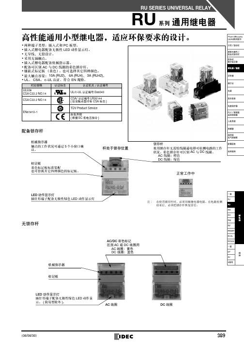
两种端子类型:插入式和 PC 板型。 插入式继电器配备无极性 LED 动作显示灯。 无导线,无铅设计。 采用无镉触点。 插入式继电器配备机械指示器。 配备可区别 AC 与 DC 线圈的彩色锁存杆。 。也可选择其它四种颜色。 镶嵌式标记板 (黄色) 最大触点容量: 10A (RU2)、 6A (RU4)、 3A (RU42)。 UL、 CSA、 c-UL 认证、符合 EN 规格。
双触点型
端子 锁存杆 标准型 配备锁存杆 RC 型 ( 仅限 AC 线圈 ) 二极管型 ( 仅限 DC 线圈 ) 二极管型 ( 仅限 DC 线圈 ) 反极性线圈 插入式端子 ( 注 1) 标准型 RC 型 ( 仅限 AC 线圈 ) 无锁存杆 二极管型 ( 仅限 DC 线圈 ) 二极管型 ( 仅限 DC 线圈 ) 反极性线圈 简易型 ( 注 2 ) PC 板端子 无锁存杆 简易型 ( 注 2 ) 注 1:除简易型外,在标准情况下插针形端子配备 LED 动作显示灯和机械指示器。 注 2:简易型无 LED 动作显示灯、机械指示器和锁存杆。 :请指定电压编码替换型号中的 。 型号 型号 4PDT RU42S- RU42S-R- RU42S-D- RU42S-D1- RU42S-C- RU42S-CR- RU42S-CD- RU42S-CD1- RU42S-NF- RU42V-NF- 线圈电压编码 A24、 A100、A110、 A200、 A220 D6、 D12、 D24、 D48、 D100、D110 A100、A110、 A200、A220 D6、 D12、D24、D48、 D100、 D110 D24 A24、 A100、 A110、 A200、 A220 D6、 D12、 D24、 D48、 D100、 D110 A100、 A110、 A200、 A220 D6、 D12、 D24、 D48、 D100、 D110 D24 A24、A100、 A110、 A200、 A220 D6、 D12、 D24、 D48、 D100、 D110
IDEC YW系列控制元器件 说明书
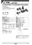
省空间的超薄型触点块分离式操控器部件令操作更加简便。
•体形小、重量轻。
•手指-安全型螺丝端子。
保护等级为 IP20(IEC60529)。
•组合式触点块令安装和拆卸更加方便。
•指示灯采用大灯罩,确保更广的视角和范围,增强安全性。
•按钮、灯罩和护罩均为不发光磨制表面,降低因周围光线引起的反光。
•
UL 、 c-UL 、 CCC 认证、符合 EN 标准。
•
UL508、 CSA C22.2 No. 14、 EN 60947-1、 EN 60947-5-1
触点容量(触点块)
规格
∗使用功率大于 1W 的灯时,应保留至少 50mm 的间距。
YW系列控制元器件ø22
YW系列控制元器件ø22
YW系列控制元器件ø22
YW系列控制元器件ø22
YW系列控制元器件ø22
YW系列控制元器件ø22
YW系列控制元器件ø22
123
YW系列控制元器件ø22
灯泡更换工具
金属安装孔塞
YW系列控制元器件ø22
YW系列控制元器件ø22
②①
②
YW系列控制元器件ø22。
idec ru2s-d24说明书

idec ru2s-d24说明书产品概述:IDEC的继电器、插座和定时器等产品品质、安全可靠,享有世界声誉。
有高达90A的逻辑级别控制产品,有各种脚线和安装方式的指示灯和检查按钮。
每一种继电器均符合端子管理的工业标准,IDEC的电子元器件比其他任何制造商的元器件产品都要优越。
常用型号RU2S-D24 RU2S-A220 RU2S-A24 RU2S-A110RU4S-D24 RU4S-A220 RU4S-A24RU4S-A110其他型号RU2S-* RU2S-R* RU2S-D* RU2S-D1*RU2S-C* RU2S-CR*IDEC的继电器、插座和定时器等产品品质、安全可靠,享有世界声誉。
有高达90A的逻辑级别控制产品,有各种脚线和安装方式的指示灯和检查按钮。
每一种继电器都符合端子管理的工业标准,IDEC的电子元器件比其他任何制造商的元器件产品都要优越。
主要特征:RU2:2电极、DPDT、10A/250V AC、10A/30V DCRU4:4电极、4PDT、6A/250V AC、6A/30V DC无焊接触点;无铅无镉触点;无内层电线。
自动标记指示器;色彩编码手动闭锁摇杆;即插入标志牌。
有12、24或110V DC;24、110-120、220-240V AC等可供选择备有翼片端子型和 PCB端子型。
标配无极性高亮度LED动作显示灯(仅翼片端子型)。
备有RoHS指令对应机种。
标配可确认触点动作状态的机械指示器(仅翼片端子型)。
配备可区别 AC 与 DC 线圈的彩色锁存杆。
镶嵌式标记板(黄色)。
也可选择其它四种颜色。
最大触点容量: RU2型10A、RU4型6A、RU42型3A。
UL、CSA、c-UL认证、符合EN标准。
技术参数品牌:IDEC和泉型号:RU2S-C-D24 封装:DIP批次:21+数量:888987 RoHS:是产品种类:电子元器件最小工作温度:-50C最大工作温度:100C最小电源电压: 1.5V最大电源电压:9.5V长度: 1.4mm宽度: 4.6mm高度: 1.2mm。
IDEC 继电器选择手册说明书

Relay Selection Guidean IDEC company2IDEC RelaysDIN rail mount, Panel mount, Interface and PCB mount RelaysDesigned with attention to every detail, IDEC relays are manufactured to ensure precision and quality. Our Industrial DIN rail mount, PCB mount and interface relays come in contact ratings from 6 Amps to 30 Amps for many applications. Correlating sockets include multiple features for ease-of-use and can also be DIN rail, panel or PCB mounted. Each socket is designed towork with IDEC timers and relays.Interface Relays• Use with PLC • 6mm and 14mm wide • 1 pole and 2 pole Page 3 & 4RJ Relays• 8 Amp and 12 Amp • 1 pole and 2 pole • Blade or PCB Terminals Page 5RH Relays• 1, 2, 3 and 4 pole • 10 Amp • Check button and indicator options Page 6RU Relays• 2 pole or 4 pole • 10 Amp Page 7RL Relays• 1 pole or 2 pole • 30 Amp• DIN rail or Panel mount Page 9RY Relays• Small signaling relay • 2 pole, 3 Amp• Blade plug-in or PCB terminals Page 9Force Guided Relays• EN Compliant • 2, 4, or 6 pole • Force guided contacts Page 10RV8H – L – AD110 – C1D2(when using combination ofRV1H relay and SV1H socket)D6: 6V DCD9: 9V DCD12: 12V DCD18: 18V DCD24: 24V DCAD12: 12V AC/DCAD18: 18V AC/DCAD24: 24V AC/DCAD48: 48V AC/DCAD60: 60V AC/DCAD110: 100-125V AC/DCAD220: 220V-240V AC/DCVoltage CodeTerminalsL: ScrewS: Spring ClampRatingBlank: StandardC1D2: Class I Division 2 RatingsHD: High Coil Voltage Dropout3• Space-saving 6mm width• Only 71mm in height from DIN rail• Gold-plated contacts• Pre-assembled relay and DIN rail mount socket• Class I Division 2 and Class I Zone 2 hazardous locations• Universal screw (flat and Phillips) or spring clamp terminals• Preprinted marking plates available• RoHS compliantScrew Terminals Spring Clamp Terminals4(when using combination ofRV1H relay and SV1H socket) RV8H – 1L1 – AD110 –C1D2D6: 6V DCD9: 9V DCD12: 12V DCD18: 18V DCD24: 24V DCAD12: 12V AC/DCAD18: 18V AC/DCAD24: 24V AC/DCAD48: 48V AC/DCAD60: 60V AC/DCAD110: 100-125V AC/DCAD220: 220V-240V AC/DCVoltage CodeTerminals1L1: 1 pole Screw Terminal2L: 2 pole Screw Terminal1S1: 1 pole Spring Clamp2S: 2 pole Spring ClampRatingBlank: StandardC1D2: Class I Division 2 RatingsHD: High Coil Voltage Dropout• Class I Division 2 and Class I Zone 2 hazardous locations• Space-saving 14mm width• Only 71mm in height from DIN rail• Gold-plated contacts• Pre-assembled relay and DIN rail mount socket• Universal screw (flat and Phillips) or spring clamp terminals• Preprinted marking plates available• RoHS compliantScrew Terminals Spring Clamp TerminalsRJ 22S – CL – A24Options C : Standard CL : LEDCD : Surge Suppression Diode*CLD : LED & Surge Suppression Diode* CH : High Capacity A : SPST-NO StandardAH: SPST-NO High CapacityContact Configuration 1: SPDT 2: DPDTTerminal S : Blade V : PCBA12: 12V AC A24: 24V AC A120: 120V AC A220: 220V AC A240: 240V ACD5: 5V DC D6: 6V DC D12: 12V DC D24: 24V DC D48: 48V DCD100: 100-110V DCVoltage Code ContactsBlank : Standard 2: Bifurcated***Diode is only for DC coils.**Bifurcated contacts available on DPDT relays only5• Compact size for maximum space savings on DIN rail• SPDT 12A and DPDT 8A contacts (high capacity 16A SPST-NO available)• Optional non-polarized, green LED • Locking and release lever on SJ sockets • RoHS compliantRJ Series - Slim Power RelaysRH 1B – UL AC24AC6AC12AC24AC120AC240DC6DC12DC24DC48DC110Coil Voltage Contact Configuration 1: SPDT 2: DPDT 3: 3PDT 4: 4PDTOptionsBlank : Standard Relay L : Indicator Light C : Check button T : Top Mounting*D : Diode (DC Coil Voltage Only)Terminal Type B : Blade (.187”)V2: PCB*Diode, Indicator light, and check button not available with top mount option1. For RH2B use AC110-120V2. For RH2B use AC220-240V3. For RH2B use DC100-110V6• Small, industrial 10A General Purpose relay • SPDT, DPDT, 3PDT, 4PDT contacts• Options: Indicator LED, check-button, top-mounting and surge-suppression diodes • DIN rail, through panel, and PCB-type sockets available• SPDT and DPDT 500K cycle UL tested for maximum life expectancy • RoHS compliantRH Series - Compact Power RelaysRU 2S – MD24Contact Configuration 2: DPDT 4: 4PDT42: 4PDT BifurcatedTerminals S : Blades V : PCBOptions(Blank): Standard (latchinglever & indicator light)C : No Latching LeverR : RC (AC coils only)NF : No Indicator Light, No Lever*D : Standard + Diode (DC coils only)M : Momentary Latching Lever* NF version only available with PCB terminalsA24: 24V AC A110: 120V AC A220: 24 0V AC D6: 6V DC D12: 12V DC D24: 24V DC D48: 48V DC D110: 110V DC Coil Voltage 7• DPDT 10A, 4PDT 6A and bifurcated 4PDT 3A contacts • Spot-welding technology eliminates internal wires and solder • Non-polarized, green LED• Color-coded, snap-on marking plates • RoHS compliantRU Series - Universal Relays8RR 1BA – U LAC120AC6AC12AC24AC120AC240DC6DC12DC24DC48DC110Coil Voltage Contact Configuration1: SPDT**2: DPDT3: 3PDTOptionsL: Indicator LightC: Check buttonLC: Indicator & Check buttonS: Side Flange* **Terminal TypeP: 8 Pin (DPDT )PA: 11 Pin (3PDT)B: Blade (3PDT)BA: Blade (SPDT, DPDT)* Indicator light and check button not available** Available in blade type only• Rugged, industrial 10A relay• SPDT, DPDT, 3PDT 10A contacts• Options: Indicator LED, check button and side-flange mounting• Round 8 and 11 pin base and square-blade base relays• Horsepower rated for small motors and solenoids• RoHS compliantRR Series - Power Relays***pin versions only• Double Make Form X contacts• Single pole rated at 30A, double pole at 25A • 3HP at 277V AC, 1.5HP at 120V AC• Flange mount or DIN rail mount with panel mount tabs • #250 quick-connect or screw terminations • AC or DC Coil Inputs• Designed for motor, lighting, and heater loads • RoHS compliantRL Series – Power RelaysRL 1B –T – A100Contact Configuration 1: 1 Form X 2: 2 Form XMounting T : Flange MountD : DIN rail Mount with panel mount tabsVoltageD : DC (Voltage: 12, 24V)A : AC 50/60Hz(Voltage: 24, 100-120, 200-240V)TerminalsB : Quick Connect Terminal N : Screw TerminalInput Volatage 12: 12V 24: 24V100: 100-120V 200: 200-240V9RY 2S –U L AC24VAC6V AC12V AC24V AC120V AC240VDC6V DC12V DC24V DC48V DC110VCoil Voltage Contact Configuration 2: DPDTOptionsL : Indicator Light C : Check button T : Top Bracket*D : Diode**Terminal Type S : Blade (.110”)V : PCB* Diode, indicator light, and check button not available ** Diode for DC coils only• Small, industrial General Purpose signaling relay • DPDT 3A,• Options: Indicator LED, check-button and surge-suppression diode • Plug-in/solder and PCB terminals • RoHS compliantRY Series - Miniature RelaysRF2S – 1A1BLD1 K – D24Terminal Style S : Plug-in V : PC BoardOptionBlank : Standard L : With LED Indicator D : With DiodeD1: With Diode of reverse polarity coilLD : With LED Indicator & Diode LD1: With LED Indicator & Diode of reverse polarity coilDegree of Protection Blank : RTII K: RTIIIRated Coil Voltage D12: 12V DC D24: 24V DC D48: 48V DCSeriesNo. of Poles2: 2-PoleContact Configuration 1A1B : SPST-NO + SPST-NC 2C : DPDTRF1V – 2A2BL – D48Contact Configuration 2A2B : 4-Pole, 2NO-2NC 3A1B : 4-Pole, 3N0-1NC 4A2B : 6-Pole, 4NO-2NC 5A1B : 6-Pole, 5NO-1NC3A3B : 6-Pole, 3NO-3NCLED Indicator Blank : No Indicator L : LED IndicatorLD1: Counter-EMF Diode and LED IndicatorCoil Voltage D12: 12V DC D24: 24V DC D48: 48V DC10• Compact and EN compliant Force-Guided relays• Force-guided contact mechanism (EN50205 Type A TÜV approved)• Contact configuration:4-pole (2NO-2NC, 3NO-1NC)6-pole (4NO-2NC, 5NO-1NC, 3NO-3NC)• Built-in LED indicator available• Built-in Counter-Electromotive Force Diode and LED indicator available • RoHS compliant• 2-Pole Force-Guided relay contact mechanism (EN50205 Type A TUV Approved)• Mechanical indicator shows contact status• RTIII degree of protection, LED indicator and Diode models available • Can be used with SJ Series SocketsRF1V Series - Force-Guided 4-Pole and 6-Pole RelaysRF2V/RF2S Series – Force-Guided 2-Pole Relays11• Gold-plated contacts• 6A contact rating on 6mm RV1H, 8A on RV2H-1HG1, 16A rating on RV1H-2G• Operating temperature of -40ºC ~ 70°C • RoHS compliant• RJ Slim GP Relay ideal for space-saving application • Compact size: 12.7 x 25.5 x 28.8mm • Long electrical life and mechanical life• Electrical life: 200,000 cycles (AC Load) and 100,000 cycles (DC Load)• Mechanical life: 30 million cycles (AC coil) and 50 million cycles (DC coil)• RoHS complaint (2002/95/EC)Printed Circuit Board Mount Relays - (PCB Mount)RV1H Series – Interface RelaysRJ Series - PCB Mount RelaysContact Configuration G : SPDT (6mm)2G : SPDT (14mm)1HG1: DPDT (14mm)RV1H – 1HG1 –D12Coil Voltage D5: 5V DC D6: 6V DC D9: 9V DC D12: 12V DCContact Configuration C : FORM C(DT Double Throw)A : FORM A(ST Single Throw)RJ1 V – C – HD24Contact Configuration Blank : Standard H : High Capacity Type (RJ1 only)Number of Poles 1: SP(Single Pole)2: DP(Double Pole)Relay Width RV1H : 6mm RV2H : 14mmCoil Voltage D5: 5V DC D6: 6V DC D12: 12V DC D24: 24V DC D48: 48V DCD100: 100-110V DC A24: 24V AC A120: 120V AC A240: 240V ACD18: 18V DC D24: 24V DC D48: 48V DC D60: 60V DC D110: 110V DC12• Choice of 20A, 30A and 45A models• Slim design allows for compact DIN rail or panel mounting • Built-in heat sink• Epoxy-free design and improved thermal impedance • LED indicator• Finger-safe terminals • Zero voltage switching• Current ratings up to 90A at 660V AC • AC (90-280V) or DC (4-32V) input • Input current regulated 10mA• Photo isolation of input and output (up to 4000V) • Zero voltage turn on• Dual SCR output with built-in snubber• Long electrical life• Pre-assembled relay and DIN rail mount socket • Built-in LED indicator• Screw and spring-clamp socket terminations • Operating temperature: -20 to +70C • RoHS compliantRSC Series – Solid State RelaysRSS Series – Solid State RelaysRV8S Series – Solid State Interface RelaysInput VoltageA1N : AC (90-140V AC)A2N : AC (180-280V AC)DN : DC (4-32V DC)RSC A1N – 10AContinuous Output Current 20A : 20 Amp 30A : 30 Amp 45A : 45 AmpInput Voltage AN : 90-280V AC DN : 3-32V DCRSS AN – 10AContinuous Output Current 10A : 10 Amp 25A : 25 Amp 50A : 50 Amp 75A : 75 Amp 90A : 90 AmpOutput Voltage D24: 24V DC D48: 48V DC A240: 240V ACA240Z : 240V AC Zero CrossingRV8S – L –D24 – D24Input Voltage 6V : 6V DC 24V : 24V DC 120V : 120V AC 240V: 240V ACTerminal L : ScrewS : Spring Clamp1314IDECRR2PRR3PARU2SRU4SRR2BARR3BRQ1V-CMRQ1V-CHRQ2V-CNRV8H-L-D24RV8H-L-D12RV8H-L-D24RV8H-L-AD110RV8H-L-AD220RV8H-S-D12RV8H-S-D24RV8H-S-AD110RV8H-S-AD220RV1H-G-D12RV1H-G-D24RV1H-G-D60SQ1V-07BSQ2V-07BSR2P-06SR3P-06SM2S-05SY4S-05SY4S-61SV1H-07L-1SV1H-07L-3SV1H-07L-4SV1H-07LS-1SV1H-07LS-3SV1H-07LS-4IDECRV8H-L-D6RV8H-L-D12RV8H-L-D24RV8H-L-AD24RV8H-L-AD110RV8H-L-AD220RSS113012 12Vdc-Rel1U RV1H-G-D12RSS113024 24Vdc-Rel1U RV1H-G-D24RSS112060 60Vdc-Rel1U RV1H-G-D60SV9Z-J20*SV9Z-PW16SV9Z-PW16SV9Z-J20**Indicates additional digits required to complete part number.Note that operating differences may occur between “crossed” parts.Note: The cross references listed are the closest match physically and functionally. If you are looking to match a specific application requirement, please refer to our Industrial Automation Catalog. Foran IDEC company30 COMPANIES75 YEARS OF EXPERIENCE3,780 EMPLOYEES WORLDWIDE 100 000 + REFERENCESBENELUXBelgicastraat 7/11930 ZAVENTEM BelgiumBEL: (+32) 27 25 05 00NL: (+31) (70) 799 91 51 be.sales@FRANCE55, avenue Edouard Herriot BP182303 CAUSSADE Cedex (+33) 5 63 93 14 98mercial@GERMANYGewerbehof Giesing Paulsdorfferstr. 34, 2. OG D-81549 MUNICHMUNICH: (+49) 89 45 99 11 0 HAMBURG: (+49) 40 253054 0info@apem.deITALYVia Marconi 147G 12030 MARENE (CN)(+39) 0172 74 3170apem.italia@SWEDENTorshamnsgatan 39S-16440 KISTA (+46) 8 626 38 00info@apem.seUNITED KINGDOM Drakes DriveLONG CRENDON, Bucks HP18 9BA England(+44) 1 844 202400sales@To receive our latest news, subscribe to our bimonthly newsletter: https://bit.ly/3x06NgEFollow us on Linkedin Follow us on YoutubeI D E C r e s e r v e s t h e r i g h t t o a m e n d s p e c i f i c a t i o n s w i t h o u t n o t i c e - D e s i g n E 3 C r éa - P h o t o s : i S t o c k / S h u t t e r s t o c k / j o j o ’n c o - E D I T E D I N A U G U S T 2021Contact our safety specialists at eu.support@5。
和泉 继电器 RJ系列SJ系列(中文版)

5A !
ณதլ)ࢲဣ၂ক၂*
ACത
DCത
3000 ཆ״ჾණ
5000ཆ״ჾණ
ᆢཛྷوದ3ຓӂާ๖
1000ᦎѨ
ᆢཛྷوದ2ຓ.5ާӂ๖
2000ᦎѨ
RJ1 ದຓާ๖դ౹
RJ2 ದຓާ๖դ౹
ኢǖ! ದຓާ๖դ౹وӔृཛྷդ౹Ⴥӊණຑࣝᆾืو
RJ ದຓާ๖RդJ ౹ ದຓާ๖դ౹
注 :请指定电压编码代替型号中的ˎɻ
❏触点容量
极数
触点
触点最大允许容量 电阻性负载 电感性负载
单极 双极
3,000VA AC 1,875VA AC
NO
360W DC
180W DC
3,000VA AC 1,875VA AC
NC
180W DC
90W DC
2,000VA AC 1,000VA AC
NO
240W DC
❏最大开闭容量
• RJ1S型
250V AC٫የ၂ݘᆾ 30V DC٫የ၂ݘᆾ)NO٧*
12
• RJ2S型
500
100
ෳ
ᅋ
ณ
A12ɺA24ɺA110ɺ A115ɺA120ɺA220ɺ A230ɺA240 D5ɺD6ɺD12ɺD24ɺ D48ɺD100
RJ2S-CLD-ˎ
RJ2S-CD-ˎ RJ2S-CLD1-ˎ
D5ɺD6ɺD12ɺD24ɺ D48ɺD100
RJ2S-CD1-ˎ
RJ2S-CLR-ˎ RJ2S-CR- ˎ
A12ɺA24ɺA110ɺ A115ɺA120ɺA220 A230ɺA240
RJ 系列 薄型功率继电器 SJ 系列 继电器插座
和泉IDEC安全继电器 HR1S-AF5130使用说明书

开关 · 指示灯 (方孔) 表面安装型 LED 指示灯 LUMIFA LED 照明单元 组合式 数字显示器
安全元器件 1
• HR1S-AF5130PB 型(端子部可拆装型)
A1/A2 Fuse K1 K2
99
安全元器件 2
端子台 继电器 · 定时器 · 插座 电路保护器
电源 PLC · SmartRelay 人机界面
HS1C-K
一览
安 HR1S-ATE 全
继 HR1S-AC 电
器 HR1S-AF 模
块
HR1S-AK
一览
安 全
控
FS1A
制 器
一览
安
全
光
SE4B 幕
一览
多 层
警
LD6A
示 灯
2010-12-28
773
HR1S-AC 型 安全继电器模块
❏HR1S-AC 型 安全继电器模块接线图例
• 安全类别对应电路例(使用紧急停止开关) 使用 2 个 NC 触点的紧急停止开关(推荐 :相当于安全类别 3)
• 电源线外部保险丝请使用 4A 保险丝(gG(gL)型)。 • 输出线外部保险丝请使用 4A 保险丝(gG(gL)型),或 6A 速断型保险丝。
❏外形尺寸图(mm)
• HR1S-AF5130B 型
A1/A2 Fuse K1 K2
22.5
114
99
Flush Silhouette
开关 · 指示灯 (圆孔)
晶体管电路
24V/20mA
最小负载
17V/10mA(初始值)
操作频率
1,200 次/小时以下
额定通电电流 连接电线尺寸 重量(约)
IDEC RY系列小型继电器 说明书

DPDT
AC: cos ø = 1.0, DC: L/R = 0 ms
• UL 标准额定值 ( 双分叉触点 )
电压 240V AC 120V AC 30V DC 电阻 0.8A 1A 1A 通用 0.4A 0.5A 0.5A
• CSA 标准额定值 ( 双分叉触点 )
电压 240V AC 120V AC 30V DC 电阻 0.8A 1A 1A 通用 0.4A 0.5A —
DC6、DC12、DC24、DC48、 DC100-110 AC6、AC12、 AC24、AC50、 AC100-110、AC110-120、 AC200-220、AC220-240 DC6、DC12、DC24、DC48、 DC100-110 DC6、DC12、DC24、DC48、 DC100-110
240V AC 30V DC 5A 0.2A 1.5A DPDT 3A 3A 4PDT 5A 5A 4PDT
电阻
DPDT 3A — 0.2A 3A 4PDT 5A — 0.2A 5A 0.8A 1.5A 0.2A 3A
DPDT
电压
240V AC 120V AC 100V DC 30V DC
电阻
DPDT 3A 3A — 3A — 5A 4PDT 5A 0.8A 1.5A 0.2A 1.5A
DPDT 4PDT
型号 RY2S-U∗ RY2S-UL∗ — — RY2S-UT∗ RY2S-UD∗ — RY22S-U∗ RY22S-UL∗ RY22S-UT∗ RY22S-UD∗ ★ ★ ★ ★ ★ ★ ★ ★
线圈电压编码 ∗
型号 RY4S-U∗ ★ ★ ★ ★ ★ ★ ★ ★ ★ ★ ★
线圈电压编码 ∗ AC6、AC12、 AC24、AC50、 AC100-110、AC110-120、 AC200-220、AC220-240 DC6、DC12、DC24、DC48、 DC100-110
WRG 中间继电器 主流品牌型号对照表(详细版) 20161220

——
——
——
35 RMIE-248DTL
G2R-2-SNI DC48(S) RXG22ED
DRI 424048LT
——
——
——
36 RMIE-2110DTL G2R-2-SNI DC110(S) RXG22FD
DRI 424110LT
——
——
——
37 RMIE-212ATL
G2R-2-SNI AC12(S) ——
24 RL-4380AL
欧姆龙/OMRON MY2N-GS DC12 MY2N-GS DC24 —— MY2N-GS D48 MY2N-GS D110 MY2N-GS D220 MY2N-GS AC12 MY2N-GS AC24 MY2N-GS AC48 MY2N-GS AC110 MY2N-GS AC220 MY2N-GS AC380 MY4N-GS DC12 MY4N-GS DC24 —— MY4N-GS D48 MY4N-GS D110 MY4N-GS D220 MY4N-GS AC12 MY4N-GS AC24 MY4N-GS AC48 MY4N-GS AC110 MY4N-GS AC220 MY4N-GS AC380
RM2S-UL DC100-110 ——
RM2S-UL DC220-240 ——
RM2S-UL AC12
——
RM2S-UL AC24
——
RM2S-UL AC48
——
RM2S-UL AC110-120 ——
RM2S-UL AC220-240 ——
——
——
RY4S-UL DC12
——
RY4S-UL DC24
主流品牌型号对照表
注释:因各品牌的产品各有特点,这里给出的是主流型号选型对照,仅供参考。 详细的替换选型请查阅各品牌产品样本,或咨询WRG。
日本idec和泉AL8M-M11R系列照明按钮开关

A8 系列 小型控制元器件 ø25
明亮鲜明的照光面、轻盈舒
适 的 操 作 感。 胴 长 22mm
一体型 ø8 系列。
• 高效率背面端子接线方式、全系列长度均为 22mm 的翼片端子。 • UL、CSA 认证。
对应标准 UL508
认证标志
认证机构/认证编号
Flush Silhouette
请按订购型号订购 开关 · 指示灯
(圆孔)
请使用下列颜色编码替换型号中的 ∗ R :红色、 G :绿色、Y :黄色、 A :琥珀色、W :乳白色
AB8Q-M1∗ AB8Q-A1∗
请使用下列颜色编码替换型号中的 ∗ B :黑色、R :红色、G :绿色、 Y :黄色、S :蓝色、W :白色
AB8Q-M1L∗ AB8Q-A1L∗
请使用下列颜色编码替换型号中的 ∗ R :红色、 G :绿色、Y :黄色、 A :琥珀色、W :乳白色
使用电压和限制外部电流用电阻 (推荐值)(注)
内部电路
LAD-SR
LAD-SG
LAD-SA
A 系列专用
20mA
1.7V
2.1V
2.2V
4V
R :红色
G :绿色
A :琥珀色
红色透明
黄色扩散
琥珀色透明
R(红色)用
G(绿色)用
A(琥珀色)用
红色
约 50,000 小时(在 25˚C 环境下的完全直流点灯,亮度减弱为初始值的 50% 时)
5V DC :150Ω、1/2W 6V DC :200Ω、1/2W 12V DC :510Ω、1W 24V DC :1.1kΩ、1W
(+)
(-)
RU继电器

∗5
简易型 :- 55 ~+ 70(无结冰) 其他 :- 55 ~+ 60(无结冰)
5 ~ 85%RH(无结露)
35g
RQ
RU
继
电
RR
器
电压
电阻
电感
RU2 RU4 RU42 RU2 RU4 RU42
250V AC 10A 6A 3A 5A 0.8A 0.8A
30V DC 10A 6A 3A 5A 1.5A 1.5A
250V AC 10A - - - 6A 3A - 1/10HP -
30V DC 10A 6A 3A - - - - - -
• CSA 标准额定值
电压
电阻
一般用途
马力额定值
RU2 RU4 RU42 RU2 RU4 RU42 RU2 RU4 RU42
250V AC 10A - - - 6A 3A - 1/10HP -
开关 · 指示灯 (方孔) 表面安装型 LED 指示灯 LUMIFA LED 照明单元 组合式 数字显示器
安全元器件 1
安全元器件 2
端子台
继电器 · 定时器 · 插座
电路保护器
电源
PLC · SmartRelay
人机界面
传感器
防爆设备
各种资料
LED 指示灯
翼片端子配备无极性绿色 LED 动作指示灯。
线圈电阻(Ω) ±10%(20ºC)
164 3,460 4,550 14,080
动作特性(在 20ºC 时相对于额定值)
最大允许电压
最小启动电压
释放电压
110%
80% 以下
30% 以上
Flush Silhouette
开关 · 指示灯 (圆孔)
IDEC RJ Series Slim Power Relays 产品说明书

RJ Series736S w i t c h e s & P i l o t L i g h t sD i s p l a y L i g h t sT i m e r sT e r m i n a l B l o c k sC i r c u i t B r e a k e r sRelays & SocketsR J SeriesS lim Power Relays Compact and rugged power relays. Large switching capacity.Compact housing only 12.7-mm wide.Large contact ratingRJ1 (1-pole): 16A (UL general use rating @250V AC)RJ2 (2-pole): 8ANon-polarized LED indicator available on blade type. IDEC’s unique light guide structure enables high visibility of coil status from any direction.Excellent electrical and mechanical life.Electrical life: 200,000 operations (AC load)Mechanical life: 30 million operations (AC coil)RoHS directive compliant (EU directive 2002/95/EC). Contains no lead, cadmium, mercury, hexavalent chromium, PBB or PBDE).Diode model:Diode reverse withstand voltage: 1000V UL recognized, CSA certifi ed, EN compliant.UL508UL File No. E55996CSA C22.2 No. 141608322CSA File No. LR35144Reg.-Nr. B312EN61810-1VDE (REG.-Nr B312)EN61810-1EC Low Voltage DirectiveP art Number Selection••••••*Hold-down clip or spring must be removed to use with RJ PCB relays.737USA: 800-262-IDEC Canada: 888-317-IDECRJ Series738S w i t c h e s & P i l o t L i g h t sD i s p l a y L i g h t sT i m e r sT e r m i n a l B l o c k sC i r c u i t B r e a k e r sRelays & Sockets1. LED Indicator is only available on Blade relays.2. Operating characteristics are at 20ºC.3.The maximum allowable voltage is the maximum value which can be applied to the relay coils.*According to the utilization categories of IEC60947-5-1RJ Series740S w i t c h e s & P i l o t L i g h t sD i s p l a y L i g h t sT i m e r sT e r m i n a l B l o c k sC i r c u i t B r e a k e r sRelays & SocketsOperating Temperature and Coil Temperature RiseRJ1 (AC Coil, 60 Hz)RJ1 (AC Coil, 50 Hz)RJ1 (DC Coil)T e m p e r a t u r e R i s e (°C )Ambient Temperature (°C)T e m p e r a t u r e R i s e (°C )Ambient Temperature (°C)T e m p e r a t u r e R i s e (°C )Ambient Temperature (°C)RJ2 (AC Coil, 60 Hz)RJ2 (AC Coil, 50 Hz)RJ2 (DC Coil)T e m p e r a t u r e R i s e (°C )Ambient Temperature (°C)AC Coil (50 Hz)T e m p e r a t u r e R i s e (°C )Ambient Temperature (°C)T e m p e r a t u r e Ri s e (°C )Ambient Temperature (°C)The above temperature rise curves show characteristics when 100% the rated coil voltage is applied.The slanted dashed line indicates allowable temperature rise for the coil at different ambient temperatures.Internal Connection (View from Bottom)RJ1S-C-* StandardRJ2S-C-* StandardRJ1S-CL-* With LED IndicatorRJ2S-CL-* With LED IndicatorCoil voltage greater than 24V AC/DCCoil voltage 24V AC/DC and belowCoil voltage 24V AC/DC and below Coil voltage greater than 24V AC/DCRJ1S-CD-* With DiodeRJ2S-CD-* With DiodeRJ1S-CLD-* With LED Indicator and DiodeRJ2S-CLD-* With LED Indicator and DiodeCoil voltage 24V DC and below Coil voltage greater than 24V DCCoil voltage 24V DC and below Coil voltage greater than 24V DC741 USA: 800-262-IDEC Canada: 888-317-IDECRJ Series742S w i t c h e s & P i l o t L i g h t sD i s p l a y L i g h t sT i m e r sT e r m i n a l B l o c k sC i r c u i t B r e a k e r sRelays & SocketsDimensions con’t (mm)Standard DIN Rail Mount Sockets SJ1S-05BSJ2S-05B51234(A1)(12)(A2)(14)(11)(TOP VIEW)81275643(A1)(A2)(22)(12)(14)(11)(21)(24)(TOP VIEW)Finger-safe DIN Rail Mount Sockets SJ1S-07LSJ2S-07L(TOP VIEW)SQ1V-07B SQ2V-07B1114A2A1(TOP VIEW)12241412(TOP VIEW)112221A2A1743 USA: 800-262-IDEC Canada: 888-317-IDECOperating Instructions774S w i t c h e s & P i l o t L i g h t sD i s p l a y L i g h t sT i m e r sT e r m i n a l B l o c k sC i r c u i t B r e a k e r sRelays & SocketsO perating InstructionsDriving Circuit for Relays1. To ensure correct relay operation, apply rated voltage to the relay coil.2. Input voltage for the DC coil:A complete DC voltage is best for the coil power to make sure of stable relay operation. When using a power supply containing a ripple voltage, suppress the ripple factor within 5%. When power is supplied through a rectifi cation circuit, the relay operating characteristics, such as pickup voltage and dropout voltage, depend on the ripple factor. Connect a smoothing capacitor for better operating characteristics as shown below.Ripple Factor (%)× 100%Emax – EminEmax = Maximum of pulsating current Emin = Minimum of pulsating current Emean = DC mean valueEmean3. Leakage current while relay is off:When driving an element at the same time as the relay operation, special consideration is needed for the circuit design. As shown in the incorrectcircuit below, leakage current (Io) fl ows through the relay coil while the relay is off. Leakage current causes coil release failure or adversely affects the vibration resistance and shock resistance. Design a circuit as shown in the correct example.4. Surge suppression for transistor driving circuits:When the relay coil is turned off, a high-voltage pulse is generated, causing a transistor to deteriorate and sometimes to break. Be sure to connect a diode to suppress the back electromotive force. Then, the coil release time becomes slightly longer. To shorten the coil release time, connect a Zener diodebetween the collector and emitter of the transistor. Select a Zener diode with a Zener voltage slightly higher than the power voltage.Back emfProtection for Relay Contacts1. The contact ratings show maximum values. Make sure that these values are not exceeded. When an inrush current fl ows through the load, the contact may become welded. If this is the case, connect a contact protection circuit, such as a current limiting resistor.2. Contact protection circuit:When switching an inductive load, arcing causes carbides to form on the contacts, resulting in increased contact resistance. In consideration of contact reliability, contact life, and noise suppression, use of a surge absorbing circuit is recommended. Note that the release time of the load becomes slightly longer. Check the operation using the actual load. Incorrect use of a contact protection circuit will adversely affect switching characteristics. Four typical examples of contact protection circuits are shown in the following table:3. Do not use a contact protection circuit as shown below:Generally, switching a DC inductive load is more diffi cult than switching a DC resistive load. Using an appropriate arc suppressor, however, will improve the switching characteristics of a DC inductive load.Soldering1. When soldering the relay terminals, use a soldering iron of 30 to 60W, and quickly complete soldering (within approximately 3 seconds).2. Use a non-corrosive rosin fl ux.775 USA: 800-262-IDEC Canada: 888-317-IDEC。
IDEC-FC5A系列说明书
非常感谢您购买IDEC 的产品。
请确认订购的产品无误后,仔细阅读本使用说明书及FC5A 用户手册,以便正确使用。
此外,请用户妥善保管本使用说明书。
MicroSmart 扩展接口模块是扩展FC5A 的I/O 数量的模块。
一般FC5A CPU 模块最多可连接7个模块,但使用扩展接口模块可再连接8个模块。
本产品根据用途的不同,分为一体型和电缆导出型2种。
扩展接口模块与FC5A 超薄型CPU 模块(FC5A-D32K3, FC5A-D32S3, FC5A-D16RK1, FC5A-D16RS1)相连接。
请先确认型号后再使用。
(请注意本产品不支持FC5A 集成型CPU 模块、FC4A 超薄型及FC4A 集成型。
)使用说明书F C 5A 系列模块名扩展接口模块(一体型)扩展接口模块(电缆导出型主机)扩展接口模块(电缆导出型从机)通信电缆(1.0m)型号FC5A-EXM2FC5A-EXM1M FC5A-EXM1S FC5A-KX1C详细一体型电缆导出型请在同一电源中使用CPU模块与扩展接口模块。
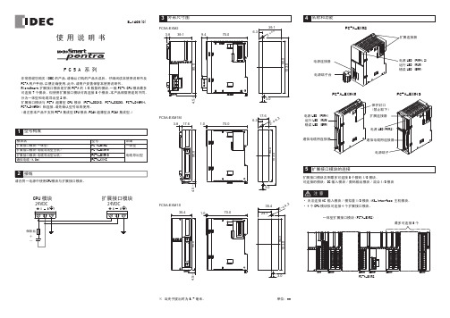
CPU 模块扩展接口模块FC5A-EXM2FC5A-EXM1M103.017.63.870.01.017.66.32-φ4.390.03.090.04.5※FC5A-EXM1S35.42-φ4.3103.090.035.41.070.024.190.04.5※3.024VDC+-90.039.13.870.09.439.16.32-φ4.33.090.04.5※103.0※ 当夹子拔出时为8.5毫米。
単位:mm扩展接口模块右侧最多可连接8个数码I/O 模块。
可连接的模块:DC 输入模块/数码输出模块/混合I/O 模块一体型扩展接口模块(FC5A-EXM2)电源LED (PWR1,2)运行LED (RUN)错误LED (ERR)扩展连接器FC5A-EXM2通信电缆用连接器FC5A-EXM1SFC5A-EXM1M电源端子电源LED(PWR2)扩展连接器通信电缆用连接器电源端子台电源连接器FC5A-EXM2最多可连接8个B-1498(0)电源LED (PWR1)运行LED (RUN)错误LED (ERR)保护封口(禁止取下)· 无法连接AC 输入模块/模拟量I/O 模块/AS-Interface 主机模块。
Plug_in_Relay_中间继电器_CN

金属压紧扣具 (每 100 个包装) 标签 (每 100 个包装)
Zelio Relay系列中间继电器产品分析及中国市场营销 — LEC事业部市场部 — 2003.7
5
附表一: 继电器选型对照表
继电器:
RXL 2
A12 B1 BD
线圈电压
BD:DC24V; JD: DC12V; ED:DC48V; FD :DC110V
RZM031FPD 二极管带指示灯 继电器线圈电压为 DC: 110-230V
RZM021RB 变阻器带指示灯 继电器线圈电压为 DC 或 AC: 6-24V
RZM021BN 变阻器带指示灯 继电器线圈电压为 DC 或 AC: 24-60V
RZM021FP 变阻器带指示灯 继电器线圈电压为 DC 或 AC: 110-230V
手动测试按键功能 调试便利 维护便利
可视化设计 色彩标识
• 红色按键表示交流 • 绿色按键表示直流
视窗、标签位设计
可选配功能附件 由用户灵活、自由选择
3
产品分析
—— 基座
国际产品
意大利制造,全球销售 UL、CSA认证
可靠性高
压铸工艺制造 额定电流大,可达12A 防护等级为IP20
主要型号 原=S= RXN 系列
RXL2A12B1BD RXN21E11BD RXL2A12B1P7 RXN21E11P7 RXL2A12B2BD RXN21E12BD RXL2A12B2P7 RXN21E12P7 RXL3A10B1BD RXL3A10B1P7 RXL3A10B2BD RXL3A10B2P7 RXL4A06B1BD RXN41G11BD RXL4A06B1P7 RXN41G11P7 RXL4A06B2BD RXN41G12BD RXL4A06B2P7 RXN41G12P7
双电压自动切换继电器
第5页,共15页 版权所有,侵权必究
RUS-32A(B)双电压自动切换继电器产品说明书
3. 面板描述
密级:机密
第2页,共15页 版权所有,侵权必究
修订记录 版本号 发布日期 V1.0 2010-09-02
拟制人
贾文
首次发布
修订描述
第3页,共15页 版权所有,侵权必究
RUS-32A(B)双电压自动切换继电器产品说明书
密级:机密
1. 产品概述
1.1 适用范围 电力工程的实际使用过程中,供给保护装置直流电源大量采用蓄电池供电。为了保护装置的
南京澳德思电气有限公司
RUS-32A(B)双电压自动 切换继电器产品说明书 (V1.0)
(RD-ENG-T14 V2.0 2008-06-06) 南京澳德思电气有限公司 版权所有
第1页,共15页 版权所有,侵权必究
目录
修订记录.................................................................................................................................... 3 1. 产品概述 ......................................................................................................................................... 4 1.1 适用范围 ......................................................................................................................... 4 1.2 产品特点 ......................................................................................................................... 4 1.3 型号及命名规则 ............................................................................................................. 4 2. 主要技术参数 ................................................................................................................................. 5 2.1 额定参数 ......................................................................................................................... 5 2.2 绝缘性能 ......................................................................................................................... 5
idec继电器原理
idec继电器原理
IDEC(瑞士爱迪克公司)是一家生产继电器、控制器和工业自动化设备的公司。
IDEC继电器的工作原理与一般继电器的工作原理相似,以下是一般继电器的工作原理,也适用于IDEC继电器:
1.电磁线圈:IDEC继电器包括一个电磁线圈,通常由绕制在铁
芯上的绕组组成。
当电流通过这个线圈时,它会在铁芯上产生
一个磁场。
2.吸引铁片:铁芯的磁场会吸引一个铁片(也称为吸引子或吸铁
片),这个铁片通常连接到继电器的触点。
3.触点:IDEC继电器内部包含一个或多个触点。
当铁片被吸引
时,触点会闭合,建立一个电路,允许电流流经继电器的通路。
这通常用于控制其他电气设备,如电机、灯、阀门等。
4.释放铁片:当电流通过电磁线圈停止,铁片将不再被吸引,它
会返回到初始位置。
这导致触点分离,中断电路。
总之,IDEC继电器的工作原理是基于电磁吸引力的。
当电流通过继电器的电磁线圈时,产生的磁场会吸引铁片,使触点闭合,从而建立电路。
一旦电流停止,铁片返回原位,触点分离,中断电路。
这种操作可用于控制和开关其他电气设备,从而实现自动化和控制功能。
IDéc继电器通常用于工业和商业应用中,以执行各种控制任务。
IDEC 开关资料
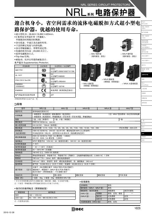
型号说明❏NRLT 型(摇杆型)NRL 系列 电路保护器NRLR型(翘板型)〔螺丝安装型〕•NRL系列电路保护器内部电路❏过电流-时间特性表(秒·在25℃时)❏脱扣动作特性(在25℃时)❏10001001010.10.01动作时间︵秒︶电流(对于额定电流的%)10001001010.10.01动作时间︵秒︶电流(对于额定电流的%)10001001010.10.01动作时间︵秒︶电流(对于额定电流的%)注:在带★记号的脱扣动作特性中备有惯性延迟型。
NRL 系列 电路保护器各种安装方向的额定电流(跳闸电流值)的变化❏过电流脱扣机构为完全电磁型。
最小动作电流值在可动铁心重量的影响下,随安装形态而变化。
请以右图为基准,在修正额定电流后再使用。
注1:安装方向不影响额定电流值。
注2:最小动作电流的修正值由下式计算:最小动作电流修正值=额定电流值×135%×各种安装方向的修正率端子间电阻(Ω)100%外形尺寸图(mm )❏NRLT 型(摇杆型)OFFONLINELOAD1极:36.616.8423616.825332.530°5.085.08272.224t0.4mmN PM12122极 :33.6镶嵌面六角螺帽 (对边14)主端子(6.4W ×0.8t )250型翼片端子ø15串联跳闸 · 开关专用继电器跳闸(4端子)辅助触点端子注:前面和背面图的虚线部分为2极型的尺寸图。
NRLP 型(摇杆型·PCB 用端子)0.82M12ONOFF123343.544.12516.842.91.2530°3.50.812.61.2LOAD 端子PCB 42.95.045.085.0827.8主体固定用主端子LOAD 侧2-ø1.90.1孔3-ø1.20.1孔4-ø1.90.1孔镶嵌面辅助触点端子辅助触点端子(辅助触点端子)(底视图)LINE 端子LINE 侧0.6NP9.20.836.627.85.085.0812.617.6NRL 系列电路保护器注:导线长度:约100mm0.88.91027.016.829主端子250型翼片端子注:导线长度:约100mmNRLK 型(大型翘板型) 注:前面和背面图的虚线部分为2极型尺寸图。
- 1、下载文档前请自行甄别文档内容的完整性,平台不提供额外的编辑、内容补充、找答案等附加服务。
- 2、"仅部分预览"的文档,不可在线预览部分如存在完整性等问题,可反馈申请退款(可完整预览的文档不适用该条件!)。
- 3、如文档侵犯您的权益,请联系客服反馈,我们会尽快为您处理(人工客服工作时间:9:00-18:30)。
线圈额定电压 6V DC 12V DC 24V DC 48V DC 100V DC 110V DC
❏附件
名称
订购型号
最小起订数量
盒装表示型号
标记板
RU9Z-P✽
1 盒(10 个)
RU9Z-P✽PN10
• 订购时,请指定颜色记号替换型号中的 ✽。 可将一字形螺丝刀从继电器侧面拆卸标记板。
RJ系列 功率继电器 双触点型
RJ-PCB 系列 功率继电器 双触点型
RJ 系列 功率继电器
RJ-PCB 系列 功率继电器
RU 系列 继电器
RL 系列 功率继电器
RR 系列 功率继电器
LED 指示灯
翼片端子配备无极性绿色 LED 动作指示灯。
❏无锁存杆型
机械式指示器 标记板
注 :使用锁存杆前,应先切断电源。检查动作之后, 应将锁存杆推回原来位置。
标准型
RU42S-R-✽ RU42S-D-✽ RU42S-D1-✽
RU42S-C-✽
无锁存杆
RC 型(仅限 AC 线圈) 顺极性二极管型(仅限 DC 线圈)
逆极性二极管型(仅限 DC 线圈)
PCB注 2) (注 2)
• 请指定使用电压记号替换型号中的 ✽。 注 1 :除简易型外,翼片端子标准配备 LED 指示灯及机械式指示器。 注 2 :简易型无 LED 指示灯、机械式显示指示器及锁存杆。
RU42S-CR-✽ RU42S-CD-✽ RU42S-CD1-✽ RU42S-NF-✽ RU42V-NF-✽
最小起订数量 :1 个
线圈电压编码 ✽
A24、A100、A110、A200、A220 D6、D12、D24、D48、D100、D110 A100、A110、A200、A220 D6、D12、D24、D48、D100、D110 D24 A24、A100、A110、A200、A220 D6、D12、D24、D48、D100、D110 A100、A110、A200、A220 D6、D12、D24、D48、D100、D110 D24 A24、A100、A110、A200、A220 D6、D12、D24、D48、D100、D110
标准型
RU2S-R-✽ RU2S-D-✽ RU2S-D1-✽
RU2S-C-✽
RU4S-R-✽ RU4S-D-✽ RU4S-D1-✽
RU4S-C-✽
PCB 端子
• 双触点型
端子形状
无锁存杆 无锁存杆
RC 型(仅限 AC 线圈)
RU2S-CR-✽
顺极性二极管型(仅限 DC 线圈) RU2S-CD-✽
逆极性二极管型(仅限 DC 线圈) RU2S-CD1-✽
最小起订数量 :1 个
线圈电压编码 ✽
A24、A100、A110、A200、A220 D6、D12、D24、D48、D100、D110 A100、A110、A200、A220 D6、D12、D24、D48、D100、D110 D24 A24、A100、A110、A200、A220 D6、D12、D24、D48、D100、D110 A100、A110、A200、A220 D6、D12、D24、D48、D100、D110 D24 A24、A100、A110、A200、A220 D6、D12、D24、D48、D100、D110
对应标准 UL 508 CSA C22.2 No.14
CSA C22.2 No.14
认证标志
认证机关/认证编号
UL File No.E66043
CSA File No.LR35144 (CSA 标志仅标印在双触点型上)
EN61810-1
TÜV SÜD 自我声明(根据欧洲低电压指令)
❏配备锁存杆型
机械式指示器
可透过 5 个小型视窗确认触点位置。
标记板
黄色标记板标准装配 也可替换其他四种颜色标记板。
锁存杆锁定位置
锁存杆
利用锁存杆检查动作而不需启动线圈。 此锁存杆以颜色区分 AC 和 DC 线圈。
AC 线圈 :橙色 DC 线圈 :绿色
正常动作
RV8H型 接口 继电器
RF2型 2极 强制导向式 继电器
RF1V型 强制导向式 继电器
RH 系列 功率继电器
RM 系列 小型继电器
AC/DC 彩色标记 用于识别 AC 或 DC 线圈
AC 线圈 :黄色 DC 线圈 :蓝色
RY 系列 小型继电器
SF1V 系列 插座
SJ 系列 插座
LED 指示灯
翼片端子配备无极性绿色 LED 动作指示灯。 (简易型除外)。
AC 线圈
DC 线圈
SJ-PCB 系列 插座
DF 系列 插座
S 系列 插座
09/08/2016
使用注意
8页
对应插座
76 页
35
RU 系列 通用继电器
❏型号
• 单触点型
端子形状
锁存杆
类型
订购型号
DPDT
4PDT
标准型
RU2S-✽
RU4S-✽
配备锁存杆 翼片端子 (注 1)
RC 型(仅限 AC 线圈) 顺极性二极管型(仅限 DC 线圈) 逆极性二极管型(仅限 DC 线圈)
简易型
(注 2) RU2S-NF-✽
简易型
(注 2) RU2V-NF-✽
RU4S-CR-✽ RU4S-CD-✽ RU4S-CD1-✽ RU4S-NF-✽ RU4V-NF-✽
锁存杆
类型
订购型号 4PDT
标准型
RU42S-✽
配备锁存杆 翼片端子 (注 1)
RC 型(仅限 AC 线圈) 顺极性二极管型(仅限 DC 线圈) 逆极性二极管型(仅限 DC 线圈)
订购指南
订购时,请指定型号及线圈电压编码。型号一览中的 ✽ 为线圈电压编码。
线圈电压编码 ✽ A24 A100 A110 A200 A220 ー
线圈额定电压 24V AC 100-110V AC 110-120V AC 200-220V AC 220-240V AC
ー
线圈电压编码 ✽ D6 D12 D24 D48 D100 D110
RU系列 通用继电器
高性能通用小型继电器,适应环保要求的设计。
• 两种端子类型 :翼片端子和 PCB 端子型。 • 翼片端子继电器配备无极性 LED 动作指示灯。 • 无导线,无铅设计。 • 采用无镉触点。 • 翼片端子继电器配备机械式指示器。 • 配备可区别 AC 与 DC 线圈的彩色锁存杆。 • 镶嵌式标记板(黄色)。也可选择其它四种颜色。 • 最大触点容量 :10A(RU2)、6A(RU4)、3A(RU42)。 • 取得 UL、CSA 认证、符合 EN 标准。 • 取得 Lloyd 船级认证。
