莫伊诺螺杆泵综合样本..
G型螺杆泵样本
注;1、设计时以20℃的清水为介质其粘度υ=1mm2/S; 2、对于不同粘度及磨损特性的介质应选择不同的运转速度(见选泵指南)上表所列转速为参考转速; 3、输出流量的变化规律同转速及压差有关。
4
外形安装图
SCGG 型泵外形安装图及其尺寸表
ShangChuan, Shanchuan Pump Industry,water flowing ceasingly
和各种浓度的纸浆,短纤维浆料等的输送。
1
结构图
SCGG 型泵结构图、材料表及工作原理与结构说明
ShangChuan, Shanchuan Pump Industry,water flowing ceasingly
1
2
3
4
5
6
7
8
9
10
11
12
17
16
15
14
13
1 出 料腔
10 轴 承座
2 拉杆
11 轴 承盖
SCGG70-1 15kW
SCGG85-1 18.5kW
0.2
0
0
2.5
8
12
20
30
45
65
Q ( m 3/ h)
注:当转速改变时,流量Q随之而改变,但压力P保持不变(即曲线向右平移)。
3
SCGG 型泵性能参数表
ShangChuan, Shanchuan Pump Industry,water flowing ceasingly
联轴 器 HT2 00
填 料座
HT200 1Cr18 Ni9Ti
联 节轴
1 Cr18 Ni9Ti
螺杆套
无缝 钢管
填料
螺杆泵参数表
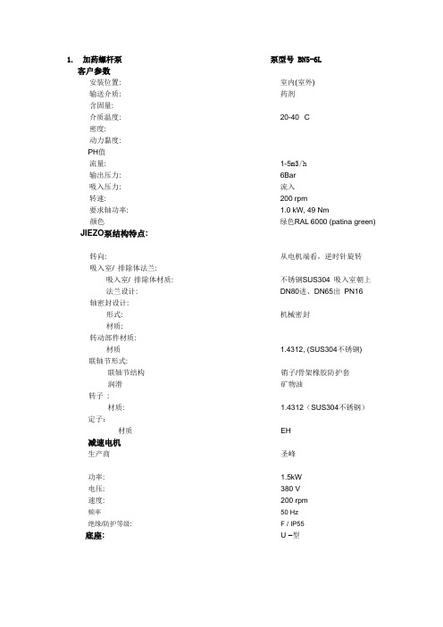
1. 加药螺杆泵泵型号 BN5-6L
客户参数
安装位置: 室内(室外)
输送介质: 药剂
含固量:
介质温度: 20-40 °C
密度:
动力黏度:
PH值
流量: 1-5m3/h
输出压力: 6Bar
吸入压力: 流入
转速: 200 rpm
要求轴功率: 1.0 kW, 49 Nm
颜色绿色RAL 6000 (patina green) JIEZO泵结构特点:
转向: 从电机端看,逆时针旋转
吸入室/ 排除体法兰:
吸入室/ 排除体材质: 不锈钢SUS304 吸入室朝上
法兰设计: DN80进、DN65出PN16 轴密封设计:
形式: 机械密封
材质:
转动部件材质:
材质 1.4312, (SUS304不锈钢) 联轴节形式:
联轴节结构销子/骨架橡胶防护套
润滑矿物油
转子:
材质: 1.4312(SUS304不锈钢)定子:
材质EH
减速电机
生产商圣峰
功率: 1.5kW
电压: 380 V
速度: 200 rpm
频率50 Hz
绝缘/防护等级: F / IP55
底座:U –型。
三螺杆泵产品样本(申贝泵业)
320
185
190
340
395
210
435
255
490
236
9
3GBW45,3G45 型 卧式泵外形及安装尺寸
三螺杆泵样本资料
外形安装尺寸(mm)
泵规格 机座号
AD
L
L1
L2
B
B1
B2
H
Y90L
155
345
430
680
Y100L 180
390
355
315
315
205
415
705
45x4-36 Y112M 190
410
Y132S
485
45x3-46
210
485
800
380
340
340
217
Y132M
525
45x2-52
Y160M
610
255
580
925
430
300
390
245
Y160L
655
10
3GFBW45,3GF45 型 法兰式泵外形及安装尺寸
三螺杆泵样本资料
泵规 机座
外形安装尺寸(mm)
格
号
AD L L1 L2 L3 L4 L5 L6 B B1 B2 H D1 D2 D3 D4 D5 D6
3、绷得吸入管路系统设计时应满足泵的吸入条件,即:
其中:H:泵吸入高度(m).
H=Hs-v²/2g-h
Hs:泵吸上真空高度(m).
v:泵的吸入口流速(m/s).
g:重力加速度(m/s²).
h:泵吸入管道中液力损失之和(m).
由上式可知,泵的吸入高度与泵的吸上真空高度、泵的入口流速和泵吸入端管路长短、弯
莫诺MONO泵
莫诺MONO泵莫诺泵公司(MONO)是世界上最早产生单螺杆泵的公司之一,在单螺杆泵的设计制造及应用方面,在世界上一趄处于单螺杆泵的领先地位。
莫诺泵公司具有完整的产品系列、各种不同的泵型,以适用于在广泛范围内的不同物料输送。
莫诺泵特性:1.输送范围广泛:从含气99%的物料到含固量60%的物料且粘度达1,000,000CPS的物料均可有效输送。
2.机械振动及噪声低,运行中物料没有脉动、剪切、湍流和搅拌。
3.自吸能力强,吸上真空高度可8.5米(28英尺),抗气蚀。
4.由钢性的转子与弹性的定子所组成的特殊结构使其具有能输送含固体颗粒的物料。
5.被输送物料的温度最高可达到摄氏205度(华氏400度)流量最高可达568立方米/小时。
压力最高达142公斤/每平方厘米。
6.流量与转速成线性关系,可以方便的通过调整转速来调整流量,达到控制流量的目的。
莫诺泵应用领域:石油工业、化学工业、市政工程、造纸工业、非金属工业、食品工业、其他工业等。
累进腔式泵累进腔式泵是处理各种泥浆、粘性介质、剪切敏感性介质、2或3相混合物以及需要超强自吸能力的理想的解决方案。
泵的设计原理非常适合大、小不同流量的处理应用。
莫诺泵机的主体部件是转子和定子。
当单螺旋转子在双螺旋定子中做离心旋转时,就形成一个连续的腔,并随着转子的旋转向泵机的排放端累进。
莫诺泵业生产各种泵机,产品型号达120多种,流量从10 l/h 至420,000 l/h不等。
压力可达48bar。
莫诺公司也可以提供压力达72的特殊用途泵。
根据这一设计原理,莫诺泵业还能制造多阶泵,以增加压力容量Monobloc B系列泵本系列泵的设计物有所值,紧凑的结构和最佳的性能曲线能满足广大客户的需要.产品具有卓越的自吸能力,吸升高度可达8米以上,正排量便于进行过程控制,同时,还可进行变速精确加药。
Monobloc B系列泵有33种规格,流量可达225m³/h,最大压力可达2bar。
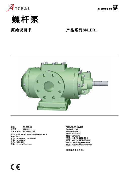
allweiler螺杆泵sn..er..原始说明书中文版
圈 . . . . . . . . . . . . . . . . . . . . . . . . . . . . . . . . . . . . . . . . . . 37 示图. 23 SN..ER..U2,内置式轴承,轴封填料 . . . . . . . 37 示图. 24 SN..ER..U4,内置式轴承,3个轴密封
目录
650.0002 ZHS – 550 411
BA-213.06
产品系列SN..ER..
5
本说明书
1 本说明书
本说明书 • 是泵的一部分 • 适用于所有提及的产品系列 • 描述在所有工作阶段安全正确的使用方法
置 . . . . . . . . . . . . . . . . . . . . . . . . . . . . . . . . . . . . . . . . . . 39 示图. 31 SN..ER..LB QW,外置式轴承,可添加润
滑油,冷却/加热轴密封圈,冷却(轴密封 圈) . . . . . . . . . . . . . . . . . . . . . . . . . . . . . . . . . . . . . . . . . 39 示图. 32 SN..ER..KA2,外置式轴承,不可添加润滑 油,轴封填料,推力轴承 . . . . . . . . . . . . . . . . . . . 40 示图. 33 SN..AR..D,外置式轴承,带压力端面密封, 无轴距,D14BS 适用于冷冻机油 . . . . . . . . . . 40 示图. 34 U8.23, SN..AR..U..BS,介质润滑的四点接触 球轴承,带压力端面密封,有轴距 . . . . . . . . . . 40 示图. 35 SN..ER..带有蒸汽加热盘/电热芯 . . . . . . . . . . 41
瑞典IMO三螺杆泵资料大全(超全)

瑞典IMO三螺杆泵资料大全(超全)产品介绍IMO AB三螺杆泵三螺杆泵系列LPD/ACD/ACEACG/ACF/LPQE4/D4/D6/GA三螺杆泵的奠基人公司介绍1923年卡尔·蒙特卢斯先生开发了全世界第一台三螺杆泵的数学模型并与企业家朋特-英格斯特姆先生建立合作关系。
1931年IMO AB成立,取两人名字的首字母作为公司的名称。
此后的多年内,IMO AB公司不仅自己生产三螺杆泵,还在全球范围内发放产品专利许可生产权,其中包括很多著名的制泵公司。
今天,IMO已成为三螺杆泵的代名词。
历经70余载,位于瑞典首都斯德哥尔摩的IMO 公司以其优良的产品质量,过硬的可靠性和便捷的服务在业界蠃得了良好的口碑,并有几十万台IMO的三螺杆泵服务于各行各业。
作为三螺杆泵的奠基人,尽管蒙特卢斯先生的设计理念距今已70多年,但是IMO公司产品的可靠性、耐用性和低噪声,在该应用领域仍然无出其右者。
IMO AB/ALLWEILER同属COLFAX PUMP GROUP(美国科尔法泵业集团)旗下,是当今全球技术最先进和最大的螺杆泵制造商。
IMO螺杆泵系列1、LPD系列螺杆泵产品概述流量:2~24升/分钟最大压差:10巴适用范围:润滑、循环、输送用途LPD泵可用于多种流体介质,如润滑油、燃油、植物油、液压油以及其它液压流体、乙二醇、聚合物、乳化液和任何带有一定润滑特性的非侵蚀性流体。
典型的应用有:大型机器如柴油机、齿轮等的润滑。
柴油机、分油机和焚烧炉的燃油供给和循环。
驳运和装卸润滑油、燃油和燃料油。
2、ACD系列螺杆泵产品概述流量:11~45升/分钟(50HZ)最大压差:7巴适用范围:润滑、循环、输送用途ACD泵可用于多种流体介质,如润滑油、燃油、植物油、液压油以及其它液压流体、乙二醇、聚合物、乳化液和任何带有一定润滑特性的非侵蚀性流体。
典型的应用有:柴油机、齿轮、燃气/蒸汽轮机、液压透平、造纸机等的润滑。
大型机械和液压系统的冷却和过滤,向变压器中泵运变压器绝缘油。
MOYNO选型技术表

莫依诺泵选型数据表(Selection Data Sheet) 单位: 日期:
姓名: 部门: 电话: 传真:
地址: 邮政编码:
电子邮件: 建议回复日期:
1. 使用环境: 数量:台
2. 流量: m3/hr.是否需要调节流量及拟采用调节方式;流量范围:
3. 输送的介质:
4. 介质特性: PH值: 磨蚀性: 粘度: cps 温度: ℃
固体含量: % 固体粒径: mm 比重
是否含气体及比例:
5. 进口压力: kg/cm2出口压力: kg/cm2
6. 密封要求: □填料密封□机械密封优先考虑用机械密封,必要的话填料也行
7. 电机要求:电压: V ph: 相Hz, 是否防爆: 防护等级:
8. 工作状态: □连续□不连续小时/天
9、如能用简单的图形描述工艺流程更有利于选型
注:红色字体为必填项目
传真、邮寄或E-mail给我们,我们将提供适合以上要求的泵型和价格供您选择。
VACUU·PURE 10NEW 干式螺杆泵真空泵说明书
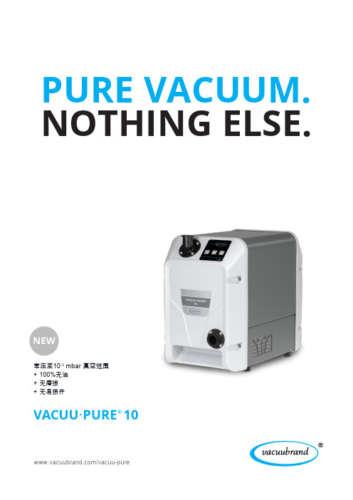
PURE VACUUM.NOTHING ELSE.VACUU ·PURE ®10/vacuu-pure常压至10-3 mbar 真空范围100%无油无磨损无易损件+++VACUU·PURE®创新.从常压至10-3mbar真空范围内,VACUU·PURE具备可靠无油真空技术的优势。
对用户而言,新型真空泵具备三个重要优点:100%无油,无磨损并且无易损件。
10-3 mbar.VACUU·PURE常压至在10-3 mbar 的压力范围内,具备可靠的无油真空技术的优点。
特殊设计的悬臂转轴和磁性齿轮,保证了完全无油的运行状态。
VACUU·PURE具有极好的冷凝液兼容性,即使处理大量蒸汽,也不需要气镇。
转轴无接触运行,零磨损。
无接触运行没有因为磨损造成的颗粒物技术可旋转的进气口垂直或水平方向都可以悬臂式转轴100% 无油气路再生模式大量的冷凝液也能快速干燥风冷式设计用途广泛Modbus RTU接口易于系统集成和远程控制.对真空需求低至10-3mbar,要求工艺过程清洁和产品纯净的应用,VACUU·PURE是一个理想的选择。
在一个高真空系统中,需要一个干燥且无碳氢化合物的真空环境,这对于许多应用来说是必不可少的。
作为涡轮分子泵的干式前级真空泵,VACUU·PURE提供了以前无油技术无法实现的高真空环境。
VACUU·PURE可以在较高的压力下连续运行,对较大的容积体系抽气至10-3 mbar,单泵即可实现,无需其他真空泵助。
无需更换易损件且省去了换油的麻烦, VACUU·PURE 可连续运行,无需定期维护。
VACUU·PURE可以在较高的压力下连续工作,因此在干燥箱中,可通过该单泵进行初始干燥和剩余干燥。
VACUU·PURE通过其优异的冷凝水兼容性,轻松处理大量蒸汽,无需气镇,因此可避免泵抽速降低及噪声增加等气镇带来的缺点。
IMO ACE三螺杆泵 文档

ACE025系列三螺杆泵ACE 025 N3 NVBP imo螺杆泵ACE 025 N3 NTBP imo螺杆泵ACE 025 N3 NQBP imo螺杆泵ACE 025 L3 NVBP imo螺杆泵ACE 025 L3 NTBP imo螺杆泵 ACE 025 L3 NQBP imo螺杆泵ACE 025 K3 NVBP imo螺杆泵ACE 025 K3 NTBP imo螺杆泵 ACE 025 K3 NQBP imo螺杆泵ACE032系列三螺杆泵ACE 032 N3 NVBP imo螺杆泵ACE 032 N3 NTBP imo螺杆泵ACE 032 N3 NQBP imo螺杆泵ACE 032 L3 NVBP imo螺杆泵ACE 032 L3 NTBP imo螺杆泵ACE 032 L3 NQBP imo螺杆泵ACE 032 K3 NVBP imo螺杆泵ACE 032 K3 NTBP imo螺杆泵ACE 032 K3 NQBP imo螺杆泵ACE038系列三螺杆泵ACE 038 N3 NVBP imo螺杆泵ACE 038 N3 NTBP imo螺杆泵ACE 038 N3 NQBP imo螺杆泵ACE 038 L3 NVBP imo螺杆泵ACE 038 L3 NTBP imo螺杆泵ACE 038 L3 NQBP imo螺杆泵ACE 038 K3 NVBP imo螺杆泵ACE 038 K3 NTBP imo螺杆泵ACE 038 K3 NQBP imo螺杆泵压差最大压差为16巴,但在低粘度介质中会有所降低,如下表所示:粘度,mm2/S(cst) 2 6 10 20最大压差(巴)812.415.216进口压力最大进口压力为7巴最小进口压力参见选用指南。
排量单位:立方分米/转尺寸 025L 025N 032L 032N 038K 038N排量 0.0098 0.0139 0.0206 0.0291 0.0388 0.0491泄压阀该泵配有一个带内部回路的泄压安全阀,防止出口管堵塞时引起泵进出口压差过大以保护泵。
2HE 2HM 2HR 2HE 2HM系列双吸双螺杆泵电子版选型样本

进口压力:-0.08~1.4MPa 介质温度:-20~120℃ 转速:750~1500r/min 工况及用途 采用特殊的不锈钢材质以适合于食品行业的特殊要求与介质相接触的各零件均符合食品卫生标准,可制 成小车移动式结构。
7、2HC 低压大流量双螺杆泵 性能范围 流量:500~2500m3/h 出口压力:0.1~1.6MPa 介质粘度:1~10000mm2/s
进口压力:0.05~0.5MPa 介质温度:-20~120℃ 转速:750~1500r/min 工况及用途 用作油品罐区,发送倒罐,装车装船泵,船舱底货油泵卸载泵适用于倒灌状态下大流量低压力场所各种 流体介质的输送。
10、LQ、LOS 螺杆泵专用过滤器 性能范围 口径范围:50~500mm 滤网目数:10、20、40、60、80 目/in 适用温度:-20~300℃
压力等级:1.6、2.5、4.0MPa 网口面积比:5、10、15、20 工况及用途 与螺杆泵配套的专用入口过滤器,LQ 普通型过滤器,LQS 为带双层保温夹套的过滤器。 11、螺杆泵专用变频自控系统 性能范围 功率:0.75~600kw 调频范围:5~60Hz 温度:-20~60℃ 工况及用途 与螺杆泵配套的专用变频自控系统,采用进口变频器可实现泵的软启动,泵的流量调节采用二次仪表, 可实现泵机组的超温保护和超压保护。
4、2VE、2VM 立式通用双螺杆泵 性能范围 流量:2~1200m3/h 出口压力:0.1~2.5MPa 介质粘度:0.5~100000mm2/s
进口压力:-0.08~0.8MPa 介质温度:-20~120℃ 转速:750~1500r/min 工况及用途 主要用于造船及安装空间狭窄的场所 2VE 适用于具有润滑性无固体杂质各种油品的输送,2VM 适用于不 含固体杂质的各种介质的输磅包括各种油品化学品及高分子物料的输送含气量小于 60%的洁净介质亦可 输送。
莫伊诺 500 系列400 系列磨盘泵 41502、42202、43302 和 44402 型号 维

Section:MOYNO® 500 PUMPSPage: 1 of 6Date:March 1, 1998SERVICE MANUALMOYNO® 500 PUMPS400 SERIES GRINDER PUMPS41502, 42202,43302, AND 44402 MODELSDESIGN FEATURESHousing: CastironPump Rotor: Chrome plated AISI 416stainless steelPump Stator:NBR (Nitrile)Shaft:AlSl 416 stainless steelBearings:Prelubricated, fully sealedball bearingsSeal:Mechanical(carbon/ceramic)Cutter Ring:Hardened steelCutter Disc:Cast ironCutter Tips:CarbideINSTALLATIONMounting Position. Pump may be mounted in any position. When mounting vertically, it is necessary to keep bearings above seals to prevent possible seal leakage into bearings.Pump is not self priming. Be sure pumping elements are located at or below water line.Piping. Piping to pump should be self-supporting to avoid excessive strain on pump housings; 4” NPT male connection on suction port, 1-1/4” NPT female connection on discharge port. Be sure suction lines are airtight. A non-clogging type check valve should be used in discharge piping to prevent flow back through pump. Use pipe “dope” or tape to facilitate disassembly and to provide seal.Drive. Any 56 frame, C-face, 1 HP, 1750 rpm, motor may be selected to meet code or application requirements. Motor is bolted directly to pump flange using hardware supplied with pump.CAUTION:Use only the rectangular key (202)supplied with hardware kit to preventdamage to shafts.Pump rotation must be clockwise when facing shaft to prevent rotor unscrewing from shaft. Check direction of rotation before startup.Maximum speed is 1750 rpm and is the recommended speed for most effective grinding. OPERATIONSelf-Priming. Pump is not self-priming. Pumping elements should be located at or below water line. Be sure suction lines are airtight.DO NOT RUN DRY. Unit depends on liquid pumped for lubrication. For proper lubrication, flow rate should be at least 10% of rated capacity.Pressure and Temperature Limits. Maximum discharge pressure is 80 feet of water or 35 psig. Unit is suitable for service at 10° to 160°F.Storage. Always drain pump for extended storageperiods.TROUBLE SHOOTINGWARNING:Before making adjustments,disconnect power source andthoroughly bleed pressure fromsystem. Failure to do so could resultin electric shock or serious bodilyharm.Failure To Pump.1.Motor shaft turns; pump shaft will not: Check key,collar, and collar screw. Adjust if necessary.2.Torn stator; possibly excessive pressure:Replace stator, check pressure at discharge port.3.Wrong rotation: Rotation must be clockwise whenfacing shaft.4.Threads in rotor or on shaft stripped: Replacepart. Check for proper rotation.5.Rotor pin sheared at rotor connection: Possiblyexcessive pressure. Replace parts, checkpressure at discharge port.6.Excessive suction lift or vacuum.Pump Overloads.1.Excessive discharge pressure: Check dischargepressure for maximum rating given in Table 1.Check for obstruction in discharge pipe.2.Fluid viscosity too high: Limit fluid viscosity to 100CP or 500 SSU.3.Insufficient motor HP: Check HP requirement. Will Not Start.1.Low voltage: Check power supply and wiring.2.Faulty motor: Replace or repair.3.Grinder section jammed: Rotate drive shaftcounterclockwise 1/4 turn to unjam cutters. Ifpump still will not start, check grinder section forjammed material and remove.Noisy Operation.1.Starved suction: Check fluid level, size of piping,and obstructions in pipe.2.Bearings worn: Replace parts.3.Insufficient mounting: Mount securely. Reducevibration induced noise by using a short sectionof hose on discharge piping.4.Cutter disc contacts stationary cutter ring: Referto grinder orientated problem section of guide. Seal Leakage.1.Leakage at startup: If leakage is slight, allowpump to run several hours to let faces run in.2.Persistent seal leakage: Faces may be crackedfrom freezing or thermal shock. Replace seal. Grinder Associated Problems.1.Grinder will not grind: Check for proper rotation.Check condition of cutter tips and cutter ring,replace as required. Cutter ring may be invertedto provide sharp cutting edge.2.Cutter disc interferes with stationary cutter ring:Check location of cutter ring, adjust as required.Check cutter tips for position, reposition asrequired.Check for bent shaft. Replace shaft, adjust cutter section and check pressure at discharge port.PUMP DISASSEMBLYWARNING:Before disassembling pump, disconnect power source andthoroughly bleed pressure fromsystem. Failure to do so couldresult in electric shock or seriousbodily harm.1.Disconnect power source.2.Disconnect suction and discharge piping.3.Remove screws (112C) holding reducer (9) tostator housing (14). Remove reducer and reducer gasket (83).4.Detach cutter tip (439) and cutter clamp (405)assemblies and cutter ring (196) from statorhousing (14) by removing cap screws (112D). Lift cutter ring out of stator housing.5.Cutter tip (439) can be detached from cutterclamp (405), and cutter disc (438) by removingscrew (112A).6.Remove cutter disc (438) by turning counter-clockwise (RH thread) with drive shaft (26) locked in position. A sharp rap against cutter tip (439)with a block of wood and hammer may berequired to loosen cutter disc from drive shaft(26).7.Remove screws (112C) holding stator housing(14) to pump body (1). Remove stator housing.8.Remove stator (21) by pulling off of rotor (22).9.Remove rotor (22) by removing pin (46) fromdrive shaft (26), twisting rotor may be required,with drive shaft locked in position. A suitablepunch may be required to remove pin from driveshaft.10.Carefully slide mechanical seal (69) off shaft (26).Carefully pry seal seat out of pump body (1). Ifany parts of mechanical seal are worn or broken, the complete seal assembly should be replaced.Seal components are matched parts and are notinterchangeable.11.Free collar (434) on shaft (26) by loosening setscrew (435).12.Detach motor from pump body (1) by removingscrews (112 B).13.The bearings (29) and shaft (26) assembly canbe removed from pump body (1) after snap ring(66) has been removed. To remove theassembly, lightly tap the shaft at threaded endusing a block of wood to protect the threads. The bearings may be pressed off the shaft.Note:When replacing bearings, always press on the inner race when assembling to shaft, and onthe outer race when pressing bearings into thehousings.14.Adaptor plate (40) and adaptor plate gasket (79)can be removed from pump body by removingscrews (112C).Page 2Page 3 Parts ListPump Model NumbersItem No.Description†4150242202†4330244402 1Pump Body350-0629-0009Reducer330-4196-00014Stator Housing350-0618-000*21Stator340-3501-120340-3502-120340-3503-120340-3504-120 *22Rotor330-4605-000330-4604-000330-4603-000330-4602-000 26Drive Shaft340-2371-00029Bearing (2 req.)630-0502-06140Adaptor Plate330-4201-00046Rotor Pin320-4486-003320-4486-004 66Snap Ring320-2794-000*69Mechanical Seal320-6500-00077Slinger Ring320-6385-00079Adaptor Plate Gasket320-5888-000*83Reducer Gasket320-5878-000112A Screw, SS Cap (8 req.)320-4787-006 (8-32 x 3/8)112B Screw, Hex Hd (4 req.)619-1530-161 (3/8-16 x 1)112C Screw, SS Hex Hd (18 req.)320-5615-014 (1/4-20 x 1)112D Screw, SS Cap (4 req.)320-5395-016 (1/4-20 x 1-1/2)196Cutter Ring330-4200-000202Key320-6292-000 (3/16 x 1/4 x 3/4)215A Lock Washer, SS (4 req.)623-0010-411 (3/8)215B Lock Washer, SS (18 req.)320-5616-039 (1/4)405Cutter Clamp (4 req.)320-5887-000434Coupling320-5811-000435Set Screw606-0060-053438Cutter Disc330-4199-000*439Cutter Tip (8 req.)320-5876-000* Recommended spare parts† Not available as standard model; must be obtained by retrofitting with Repair/Conversion Kit listed below;REPAIR/CONVERSION KIT NUMBERSDescription Model 41502Model 43302ItemNo.–Kit No.311-9127-000311-9128-00022• Rotor330-4605-000330-4603-00021• Stator340-3501-120340-3503-12046• Pin320-4486-003320-4486-003Page 4Mounting Hardware Kit When ordering parts, please specifypump model number, pump serial number,part number, part description and quantity.PUMP ASSEMBLY1.Secure adaptor plate gasket (79) and adaptorplate (40) to pump body (1) using lock washers(215B) and screws (112C).2.Press bearings (29) on shaft (26), and locateslinger ring (77) near bearing on threaded end of shaft.3.Press shaft assembly into pump body (1)securing with snap ring (66).4.Install mechanical seal (69) using the followingprocedure:a.Clean and oil sealing faces using clean lightoil (not grease).b.Oil the outer surface of the seal seat, andpush the assembly into the bore in the pumpbody (1), seating it firmly and squarely.c.After cleaning and oiling the shaft, slide theseal body along the shaft until it meets theseal seat.d.Install seal spring and spring retainer on shaft.5.Locate pinhole on threaded end of shaft (26) andinstall rotor (22) on shaft. Align slot on rotor withpin hole and install pin (46).6.Secure stator (21) and stator housing (14) topump body using lock washers (215B) andscrews (112C).CAUTION: Be sure to use a thread lockingcompound on threads of screws (112and 112C).7.Attach cutter tips (439) to cutter disc (438) withscrews (112A). See Figure 1 for correct position.8.Screw cutter tip and cutter disc assembly ondrive shaft (26) in a clockwise direction (RHthread).9.Attach cutter tip (439) to cutter clamp (405) usingscrew (112A). See Figure 2 for correct position.CAUTION: Be sure to use a thread lockingcompound on threads of screws(112A).10.Install cutter ring (196) and cutter tip/cutter clampassemblies using the following procedure:a.Place cutter ring (196) in stator housing (14).b.Position cutter tip/cutter clamp assemblies oncutter ring, screwing screw (112D) finger tight.Cutter tip/cutter clamp assemblies shouldpoint to center of shaft.c.Position cutter ring (196) to provide clearancearound cutter disc (438), and tighten screws(112D). Check interference between cutterdisc and cutter ring by rotating shaft severalrevolutions. Readjust cutter ring if necessary.11.Secure reducer gasket (83) and reducer (9) tostator housing (14) using lock washers (215B)and screws (112C). The cast tabs on the reducer(9) should be located in the spaces between thecutter tip/cutter clamp assemblies.12.Slide coupling (434) with set screw (435) overshaft (26).13.Secure motor (70) to pump body (1) using lockwashers (215A) and screws (112B).14.Align keyways in motor and pump shafts, andinsert key (202).CAUTION: Use only the rectangular key (202)supplied with hardware kit to preventdamage to shafts.15.Secure key (202) by tightening set screw (435) incoupling (434) against the key.16.Proceed as in installation instructions.Page 5© 1999 by Moyno, Inc.® Moyno is a registered trademark of Moyno, Inc.Printed in U.S.A.。
莫伊诺(Moyno)破碎机产品说明书
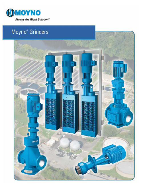
The Moyno line of grinders meets the broad needs of any industry requiring solids reduction or waste conditioning.The diverse line of grinders ensures that Moyno has the right equipment to meet your challenge.Moyno® Annihilator™The Moyno Annihilator utilizes the field-proven counter-rotating,hex-agonal shaft design with intermeshing cutters and spacers.The Annihilator vastly increases the cutting capabilities of other commonly available twin shaft grinders by utilizing cutting teeth on the spacers,thereby improving the cutting efficiency while decreasing the particle size processed through the unit.This patented design also eliminates the greatest cause of failure of conven-tional units — that of stringy material wrapping around the spacers,causingseal failure,mechanical seizure and ultimately,shaft fracturing.The drive components and the cutter cartridge can be removed from the flange housing of the Series 4 design as one assembly.Replacement cutter cartridge assemblies are available for quick replacement and minimal downtime.The Moyno Annihilator also retrofits other twin shaft grinder units.It has the same dimensions and same piping configurations but with far superior performance. Features and Benefits •Protects downstream equipment from being plugged or damaged from large solids,thus reducing expensive repairs and down time •Slow rotating cutters work best onlarge and dense solids•Improved cutting efficiency withover double the cutting edges•High flow side rails on Series 3 C3Aprovide an increase in flowthrough for greater efficiency•Mechanical seal mounted on aseparate stainless steel sleevefor easy and quick replacement•Seal cartridge offers reliableoperation with less downtime•Cutter cartridge consists of oneassembly for quick replacement•One-piece flange housing onSeries 4 ensures quick and easyrepair with no flange bolts todisconnect•Various drive,housing,cutter,spacer/cutter and shaft optionsfor application versatilityMoyno® Max-FlowAnnihilator™GrinderSystemInstalling and maintaining equipmentto protect the downstream pumps,valves and process equipment inwastewater treatment plants andits lift stations can be expensiveand environmentally challenging.Bar rakes and screens and drumscreen grinders all have their costand performance disadvantages.The Moyno® Max-Flow Annihilator™Grinder System is a custom engi-neered headworks debris handlingsystem that protects downstreampumps,valves and process equipmentin wastewater treatment plants andtheir lift stations.The cost-effective,low maintenance Moyno Max-FlowMoyno®Sets the Standard in Grinding EquipmentAnnihilator Grinder System can be used in place of bar rakes and screens as well as drum screen grinders for enhanced performance.The Max-Flow system contains two or more Annihilator grinders mounted side-by-side in a stainless steel retrieval frame in the headworks of a waste treatment system.They can be installed in an in-line or a staggered or offset design to accommodate a variety of channel widths.The frame is engineered-to-order and pre-fabricated.It includes guide rails to permit the independent retrieval of each grinder for easy maintenance. Steel panels can also be inserted in place of a grinder to divert the flow to the remaining grinders during maintenance,eliminating the need forcostly diversion or by-pass channels.Stainless steel or FRP control panelscan be installed to control the oper-ation of each grinder independentlyusing manual or automated controlsystems.Features and Benefits•Fewer maintenance issues than barrakes,bar screens,and drum screens•Lower maintenance costs•Lower initial costs than competingtechnologies•Lower energy usage since allgrinders in the system don’t needto operate continuously•Better performance in reducingthe particle size of debris floatingthrough the waste treatment system•Better environmental choice sinceall processing of debris is doneunderground in the lift stationMoyno® Edge™Grinder CartridgeWhen the grinder cartridge failsin your in-line or uni-body MuffinMonster® grinder,you now have analternative.Instead of purchasing anew or refurbished replacementgrinder cartridge from JWC Environ-mental®,you can purchase a newone from Moyno.The Moyno Edge grinder cartridgeshave been specifically designed tofit within the Muffin Monster®grinder housing,allowing you toretain and use your existing gearreducer,motor,and control panel.Moyno stocks the Moyno Edgegrinder cartridges at most of its NorthAmerican regional distributors,andcan ship it quickly to minimize yourdowntime.The Edge includes a patent pendingshrouded,dry running,hard faceseal;and bolt-on shaft collarsinstead of snap rings.You will notfind all of these design advantageson competing products.Moynobacks its products with a full oneyear warranty against defects inmaterials and workmanship.While the performance of yourequipment is critical and the qualityof your customer experience isimportant,the cost of replacementparts is also a consideration.TheEdge is priced lower than the originalequipment replacement cartridges.Features and Benefits•Easy installation with no specialequipment,tools,adapters,modifi-cations,training,or proceduresrequired•Fast delivery for minimal downtime•Longer product life resulting fromMoyno’s high quality,careful atten-tion to product design,materialselection,manufacturing work-manship,and product testing•Responsive customer support withan extensive distributor network oftrained customer service personneland experienced service technicians•Cost savings due to lower pricinglevels© 2012 by Moyno,Inc.®Moyno is a registered trademark of Moyno,Inc.Bulletin 135-D ™ Annihilator,Max-Flow and Edge are trademarks of Moyno,Inc.Printed in U.S.A.®Muffin Monster is a registered trademark of JWC Environmental.Moyno is not a distributor or manufacturer for JWC Environmental.212Moyno,Inc.is a Unit of Robbins & Myers,Inc.U.S.A.877.4UMOYNO Outside U.S.A 937.327.3553Moyno® PipelinerThe Moyno Pipeliner provides effective solutions to the time consuming and costly problems of ragging and inconsistent particle size frequently associated with handling solids in wastewater treatment processes.Features and Benefits•The Pipeliner design consists of a single shaft rotating a headstock •The headstock contains tungsten carbide-tipped cutting edges running against a hardened tool steel shearplate•Headstock,shearplate and body casting designs minimize jamming and eliminate the need for expen-sive anti-jamming devices •Single mechanical seal with silicon carbide faces•Simple,efficient design needs minimal maintenance•Exclusive Quick-Change Cartridge Assembly is simple to separate from the PipelinerMoyno® 500 Grinder PumpMoyno 500 Grinder Pump offers constant,uniform,non-pulsating flow that provides low shearing action for minimum degradation of shear-sensitive materials and low velocity capabilities for effective pumping of viscous fluids.Features and Benefits•Compact,lightweight utility pump •Eliminates excessive operating noise •Flow rates to 15 GPM •Discharge to 100 PSI •Cast iron cutter disk•Replaceable carbide cutting tips anda hardened tool-steel cutter ring。
单螺杆泵样本

单螺杆泵样本
单螺杆泵,G型螺杆泵,偏心螺杆泵一、G型单螺杆泵产品概述单螺杆泵因定子选用多种弹性材料制成,所以这种螺杆泵对高粘度达到80%流体的输送和含有硬质悬浮颗粒介质或含有纤维介质的输送,有一般泵种所不能胜任的特性。
其流量与转速成正比,G型螺杆泵广泛应用于食品冶金、造纸、印染、化工、化肥制药等工业部门使用.传动可采用联轴器直接传动,或采用高速电机,三角带,变速箱等装置变速。
二、G型单螺杆泵产品特点G型单螺杆泵具有自吸能力强、吸入高度强;螺杆泵零件少,结构紧凑,体积小,维修简单,转子和定子是单螺杆泵的易损件,结构简单,便于装拆。
是按迥转啮合容积式原理工作的新型泵种。
G型单螺杆泵主要工作部件是偏心螺杆(转子)和固定的衬套(定子)。
采用无毒无味的食用橡胶,工作温度可达120摄氏度,如果采用高温120摄氏度—350摄氏度时可同本单位联系。
由于该二部件的特殊几何开头分别形成单独的密封容腔。
介质由轴向均匀推行流动。
内部流速代低,容积保持不变。
压力稳定,因而不会产品涡流和搅动。
每级泵的输出压力为0.6MPa—1.2MPa,扬程60m—120m(清水),自吸高度一般在3m以上.可以当自吸排污泵产品使用。
三、G型单螺杆泵的优点1、与离心泵相比单螺杆泵无需安装阀门,流量是稳定的线性流动;2、与气动隔膜泵相比单螺杆泵可输送各种混合杂质含有气体及固体颗粒或纤维的介质,也可输送各种腐蚀性物质;3、与齿轮泵相比,单螺杆泵可输送高粘度的物质;4、与柱塞泵,隔膜泵及齿轮泵不同的是,螺杆泵可用于药剂填充和计量。
单螺杆泵型号及参数

【G 型单螺杆泵】工作原理与特性:
G 型单螺杆泵是按迥转啮合容积式原理工作的新型泵种。主要工作部件是偏心螺杆(转子)和固定的衬套(定子)。由于该部件的特殊几何开头分 别形成单独的密封容腔。介质由轴向均匀推行流动。内部流速代低,容积保持 不变。压力稳定,因而不会产品涡流和搅动。 单螺杆泵被广泛用于 各行业输送各类介质,恒压连续运行,无脉动,介质输送无破损,通过调节转速改变流量从而达到计量的目的。本产品适合输送具有以下特性的 介质:固体含量高(最大粒径可达150mm)或无固体含量|各种粘度(1mPas-3百万 mPas)的介质|触变性和易膨胀性介质|剪切敏感性介质|磨蚀性介质 |有/无自润滑性的介质|腐蚀性介质(pH=O-14)|粘结性介质|有毒性介质|流量大、压力高·流量范围从每小时几毫升到500m3(2200gpm)·压力范围 最高可达48bar,特殊设计可达72bar。同一种传动部件可与四种不同设计的转子/定子匹配,为您提供最佳使用方案。
【G 型单螺杆泵】结构图:
1
出料口
4
螺杆轴
7
连节轴
10 轴承座 13 连轴器 16
传动轴பைடு நூலகம்
2
拉杆
5 万向节总成 8
填料座
11 轴承盖 14
轴套
17
底座
3
定子
6
吸入口
9
填料压盖
12 电动机 15
轴承
【G 型单螺杆泵】主要用途:
1、环境保护:工业污水、生活污水、含有固体颗粒及短纤维的污泥浊水的输送。特别适用于油水分离器,板框压滤机等设备。 2、船舶工业:轮底清洗、油水、油渣、油污水等介质的输送。 3、石油工业:输送原油。近年来,尤其成功地抽吸地下千米之深的原油与水的混合物,煤田里的煤田气和水的混合物,从而大大降低了 机械采油、采煤田气的成本。当油田到了后期,使用螺杆泵往地层内灌注聚合物增加油田采收率。 4、医药、日化:各种粘调浆、乳化液、各种软膏化装品等的输送。 5、食品罐头业:各种粘稠淀粉、食油、蜂密、糖酱、果浆、奶油、鱼糜肉糜以及其下脚料的输送。 6、酿造业:各种发酵粘稠液、浓酒槽、粮食制品渣各种酱类、浆和含有块关固态物的粘液等。 7、建筑工业:水泥沙浆、石灰浆、涂料及其经糊状体的喷涂与输送。 8、采矿工业:矿井内的含固体颗粒的地下和污浆水等排送到地面。 9、化学工业:各种悬浮液、油脂、各种胶体浆、各种粘合剂。 10、印刷、造纸工业:高粘度油墨、墙纸的 PVC 高分子塑料糊和各种浓度的纸浆,短纤维浆料的输送。
莫伊诺L8型号单螺杆泵维修手册说明书

Section:L and J FRAME PUMPSPage: 1Date: (Revision 9/94) OPERATION – ASSEMBLY INSTRUCTIONS AND PARTS LIST FOR“L8” DRIVE END(FRAME SIZES 1L8, 2L8, 3L8, 3M6, 3P4, 6P4, 9P4)GENERALThe Moyno® Pump is one of the most versatile pumps available, It has been proven in thousands of applications over the past 40 years. It is backed by the experience gained over the years, both in application and manufacturing know-how.The Moyno progressing cavity pump is a single-screw rotary pump. The pumping action is created by the single helical rotor rolling eccentrically in the double threaded helix of the stator. In its revolution, the rotor forms in conjunction with the stator a series of sealed cavities 180 degrees apart. As the rotor turns, the cavities progress from the suction to the discharge. As one cavity diminishes, the opposing cavity is increasing at exactly the same rate. Thus, the sum of the two discharges is a constant volume. The result is a pulsation-less positive displacement flow with no valves.NAMEPLATE DATAThe Moyno Pump nameplate, located on the bearing housing, carries the serial number, frame size, and type designation. All are extremely important and must be used when ordering spare parts.Record the nameplate data of your pump in the spaces provided in the heading of Page 3.Moyno Pumps are identified by Frame and Type. Pump Frame is essentially an indication of size. It consists of a number, a letter, and a number (i.e. 2L8). The first number indicates the number of stages in the pumping elements. The letter indicates the model. The final number indicates the size of the rotor-stator pumping elements. A frame 2L8 pump, therefore, has two stages of size 8 pumping elements.The “L” in the frame size indicates a standard relationship between the housing, bearings, and drive shaft and the size of the pumping elements. Many variations may be made by adapting smaller element sizes to a larger drive end size. This may be necessary due to the severity of a specific pumping application. In cases where the drive end (housing, bearings, and drive shaft) is one size larger than the element size normally used, the pump is referred to as an “M” frame pump (i.e. 3M6). If the drive end is two sizes larger than the element size, the pump is referred to as a “P” frame. Thus, a frame 3L8, 3M6and 3P4 would all use a common drive end.Type designation is a series of letters which identify the “Materials of Construction” in component groups of parts. The usual type designation will consist of three letters.The first letter identifies the material of the suction housing casting or the body casting where the bearing housing is a part of the suction housing.The second letter indicates the material used in the drive shaft, pins, connecting rod, rotor, and other minor metallic parts in contact with the material being pumped.The third letter determines the material of the stator. It identifies only the stator material and not that of the tube in which the stator is placed.A typical type designation such as CDQ would result in the following:C = Cast Iron Suction HousingD = Hardened Steel Internals including driveshaft, pins, connecting rod, rotor, andother minor metallic parts in contact withthe material being pumpedQ = Nitrile Synthetic Rubber Stator (70 durometer)The following letters identify the actual materials that are used in standard construction:B - EPDM Q - Nitrile (70 durometer)C - Cast Iron R - Natural Rubber (55durometer)D - Hardened Steel S - Stainless Steel, type#316F - Fluoroelastomer T - Teflon (glass impreg-nated)G - Stainless Steel,#416Also included on the nameplate is the three-character trim code designation. This only appears on pumps which have semi-standard or special construction. The first letter identifies sealing variations, the second character indentifies internal variations, and the third letter identifies rotor variations.On page 5 of this manual are variations available for modifying pumps to meet specialized pumping conditions. If the trim code of your pump is other than “AAA”, contact• your nearest Moyno representative for clarification. Do not use any variation unless you have determined that it is compatible with your application.* ADD THIRD LETTER OF TYPE DESIGNATION TO COMPLETE PART NUMBEREX: TYPE CDQ PUMP – ADD Q TO BASIC NUMBER OF STATOR** Bearing Kit includes Items A thru G *** Connecting Rod Kit includes items Q thru U + see pages 5 - 6 for variations“L8” DRIVE END PARTS TYPE DESIGNATIONSSelect type column corresponding to type designation at left.Order by part number Refer to frame size to select proper rotor and stator.REF. NO.DESCRIPTIONCDQ CDR CDB CDF Part No. CDD CDG CDT Part No. CSQ CSR CSB CSF Part No. CSD CSG CST Part No. SSQ SSR SSB SSF Part No. SSG SST Part No.A. Ball Bearing (Radial) A08291 A08291 A08291 A08291 A08291 A08291B. Ball Bearing (Thrust) A08301 A08301 A08301 A08301 A08301 A08301C. Bearing Spacer A08331 A08331 A08331 A08331 A08331 A08331D. Bearing Lock Nut A08581 A08581 A08581 A08581 A08581 A08581E. Bearing Lock Washer A08591 A08591 A08591 A08591 A08591 A08591F. Grease Seal (Radial) A08611 A08611 A08611 A08611 A08611 A08611G. Grease Seal (Thrust) A08621 A08621 A08621 A08621 A08621 A08621 Bearing Kit** K08291 K08291 K08291 K08291 K08291 K08291H. Bearing Housing A08051 A08051 A08051 A08051 A08051 A08051I. Bearing Cover Plate A08341 A08341 A08341 A08341 A08341 A08341J. Pump Support A08371 A08371 A08371 A08371 A08371 A08371K. Shaft Collar A08491 A08491 A08491 A08491 A08491 A08491 M. Lantern RingA08571 A08571 A08571 A08571 A08571 A08571N. Stator Support 1 L8, 2L8, 3L8 A08381 A08381 A08381 A08381 A08381A08381 3M6, 3P4, 6P4, 9P4 A08382 A08382 A08382 A08382 A08382A08382 O. Support Bushing 3P4 A08711 A06712 A08711 A06712 A08711 A067129P4 A06712 ---------- A06712 ---------- A06712---------- P. Pin Retainer A08501 A08501 A08501 A08501 A08501 A08501 Q. Retaining Screw Washer A08731 A08731 A08731 A08731 A08731 A08731 R. Connecting Rod Washer A08531 A08531 A08531 A08531 A08531 A08531S. Connecting RodB0825D B0825D B0825S B0825S B0825SB0825S T. Rotor Pin or Shaft Pin B0845D B0845D B0845S B0845S B0845SB0845S U. Drive Pin Retaining Screw B0854D B0854D B0854S B0854S B0854S B0854S Connecting Rod Kit*** K0825D K0825D K0825S K0825S K0825S K0825S V. Suction Housing B08021 B08021 B08021 B08021 B08026 B08026W. Reducer1L8, 2L8, 3L8 only B08091 B08091 B08091 B08091 B08096B08096 3M6 B06091 B06091 B06091 B06091 B06096B06096 3P4 B04091 B04092 B04091 B04092 B04096B04097 6P4 B06091 B06091 B06091 B06091 B06096B06096 9P4B08092 ---------- ---------- ---------- B08097---------- X. Drive Shaft + B08261 B08261 B08266 B08266 B08266B08266 Y. Packing Gland B0841D B0841D B0841S B0841S B0841SB0841S Z. Packing + B08421 B08421 B08425 B08425 B08425 B08425AA. Packing WasherB0865D B0865D B0865S B0865S B0865SB0865S BB. Adapter Bushing3M6, 6P4 B08511 B08511 B08511 B08511 B08516 B08516 3P4 Only B08512 B08513 B08512 B08513 B08517 B08518 9P4 Only B08513 ---------- B08513 ---------- B08518 ---------- EE. Stator Frame 1L8C4108* C4108* C4108* C4108* C5108* C5108*Frame 2L8 C4208* C4208* C4208* C4208* C5208*C5208* Frame 3M6 C4306* C4306* C4306* C4306* C5306*C5306* Frame 3P4 C4304* C4304* C4304* C4304* C5304*C5304* Frame 6P4 C4604* C4604* C4604* C4604* C5604*C5604* Frame 9P4 C4904* ---------- C4904* ---------- C5904*---------- FF. Rotors Frame1L8 + C71081 C71081 C81081 C81081 C81081C81081 Frame 2L8 + C72081 C72081 C82081 C82081 C82081C82081 Frame 3L8 + C73081 C73081 C83081 C83081 C83081C83081 Frame 3M6 + M73061 M73061 M83061 M83061 M83061M83061 Frame 3P4 + P73041 P73041 P83041 P83041 P83041P83041 Frame 6P4 + P76041 P76041 P86041 P86041 P86041P86041 Frame 9P4 + P79041 ---------- P89041 ---------- P89041---------- 3INSTRUCTIONS FOR DISASSEMBLY AND ASSEMBLY Frames 1L8, 2L8, 3L8, 3M6, 3P4, 6P4, 9P4Disassembly Procedure1. Disconnect the power source.2. Close the suction and discharge valves to isolate thepump from the line.3. Turn off flush water to packing or rotary seal if used.4. Remove drain plug in suction housing to drain awayany fluid remaining in pump.5. Place a support block under suction housing in area ofdrain plug. Wooden blocks are sufficient. The purposeis to prevent undue stress on pump support when pumpis disassembled.6. Disconnect piping from stator end of pump.7. Stator Removal - With pipe wrench or strap wrenchremove discharge reducer (W). Remove cap of statorsupport and with strap wrench or pipe wrench, unscrewthe stator (EE) from the suction housing. Pull Stator offthe rotor.8. Rotor Removal - The rotor (FF) is removed with theconnecting rod (S) and rotor pin (T) as a unit. Removalof the unit is accomplished by removing the two drivepin retaining screws (U) located in the shaft collar (K).This step reveals the shaft drive pin (T), which is removed by driving the pin from the drive shaft (X) witha small punch or drift pin. Slide the shaft collar towardthe packing gland (Y) and remove the retaining screwwashers (Q) from each side of the drive shaft. The rotorand connecting rod can now be removed by pulling them from the pump. To disassemble, clamp the connecting rod (S) by its mid-section in a vise and, witha drift pin, drive the pin retainer (P) from the head of therotor. The rotor pin (T) can now be removed from therotor freeing the connecting rod. Remove the connecting rod washers (R) if present.9. To remove packing (Z), remove nuts holding packinggland (Y). Slip packing gland from studs, remove packing rings, lantern ring (M), and remaining packingrings. Packing rings can be removed with a standardpacking puller. Note: If step 10 is to be performed, itshould precede step 9 as packing can then be removedby freeing packing gland and driving packing, lanternring, and packing washer (AA) from housing using a small rod. Rod should enter where stator screws intosuction housing. Place rod on packing washer and tap.Entire set should easily exit from opposite end of stuffing box.10. Drive Shaft & Bearing Removal - With rotor removedit is now possible to remove the drive shaft and bearings as a sub-assembly. Remove the four cap screws holding the bearing cover plate (I) and slip fromshaft. Insert a bar or rod into the hollow end of driveshaft (X) where it enters the suction cavity. By tappingon the rod the entire assembly will be forced from thebearing housing.To disassemble, remove bearing lock nut (D) andbearing lock washer (E). Using an arbor press removeradial bearing (A), bearing spacer (C), and thrustbearing (B). Apply pressure to inner race only. Whenreplacing drive shaft and/or bearings, it is recommended that both grease seals be replaced.Grease seals are pressed into the bearing housing andbearing cover plate.Assembly ProcedureMoyno pumps are reassembled in the reverse order of disassembly with special notes as outlined below:1. Always replace all old washers, “0” rings and packing.We also recommend replacing grease seals when new bearings are installed.2. Bearing Shaft Assembly - When installing newbearings, make sure that they are seated against the shoulder on the shaft. Replace bearing lock washer and bearing lock nut. Tighten bearing lock nut securely. Bend tab down onto lock nut to prevent loosening of nut.Make sure that the shaft collar, packing gland, and packing washer are installed on the drive shaft as the hollow end emerges in the bearing housing and approaches the stuffing box area.When replacing the bearing cover plate, tighten all cap screws evenly to prevent damage to the bearing cover plate and thrust grease seal.Do not over-lubricate bearings. (See Maintenance)3. When installing the connecting rod, make sure that thehole in the rod is aligned with the holes in the drive shaft and shaft collar before inserting the pin. Always use retaining screw washers and make sure that the hollowed end of the retaining screw fits over the end of the shaft pin to ensure a tight fit. Retaining screws must seat on retaining screw washers and not on pin.4. When replacing packing, insert three rings on the shaft,the lantern ring, and then four more rings. This will allow the lantern ring to line up with the grease fitting on the stuffing box. Make sure you stagger the ends of the packing rings.When installing the new packing, you may find that all but one ring will go on the drive shaft. When the pump has run for a short time and the new packing is compressed, this final ring can be installed.5. When installing the stator on the rotor, it is best tolubricate the rotor with water (or a lubricant compatible with the rubber in the stator) to allow the stator to slip on easier. (Grease or oil is not compatible with type “R” or “B” stators.)When replacing the stator, always tighten it with the pipe wrench on the end of the stator nearest the suction housing. This will prevent it from binding and damaging the threads.If your stator has a stainless steel sleeve, use a teflon tape or similar material on the threads before replacing -- on all stators with a carbon steel sleeve, use pipe dope.46. Caution: Dry operation is harmful to the pump.Always fill the pump with fluid to be handled prior to start up. Check any valves in discharge line to determine that no restrictions exist.MAINTENANCEThe Moyno pump has been designed for a minimum of maintenance, the extent of which is routine lubrication and adjustment of packing and infrequent lubrication of the bearings. The pump is one of the easiest to work on in that the main elements are very accessible and require few tools to disassemble.PackingThe Moyno pump is normally furnished with die formed packing. The packing may be either grease lubricated through a grease fitting in the stuffing box or have plumbing connected to the housing to allow a water flush. (See Water Flush of Packing)Packing gland adjusting nuts should be evenly adjusted so they are little more than finger tight. Over-tightening of the packing gland may result in premature packing failure and possible damage to the shaft and gland. When the packing is new, frequent minor adjustments are recommended for the first few hours of operation in order to compress and seat the packing. Greasing the packing often but with limited quantities of grease is the best practice. This can be done through a grease fitting which leads to a lantern ring in the mid-section of the packing. Do not use a one-piece spiral wrap of packing.Water Flush of PackingWhen the material being pumped is abrasive in nature, it may be advantageous to flush the packing to prevent leakage under packing and excessive shaft wear.Clean water can be injected through a 1/8” NPT tapped hole that normally houses the grease fitting for lubricating the packing. The water can be permitted to leak axially along the shaft in either direction or canbe removed from the second tapped hole in the stuffing box. In both cases, the discharge from the stuffing box should be throttled slightly to maintain 10-15 PSI higher pressure in the stuffing box than is present in the suction housing. This is a basic arrangement, other variations can be used.(1) Throttling Valve (2) Pressure Guage (3) Pressure Regulating ValveThis is a basic arrangement, other variations can be used. (1) Throttling Valve (2) Pressure Guage (3) Pressure Regulating ValveBearingsThe Moyno pump is equipped with ball bearings inthe drive end size L2 through L10. The bearings are lubricated at the factory and do not need additional lubrication for at least 1500 hours of normal operation.When relubricating the bearings, the bearing-shaft assembly should be removed (See Disassembly in-structions) and cleaned of old grease. Add only enough grease to fill the area between the bearings1/3 full. Add a few drops of oil to bearing seals before reassembling. It is normal for bearings to run warm tothe touch for the first few hours of operation.Any type of Ep Lithium soap base grease is satisfactory for bearing lubrication. The use of Sodiumor Calcium base grease is not recommended.The following is a partial listing of approvedbearing lubricants:Dow Corning DC 33Keystone Lubricating Co. Keystone #89Texaco RegalAFB2Shell Oil Co. Cyprina #3Humble Oil & Refining Co. Beacon 325American Oil Co. Supermil Grease #A72832Mobil EP1Shell Oil Co. Alvania #2VARIATIONS OF STANDARD PARTSROTORS identified on parts listing are standard size with hard-chrome plated surface. Other variationsof rotor size and finish may be ordered by selectingthe standard rotor part number and changing the last digit of the rotor number as follows:2 = Standard size, non-plated3 = Undersize, chrome-plated4 = Undersize, non-plated5 = Oversize, chrome-platedDo not change rotor sizes without consulting yourlocal Moyno Sales Office. These variations are usedfor certain specialized pumping conditions only.5PACKING VARIATIONS listed are common to most type designations. Others may be specified by changing the last digit to the following: 1 = Standard on all type CDQ pumps3 = Standard on all type CDR & SSR pumps 5 = Standard on all type SSQ pumps 7 = Optional--Solid Braided Teflon8 = Optional--Teflon impregnated white asbestosDRIVE SHAFTS shown have hard-chrome plating on the packing wear area. If non-plated drive shafts are required, select the standard part number and change the last digit to next higher number.Example: B08261 to B08262.L8 STANDARD HARDWAREITEM SIZE # REQ. Bearing Cover Plate Screw1L X 1/2 D-13 4 Lock Washer 4 Suction Housing Bolt 3 1/4L X 1/2 D-13 4 Lock Washer 4 Stator & Pump Support Screw2L X 5/8 D-11 4 Packing Gland Stud 4 L 1/2 D-13 2Nut 1/2 D-13 2 Suction Housing Drain Plug 1/2 D 3 Drain Plug on Stuffing Box1/8 D 1 Grease Fitting on Stuffing Box1/8 D 1 Pipe Plug on Bearing Housing 1/8 D 2 Hex Key 9/16 1RECOMMENDED SPARE PARTSThe Moyno pump has been designed and built with all wearable parts replaceable. A recommended inventory of spare parts isdependent upon the application and importance of continued operation.For the shortest possible downtime, we recommend the following parts be stocked:1 - Rotor 1 - Stator1 - Connecting Rod KitThe above is only a suggested list. For further assistance in determining what you’ll need for your application, contact your Moyno representative.6© 1988 by Moyno, Inc.® Moyno is a registered trademark of Moyno, Inc. Moyno, Inc. is a Unit of Robbins & Myers, Inc.Teflon ®is a registered trademark of DuPont。
单螺杆泵样本范文
单螺杆泵样本范文单螺杆泵是一种常见的正位移泵,也称为螺杆泵或单螺杆泵。
它由一个螺杆和一体式螺杆泵壳组成,主要用于输送各种黏稠液体,如石油、化工原料、食品、医药、污水处理等领域。
单螺杆泵的主要组成部分是螺杆和泵壳。
螺杆是一种螺旋形状的零件,它通常由高强度合金钢制成,具有良好的耐磨性能。
螺杆泵壳是由一体铸造而成,内部有与螺杆相吻合的螺纹形状,使螺杆能够在泵壳内旋转,形成密封腔。
单螺杆泵的工作原理是通过螺杆的旋转来运输液体。
当螺杆旋转时,液体被吸入螺纹间隙中,并随着螺杆的旋转逐渐向前推进。
在螺杆的推动下,液体被迫挤压到泵壳的出口处,形成高压,然后通过出口排出。
单螺杆泵具有以下几个特点:首先,它适用于输送各种黏稠液体,包括高黏度液体和高颗粒浓度的液体。
其次,单螺杆泵的泵壳内部有波纹形状的螺纹,可以形成很好的密封效果,避免液体泄漏。
此外,由于单螺杆泵的旋转运动是连续的,所以流量稳定,压差小,输送效率高。
在实际应用中,单螺杆泵有多种不同的样本。
以下是其中的一种示例:型号:DLSB-50/200流量:50立方米/小时扬程:200米功率:15千瓦进口直径:3寸出口直径:2寸该型号的单螺杆泵采用高强度合金钢材料制造,具有良好的耐磨性能,能够长时间稳定运行。
它的泵壳内部采用螺纹设计,形成良好的密封效果,避免了液体泄漏的问题。
该型号的单螺杆泵具有流量稳定、压差小、输送效率高的特点,能够满足各种工业领域的输送要求。
同时,它的结构紧凑,体积小,安装方便,维护简单。
总之,单螺杆泵是一种常见的正位移泵,可以广泛应用于各种工业领域。
它具有流量稳定、压差小、输送效率高的特点,可以有效地输送各种黏稠液体。
在选择单螺杆泵时,应根据具体需求选择适合的型号和规格。
sn系列螺杆泵样本
品 质 改 变 世 界
aggregates
目录 CONTENTS
¾ 1-3 三螺杆泵概述 特点 输送介质种类 应用 标准结构
¾
Introduction of three screw pumps
¾ 4-7 三螺杆泵工作原理特性
¾
Operating principle, structure and characteristic of three screw pump
4
返回
SN 系列三螺杆泵
●SN 系列三螺杆泵的型式代号
泵型式代号
SN
1. 系列
2. 型式
3. 规格
4. 主杆的方向(R=右旋
5. 螺旋角度
6. 结构特性及轴承
7.密封
8. 泵体
9. 材料组合
F
210
L=左旋)
R
46
K 2 Y-
W3
பைடு நூலகம்
(1).从驱动端看,若要求泵轴顺时针转动,则选 R,逆时针转动,则选 L。
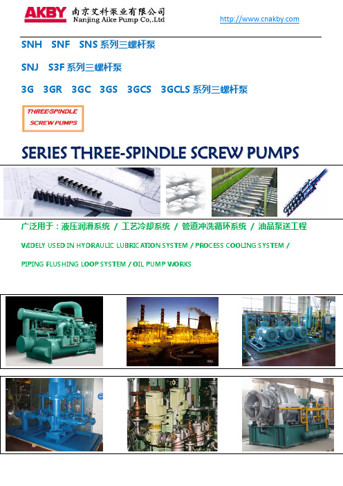
SNH SNF SNS 系列三螺杆泵 SNJ S3F 系列三螺杆泵 3G 3GR 3GC 3GS 3GCS 3GCLS 系列三螺杆泵
SERIES THREE-SPINDLE SCREW PUMPS
广泛用于:液压润滑系统 / 工艺冷却系统 / 管道冲洗循环系统 / 油品泵送工程
¾ 11 选泵流程
¾
Process of selecting pumps
¾ 13 SN系列三螺杆泵性能表
¾
Performance table of SN series three screw pumps
¾ 21 S3F系列三螺杆泵性能表
莫依诺MOYNO泵

莫依诺MOYNO泵MOYNO公司是全球著名和领先的泵业制造公司,在制造污泥泵、计量泵、卫生泵、单螺杆泵、多相流体传输系统、研磨机等方面具有国际先进的技术和服务经验。
公司产品已经广泛应用到水处理、污水处理、粉煤灰、造纸和纸浆、精细化工、食品、酿造、制药、石油化工、油气输送、水泥、玻璃等关系到国计民生的行业中。
Moyno 2000 G3 型泵◆Moyno 破桥装置配有单独的电机,运行时可以与泵转速不相同。
◆破桥装置提高了泵进给效率◆大开口式将介质堵塞情况降到最低点Moyno 2000 G1 型泵◆齿轮型万向连接装置具有较长的使用寿命。
◆转子的材料及镀层材料繁多,如陶瓷、碳化钨等。
◆定子橡胶可用于多种工况。
◆流量可达到550M3/h。
◆输送压力可达7Mpa。
Moyno 2000 G4 型泵◆万向连轴节不会阻碍介质流入泵内◆45o入口摩擦力小,介质输送更加平缓◆螺旋推进器无任何阻碍的将介质直接推进输送进泵内Moyno 2000 G2 型泵◆大开口结构可与不同规格的压滤机相匹配。
◆单螺旋进料器装置提高工作效率。
◆破桥装置有独立的驱动。
Moyno 2000 HS 型泵◆处理含固量15%-50%的市政污泥和其他非流体介质。
◆双螺旋进料器可将介质推进入口。
◆双螺旋进料口可反向转动。
◆螺旋推进器有专利权。
◆大开口的泵降低入口摩擦损失。
Moyno 1000 系列泵◆销钉式万向连接头延长其使用寿命◆与同类型泵相比,性能更加优越。
◆流量达到78m3/h。
◆输送压力达到2.4Mpa。
Moyno L系列泵◆销钉式万向连接头结构,维护简单方便。
◆此种类泵可用于特殊工况,并且在材料的选择上更广泛。
◆流量达到102M3/h。
◆输送压力达到14Mpa。
Moyno 卫生系列泵◆机械密封。
◆标准型号泵可满足3A和BISSC卫生要求。
◆直连式和大开口式结构类型。
◆流量达到78M3/h。
◆输送压力达到1.5Mpa。
Moyno 500系列泵◆结构紧凑◆动力设计可满足用户不同工况。
