POE交换机技术规范书
POE交换机说明书
PSE5000系列 POE供电以太网交换机Quick Installation GuidePower over Ethernet Switch PSE5000系列PSE6000系列用户手册V1.02User’s Manual1.概述PSE5000及PSE6000系列POE供电交换机,是非网管以太网供电交换,使用时无需配置,接上电源后即可使用。
此系列POE供电交换机提供5个10/100Base-TX或1000Base-TX自适应端口,1个为Uplink端口。
2.装箱清单小心打开包装盒,包装盒内应有以下配件:PSE5000或PSE6000系列以太网交换机 *1台;专用电源线(常规为国标电源线) *1条;快速设定手册 *1本;保修卡/合格证 *1张;如果发现有配件损坏或者短缺的情况,请及时和当地经销商或销售方联系。
PSE5000系列产品型号为:PSE5302:5埠百兆交换机,2埠 PoE(其中第4、5口支持POE)PSE5604:5埠百兆交换机,4埠 PoE(其中第2、3、4、5口支持POE)PSE6000系列产品型号为:PSE6504G:5埠千兆交换机,4埠 PoE(其中第2、3、4、5口支持POE)3.产品外观① PSE5302 POE供电交换机铭板图②PSE5604 POE供电交换机铭板图③PSE6504G POE供电交换机铭板图4. LED指示灯示意说明安装应用示意图(PSE5604 & PSE6504G)安装应用示意图(PSE5302)5.安装注意事项为保证交换机正常工作和延长使用寿命,请遵从以下的注意事项:①交换机只在室内使用,请将交换机置于通风干燥处;②交换机AC电源线需接地③交换机的接口电缆要求在室内走线,禁止户外走线,以防止因雷电产生的过电压、过电流损坏交换机;④请不要将交换机放在不稳定的箱子或桌子上,一旦跌落,会对交换机造成严重损害;当选择壁挂安装时,应将交换机及电源适配器固定好(电源部分在上),避免跌落;⑤在交换机周围应预留足够的空间(大于10cm),以便于设备正常散热;⑥请不要在交换机上放置重物;⑦请使用随产品附带的电源适配器,严禁使用其它非配套产品。
中国电信上海公司基于FTTH的PoE产品技术规范_发布稿
文件编号:中国电信上海公司基于FTTH的PoE产品技术规范(试行)1.目的为保证中国电信上海公司在基于PON技术的FTTH网络中利用PoE (Power over Ethernet,以太网供电)技术在标准的以太网数据线缆上对所连接的PON上行终端设备进行远程供电,解决PON上行终端设备附近无法取电的难题,节省部署终端设备时电源布线成本和时间,规范PoE系统的技术要求,特制定本技术规范。
2.适用范围本规范适用于采用PON技术的各类新建、扩建和改建工程。
本规范规定了在PON系统中如何利用PoE以太网供电技术为PON上行终端设备提供可靠的电源以保证其正常工作,并对PoE以太网供电系统制定了详细的技术规范。
本规范适用于基于FTTH模式下 PON上行终端设备的PoE供电系统。
本规范符合IEEE 802.3af标准中的相关技术要求。
本规范若与国家、行业相关强制性标准、规范有矛盾时,应按国家和行业相关规定执行。
3.引用文件/标准a)YD/T 1531-2006 接入网设备测试方法基于以太网方式的无源光网络(EPON)b)中国电信企业规范中国电信EPON设备技术要求(V2.1)c)IEEE 802.3af 信息技术-系统间的通信和信息交换-局域网和城域网特定要求-第3部分:CSMA/CD的接入方式及物理层规范-增补文件:使用MDI的数据终端设备功率d)GB/T 17626 《电磁兼容试验和测量技术》e)GB/T 50311-2000 《建筑与建筑群综合布线系统工程设计规范》f)GB/T 50312-2000 《建筑与建筑群综合布线系统工程施工及验收规范》4.定义/术语以太网无源光网络Ethernet Passive Optical Networks(EPON)以太网无源光网络(EPON)是一种采用点到多点(P2MP)结构的单纤双向光接入网络,由局侧的光线路终端(OLT)、用户侧的光网络单元(ONU)和光分配网络(ODN)组成。
YS-808M-POE规格书

YS-808M-POE技术规格书产品描述:YS-808-POE,是我司自主研发的二层百兆以太网POE交换机产品,支持IVL(独立VLAN学习),SVL(共享VLAN学习)灵活的网络拓扑架构;支持广播、多播unknownmulticast,和unknown-unicast包抑制控制;提供8个10/100M自适应RJ45端口,YS-808-POE机型的第8端口支持线速转发和MDI/MDIX自动翻转功能,可作为Up-link口与其他交换机进行级联。
YS-808-POE机型的1-7口都支持PoE供电功能,可以为一些基于IP的终端(如IP 电话机、无线AP、网络摄像机等)传输数据信号的同时,还能为此类设备提供直流供电的技术。
主要特点:1.超高背板带宽1.6G2.经典Realtek的以太网数据交换内核3.支持8K的MAC地址表深度4.内置DHCP Server功能,自动给AP分配IP地址,极大方便网络工程施工5.支持24V/48V PoE,可与市场上任何24V/48V POE的受电设备网络典型应用硬件规格网络标准IEEE802.3、IEEE802.3u、IEEE802.3x、IEEE802.az、CSMA\CDEthernet网络拓扑星型数据传输速率快速以太网:100Mbps(半双工),200Mbps(全双工)端口8个10/100Mbps RJ45端口,其中1-7端口支持POE供电网络介质100Base-TX:5类及以上非屏蔽双绞线(最大长度100m)指示灯每端口具有1个Link/Act指示灯每设备具有1个Up-Link指示灯每设备具有1个Power指示灯MAC地址学习自动更新性能存储转发支持3.2Gbps的背板带宽支持8K的MAC地址表深度使用环境工作温度:0℃~40℃存储温度:-40℃~70℃工作湿度:10%~90%RH,不凝露存储湿度:5%~90%RH,不凝露输入电源12V~48V(电源适配器*选配*)外形尺寸(L×W×H)225mm x121mm x34mm。
POE交换机 WS2024PE(FE) 产品规格书
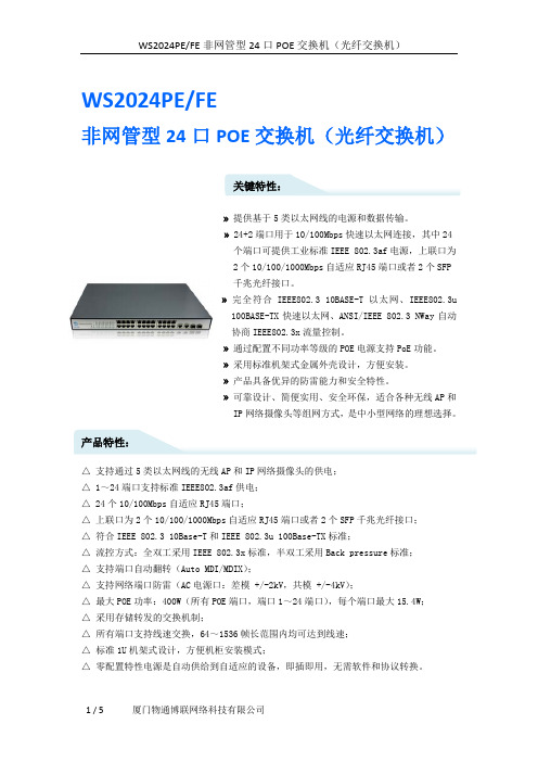
WS2024PE/FE非网管型24口POE交换机(光纤交换机)关键特性:» 提供基于5类以太网线的电源和数据传输。
» 24+2端口用于10/100Mbps快速以太网连接,其中24个端口可提供工业标准IEEE 802.3af电源,上联口为2个10/100/1000Mbps自适应RJ45端口或者2个SFP千兆光纤接口。
» 完全符合IEEE802.3 10BASE-T以太网、IEEE802.3u100BASE-TX快速以太网、ANSI/IEEE 802.3 NWay自动协商IEEE802.3x流量控制。
» 通过配置不同功率等级的POE电源支持PoE功能。
» 采用标准机架式金属外壳设计,方便安装。
» 产品具备优异的防雷能力和安全特性。
» 可靠设计、简便实用、安全环保,适合各种无线AP和IP网络摄像头等组网方式,是中小型网络的理想选择。
产品特性:△支持通过5类以太网线的无线AP和IP网络摄像头的供电;△ 1~24端口支持标准IEEE802.3af供电;△ 24个10/100Mbps自适应RJ45端口;△上联口为2个10/100/1000Mbps自适应RJ45端口或者2个SFP千兆光纤接口;△符合IEEE 802.3 10Base-T和IEEE 802.3u 100Base-TX标准;△流控方式:全双工采用IEEE 802.3x标准,半双工采用Back pressure标准;△支持端口自动翻转(Auto MDI/MDIX);△支持网络端口防雷(AC电源口:差模 +/-2kV,共模 +/-4kV);△最大POE功率:400W(所有POE端口,端口1~24端口),每个端口最大15.4W;△采用存储转发的交换机制;△所有端口支持线速交换,64~1536帧长范围内均可达到线速;△标准1U机架式设计,方便机柜安装模式;△零配置特性电源是自动供给到自适应的设备,即插即用,无需软件和协议转换。
华为云校园交换机PoE技术白皮书说明书

Huawei CloudCampus Switch PoETechnology White PaperHuawei CloudCampus Switch PoE Technology White Paper ContentsContents1 Overview (1)2 PoE Device Power Supply Modes (3)3 PoE Device Power-On Process (5)4 PoE Device Power Management (6)5 Perpetual PoE and Fast PoE (8)6 PoE Transmission Distance (9)6.1 Implementation of 200-Meter PoE Power Supply (9)6.2 Additional Description of 200-Meter PoE Power Supply (9)1 OverviewPower over Ethernet (PoE) is a technology that provides power along the 10BASE-T,100BASE-TX, 1000BASE-T, 2.5GBASE-T, 10GBASE-T, or other Ethernet cables. PoE caneffectively provide centralized power for terminals such as IP phones, WLAN Access Points(APs), chargers of portable devices, Point of Sale (POS) machines, cameras, and datacollection devices. Terminals are PoE-powered when they access the network; therefore,the indoor cabling of power supply is not required.A PoE system consists of Power Sourcing Equipment (PSE) and Powered Devices (PDs). APSE provides power, and a PD receives power from the PSE. As shown in Figure 1-1, the PoEswitch functions as a PSE, and terminals such as IP phones, WLAN APs, and cameras arePDs.Figure 1-1 Diagram of a PoE systemPoE technology facilitates installation and management, and ensures security and stability.It is widely used in scenarios such as home applications, WLAN construction, securityprotection, retail, and entertainment.Currently, IEEE 802.3af-compliant PoE provides a maximum of 15.4 W power, while IEEE802.3at-compliant PoE+ delivers up to 30 W power.Nowadays, new service types and terminals are constantly emerging, which require higherPoE input power. To meet this trend, Huawei has actively engaged in the formulation of theIP phone WLAN AP IP camera PC TV PoE SwitchPSEPDIEEE 802.3bt standard (also known as PoE++). In compliance with IEEE 802.3bt (draft), Huawei has developed and launched many PoE++ switches that provide a maximum of 60 W power.The following table describes detailed performance parameters of PoE, PoE+, and PoE++ functions.*Remarks: A Huawei PoE++ port provides up to 66 W output power. After transmission over a 100-meter standard Cate5E cable, the maximum power available at PDs is 54 W.PoE has many advantages, including the following:●Reliable: Multiple PDs are powered by one device, facilitating power backup.●Easy to deploy: Network terminals can be powered over network cables, without a need forexternal power sources.●Standards-compliant: PoE complies with IEEE 802.3af, IEEE 802.3at, and IEEE 802.3btstandards, and uses globally uniform power interfaces. This capability ensures easy networking with PDs of different vendors.2 PoE Device Power Supply Modes According to the IEEE standard, a PSE is mainly used to provide power to PDs. There are two kinds of PSEs: Midspan PSE (the PoE module is installed out of the device) and Endpoint PSE (the PoE module is integrated into the device).Huawei PoE-capable switches support built-in PoE modules and therefore belong to Endpoint PSEs. The Endpoint PSE is compatible with 10BASE-T, 100BASE-TX, 1000BASE-T, 2.5GE BASE-T, 5GE BASE-T, and 10GE BASE-T interfaces. Therefore, the Endpoint PSE is more widely used than the Midspan PSE.The Endpoint PSE can provide power using two methods: Alternative A (data pairs 1/2 and3/6) and Alternative B (data pairs 4/5 and 7/8).●Alternative A: power supply through the data pairsThe PSE supplies power to PDs through data pairs 1/2 and 3/6. The data pair 1/2 acts as the positive polarity, and the data pair 3/6 acts as the negative polarity. 10BASE-T and100BASE-T interfaces use data pairs 1/2 and 3/6 to transmit data, while 1000BASE-T interfaces use all the four data pairs (1/2, 3/6, 4/5, and 7/8) to transmit data. As DC power and data are transmitted on different frequencies, it is possible to simultaneously transmit power and data over the same wire pairs.Figure 2-1Endpoint PSE, Alternative A●Alternative B: power supply through the spare pairsThe PSE supplies power to PDs through spare pairs 4/5 and 7/8. The spare pair 4/5 acts as the positive polarity, and the spare pair 7/8 acts as the negative polarity.Generally speaking, a standard PD must support both Alternative A and Alternative B modes. However, the PSE is allowed to support only one of the two modes.Huawei PoE-capable switches can function as the PSE, and IEEE 802.3bt-compliant switch models can provide PoE++ power supply and support both the Alternative A and Alternative B modes. However, other switch models, namely those complying with IEEE 802.3af and IEEE 802.3at, support only the Alternative A mode.Figure 2-2Endpoint PSE, Alternative B3 PoE Device Power-On ProcessThe following describes the PoE device power-on sequence:1.Detection of PDs: The PSE periodically transmits a low voltage with a limited currentthrough its ports to detect PDs. If the PSE detects a resistance with a specified value, PDs that comply with IEEE 802.3af, IEEE 802.3at, or IEEE 802.3bt are connected to the PSE.2.Negotiation of power supply capability: The PSE classifies PDs and negotiates powersupply capability with PDs. Two methods are available to negotiate power supplycapability: resolving the detected resistance value or using the Link Layer Discovery Protocol (LLDP).3.Start of power supply: In less than 15 microseconds, the PSE starts to provide a lowvoltage to PDs, which is then raised to 48 V DC.4.Normal power supply: After the voltage is reached to 48 V, the PSE provides stable andreliable 48 V DC power to PDs. The power available at PDs does not exceed 30 W when the PSE supports PoE and PoE+; the power available at PDs does not exceed 60 W if the PSE also supports PoE++, in addition to PoE and PoE+.5.Disconnection of power supply: While power is being supplied, the PSE continuouslydetects the input current of PDs. The PSE cuts off the power supply to PDs and re-enters the PD detection procedure when the current of the PDs is reduced to theminimum value or increased sharply in the following situations:−The PDs are removed.−The PDs are short-circuited.−The power consumed at the PDs exceeds the power supply load of the PSE.4 PoE Device Power Management Huawei switches provide real-time power management functions that can implement management based on the real-time power of PDs.For example, if a customer chooses a Huawei PoE switch, the 24 ports on this switch support PoE/PoE+ power supply, with 370 W PoE in total. This switch does not invariably deliver 30 W for each port; instead, it manages the PoE power output of its ports based on the power consumption of PDs.You can refer to the following table to calculate how many ports can provide PoE/PoE+ power.Huawei switches provide two power supply management modes: automatic and manual.●Automatic modeA Huawei switch (as the PSE) automatically powers on and off PDs based on power supply priorities of ports. The power supply priority of ports can be set to critical, high, or low, depending on the importance of PDs connected to the ports. When the output power approximates to the full capacity of the PSE, the PSE provides power first for the PDs connected to the ports of the critical priority and then for those connected to the ports of the high priority.In the case of the same priority, Huawei S5720-EI series PoE switches preferentially provide power for the PDs connected to the ports with smaller port IDs. Other series of PoE switches of Huawei supply power based on the power-on time sequence of PDs.●Manual modeUsers can manually power on and off the PDs connected to ports. In manual mode, no power supply priority is configured. Powering on or off the PDs connected to a single portdoes not affect the PoE power supply on the other ports. When the output power approximates to the full capacity of the PSE, new PDs cannot be powered on. (PoE++ switches do not support this manual mode. For details, see the product documentation.)Huawei CloudCampus Switch PoE Technology White Paper 5 Perpetual PoE and Fast PoE5 Perpetual PoE and Fast PoEHuawei switches support the perpetual PoE technology to deliver uninterrupted PoE powersupply. A Huawei switch does not stop supplying power to PDs even when a switch card isreset by running the reboot command. This capability ensures that PDs are not powered offduring the switch reboot, eliminating the fault-triggered interruption accordingly. Huaweimodular switches currently do not support perpetual PoE.Huawei switches also support the fast PoE technology to ensure fast power supply. Huaweiswitches can supply power to PDs within 10s after they are powered on. This is differentfrom common switches that generally take 1 to 3 minutes to start to supply power to PDs.Huawei's fast PoE capability greatly shortens the service interruption time caused by powersupply interruption, and enables the switch and PDs to start almost at the same time. Thatis, after the switch is fully started, PDs can immediately get powered and function properly.Note: Both Huawei PoE++ switches and a few PoE switches support the fast PoEtechnology. For details, see the product documentation.6 PoE Transmission Distance6.1 Implementation of 200-Meter PoE Power SupplySignal-to-noise ratio (SNR) is the most important indicator for data transmission ofelectrical interfaces. To support a longer transmission distance, the SNR loss of the entirelink must be reduced as much as possible.There are multiple components and media on the transmission link of electrical interfaces,mainly including PHY chips, PCBs, interface connectors, and network cables on both ends.Huawei PoE switches have optimized SNR parameters, so that their Multi-GE electricalinterfaces support a maximum transmission distance of 200 m when they are connected tospecific Huawei APs.Detailed optimization measures include the following:●Huawei uses shielded network cables to support a maximum transmission distance of200 m. This is because the crosstalk between copper cables is serious when unshieldednetwork cables are bundled together, which has the largest impact on the SNR.Shielded network cables can be used to optimize SNR parameters.●Huawei tests the anti-interference capability of the PHY chips provided by vendors toensure that each PHY chip supports a maximum transmission distance of 200 m.Additionally, Huawei requests vendors to customize PHY driver software according toHuawei's requirements to optimize SNR parameters over a long transmission distance.●Huawei improves various signal attenuation indicators of connectors used by interfacesthat support a maximum transmission distance of 200 m to optimize SNR parameters.●Cabling from PHY chips to interface connectors must be well designed to avoid thecrosstalk between interfaces. To this end, Huawei explicitly specifies cablingrequirements in order to achieve a maximum transmission distance of 200 m.6.2 Additional Description of 200-Meter PoE Power SupplyA few Huawei PoE++ switches support a maximum transmission distance of 200 m. Otherswitch models support a maximum transmission distance of 100 m.In the case of PoE power supply distance of 200 m, the following restrictions apply:●The switches can only be connected to APs of the specified models, namely, APs with2.5GE uplinks.●Supported PoE power supply standards include 60 W PoE++, 30 W PoE+, and 15.4 wPoE. There is a 5 W power loss per 100 m.●The maximum PoE power supply distance can reach 200 m only when the followingnetwork cables are used.−Cat5E STP−Cat6 STP−Cat6A F/UTP−Cat6A STP−Cat7A few Huawei PoE++ switches can be connected to Huawei cameras over a long distance. When ports of these switches work at the 100 Mbit/s rate, the maximum transmission distance can be 200 m. When ports of these switches work at the 10 Mbit/s rate, the maximum transmission distance can be 250 m.●When the transmission distance exceeds 100 m, cables of Cat5E or higher categorymust be used.Huawei Technologies Co., Ltd.Address: Huawei Industrial Base Bantian,Longgang Shenzhen 518129 People's Republic of ChinaWebsite: Trademarks and Permissionsand other Huawei trademarks are trademarks of Huawei Technologies Co., Ltd.All other trademarks and trade names mentioned in this document are the property of their respective holders.NoticeThe purchased products, services and features are stipulated by the contract made between Huawei and the customer. All or part of the products, services and features described in this document may not be within the purchase scope or the usage scope. Unless otherwise specified in the contract, all statements, information, and recommendations in this document are provided "AS IS" without warranties, guarantees or representations of any kind, either express or implied.The information in this document is subject to change without notice. Every effort has been made in the preparation of this document to ensure。
POE交换机技术规范书

POE以太网交换机技术规范书中国联通河北省分公司二零零九年十一月一、总则1.概述1.1 本文件为中国联合通信有限公司(以下简称买方)对POE以太网交换机设备招标采购中的设备供应商(以下简称卖方)提出的技术规范书。
本规范书将作为谈判的基础。
1.2 卖方所提供的所有各项设备和系统(包括软、硬件)应符合技术标准的要求如下:(1) 符合有关标准(如ISO、ITU-T、ETSI、IETF等),卖方应在建议书中具体说明,并附上相应的详细技术资料;(2) 若卖方的设备和系统包含自己的专用标准,应在建议书中具体说明,并附上相应的详细技术资料;(3) 本文件中未给出,但ITU-T已有建议的系统设备性能和功能均应满足ITU-T 最新建议要求;(4) 待买方新的标准(中华人民共和国通信行业标准和中国联合通信有限公司相关技术要求等)制定出来后,卖方应免费修改其系统以满足要求。
(5) 中华人民共和国通信行业标准YD/T-1255-2003《具有路由功能的以太网交换机技术要求》,及其它已颁发的相关技术要求和文件,具备中国信息产业部颁发的电信设备进网许可证;(6) 国家已颁发的相关法律文件(例如招标法等)。
1.3 卖方应按照本文件的要求提供报价和详细的技术建议。
卖方提供的各项设备及系统的功能、性能应完全符合买方指明的标准,并满足或高于买方指出的要求。
对于本文件未规定的有关设备性能,卖方应提出建议,并陈述其理由。
1.4卖方应根据本文件的要求提供建议书,建议书要求采用中文书写,设备技术资料应尽量提供中文,可提供英文。
1.5规范书有关内容的澄清(1) 卖方对于规范书的疑问可以通过书面材料与买方联系。
在规定的建议书最后提交期限以前,买方将以书面材料给予答复。
有关买方答复材料的复印件也将递交所有得到技术规范书的卖方。
(2) 在技术谈判的各个阶段,买方将以书面形式要求卖方对有关问题进行进一步的技术澄清,卖方应以书面资料给予正式应答;所有各阶段的技术澄清文件都将作为合同附件。
4口百兆PoE交换机使用说明书
4口百兆PoE 交换机使用说明书V1.0.0浙江大华技术股份有限公司法律声明版权声明© 2017 浙江大华技术股份有限公司。
版权所有。
在未经浙江大华技术股份有限公司(下称“大华”)事先书面许可的情况下,任何人不能以任何形式复制、传递、分发或存储本文档中的任何内容。
本文档描述的产品中,可能包含大华及可能存在的第三人享有版权的软件。
除非获得相关权利人的许可,否则,任何人不能以任何形式对前述软件进行复制、分发、修改、摘录、反编译、反汇编、解密、反向工程、出租、转让、分许可等侵犯软件版权的行为。
商标声明●、、、是浙江大华技术股份有限公司的商标或注册商标。
●HDMI标识、HDMI和High-Definition Multimedia Interface 是HDMI LicensingLLC的商标或注册商标。
本产品已经获得HDMI Licensing LLC授权使用HDMI技术。
●VGA是IBM公司的商标。
●Windows标识和Windows是微软公司的商标或注册商标。
●在本文档中可能提及的其他商标或公司的名称,由其各自所有者拥有。
更新与修改为增强本产品的安全性、以及为您提供更好的用户体验,大华可能会通过软件自动更新方式对本产品进行改进,但大华无需提前通知且不承担任何责任。
大华保留随时修改本文档中任何信息的权利,修改的内容将会在本文档的新版本中加入,恕不另行通知。
产品部分功能在更新前后可能存在细微差异。
法律声明I前言概述本文档主要描述了4口百兆PoE交换机的产品特性和结构。
本说明书适用于以下产品型号:DH-S1500C-4ET2ET-DPWR符号约定在本文中可能出现下列标志,它们所代表的含义如下:表示能帮助您解决某个问题或节省您的时间。
表示是正文的附加信息,是对正文的强调和补充。
前言II重要安全须知下面是关于产品的正确使用方法、为预防危险、防止财产受到损失等内容,使用设备前请仔细阅读本说明书并在使用时严格遵守,阅读后请妥善保存说明书。
2.5Gbps以太网PoE交换机安装手册说明书

Enterprise Networking Solution安装手册2.5Gbps以太网PoE交换机声明Copyright © 2021 普联技术有限公司版权所有,保留所有权利未经普联技术有限公司明确书面许可,任何单位或个人不得擅自仿制、复制、誊抄或转译本手册部分或全部内容,且不得以营利为目的进行任何方式(电子、影印、录制等)的传播。
为普联技术有限公司注册商标。
本手册提及的所有商标,由各自所有人拥有。
本手册所提到的产品规格和资讯仅供参考,如有内容更新,恕不另行通知。
除非有特殊约定,本手册仅作为使用指导,所作陈述均不构成任何形式的担保。
I声明II相关文档 相关文档安装手册简介《安装手册》主要介绍了2.5Gbps以太网PoE交换机的硬件特性、安装方法以及在安装过程中应注意事项。
本手册包括以下章节:第1章:产品介绍。
简述交换机的基本功能特性并详细介绍外观信息。
第2章:产品安装。
指导交换机的硬件安装方法以及注意事项。
第3章:硬件连接。
指导交换机与其他设备之间的连接及注意事项。
附录A:技术参数规格。
说明:在安装设备之前及安装设备过程中为避免可能出现的设备损坏及人身伤害,请仔细阅读本手册相关内容。
阅读对象本手册适合下列人员阅读:网络工程师网络管理人员约定在本手册以下部分,如无特别说明,均以TL-SH1005PB为例介绍,所涉及的产品图片仅为示意说明,请以实际机型为准。
本手册采用了如下几种醒目标志来表示操作过程中应该注意的地方,这些标志的意III阅读对象目录第1章 目录第1章 产品介绍 —————————————011.1 产品简介 (01)1.2 产品外观 (01)第2章 产品安装 —————————————032.1 物品清单 (03)2.2 安装注意事项 (03)2.3 安装工具准备 (06)2.4 产品安装 (06)第3章 硬件连接 —————————————073.1 连接RJ45端口 (07)3.2 连接电源 (07)3.3 设备初始化 (08)附录A 技术参数规格 ———————————09IV目录2.5Gbps以太网PoE交换机安装手册01产品介绍第1章 产品介绍1.1 产品简介TL-SH1005PB是普联技术有限公司自主研发的2.5Gbps以太网PoE交换机。
海康威视经济型POE交换机产品手册说明书

经济型POE交换机产品简介DS-3E系列POE交换机支持5/8/16/24口百兆PoE电口,可通过网线直接供电,PoE自适应802.3af(15.4W)和802.3at(30W)标准,整机PoE最大输出功率为58/120/230/370W,通过普通的5类双绞线即可为AP、IP摄像头、IP电话等PoE受电设备同时传输电力和数据。
设备支持网络延长(EXTEND)模式,开启后,使用超五类及以上网线时,对应端口的数据传输和供电距离最远可达250米;PoE支持8芯供电技术,有效降低电源线路损耗;支持重要端口数据保障功能,对于重点区域的数据或视频,优先保证及传输;智能型支持VLAN、链路汇聚、QoS、STP防环、SNMP等智能管理功能,可减少项目施工难度和施工时间,最大程度的节省工程项目成本,保护用户投资。
整机全金属设计,结构坚固、使用方便,可靠性好,适用于园区、公安、楼宇等多种监控场景。
DS-3E0105P-EDS-3E0109P-E&DS-3E0109P-E(B)DS-3E0318P-EDS-3E0326P-EDS-3E1310P-EDS-3E1318P-EDS-3E1326P-E订货型号功能特性●支持802.3af/at PoE标准●支持PoE 8芯供电技术,降低网线电源损耗●支持重要端口数据保障●支持EXTEND模式,延长网线传输至250m●支持buffer优化,保证视频数据传输●支持VLAN配置(智能型支持)●支持端口汇聚(智能型支持)●支持STP、组播、端口镜像(智能型支持)●支持QoS(智能型支持)●支持SNMP网络管理(智能型支持)●支持WEB管理(智能型支持)●存储转发交换方式;●支持IEEE802.3、IEEE802.3u、IEEE802.3x网络标准●平均无故障时间MTBF≥10万小时;●全金属封闭结构;●桌面、机架式设计,安装简便技术参数非网管型硬件规格智能型硬件规格智能型软件规格组网应用DS-3E1318P-EDS-3E1318P-EDS-3E1318P-EDS-3E1318P-EDS-3E2528电视墙POE IPCPOE交换机汇聚交换机NVR客户端存储服务器监控组网示意图。
PoE交换机快速入门说明书

PoE交换机快速入门V1.011项目名称数量单位1 主机 1 台2* 电源线 1 根3* 电源适配器 1 个4* 橡胶脚垫 4 个5* 螺钉 4 个6* 挂耳 1 对7 用户资料 1 份备注:根据产品不同型号和不同版本,随箱附件可能有变动,请以实际为准。
*表示可选,仅部分款型随机附带。
2不同款型交换机外观会有所不同,具体请以实物为准。
2.1 前面板4口PoE交换机8口PoE交换机1.G1/SFP1状态指示灯2.G2状态指示灯3.电源状态指示灯4.整机PoE功率指示灯5.PoE端口状态指示灯6.优先级端口7.千兆以太网接口8.光模块接口9.PoE端口10.Link/Act状态指示灯11.百兆以太网接口2.2 后面板4口和8口PoE交换机16口和24口PoE交换机3不同款型指示灯颜色会有所不同,具体请以实物为准。
指示灯颜色描述POWER 绿色灭:交换机未通电常亮:交换机通电正常 PoE 绿色灭:PoE 端口未供电 常亮:PoE 端口正常供电 Link/Act 绿色灭:没有连接网络设备 常亮:连接到网络设备 闪烁:正在传输数据PoE-MAX 绿色/黄色灭:整机PoE 输出功率低于总功率的80%常亮:整机PoE 输出功率高于总功率的85%44.1 工具准备绝缘手套、螺丝刀、螺钉4.2 安装步骤4.2.1 桌面安装将脚垫粘贴到机壳底部四角对应的凹槽内,然后将交换机正置,放在足够大且干净平稳的桌面上。
4.2.2 壁挂式安装根据设备底部的定位孔位置在墙壁上固定两颗螺钉。
然后对准交换机的两个定位孔,把设备平稳地挂在螺钉上。
4.2.3 机架式安装1.检查机架的接地与平稳性,使用随机附带的螺钉将两个挂耳固定到交换机的两侧。
2.将交换机放置于机架内的适当位置,用螺钉(需自备)将挂耳固定到机架两侧的导槽上,确保交换机平稳地安装到机架上。
注:16口和24口PoE交换机支持桌面安装与机架式安装,4口和8口PoE交换机支持桌面安装和壁挂式安装。
JetNet 3705 工业 PoE 交换机使用说明说明书
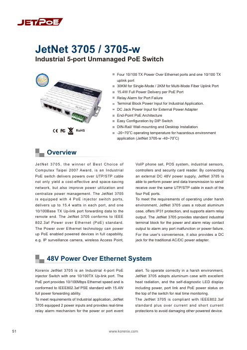
51OverviewFour 10/100 TX Power Over Ethernet ports and one 10/100 TX uplink port30KM for Single-Mode / 2KM for Multi-Mode Fiber Uplink Port 15.4W Full Power Delivery per PoE Port Relay Alarm for Port FailureTerminal Block Power Input for Industrial Application. DC Jack Power Input for External Power Adapter End-Point PoE Architecture Easy Configuration by DIP SwitchDIN-Rail/ Wall-mounting and Desktop Installation-20~70oC operating temperature for hazardous environment application (JetNet 3705-w -40~70oC)JetNet 3705, the winner of Best Choice of Computex Taipei 2007 Award, is an I ndustrial PoE switch delivers powers over UTP/STP cable not only yield a cost-effective and space-saving network, but also improve power utilization and centralize power management. The JetNet 3705 is equipped with 4 PoE injector switch ports, delivers up to 15.4 watts in each port, and one 10/100Base TX Up-link port forwarding data to the remote end. The JetNet 3705 conforms to I EEE 802.3af Power over Ethernet (PoE) standard. The Power over Ethernet technology can power up PoE enabled powered devices in full capability, e.g. IP surveillance camera, wireless Access Point,VoI P phone set, POS system, industrial sensors, controllers and security card reader. By connecting an external DC 48V power supply, JetNet 3705 is able to perform power and data transmission to send/receive over the same UTP/STP cable in each of the four PoE ports.To meet the requirements of operating under harsh environment, JetNet 3705 uses a robust aluminum case, offers IP31 protection, and supports alarm relay output. The JetNet 3705 provides standard industrial terminal block for the power and alarm relay contact output to alarm any port malfunction or power failure. For the user's convenience, it also provides a DC jack for the traditional AC/DC power adapter.Korenix JetNet 3705 is an I ndustrial 4-port PoE injector Switch with one 10/100TX Up-link port. The PoE port provides 10/100Mbps Ethernet speed and is conformed to IEEE802.3af PSE standard with 15.4W full power forwarding ability.To meet requirements of Industrial application, JetNet 3705 equipped 2 power inputs and provides real-time relay alarm mechanism for the power or port eventalert. To operate correctly in a harsh environment, JetNet 3705 adopts aluminum case with excellent heat radiation, and the self-diagnostic LED display including power, port link and PoE power status on the top of the switch for real time monitoring.The JetNet 3705 is compliant with I EEE802.3af standard plus over current and short current protections to avoid damaging other powered device.Industrial 5-port Unmanaged PoE SwitchJetNet 3705 / 3705-w48V Power Over Ethernet SystemRoHSIndustrial PoE SwitchIndustrial PoE SwitchIP67/68 Ethernet Switch RackmountManaged Switch Gigabit Switch Redundant Switch Entry-Level Switch Networking ComputerCommunication Computer Ethernet I/O Server Serial Device Server Media Converter MultiportSerial Card SFP Module Din Rail Power Supply52High Layer SwitchMonitor & Control CenterData & DC48VPoE IP Camera Wireless APCeiling Type PoE IP CameraIP Surveillance AppicationOutdoor2 x DC48V InputAlarm Relay OutputJetNet 3705Dimensions (Unit –mm)ApplicationSpecificationOrdering InformationJetNet 3705 Industrial 5-port Unmanaged PoE Switch Includes:JetNet 3705Wall mount panel kitsQuick Installation GuideCD User manual Power RequirementsSystem PowerInput Voltage:48VDC or -48VDC, dual power inputs in terminal block connectionAC /DC Power Adapter DC 48V/1.6A (option)One DC jack for AC/DC power adapterReverse Polarity Protection: PresentPower Consumption:6.5Watts without PD loading70Watts with PD full loadingMechanicalInstallation: DIN-Rail mount or Wall MountCase: IP-31 grade aluminum metal caseDimension:33.8 mm (H) x 164.8 mm(W) x 108 mm (D) EnvironmentalOperating Temperature: -20 ~70C(JetNet 3705-w -40~70C)Operating Humidity: 0% ~ 95%, (non-condensing) Storage Temperature: -40 ~ 80 CStorage Humidity: 0%~ 95%, (non-condensing) Regulatory ApprovalsHi-Pot : 1.2KV testing passed on port to powerEMI: FCC Class A, CE/EN55022 Class AEMS:EN61000-4-2, EN61000-4-3, EN61000-4-4, EN61000-4-5, EN61000-4-6, EN61000-4-8, EN61000-4-11Safety: CE/EN60950Shock: IEC60068-2-27Vibration: IEC60068-2-6Free Fall: IEC60068-2-32MTBF: 517,810 Hours, MIL-HDBK-217F GB standard Warranty: 5 yearsTechnologyStandard:IEEE802.3 10Base-TIEEE802.3u 100Base-TXIEEE802.3af Power over EthernetIEEE802.3x flow controlSwitch Technology: Store and forward technology andwith 3.2Gbps internal switch fabric.Aggregate System Throughput: 1.49MppsMAC Address: 1K MAC address TablePacket Buffer: 512KbitsPower over Ethernet port:Port 1~4, with 15.4w full power forwarding abilityRJ-45 pin assignment: TX (3,6), RX (1,2), V+ (4,5), V-(7,8)PoE output voltage: DC 44~57VInterfaceNumber of Ports: 4 x 10/100 Base-TX with Power overEthernet injector ,Auto MDI/MDI-X, Auto-Negotiation1 x 10/100 Base-TX uplink portConnectors:10/100 Base-TX: RJ-45Power/Relay: 6-Pin Terminal BlockDC-JackCables:10Base-T: 4-pair UTP/STP Cat. 3, 4, 5 cable,EIA/TIA-568 100-ohm(100m)100Base-TX: 4-pair UTP/STP Cat. 5 cable,EIA/TIA-568 100-ohm(100m)Port Alarm DIP Switch:DIP 1~5: Enable (On) or disable (Off) port link downalarm from port 1 to port 5.DIP 6: Enable (On) or disable (Off) power alarm.Diagnostic LED:Power x 3 (Green), Fault x 1(Red)PoE x 4(Green),Link/Activity x 5 (Green on/GreenBlinking)@100Mbps, (Yellow on/Yellow Blinking)@10MbpsOptional AccessoriesDC 48V Din-Rail Power: DR-75-48DC 48V Din-Rail Power: MDR-100-4853。
全千兆云管理交换机全千兆云管理PoE交换机用户手册说明书

全千兆云管理交换机全千兆云管理PoE交换机用户手册1910040966 REV1.0.0声明Copyright © 2022 普联技术有限公司版权所有,保留所有权利未经普联技术有限公司明确书面许可,任何单位或个人不得擅自仿制、复制、誊抄或转译本手册部分或全部内容,且不得以营利为目的进行任何方式(电子、影印、录制等)的传播。
为普联技术有限公司注册商标。
本手册提及的所有商标,由各自所有人拥有。
本手册所提到的产品规格和资讯仅供参考,如有内容更新,恕不另行通知。
除非有特殊约定,本手册仅作为使用指导,所作陈述均不构成任何形式的担保。
目录第1章用户手册简介 (1)1.1目标读者 (1)1.2产品简介 (2)第2章设备管理 (5)2.1通过本地WEB管理交换机 (5)2.1.1登录准备 (5)2.1.2登录步骤 (5)2.1.3更改交换机登录IP (7)2.2PC版本商用网络云平台管理 (8)2.3通过手机商云APP管理 (12)第3章端口管理 (15)3.1端口通用配置 (15)3.1.1启用/禁用端口 (15)3.1.2配置端口速率/双工模式 (15)3.1.3配置端口流量控制功能 (16)3.2配置端口监控功能 (16)3.2.1端口监控介绍 (16)3.2.2端口监控配置实例 (17)3.3.1环回保护介绍 (18)3.3.2环回保护配置实例 (19)3.4配置端口汇聚功能 (20)3.4.1端口汇聚介绍 (20)3.4.2端口汇聚配置实例 (21)3.5配置MAC地址搜索功能 (22)3.5.1MAC搜索介绍 (22)3.5.2MAC地址搜索配置实例 (22)3.6配置端口线缆检测功能 (23)3.6.1线缆检测介绍 (23)3.6.2线缆检测配置实例 (24)第4章VLAN (25)4.1配置802.1Q VLAN (25)4.1.1802.1Q VLAN介绍 (25)4.1.2802.1Q VLAN配置方法 (26)4.1.3802.1Q VLAN配置实例 (27)4.2配置Port VLAN (31)4.2.1Port VLAN介绍 (31)4.2.2Port VLAN配置实例 (31)4.3.1MTU VLAN介绍 (33)4.3.2MTU VLAN配置实例 (33)第5章服务质量 (35)5.1配置QoS优先级模式 (35)5.1.1QoS三种优先级介绍 (35)5.1.2QoS优先级配置实例 (37)5.2配置带宽控制功能 (38)5.2.1带宽控制介绍 (38)5.2.2带宽控制配置实例 (38)5.3配置风暴抑制功能 (40)5.3.1风暴抑制介绍 (40)5.3.2风暴抑制配置实例 (41)第6章网络安全 (43)6.1配置DHCP侦听功能 (43)6.1.1DHCP侦听介绍 (43)6.1.2DHCP侦听配置实例 (43)第7章PoE (45)7.1配置PoE功能 (45)7.1.1PoE介绍 (45)第8章系统配置 (48)8.1云管理 (48)8.2查看系统信息 (48)8.3配置IP地址 (48)8.4设置用户名和密码 (49)8.5配置系统备份 (49)8.6如何还原系统配置 (50)8.7重启系统 (50)8.8恢复系统 (50)8.9升级系统 (51)第1章 用户手册简介本手册详细介绍登录Web管理交换机配置各项功能的方法,以及使用管理软件的方法。
POE技术白皮书

POE技术白皮书一、POE介绍POE是什么?POE:Power Over Ethernet ,顾名思义是以太网供电,也可以被称为基于局域网的供电系统(POL, Power over LAN )或有源以太网( Active Ethernet),它保持了与现存以太网系统和用户的兼容性。
这也是第一个关于电源分配的国际标准。
POE实现了什么?POE在现有的以太网Cat.5布线基础架构不作任何改动的情况下,可以为一些基于IP 的终端(如IP电话机、无线局域网接入点AP、网络摄像机等)传输数据信号,同时还能为此类设备提供直流供电。
POE产生的背景在一些特殊的应用场合,如果使用传统的带有电源线或者变压器的设备是会十分的不方便。
比如无线接入设备(如AP或者是无线路由器)通常要安置在天花板上,但在这个地方很难找到一个合适的交流电输出接口。
802.3af标准制订的规范就是为这些设备不再需要电源线接口而诞生。
同时人们发现这样在开支上面能够节省很大一部分,因此POE技术迅速的发展了起来。
POE的优势IEEE 802.3af标准是通过以太网数据线对或备用线对来实现以太网设备供电,从而摆脱了采用交流适配器所带来的麻烦。
以太网供电不仅去除了讨厌的壁式变压器,还有助于推出一整套新的设备,这些设备结合了数据和电源接口,并可对现有的10、100或1000Mbps以太网设备后向兼容。
802.3af突破了以太网的应用,它主要是一个电源传输协议,而不是数据协议。
同时POE出现也节省了布线的工作量。
以太网网线供电已经在市场上广泛应用了,特别是在IP电话、无线局域网和IP安全市场。
这项应用的支持者称,由于不用安装另外的电源线和电源插座,这项技术可以节省很大一部分的安装费用同时也方便管理者进行管理。
同时它还可在部署本地交流电源较为困难的场所安装网络连接设备,从而提供了更大的灵活性。
如果采用传统的交流供电方式,会产生电磁干扰,而双绞线容易受到磁场的干扰。
PoE交换机使用说明书
INTRODUCTIONThis manual is to be used for ensuring users use the product correctly through a manual, in order to avoid risks or damage of their property happens when they are operating. Before using the product, please read the product manual carefully and keep it safe for future reference.OverviewThis document is applicable for the PoE switch instruction.AgreementPrecautions for safety use△!DANGER◆In the processing of the installation and usage of this product, strictly abide by theregulations of the national and local electrical safety is necessary.◆The plug or socket of the device is the equipment that can disconnects from the power. DONOT block it, for easy insertion and removal.◆The external conductors connecting the equipment to the hazardous live terminals need tobe installed by professionals◆The protective grounding of the equipment should be connected to the protectivegrounding of the building equipment.◆Must cut off the power supply of the device, when it is connecting cables, disassembling, orinstalling devices. DO NOT operate with power on.◆The device is not suitable for the usage scenario where children may be present.◆This product contains button batteries, if that are swallowed, it will cause a serious internalburn to lead to DEATH. Children should stay away from new and used batteries.△!CAUTION◆Please use a power adapter which produced by the authorized manufacturer.◆Keep the device placed horizontally on the desktop when you are using◆The device should away from an exposed fire sources, for example a lit candle.◆The device shouldn’t suffer from water droplets or splashes. Place any liqu id (such as watercups) on the equipment is strictly prohibited.Chapter 1 Product introductionLite managed PoE switch, hereinafter referred to as the “device”, is a Layer 2 PoE network switch that provides advanced technology of Ethernet PoE power-supply based on meeting high-performance access requirements. The product supports Client Management and achieves such functions of the security network as visualized topology management and port management. With high reliability, easy to install, and easy to maintain, this PoE is equipped with multiple access ports to achieve fast switching, and also it is suitable for devices that have access to a small-scale LAN.1.1 Install and Power upPlace the switch on a smooth table, connect the power cable, plug it, and turn on the power supply. After being powered on, the switch is initializing automatically while the port indicator is flicking then turns off, and the system initialization is completed.△!CAUTION:1. DO NOT place heavy objects on the switch and ensure that the switch has good ventilation and heat dissipation.2. Please power OFF before inserting or removing the adapter.3. Please check the power supply. If the initialization does not comply with the above.1.2 Appearance part instructionsThis chapter describes the detailed instructions of the switch front and rear panels, and the LED indicators.1.2.1 Front PanelDiagram of front Panel1.Indicator Light△!CAUTION:The priority of the PoE port power supply is as follows: The larger the port number, the lower the priority. If the gross power of all powered PoE equipment is higher than the maximum output power of the device, the switch will cut off the power supply for the largest port on the connected device. For example, ports number 1,2,5,8 are in the progress of a 14W normal power supply, and the total power supply of the system is 56W. If now a powered equipment with 15W is connected to one of the ports, the system will cut off the power supply automatically for port 8, because the power supply is overloaded. That is means, ports 1, 2, and 5 are still supplied with14W power, the new ports supplied with 15W, but Ports 8 will no longer be supplied with the power.1.Reset ButtonRed port is a port with a high priority for up-going forwarding, it is identified an area in red on the device, and has the below privileges:◆Under the circumstance of up-going congestion, data is transmitted firstly on the ports ofthis area.◆When the gross power of PoE has exceeded the limit, give priority to the output power ofports in the area.3.Uplink Port4 Port switches support 10/100Mbps full-duplex communication, and 8 Port switches support 10/100/1000Mbps full-duplex communication, but do not provide PoE function.1.2.2 Rear PanelDiagram of Rear Panel1.Power InterfacePlease use a 48V power supply to connect the powered adapter, if the power supply does not match, the switch will be damaged.2.Lightning protection grounding poleLocated on the left of the power interface, it must be connected to a lightning protection to prevent the device from a lightning damage.Chapter 2 ADD DEVICEThe device can be configured and managed through the VMS Pro client software, including network parameter configuration, port configuration, and network topology display and searching.The device used for the first time must be activated first, set up the login password. Please install the VMS Pro client first and follow the instructions.Operating steps1.In the interface of Video Management ---> Auto Search, select the device, Click for activation.2.Set up and confirm the login password for the device on the pop up menu page, then edit the network information to let it have same network segment as the PC which installs VMS Pro client.3.Click “Save”, the device is activated and add suc cessfully.○i Explanation:Before activating the device, please ensure the device IP address, subnet mask and gateway are under same network segment as the PC which installs VMS Pro client. So that the device can be added to the client for management.Chapter 3 Remote Configuration3.1 System Configuration3.1.1 Device InformationSelect Remote configuration ---> Configuration ---> Information, basic device information will be displayed, including the device name, model, number of ports, firmware version, MAC address, and port information, etc.3.1.2 Device MaintenanceYou can reboot the device, restore the default Settings, download logs, and upgrade. Operating Steps1.Select Remote config --->Management ---> System management,have access to the Maintenance page.2.Select function buttons to achieve different functionsSystem default All parameters are restored to factory Settings. After the restoration, the device needs to be reactivated.SystemRebootRemote reboot device.DownloadLog The serial port logs from the switch can be downloaded, you can check the problems through analyzing the error types of the switch.UpgradeClick, Select upgrade documents, click upgrade, the device upgrade.Current Progress shows the upgrade progress.3.2 Network ConfigurationSelect Remote config ---> Internet, Network parameters can be configured for different clients. Network parameters include IPv4 address, subnet mask, gateway address, and port.○i Explanation:After IPv4 addressed is reset, it will cause the device IP and the PC IP that are not in the same network segment, so the device management and configuration do not work. Planning the device's IP address at first is suggested when the device being used for the first time.3.3 Port ConfigurationSelect Remote Configuration ---> Port to proceed with the related configuration.○i Explanation:The supported functions of the device itself exists difference, details is subjected to the actual interface.3.3.1 Attributes ConfigurationIn Attributes Configuration interface, you can configure the port rate, duplex mode, scream control, and on-off.Rate Include automatic negotiation 10Mbps, 100Mbps, 1000Mbps rates, etc. auto-negotiated is defaultDuplex This version only support auto-negotiated modeStream Control When in the processing of the function of the port scream control, after the stream control is opened, it can avoid packet loss effectively. The function is the default open.On-off Port on-off, after tu rn off, the port haven’t transmitted data, other device is still supplied by power.3.3.2 Remote ConfigurationDevices that support the remote function, turn on or turn off the switch, the port of the remote function can be turned on or off.When the remote function has been turned on, the transmission distance can reach 250m.After the remote function has been turned on, the port rate will be matched to 10Mbps; after it has been turned off, the port rate will be restored to auto-negotiated.3.3.3 PoE Port ConfigurationFor the devices that support the PoE function, the PoE function can be turned on for providing the power to other PD devices.Turn on or off the PoE, data transmission is not influenced.3.4 Log managementIf the device is abnormal or need to check the operation records, the log of device can be checked at the interface of log searching.Operating Steps1.Select Remote Configuration ---> Log,enter the page of the log.Main Type When searched by the type, the system, operating, account, warn, that can be selected in the main type, a total of 4.Start Time Searching Start Time for log End Time Searching End Time for logSub Type Sub Type can select the related type according the different type of Main TypePort Searching the log in corresponding port1.Click Export,select Export path.2.Give the exported document a name, format is stored by .xlsx, log back-up has been finished.3.5 User managementDevic e only support one admin user, can’t add or delete, but can change the password. Operating StepsSelect Remote Configuration ---> User, enter the edit interface of userPasswordIt consists of two or more combinations of 8-16 digits, lowercase letters, uppercase letters or special characters. Passwords are divided into three levels: weak, medium, and strong. To protect your personal privacy and corporate data, and avoid network security issues on your device, it is recommended that you set a strong password that complies with security standards.Chapter 4 Topology presentationIn the interface of topology presentation, the relation of topology in different added devices can be viewed by the client, and related configuration can be operated.4.1 Related operatingSelect the device which needs checked, selected Control Panel ---> Topology presentation, enter the interface of topology.Interface Description⚫Imputing the alias or IP of the device at the top left corner, corresponding topology graph can be viewed.⚫The upper right corner show the meaning of different icon color, and icons of export, refresh topology graph and path.⚫Zoom in and zoom out the topology at the bottom of right corner, or zoom in and out directly through scrolling the muse wheel.⚫The level of the display layer of topology graph can be set up at the bottom left corner.○i Explanation:Enter the interface of topology graph for the first time, if no topology graph is displayed, please click refresh and try again.Related Operating/Icons descriptionAction/Icon Operating DetailsDouble-click Device Look over the details ofdeviceThe type of the device and the information of IP,Panel status, and Port are displayed.Right-click DeviceLook over the devicestatusSkip to the interface of device status, and see detailsat device status.Run alarm processing The information of alarm and event is displayed, andperform alarm elimination operationRun remoteconfigurationSkip to the interface of remote configuration, and seedetails at Remote Configuration.Modify the devicenameModify the name on the interface of topologySet as root node Set the current device to the root node in thetopologyUpgrade device Supports the connected NVR, DVR, and IPC upgrades Export topology graph Select the export path, and export the currenttopology graphShow Path Select IPC and current device, the path between theselected device can be displayedRefresh topology graph Refresh the interface of topology and display it4.2 Topology SettingOperating stepsClick which at the interface of the bottom of the left corner to proceed with the basic setting of the topology.⚫Set the display level:1~10;⚫Click “OK”, save the setting.○i Explanation:After the setting changed, needs to be clicked to refresh for displaying the latest topology.Chapter 5 Device StatusIn the interface of topology graph, right-click the device, then click the Device Status, the device using condition, panel status, port status, PoE port status, and the port statistics can be looked over.⚫Port Status:Check the condition of the port rate, the duplex mode, and the scream control ⚫Port Statistics:Check the Bytes that sent/received by the port, the packets count, the rate, and the peak rate. Set an interval of refresh automatically, and run Refreshing or Clearing data statistics by hand.⚫PoE Port Status:Check the port switch and output power corresponding to the port number.。
POE网络交换机用户手册说明书
Contents1.Introduction (3)2.Hardware Descriptions (4)2.1 Front Panel (4)2.2 LED Indicators (4)2.3 Rear Panel (4)2.4 Specification (5)3.Getting Started (5)3.1 Management Options (5)3.2 Using Web-based Management (6)4.Configuration (7)4.1 Welcome (7)4.2 Administrator (8)4.3 Port Management (12)4.4 VLAN Setting (15)4.5 Per Port Counter (17)Per Port Counter -> Port Counter (17)4.6 QoS Setting (18)4.7 Security (19)4.8 Spanning Tree (21)4.9 Trunking (23)4.10 DHCP Relay Agent (23)4.11 Backup/Recovery (25)4.12 Miscellaneous (26)4.13 SNMP Settings (26)4.14 Logout (27)4.15 PoE Settings (27)1. IntroductionPower-over-Ethernet (PoE) eliminates the need to run DC power to other devices on a wired LAN. Using a Power-over-Ethernet system, installers need to run only a single Category 5 Ethernet cable that carries both power and data to each device. This allows greater flexibility in the locating of network devices and, in many cases, significantly decreases installation costs.There are two system components in PoE - the PSE (Power Sourcing Equipment) and the PD (Powered Device). The IEEE 802.3af/at specification defines PSE as a device that inserts power onto an Ethernet cable. The PSE may be located at the switch (End-span configuration). or it may be a separate device located between the switch and the PD (Mid-span configuration). The PD is the natural termination of this link, receiving the power, and could be an IP phone, a WLAN access point, or any other IP device that requires power. The current is transmitted over two of the four twisted pairs of wires in a Category-5 cable.Power-over-Ethernet follows the IEEE 802.3af/at specification and is completely compatible with existing Ethernet switches and networked devices. Because the Power Sourcing Equipment (PSE) tests whether a networked device is PoE-capable, power is never transmitted unless a Powered Device is at the other end of the cable. It also continues to monitor the channel. If the Powered Device does not draw a minimum current, because it has been unplugged or physically turned off, the PSE shuts down the power to that port. Optionally, the standard permits Powered Devices to signal t0 the PSEs exactly how much power they need.The PoE switch is a multi-port fast Ethernet switch that can be used to build high-performance switched workgroup networks. This switch is a store-and-forward device that offers low latency for high-speed networking. It also features a ‘store-and-forward switching’ scheme that allows the switch to auto-learn and store source addresses in a 8K-entry MAC address table. The switch is targeted at workgroup, department or backbone computing environments.2. Hardware Descriptions2.1 Front PanelThe front panel consists of LED indications, reset button and 16/24x10/100 PoE ports + 2x10/100/1000 Uplink pots.2.2 LED IndicatorsPower LED: The Power LED lights up when the switch is connected to a power source.Link/Act LED:Green (for megabit ports): Indicates that the port is running at 100M.Green (for gigabit ports): Indicates that the port is running at 100M.Blinking: Indicates that the switch is either sending or receiving data to the port.Light off: No link.PoE LED:Green: Indicates the PoE powered device (PD) is connected and the port supplies power successfully.Light off: Indicates no powered device (PD) connected.Reset: By pressing the Reset button for 10 seconds the switch will change back to the default configuration and all changes will be lost.2.3 Rear PanelThe rear panel view of the switch consists of a AC power connector, Power Switch and Glass Fuse(AC250V 10A,Φ5*L20mm).2.4 Specification3. Getting StartedThis chapter introduces the management interface of the switch.3.1 Management OptionsThe Switch can be managed through any port on the device by using the Web-based ManagementEach switch must be assigned its own IP Address, which is used for communication with Web-Based Management. The PC’s IP address should be in the same range as the switch. Each switch can allow only one user to access the Web-Based Management at a time.Please refer to the following installation instructions for the Web-based Management.3.2 Using Web-based ManagementAfter a successful physical installation, you can configure the switch, monitor the network status, and display statistics using a web browser.Connecting to the SwitchYou will need the following equipment to begin the web configuration of your device:⏹ A PC with a RJ-45 Ethernet connection⏹ A standard Ethernet cableConnect the Ethernet cable to any of the ports on the front panel of the switch and to the Ethernet port on the PC. Login Web-based ManagementIf DHCP is not enabled on the local LAN, the switch will be able to log in to the web page with 192.168.2.1 after 2 minutes. If DHCP is enabled, the DHCP server (router) will assign the address to the switch, and use DHCP to log in to the switch. Login to the switch web page.In case no DHCP server, In order to login and configure the switch via an Ethernet connection, the PC must have an IP address in the same subnet as the switch. For example, if the switch has an IP address of 192.168.2.1, the PC should have an IP address of 192.168.2.x(where x is a number between 2 ~ 254), and a subnet mask of 255.255.255.0. Open the web browser and enter 192.168.2.1 (the factory-default IP address) in the address bar. Then press <Enter>.When the following logon dialog box appears, enter the username and password then click OK. The default username is admin and password is system.Note:If the DHCP server (routing) to the switch assigned address, you can use the Auto Discovery tool to query the switch ip4. ConfigurationThe features and functions of the switch can be configured for optimum use through the Web-based Management.4.1 WelcomeAfter a successful login you will see the screen bellows:4.2 AdministratorAdministrator -> Authentication ConfigurationHere you can enter a new Username/Password and confirm it.If the switch is used to open the DHCP environment, the switch will automatically obtain an IP address from a DHCP server, the switch for the landing web page.The factory defaultIP address: 192.168.2.1Username: adminPassword: systemAdministrator -> System IP ConfigurationThere are two ways for the switch to obtain an IP address: Static and DHCP (Dynamic Host Configuration Protocol).If the switch is used to open the DHCP environment, the switch will automatically obtain an IP address from a DHCP server, the switch for the landing web page, as shown below:When using static mode, the IP address, Subnet Mask and Gateway can be manually configured. When using DHCP mode, the Switch will first look for a DHCP server to provide it with an IP address (including network mask and default gateway) before using the default or previously entered settings. By default the IP setting is static mode with IP address is 192.168.2.1 and subnet mask is 255.255.255.0Administrator -> System StatusComment: By entering a Comment, the device can more easily be recognized on the LAN.Idle Time Security: It controls the idle time-out period for security purposes, when there is no action for a specific time span in the Web-based Management. If the current session times out (expires), the user is required a re-login before using the Web-based Management again. Selective range is from 3 to 30 minute, and the defaultsetting is 5 minutes.Administrator -> Load default settingProvide a safe reset option for the switch. All configuration settings in non-volatile RAM will be reset to factorydefault and then the switch will reboot.You must enter the password of device in order to determine the firmware needs to be updated.After a correct password the switch will erase the old firmware first.After completing the erase you will see the screen bellows. Specify the Firmware Path (or Browse for one) that you are going to use, and then click Update. The state will show ‘OK’ after completion and ‘Fail’ is firmware upgrade fails or cannot be completed for any reason.Administrator -> Reboot DeviceProvide a safe way to reboot the system. Click Reboot to restart the switch.4.3 Port ManagementPort Management -> Port ConfigurationIn this page, the status of all ports can be monitored and adjusted for optimum configuration.Enable: Enable or disable the port’s connectionAuto-Nege: Enable or disable port auto-NDI/MDIXSpeed: Copper connections can operate in Forced Mode settings (1000M Full, 100M Full, 100M Halt, 10M Full, 10M Half), Auto, or Disabled. The default setting for all ports is Auto.Duplex: Copper connections can operate in Full-Duplex or Half-Duplex ModeAddr. Learning: Enable or disable port learning MAC address.Port Management -> Port MirroringPort Mirroring is a method of monitoring network traffic that forwards a copy of each incoming and/or outgoing packet from one port of the Switch to another port where the packet can be studied. This enables network managers to better monitor network performances.TX (transmit) mode: Duplicates the data transmitted from the source port and forwards it to the Target Port. Click “all” to include all ports into port mirroring.RX (receive) mode: Duplicates the data that received from the source port and forwards it to the Target Port. Click “all” to include all ports into port mirrori ng.Both (transmit and receive) mode: Duplicate both the data transmitted from and data sent to the source port, and forwards all the data to the assigned Target Port. Click “all” to include all ports into port mirroring.The target ports will stop mirroring packets if there are unknown tags or destination packets sent out by source ports.Port Management -> Bandwidth ControlThe Bandwidth Control page allows network managers to define the bandwidth settings for a specified port’stransmitting and receiving data rates.TX Rate: This allows you to enter data receive rate from 0 to 255 (base on speed base), 0 for full speed. RX Rate: This allows you to enter data transmit rate from 0 to 255 (base on speed base), 0 for full speed. Speed Base:Port Management -> Broadcast Storm ControlThe Broadcast Storm Control feature provides the ability to control the receive rate of broadcast packets. Once a packet storm has been detected, the Switch will drop packets coming into the Switch until the stormhas subsided.4.4 VLAN SettingVLAN Setting -> VLAN ModeA VLAN is a group of ports that can be anywhere in the network, but communicate as though they were in the same area. VLANs can be easily organized to reflect department groups (such as R&D, Marketing), usage groups (such as e-mail), or multicast groups (multimedia applications such as video conferencing), and therefore help to simplify network management by allowing users to move devices to a new VLAN without having to change any physical connections.Prot Based VLAN: Port-Based VLANs are the simplest and most common form of VLAN. It assigns the appliance LAN ports to VLANs, effectively transforming the appliances. You can assign multiple ports to the same VLAN, or each port to a separate VLAN.802.1Q VLAN: By default, 802.1Q VLAN is disabled. With 802.1Q VLAN enabled, the VLAN VID 1 is created by default with an empty VLAN name field and all ports are configured as “Untagged” members.VLAN SettingAdd VLAN: Click to create a new VLAN name and to select VLAN ports. The VLAN name should be less than 10 characters. To save the members in a group, click Add.VLAN Setting ->VLAN Setting ->4.5 Per Port CounterPer Port Counter -> Port CounterThe Statistics screen displays the status of each port packet count.4.6 QoS SettingQoS Setting -> Priority ModeQoS Setting -> Port, 802.1p ,IP/DS basedQoS Setting -> TCP/UDP Port BasedSecurity -> MAC Address BindingSecurity -> Scan MACSecurity -> TCP/UDP FilterSecurity -> Web Management FilterSpanning Tree -> STP Bridge SettingsSpanning Tree -> STP Port SettingsSpanning Tree -> Loopback Detection4.9 TrunkingTrunking -> Link Aggregation SettingsThe Trunking function allows the switch to combine two or four ports together to increase bandwidth. Select the Trunking Groups, choose the Members to be grouped together, and then click Submit to activate the selected Trunking Groups.4.10 DHCP Relay AgentDHCP Relay Agent -> DHCP Relay AgentDHCP Relay Agent -> Relay ServerDHCP Relay Agent -> VLAN MAP Relay Agent4.11 Backup/RecoveryAllow the current configuration settings to be saved to a file (not including the password), and if necessary,you can restore configuration settings from the file.Backup or restore the configuration file to or from your local drive.Click Download to save the current settings to your disk.Click Browse to browse your inventories for a saved backup settings file.Click Update after selecting the backup settings file you want to restore.Switch will reboot after restore and all current configurations will be lost4.12 Miscellaneous Miscellaneous -> Miscellaneous Settings4.13 SNMP Settings4.14 LogoutClick this to end this sessionIf you close the web browser without clicking the Logout button, it will be seen as an abnormal exit and the login session will still be occupied.4.15 PoEPoE -> PoE SettingThis section provides PoE (Power over Ethernet) Configuration and PoE output status of PoE Switch.Main Power consumption: The Statistics screen displays the total Watts usage of PoE Switch.Status: Can enable or disable the PoE function.Class: Class 0 is the default for PDs. However, to improve power management at the PSE, the PD may opt to provide a signature for Class 1 to 4.The PD is classified based on power. The classification of the PD is the maximum power that the PD willdraw across all input voltages and operational modes. A PD shall return Class 0 to 4 in accordance with theCurrent (mA): It shows the PoE device current Amp.PoE -> PoE Power DelayThis section provides PoE Power Delay Configuration.Delay Mode: Enable or disable the port’s PoE Power Delay function.Delay Time: Set PoE power delay time (0~300).PoE -> PoE SchedulingPoE Schedule user can configure a duration time for PoE port as default value does not provide power.: Please enable NTP and correct the System Time first.As default value, all PoE Schedule Profile functions are disabledPlease use mouse to click on the block about what time you want to supply power for PoE port. PoE -> NTP SettingThis section provide the NTP Configuration of PoE SwitchSystem Time: Display current time informationNTP Server: Allow assign #1 or #2 NTP server IP address manuallyTime Zone: Allow select the time zone according to current locationPoE -> PoE Auto-checkThe PoE Switch can be configured to monitor connected PD’s status in real-time via ping action. Once the PD stops working and without response, the PoE Switch is going to restart PoE port power, and bring the PD back to work. It will greatly enhance the reliability and reduces administrator management burden.Need to write the correct address, you can open auto-check function.Set Port No.: Select the port witch you want to set IP AddressIP Address: Allow assign IP address witch you want to monitorChecking Time: Select time interval of ping action (1-10Min)Reset Delay Time: Select time PD Reset time (1-3Seconds)Enable Checking Port. No: Select the port witch you want to enable PoE Auto-check --------------------------- End-------------------------。
桢田poe交换机说明书
桢田poe交换机说明书第一章:产品概述1.1产品简介桢田POE交换机是一款专为企业、学校、酒店等场所设计的高性能交换机,支持POE技术,能够为接入设备提供电源供给,无需额外的电源线路,方便快捷。
1.2产品特点-支持POE技术,为接入设备提供电源供给,减少线缆布线,降低安装成本。
-支持数据和电源同线传输,节省线路资源。
-支持虚拟局域网(VLAN)技术,实现网络流量的隔离和管理。
- 支持多种管理方式,包括Web管理、命令行界面(CLI)管理和简单网络管理协议(SNMP)管理。
-支持灵活的端口配置,可根据实际需求进行灵活配置,满足不同应用场景的需求。
-支持远程监控和故障排除,提高网络可靠性和维护效率。
第二章:产品规格2.1功能参数- 交换容量:32Gbps- 转发速率:10Mbps/100Mbps/1000Mbps自适应-支持端口独立带宽控制-支持自动学习和自动更新MAC地址表-支持流量限制和流量控制-支持交换机对端口进行灯光测试和线缆测试-支持静态路由和动态路由协议-支持网络管理协议:SNMPv1/v2/v3、RMON-支持多种安全机制,包括端口安全、用户认证、访问控制列表等。
2.2外观参数产品尺寸:440mm×200mm×44mm产品重量:2.5kg外观颜色:黑色散热方式:自然散热第三章:安装与配置3.1安装1.将POE交换机放置在通风良好的位置,确保散热良好。
2.连接交换机的电源线,并接通电源。
3.将接入设备使用网线连接到交换机的POE口。
4.将上联网线连接到交换机的上联口,并连接到网络中。
3.2配置1.打开终端或PC机,通过网线将其连接到交换机的管理口。
2. 打开浏览器,输入交换机的默认管理IP地址,进入交换机的Web 管理界面。
3.进行基本配置,包括设定管理密码、设定系统时间等。
4.进行端口配置,根据实际需求,设置端口的速率、流控等参数。
5.进行VLAN配置,根据实际需求,设置VLAN的划分和端口归属。
海オーケス NS-104UT-MAQ、NS-508UT-GAQ 无管理 PoE 交换机说明书
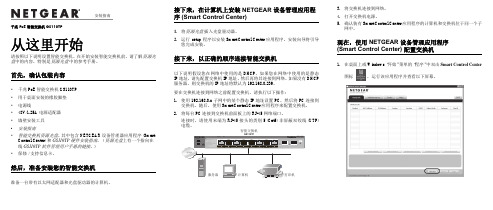
®NS-104UT-MAQ, NS-508UT-GAQ Unmanaged PoE SwitchesManualFeatures:•Provides both Ethernet data and power to multiple PoE devices including IP cameras, IP access, IP speakers/intercoms, VOIP, etc. •Specially designed for video transmissionwith fast packet forwarding capability for clear images and smooth transmission •Easy plug-and-play installation •Supports 10,100BaseT (NS-508UT-GAQ supports up to 1000BaseT Gigabit) •Conforms to IEEE 802.3, IEEE 802.3u,IEEE 802.3af, IEEE 802.3at (NS-508UT-GAQ also conforms to IEEE 802.3ab) •IEEE 802.3x Flow controlModel Ethernet Ports Bandwidth VLAN Power NS-104UT-MAQ 10/100Base-TX 4 Downlink, 2 uplink 1.2Gbps Yes 60W Adapter NS-508UT-GAQ 10/100/1000Base-TX 8 Downlink, 2 uplink 20Gbps No 120W Built-inNS-508UT-GAQ shownENFORCER Unmanaged PoE SwitchesENFORCER Unmanaged PoE Switches provide Ethernet and power to PoE devices such as IP cameras, IP access control, IP speakers/intercoms, IP telephony, etc. Fast packet forwarding capability and extra backplane bandwidth ensure clear images at fast transmission speeds for video, making them well-suited for HD CCTV installations.1x PoE Switch 1x AC Power cord1x Power adapter* 1x Manual*NS-104UT-MAQ onlyModel NS-104UT-MAQ NS-508UT-GAQ Operating voltage 48~57 VDC* 100~240 VACPower consumption <5W <15WPorts 4 Downlink, 2 uplink 8 Downlink, 2 uplink Ethernet speed 10/100Mbps (uplink, 100Mbps) 10/100/1000Mbps (uplink, 1000Mbps) Ethernet standardIEEE 802.3, IEEE 802.3u,IEEE 802.3af, IEEE 802.3atIEEE 802.3, IEEE 802.3u,IEEE 802.3af, IEEE 802.3at,IEEE 802.3x, IEEE 802.3ab Transmission distance 328ft (100m)†‡328ft (100m)†PoE Capacity 55W 120WSwitching capacity 1.2Gbps 20GbpsTransferrate10Mbps 14,880pps100Mbps 148,800pps1000Mbps N/A 1,488,000ppsMAC Address table 1K 4kLED Indicators Connection/transmission and PoE for each port, power Operating humidity 0~85% Non-condensing 0~85% Non-condensing Operating temperature -40°~158° F (-40°~70° C) -40°~158° F (-40°~70° C) Dimensions 4"x7/8"x215/16" (102x22x75 mm) 77/8"x23/4"x45/8" (200x44x118 mm) Weight 6.8-oz (194g) 1-lb 12.4-oz (806g) Specifications:Introduction:Parts List:*Power adapter included†Distance depends on Ethernet cables used. Cat5e/6 recommended.‡656ft (200m) at 10Mbps with VLAN switch ONENFORCER Unmanaged PoE SwitchesSECO-LARM U.S.A., Inc.3Sample Installation:NS-508UT-GAQ Overview:77/8" (200mm)45/8" (118mm)Power LED8 Downlink ports2 Uplink ports100~240 VAC Power input (on back panel)13/4"(44mm)PoE LED Link/Active LED**Flashing green when data is being transmittedSample CCTV Application:1. Determine the best location for the switch. Note that the uplink cable (as well as the PoEdevice cable, except for the NS-104UT-MAQ with the VLAN function switch turned ON) cannot exceed 328ft (100m).2. If installing the NS-104UT-MAQ, make sure that the VLAN function switch is set correctly.3. Turn off power to both the display device and the PoE device before proceeding. Installation under power will damage the transmission equipment.4. Connect the PoE device(s) to a downlink port on the switch using a Cat5e/6 cable conforming to either the EIA/TIA 568A or 568B standard.5. Connect the DVR or computer to the uplink port on the switch using a Cat5e/6 cable conforming to either the EIA/TIA568A or 568B standard.6. Connect the power to the switch and ensure that the power LED and the POE led on any connected port is on.7. Turn on the display device and ensure that the system is functioning properly.PoE Cameras or other PoE devicesHD MonitorDVRPower adapterPoE Switch(NS-104UT-MAQ shown)ENFORCER Unmanaged PoE Switches 4 SECO-LARM U.S.A., Inc.PoE Device doesn't function correctly• Confirm that both input and output devices are turned on•Ensure that the Ethernet cable does not exceed 328ft (100m) or 656ft (200m) for NS-104UT-MAQ with VLAN function switch turned ON • Confirm that no PoE equipment power requirement exceeds 30W • Confirm that the Ethernet cable meets EIA/TIA 568A or 568B standard and that both ends are the same standard (not a crossover cable) • Test that the Ethernet cable to ensure that it is operational• Test with another PoE device that is known to be operating correctlyTroubleshooting:SECO-LARM® U.S.A., Inc.16842 Millikan Avenue, Irvine, CA 92606 Website: Phone: (949) 261-2999 | (800) 662-0800 Email:*******************PICSN7MI_NS-x0xUT-xAQ_200611.docxNOTICE: The SECO-LARM policy is one of continual development and improvement. For that reason, SECO-LARM reserves the right to change specifications without notice. SECO-LARM is also not responsible for misprints. All trademarks are the property of SECO-LARM U.S.A., Inc. or their respective owners. Copyright © 2020 SECO-LARM U.S.A., Inc. All rights reserved.WARRANTY: This SECO-LARM product is warranted against defects in material and workmanship while used in normal service for one (1) year from the date of sale to the original customer. SECO-LARM’s obligation is limited to the repair or replacement of any defective part if the unit is returned, transportation prepaid, to SECO-LARM. This Warranty is void if damage is caused by or attributed to acts of God, physical or electrical misuse or abuse, neglect, repair or alteration, improper or abnormal usage, or faulty installation, or if for any other reason SECO-LARM determines that such equipment is not operating properly as a result of causes other than defects in material and workmanship. The sole obligation of SECO-LARM and the purchaser’s exclusive remedy, shall be limited to the replacement or repair only, at SECO-LARM’s option. In no event shall SECO-LARM be liable for any special, collateral, incidental, or consequential personal or property damage of any kind to the purchaser or anyone else.IMPORTANT: Users and installers of this product are responsible for ensuring this product complies with all national, state, and local laws and statutes related to monitoring and recording audio and video signals. SECO-LARM will not be held responsible for the use of this product in violation of any current laws or statutes. FCC COMPLIANCE STATEMENTTHIS DEVICE COMPLIES WITH PART 15 OF THE FCC RULES. OPERATION IS SUBJECT TO THE FOLLOWING TWO CONDITIONS: (1) THIS DEVICE MAY NOT CAUSE HARMFUL INTERFERENCE AND (2) THIS DEVICE MUST ACCEPT ANY INTERFERENCE RECEIVED, INCLUDING INTERFERENCE THAT MAY CAUSE UNDESIRED OPERATION.Notice: The changes or modifications not expressly approved by the party responsible for compliance could void the user’s authority to operate the equipment.IMPORTANT NOTE: To comply with the FCC RF exposure compliance requirements, no change to the antenna or the device is permitted. Any change to the antenna or the device could result in the device exceeding the RF exposure requirements and void user’s authority to operate the device.。
千兆PoE智能交换机GS110TP说明文档说明书
千兆 PoE 智能交换机 GS110TP从这里开始请按照以下说明设置智能交换机。
在开始安装智能交换机前,请了解资源光盘中的内容,特别是资源光盘中的参考手册。
首先,确认包装内容•千兆 PoE 智能交换机 GS110TP•用于桌面安装的橡胶脚垫•电源线•48V/1.25A 电源适配器•墙壁安装工具•安装指南•智能交换机资源光盘,其中包含 NETGEAR 设备管理器应用程序 (Smart Control Center) 和GS110TP 硬件安装指南。
(资源光盘上有一个指向在线GS110TP软件管理用户手册的链接。
)•保修/支持信息卡。
然后,准备安装您的智能交换机准备一台带有以太网适配器和光盘驱动器的计算机。
接下来,在计算机上安装 NETGEAR 设备管理应用程序 (Smart Control Center)1.将资源光盘插入光盘驱动器。
2.运行setup程序以安装 Smart Control Center 应用程序。
安装向导将引导您完成安装。
接下来,以正确的顺序连接智能交换机以下说明假设您在网络中使用的是 DHCP。
如果您在网络中使用的是静态IP 地址,请先配置交换机 IP 地址,然后再将其连接到网络。
如果没有 DHCP服务器,则交换机的 IP 地址将默认为 192.168.0.239。
要在交换机连接到网络之前配置交换机,请执行以下操作:1.使用 192.168.0.x 子网中的某个静态 IP 地址设置 PC,然后将 PC 连接到交换机。
随后,使用 Smart Control Center 应用程序来配置交换机。
2.将每台 PC 连接到交换机前面板上的 RJ-45 网络端口。
连接时,请使用末端为 RJ-45 接头的类别 5 (Cat5) 非屏蔽双绞线 (UTP)3.将交换机连接到网络。
4.打开交换机电源。
5.确认装有 Smart Control Center 应用程序的计算机和交换机位于同一个子网中。
poe交换机技术标准

poe交换机技术标准
Poe交换机技术标准是指为了保障Poe交换机的正常运行,规范Poe交换机的设计、制造、安装、使用和维护等方面的标准。
以下是Poe交换机技术标准的主要内容:
1. 设计标准:Poe交换机的设计应符合国家相关标准和行业标准,采用合理的电路设计、电子元件和材料,保证产品的质量和稳定性。
2. 制造标准:Poe交换机的制造应符合国家相关标准和行业标准,采用优质的材料和先进的制造工艺,保证产品的可靠性和耐用性。
3. 安装标准:Poe交换机的安装应符合国家相关标准和行业标准,采用恰当的安装方法、位置、环境和电源等,保证设备的安全可靠和正常运行。
4. 使用标准:Poe交换机的使用应符合国家相关标准和行业标准,采用合理的操作方法和使用环境,保证设备的正常运行和性能发挥。
5. 维护标准:Poe交换机的维护应符合国家相关标准和行业标准,采用及时、有效的维护方法和措施,保证设备的正常维护和保养,延长设备的使用寿命。
总之,Poe交换机技术标准是为了规范Poe交换机的生产、使用和维护,保障设备的正常运行和使用效果,对于保障网络稳定运行和提高网络安全性具有重要意义。
- 1 -。
- 1、下载文档前请自行甄别文档内容的完整性,平台不提供额外的编辑、内容补充、找答案等附加服务。
- 2、"仅部分预览"的文档,不可在线预览部分如存在完整性等问题,可反馈申请退款(可完整预览的文档不适用该条件!)。
- 3、如文档侵犯您的权益,请联系客服反馈,我们会尽快为您处理(人工客服工作时间:9:00-18:30)。
POE以太网交换机技术规范书中国联通河北省分公司二零零九年十一月一、总则1.概述1.1 本文件为中国联合通信有限公司(以下简称买方)对POE以太网交换机设备招标采购中的设备供应商(以下简称卖方)提出的技术规范书。
本规范书将作为谈判的基础。
1.2 卖方所提供的所有各项设备和系统(包括软、硬件)应符合技术标准的要求如下:(1) 符合有关标准(如ISO、ITU-T、ETSI、IETF等),卖方应在建议书中具体说明,并附上相应的详细技术资料;(2) 若卖方的设备和系统包含自己的专用标准,应在建议书中具体说明,并附上相应的详细技术资料;(3) 本文件中未给出,但ITU-T已有建议的系统设备性能和功能均应满足ITU-T 最新建议要求;(4) 待买方新的标准(中华人民共和国通信行业标准和中国联合通信有限公司相关技术要求等)制定出来后,卖方应免费修改其系统以满足要求。
(5) 中华人民共和国通信行业标准YD/T-1255-2003《具有路由功能的以太网交换机技术要求》,及其它已颁发的相关技术要求和文件,具备中国信息产业部颁发的电信设备进网许可证;(6) 国家已颁发的相关法律文件(例如招标法等)。
1.3 卖方应按照本文件的要求提供报价和详细的技术建议。
卖方提供的各项设备及系统的功能、性能应完全符合买方指明的标准,并满足或高于买方指出的要求。
对于本文件未规定的有关设备性能,卖方应提出建议,并陈述其理由。
1.4卖方应根据本文件的要求提供建议书,建议书要求采用中文书写,设备技术资料应尽量提供中文,可提供英文。
1.5规范书有关内容的澄清(1) 卖方对于规范书的疑问可以通过书面材料与买方联系。
在规定的建议书最后提交期限以前,买方将以书面材料给予答复。
有关买方答复材料的复印件也将递交所2中国联通POE交换机集中采购技术规范书有得到技术规范书的卖方。
(2) 在技术谈判的各个阶段,买方将以书面形式要求卖方对有关问题进行进一步的技术澄清,卖方应以书面资料给予正式应答;所有各阶段的技术澄清文件都将作为合同附件。
1.6 买方在任何时候保留和拥有对本文件的解释权。
买方有权在签订合同前,根据需要修改和补充本技术规范书,修改补充后的最终技术规范书将作为合同的附件。
2.卖方的技术应答要求2.1技术规范书点对点应答要求要求对本规范书所提出各项要求进行逐条逐项答复、说明和解释。
首先对实现或满足程度明确做出“满足”、“不满足”等应答(不允许出现“部分满足的字样”),答复“满足”的情况下,默认所有的条款均支持或满足;答复“不满足”的情况下,需要对不满足的部分做出具体、详细的说明。
二、POE以太网交换机技术要求本次采购的以太网交换机为POE以太网交换机。
卖方应在技术应答中按设备具体型号给出以下性能指标的详细数据。
1.POE以太网交换机1.1POE交换机性能要求类型I:要求整机不少于24个下行POE端口,上行千兆光口不少于1个,交换容量不小于8.8Gbps,包转发能力不小于6.55Mpps。
类型II:要求整机不小于16个下行POE端口,上行千兆光口不少于1个,交换容量不小于7.2Gbps,包转发能力不小于5.36Mpps。
类型III:要求整机不小于8个下行POE端口,交换容量不小于3.6Gbps,包转发能力不小于2.68Mpps。
1.2卖方提供的以太网交换机设备丢包率和时延性能须满足:3(1)64字节包,时延≤100μs;(2)丢包率:二层丢包率:01.3卖方提供的POE以太网交换机设备的可靠性指标须达到:(1)系统必须达到或超过99.999%的可用性(2)无故障连续工作时间系统的无故障工作时间: MTBF≥30万小时。
(3)故障恢复时间系统故障恢复时间≤120 mins。
1.4卖方提供的设备应能在下列供电变化范围内正常工作:(1)直流电压及其波动范围要求:额定电压: 为-48V的直流电源。
电压波动范围:在直流输入端子处测量-48V电压允许变动范围为-57~- 40V。
交换机在此范围内应工作正常。
(2)交流电压及其波动范围要求单相220V±10%,频率50Hz±5%。
线电压波形畸变率小于5%。
1.5环境要求硬件设备要在下列环境下能够保证正常工作:(1)长期工作条件:温度保持15~30℃、相对湿度保持40%~65%(2)短期工作条件:温度保持0~40℃、相对湿度保持20%~90%注:交换机的正常工作的温度和相对湿度的测量点指在地板以上2m和交换机前方0.4m处测量值。
短期工作条件是指连续不超过48小时和每年累计不超过15天。
相对湿度低于20%的环境应采用抗静电地面。
(3)防雷能力:POE机型的设备需要支持AC电源口的至少4kV防雷能力,数据业务接口需要支持至少1kV的防雷能力;1.6 POE能力要求4中国联通POE交换机集中采购技术规范书硬件设备必须符合以下标准:(1) IEEE 802.3af标准,实现15.4W的POE供电能力;可以为基于IP的终端(如IP电话机、无线局域网接入点AP、网络摄像机等)传输数据信号的同时,还能为此类设备提供直流供电的技术。
(2) 整个设备的电源能力需要能够支持所有端口均同时支持POE能力;1.7 设备功能要求1)支持IEEE 802.3和ETHERNET II帧封装形式,并支持以存储转发模式完成数据包的交换转发。
2)支持全双工/半双工模式及端口速率可配,并支持设备间端口工作模式的自协商(AUTO-NEGATIATION)。
3)支持MAC地址的手工配置和动态学习功能。
4)具备异常帧检测功能,可识别并过滤超短帧、CRC校验错帧等各种异常帧,同时保证正常帧的转发。
5)支持超长帧的转发(最大转发帧长不小于1536BYTE)。
6)投标人应逐条说明是否支持以上交换功能,并说明设备FE和GE端口可转发的最大帧长。
7)支持生成树协议:IEEE规定的生成树协议有以下三种:-标准生成树(STP),IEEE 802.1D-快速生成树(RSTP),IEEE 802.1W-多生成树(MSTP),IEEE 802.1S要求在简单拓扑环境下(网络层次不大于2层)标准生成树协议的链路收敛时间不大于45秒,快速生成树协议的链路收敛时间不大于200毫秒。
设备必须支持基于物理端口打开或关闭生成树协议功能。
投标人需说明设备对三种生成树协议的支持情况,收敛时间是否符合要求,并提供可配置的协议参数,如节点权值、端口权值等,并提供设备与其他主流厂家设备各种生成树协议的互通情况。
8)要求设备必须支持基于物理端口划分VLAN,并采用IEEE 802.1Q封装形式,各FE和GE端口支持tagged和untagged两种工作方式,其中tagged端口可配置允许通过VLAN范围,并支持VLAN PRUNING。
投标人需说明设备对以上VLAN功能的支5持情况,以及是否可通过其他方式划分VLAN,如MAC地址、上层协议。
9)设备必须支持通过配置来启用或禁用指定的VLAN。
投标人应提供设备可配置的VLAN范围,如有厂家保留VLAN,必须特别说明。
10)设备要求支持上下行端口的N:1的VLAN聚合功能,即下行端口VLAN ID不同,设备将多个VLAN聚合为一个VLAN ID上行。
实现VLAN聚合功能后不能影响设备数据包上下行的正确转发。
11)设备需要支持DHCP OPTION 82功能,可将物理端口信息、用户VLAN信息、设备信息插入DHCP Discovery消息中,传给上层网络设备。
建议设备信息能够用IP地址、MAC地址、字符串等形式表现,做到可配置、可修改。
12)要求交换机设备的FE和GE端口必须支持访问控制功能,可匹配的字段包括:-源MAC地址、目的MAC地址;-标准VLAN环境中的VLAN ID和802.1P优先级字段;-Ethernet Type字段-源IP地址、目的IP地址、IP TOS;-四层协议类型及源、目的端口号。
建议交换机支持基于VLAN端口的访问控制(在VLAN端口下,根据MAC、IP地址等进行访问控制);建议交换机同时支持出、入方向的访问控制。
同时支持入方向和出方向的速率限制。
建议设备可对超过限制要求的流量选择不同处理方式,如允许转发、丢弃、修改优先级等13)要求设备具备对指定端口及VLAN下的MAC地址数量进行限制的功能。
交换机支持端口与用户MAC地址绑定的功能,能够阻止指定源MAC地址的流量。
设备必须支持VLAN隔离功能,可以隔离属于同一VLAN的物理端口间的互访。
设备要求在遭受各种网络攻击( ARP、ICMP、BPDU等)时,能够提供自我保护功能,同时不影响正常业务的转发14)建议设备提供WEB配置管理界面,客户端可通过浏览器对设备进行配置。
1.8 性能指标:1)交换机MAC地址容量不小于4K。
2)交换机FE及GE端口的MAC地址学习速度大于100个/秒。
3)投标人需提供交换机各种端口(包括FE、GE)在不同帧长(64、65、127、128、6中国联通POE交换机集中采购技术规范书256、512、1024、1518)下的转发性能数据。
4)交换机整机访问控制列表至少200条。
7。