产品附件 德力西电气CDM3塑壳断路器产品样本
德力西电气 CDM6EY样本2023第一版 产品说明书

CDM6EY 电子式液晶塑壳断路器
121
■ 保护特性
122
■
产品功能表
说明:符号“●”表示有其功能;符号“○”表示此功能可选择。
123
海拔(m )200025003000400045005000工频耐压(V )250025002250195017751625绝缘耐压(V )10001000900780710650最大工作电压(V )400400350312284260工作电流修正系数
1
1
0.98
0.95
0.92
0.9
■ 海拔高度降容
当温度超过40℃时,过载保护会发生很小的变化,脱扣时间/电流曲线中,断路器In
整定值必须按照以下系数进行修正。
■ 温度影响特性
高度在2000米以下不会对断路器性能有影响。
超过这个高度,必须考虑空气绝缘特性和冷却能力的下降因素;下表给出的修正系数用于安装海拔超过2000米的情况。
124
■ 接线排及扭矩表
■ 核心物料订货号。
德力西电气 新DZ20塑壳断路器样本 产品说明书

DZ20系列塑料外壳式断路器(以下简称断路器),其额定绝缘电压为 800V 、交流 50Hz 、额定工作电压400V 及以下,其额定电流从16A 至800A 。
在正常情况下,断路器可分别作为线路不频繁转换及电动机的不频繁起动之用。
配电用断路器在配电网络中用来分配电能,且可作为线路及电源设备的过载、短路保护。
保护电动机用断路器在配电网络中用作鼠笼型电动机的起动和运转中分断以及作为电动机的过载、短路保护。
本系列派生的透明外壳剩余电流动作断路器,盖子采用进口的新型、耐高温、高强度材料制造而成,断点清晰可见。
该系列广泛应用于建筑工地临时用电场所。
■ 产品简介产品符合标准:GB/T 14048.1 总则 IEC 60947-1 总则GB/T 14048.2 断路器 IEC 60947-2 断路器■ 符合标准正常工作海拔:≤2000m 如需要安装在海拔超过2000m 的情况下,必须考虑到介电强度的改变和空气温度下降的因素,可参考海拔高度降容系数表使用,或请联系我们。
■ 海拔正常工作条件:-5~40℃对于-40℃ ~-5℃,40℃~70℃的场合,请联系我们。
工作环境温度超过40℃,应参考温度降容系数表使用;存储温度:储藏温度:-40~70℃(如储藏温度低于正常工作条件,应将产品恢复至工作条件温度下静置至少24小时后投入使用)■ 环境温度正常工作湿度:在周围空气湿度为+40℃的条件下,大气相对湿度不能超过50%;如果温度较低,则可以在较高的相对湿度条件下使用;例如:+20℃时,达90%。
对于由于温度变化偶尔产生的凝露应采取特殊措施;具有隔离功能的可靠触头指示符合IEC 标准GB/T 14048.2中所定义的隔离隔离位置对应于O (OFF )位置只有触头真正打开,操作手柄才能指示"OFF"位置旋转手柄或电操机构不会改变触头指示系统的可靠性■ 湿度注:1.除欠压外电气附件接线形式默认为引线0.5m ,可选引线1m 或者端子,欠压接线形式仅有端子。
德力西电气 CDMNE塑料外壳式断路器样本 产品说明书

CDMNE 系列塑料外壳式断路器,适用于额定工作电压AC690/800/1000/1140V ,额定电流63~630A 的交流线路中,可广泛应用于光伏发电行业的交流汇流箱、汇流柜;电力行业并网柜等场合中。
用来分配电能,保护线路和电源设备,使免受过载,短路等故障的危害。
注:1.欠压脱扣器、手操、电操仅250AF 有 2.250/400/630A F 的内部附件仅组合卖,不支持单卖 3.DC24V 分励仅250AF 有 4.如需应用于风电行业或AC1000/1140V 系统中,请特殊备注或优先联系德力西销售CDMNE-250CDMNE-320CDMNE-400/630产品选型CDMNE 塑料外壳式断路器产品概述CDMNE 塑料外壳式断路器基本介绍壳架等级:250A 、320A 、400A 、630A额定电流:63~630A额定电压:AC690V ,AC800V ,AC1000V ,AC1140V额定绝缘电压:1140V 、1250V额定冲击耐受电压:8kV 、12kV隔离功能:有认证:CCC 、CE防护等级:IP30污染等级:3级基本参数海拔:≤2000m环境温度:-40℃~+70℃环境温度+40℃时相对湿度不超过50%,较低温度可以有较高湿度,如:25℃时相对湿度可达80%,对于因温度变化所产生的凝霜应采取相应的措施(注:在-40℃~-5℃、+40℃~+70℃范围内的使用,请参考温度降容系数表)储存环境:周围温度-40~+70℃,相应湿度25℃≤80%工作环境• GB14048.1 低压开关设备和控制设备第1部分:总则• GB14048.2 低压开关设备和控制设备第2部分:断路器• IEC 60947-1 Low-voltage switchgear and controlgear-Part 1:General Rules• IEC 60947-2 Low-voltage switchgear and controlgear-Part 2:Circuit-breakers 符合标准产品参数CDMNE 塑料外壳式断路器降容表说明周围温度不在+40℃时,需要校验时的额定电流进行温度补偿修正值高度在2000米以下不会对断路器性能有影响。
德力西电气 CDM3E产品样本 产品说明书

191190备注:1)1250A 和1600A 无通信功能2)1250A 和1600A 无过载报警功能3)1250A 和1600A 的分励和电操无AC110V 、DC110V 、DC220V 控制电压4)800 壳架及以下内部附件(除欠压为端子式供货)其它产品标配为引线供货长度500mm ;如有其它长度或带端子需求请备注;5)125AF 、250AF 无抽出式产品。
400AF 、630AF 无插入式板前产品6)插入式板前产品默认配置水平出线排7)常规产品标配: 相间隔弧板、安装螺钉8)三遥标配(辅报+通信模块);四遥标配(辅报+电操+通信模块)。
通信模块电压为AC230V /400V C D M 3EGB/T 14048.1 总则IEC 60947-1 总则GB/T14048.2 断路器IEC 60947-2 断路器■ 符合的标准CDM3E 系列产品运行在污染等级为3级IEC 60947-1和60664-1标准所定义的环境(工业环境)中根据GB/T14048.1-2012 表H.1的内容:在海拔2000m 处额定冲击耐受电压8kV 时■ 污染等级周围空气温度上限为+70℃,下限为-40℃;24h 平均温度不超过35℃(注:在-40℃~-25℃、+40℃~+70℃范围内使用,请与制造商联系或参 见降容系数表)存储温度为-40℃至70℃■ 环境温度正常工作安装地点的海拔不超过2000m如需要安装在海拔超过2000m 的情况下,必须考虑到介电强度的改变和空气温度下降的因素,可参考海拔高度降容系数表使用,或请联系我们■ 海拔正常工作时需满足:在周围空气温度为+40℃的条件下,大气相对湿度不能超过50%,如果温度较低,则可以在较高的相对湿度条件下使用。
最湿月份的月平均相对湿度为90%。
需要考虑产品表面产生的凝露对产品性能的影响。
■ 湿度CDM3E 系列塑壳断路器都符合IEC 标准60947-2中所定义的隔离隔离位置对应于O (OFF )位置只有触头真正打开,操作手柄才能指示“OFF ”位置旋转手柄或电操机构不会改变触头指示系统的可靠性■ 具有隔离功能的可靠触头指示断路器本体:IP20(不含接线端子)安装在开关柜中的断路器:带有转动手操的断路器:IP40带有电操机构的断路器:IP40■ 防护等级干冷、干热、湿热■ 抗湿热能力1931922)生产为板后水平接线,用户可自行改装为板后垂直接线,参见抽出式板后接线安装图195194注:I R 最大设定值不可超过Inm确保用户长期在高温下使用,不因过高的温升导致故障的发生,推荐用户参考此温度降容系数表。
德力西电气 CDM6ZB直流塑壳断路器样本-2023年第一版 产品说明书

基本介绍基本参数铭牌解释符合标准外形及安装尺寸固定板前安装孔图端子板安装孔图 面板开孔尺寸 标准本体选型说明可选附件型号解释壳架电流对应表脱扣特性曲线 维护与保养 安全告知 核心物料订货号主要技术参数适用环境降容表说明接线方式接线图附件安装对照表附件参数及功能0201■ CDM6ZB-125H 63A 2P 30msCDM6ZB 直流塑壳断路器,适用于额定工作电压DC125V ,DC250V ,额定电流63A ~800A 的直流电路中,可广泛应用于光伏发电、充电桩、发电厂、电力电源、轨道交通、通讯等直流环境,用来分配电能,保护线路和电源设备,使免受过载、短路等故障的危害。
该系列产品均具备短路短延时功能。
可全面提升电能的分配与管理效率。
■ 基本介绍■ 符合标准GB/T 14048.1 低压开关设备和控制设备第1部分:总则GB/T 14048.2 低压开关设备和控制设备第2部分:断路器IEC 60947-1 Low Voltage Switchgear and Controlgear-Part 1:General RulesIEC 60947-2 Low Voltage Switchgear and Controlgear-Part 2:Circuit-breakers■ 适用环境工作温度:-5℃~40℃储存温度:-40℃~70℃海拔高度:≤2000米污染等级:3级防护等级:IP20抗湿热能力:干冷、干热、湿热单卖附件型号解释备注: 1、拓展端子,也叫附件板,或者接线铜排 2、分励/辅助/报警有分带端子与带引线两种类型 3、分励/欠压电压类型:DC24V 、DC110V (定制)、DC220V (定制)、AC230V 、AC400V 4、所有内部附件仅支持左侧安装■ 单卖附件选型04030605周围温度不在+40℃时,需要校验时的额定电流进行温度补偿修正值温度补偿修正系数表高度在2000米以下不会对断路器性能有影响。
德力西电气 CDM6SPV 光伏专用塑料外壳式断路器 产品说明书
标准本体选型说明 可选附件型号解释 壳架电流对应表外形及安装尺寸 固定板前安装孔图 固定板后安装孔图 插入式板前/后安装孔图 端子板安装孔图脱扣特性曲线 维护与保养安全告知核心物料订货号基本介绍基本参数使用环境符合标准铭牌解释主要技术参数 降容表说明 附件参数及功能 附件安装对照表目录/ CONTENT基本介绍CDM6SPV光伏专用系列塑料外壳式断路器,适用于额定工作电压AC480V、AC500V、AC690V,额定电流63A~630A的交流电路中,可广泛应用于光伏发电,汇流箱等,用来分配电能,保护线路和电源设备,使免受过载,短路等故障的危害。
基本参数壳架等级:125A、250A、400A、630A额定电流:63A~630A额定电压:AC480V、AC500V、AC690V额定绝缘电压:AC800V隔离功能:有额定冲击耐受电压:8KV认证:CCC使用环境温度:• 正常工作温度:-5℃~40℃,24小时内平均温度不能超过+35℃。
• 环境温度:-40℃~70℃• 如产品工作环境温度超过40℃,应参考温度降容系数表使用,或请联系我们。
湿度:正常工作时需满足:• 在周围空气温度为+40℃的条件下,大气相对湿度不能超过50%,如果温度较低,则可以在较高的相对湿度条件下使用。
• 最湿月份的月平均相对湿度为90%。
• 需要考虑产品表面产生的凝露对产品性能的影响。
海拔:• 正常工作安装地点的海拔不超过2000m• 如需要安装在海拔超过2000m的情况下,应参考海拔降容系数表使用,或请联系我们。
抗湿热能力:• 干冷、干热、湿热防护等级• 本产品的防护等级为:IP20• 本产品污染等级为:3级符合标准• GB14048.1 低压开关设备和控制设备第1部分:总则• GB14048.2 低压开关设备和控制设备第2部分:断路器• IEC 60947-1 Low-voltage switchgear and controlgear-Part 1:General Rules• IEC 60947-2 Low-voltage switchgear and controlgear-Part 2:Circuit-breakers产品概述概述产品概述铭牌介绍产品描述额定电流产品认证基准温度隔离符号符合标准分断能力瞬时脱扣电流li频率Fre.绝缘电压Ui冲击耐受电压Uimp技术参数技术参数技术参数海拔降容系数周围温度不在+40℃时,需要校验时的额定电流进行温度补偿修正值 温度补偿修正系数表冲击耐受电压Uimp (kV )877 6.5 6.566最大工作电压Ue (V )69069069066060060055040℃环境下热额定值In (A )1In0.98In0.94In0.92In0.88In0.86In0.85In高度在2000米以下不会对断路器性能有影响。
德力西电气 CDMQ1水泵缺相保护断路器样本 产品说明书
CDMQ1水泵缺相保护器产品样本北京办事处北区中区地址:北京市丰台区枫竹苑一区(未来假日花园)18-10 邮编:100076天津办公点地址:天津市西青区凯安道凯信佳园9-3-401邮编:300100沈阳办公点地址:辽宁省沈阳市于洪区细河南路碧桂园银河城钻石郡148-3邮编:110000长沙办公点地址:湖南长沙市芙蓉区万象企业公馆5栋2709邮编:410000郑州办公点地址:河南郑州金水区青年路145号6号楼17层1706号邮编:450000武汉办公点地址:湖北武汉市江汉区新华路186号福星国际商会大厦2516、2517室邮编:430000温州办公点地址:浙江省乐清市柳市镇德力西工业园邮编:325604成都办公点地址:成都市金牛区人民北路二段118号金牛万达广场甲级C座 16楼1603号邮编:610000南京办公点地址:江苏省南京市秦淮区洪武路23号隆盛大厦1505、1506室邮编:210000重庆办公点地址:重庆市九龙坡区渝洲路4号18-9号邮编:400039广州办事处地址:广州市荔湾区南岸路63号城启大厦1905室 邮编:510160南宁办公点地址:南宁市西乡塘区北大路中梦泽园小区岳阳阁5单元202室邮编:530003昆明办公点地址:昆明市西山区棕树营街道办事处土堆村碧鸡名城C地块9幢2802室邮编:650000贵阳办公点地址:贵阳市观山湖区石林东路中天帝景传说B区B4栋1单元1302室西安办事处地址:陕西西安市莲湖区大庆路三号蔚蓝国际A705 邮编:710082新疆办公点地址:新疆乌鲁木齐市米东区米东南路红光雅居D区6号楼3单元602室邮编:830000青岛办公点地址:青岛市城阳区正阳路177号15号楼2单元903室邮编:214000福建办公点地址:福州市晋安区东二环泰禾广场7号楼1117单元邮编:350024济南办公点地址:山东省济南市历下区工业南路55号未来城商务中心13#楼608室邮编:250000杭州办公点地址:杭州市江干区蓝桥景苑11幢2单元1002室邮编:310016南昌办公点地址:江西南昌市西湖区广场东路恒茂国际华城23幢2907邮编:330002深圳办公点地址:深圳市龙华新区民丰路1号碧水龙庭7栋4单元14D 邮编:518109兰州办公点地址:兰州市城关区瑞德摩尔万国港E座2208邮编:730020电话:153****1522合肥办公点地址:安徽省合肥市瑶海区武里山路五里山天街3A-1402室邮编:230000吉林办公点地址:吉林省长春市经开区浦东路与深圳街交汇处虹湾国际A座706室邮编:130031黑龙江办公点地址:黑龙江省哈尔滨市道外区润达国际D座2单807室邮编:150050石家庄办公点地址:石家庄市裕华区华兴生活小区41-1-102邮编:050011太原办公点地址:山西太原市万柏林区西矿街70号红星小区五单元1402邮编:030024石家庄物流地址:河北省石家庄市元氏县殷村石武铁路东国达物流园内电话:155****1257辽宁物流地址:沈阳市苏家屯区雪莲街188号(雪莲街与四环路交叉口)华翔东北亚贸城 D1 德力西陕西物流地址:陕西省西安市六村堡丰产路西段陕西商储物流园南区B1号德力西仓库山东物流地址:山东省临沂市经济技术开发区翔宇路23号华派克物流园内 重庆物流地址:重庆市江津区珞璜工业园B区重庆西部诚通物流有限公司5号库成都物流地址:四川省成都市青白江区国际集装箱物流园区德汇路9号4栋4-4号广东物流地址:广东省佛山市南海区里水镇怡和二路银裕木业制品厂直入100米河南物流地址:河南省郑州市经济开发区国际物流园喜达路宇培物流园(礼通路)东北W4-A区4B 58-59号湖北物流地址:湖北省武汉市东西湖区临空港大道23号捷利物流园3号库温州物流地址:浙江省乐清市柳市镇德力西高科技生态工业园新疆物流地址:乌鲁木齐市友谊路230号(新疆诚通国际物流园内德力西仓库)芜湖物流地址:安徽省芜湖市芜湖县新芜经济开发区朝阳路德力西物流中心适用范围结构与工作原理缺相保护器壳架电流或适用电机功率运行接线图示例适用环境■ 海拔高度不超过2000米■ 周围空气温度:●周围空气温度上限不超过+40℃;●周围空气温度24h 的平均值不超过+35℃;●周围空气温度下限不低于-5℃;■ 大气条件:大气的相对湿度,在周围最高温度+40℃时不超过50%,在较低温度下可以有较高的相对湿度, 在最湿月的月平均最低温度不超过+25℃时,该月月平均最大相对湿度为不超过90%,并考虑温度变化发生 在产品表面上的凝露。
德力西电气 CDM6Ei样本 电子式塑壳断路器 说明书

高参数指标,满足特定行业的应用需求,适应更加严苛的应用场合。
H型分断能力Icu=85KA Ics=65KA M型分断能力Ics=100% Icu=50KA断路器本体腔室内能装更多附件, 可单独购买通讯背包实现更多的附件拓展功能。
通讯背包即插即用,减少库存,可单独购买通讯背包,实现功能升级。
(四遥:遥控,遥调,遥测,遥信)电流覆盖范围更广覆盖125/250/400/630/800壳架,具1600A壳架,壳架小型化,可替代部分馈线侧框架应用,给客户带来更高的性价比。
可现场查看故障记录,开关状态,快速确定故障原因,减少宕机时间。
APP可验证电子脱扣可靠性、获得在线技术支持,给客户带来更加高效的服务体验。
断路器具备报警不脱扣功能,满足消防设备的特殊需求,全面覆盖行业的所有应用要求。
断路器更好的环境温度适应性,使用更省心。
扫描二维码下载app完全满足Ics=100% Icu=50KA招标需求报警不脱扣功能 精准保护096095GB/T 14048.1 总则 IEC 60947-1 总则GB/T 14048.2 断路器IEC 60947-2 断路器■ 符合的标准CDM6Ei 系列产品运行在污染等级为3级IEC 60947-1和IEC 60664-1标准所定义的环境(工业环境)中■ 污染等级正常工作时需满足:在周围空气温度为+40℃的条件下,大气相对湿度不能超过50%, 如果温度较低,则可以在较高的相对湿度条件下使用。
最湿月份的月平均相对湿度为90%。
需要考虑产品表面产生的凝露对产品性能的影响。
■ 湿度CDM6Ei 系列塑壳断路器都符合IEC60947-2中所定义的隔离隔离位置对应于O (OFF )位置只有触头真正打开,操作手柄才能指示“OFF ”位置旋转手柄或电操机构不会改变触头指示系统的可靠性经过测试,隔离功能安全可靠■ 具有隔离功能的可靠触头指示周围空气温度上限为+70℃,下限为-40℃;24h 平均温度不超过35℃ (注:在-40℃~-25℃、+40℃~+70℃范围内使用,请与制造商联系或参 见降容系数表)存储温度为-40℃至70℃■ 环境温度断路器本体:IP20(不含接线端子)安装在开关柜中的断路器:带有转动手操的断路器:IP40带有电操机构的断路器:IP40■ 防护等级干冷、干热、湿热正常工作安装地点的海拔不超过2000m■ 海拔■ 抗湿热能力C D M 6E i备注:1)1250A 和1600A 无通信功能2)1250A 和1600A 无过载报警功能3)1250A 和1600A 的分励和电操无AC110V ,DC110V ,DC220V 控制电压4)800 壳架及以下内部附件(除欠压为端子式供货)其它产品标配为引线供货长度500mm ;如有其它长度或带端子需求请备注;5)125AF 、250AF 无抽出式产品。
德力西电气 CDM6EL剩余电流保护断路器样本 产品说明书
作为中国改革开放第一代优秀民营企业,德力西集团历经近四十载的不懈奋斗,在广大客户和合作伙伴的长期信赖与支持下,于2007年与全球500强施耐德电气强强携手,合资成立德力西电气有限公司(简称“德力西电气”)。
德力西电气业务覆盖配电电气、工业控制自动化、家居电气三大领域,致力于以高性价比、高效率和高质量的产品与服务,为全球新兴市场客户创造舒适、美观、安全、智能的居家用电环境和专业、安全、可靠、高效的工业自动化用电环境,探索中国低压电气行业企业发展新模式。
我们以客户和合作伙伴的利益为出发点,坚持以技术创新、质量保障、五星服务、品牌驱动为经营理念,打造电气全产业链新生态。
我们拥有700多家一级代理商、60000多家线下门店、多个线上销售平台和合作伙伴、5个研发中心、3个国家级实验室、3大自动化工业生产基地、五星级客户支持服务团队、17个国内物流中心以及数十个运输合作伙伴、1个国际物流中心和在发展中国家的4大业务合作伙伴,以及持续一致的全方位品牌建设及宣传,致力在全球范围内创造最佳客户体验闭环。
我们秉承“客户第一、合作、敏捷、创新、超越”的价值观,全心全意服务于我们的客户,同时携手合作伙伴建立具有统一价值观的社会责任生态圈,通过“德基金”全情回馈社会,用实际行动践行企业社会责任,持续打造具有德力西电气特色的“一老一小传统文化”的企业公益品牌,构建一个有温度的国际化低压电气领军企业 。
CDM6EL 系列剩余电流动作断路器的额定绝缘电压为1000V ,适用于交流50Hz ,额定电压AC415V 及以下,额定电流至630A 的配电网络。
在正常情况下,断路器可分别作为线路的不频繁转换及电动机的不频繁启动之用。
对线路的过载、短路、过压、欠压、缺相具有保护功能;具有剩余电流保护功能,剩余电流动作值和动作时间多档可调。
产品符合以下标准:GB/T 14048.2-2020《低压开关设备和控制设备》;GB/Z 6829 《剩余电流动作保护器的一般要求》;GB/T 22710-2008《低压断路器用电子式控制器》。
德力西电气 CDM3G产品样本2023年第2版 产品说明书

107CDM3G 系列隔离开关,在配电网络中,主要用于不频繁接通和分断电路以及隔离电源使用。
广泛适用于电力,建筑,工业,OEM 等低压用电场所。
•壳架等级:63AF 、125AF 、160AF 、250AF 、400AF 、630AF 、800AF •额定工作电压Ue:400V /415V ,690V(63,125壳架:400V /415V)•极数:3P ,4P •安装方式:固定式,插入式,抽出式(具体见产品技术参数)■ 产品简介产品符合标准:• GB/T 14048.1 总则 • IEC 60947-1 总则• GB/T 14048.3 开关、隔离 • IEC 60947-3 开关、隔离极限环境使用标准:• IEC 60068-2-1(低温)GB/T 2423.1• IEC 60068-2-2(高温)GB/T 2423.2• IEC 60068-2-30(交变湿热)GB/T 2423.2■ 符合标准CDM3G 的运行污染等级为3级IEC 60947-1和60664-1标准所定义的环境(工业环境)中。
■ 污染等级正常工作海拔:≤2000m如需要安装在海拔超过2000m 的情况下,必须考虑到介电强度的改变和空气温度下降的因素,可参考海拔高度降容系数表使用,或请联系我们。
■ 海拔正常工作条件:-5~40℃对于-40℃ ~-5℃,40℃~70℃的场合,请联系我们。
工作环境温度超过40℃,应参考温度降容系数表使用;存储温度:储藏温度:-40~70℃(如储藏温度低于正常工作条件,应将产品恢复至工作条件温度下静置至少24小时后投入使用)■ 环境温度正常工作湿度:在周围空气湿度为+40℃的条件下,大气相对湿度不能超过50%;如果温度较低,则可以在较高的相对湿度条件下使用;例如:+20℃时,达90%。
对于由于温度变化偶尔产生的凝露应采取特殊措施;具有隔离功能的可靠触头指示符合IEC 标准GB/T 14048.2中所定义的隔离• 隔离位置对应于O(OFF)位置• 只有触头真正打开,操作手柄才能指示"OFF"位置• 旋转手柄或电操机构不会改变触头指示系统的可靠性■ 湿度CDM3G 本体符合IP 防护等级为:IP30(除接线端子)安装在开关柜中的CDM3G 断路器:带有拨动手柄的断路器:IP40 带有旋转手柄的断路器:IP40 带有电操机构的断路器:IP40■ 防护等级108■ 物料描述DC备注:1:每个壳架对应的分断能力请参考技术参数页2:每个壳架对应的额定电流详情请参考技术参数页109110111高度在2000米以下对断路器性能无影响。
德力西塑壳断路器系列产品说明书

■
■
■
■
■
■
■
■ ■■ ■■
报警
■
■
■
■
■
■
■
■ ■■ ■■
转动手柄操作机构
■
■
■
■
■
■
■
■ ■■ ■■
电动操作机构
■
■
■
■
■
■
■
■ ■■ ■■
脱扣器/额定电流
热磁固定/ 额定电流 安装连接*
200/225/250/315/350/400
400/500/630
400/500/630/700/800
700/800/1000/1250
注:3极,壳架等级为63A、100A、225A 分断能力为L型的断路器其H/H1/H2分别为:95/73/19、87/68/24、108/87/24.5
7
CDM1 塑壳断路器
■ 插入式板后接线的外形及安装尺寸
单位:mm
安装板的开孔尺寸
插入式附件的外形及安装孔尺寸
型号
WL
A
CDM1-63
75 135 18
技术参数
CDM1 塑壳断路器
断路器基本信息
壳架电流Inm
63
100
225
额定绝缘电压(V)
AC690V
AC800V
AC800V
额定冲击耐受电压(KV)
6
8
8
额定工作电压(Ue)
AC400V
AC400V
AC400V
分断能力级别
L
M
M
L
M
M
M
H
L
M
M
M
德力西 CDM6Z 直流塑壳断路器 产品说明书
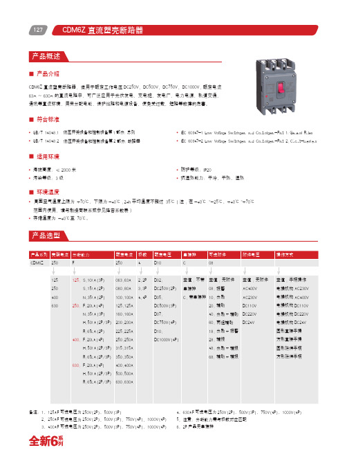
127CDM6Z 直流塑壳断路器,适用于额定工作电压DC250V 、DC500V 、DC750V 、DC1000V,额定电流63A ~630A 的直流电路中,可广泛应用于光伏发电、充电桩、发电厂、电力电源、轨道交通、通讯等直流环境,用来分配电能,保护线路和电源设备,使免受过载、短路等故障的危害。
■ 产品介绍备注:1、125AF 可选电压为250V(2P)、500V(3P)2、250AF 可选电压为250V(2P)、500V(3P)、750V(4P)、1000V(4P)3、400AF 可选电压为250V(2P)、500V(3P)、750V(4P)、1000V(4P)4、630AF 可选电压为250V(2P)、500V(3P)、750V(4P)、1000V(4P)5、注意:分断能力需与极数对应匹配6、2P 产品无串接排海拔高度:≤2000米污染等级:3级■ 适用环境防护等级:IP20抗湿热能力:干冷、干热、湿热■ 符合标准GB/T 14048.1 低压开关设备和控制设备第1部分:总则GB/T 14048.2 低压开关设备和控制设备第2部分:断路器IEC 60947-1 Low Voltage Switchgear and Controlgear-Part 1:General Rules IEC 60947-2 Low Voltage Switchgear and Controlgear-Part 2:Circuit-breakers■ 环境温度周围空气温度上限为 +70℃,下限为-40℃;24h 平均温度不超过 35℃(注:在-40℃ ~-25℃、+40℃~+70℃范围内使用,请与制造商联系或参见降容系数表)存储温度为 -40℃至 70℃。
128■ 单卖附件型号解释备注:1、扩展端子,也叫附件板,或者接线铜排2、AL/MX/OF有分带端子与带引线两种类型3、MX分励电压类型:DC24V、DC110V(定制)、DC220V(定制)、AC230V、AC400V4、只有250壳架有端子罩129CDM6Z直流塑壳断路器技术参数型号CDM6Z-125CDM6Z-250壳架等级125250额定电流In(A)63、80、100、125100、125、160、200、225、250额定绝缘电压Ue(V)10001000额定冲击耐受电压Uimp(kV)88额定电压Ue(V)DC250V DC500V DC250V DC500V DC750V DC1000V 极数(2P/3P/4P)23234分断能力S N S H R N H F额定极限短路分断能力Icu(kA)1535105065355020额定运行短路分断能力Ics(kA)1535105065355020机械寿命有维护2500025000免维护2000020000电气寿命80008000安装方式固定板前●●隔离功能●●选择性类别A A认证CCC、CE CCC、CE飞弧距离(mm)<50<50可选附件分励脱扣器●●辅助触点(1开1闭)●●辅助触点(2开2闭)●●报警触头●●辅助报警触头●●圆形直接手操●●方形直接手操●●圆形延伸手操●●方形延伸手操●●交流电操●●直流电操●●相间隔板●●串接排(3P/4P)●(仅3P)●外形尺寸长 L150165165宽 W92107142高 H93.59494CDM6Z直流塑壳断路器130CDM6Z-400CDM6Z-630CDM6Z-800 400630800 250、315、350、400400、500、630600、700、800 100010001000888 DC250V DC500V DC750V DC1000V DC250V DC500V DC750V DC1000V DC250V 2342342H R H R F H R H R F H R 506550652050655065205065 506550652050655065205065 20000150001000015000100008000800065005000●●●●●●A A BCCC、CE CCC、CE CCC、CE<100<100<100●●●●●●●●●●●●●●●●●●●●●●●●●●●●●●●●●●●●●●●257257257257280150198150198210107.5107.5107.5107.5158131■ 降容表说明周围温度不在+40℃时,需要校验时的额定电流进行温度补偿修正值温度补偿修正系数表海拔降容系数高度在2000米以下不会对断路器性能有影响。
德力西电气 DZ47sY浪涌保护器产品选型手册2022年第2版 产品说明书

CDM3LS 系列剩余电流动作断路器17-26DZ47sY 电涌保护器36-38DZ47sLES 小型漏电保护断路器33-35CDEN1系列照明配电箱45-46CDEN1X 系列光纤箱47-48CDPZ30v 系列照明配电箱42-44C物料描述:CDM3S产品选型CDM3S 系列塑料外壳式断路器电气附件备注:除欠压外电气附件形式为引线0.5m ,可选1m, 1.5m, 2m 欠压默认形式为端子分励电压类型:AC400V , AC230V/DC220V , DC24V , DC110V/AC110V 欠压电压类型:AC400V , AC230V(仅支持左侧安装)操作附件其他附件产品选型CDM3S 系列塑料外壳式断路器技术参数CDM3S系列塑料外壳式断路器技术参数CDM3S系列塑料外壳式断路器CDM3S固定式板后安装开孔尺寸一体式(CDM3S-63~250)分体式(CDM3S-400~800)安装孔尺寸图孔图(mm)CDM产品选型CDM3LS 系列剩余电流动作断路器物料描述:CDM3LS电气附件备注:除欠压外电气附件形式为引线0.5m ,可选1m, 1.5m, 2m 欠压默认形式为端子分励电压类型:AC400V , AC230V/DC220V , DC24V , DC110V/AC110V 欠压电压类型:AC400V , AC230V(仅支持左侧安装)操作附件其他附件产品选型CDM3LS 系列剩余电流动作断路器技术参数CDM3LS系列塑料外壳式断路器技术参数CDM3LS系列塑料外壳式断路器X-X:为基座中心轴,下同Y -Y:为手柄中心轴,下同3极/4极2极单位:mm 露出面盖及拨动手柄露出拨动手柄注:2P 无板后接线CDM3LS 固定式板后安装开孔尺寸一体式(CDM3LS 125~250)分体式(CDM3LS 400~800)安装孔尺寸图孔图(mm)CDM3LS-125~250安装孔尺寸图产品选型DZ47sLES 小型漏电保护断路器1P+N 、2P 3P 、3P+N4P技术参数DZ47sLES 小型漏电保护断路器1P+N/2P 3P/3P+N/4P安装尺寸DZ47sLES 小型漏电保护断路器产品选型DZ47sY 电涌保护器接线图DZ47sY 安装示意图TT 系统安装示意图接线图TN -S 系统安装示意图TT 系统安装示意图TN -S 系统安装示意图TT 系统安装示意图PE L1L2L3N L2L3L1TN -S 系统安装示意图TT 系统安装示意图TN-S 系统安装示意图TN-C 系统安装示意图L N TN -S 系统安装示意图TT 系统安装示意图图TT 系统安装示意图TT 系统安装示意图技术参数DZ47sY电涌保护器接线能力:1.5mm 2(max)Umax :AC125V lmax :1ADZ47sY -II 20/40/65kA DZ47sY -II 80/120kA 外形及安装尺寸(mm )安装尺寸DZ47sY 电涌保护器DZ47sY -IIIDZ47sY -I+II 12.5/15/25kADZ47sY -II 160kA安装尺寸DZ47sY 电涌保护器产品选型DZ47SCB 电涌保护器专用保护装置DZ47SCB-120外形及安装尺寸(mm )技术参数DZ47SCB电涌保护器专用保护装置注:仅适用于电压限制型电涌保护器使用技术参数电气特性产品选型CDPZ30v 系列照明配电箱产品选型单排4CDPZ30VR4J CDPZ30VR4CDPZ30VR412CDPZ30VR4JT CDPZ30VR4T CDPZ30VR412T 6CDPZ30VR6J CDPZ30VR6CDPZ30VR612CDPZ30VR6JT CDPZ30VR6T CDPZ30VR612T 8CDPZ30VR8J CDPZ30VR8CDPZ30VR812CDPZ30VR8JT CDPZ30VR8T CDPZ30VR812T 10CDPZ30VR10J CDPZ30VR10CDPZ30VR1012CDPZ30VR10JT CDPZ30VR10T CDPZ30VR1012T 12CDPZ30VR12J CDPZ30VR12CDPZ30VR1212CDPZ30VR12JT CDPZ30VR12T CDPZ30VR12T12T15CDPZ30VR15J CDPZ30VR15CDPZ30VR1512CDPZ30VR15JT CDPZ30VR15T CDPZ30VR1512T 18CDPZ30VR18J CDPZ30VR18CDPZ30VR1812CDPZ30VR18JT CDPZ30VR18T CDPZ30VR1812T 20CDPZ30VR20DJ CDPZ30VR20D CDPZ30VR20D12CDPZ30VR20DJT CDPZ30VR20DT CDPZ30VR20D12T 24/CDPZ30VR24D CDPZ30VR24D12/CDPZ30VR24DT CDPZ30VR24D12T 双排20/CDPZ30VR20CDPZ30VR2012/CDPZ30VR20T CDPZ30VR2012T 24/CDPZ30VR24CDPZ30VR2412/CDPZ30VR24T CDPZ30VR2412T 30/CDPZ30VR30CDPZ30VR3012/CDPZ30VR30T CDPZ30VR3012T36/CDPZ30VR36CDPZ30VR3612/CDPZ30VR36T CDPZ30VR3612T 40/CDPZ30VR40CDPZ30VR4012/CDPZ30VR40T CDPZ30VR4012T 三排45/CDPZ30VR45CDPZ30VR4512/CDPZ30VR45T CDPZ30VR4512T 54/CDPZ30VR54CDPZ30VR5412/CDPZ30VR54T CDPZ30VR5412T60/CDPZ30VR60CDPZ30VR6012/CDPZ30VR60T CDPZ30VR6012T 四排72/CDPZ30VR72CDPZ30VR7212/CDPZ30VR72T CDPZ30VR7212T 80/CDPZ30VR80CDPZ30VR8012/CDPZ30VR80T CDPZ30VR8012T单排4CDPZ30VM4J CDPZ30VM4CDPZ30VM412CDPZ30VM4JT CDPZ30VM4T CDPZ30VM412T 6CDPZ30VM6J CDPZ30VM6CDPZ30VM612CDPZ30VM6JT CDPZ30VM6T CDPZ30VM612T 8CDPZ30VM8J CDPZ30VM8CDPZ30VM812CDPZ30VM8JT CDPZ30VM8T CDPZ30VM812T 10CDPZ30VM10J CDPZ30VM10CDPZ30VM1012CDPZ30VM10JT CDPZ30VM10T CDPZ30VM1012T 12CDPZ30VM12J CDPZ30VM12CDPZ30VM1212CDPZ30VM12JT CDPZ30VM12T CDPZ30VM12T12T15CDPZ30VM15J CDPZ30VM15CDPZ30VM1512CDPZ30VM15JT CDPZ30VM15T CDPZ30VM1512T 18CDPZ30VM18J CDPZ30VM18CDPZ30VM1812CDPZ30VM18JT CDPZ30VM18T CDPZ30VM1812T 20CDPZ30VM20DJ CDPZ30VM20D CDPZ30VM20D12CDPZ30VM20DJT CDPZ30VM20DT CDPZ30VM20D12T 24/CDPZ30VM24D CDPZ30VM24D12/CDPZ30VM24DT CDPZ30VM24D12T 双排20/CDPZ30VM20CDPZ30VM2012/CDPZ30VM20T CDPZ30VM2012T 24/CDPZ30VM24CDPZ30VM2412/CDPZ30VM24T CDPZ30VM2412T 30/CDPZ30VM30CDPZ30VM3012/CDPZ30VM30T CDPZ30VM3012T36/CDPZ30VM36CDPZ30VM3612/CDPZ30VM36T CDPZ30VM3612T 40/CDPZ30VM40CDPZ30VM4012/CDPZ30VM40T CDPZ30VM4012T 三排45/CDPZ30VM45CDPZ30VM4512/CDPZ30VM45T CDPZ30VM4512T 54/CDPZ30VM54CDPZ30VM5412/CDPZ30VM54T CDPZ30VM5412T60/CDPZ30VM60CDPZ30VM6012/CDPZ30VM60T CDPZ30VM6012T 四排72/CDPZ30VM72CDPZ30VM7212/CDPZ30VM72T CDPZ30VM7212T80/CDPZ30VM80CDPZ30VM8012/CDPZ30VM80T CDPZ30VM8012T技术参数CDPZ30v 系列照明配电箱外形及安装尺寸单排4175155150130///6215210190191(1*φ6+5*φ5)*1(1*φ6+5*φ5)*1一零一地6孔*1根8215245190227102652892402631226532524030015265379240354单位:mm 暗装安装尺寸CDPZ30v 系列照明配电箱产品选型CDEN1系列照明配电箱注:位数是指18mm的倍数,1位宽度是18mm.选型举例:CDEN1AR13,表示CDEN1-13回路标准型暗装乳白活动门厚1.0mm安装尺寸CDEN1系列照明配电箱外形及安装尺寸单位: mm产品概述CDEN1X 系列光纤箱• 设计新颖,安装方便、快捷,经济实用;• 统一管理,采用形象化标识,系统连接状况一目了然;• 支持视频、语音、数据、安防监控信号传输及远程智能控制;• 灵活性、高效性及高可靠性;• 兼容性及开放性,使用接口以模块式安装;• 箱体预埋,简易方便,美观大方;特点安装尺寸CDEN1X 系列光纤箱光纤箱乳白02376323300350120CDEN1G02W 03426323300400120CDEN1G03W 金属01345300250300120CDEN1G0102395350300350120CDEN1G0203445350300400120CDEN1G03CDEN1XG01CDEN1X 光纤箱 小箱 金属面板 厚1.0mm CDEN1XG01J CDEN1X 光纤箱 小箱 金属面板 厚0.8mm CDEN1XG01W CDEN1X 光纤箱 小箱 乳白面板 厚1.0mm CDEN1XG01WJ CDEN1X 光纤箱 小箱 乳白面板 厚0.8mm CDEN1XG02CDEN1X 光纤箱 中箱 金属面板 厚1.0mm CDEN1XG02J CDEN1X 光纤箱 中箱 金属面板 厚0.8mm CDEN1XG02W CDEN1X 光纤箱 中箱 乳白面板 厚1.0mm CDEN1XG02WJ CDEN1X 光纤箱 中箱 乳白面板 厚0.8mm CDEN1XG03CDEN1X 光纤箱 大箱 金属面板 厚1.0mm CDEN1XG03J CDEN1X 光纤箱 大箱 金属面板 厚0.8mm。
德力西 CDM3LS剩余电流动作断路器英文说明书

PEAK SeriesCDM3S/3LSMoulded Case Circuit BreakerUser Manual for ExternalAccessoriesPlease carefully read this manual before the installation andoperation of this product,and keep it properly for future reference.●It is prohibited to operate the switch disconnector with your wet hands;●It is prohibited to touch the conductive part during operation;●Make sure that the product is de-electrified during the maintenance and service;●It is prohibited to use the short circuit method to test the product;Caution:●The installation,maintenance,and service shall be carried out by the qualified professionals;●The characteristics of the product have been set in factory,and the product cannot be installed,disassembledor adjusted without permission during operation;●Please confirm that the rated voltage,rated current,frequency,and characteristics of the product meet theworking requirements before use;●The exposed wire or copper busbar on the terminal block shall be subject to the insulation treatment to thesafety of insulation;●If found damage or abnormal sound when unpacking the product,please stop the operation immediately andcontact the supplier;●To purchase accessories,please select the supporting accessories provided by the company to ensure thequality;●The company will not be responsible for any severe consequences caused by the use of the accessories notprovided by the company;●When scrapping the product,please dispose the product waste properly;thanks for your cooperation.Test:●The accessories have passed the insulation test specified by the standard in the factory,and re-test is notrequired.Please especially follow the information marked withExternal Accessories of CDM3S/3LS1External Protective Accessories of CDM3S/3LS1.1Long Terminal Cover(installed:IP30)●Installation dimensionsProduct model Product modelBreak-off places1.To install manual or motor mechanism,please remove the break-off places.2.X-X means the center axis of the base,and Y-Y means the center axis of the operating handle(the same below) Installation stepsStep1Insert the base plate in the direction shown in figure Step2Connect the wire by client Step3Break the grid inward with aneedle-nose pliers for removal accordingto the operation requirementsSelf-tapscrews ST2Self-tap screws ST1Step4Insert the long terminal cover in the direction shown in figure Step5Lock the terminal cover and themiddle cover with self-tap screws ST1Step6Lock the terminal cover and thebase plate with self-tap screws ST2Caution:For all break-off places on the terminal cover,please break them inwards the terminal cover.1.2Short Terminal Cover●Installation dimensionsProduct model Product modelBreak-offplacesCaution:To install manual or motor mechanism,please remove the break-off places.●Installation stepsRefer to the Steps2~5Installation steps of long terminal1.3Zero Flashover Hood(combination of short terminal cover and arc suppression components)●Installation steps1)Split type:Suitable for the following models:CDM3S-160F/250F/400F/630F/630bF/800F, CDM3LS-160F/250F/400F/630F/800F products.White paperboard fold lineShort terminal coverStep1:Connect the wire by user Step2:Bend the white paperboard90°along with the fold line with aslotted screwdriver Step3:Push the arc suppressionhood to the direction shown in figureto block the middle coverStep4:Insert the short terminalcover,and lock the screw ST12)Integrated type:Suitable for the following models:CDM3S-125bF and CDM3LS-125F products.Zero flashover hood at the inlet terminalTerminal cover at the outlet terminalStep3:Insert the zero flashover assembly,and lock the screwST1Caution:1.The installation steps1~2of the integrated type zero flashover assembly refer to the installation steps1-2ofthe split type installation;2.Please conduct the Step2Fold the white paperboard,and continue to the sequent operations;3.After installation is complete,please install the phase partition before operation.1.4Handle Position Lock●Handle position lock dimensionsProduct modelProduct modelDiameter of matched padlock of A holeDiameter of matched padlock of B holeSeal diameter of C holeCircuit breaker handle locking positionOFF position (Re-trip)ON positionOFF position (Re-trip)●Handle position lock installationmethodStep 1:Stagger the handle position locks Step 2:Insert the handle position lock intothe slot on the handleStep 3:Hang the padlock with arecommended diameterCaution:1.The padlock shall be provided by the user2.Before installation,turn the handle to an appropriate position before installation.External Operating Accessoriesof CDM3S/3LS2.1Manual Operating Mechanism (Direct,Extended)●Optional handle type and dimensionsRound type:suitable for CDM3S-63~800CDM3LS-125~800Square type:suitable for CDM3S-63~250CDM3LS-125~250Square type:suitable for CDM3S-400~800CDM3LS-400~800Square type:suitable for CDM3S-1600●Size of mounting hole on handle cabinet doorHinge Hinge Hole on round handle cabinet door Hole on square handle cabinet door Round Square●Operating handle features:1.When the circuit breaker is in the ON state,do not open the cabinet door;2.If there is a fault when the operating handle or mechanism is in the ON state,press the emergency unlock button on the operating handle to open the cabinet door (only the round handle has this feature):3.In the OFF or ON state,press the white mark on the round operating handle to pop up the padlock plate,and then hang the padlock on the lock plate (the lock with a diameter 5~8mm shall be provided by the user).●Outline dimensions of manual operating mechanismDepth of square holeMounting plateDistance from square shaft head to mounting plateProduct model Product modelG*direct manual operating mechanismG*extended manual operating mechanism (bydefault)Height of round handleH1Height of square handleH1Offset between the center of base and the center of handle,KCaution:1.95mm is optional for A*63-250,and 125mm is optional for 400-800;2.G*if other length size is required,please contact the manufacturer for customization;3.The operation of the CDM3S-400/630/630b,and CDM3LS-400manual mechanism is conducted not at the center,and the K value must be considered when drilling the hole;Cabinet door panel Emergency unlockLock plate PadlockLock plate PadlockCabient door panel●Manual operating mechanism installation method1)Suitable for CDM3S-63/100/125b/400/630,and CDM3LS-125/400Step1Insert the circuit breaker handle into the manual operating mechanism,and lock the screws Inspection stepInsert the square shaft and lock the screw with a screwdriver, assemble the handle,and check the product for power-on, power-off and re-tripoperation2)Suitable for CDM3S-160/250/1600,CDM3LS-160/250Step1Remove four screws of middle cover of circuitbreaker Step2Insert the circuit breaker handle into the manual operating mechanism,and lock screws;the inspection steps are same as above3)Suitable for CDM3S-630b/800and CDM3LS-630/800Step1Install the manual mechanismscrew Step2Insert the circuit breaker handle into the manual operating mechanism,and lock screws;the inspection steps are same as above2.2Special Handle for Machine Tools(suitable for CDM3S-63/100)●Outline dimensions of handle of machine toolsThread sideInstallation dimensions not including dust cover Installation dimensions including dust cover(cabinet body:IP40after installed)To open the cabinet door inthe event of an emergencywithout power outage,please Cabinet doorturn this screw slightly counterclockwise to open the cabinet doorInstallation dimensions including door curtain lock●Install special handle of machine toolLock plateCabient doorHousingMounting screwInsert the handle of machine tools into the manual operating mechanism,and then lock the screws Dust cover assembly:Lock the lock plate,cabinet door,andhousing from inward from outward withscrewsSize of hole on cabinet doorIf no dust cover is installed,four holes arenot drilled2.3Motor mechanism●Installation dimensions of motor mechanismMotor mechanism Cabinet doorProduct model Product modelInstallation method1)Suitable for CDM3S-63~100/1600Step1Step2Turn the handle to the OFF position Install the motor mechanism and tighten the screws and nuts 2)Suitable for CDM3S-125b~800and CDM3LS-125~800Thread sideStep1Install the motor mechanism mounting rod Step2Turn the handle to the OFF positionStep3Install the motor mechanism and lock thescrewsCaution:1.Check whether the handle is inserted into the motor mechanism before operation;2.The CDM3S-1600adopt the insert nuts provided with the base.Motor mechanism wiring diagramPower supplyFigure:1.P1and P2are connected to the power cord;when the wire is DC wire,P1is connected to“+”and P2is connected to“-”;2.S1is common terminal;the S1and S2are connected for power-on,and the S1and S4are connected for power-off.Caution:1.When the circuit breaker with a motor mechanism trips,the motor mechanism must be first powered offbefore power-on;2.For manual operation,operate the product180°clockwise;operation in the counter clockwise is forbidden;3.Voltage withstand test:the50HZ,1890V power frequency withstand voltage can be applied between theinlet terminals P1and P2(not including S1,S2,S4)of the power supply and the mounting screw of the motor mechanism when test(the withstand voltage test is prohibited at the rated voltage DC24V)4.When wiring motor mechanism,it is prohibited to connect P1,P2with S1,S2,and S4.Technical parameters of motor mechanismMotor mechanismmodel Operating current(A)Motor powerconsumption(W)Operating current(A)Motor powerconsumption(W)Operating current(A)Motor powerconsumption(W)*The operation frequency of63~250motor mechanism is not greater than120times per hour,and the operation time is≤1s.*The operation frequency of400~800motor mechanism is not greater than120times per hour,and the operation time is≤1.5s.*Rated control power voltage:At AC230V/DC220V,the allowable voltage tolerance range AC is 195.5~253V/DC187~242V.*Rated control power voltage:At AC/DC110V,the allowable voltage tolerance range AC is93.5~121V/DC 93.5~121V.*Rated control power voltage:At AC400V,the allowable voltage tolerance range is340~440V.*Rated control power voltage:At DC24V,the allowable voltage tolerance range is21.6~26.2V.External installation accessories of CDM3S/3LS3.1Install TH35-7.5Type Steel Mounting Rail(suitable for CDM3S-63~100)●Installation dimensions of railPull the limit stop down to remove the product Pull the limit stop down to remove the product Installation dimensions of35mm single rail Installation dimensions of35mm dual rail●Rail installation methodLock the circuit breaker and bracket with screws3.2Fixed type back-panel●Fixed type back-panel dimensionsMountingplate MountingplateMountingplateFixed type back-panel(screw) CDM3S-63~250CDM3LS-125~250Fixed type back-panel(horizontal)CDM3S-400~630CDM3LS-400Fixed type back-panel(horizontal)CDM3S-800CDM3LS-630~800Product model Product model DimensionlocationFixed type back-panel dimension tableInlet terminalOutlet terminalInlet terminalOutlet terminalInlet terminalOutlet terminalInlet terminalOutlet terminalInlet terminalOutlet terminalInlet terminalOutlet terminalInlet terminalOutlet terminalInlet terminalOutlet terminalProduct model Product model Numberof polesFixed type back-panel horizontal hole dimension tableFixed type back-panel installation dimensions3.3Plug-in back-panel(horizontal)Plug-in type phase partitionMounting plate Mounting plateIntegrated type CDM3S-63~250Split type CDM3S-400~800Mounting hole CDM3LS-125~250Product Product Numbermodel model of poles Mounting hole dimensions3.4Plug-in type front-panelPlug-in type phase partitionInsulating base plateMounting plateProduct model Product model Number Plug-in type front-panel outline dimensions,mm Mounting hole dimensions,mm of poles3.5Pull-out type back-panel horizontal●Pull-out type back-panel horizontal dimensionsMounting plateProduct model Number of Pull-out type back-panel outline dimension drawingpoles●Pull-out type back-panel horizontal installation dimensionsProduct model Number of poles Pull-oiut type back-panel horizontal mounting hole drawingExpansion terminal● 4.1Straight busbarSuitable for CDM3S-63~800Suitable for CDM3S-1600CDM3LS-125~800Product model Product model Number of poles Corresponding dimensions of expansion busbar4.2Left and right expansion busbar(suitable for CDM3S-63~630and CDM3LS-125~400)Left and right expansion busbar installation dimensions Left and right expansion busbar dimensionsProduct model Product model Corresponding dimensions of pole number interphase expansion busbar Junction poleExternal type Buit-in typeProduct model Product model Number Installation dimensionsof polesCDM3S thermomagnetic type communication moduleInstallation dimensions of communication moduleProduct model Product model Number Installation dimensionsof poles Communication module functionPower indicator Code switch high addressControl indicator Code switch low address Reset buttonCabinet door display functionMotor mechanism control function areaGrounding protection areaPower supply area Auxiliary output without power function area Alarm output without power function area Auxiliary input without power function area Alarm input without power function area 485communicaiton funciton area●Cabinet door display function The cabinet door display adopts fixed addressing mode to connect the cabinet door display screen with the communication module through the communication interface T,thereby realizing the information interaction between the communication module and the cabinet door erscan select the company's special communication module and can develop their own display screen (for development protocol,please contact the manufacturer),and follow the RJ45wiring method.The effective interface of this communication module is shown in figure:the interface 1/2/3corresponds to interface A,the interface 6/7/8corresponds to interface B,and the interface 4/5is empty.●Motor mechanism control function area Contacts 1(S1),2(S2)and 3(S4)are the connection contacts of the motor mechanism control area to connect each interface at the communication module motor mechanism control function area to the corresponding motor mechanism interface to realize the power-off and power-on operation of the motor mechanism through the communication module.The communication module and motor mechanism assembly effects are shown in the figure.Motor mechanism Motor mechanismMotor mechanism,communication module and product assembly effect diagram Motor mechanism and communication module wiring diagram●Auxiliary input without power function areaThe auxiliary input without power function area receives the signal from the auxiliary accessory;the contact18 (F12)is a normally open contact,the contact19(F14)is a normally closed contact,and the contact20(F11)is a common contact used to connect the contacts18,19and20of the communication module with the F12,F14,and F11of the auxiliary,respectively;that is,the communication module is used to realize the product ON/OFF signal reading function,and to transfer the signal to the auxiliary input without power function area.The wiring method sees the communication module function wiring diagram.●Alarm input without power function areaThe alarm input without power function area receives the signal from the alarm accessory.The contacts21(B14) and22(B11)are connected to the alarm contacts B14and B11,respectively.This function area can transfer the alarm signal to the alarm output without power function area,and the wiring method is shown in the communication module function wiring diagram.●Auxiliary output without power function areaThe auxiliary output without power function area receives the signal from the alarm input without power function area to indicate the ON/OFF state of circuit breaker.The contact11means normally open contact,the contact12 means normally closed contact,and the contact13means the common end.The wiring method of the external accessories of the customer is shown in the communication module function wiring diagram.The indicator L1is lit and the indicator L2is off when the circuit breaker works normally;when the circuit breaker is powered off, the indicator L1is off,and the indicator L2is lit.●Alarm output without power function areaThe alarm output without power function area receives the signal from the alarm input without power function area to indicator the trip state of circuit breaker.For example,the communication module function wiring diagram is shown in figure;when the contacts14and15are connected,the indicator L3is off if the circuit breaker can work normally,and the indicator L3is lit if the circuit breaker trips.Communication module function wiring diagram●Code switch function areaThe code switch is composed of high address and low-bit addressing.When the485communication interface is used for networking,a total of99groups of addressing addresses from01to99is provided.Baud rate:9600,data bits:8,stop bits:1,check digit:no.●485communication function areaThe485communication function area provides a communication interface for the intelligent interaction of circuit breaker,and the user can realize the remote control and remote communication of the product through the accessories of the host computer software matching with the motor mechanism and auxiliary alarm;the user can also communicate multiple circuit breaker information through networking;to realize this function,the communication module protocol and the addressing method adopted shall be followed.The communication module can easily access the ON/OFF state through the485communication interface,and realize the remote control of the circuit breaker.The ON/OFF addressing mode of the circuit breaker is shown in the table.Address:Delixi High-Tech Industrial Park,Liushi Town,Yueqing City,Zhejiang P.C:325604 Tel:(86-577)61778888Fax:(86-577)61778000Service hotline:400-826-8008The first edition of this user manual was issued in Oct.2021。
