涂层冲击试验标准
油漆耐冲击强度标准

油漆耐冲击强度标准一、油漆耐冲击标准及测试方法介绍油漆是广泛应用于建筑、汽车、工业设备等领域的一种涂层材料。
在实际使用过程中,油漆往往会受到来自外界的机械冲击,因此耐冲击性能成为了衡量油漆质量的一个重要指标。
测试油漆的耐冲击性能,需要借助专门的测试设备,并根据一定的标准进行测试评价。
二、常见的油漆耐冲击标准1. ISO 6272:这是一种国际标准,适用于测定涂层材料的耐冲击性能。
该标准要求用大钳头进行冲击,以确定涂层的最小厚度和韧性。
2. ASTM D2794:这是美国材料和试验协会制定的标准,适用于测定涂层材料的耐冲击性能。
该标准要求用冲击器在材料上均匀施加冲击,从而测定涂层的冲击强度。
除此之外,还有一些国内外的标准,如国家标准GB/T 1732-2010和日本标准JIS K 5600-5-10等。
三、油漆耐冲击测试方法进行油漆耐冲击实验时,需要使用专用的测试设备,如冲击实验机或者恒定重量冲击器。
以ASTM D2794标准为例,具体测试方法如下:1. 将试验板固定在平坦的支撑板上,以确保涂层不会移动或变形。
2. 将恒定重量的冲击器置于一定高度,然后释放冲击器使其与试验板表面水平碰撞。
3. 重复进行冲击测试,每次冲击后都必须进行检查和记录,以确定涂层是否受到损坏。
4. 根据每组测试结果计算出涂层的冲击强度,并根据标准进行评价。
实验的结论应当包括涂层是否受到损坏,涂层的冲击强度等信息,以帮助评价涂层的耐冲击性能。
四、油漆耐冲击性能的评价标准在进行油漆耐冲击性能测试时,要根据标准确定评价标准。
以ISO 6272为例,该标准根据涂层材料与底材的粘结强度、涂层韧性和涂层厚度等因素,将涂层的耐冲击性能分为三个等级:G0、G1和G2。
其中,G0表示无法承受冲击,G1表示合格但耐冲击性能较低,G2表示优良的耐冲击性能。
五、总结本文从油漆耐冲击的定义、测试方法、耐冲击标准和评价标准等方面进行了介绍,帮助读者更加了解油漆的耐冲击性能,选择更适合的油漆材料应用于实际工程中。
漆膜耐冲击性测定
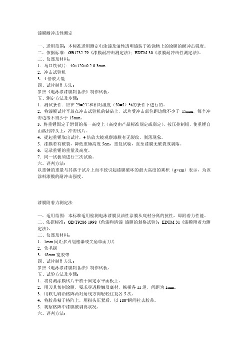
漆膜耐冲击性测定一、适用范围:本标准适用测定电泳漆及油性透明漆装于被涂物上的涂膜的耐冲击强度。
二、依据标准:GB1732-79《漆膜耐冲击测定法》;EDTM-30《漆膜耐冲击性测定法》。
三、仪器及材料:1.马口铁试片:40×120×0.2-0.3mm2.冲击试验机3.4倍放大镜四、试片制作方法:参照《电泳漆漆膜制备法》制作试板。
五、测定方法及步骤:1.测试条件:应在23±2℃和相对湿度(50±5)%的条件下进行的。
2.将漆膜试片平放在冲击试验机的钻砧上,试片受冲击部位距边缘不少于15mm,每个冲击边缘不得少于15mm。
3.将重锤固定于滑筒的某一高度上(高度由产品标准规定或商定),按压控制钮,使重锤自由落到冲头上,冲击试片。
4.提起重锤取出试片,4倍放大镜观察漆膜有无裂纹,剥落现象。
5.漆膜若有破裂,降低重锤高度5cm,重复试验,直至漆膜无破裂或剥落。
6.记录重锤的重量及高度。
7.同一试板须进行三次试验。
六、评判方法:以重锤的重量与其落于试片上而不致引起漆膜破坏的最大高度的乘积(g×cm)表示,为该涂料漆膜的耐冲击强度。
漆膜附着力测定法一、适用范围:本标准适用检测电泳漆膜及油性涂膜从底材分离的抗性,即附着力性能。
二、依据标准:GB/T9286-1998《色漆和清漆漆膜的划格试验》:EDTM-31《漆膜附着力测定法》。
三、仪器及材料:1.1mm间距多刃划格器或尖角单面刀片2.软毛刷3.48mm宽胶带四、试片制作方法:参照《电泳漆漆膜制备法》制作试板。
五、试验方法及步骤:1.将待测涂膜试片平放于固定水平面板上。
2.用刀具切割涂膜,要求穿透膜触及底材,纵横各11道,间距为1mm。
3.用软毛刷沿格阵两对角线方向轻轻往复各5次。
4.将胶带粘于格阵上,用指头压紧后,以180°瞬间拉去胶带。
5.观察格阵中漆膜被剥离状况。
六、评判方法:分级说明0 切割边缘完全平滑,无一格脱落1 在切口交叉处有少许涂层脱落,但交叉切割面积受影响不能明显大于5%2 在切口交叉处和/或沿切口边缘有涂层脱落,受影响的交叉切割面积明显大于5%,但不能明显大于15%3 涂层沿切割边缘部分或全部以大碎片脱落,和/或在格子不同部位上部分或全部剥落,受影响的交叉切割面积明显大于15%,但不能明显大于35%,但不能明显大于35%4 涂层沿切割边缘大碎片剥落,和/或一些方格部分或全部出现脱落受影响的交叉切割面积明显大于35%,但不明显大于65%5 剥落的程度超过4级。
漆膜耐冲击测定法

漆膜耐冲击测定法漆膜耐冲击测定法用于评估涂层表面对冲击负荷的抵抗能力。
该方法根据国际标准规范,通过模拟实际使用条件下的冲击力,评估涂层的抗冲击性能,可用于涂层的质量控制和改良。
在本文中,我将详细介绍漆膜耐冲击测定法的原理、步骤及其在实际应用中的重要性。
首先,让我们了解漆膜耐冲击测定法的原理。
该方法利用冲击试验仪进行实验,冲击试验仪通常由一个撞击头、撞击杆和撞击座组成。
撞击头上有一个固定垂直释放的撞击针,将在一定高度上释放,撞击杆受到冲击后将穿过涂层,通过检测撞击杆上的变形来评估涂层的耐冲击性能。
接下来,让我们看看漆膜耐冲击测定法的步骤。
首先,准备好要测试的涂层样品。
样品通常是矩形板材,尺寸要根据标准规定进行选择。
然后,将样品放置在冲击试验仪上的撞击座上,并根据标准规定调整撞击头的高度。
接下来,释放撞击针撞击涂层,并记录撞击杆所穿过的涂层深度。
可以重复进行多次测试来获取平均结果。
漆膜耐冲击测定法在实际应用中具有重要意义。
首先,它可以用于评估涂层的质量。
高质量的涂层应具有较高的耐冲击性能,能够在受到外力冲击时维持较好的完整性。
通过进行耐冲击测试,可以筛选出低质量的涂层,并及时进行改良,提高涂层的耐用性。
此外,漆膜耐冲击测定法也可用于产品开发和研究。
当涂层用于特殊应用时,如汽车涂装、建筑外墙等,其抗冲击性能需求要求较高。
通过进行耐冲击测试,可以评估不同配方、处理工艺的涂层的性能差异,优化涂层配方和工艺参数,以满足产品的特殊要求。
另外,漆膜耐冲击测定法还可用于研究涂层材料的耐候性能。
在户外环境中,涂层会遭受到风雨、紫外线和温度变化的影响。
这些外界因素会导致涂层表面的龟裂、剥落等问题。
耐冲击测试可以模拟部分这些外界因素的影响,评估涂层的耐候性能,为涂层材料的研发提供参考。
综上所述,漆膜耐冲击测定法是评估涂层耐冲击性能的有效方法。
通过具体的实验步骤和原理,我们可以了解到漆膜耐冲击测定法在涂层质量控制和改良、产品开发和研究以及涂层材料耐候性能评估方面的重要性。
涂层硬度测试 国际标准

涂层硬度测试国际标准一、测试方法涂层硬度测试国际标准采用肖氏硬度计法进行测试。
肖氏硬度计法是一种静态测量方法,通过测量涂层表面在冲击力下的形变量来评估涂层的硬度。
二、设备要求1.肖氏硬度计:应选用符合国际标准的肖氏硬度计,其精度应符合相关规定。
2.试验环境:试验应在恒温、恒湿的环境中进行,以避免环境因素对试验结果产生影响。
3.试样形状:试样应为平整的矩形片状,尺寸应符合标准规定。
4.冲击力装置:应选用符合标准的冲击力装置,以确保试验结果的准确性。
三、试样准备1.清洁试样:在试验前,应使用清洁剂和干燥的棉布清洁试样表面,以避免污染物对试验结果产生影响。
2.涂层厚度测量:在试样表面选定若干个测量点,使用测厚仪测量涂层的厚度,以了解涂层的厚度分布情况。
3.划痕测试:在试样表面选定若干个划痕测试点,使用划痕仪测量涂层的划痕抗力,以了解涂层的耐磨性能。
四、试验步骤1.将试样固定在试验台上,确保试样表面与冲击力装置的冲击面平行。
2.将肖氏硬度计安装到冲击力装置上,调整冲击力大小,使其符合标准规定。
3.对每个测量点进行冲击,记录涂层的形变量和冲击力数值。
4.分析试验数据,计算涂层的平均硬度和标准偏差。
五、结果分析1.涂层硬度值应在规定的测量范围内,且应具有一致性。
2.涂层硬度值应与基体材料、涂层成分、涂层厚度等因素有关。
3.分析涂层硬度的均匀性,以及不同工艺参数对涂层硬度的影响。
4.根据试验数据,对涂层的性能进行评价,并提出改进意见。
六、涂层硬度的应用涂层硬度是评估涂层性能的重要指标之一,它可以反映涂层的硬度和耐磨性能。
在机械、汽车、航空航天等领域中,涂层硬度的应用非常广泛。
例如,在汽车发动机零件上涂覆硬质涂层可以提高零件的耐磨性和耐腐蚀性,延长使用寿命;在机械零件上涂覆硬质涂层可以增强零件的抗冲击能力和耐磨性,提高工作效率。
因此,涂层硬度的测试对于产品的质量和使用寿命具有重要意义。
七、安全要求在进行涂层硬度测试时,应注意安全操作规程,确保试验人员的人身安全和设备安全。
漆膜冲击试验机使用说明 冲击试验机技术指标
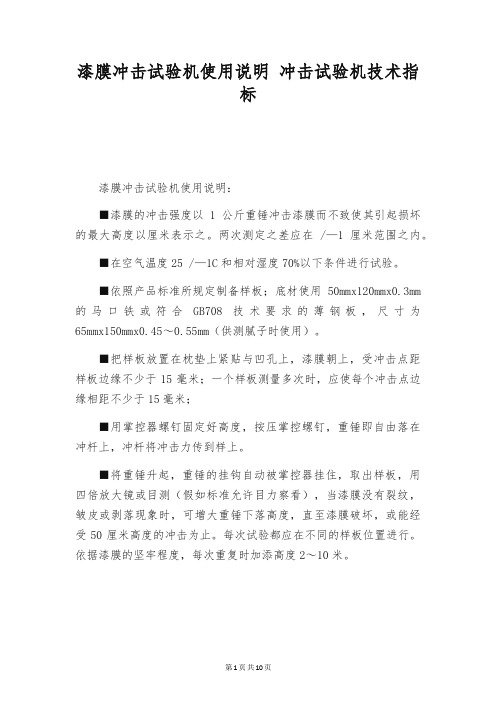
漆膜冲击试验机使用说明冲击试验机技术指标漆膜冲击试验机使用说明:■漆膜的冲击强度以1公斤重锤冲击漆膜而不致使其引起损坏的最大高度以厘米表示之。
两次测定之差应在 /—1厘米范围之内。
■在空气温度25 /—1C和相对湿度70%以下条件进行试验。
■依照产品标准所规定制备样板;底材使用50mmx120mmx0.3mm 的马口铁或符合GB708技术要求的薄钢板,尺寸为65mmx150mmx0.45~0.55mm(供测腻子时使用)。
■把样板放置在枕垫上紧贴与凹孔上,漆膜朝上,受冲击点距样板边缘不少于15毫米;一个样板测量多次时,应使每个冲击点边缘相距不少于15毫米;■用掌控器螺钉固定好高度,按压掌控螺钉,重锤即自由落在冲杆上,冲杆将冲击力传到样上。
■将重锤升起,重锤的挂钩自动被掌控器挂住,取出样板,用四倍放大镜或目测(假如标准允许目力察看),当漆膜没有裂纹,皱皮或剥落现象时,可增大重锤下落高度,直至漆膜破坏,或能经受50厘米高度的冲击为止。
每次试验都应在不同的样板位置进行。
依据漆膜的坚牢程度,每次重复时加添高度2~10米。
相关设备低温试验箱漆膜冲击试验机用途:该产品测定漆膜在不同冲击力作用下不被破坏的耐冲击强度。
漆膜冲击试验机使用前的检查与调整:■检查冲杆中心是否与枕垫块凹孔中心一致,若有偏差时,可调整冲击块紧母上的内六方镙钉。
■检查定位标是否对零线:将重锤放下察看定位标上刻线是否与零线重合,有偏差时可调整定位标两侧的螺钉。
漆膜冲击试验机参数:■导管刻度:120 /—0.5cm。
■冲锤质量:1.0, 1.36, 2.0kg。
■冲头直径:8, 15.87, 20 毫米。
■高度范围:冲锤下落高度0-120、■冲击高度: O~50cm。
■重锤重量: 10001g。
■冲头钢球直径:ф8毫米。
■执行指标:GB/T1723—93 ASTMD2794 ASTMG14 IBCI5C139、弹性冲击试验器标准与用途:该仪器是依据ASTMD2794、ISO6272标准要求设计制造的。
漆膜耐冲击测定法
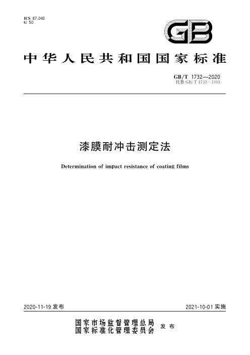
I C S87.040G50中华人民共和国国家标准G B/T1732 2020代替G B/T1732 1993漆膜耐冲击测定法D e t e r m i n a t i o no f i m p a c t r e s i s t a n c e o f c o a t i n g f i l m s2020-11-19发布2021-10-01实施国家市场监督管理总局前言本标准按照G B/T1.1 2009给出的规则起草㊂本标准代替G B/T1732 1993‘漆膜耐冲击测定法“㊂与G B/T1732 1993相比,除编辑性修改外主要技术变化如下:删除了规范性引用文件 G B308 G B708 G B1727 G B1764 ;增加了规范性引用文件G B/T308.1 2013 G B/T9278 G B/T13452.2 G B/T20777 G B/T37356 (见第2章,1993年版的第2章);增加了原理㊁结果的表示(见第3章和第8章);修改了对冲击试验器的冲头及钢球的规定(见4.1,1993年版的3.2.2);删除了冲击试验器的校正方法(见1993年版的3.4);修改了底材的尺寸(见6.1,1993年版的5.1);修改了试板受冲击点边缘与试板边缘的距离和相邻冲击点的边缘的距离(见7.3,1993年版的6.2);增加了重锤高度间隔调整要求和结果观察的光照条件(见7.3);修改了试验报告(见第9章,1993年版的第7章)㊂本标准由中国石油和化学工业联合会提出㊂本标准由全国涂料和颜料标准化技术委员会(S A C/T C5)归口㊂本标准起草单位:中海油常州涂料化工研究院有限公司㊁上海市涂料研究所有限公司㊁标格达精密仪器(广州)有限公司㊁浙江明泉工业涂装有限公司㊁浙江鱼童新材料股份有限公司㊁青岛爱尔家佳新材料股份有限公司㊁深圳广田高科新材料有限公司㊁中航百慕新材料技术工程股份有限公司㊁宣城亚邦化工有限公司㊁宁波新安涂料有限公司㊁河北金达涂料有限公司㊁青岛兴国涂料有限公司㊁江南大学㊁江苏宏泰高分子材料有限公司㊁东莞大宝化工制品有限公司㊁中车长春轨道客车股份有限公司㊁广州市盛华实业有限公司㊁福建万安实业集团有限公司㊁浙江赛飞电器股份有限公司㊁韶关市合众化工有限公司㊁中国建筑科学研究院有限公司㊁河北晨阳工贸集团有限公司㊁普申检测仪器(上海)有限公司㊁浙江飞鲸新材料科技股份有限公司㊂本标准主要起草人:陈刚㊁王玫玫㊁解正坤㊁俞高波㊁茅立安㊁杨亚良㊁王宝柱㊁胡基如㊁张健㊁刘春华㊁胡锦平㊁张然㊁刘彩霞㊁刘仁㊁吴刚强㊁张芳㊁郝博㊁曾玉灵㊁黄文㊁康伦国㊁王连盛㊁楚会来㊁孙德旺㊁颜朝明㊂本标准所代替标准的历次版本发布情况为:G B1732 1979㊁G B/T1732 1993㊂漆膜耐冲击测定法1范围本标准规定了用固定质量的重锤落于冲头上,以冲头撞击试板不引起漆膜破损的重锤降落最大高度(c m)表示的漆膜耐冲击性试验方法㊂本标准适用于漆膜耐冲击性能的测定㊂2规范性引用文件下列文件对于本文件的应用是必不可少的㊂凡是注日期的引用文件,仅注日期的版本适用于本文件㊂凡是不注日期的引用文件,其最新版本(包括所有的修改单)适用于本文件㊂G B/T308.1 2013滚动轴承球第1部分:钢球G B/T3186色漆㊁清漆和色漆与清漆用原材料取样G B/T9271色漆和清漆标准试板G B/T9278涂料试样状态调节和试验的温湿度G B/T13452.2色漆和清漆漆膜厚度的测定G B/T20777色漆和清漆试样的检查和制备G B/T37356色漆和清漆涂层目视评定的光照条件和方法3原理将受试样品施涂于适合的金属底材上,待固化后,将固定质量的重锤从一定高度降落,冲击冲头,使漆膜和底材产生变形㊂可以是正冲(漆膜朝上),也可以是反冲(漆膜朝下)㊂通过逐渐增加重锤降落的高度,测出漆膜经常出现破损的数值点㊂4仪器设备4.1冲击试验器导管最大刻度为(50.0ʃ0.1)c m,分度为1c m,重锤质量为(1000ʃ1)g,能在导管中自由移动㊂冲头上的钢球,直径(8.000ʃ0.015)mm,硬度(H R C)为61~66,应符合G B/T308.1 2013的要求㊂冲击中心与冲模凹槽中心对准,冲头进入凹槽的深度为(2.0ʃ0.1)mm,冲模凹槽应光滑,其直径为(15.0ʃ0.3)mm,凹槽边缘曲率半径为2.5mm~3.0mm㊂冲击试验器示意图见图1㊂说明:1 导管盖;2 重锤控制器;3 刻度;4 冲头导槽;5 冲模;6 底座;7 支架;8 冲头;9 导管;10重锤㊂图1 冲击试验器示意图4.2 放大镜4倍放大镜㊂G B /T 1732 20205 样品按G B /T3186的规定取受试产品的代表性样品(或多涂层体系中的每个产品)㊂按G B /T20777的规定,检查和制备试验样品㊂6 试板6.1 底材除另有规定外,底材为马口铁板或钢板㊂马口铁板或钢板应符合G B /T9271的技术要求,马口铁板尺寸为120mmˑ50mmˑ(0.20mm~0.30mm ),钢板尺寸为150mmˑ70mmˑ(0.45mm~0.55mm )㊂6.2 底材的处理和试板的涂装除另有规定外,按G B /T9271的规定处理每一块底材,然后按规定方法施涂受试产品或体系㊂6.3 干燥和状态调节每一块已涂装的试板应在规定的条件下干燥(或烘烤)以及养护规定的时间㊂烘干等不在G B /T9278规定的条件下养护的试板,试验前应在G B /T9278规定的条件下至少调节16h ㊂6.4 漆膜厚度应规定或商定漆膜厚度㊂漆膜厚度的测定按G B /T13452.2中规定的干膜厚度的测定方法之一进行,以微米(μm )计㊂7 试验步骤7.1 试验次数同一高度位置进行三次试验㊂7.2 试验环境除另有商定外,应在G B /T9278规定的环境条件下进行试验㊂7.3 测试将冲击试验器(4.1)放在稳固的平台上,导管应垂直于水平面㊂通过重锤控制器调节冲击试验器的重锤到某一高度,将试板漆膜朝上(正冲)或漆膜朝下(反冲)平放在底座上,试板受冲击点边缘与试板边缘的距离不得少于10mm ,相邻冲击点边缘的距离不得少于10mm ㊂按压重锤控制器控制钮,重锤自由地降落于冲头上㊂取出试板,在G B /T37356中规定的自然日光或人造日光下,观察试板上漆膜有无裂纹㊁皱纹及剥落现象,如有需要可采用4倍放大镜(4.2)进行观察㊂如果未观察到裂纹㊁皱纹及剥落现象,依次在更高的位置上重复试验直到观察到裂纹㊁皱纹及剥落现象,每次增加的高度是5c m 或5c m 的倍数㊂如果观察到裂纹㊁皱纹及剥落现象,依次在更低的位置上重复试验直到没有观察到裂纹㊁皱纹及剥落现象,每次下降的高度是5c m 或5c m 的倍数㊂注:冲头进入冲模凹槽的深度可能发生变化,可按仪器说明书进行调整㊂G B /T 1732 2020。
ASTMG14-04钢制管道涂层抗冲击性的试验方法(落锤试验)(精)

Designation:G 14–04Standard Test Method forImpact Resistance of Pipeline Coatings (FallingWeight Test 1This standard is issued under the fixeddesignation G 14; the number immediately following the designation indicates the year of original adoption or, in the case of revision, the year of last revision. A number in parentheses indicates the year of last reapproval. A superscript epsilon (e indicates an editorial change since the last revision or reapproval.1. Scope1.1This test method covers the determination of the energy required to rupture coatings applied to pipe under specifiedconditions of impact from a falling weight.1.2The values stated in SI units to three significantdeci-mals are to be regarded as the standard. The values given in parentheses are for information only.1.3This standard does not purport to address all of the safety concerns, if any, associated with its use. It is the responsibility of the user of this standard to establish appro-priate safety and health practices and determine the applica-bility of regulatory limitations prior to use.2. Referenced Documents 2.1ASTM Standards:2G 12Test Method for Nondestructive Measurement of Film Thickness of Pipeline Coatings on SteelG 62Test Methods for Holiday Detection in Pipeline Coat-ings2.2SAE Standard:Grade 52100Steel 33. Summary of Test Method3.1This test method uses a falling fixedweight having a specifieddiameter impact surface, tup , which is restrained vertically and dropped from varying heights to produce impact energies over the required range. Electrical inspection is used to detect resultant breaks in the coating. Impact resistance is determined as the amount of energy required to cause penetra-tion of the coating film.4. Significanceand Use4.1The ability of a pipe coating to resist mechanical damage during shipping, handling, and installation will depend upon its impact resistance. This test method provides a systematic means for screening coating materials with regard to this property.5. Apparatus5.1This test method can be successfully used with impact apparatus conforming to the following specifications:5.1.1Tup —Thetup shall be made up from a tup body and a tup nose having a combined, fixedweight of 1.361kg (3.00lb and shall be used over a drop range of 0.61to 1.22m (2to 4ft. With most coatings, a 1.361-kg (3.00-lbtup dropped through a distance of 914mm (3ft yields suitable results. The tup nose shall have a 15.875-mm (5⁄8-in. hemispherical head.N OTE 1—Frequentreplacement of the tup nose can be avoided if it is cut from steel capable of being hardened to a hardness of Rockwell C/45while retaining an impact toughness of at least 15ft·lb(20.34J. Ball bearings conforming to SAE Grade 52100have also been found suitable for this purpose.5.1.2Drop Tube —Atube 1.52m (5ft long shall be used to contain the tup and guide it during free fall. The drop tube shall be constructed of steel, aluminum, or any other suitably rigid material and internally sized to provide a minimum of friction to the falling tup. A scale shall be attached for measuring the height of drop to the nearest 2.54mm (0.10in..5.1.3Specimen Holder —Thebase plate of the apparatus shall include a device for positioning and holding the pipe specimen on line with the axis of the vertical drop tube.N OTE 2—Anarrangement using a V-notch vise made of metal with spring clamp is recommended for this purpose. Glancing blows, caused by an out-of-plumb condition between drop tube and pipe sample, will cause erratic test results.5.1.4Apparatus Support —Boththe apparatus and sample s hall be firmlysupported and secured to a rigid base to optimize energy transfer from the tup to the specimen.5.2A design for the test apparatus appears in Figs. X1.1-X1.3of Appendix X1.1This test method is under the jurisdiction of ASTM Committee D01on Paint and Related Coatings, Materials, and Applications and is the direct responsibility of Subcommittee D01.48on Durability of Pipeline Coating and Linings.Current edition approved Nov. 1, 2004. Published November 2004. Originally approved in 1969. Last previous edition approved in 1996as G 14–88(1996e 1. 2For referenced ASTM standards, visit the ASTM website, , or contact ASTM Customer Service at service@.For Annual Book of ASTM Standards volume information, refer to the standard’sDoc ument Summary page on the ASTM website. 3Available from Society of Automotive Engineers (SAE,400Commonwealth Dr., Warrendale, PA 15096-0001.Copyright ©ASTM International, 100Barr Harbor Drive, PO Box C700, West Conshohocken, PA 19428-2959, United States.5.3Thickness Gage —Measurementsof coating thickness will be required for this test, and shall be done in accordance with Test Method G 12.5.4Holiday Detector —Asuitable detector as specifiedin Test Methods G 62shall be used to locate breaks in the coat ing film.6. Test Specimen6.1The test specimen shall be a 406.4mm (16in. long piece of Schedule 40,60.325mm (2.375in. outside diameter coated pipe prepared with its surface preparation and coating procedures equivalent to that of production coated pipe. 6.2Seven specimens shall be required for the test. 7. Conditioning7.1The specimen shall be exposed to a room temperature of 21to 25°C(70to 77°Ffora period of 24h before beginning the test.8. Preliminary Measurements8.1Measure the applied coating thickness of each specimen in accordance with Test Method G 12.8.2Place test specimen in sample holder and lightly place tup on surface of the coating. Adjust either the drop tube or the attached scale so that the wing bolt (liftingpin is at the zero mark of the scale.8.3Make a preliminary set of impact readings to determine the approximate starting point for the test. This shall be done by striking the firstspecimen from a height sufficient to cause failure of the coating film.Consider any penetration a failure i f it is detectable with a suitable Holiday Detector as specifiedin Test Methods G 62.8.3.1Reduce the height by 50%and make a second exploratory drop at a fresh area on the pipe surface. Continue testing in this manner, with the corresponding reduction in height between drops, until the coating fails to break.N OTE 3—Choosetest locations at the specimen surface in a random manner and keep at least a 76.2mm (3in. distance between adjacent points of impact and within38mm (11⁄2in. from the ends. Choosing test points in any regular pattern will bias the experiment and introduce error into the test results.8.3.2Repeat the test at the height immediately preceding the occurrence of the nonfailure to determine if an approximate level for the mean impact strength has been bracketed. Two successive reversals of coating performance between failure and nonfailure will give sufficient indication that the point has been reached.9. Procedure9.1Perform the test at a room temperature of 21to 25°C(70to 77°F.9.2Begin testing from the approximate height determined in 8.2and corresponding to the point at which the firstnonfailure was registered. Maintain a fixedincrement between adjacent testing heights.9.3Use a suitable detector, as specifiedin Test Method G 6, to determine pe netration or lack thereof of the coating after each individual impact.9.4If the coating filmis penetrated on the initial drop, make the next test at the next lower height increment. If the firstspecimen does not fail, make the second test at the next higher increment.9.5In a similar manner, determine the height of fall by the performance of the coating on each preceding drop. Maintain a constant height increment between readings. Continue to apply this ―up-and-down‖method 4until 20successive impact read-ings have been made. 10. Calculation10.1Calculate the mean value of impact strength, m , in g/cm(orin./lbas follows:m 5F h 01d S A 61D G3W (1where:h 0=minimum height at which the less frequent eventoccurs, cm (orin.,d =increment in height of drop, cm (orin.,A =sum of the frequency of occurrence at each heightincrement times the number of increments above the h 0value for each observation in the N total,N =total number of the less frequent event (coatingfailures or nonfailures, andW =tup weight, g (orlb.N OTE 4—Theminus sign is used when the calculation of the mean is based on the total number of coating failures and the plus sign when it is based on the nonfailures.10.2Calculate the sample standard deviation, s , in gram-centimetres (orinch-pounds as follows:S 51.620dWS~NB 2A 2!N 1CD(2where:C =0.737when d is in cm, or 0.029when d is in in., d, N,A, and W are as definedin 10.1, andB =sum of the frequency of occurrence at each heightincrement times the square of the number of incre-ments above the h 0value for each observation in the N total.N OTE 5—Adequatedefinitionof coating impact strength will result only if the height increment, d , has been properly chosen. When testing polymeric filmsin the range from 0.254to 1.016mm (0.010to 0.040in., height increments of from 5.1to 12.7mm (0.2to 0.5in. have been found suitable with the 1.361kg (3.0lb tup. Larger increments may be necessary for thicker materials. If after making the calculations of 10.1and 10.2, the ratio of the height increment to the standard deviation (d/s is less than 0.20, the test should be repeated using a larger value for the increment d . This procedure will result in an improved estimate of the coating impact strength.10.3An illustration of the use of these equations appears in Appendix X2.4This system of testing, nomenclature, and calculation is described by Dixon, W. J. and Mood, A. M., ―AMethod for Obtaining and Analyzing Sensitivity Data,‖Journal Am. Statistical Assn. , JSTNA, V ol 43, March, 1948, p.109.11. Report11.1The report shall include the following:11.1.1Complete identificationof the specimen including:11.1.1.1Name and code number of the coating, 11.1.1.2Size of pipe,11.1.1.3Source, production date, and production-run num-ber,11.1.1.4Minimum, maximum, and average coating thick-ness,11.1.1.5Date of test, and11.1.1.6Other information that may be pertinent, 11.1.2Average impact strength in g/cm(orin./lb,11.1.3Sample standard deviation in g/cm(orin./lb.12. Precision and Bias12.1The reproducibility of the impact resistance deter-mined by this method should not differ between one laboratory and another by more than 615%.When the same instrument is used by the same operator, repeatability on the same sample should not differ more than 615%.Bias cannot be determined since there is no acceptable standard material available for this test.13. Keywords13.1falling weight test; impact resistance; pipeline coatingsAPPENDIXES(NonmandatoryInformationX1. SUGGESTED DESIGN FOR TEST APPARATUSX1.1A design for the impact test apparatus is shown in Figs. X1.1-X1.3.AssemblyFIG. X1.2Detailed Design of Test ApparatusFIG. X1.3Detailed Design of TestApparatusG 14 – 04 X2. SAMPLE CALCULATIONS X2.1 Test results for 20 drops with a1.361 kg (3 lb tup are given in Table X2.1. TABLE X2.1 Test Results Test No. 1 2 3 4 5 6 7 8 9 10 Height of Drop, in. 14.1 13.8 14.1 14.4 14.1 13.8 14.1 14.4 14.1 13.8 Failed yes no no yes yes no no yes yes yes Test No. 11 12 13 14 15 16 17 18 19 20 Height of Drop, in. 13.5 13.8 14.1 13.8 13.5 13.8 13.5 13.2 13.5 13.8 Failed no no yes yes no yes yes no no yes Height increment = 0.3 in. Failures = 11 Nonfailures = 9 Nonfailures at 13.2 in. (h0 = 1; at 13.5 in. = 3; at 13.8 in. = 3; at 14.1 in. = 2 A = (0 3 1 + (1 3 3 + (2 3 3 + (3 3 2 = 15 B = ((02 3 1 + ((12 3 3 + ((22 3 3 + ((32 3 2 = 33 15 1 1 3.0 5 41.55 in.· lb m 5 13.2 1 0.3 9 2 mean impact resistance = 41.55 in.·lb 9 3 33 2 ~15!2 S 5 1.620 3 0.29 3 3.0 5 1.338 in.·lbs. ~9!2 Sample standard deviation = 1.383 in.·lb F S DG S D ASTM International takes no position respecting the validity of any patent rights asserted inconnection with any item mentioned in this standard. Users of this standard are expressly advised that determination of the validity of any such patent rights, and the risk of infringement of such rights, are entirely their own responsibility. This standard is subject to revision at any time by the responsible technical committee and must be reviewed every five years and if not revised, either reapp roved or withdrawn. Your comments are invited either for revision of this standard or for additional standards and should be addressed to ASTM International Headquarters. Your comments will receive careful consideration at a meeting of the responsible technical committee, which you may attend. If you feel that your comments have not received a fair hearing you should make your views known to the ASTM Committee on Standards, at the address shown below. This standard is copyrighted by ASTM International, 100 Barr Harbor Drive, PO Box C700, West Conshohocken, PA 19428-2959, United States. Individual reprints (single or multiple copies of this standard may be obtained by contacting ASTM at the above address or at 610-832-9585 (phone, 610-832-9555 (fax, or service@ (e-mail; or through the ASTM website (. 6。
油漆耐冲击力标准
油漆耐冲击力标准
油漆的耐冲击力标准是根据不同国家和地区的建筑、涂料和化学品相关的标准和规范来制定的。
耐冲击力是评估油漆涂层在受到冲击、碰撞或机械作用时的抗损伤能力。
以下是一些常见的油漆耐冲击力标准:
1. ASTM D2794-93(2010)《撞击试验标准方法:撞击坠锤法》:这个标准是美国材料和试验协会(ASTM)发布的,用于评估涂层材料的耐冲击性能。
其中,撞击坠锤法是指通过使用特定重量和形状的坠锤,在一定高度上冲击涂层,然后观察涂层表面的损伤程度。
2. ISO 6272-1:2011《涂层耐冲击性能的测定》:这个标准是国际标准化组织(ISO)发布的,用于评估涂层材料的耐冲击性能。
该标准提供了不同冲击类型和方法,以及对涂层表面损坏程度的评估。
3. GB/T 1732-2017《涂料和清漆冲击试验方法》:这个标准是中国国家标准,用于评估涂料和清漆材料的耐冲击性能。
该标准规定了冲击试验的具体方法和评估标准,以及不同涂层类型的适用范围和要求。
以上仅列举了一部分常见的油漆耐冲击力标准,具体的标准和规范应根据实际应用领域和市场需求进行选择和采用。
在选择油漆产品时,建议与供应商进行咨询,并参考相关的标准和规范,以确保所选油漆具有符合要求的耐冲击性能。
漆膜耐冲击性测定法

随着科技的不断发展,新兴领域对涂层材料 性能的要求将不断提高。未来,随着各领域 的不断创新和发展,漆膜耐冲击性测定法的
应用前景将更加广阔。
感谢您的观看
THANKS
基材种类
基材种类对漆膜耐冲击性的影响主要体现在基材的硬度和韧性上。硬度较高、韧 性较好的基材能够提供更好的支撑和缓冲作用,有利于提高漆膜的耐冲击性。而 硬度较低、韧性较差的基材容易在冲击下发生变形或破裂。
不同基材对漆膜的附着力也不同,附着力较强的漆膜在受到冲击时不易脱落或剥 离,从而保持较好的耐冲击性。
定义与概念
漆膜
涂覆在物体表面的一层薄膜,具有装饰和保护作 用。
耐冲击性
漆膜抵抗冲击力的能力,通常指在受到外力冲击 时不易出现破损、开裂等现象的性能。
测定法
采用科学的方法和标准,对漆膜的耐冲击性能进 行测试和评价。
02 测定方法
摆杆式冲击试验法
摆杆冲击试验机由摆杆、冲击能量转 换机构、试样支座和电器控制部分组 成。
准确性评估
与标准样品进行对比,评估试验结果的准确性,确保结果的参考价值。
05 影响因素
涂层厚度
涂层厚度对漆膜耐冲击性的影响主要体现在厚涂和薄涂两种 情况下。厚涂的漆膜能够提供更好的保护和缓冲作用,因此 耐冲击性较好。而薄涂的漆膜由于厚度较小,对冲击的抵抗 能力较弱。
涂层厚度与耐冲击性之间的关系还受到涂层硬度和韧性的影 响。硬度较高、韧性较好的涂层能够在冲击下更好地保持完 整性,而硬度较低、韧性较差的涂层容易破裂或剥落。
进行冲击试验
01
将准备好的样品放置在 冲击试验机的台面上。
02
启动冲击试验机,使落 锤自由落下,对漆膜进 行冲击。
03
观察漆膜在冲击后的变 化,如有无裂纹、剥落 等现象。
漆膜耐冲击性测定[整理版]
![漆膜耐冲击性测定[整理版]](https://img.taocdn.com/s3/m/afaef411eef9aef8941ea76e58fafab069dc44e1.png)
漆膜耐冲击性测定一、适用范围:本标准适用测定电泳漆及油性透明漆装于被涂物上的涂膜的耐冲击强度。
二、依据标准:GB1732-79《漆膜耐冲击测定法》;EDTM-30《漆膜耐冲击性测定法》。
三、仪器及材料:1.马口铁试片:40×120×0.2-0.3mm2.冲击试验机3.4倍放大镜四、试片制作方法:参照《电泳漆漆膜制备法》制作试板。
五、测定方法及步骤:1.测试条件:应在23±2℃和相对湿度(50±5)%的条件下进行的。
2.将漆膜试片平放在冲击试验机的钻砧上,试片受冲击部位距边缘不少于15mm,每个冲击边缘不得少于15mm。
3.将重锤固定于滑筒的某一高度上(高度由产品标准规定或商定),按压控制钮,使重锤自由落到冲头上,冲击试片。
4.提起重锤取出试片,4倍放大镜观察漆膜有无裂纹,剥落现象。
5.漆膜若有破裂,降低重锤高度5cm,重复试验,直至漆膜无破裂或剥落。
6.记录重锤的重量及高度。
7.同一试板须进行三次试验。
六、评判方法:以重锤的重量与其落于试片上而不致引起漆膜破坏的最大高度的乘积(g×cm)表示,为该涂料漆膜的耐冲击强度。
漆膜附着力测定法一、适用范围:本标准适用检测电泳漆膜及油性涂膜从底材分离的抗性,即附着力性能。
二、依据标准:GB/T9286-1998《色漆和清漆漆膜的划格试验》:EDTM-31《漆膜附着力测定法》。
三、仪器及材料:1.1mm间距多刃划格器或尖角单面刀片2.软毛刷3.48mm宽胶带四、试片制作方法:参照《电泳漆漆膜制备法》制作试板。
五、试验方法及步骤:1.将待测涂膜试片平放于固定水平面板上。
2.用刀具切割涂膜,要求穿透膜触及底材,纵横各11道,间距为1mm。
3.用软毛刷沿格阵两对角线方向轻轻往复各5次。
4.将胶带粘于格阵上,用指头压紧后,以180°瞬间拉去胶带。
5.观察格阵中漆膜被剥离状况。
六、评判方法:分级说明0 切割边缘完全平滑,无一格脱落1 在切口交叉处有少许涂层脱落,但交叉切割面积受影响不能明显大于5%2 在切口交叉处和/或沿切口边缘有涂层脱落,受影响的交叉切割面积明显大于5%,但不能明显大于15%3 涂层沿切割边缘部分或全部以大碎片脱落,和/或在格子不同部位上部分或全部剥落,受影响的交叉切割面积明显大于15%,但不能明显大于35%,但不能明显大于35%4 涂层沿切割边缘大碎片剥落,和/或一些方格部分或全部出现脱落受影响的交叉切割面积明显大于35%,但不明显大于65%5 剥落的程度超过4级。
漆膜耐冲击性测定

漆膜耐冲击性测定一、适用范围:本标准适用测定电泳漆及油性透明漆装于被涂物上的涂膜的耐冲击强度。
二、依据标准:GB1732-79《漆膜耐冲击测定法》;EDTM-30《漆膜耐冲击性测定法》。
三、仪器及材料:1.马口铁试片:401200、2-0、3mm2.冲击试验机3.4倍放大镜四、试片制作方法:参照《电泳漆漆膜制备法》制作试板。
五、测定方法及步骤:1.测试条件:应在232℃和相对湿度(505)%的条件下进行的。
2.将漆膜试片平放在冲击试验机的钻砧上,试片受冲击部位距边缘不少于15mm,每个冲击边缘不得少于15mm。
3.将重锤固定于滑筒的某一高度上(高度由产品标准规定或商定),按压控制钮,使重锤自由落到冲头上,冲击试片。
4.提起重锤取出试片,4倍放大镜观察漆膜有无裂纹,剥落现象。
5.漆膜若有破裂,降低重锤高度5cm,重复试验,直至漆膜无破裂或剥落。
6.记录重锤的重量及高度。
7.同一试板须进行三次试验。
六、评判方法:以重锤的重量与其落于试片上而不致引起漆膜破坏的最大高度的乘积(gcm)表示,为该涂料漆膜的耐冲击强度。
漆膜附着力测定法一、适用范围:本标准适用检测电泳漆膜及油性涂膜从底材分离的抗性,即附着力性能。
二、依据标准:GB/T9286-1998《色漆和清漆漆膜的划格试验》:EDTM-31《漆膜附着力测定法》。
三、仪器及材料:1.1mm间距多刃划格器或尖角单面刀片2.软毛刷3.48mm宽胶带四、试片制作方法:参照《电泳漆漆膜制备法》制作试板。
五、试验方法及步骤:1.将待测涂膜试片平放于固定水平面板上。
2.用刀具切割涂膜,要求穿透膜触及底材,纵横各11道,间距为1mm。
3.用软毛刷沿格阵两对角线方向轻轻往复各5次。
4.将胶带粘于格阵上,用指头压紧后,以180瞬间拉去胶带。
5.观察格阵中漆膜被剥离状况。
六、评判方法:分级说明0 切割边缘完全平滑,无一格脱落1 在切口交叉处有少许涂层脱落,但交叉切割面积受影响不能明显大于5%2 在切口交叉处和/或沿切口边缘有涂层脱落,受影响的交叉切割面积明显大于5%,但不能明显大于15%3 涂层沿切割边缘部分或全部以大碎片脱落,和/或在格子不同部位上部分或全部剥落,受影响的交叉切割面积明显大于15%,但不能明显大于35%,但不能明显大于35%4 涂层沿切割边缘大碎片剥落,和/或一些方格部分或全部出现脱落受影响的交叉切割面积明显大于35%,但不明显大于65%5 剥落的程度超过4级。
1mm厚的薄片冲击测试标准

1mm厚的薄片冲击测试标准
薄片冲击测试是一种常见的材料力学测试方法,用于评估材料
在受到冲击载荷时的性能和耐久性。
对于1mm厚的薄片冲击测试,
通常会参考国际标准化组织(ISO)或者美国材料和试验协会(ASTM)等相关标准。
首先,ISO 7765-2标准涉及了薄片材料的冲击试验方法。
该标
准包括了不同类型的冲击试验方法,例如冲击弯曲试验、Charpy冲
击试验等,可以根据具体的应用需求选择适当的试验方法进行测试。
另外,ASTM D3763-18标准则是关于高速冲击试验方法的标准
指南。
该标准适用于测定材料在高速冲击载荷下的性能,可以帮助
评估材料的韧性和抗冲击能力。
在进行1mm厚薄片的冲击测试时,需要根据具体材料的特性和
使用环境选择合适的测试标准,并严格按照标准规定的试验方法和
条件进行测试。
测试过程中需要注意样品的制备、试验设备的校准
和试验条件的控制,以确保测试结果的准确性和可靠性。
此外,还需要考虑冲击测试的数据分析和结果解读,以便对材
料的性能进行评估和比较。
因此,在进行薄片冲击测试时,需要综合考虑材料的力学性能、试验标准要求和实际应用需求,以确保测试结果能够准确反映材料在冲击载荷下的性能表现。
ASTM G14-04钢制管道涂层抗冲击性的试验方法(落锤试验)

Designation:G14–04Standard Test Method forImpact Resistance of Pipeline Coatings(Falling Weight Test)1This standard is issued under thefixed designation G14;the number immediately following the designation indicates the year of original adoption or,in the case of revision,the year of last revision.A number in parentheses indicates the year of last reapproval.A superscript epsilon(e)indicates an editorial change since the last revision or reapproval.1.Scope1.1This test method covers the determination of the energy required to rupture coatings applied to pipe under specified conditions of impact from a falling weight.1.2The values stated in SI units to three significant deci-mals are to be regarded as the standard.The values given in parentheses are for information only.1.3This standard does not purport to address all of the safety concerns,if any,associated with its use.It is the responsibility of the user of this standard to establish appro-priate safety and health practices and determine the applica-bility of regulatory limitations prior to use.2.Referenced Documents2.1ASTM Standards:2G12Test Method for Nondestructive Measurement of Film Thickness of Pipeline Coatings on SteelG62Test Methods for Holiday Detection in Pipeline Coat-ings2.2SAE Standard:Grade52100Steel33.Summary of Test Method3.1This test method uses a fallingfixed weight having a specified diameter impact surface,tup,which is restrained vertically and dropped from varying heights to produce impact energies over the required range.Electrical inspection is used to detect resultant breaks in the coating.Impact resistance is determined as the amount of energy required to cause penetra-tion of the coatingfilm.4.Significance and Use4.1The ability of a pipe coating to resist mechanical damage during shipping,handling,and installation will depend upon its impact resistance.This test method provides a systematic means for screening coating materials with regard to this property.5.Apparatus5.1This test method can be successfully used with impact apparatus conforming to the following specifications:5.1.1Tup—The tup shall be made up from a tup body anda tup nose having a combined,fixed weight of1.361kg(3.00 lb)and shall be used over a drop range of0.61to1.22m(2to 4ft).With most coatings,a1.361-kg(3.00-lb)tup dropped through a distance of914mm(3ft)yields suitable results.The tup nose shall have a15.875-mm(5⁄8-in.)hemispherical head. N OTE1—Frequent replacement of the tup nose can be avoided if it is cut from steel capable of being hardened to a hardness of Rockwell C/45 while retaining an impact toughness of at least15ft·lb(20.34J).Ball bearings conforming to SAE Grade52100have also been found suitable for this purpose.5.1.2Drop Tube—A tube1.52m(5ft)long shall be used to contain the tup and guide it during free fall.The drop tube shall be constructed of steel,aluminum,or any other suitably rigid material and internally sized to provide a minimum of friction to the falling tup.A scale shall be attached for measuring the height of drop to the nearest2.54mm(0.10in.).5.1.3Specimen Holder—The base plate of the apparatus shall include a device for positioning and holding the pipe specimen on line with the axis of the vertical drop tube.N OTE2—An arrangement using a V-notch vise made of metal with spring clamp is recommended for this purpose.Glancing blows,caused by an out-of-plumb condition between drop tube and pipe sample,will cause erratic test results.5.1.4Apparatus Support—Both the apparatus and sample shall befirmly supported and secured to a rigid base to optimize energy transfer from the tup to the specimen.5.2A design for the test apparatus appears in Figs.X1.1-X1.3of Appendix X1.1This test method is under the jurisdiction of ASTM Committee D01on Paintand Related Coatings,Materials,and Applications and is the direct responsibility ofSubcommittee D01.48on Durability of Pipeline Coating and Linings.Current edition approved Nov.1,2004.Published November2004.Originallyapproved st previous edition approved in1996as G14–88(1996)e1.2For referenced ASTM standards,visit the ASTM website,,orcontact ASTM Customer Service at service@.For Annual Book of ASTMStandards volume information,refer to the standard’s Document Summary page onthe ASTM website.3Available from Society of Automotive Engineers(SAE),400CommonwealthDr.,Warrendale,PA15096-0001.Copyright©ASTM International,100Barr Harbor Drive,PO Box C700,West Conshohocken,PA19428-2959,United States.5.3Thickness Gage—Measurements of coating thickness will be required for this test,and shall be done in accordance with Test Method G12.5.4Holiday Detector—A suitable detector as specified in Test Methods G62shall be used to locate breaks in the coating film.6.Test Specimen6.1The test specimen shall be a406.4mm(16in.)long piece of Schedule40,60.325mm(2.375in.)outside diameter coated pipe prepared with its surface preparation and coating procedures equivalent to that of production coated pipe.6.2Seven specimens shall be required for the test.7.Conditioning7.1The specimen shall be exposed to a room temperature of 21to25°C(70to77°F)for a period of24h before beginning the test.8.Preliminary Measurements8.1Measure the applied coating thickness of each specimen in accordance with Test Method G12.8.2Place test specimen in sample holder and lightly place tup on surface of the coating.Adjust either the drop tube or the attached scale so that the wing bolt(lifting pin)is at the zero mark of the scale.8.3Make a preliminary set of impact readings to determine the approximate starting point for the test.This shall be done by striking thefirst specimen from a height sufficient to cause failure of the coatingfilm.Consider any penetration a failure if it is detectable with a suitable Holiday Detector as specified in Test Methods G62.8.3.1Reduce the height by50%and make a second exploratory drop at a fresh area on the pipe surface.Continue testing in this manner,with the corresponding reduction in height between drops,until the coating fails to break.N OTE3—Choose test locations at the specimen surface in a random manner and keep at least a76.2mm(3in.)distance between adjacent points of impact and within38mm(11⁄2in.)from the ends.Choosing test points in any regular pattern will bias the experiment and introduce error into the test results.8.3.2Repeat the test at the height immediately preceding the occurrence of the nonfailure to determine if an approximate level for the mean impact strength has been bracketed.Two successive reversals of coating performance between failure and nonfailure will give sufficient indication that the point has been reached.9.Procedure9.1Perform the test at a room temperature of21to25°C(70 to77°F).9.2Begin testing from the approximate height determined in8.2and corresponding to the point at which thefirst nonfailure was registered.Maintain afixed increment between adjacent testing heights.9.3Use a suitable detector,as specified in Test Method G6, to determine penetration or lack thereof of the coating after each individual impact.9.4If the coatingfilm is penetrated on the initial drop,make the next test at the next lower height increment.If thefirst specimen does not fail,make the second test at the next higher increment.9.5In a similar manner,determine the height of fall by the performance of the coating on each preceding drop.Maintain a constant height increment between readings.Continue to apply this“up-and-down”method4until20successive impact read-ings have been made.10.Calculation10.1Calculate the mean value of impact strength,m,in g/cm(or in./lb)as follows:m5F h01d S A N612D G3W(1)where:h0=minimum height at which the less frequent event occurs,cm(or in.),d=increment in height of drop,cm(or in.),A=sum of the frequency of occurrence at each height increment times the number of increments above theh0value for each observation in the N total,N=total number of the less frequent event(coating failures or nonfailures),andW=tup weight,g(or lb).N OTE4—The minus sign is used when the calculation of the mean is based on the total number of coating failures and the plus sign when it is based on the nonfailures.10.2Calculate the sample standard deviation,s,in gram-centimetres(or inch-pounds)as follows:S51.620dW S~NB2A2!N21C D(2)where:C=0.737when d is in cm,or0.029when d is in in.,d,N, A,and W are as defined in10.1,andB=sum of the frequency of occurrence at each height increment times the square of the number of incre-ments above the h0value for each observation in the Ntotal.N OTE5—Adequate definition of coating impact strength will result only if the height increment,d,has been properly chosen.When testing polymericfilms in the range from0.254to1.016mm(0.010to0.040in.), height increments of from5.1to12.7mm(0.2to0.5in.)have been found suitable with the 1.361kg(3.0lb)rger increments may be necessary for thicker materials.If after making the calculations of10.1 and10.2,the ratio of the height increment to the standard deviation(d/s) is less than0.20,the test should be repeated using a larger value for the increment d.This procedure will result in an improved estimate of the coating impact strength.10.3An illustration of the use of these equations appears in Appendix X2.4This system of testing,nomenclature,and calculation is described by Dixon,W. J.and Mood,A.M.,“A Method for Obtaining and Analyzing Sensitivity Data,”Journal Am.Statistical Assn.,JSTNA,V ol43,March,1948,p.109.11.Report11.1The report shall include the following:11.1.1Complete identification of the specimen including:11.1.1.1Name and code number of the coating,11.1.1.2Size of pipe,11.1.1.3Source,production date,and production-run num-ber,11.1.1.4Minimum,maximum,and average coating thick-ness,11.1.1.5Date of test,and11.1.1.6Other information that may be pertinent,11.1.2Average impact strength in g/cm (or in./lb),11.1.3Sample standard deviation in g/cm (or in./lb).12.Precision and Bias12.1The reproducibility of the impact resistance deter-mined by this method should not differ between one laboratory and another by more than 615%.When the same instrument is used by the same operator,repeatability on the same sample should not differ more than 615%.Bias cannot be determined since there is no acceptable standard material available for this test.13.Keywords13.1falling weight test;impact resistance;pipeline coatingsAPPENDIXES(Nonmandatory Information)X1.SUGGESTED DESIGN FOR TEST APPARATUSX1.1A design for the impact test apparatus is shown in Figs.X1.1-X1.3.FIG.X1.1Test Apparatus AssemblyFIG.X1.2Detailed Design of Test ApparatusFIG.X1.3Detailed Design of Test ApparatusX2.SAMPLE CALCULATIONSX2.1Test results for 20drops with a 1.361kg (3lb)tup are given in Table X2.1.ASTM International takes no position respecting the validity of any patent rights asserted in connection with any item mentioned in this ers of this standard are expressly advised that determination of the validity of any such patent rights,and the risk of infringement of such rights,are entirely their own responsibility.This standard is subject to revision at any time by the responsible technical committee and must be reviewed every five years and if not revised,either reapproved or withdrawn.Your comments are invited either for revision of this standard or for additional standards and should be addressed to ASTM International Headquarters.Your comments will receive careful consideration at a meeting of the responsible technical committee,which you may attend.If you feel that your comments have not received a fair hearing you should make your views known to the ASTM Committee on Standards,at the address shown below.This standard is copyrighted by ASTM International,100Barr Harbor Drive,PO Box C700,West Conshohocken,PA 19428-2959,United States.Individual reprints (single or multiple copies)of this standard may be obtained by contacting ASTM at the above address or at 610-832-9585(phone),610-832-9555(fax),or service@ (e-mail);or through the ASTM website ().TABLE X2.1Test ResultsTest No.Height of Drop,in.Failed Test No.Height of Drop,in.Failed 114.1yes 1113.5no 213.8no 1213.8no 314.1no 1314.1yes 414.4yes 1413.8yes 514.1yes 1513.5no 613.8no 1613.8yes 714.1no 1713.5yes 814.4yes 1813.2no 914.1yes 1913.5no 1013.8yes2013.8yesHeight increment =0.3in.Failures =11Nonfailures =9Nonfailures at 13.2in.(h 0)=1;at 13.5in.=3;at 13.8in.=3;at 14.1in.=2A =(031)+(133)+(233)+(332)=15B =((0)231)+((1)233)+((2)233)+((3)232)=33m 5F 13.210.3S 159112D G3.0541.55in.·lb mean impact resistance =41.55in.·lbS 51.62030.2933.0S 93332~15!2~9!2D51.338in.·lbs.Sample standard deviation =1.383in.·lb。
彩色涂层钢板及钢带反向冲击试验测试步骤

2.1、按照上述1.1-1.4步骤进行测试。
2.2、涂层如无裂纹或剥离,增加重锤落下的高度或改变锤重。重复上 述试验过程,直到找出涂层不产生裂纹或剥离的最大落下高度或最大锤重。 此时测试高度与对应锤重的乘积即为最大冲击功,以焦耳(J)表示。
彩色涂层钢板及钢带反向冲击试验测试步骤
目录
1
规定冲击功试验
2
3
测定涂层不产生开裂 或剥离的最大冲击功 结果表示
规定冲击功试验
1.1、将试样的被测面向下 ( 反冲 ) 放在冲模上。把重锤升至所需的高度, 并从此高度自由落下,使冲头打在试样上,形成凹陷。 1.2、将胶带贴于被冲击后的凸形区域,用手指将其压紧,去除气泡, 使胶带粘贴平整,然后与试样面成60°角迅速撕下,检查涂层是否剥离。 1.3、可目视观察被冲击后的凸形区域是否有开裂。如果观察裂纹有困 难,也可用硫酸铜溶液检查。把浸透这种溶液的白色法兰绒布或滤纸放于凸 形区域,15 min后,分别检查试验区域和布或滤纸上有无铜析出,有则说明 涂层有开裂。 1.4、在试样的另外2 个区域重复上述试验。不锈钢中厚板若其中至少两 次试验均不产生裂纹或涂层剥离,则该试样通过了规定冲击功试验。
结果表示
3.1、 在试验1中,结果应表示为规定冲击功试验下试样涂层是否有开裂或脱落; 3.2、在试验2中,结果应表示为高度和重锤质量的乘积(J)
谢谢观赏
漆膜抗冲击实验操作指导书

适用部件
PCM/VCM板材
文件编号
(Q/CNBD08-PCR-12)A1
试验名称
漆膜抗冲击实验
实验方法与步骤
参考标准
GB/T13448-2005彩色涂层钢板及钢带的测试方法
GBT1732-1993漆膜耐冲击测定法
实验准备:
1、从样品上裁取一件70×(200~250)mm尺寸的试样。
检测工具设备
漆膜冲击器
放大镜
标准要求
经过试验,钢板表面覆膜、漆膜应无碎裂、起皱或基体金属分离等不良现象。
测试环境
环境温度
23±2℃
环境湿度
60%-70%
实验步骤图示:
1.漆膜冲击器
2.制取试样
3.冲击试验
4.试验后的试样
编制(日期)
审核(日期)
标准化(日期)
批准(日期)
2、试样应保证平整不变形,表面漆膜、覆膜良好无异常。
实验步骤:
1、将冲击器重锤提至实验要求高度(500mm)并卡住。
2、将试样漆膜பைடு நூலகம்上插入冲击器冲模上方。
3、按下冲击器重锤卡位按钮,重头自由落下冲击漆膜。
4、以上实验步骤重复三次,三次冲击位置不可重叠。
5、试验完成,观察试样状态(可借助放大镜)。
6、开具实验报告、
漆膜耐冲击性与耐磨性测定

❖应用案例:GB/T 23997- 室内装饰装修用溶剂型 聚氨酯木器涂料 清漆
实木地板底材(刷涂量1.5+1.3) 12.7mm冲头 300g重锤印痕3.6mm~4.0mm内
检查涂膜有无脱落和开裂 两块试板各5个点,至少3个点无脱落和开裂
1、耐磨性的测定标准与方法
地第板一用 部面分漆相漆≤0膜. 耐关冲击产性的品测定的单层涂膜或多层涂膜的耐磨性。
7mm冲头 300g重锤印痕3.
G地B板/T用❖2面06漆2以4≤.0. 磨损涂层的单位膜厚所需的磨料量来表示耐磨性。
2色漆和清漆 快速变形(耐冲击性)试验 第2部分:落锤试验(小面积冲头)
❖ 重复操作,直至涂层破坏。 和对底材的附着力。
了解涂料产品标准中对漆膜耐冲击性的规定 7mm冲头 300g重锤印痕3. 第4模块 漆膜性能的测定
6. 规定了家具表面漆膜抗冲击性能的试验方法和评定方法。 冲头直径、铁钻孔径以及压入深度 重复操作,直至涂层破坏。 9mm的球形冲头撞击涂层及底材而引起其快速变形并对变形结果进行评定的试验方法。 适用于通过将磨料落在涂层上来测定色漆、清漆或相关产品的单层涂膜或多层涂膜的耐磨性。 预测涂在底材上的涂层所受到的破坏性撞击作用 7mm冲头 300g重锤印痕3. 实木地板底材(刷涂量1. 如用等级评定代替数值结果可以提高实验室之间的一致性。
Hale Waihona Puke 测试注意事项❖ 测试试板必须在标准条件下至少调节16h以上 ❖ 相同的底材经受不同的表面打磨处理,对漆膜耐冲
击性的测定值影响很大。一般底材打磨越彻底,漆 膜与底材结合越牢固,底漆的耐冲击性会高一些。 ❖ 不同的底材影响耐冲击性,马口铁板耐冲击性如果 能通过,则薄钢板的更容易通过。
漆膜机械性能检测-漆膜耐冲击检测的标准及实施注意事项-科标

漆膜机械性能检测-漆膜耐冲击检测的标准及实施注意事项所谓耐冲击性,是指漆膜在重锤冲击下发生快速形变而不出现开裂或从金属底材上脱落的能力。
这种试验方法操作相对简便,也很有实用价值,是漆膜物理性能的一种颇具代表性的表征方法。
因此,正确理解和实施耐冲击试验标准显得十分重要。
目前较常见的耐冲击标准有:GB/T l732—1993《漆膜耐冲击测定法》;ASTM D2794—1993(1999)《有机涂层抗快速形变(冲击)的作用》;ISO6272:1993(E)《油漆与清漆——落锤试验》;GB/T l3448_1992《彩色涂层钢板及钢带试验方法》中的第四篇《冲击试验》。
1常用的检测方法及标准1.1GB/T1732-1993((漆膜耐冲击测定法》标准规定了以固定质量的重锤落于试板上而不引起漆膜破坏的最大高度(cm)表示的漆膜耐冲击性试验方法,适用于漆膜耐冲击性能的测定。
冲击试验器由底座、冲头、滑筒、重锤、重锤控制器组成。
除另有规定外,应在(23±2)℃、相对湿度(50±5)%的条件下进行测试。
步骤如下:将涂漆试板漆膜朝上平放在铁砧上,试板受冲击部分边缘不小于15mm,每个冲击点的边缘相距不得少于15mm。
重锤借控制装置固定在滑筒的某一高度(该高度由产品标准规定或商定),按压控制钮,重锤即自由落于冲头上。
提起重锤,取出试板,记录重锤落于试板上的高度。
同一试板进行3次冲击试验。
用4倍放大镜观察,判断漆膜有无裂纹、皱纹及剥落等现象。
1.2ASTM D2794—1993(1999)《有机涂层抗快速变形(冲击)的作用》该方法包括用冲击涂层及其底材的方法使其快速变形并评价这种变形的作用。
试验步骤:将试验样板放在试验装置上,涂漆的一面按规定既可朝上也可朝下。
使样板平贴在底座的支撑面上,并让压头与样板的上表面接触。
将重锤提升到一定高度。
在此高度应预期不会出现破坏,放开重锤使其落在压头上。
从试验装置上取下试验样板,检查冲击区域涂层的破裂情况。
astm d2794-2019《试验方法标准 有机涂层抗快速变型(冲击)的作用》

astm d2794-2019《试验方法标准有机涂层抗快速变型
(冲击)的作用》
摘要:
1.标准ASTM D2794-2019 的背景与目的
2.试验方法标准的适用范围
3.有机涂层抗快速变型(冲击) 的作用
4.试验方法的具体步骤
5.试验结果的评估与解读
6.该标准在相关行业中的应用
正文:
ASTM D2794-2019《试验方法标准有机涂层抗快速变型(冲击) 的作用》是一项针对有机涂层抗冲击性能的测试方法标准。
该标准旨在为相关行业提供一种统一的测试方法,以便评估有机涂层在受到快速变形(冲击) 时的抗力。
这种测试方法对于涂料生产商、涂装工程师以及相关研究人员具有重要的参考价值。
本标准适用于各种类型的有机涂层,包括油漆、清漆、粉末涂料等。
这些涂层在许多行业中都有广泛应用,如建筑、汽车、航空航天等。
因此,该标准对于这些行业的发展具有重要意义。
有机涂层抗快速变型(冲击) 的作用主要体现在涂层对基材的保护。
当涂层受到冲击时,其能够吸收部分能量,防止基材受到损坏。
这对于延长基材的使用寿命以及提高产品的性能至关重要。
试验方法的具体步骤包括:准备试样、安装试验设备、施加冲击载荷、记录冲击次数以及观察涂层的损伤情况。
通过对试验结果的评估与解读,可以了解到涂层在受到冲击时的抗力性能。
ASTM D2794-2019《试验方法标准有机涂层抗快速变型(冲击) 的作用》为相关行业提供了一个可靠的测试方法。
- 1、下载文档前请自行甄别文档内容的完整性,平台不提供额外的编辑、内容补充、找答案等附加服务。
- 2、"仅部分预览"的文档,不可在线预览部分如存在完整性等问题,可反馈申请退款(可完整预览的文档不适用该条件!)。
- 3、如文档侵犯您的权益,请联系客服反馈,我们会尽快为您处理(人工客服工作时间:9:00-18:30)。
涂层冲击试验标准
随着科技的发展,涂层技术在实现材料防护和提高物品美观度方面扮演着越来越重要的角色。
涂层冲击试验是对涂层抗冲击性能进行评估的一种方法,通过这种方法可以评估涂层的耐用性。
下面将介绍涂层冲击试验标准。
一、涂层冲击试验简介
涂层冲击试验是一种用于测试材料或产品的破裂、断裂或耐冲击性能的试验方法。
该试验针对涂层的抗冲击性能进行测试,以评估涂层的耐用性,以便在涂层应用方面确定其可靠性。
二、试验方法
涂层冲击试验可以分为以下几个步骤:
1. 在冲击测试机上安装必要的测试设备和仪器。
2. 准备测试样品,根据涂层材料选择相应的测试标准。
3. 将测试样品固定在测试平台上。
4. 使用冲击测试机施加一定大小和强度的冲击力。
5. 观察涂层的表面是否有破损、破裂、开裂或剥离等现象。
三、试验标准
涂层冲击试验的标准可以参考以下相关标准:
1. ASTM D2794-93:用撞击器冲击涂层的标准试验方法。
2. ISO 6272-2:钢板涂层冲击试验的标准实验室方法。
3. GB/T 1732-93:用撞击器对薄膜进行跳锤式冲击试验和切口式冲击试验的标准方法。
4. JIS K5600-5-6:钢铁漆中用撞击器进行冲击试验的标准方法。
四、试验数据评估
评估涂层冲击试验产生的数据需要进行数据分析和统计,确定涂层冲击力、破坏形态与破坏比例等数据。
数据评估的结果可以用于涂层质量控制的检查和涂层受力环境的研究,也可以为涂层研发提供参考。
五、试验的意义
涂层冲击试验的意义在于评估涂层的耐冲击性能,提供一个能够预测涂层在受力环境下的行为的试验方法。
涂层冲击试验是涂层质量控制
和优化的重要手段,对于实现涂层履行其特定功能至关重要。
六、总结
通过以上的介绍,我们可以了解到涂层冲击试验是涂层应用中的重要
一环。
正确的使用涂层冲击试验标准可以确保涂层的可靠性和耐用性,进一步推动科技进步和涂层技术的发展。
