看门狗电路tps3823-33
第1讲 第1章 TMS320F2812概述
主讲
常州大学 张小鸣
C2000系列DSP的4个子系列
C2xx子系列:16位定点DSP、20MIPS
代表器件:TMS320F206PZ
C24x子系列:16位定点DSP、20MIPS
代表器件:TMS320F240
LF240xA子系列:16位定点DSP、40MIPS 代表器件:TMS320LF2407A
4K× 16
XF _ XPLLDIS
C28x CPU
——具有CPU核的特点
Program Bus
32-bit fixed-point DSP
32 x 32 bit fixed-point MAC Fast interrupt service time Single cycle read-modify-write instructions Upward code compatibility
External Interfaces
C28x Pipeline
A F1 F2 D1 D2 R1 R2 X
W X R2 W X W X W X W
41
Yes 8 500ns 26 Yes No 5V 1 64 PQFP Today 3.3 $3.96
21
Yes 8 Yes 500ns Yes 32 Yes Yes 5V 1 144 LQFP Today 3.3 $12.85
21 64PQFP
Yes5 500ns 21 Yes No 3.3V 641 PQFP Today 3.3 $8.75
16K 18K 544 64K
2.5K 16K 544 32K
TMS320F28335教程

2个增强型的eCAN2.0B接口模块
DSP技术应用
2个多通道缓冲串口(MBSP) 1个12C总线接口 12位模数转换模块
80ns转换时间
2X8通道复用输入接口
两个采样保持电路
单/连续通道转换
高达88个可配置通用目的I/O引脚
先进的仿真调试功能
DSP技术应用
硬件支持适时仿真功能
DSP技术应用
(5) 军事——如保密通信、雷达处理、声纳处理、
导航、导弹制导等; (6) 仪器仪表——如频谱分析、函数发生、锁相环 、地震处理等; (7) 自动控制——如引擎控制、声控、自动驾驶、 机器人控制、磁盘控制等; (8) 医疗——如助听、超声设备、诊断工具、病人 监护等;
(9) 家用电器——如高保真音响、音乐合成、音调 控制、玩具与游戏、数字电话/视等。
C28x
TM
GPIO 16/32-bit
EMIF SPI
88
32x32-bit
Multiplier
通讯接口 32-bit Timers (3) Each McBSP configurable as SPI Real CAN 2.0b with 32 mailboxes Time 2C at 400 Kbps JTAG I 开发套件 SEED-DEC28335+SEED-XDSusb2.0 Code Composer Studio™ IDE V3.3 DSP技术应用 Software libraries
Sectored
A(18-0) 22 32 32 32
32-bit Auxiliary
Flash
RAM
ROM
D(15-0)
32x32 bit Multiplier
采用MAX813的单片机看门狗电路图

采用MAX813的单片机看门狗电路图
MAX813L芯片特点:
上电、掉电以及供电电压下降情况下的复位输出,复位脉冲宽度典型值200ms。
独立的看门狗输出,如果看门狗输入在1.6内未被触发,其输出将由高电平变为低电平。
1.25V门限值检测器,用于电源故障报警、电池低电压检测。
低电平有效的手动复位输入。
MAX813L引脚功能如下表:
max813组成的单片机看门狗电路如下图所示。
晶体振荡器采用11.0592MHz,这是为满足9600/s的波特率而选用的.DIP8为8位地址开关,作为通信结点的地址编码.最多可编256个地址码.MAX813L是看门狗芯片,在上电、掉电期间及在通信期间及在电压降低的情况下可产生一个复位信号。
2.2 TMS320X2812基础-基本系统

Top view
问题
1 找出电源引脚。注意它们的区别。 2 找出时钟引脚。 3 找出复位、测试引脚。
电源引脚(1)
电源引脚(2)
电源引脚(3)
ቤተ መጻሕፍቲ ባይዱ
问题
1 SS、DD、SSA、DDA等代表什么意思? 2 为什么用SS、DD表示?
问题
比较与ARM JTAG的差别。
问题
电路中为什么要哪么多电容、电阻? 如0.1uF、10uF,5.1kΩ、10kΩ。
外部接口引脚(3)
外部接口引脚(4)
问题
为什么没有看到GPIO引脚?
GPIO引脚(1)
GPIO引脚(2)
GPIO引脚(3)
GPIO引脚(4)
2 TMS320X2812基础 2-2
3
基本系统
硬件资源
全 功 能 框 图
Block Diagram
Program Bus
Event Manager A Boot Sectored A(18-0) 22 Flash Event Manager B 12-bit ADC Watchdog
32
操作码
8/16 32
Shift R/L (0-16)
乘法器结果
数据存储区
32
ALU (32)
32 ACC (32) AH (16) AL (16)
AL.LSB AH.MSB AH.LSB AL.MSB
操作数2 来至于寄存器
• 32
Shift R/L (0-16)
32
Data Bus
Pointer, DP and Memory
四、DSP最小系统及硬件基本介绍

23
时钟
哪些器件需要时钟
DSP CPU时钟 时钟 EMIF时钟(仅C55x和C6000系列 时钟( 系列DSP) 时钟 和 系列 ) 串行通信器件 UART USB …… 音频/ 音频/视频器件 Audio Codec器件 器件 Video Decoder和Encoder器件 和 器件 ……
24
时钟
TPS76333: : TPS7333: : TPS76801: : TPS76833: : TPS75701: : TPS75733: : TPS75501: : TPS75533: : 5V 5V 5V 5V 5V 5V 5V 5V 3.3V 3.3V 可调 3.3V 可调 3.3V 可调 3.3V
器件的时钟选项
大多数器件片内均包含振荡电路,只需外加晶体和 个负载电容即可产 大多数器件片内均包含振荡电路,只需外加晶体和2个负载电容即可产 生所需的时钟信号。也可禁止片内振荡电路, 生所需的时钟信号。也可禁止片内振荡电路,直接由外部提供时钟信号 TI DSP更提供多种灵活的时钟选项: 更提供多种灵活的时钟选项: 更提供多种灵活的时钟选项 片内/ 片内/片外振荡器 片内PLL 片内 PLL分频/倍频系数可由硬件/软件配置 分频/倍频系数可由硬件/ 分频 不同的DSP时钟可配置的能力可能不同,使用前应参考各自的数据手册 时钟可配置的能力可能不同, 不同的 时钟可配置的能力可能不同
晶体Crystal 晶体 晶体谐振器的简称,是一种压电石英晶体器件, 晶体谐振器的简称,是一种压电石英晶体器件,具有 一个固有的谐振频率,在恰当的激励作用下, 一个固有的谐振频率,在恰当的激励作用下,以其固 有频率振荡。 有频率振荡。 振荡电路Oscillator 振荡电路 为晶体提供激励和检测的电路 晶振Crystal Oscillator 晶振 将晶体、振荡器和负载电容集成在一起, 将晶体、振荡器和负载电容集成在一起,其输出直接 为一方波时钟信号。 为一方波时钟信号。
TPS3823(中文)
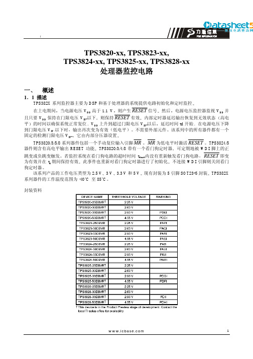
1TPS3820-xx, TPS3823-xx,TPS3824-xx, TPS3825-xx, TPS3828-xx处理器监控电路一 概述1 1 描述TPS382X 系列监控器主要为DSP 和基于处理器的系统提供电路初始化和定时监控在上电期间当电源电压V DD 高于1.1 V 则产生RESET 信号然后电源电压监控器监视V DD 并且只要V DD 保持在门限电压V IT-以下则保持RESET 有效内部定时器延迟输出恢复到无效状态高电平的时间以确保系统正常复位V DD 上升到超过门限电压V IT-以后延迟时间td 开始在电源电压下降到门限电压V IT–以下时输出再次变为有效低电平不需要外部元件该系列中的所有器件都有一个固定的检测门限电压V IT-它由内部分压器设置TPS3820/3/5/8系列器件包括一个手动复位输入引脚MR MR 为低电平时激活RESET TPS3824/5器件则含有高电平输出RESET 功能TPS3820/3/4/8带有一个看门狗定时器可定期地被WDI 脚上的正跳变或负跳变触发若监控系统在看门狗电路的超时时间t t(out)内没有重新触发看门狗电路RESET 即变为有效并在t d 期间保持有效此事件也重新对看门狗定时器进行了初始化不连接WDI 引脚则关闭看门狗定时器该系列产品的工作电压类型为2.5 V 3 V 3.3 V 和5 V 现有封装为5引脚SOT23-5封装TPS382X 系列器件的工作温度范围为–40°C 至85°C封装资料21 2 特点z带有200 ms (TPS3823/4/5/8)或25 ms (TPS3820)固定延迟时间的上电复位发生器z手动复位输入(TPS3820/3/5/8)z推/拉复位(TPS3820/3/4/5)复位(TPS3824)或漏极开路输出(TPS3828)z电源电压监控范围 2.5 V 3 V 3.3 V 和5 V z看门狗定时器(TPS3820/3/4/8)z电源电流为15A 典型值zSOT23-5封装z 温度范围–40°C 至85°C1 3 典型应用z用到DSP 微控制器或微处理器时的应用环境z工业设备z可编程控制z自动化系统z便携式/电池供电设备z智能仪器z无线通信系统z 笔记本/台式计算机典型应用图1 5 功能表1 4 引脚排列图31 6 功能方框图17 时序图二 特性2 1 自然通风工作温度范围内的极限参数*电源电压V DD 见注1 6V 输入电压MR WDI 见注1 –0.3 V 至 (V DD + 0.3V)最低输出电流I OL 5mA 最高输出电流I OH –5mA 输入箝位电流范围I IK (V I < 0或V I > V DD ) ±10mA 输出箝位电流范围I OK (V O < 0或 V O > V DD ) ±10mA4持续总功耗 见额定功耗表自然通风工作温度范围T A –40°C 至85°C 贮存温度范围Tstg –65°C 至150°C 焊接温度 260°C*强度超出所列的极限参数可能导致器件的永久性损坏这些仅仅是极限参数并不意味着在极限条件下或在任何其它超出推荐工作条件所示参数的情况下器件能有效工作延长在极限参数条件下的工作时间会影响器件的可靠性注1所有电压值相对于地额定功耗表22推荐工作条件2 3 在推荐的自然通风工作温度范围内的电特性除非另有规定3为确保门限电压的最佳稳定性应在电源端附近加一个旁路电容器陶瓷0.1F56续前表注4在RESET 被一个P 双向复位引脚激活为低电平时RESET 短路电流为最大上拉电流2 4 定时要求R L = 1 M , C L = 50 pF, T A = 25°C 时2 5 开关特性R L = 1 M , C L = 50 pF, T A = 25°C 时2 6 典型特性78三机械数据注A所有直线尺寸均以毫米为单位B对此图的改变不另行通知C主体部分的尺寸包括模型薄膜或凸出部分声明本资料仅供参考如有不同之处请以相应英文资料为准9。
P89LPC901_902_903中文数据完整手册
3. 定购信息......................................................................................................................................5 3.1 定购选择..............................................................................................................................5
4. 功能框图......................................................................................................................................6 5. 管脚信息......................................................................................................................................7 5.1 管脚配置................................................................................................................................7 5.2 管脚描述................................................................................................................................8 6. 逻辑符号.................................................................................................................................... 11 7. 特殊功能寄存器........................................................................................................................12 8.功能描述......................................................................................................................................20 8.1 增强型 CPU.........................................................................................................................20 8.2 时钟......................................................................................................................................20 8.2.1 时钟定义 .......................................................................................................................20 8.2.2 CPU 时钟(OSCCLK) .................................................................................................21 8.2.3 低频振荡器选项(P89LPC901) ...............................................................................21 8.2.4 中频振荡器选项(P89LPC901) ................................................................................21 8.2.5 高频振荡器选项(P89LPC901) ................................................................................21 8.2.6 时钟输出(P89LPC901) ...........................................................................................21 8.3 片内 RC 振荡器选项 ..........................................................................................................21 8.4 看门狗振荡器选项 ..............................................................................................................22 8.5 外部时钟输入选项(P89LPC901)........................................................................................22 8.6 CPU 时钟(CCLK)唤醒延迟 ...........................................................................................23 8.7 CPU 时钟(CCLK)调整:DIVM 寄存器 .....................................................................23 8.8 低功耗选择 ..........................................................................................................................23 8.9 存储器结构 ..........................................................................................................................23 8.10 数据 RAM 的分配...........................................................................................................23 8.11 中断 ....................................................................................................................................23 8.11.1 外部中断输入 .............................................................................................................24 8.12 I/O 口 ................................................................................................................................25 8.12.1 I/O 口配置 ................................................................................................................25 8.12.2 准双向口输出配置 .....................................................................................................25 8.12.3 开漏输出配置 .............................................................................................................26
TPS3823型电压监控电路
1TPS3823的主要特点和引脚功能TPS3823是TI公司推出的TPS382x系列的电压监控电路,用于对TPS312x系列监控电路的补充,TPS382x系列器件不需要外围电路即可组成监控电路,同时具有看门狗、手动复位、低电平复位等功能。
主要应用于DSP、微处理器和微控制器的监控、工业设备、车载系统、智能仪器仪表和无线通讯系统等领域。
其主要特点如下:●在微处理器上电时,产生固定200ms滞后的低电平复位脉冲信号。
●带手动复位功能,可监控电压为:2.5V、3V、3.3V、5V。
●具有Watchdog电路,该电路的外触发脉冲时间间隔超过1.6s时,将产生一个低电平复位输出。
●供电电压范围:1.1V~5.5V,输出电流15μA(典型值)。
●SOT23-5封装,工作温度范围:-40℃~85℃。
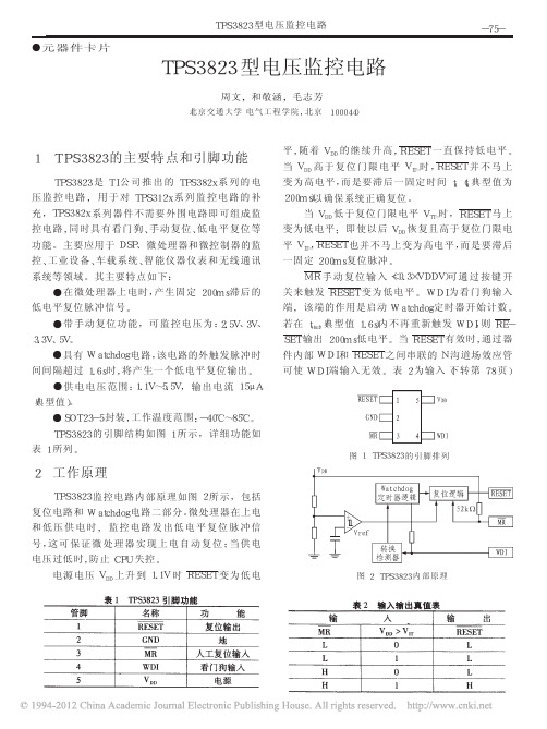
TPS3823的引脚结构如图1所示,详细功能如表1所列。
2工作原理TPS3823监控电路内部原理如图2所示,包括复位电路和Watchdog电路二部分。
微处理器在上电和低压供电时,监控电路发出低电平复位脉冲信号,这可保证微处理器实现上电自动复位;当供电电压过低时,防止CPU失控。
电源电压VDD上升到1.1V时RESET变为低电平,随着VDD的继续升高,RESET一直保持低电平。
当VDD高于复位门限电平VIT-时,RESET并不马上变为高电平,而是要滞后一固定时间td(td典型值为200ms)以确保系统正确复位。
当VDD低于复位门限电平VTT-时,RESET马上变为低电平;即使以后VDD恢复且高于复位门限电平VIT-,RESET也并不马上变为高电平,而是要滞后一固定200ms复位脉冲。
MR手动复位输入(<0.3×VDDV)可通过按键开关来触发RESET变为低电平。
WDI为看门狗输入端,该端的作用是启动Watchdog定时器开始计数。
若在tt(out)(典型值1.6s)内不再重新触发WDI,则RE-SET输出200ms低电平。
第十二章ARM看门狗Watchdog电路

如看门狗初始化程序:
//------------------------------------------------------------------------ // 看门狗初始化
表12-3 看门狗定时器数据寄存器
寄存器名称 WTDAT
地址 0x53000004
读/写状态 R/W
描述 看门狗定时器数据寄存器
复位值 0x8000
表12-4 看门狗定时器数据寄存器WTDAT各位的定义
WTDAT 当前重载值
位
描述
初始状态
[15:0]
看门狗定时器的重载计数器
0x800
表12-5 看门狗定时器/计数器寄存器
factor)
其中, PCLK为系统时钟频率;Prescaler value为预分频值 (值0~255 );Division_ factor为四分频值,可以是16、 32、64或128。
看门狗的定时周期:
T = WTCNT×t_Watchdog
其中WTCNT是看门狗定时器的计数器,它的值表示
该定时器的当前计数值。
寄存器名称 地址 WTCNT 0x53000008
读/写状态
描述
复位值
R/W 看门狗定时器/计数器寄存器 0x8000
表12-6 看门狗定时器/计数器寄存器WTCNT各位的定义
WTCNT 计数器
位
描述
初始状态
[15:0]
看门狗定时器的当前计数器
0x800
12.2 看门狗电路的编程
看门狗电路编程较简单,首先看门狗电路初始化,即
复位芯片tps3823工作原理
复位芯片tps3823工作原理
嘿!今天咱们来聊聊复位芯片tps3823 的工作原理呀!这玩意儿可神奇了呢!
哎呀呀,先来说说这tps3823 到底是干啥的?它呀,就是专门负责保障整个系统稳定运行的一个小能手哇!
那它的工作原理到底是咋样的呢?听我慢慢道来!当系统的电源电压出现异常的时候,比如说突然下降或者波动得厉害,这tps3823 就会立刻警觉起来呢!它就像一个警惕的小卫士,时刻监测着电源的状态呀!一旦发现不对劲,它就会迅速发出复位信号,让系统重新回到正常的状态,这可太重要了呀!
你想想,如果没有它,系统可能就会陷入混乱,各种错误和故障就会接踵而来,那可就糟糕啦!tps3823 内部有一系列精密的电路和检测机制呢。
它能够准确地判断电源电压的变化范围,并且在必要的时候果断采取行动,哇,是不是超级厉害?
而且呀,它对于不同的电源电压和工作环境都有很好的适应性呢!不管是在高温还是低温的环境下,它都能稳定地工作,保障系统的正常运行。
这意味着什么?意味着我们在各种复杂的条件下都能依靠它,不用担心系统会出大问题呀!
还有哦,它的响应速度也是非常快的!一旦电源出现异常,它几乎是瞬间就做出反应,及时发出复位信号。
这就像是在紧急关头,有人能够迅速出手相助,力挽狂澜呢!
怎么样?对这复位芯片tps3823 的工作原理是不是有了更清晰
的了解啦?哎呀呀,有了它,咱们的电子设备才能更稳定、更可靠地工作呀!。
TPS3801K33DCKR中文资料

AVAILABLE OPTIONS
THRESHOLD VOLTAGE Adjustable (Vref = 1.14 V) 1.71 V 2.25 V 2.5 V 2.64 V 2.93 V 2.64 V 2.93 V 4.00 V 4.55 V
TYP DELAY TIME 200 ms 200 ms 200 ms 95 ms 200 ms 200 ms 380 ms 380 ms 25 ms 200 ms
MARKING ARF ARE NJA ARI NPA NWA ASA ARK AVI NSA
ABSOLUTE MAXIMUM RATINGS
over operating free-air temperature range (unless otherwise noted) (1) (2)
Supply voltage, VDD All other pins
parameter
test conditions
min
typ max unit
VDD = 1.6 V to 6 V IOH = -500 µA
VOH High-level output voltage (RESET)
VDD = 3.3 V IOH = -2 mA
VDD = 6 V IOH = -4 mA (1)
min
max
unit
TPS3801J25, TPS3801L30,
TPS3801K33, TPS3801I50,
2
6
TPS3801T50
V
All other devices
1.6
4
0 0.7×VDD
VDD+0.3
0.3×VDD 100
复旦大学模拟电路二级运放实例

3.6.1 定义 ........................................................................................................ 16 3.6.2 两级运放的 CMRR .................................................................................. 17 3.7 电源抑制比(PSRR) ................................................................................ 18 3.7.1 定义 ........................................................................................................ 18 3.7.2 两级运放的 PSRR ................................................................................... 19 3.8 转换速率(Slew Rate) ............................................................................. 21 3.8.1 定义 ........................................................................................................ 21 3.8.2 两级放大器的 Slew Rate ......................................................................... 22 3.8.3 单位增益带宽 GBW 和压摆率 SR............................................................ 23 3.9 噪声 ............................................................................................................ 24 3.9.1 低频噪声 ................................................................................................. 24
TPS54331中文资料

TPS54331【用途】电源管理/DC-DC转换电路【性能参数】采用双列贴片8引脚封装。
用于以3.5V 至28V 的输入电压提供3A 的输出电流低至0.8V 的可调输出电压。
开关频率被内部设置为570kHz(hertz)赫兹的额定频率。
提供可调节慢启动和欠电压锁定输入。
TPS54331EVM-232 输入电压的最大绝对值是30V。
是一款采用Natural Interleaving技术的双相位功率因子校正(PFC)控制器以及最新SWIFT的DC/DC电源管理转换器。
技术特征:◆Eco-mode:轻载情况下自动进入跳周期模式,可以提高轻载条件下的系统效率。
跳周期模式并不是在TPS54331中首次应用,也不是TI首次应用,它是一种被广泛应用的成熟技术,不过TI为其借用了一个好听的名字,Eco-mode意为经济模式或者节能模式,在显示器、电视机、UPS、投影机等用电设备的说明书中,这个名词也常见,TI则将这个名词用于器件而不是整机或者单元电路中,并为之注册了商标:◆SWIFT:TI专门为其DC-DC电源管理器件开发的软件设计工具,借用SWIFT名称并申请了商标;有两种含义,一种是指SocietyWorldwideInterbankFinanciaLTElecommunation(环球同业银行金融电讯协会)的缩写,该协会的成员银行都有自己特定的SWIFT代码,即SWIFTCODE (代码),它相当于各个银行的身份证号,在该协会内是唯一的,其作用是减少各银行间业务错误的发生几率,各国知名银行,也包括国内的几家银行都是该协会的成员;作为单独一个词,SWIFT含义是迅速的。
◆待机模式的电流消耗约lμA;◆570kHz固定开关频率:◆逐周期限流保护,过热关断,输出级晶体管过压保护,可编程的输入欠压锁定,软启动时间可设定及至关断,折频保护。
折频保护的原理是在电路启动期间和电流过载时降低开关频率以降低电感中的冲击电流,这种保护机理有“釜底抽薪”之妙,已经被广泛应用,常见的中文译名是“频率折叠”或者“频率折返”(从易于理解的角度来说,这些译名值得商榷)。
TPS3828中文资料

PACKAGING INFORMATIONOrderable DeviceStatus (1)Package Type Package Drawing Pins Package Qty Eco Plan (2)Lead/Ball Finish MSL Peak Temp (3)TPS3820-33DBVR ACTIVE SOT-23DBV 53000Green (RoHS &no Sb/Br)CU NIPDAU Level-1-260C-UNLIM TPS3820-33DBVRG4ACTIVE SOT-23DBV 53000Green (RoHS &no Sb/Br)CU NIPDAU Level-1-260C-UNLIM TPS3820-33DBVT ACTIVE SOT-23DBV 5250Green (RoHS &no Sb/Br)CU NIPDAU Level-2-260C-1YEAR TPS3820-33DBVTG4ACTIVE SOT-23DBV 5250Green (RoHS &no Sb/Br)CU NIPDAU Level-2-260C-1YEAR TPS3820-50DBVR ACTIVE SOT-23DBV 53000Green (RoHS &no Sb/Br)CU NIPDAU Level-2-260C-1YEAR TPS3820-50DBVRG4ACTIVE SOT-23DBV 53000Green (RoHS &no Sb/Br)CU NIPDAU Level-2-260C-1YEAR TPS3820-50DBVT ACTIVE SOT-23DBV 5250Green (RoHS &no Sb/Br)CU NIPDAU Level-2-260C-1YEAR TPS3820-50DBVTG4ACTIVE SOT-23DBV 5250Green (RoHS &no Sb/Br)CU NIPDAU Level-2-260C-1YEAR TPS3823-25DBVR ACTIVE SOT-23DBV 53000Green (RoHS &no Sb/Br)CU NIPDAU Level-2-260C-1YEAR TPS3823-25DBVRG4ACTIVE SOT-23DBV 53000Green (RoHS &no Sb/Br)CU NIPDAU Level-2-260C-1YEAR TPS3823-25DBVT ACTIVE SOT-23DBV 5250Green (RoHS &no Sb/Br)CU NIPDAU Level-2-260C-1YEAR TPS3823-30DBVR ACTIVE SOT-23DBV 53000Green (RoHS &no Sb/Br)CU NIPDAU Level-2-260C-1YEAR TPS3823-30DBVRG4ACTIVE SOT-23DBV 53000Green (RoHS &no Sb/Br)CU NIPDAU Level-2-260C-1YEAR TPS3823-30DBVT ACTIVE SOT-23DBV 5250Green (RoHS &no Sb/Br)CU NIPDAU Level-2-260C-1YEAR TPS3823-30DBVTG4ACTIVE SOT-23DBV 5250Green (RoHS &no Sb/Br)CU NIPDAU Level-2-260C-1YEAR TPS3823-33DBVR ACTIVE SOT-23DBV 53000Green (RoHS &no Sb/Br)CU NIPDAU Level-2-260C-1YEAR TPS3823-33DBVRG4ACTIVE SOT-23DBV 53000Green (RoHS &no Sb/Br)CU NIPDAU Level-2-260C-1YEAR TPS3823-33DBVT ACTIVE SOT-23DBV 5250Green (RoHS &no Sb/Br)CU NIPDAU Level-2-260C-1YEAR TPS3823-33DBVTG4ACTIVE SOT-23DBV 5250Green (RoHS &no Sb/Br)CU NIPDAU Level-2-260C-1YEAR TPS3823-50DBVR ACTIVE SOT-23DBV 53000Green (RoHS &no Sb/Br)CU NIPDAU Level-2-260C-1YEAR TPS3823-50DBVRG4ACTIVE SOT-23DBV 53000Green (RoHS &no Sb/Br)CU NIPDAU Level-2-260C-1YEAR TPS3823-50DBVT ACTIVE SOT-23DBV 5250Green (RoHS &no Sb/Br)CU NIPDAU Level-2-260C-1YEAR TPS3823-50DBVTG4ACTIVE SOT-23DBV 5250Green (RoHS &no Sb/Br)CU NIPDAU Level-2-260C-1YEAR TPS3824-25DBVR ACTIVE SOT-23DBV 53000Green (RoHS &no Sb/Br)CU NIPDAU Level-2-260C-1YEAR TPS3824-25DBVRG4ACTIVESOT-23DBV53000Green (RoHS &no Sb/Br)CU NIPDAULevel-2-260C-1YEARPACKAGE OPTION ADDENDUM4-Mar-2005Addendum-Page 1元器件交易网Orderable Device Status(1)PackageType PackageDrawingPins PackageQtyEco Plan(2)Lead/Ball Finish MSL Peak Temp(3)TPS3824-25DBVT ACTIVE SOT-23DBV5250Green(RoHS&no Sb/Br)CU NIPDAU Level-2-260C-1YEARTPS3824-30DBVR ACTIVE SOT-23DBV53000Green(RoHS&no Sb/Br)CU NIPDAU Level-2-260C-1YEARTPS3824-30DBVRG4ACTIVE SOT-23DBV53000Green(RoHS&no Sb/Br)CU NIPDAU Level-2-260C-1YEARTPS3824-30DBVT ACTIVE SOT-23DBV5250Green(RoHS&no Sb/Br)CU NIPDAU Level-2-260C-1YEARTPS3824-30DBVTG4ACTIVE SOT-23DBV5250Green(RoHS&no Sb/Br)CU NIPDAU Level-2-260C-1YEARTPS3824-33DBVR ACTIVE SOT-23DBV53000Green(RoHS&no Sb/Br)CU NIPDAU Level-2-260C-1YEARTPS3824-33DBVRG4ACTIVE SOT-23DBV53000Green(RoHS&no Sb/Br)CU NIPDAU Level-2-260C-1YEARTPS3824-33DBVT ACTIVE SOT-23DBV5250Green(RoHS&no Sb/Br)CU NIPDAU Level-2-260C-1YEARTPS3824-50DBVR ACTIVE SOT-23DBV53000Green(RoHS&no Sb/Br)CU NIPDAU Level-2-260C-1YEARTPS3824-50DBVRG4ACTIVE SOT-23DBV53000Green(RoHS&no Sb/Br)CU NIPDAU Level-2-260C-1YEARTPS3824-50DBVT ACTIVE SOT-23DBV5250Green(RoHS&no Sb/Br)CU NIPDAU Level-2-260C-1YEARTPS3824-50DBVTG4ACTIVE SOT-23DBV5250Green(RoHS&no Sb/Br)CU NIPDAU Level-2-260C-1YEARTPS3825-33DBVR ACTIVE SOT-23DBV53000Green(RoHS&no Sb/Br)CU NIPDAU Level-2-260C-1YEARTPS3825-33DBVRG4ACTIVE SOT-23DBV53000Green(RoHS&no Sb/Br)CU NIPDAU Level-2-260C-1YEARTPS3825-33DBVT ACTIVE SOT-23DBV5250Green(RoHS&no Sb/Br)CU NIPDAU Level-2-260C-1YEARTPS3825-33DBVTG4ACTIVE SOT-23DBV5250Green(RoHS&no Sb/Br)CU NIPDAU Level-2-260C-1YEARTPS3825-50DBVR ACTIVE SOT-23DBV53000Green(RoHS&no Sb/Br)CU NIPDAU Level-2-260C-1YEARTPS3825-50DBVRG4ACTIVE SOT-23DBV53000Green(RoHS&no Sb/Br)CU NIPDAU Level-2-260C-1YEARTPS3825-50DBVT ACTIVE SOT-23DBV5250Green(RoHS&no Sb/Br)CU NIPDAU Level-2-260C-1YEARTPS3825-50DBVTG4ACTIVE SOT-23DBV5250Green(RoHS&no Sb/Br)CU NIPDAU Level-2-260C-1YEARTPS3828-33DBVR ACTIVE SOT-23DBV53000Green(RoHS&no Sb/Br)CU NIPDAU Level-2-260C-1YEARTPS3828-33DBVRG4ACTIVE SOT-23DBV53000Green(RoHS&no Sb/Br)CU NIPDAU Level-1-260C-UNLIMTPS3828-33DBVT ACTIVE SOT-23DBV5250Green(RoHS&no Sb/Br)CU NIPDAU Level-2-260C-1YEARTPS3828-33DBVTG4ACTIVE SOT-23DBV5250Green(RoHS&no Sb/Br)CU NIPDAU Level-2-260C-1YEARTPS3828-50DBVR ACTIVE SOT-23DBV53000Green(RoHS&no Sb/Br)CU NIPDAU Level-2-260C-1YEARTPS3828-50DBVRG4ACTIVE SOT-23DBV53000Green(RoHS&no Sb/Br)CU NIPDAU Level-2-260C-1YEAROrderable Device Status(1)PackageType PackageDrawingPins PackageQtyEco Plan(2)Lead/Ball Finish MSL Peak Temp(3)TPS3828-50DBVT ACTIVE SOT-23DBV5250Green(RoHS&no Sb/Br)CU NIPDAU Level-2-260C-1YEARTPS3828-50DBVTG4ACTIVE SOT-23DBV5250Green(RoHS&no Sb/Br)CU NIPDAU Level-2-260C-1YEAR(1)The marketing status values are defined as follows:ACTIVE:Product device recommended for new designs.LIFEBUY:TI has announced that the device will be discontinued,and a lifetime-buy period is in effect.NRND:Not recommended for new designs.Device is in production to support existing customers,but TI does not recommend using this part in a new design.PREVIEW:Device has been announced but is not in production.Samples may or may not be available.OBSOLETE:TI has discontinued the production of the device.(2)Eco Plan-May not be currently available-please check /productcontent for the latest availability information and additional product content details.None:Not yet available Lead(Pb-Free).Pb-Free(RoHS):TI's terms"Lead-Free"or"Pb-Free"mean semiconductor products that are compatible with the current RoHS requirements for all6substances,including the requirement that lead not exceed0.1%by weight in homogeneous materials.Where designed to be soldered at high temperatures,TI Pb-Free products are suitable for use in specified lead-free processes.Green(RoHS&no Sb/Br):TI defines"Green"to mean"Pb-Free"and in addition,uses package materials that do not contain halogens, including bromine(Br)or antimony(Sb)above0.1%of total product weight.(3)MSL,Peak Temp.--The Moisture Sensitivity Level rating according to the JEDECindustry standard classifications,and peak solder temperature.Important Information and Disclaimer:The information provided on this page represents TI's knowledge and belief as of the date that it is provided.TI bases its knowledge and belief on information provided by third parties,and makes no representation or warranty as to the accuracy of such information.Efforts are underway to better integrate information from third parties.TI has taken and continues to take reasonable steps to provide representative and accurate information but may not have conducted destructive testing or chemical analysis on incoming materials and chemicals.TI and TI suppliers consider certain information to be proprietary,and thus CAS numbers and other limited information may not be available for release.In no event shall TI's liability arising out of such information exceed the total purchase price of the TI part(s)at issue in this document sold by TI to Customer on an annual basis.IMPORTANT NOTICETexas Instruments Incorporated and its subsidiaries (TI) reserve the right to make corrections, modifications, enhancements, improvements, and other changes to its products and services at any time and to discontinue any product or service without notice. Customers should obtain the latest relevant information before placing orders and should verify that such information is current and complete. All products are sold subject to TI’s terms and conditions of sale supplied at the time of order acknowledgment.TI warrants performance of its hardware products to the specifications applicable at the time of sale in accordance with TI’s standard warranty. T esting and other quality control techniques are used to the extent TI deems necessary to support this warranty. Except where mandated by government requirements, testing of all parameters of each product is not necessarily performed.TI assumes no liability for applications assistance or customer product design. Customers are responsible for their products and applications using TI components. T o minimize the risks associated with customer products and applications, customers should provide adequate design and operating safeguards.TI does not warrant or represent that any license, either express or implied, is granted under any TI patent right, copyright, mask work right, or other TI intellectual property right relating to any combination, machine, or process in which TI products or services are used. Information published by TI regarding third-party products or services does not constitute a license from TI to use such products or services or a warranty or endorsement thereof. Use of such information may require a license from a third party under the patents or other intellectual property of the third party, or a license from TI under the patents or other intellectual property of TI.Reproduction of information in TI data books or data sheets is permissible only if reproduction is without alteration and is accompanied by all associated warranties, conditions, limitations, and notices. Reproduction of this information with alteration is an unfair and deceptive business practice. TI is not responsible or liable for such altered documentation.Resale of TI products or services with statements different from or beyond the parameters stated by TI for that product or service voids all express and any implied warranties for the associated TI product or service and is an unfair and deceptive business practice. TI is not responsible or liable for any such statements. Following are URLs where you can obtain information on other Texas Instruments products and application solutions:Products ApplicationsAmplifiers Audio /audioData Converters Automotive /automotiveDSP Broadband /broadbandInterface Digital Control /digitalcontrolLogic Military /militaryPower Mgmt Optical Networking /opticalnetwork Microcontrollers Security /securityTelephony /telephonyVideo & Imaging /videoWireless /wirelessMailing Address:Texas InstrumentsPost Office Box 655303 Dallas, Texas 75265Copyright 2005, Texas Instruments Incorporated。
看门狗电路基本原理及屏蔽方法

看门狗电路基本原理及屏蔽⽅法⼀、定义 看门狗,⼜叫watchdog timer,是⼀个定时器电路,⼀般有⼀个输⼊,叫喂狗(kicking the dog/service the dog),⼀个输出到MCU的RST端,MCU正常⼯作的时候,每隔⼀段时间输出⼀个信号到喂狗端,给 WDT清零,如果超过规定的时间不喂狗(⼀般在程序跑飞时),WDT定时超过,就会给出⼀个复位信号到MCU,使MCU复位。
防⽌MCU死机. 看门狗的作⽤就是防⽌程序发⽣死循环,或者说程序跑飞。
⼆、基本原理: 看门狗是⼀种监控系统的运⾏状况的⼿段,通过软硬件结合的⽅式实现对系统运⾏状况的监控。
稳定运⾏的软件会在执⾏完特定指令后进⾏喂狗,若在⼀定周期内看门狗没有收到来⾃软件的喂狗信号,则认为系统故障,会进⼊中断处理程序或强制系统复位。
系统上电后根据不同的⼯作模式可以选择使能看门狗的时机,若看门狗被使能则计数器开始计数,如果在设定的时间内没有及时喂狗则会发⽣看门狗超时。
看门狗主要由寄存器、计数器和狗叫模块构成:通过寄存器对看门狗进⾏基本设置,计数器计算狗叫时间,狗叫模块决定看门狗超时后发出的中断或复位⽅式。
三、分类:3.1硬件看门狗: 硬件看门狗是利⽤了⼀个定时器,来监控主程序的运⾏,也就是说在主程序的运⾏过程中,我们要在定时时间到之前对定时器进⾏复位。
如果出现死循环,或者说PC指针不能回来,那么定时时间到后就会使单⽚机复位。
常⽤的WDT芯⽚如MAX813,5045,IMP 813等。
3.2软件看门狗: ⽽在某些情况下,也会采⽤纯软件的⽅法来设置看门狗,如在单⽚机系统中,利⽤闲置的定时器/计数器就可以设计⼀个软件看门狗。
具体实现步骤如下: ⾸先,在初始化程序中设置定时器/计数器的⽅式以控制寄存器(TMOD)和定时时间的初值,并且打开中断。
然后,根据定时器的时间,在主程序中按⼀定的时间间隔插⼈复位定时器的指令(喂狗),两条喂狗指令之间的时间间隔可以根据系统时钟与指令周期计算出来,⽽且该时间周期应该⼩于定时器的定时时间。
tps3823-33

ESD damage can range from subtle performance degradation to complete device failure. Precision integrated circuits may be more susceptible to damage because very small parametric changes could cause the device not to meet its published specifications.ABSOLUTE MAXIMUM RATINGSOver operating free-air temperature range, unless otherwise noted.Supply voltage, VRESETMaximum low output current, IMaximum high output current, IPACKAGING INFORMATIONOrderableDevice Status (1)Package Type Package Drawing Pins Package Qty Eco Plan (2)Lead/Ball Finish MSL Peak Temp (3)TPS3820-33DBVR ACTIVE SOT-23DBV 53000Green (RoHS &no Sb/Br)CU NIPDAU Level-1-260C-UNLIM TPS3820-33DBVRG4ACTIVE SOT-23DBV 53000Green (RoHS &no Sb/Br)CU NIPDAU Level-1-260C-UNLIM TPS3820-33DBVT ACTIVE SOT-23DBV 5250Green (RoHS &no Sb/Br)CU NIPDAU Level-1-260C-UNLIM TPS3820-33DBVTG4ACTIVE SOT-23DBV 5250Green (RoHS &no Sb/Br)CU NIPDAU Level-1-260C-UNLIM TPS3820-50DBVR ACTIVE SOT-23DBV 53000Green (RoHS &no Sb/Br)CU NIPDAU Level-1-260C-UNLIM TPS3820-50DBVRG4ACTIVE SOT-23DBV 53000Green (RoHS &no Sb/Br)CU NIPDAU Level-1-260C-UNLIM TPS3820-50DBVT ACTIVE SOT-23DBV 5250Green (RoHS &no Sb/Br)CU NIPDAU Level-1-260C-UNLIM TPS3820-50DBVTG4ACTIVE SOT-23DBV 5250Green (RoHS &no Sb/Br)CU NIPDAU Level-1-260C-UNLIM TPS3823-25DBVR ACTIVE SOT-23DBV 53000Green (RoHS &no Sb/Br)CU NIPDAU Level-1-260C-UNLIM TPS3823-25DBVRG4ACTIVE SOT-23DBV 53000Green (RoHS &no Sb/Br)CU NIPDAU Level-1-260C-UNLIM TPS3823-25DBVT ACTIVE SOT-23DBV 5250Green (RoHS &no Sb/Br)CU NIPDAU Level-1-260C-UNLIM TPS3823-25DBVTG4ACTIVE SOT-23DBV 5250Green (RoHS &no Sb/Br)CU NIPDAU Level-1-260C-UNLIM TPS3823-30DBVR ACTIVE SOT-23DBV 53000Green (RoHS &no Sb/Br)CU NIPDAU Level-1-260C-UNLIM TPS3823-30DBVRG4ACTIVE SOT-23DBV 53000Green (RoHS &no Sb/Br)CU NIPDAU Level-1-260C-UNLIM TPS3823-30DBVT ACTIVE SOT-23DBV 5250Green (RoHS &no Sb/Br)CU NIPDAU Level-1-260C-UNLIM TPS3823-30DBVTG4ACTIVE SOT-23DBV 5250Green (RoHS &no Sb/Br)CU NIPDAU Level-1-260C-UNLIM TPS3823-33DBVR ACTIVE SOT-23DBV 53000Green (RoHS &no Sb/Br)CU NIPDAU Level-1-260C-UNLIM TPS3823-33DBVRG4ACTIVE SOT-23DBV 53000Green (RoHS &no Sb/Br)CU NIPDAU Level-1-260C-UNLIM TPS3823-33DBVT ACTIVE SOT-23DBV 5250Green (RoHS &no Sb/Br)CU NIPDAU Level-1-260C-UNLIM TPS3823-33DBVTG4ACTIVE SOT-23DBV 5250Green (RoHS &no Sb/Br)CU NIPDAU Level-1-260C-UNLIM TPS3823-50DBVR ACTIVE SOT-23DBV 53000Green (RoHS &no Sb/Br)CU NIPDAU Level-1-260C-UNLIM TPS3823-50DBVRG4ACTIVE SOT-23DBV 53000Green (RoHS &no Sb/Br)CU NIPDAU Level-1-260C-UNLIM TPS3823-50DBVT ACTIVE SOT-23DBV 5250Green (RoHS &no Sb/Br)CU NIPDAU Level-1-260C-UNLIM TPS3823-50DBVTG4ACTIVE SOT-23DBV 5250Green (RoHS &no Sb/Br)CU NIPDAU Level-1-260C-UNLIM TPS3824-25DBVRACTIVESOT-23DBV53000Green (RoHS &no Sb/Br)CU NIPDAULevel-1-260C-UNLIMPACKAGE OPTION ADDENDUM18-Sep-2008Addendum-Page 1Orderable Device Status(1)PackageType PackageDrawingPins PackageQtyEco Plan(2)Lead/Ball Finish MSL Peak Temp(3)TPS3824-25DBVRG4ACTIVE SOT-23DBV53000Green(RoHS&no Sb/Br)CU NIPDAU Level-1-260C-UNLIMTPS3824-25DBVT ACTIVE SOT-23DBV5250Green(RoHS&no Sb/Br)CU NIPDAU Level-1-260C-UNLIMTPS3824-25DBVTG4ACTIVE SOT-23DBV5250Green(RoHS&no Sb/Br)CU NIPDAU Level-1-260C-UNLIMTPS3824-30DBVR ACTIVE SOT-23DBV53000Green(RoHS&no Sb/Br)CU NIPDAU Level-1-260C-UNLIMTPS3824-30DBVRG4ACTIVE SOT-23DBV53000Green(RoHS&no Sb/Br)CU NIPDAU Level-1-260C-UNLIMTPS3824-30DBVT ACTIVE SOT-23DBV5250Green(RoHS&no Sb/Br)CU NIPDAU Level-1-260C-UNLIMTPS3824-30DBVTG4ACTIVE SOT-23DBV5250Green(RoHS&no Sb/Br)CU NIPDAU Level-1-260C-UNLIMTPS3824-33DBVR ACTIVE SOT-23DBV53000Green(RoHS&no Sb/Br)CU NIPDAU Level-1-260C-UNLIMTPS3824-33DBVRG4ACTIVE SOT-23DBV53000Green(RoHS&no Sb/Br)CU NIPDAU Level-1-260C-UNLIMTPS3824-33DBVT ACTIVE SOT-23DBV5250Green(RoHS&no Sb/Br)CU NIPDAU Level-1-260C-UNLIMTPS3824-33DBVTG4ACTIVE SOT-23DBV5250Green(RoHS&no Sb/Br)CU NIPDAU Level-1-260C-UNLIMTPS3824-50DBVR ACTIVE SOT-23DBV53000Green(RoHS&no Sb/Br)CU NIPDAU Level-1-260C-UNLIMTPS3824-50DBVRG4ACTIVE SOT-23DBV53000Green(RoHS&no Sb/Br)CU NIPDAU Level-1-260C-UNLIMTPS3824-50DBVT ACTIVE SOT-23DBV5250Green(RoHS&no Sb/Br)CU NIPDAU Level-1-260C-UNLIMTPS3824-50DBVTG4ACTIVE SOT-23DBV5250Green(RoHS&no Sb/Br)CU NIPDAU Level-1-260C-UNLIMTPS3825-33DBVR ACTIVE SOT-23DBV53000Green(RoHS&no Sb/Br)CU NIPDAU Level-1-260C-UNLIMTPS3825-33DBVRG4ACTIVE SOT-23DBV53000Green(RoHS&no Sb/Br)CU NIPDAU Level-1-260C-UNLIMTPS3825-33DBVT ACTIVE SOT-23DBV5250Green(RoHS&no Sb/Br)CU NIPDAU Level-1-260C-UNLIMTPS3825-33DBVTG4ACTIVE SOT-23DBV5250Green(RoHS&no Sb/Br)CU NIPDAU Level-1-260C-UNLIMTPS3825-50DBVR ACTIVE SOT-23DBV53000Green(RoHS&no Sb/Br)CU NIPDAU Level-1-260C-UNLIMTPS3825-50DBVRG4ACTIVE SOT-23DBV53000Green(RoHS&no Sb/Br)CU NIPDAU Level-1-260C-UNLIMTPS3825-50DBVT ACTIVE SOT-23DBV5250Green(RoHS&no Sb/Br)CU NIPDAU Level-1-260C-UNLIMTPS3825-50DBVTG4ACTIVE SOT-23DBV5250Green(RoHS&no Sb/Br)CU NIPDAU Level-1-260C-UNLIMTPS3828-33DBVR ACTIVE SOT-23DBV53000Green(RoHS&no Sb/Br)CU NIPDAU Level-1-260C-UNLIMTPS3828-33DBVRG4ACTIVE SOT-23DBV53000Green(RoHS&no Sb/Br)CU NIPDAU Level-1-260C-UNLIMTPS3828-33DBVT ACTIVE SOT-23DBV5250Green(RoHS&no Sb/Br)CU NIPDAU Level-1-260C-UNLIMOrderable Device Status(1)PackageType PackageDrawingPins PackageQtyEco Plan(2)Lead/Ball Finish MSL Peak Temp(3)TPS3828-33DBVTG4ACTIVE SOT-23DBV5250Green(RoHS&no Sb/Br)CU NIPDAU Level-1-260C-UNLIMTPS3828-50DBVR ACTIVE SOT-23DBV53000Green(RoHS&no Sb/Br)CU NIPDAU Level-1-260C-UNLIMTPS3828-50DBVRG4ACTIVE SOT-23DBV53000Green(RoHS&no Sb/Br)CU NIPDAU Level-1-260C-UNLIMTPS3828-50DBVT ACTIVE SOT-23DBV5250Green(RoHS&no Sb/Br)CU NIPDAU Level-1-260C-UNLIMTPS3828-50DBVTG4ACTIVE SOT-23DBV5250Green(RoHS&no Sb/Br)CU NIPDAU Level-1-260C-UNLIM(1)The marketing status values are defined as follows:ACTIVE:Product device recommended for new designs.LIFEBUY:TI has announced that the device will be discontinued,and a lifetime-buy period is in effect.NRND:Not recommended for new designs.Device is in production to support existing customers,but TI does not recommend using this part ina new design.PREVIEW:Device has been announced but is not in production.Samples may or may not be available.OBSOLETE:TI has discontinued the production of the device.(2)Eco Plan-The planned eco-friendly classification:Pb-Free(RoHS),Pb-Free(RoHS Exempt),or Green(RoHS&no Sb/Br)-please check /productcontent for the latest availability information and additional product content details.TBD:The Pb-Free/Green conversion plan has not been defined.Pb-Free(RoHS):TI's terms"Lead-Free"or"Pb-Free"mean semiconductor products that are compatible with the current RoHS requirements for all6substances,including the requirement that lead not exceed0.1%by weight in homogeneous materials.Where designed to be solderedat high temperatures,TI Pb-Free products are suitable for use in specified lead-free processes.Pb-Free(RoHS Exempt):This component has a RoHS exemption for either1)lead-based flip-chip solder bumps used between the die and package,or2)lead-based die adhesive used between the die and leadframe.The component is otherwise considered Pb-Free(RoHS compatible)as defined above.Green(RoHS&no Sb/Br):TI defines"Green"to mean Pb-Free(RoHS compatible),and free of Bromine(Br)and Antimony(Sb)based flame retardants(Br or Sb do not exceed0.1%by weight in homogeneous material)(3)MSL,Peak Temp.--The Moisture Sensitivity Level rating according to the JEDEC industry standard classifications,and peak solder temperature.Important Information and Disclaimer:The information provided on this page represents TI's knowledge and belief as of the date that it is provided.TI bases its knowledge and belief on information provided by third parties,and makes no representation or warranty as to the accuracy of such information.Efforts are underway to better integrate information from third parties.TI has taken and continues to take reasonable steps to provide representative and accurate information but may not have conducted destructive testing or chemical analysis on incoming materials and chemicals.TI and TI suppliers consider certain information to be proprietary,and thus CAS numbers and other limited information may not be available for release.In no event shall TI's liability arising out of such information exceed the total purchase price of the TI part(s)at issue in this document sold by TIto Customer on an annual basis.OTHER QUALIFIED VERSIONS OF TPS3820-33,TPS3820-50,TPS3823-25,TPS3823-30,TPS3823-33,TPS3823-50,TPS3824-25, TPS3824-30,TPS3824-33,TPS3824-50,TPS3825-33,TPS3825-50,TPS3828-33,TPS3828-50:•Automotive:TPS3820-33-Q1,TPS3820-50-Q1,TPS3823-25-Q1,TPS3823-30-Q1,TPS3823-33-Q1,TPS3823-50-Q1,TPS3824-25-Q1, TPS3824-30-Q1,TPS3824-33-Q1,TPS3824-50-Q1,TPS3825-33-Q1,TPS3825-50-Q1,TPS3828-33-Q1,TPS3828-50-Q1NOTE:Qualified Version Definitions:•Automotive-Q100devices qualified for high-reliability automotive applications targeting zero defectsTAPE AND REEL INFORMATION*All dimensions are nominal Device Package Type Package DrawingPinsSPQ Reel Diameter (mm)Reel Width W1(mm)A0(mm)B0(mm)K0(mm)P1(mm)W (mm)Pin1Quadrant TPS3820-33DBVR SOT-23DBV 53000179.08.4 3.2 3.2 1.4 4.08.0Q3TPS3820-33DBVR SOT-23DBV 53000180.09.0 3.15 3.2 1.4 4.08.0Q3TPS3820-33DBVT SOT-23DBV 5250179.08.4 3.2 3.2 1.4 4.08.0Q3TPS3820-33DBVT SOT-23DBV 5250180.09.0 3.15 3.2 1.4 4.08.0Q3TPS3820-50DBVR SOT-23DBV 53000179.08.4 3.2 3.2 1.4 4.08.0Q3TPS3820-50DBVT SOT-23DBV 5250179.08.4 3.2 3.2 1.4 4.08.0Q3TPS3823-25DBVR SOT-23DBV 53000179.08.4 3.2 3.2 1.4 4.08.0Q3TPS3823-25DBVR SOT-23DBV 53000180.09.0 3.15 3.2 1.4 4.08.0Q3TPS3823-25DBVT SOT-23DBV 5250179.08.4 3.2 3.2 1.4 4.08.0Q3TPS3823-30DBVR SOT-23DBV 53000178.09.0 3.23 3.17 1.37 4.08.0Q3TPS3823-30DBVT SOT-23DBV 5250178.09.0 3.23 3.17 1.37 4.08.0Q3TPS3823-33DBVR SOT-23DBV 53000178.09.0 3.23 3.17 1.37 4.08.0Q3TPS3823-33DBVT SOT-23DBV 5250178.09.0 3.23 3.17 1.37 4.08.0Q3TPS3823-50DBVR SOT-23DBV 53000179.08.4 3.2 3.2 1.4 4.08.0Q3TPS3823-50DBVR SOT-23DBV 53000178.09.0 3.23 3.17 1.37 4.08.0Q3TPS3823-50DBVT SOT-23DBV 5250179.08.4 3.2 3.2 1.4 4.08.0Q3TPS3823-50DBVT SOT-23DBV 5250178.09.0 3.23 3.17 1.37 4.08.0Q3TPS3824-25DBVR SOT-23DBV 53000179.08.4 3.2 3.2 1.4 4.08.0Q3Device PackageType PackageDrawingPins SPQ ReelDiameter(mm)ReelWidthW1(mm)A0(mm)B0(mm)K0(mm)P1(mm)W(mm)Pin1QuadrantTPS3824-25DBVT SOT-23DBV5250179.08.4 3.2 3.2 1.4 4.08.0Q3 TPS3824-30DBVR SOT-23DBV53000179.08.4 3.2 3.2 1.4 4.08.0Q3 TPS3824-30DBVT SOT-23DBV5250179.08.4 3.2 3.2 1.4 4.08.0Q3 TPS3824-33DBVR SOT-23DBV53000179.08.4 3.2 3.2 1.4 4.08.0Q3 TPS3824-33DBVR SOT-23DBV53000178.09.0 3.23 3.17 1.37 4.08.0Q3 TPS3824-33DBVT SOT-23DBV5250179.08.4 3.2 3.2 1.4 4.08.0Q3 TPS3824-33DBVT SOT-23DBV5250178.09.0 3.23 3.17 1.37 4.08.0Q3 TPS3824-50DBVR SOT-23DBV53000178.09.0 3.23 3.17 1.37 4.08.0Q3 TPS3824-50DBVT SOT-23DBV5250178.09.0 3.23 3.17 1.37 4.08.0Q3 TPS3825-33DBVR SOT-23DBV53000178.09.0 3.23 3.17 1.37 4.08.0Q3 TPS3825-50DBVR SOT-23DBV53000180.09.0 3.15 3.2 1.4 4.08.0Q3 TPS3825-50DBVR SOT-23DBV53000179.08.4 3.2 3.2 1.4 4.08.0Q3 TPS3825-50DBVT SOT-23DBV5250180.09.0 3.15 3.2 1.4 4.08.0Q3 TPS3825-50DBVT SOT-23DBV5250179.08.4 3.2 3.2 1.4 4.08.0Q3 TPS3828-33DBVT SOT-23DBV5250178.09.0 3.23 3.17 1.37 4.08.0Q3 TPS3828-50DBVR SOT-23DBV53000179.08.4 3.2 3.2 1.4 4.08.0Q3 TPS3828-50DBVT SOT-23DBV5250179.08.4 3.2 3.2 1.4 4.08.0Q3*All dimensions are nominalDevice Package Type Package Drawing Pins SPQ Length(mm)Width(mm)Height(mm) TPS3820-33DBVR SOT-23DBV53000203.0203.035.0 TPS3820-33DBVR SOT-23DBV53000182.0182.020.0 TPS3820-33DBVT SOT-23DBV5250203.0203.035.0 TPS3820-33DBVT SOT-23DBV5250182.0182.020.0 TPS3820-50DBVR SOT-23DBV53000203.0203.035.0 TPS3820-50DBVT SOT-23DBV5250203.0203.035.0 TPS3823-25DBVR SOT-23DBV53000203.0203.035.0 TPS3823-25DBVR SOT-23DBV53000182.0182.020.0 TPS3823-25DBVT SOT-23DBV5250203.0203.035.0 TPS3823-30DBVR SOT-23DBV53000180.0180.018.0 TPS3823-30DBVT SOT-23DBV5250180.0180.018.0 TPS3823-33DBVR SOT-23DBV53000180.0180.018.0 TPS3823-33DBVT SOT-23DBV5250180.0180.018.0 TPS3823-50DBVR SOT-23DBV53000203.0203.035.0 TPS3823-50DBVR SOT-23DBV53000180.0180.018.0 TPS3823-50DBVT SOT-23DBV5250203.0203.035.0 TPS3823-50DBVT SOT-23DBV5250180.0180.018.0 TPS3824-25DBVR SOT-23DBV53000203.0203.035.0 TPS3824-25DBVT SOT-23DBV5250203.0203.035.0 TPS3824-30DBVR SOT-23DBV53000203.0203.035.0 TPS3824-30DBVT SOT-23DBV5250203.0203.035.0 TPS3824-33DBVR SOT-23DBV53000203.0203.035.0 TPS3824-33DBVR SOT-23DBV53000180.0180.018.0 TPS3824-33DBVT SOT-23DBV5250203.0203.035.0 TPS3824-33DBVT SOT-23DBV5250180.0180.018.0 TPS3824-50DBVR SOT-23DBV53000180.0180.018.0 TPS3824-50DBVT SOT-23DBV5250180.0180.018.0 TPS3825-33DBVR SOT-23DBV53000180.0180.018.0 TPS3825-50DBVR SOT-23DBV53000182.0182.020.0 TPS3825-50DBVR SOT-23DBV53000203.0203.035.0 TPS3825-50DBVT SOT-23DBV5250182.0182.020.0 TPS3825-50DBVT SOT-23DBV5250203.0203.035.0 TPS3828-33DBVT SOT-23DBV5250180.0180.018.0 TPS3828-50DBVR SOT-23DBV53000203.0203.035.0 TPS3828-50DBVT SOT-23DBV5250203.0203.035.0IMPORTANT NOTICETexas Instruments Incorporated and its subsidiaries(TI)reserve the right to make corrections,modifications,enhancements,improvements, and other changes to its products and services at any time and to discontinue any product or service without notice.Customers should obtain the latest relevant information before placing orders and should verify that such information is current and complete.All products are sold subject to TI’s terms and conditions of sale supplied at the time of order acknowledgment.TI warrants performance of its hardware products to the specifications applicable at the time of sale in accordance with TI’s standard warranty.Testing and other quality control techniques are used to the extent TI deems necessary to support this warranty.Except where mandated by government requirements,testing of all parameters of each product is not necessarily performed.TI assumes no liability for applications assistance or customer product design.Customers are responsible for their products and applications using TI components.To minimize the risks associated with customer products and applications,customers should provide adequate design and operating safeguards.TI does not warrant or represent that any license,either express or implied,is granted under any TI patent right,copyright,mask work right, or other TI intellectual property right relating to any combination,machine,or process in which TI products or services are rmation published by TI regarding third-party products or services does not constitute a license from TI to use such products or services or a warranty or endorsement e of such information may require a license from a third party under the patents or other intellectual property of the third party,or a license from TI under the patents or other intellectual property of TI.Reproduction of TI information in TI data books or data sheets is permissible only if reproduction is without alteration and is accompanied by all associated warranties,conditions,limitations,and notices.Reproduction of this information with alteration is an unfair and deceptive business practice.TI is not responsible or liable for such altered rmation of third parties may be subject to additional restrictions.Resale of TI products or services with statements different from or beyond the parameters stated by TI for that product or service voids all express and any implied warranties for the associated TI product or service and is an unfair and deceptive business practice.TI is not responsible or liable for any such statements.TI products are not authorized for use in safety-critical applications(such as life support)where a failure of the TI product would reasonably be expected to cause severe personal injury or death,unless officers of the parties have executed an agreement specifically governing such use.Buyers represent that they have all necessary expertise in the safety and regulatory ramifications of their applications,and acknowledge and agree that they are solely responsible for all legal,regulatory and safety-related requirements concerning their products and any use of TI products in such safety-critical applications,notwithstanding any applications-related information or support that may be provided by TI.Further,Buyers must fully indemnify TI and its representatives against any damages arising out of the use of TI products in such safety-critical applications.TI products are neither designed nor intended for use in military/aerospace applications or environments unless the TI products are specifically designated by TI as military-grade or"enhanced plastic."Only products designated by TI as military-grade meet military specifications.Buyers acknowledge and agree that any such use of TI products which TI has not designated as military-grade is solely at the Buyer's risk,and that they are solely responsible for compliance with all legal and regulatory requirements in connection with such use. TI products are neither designed nor intended for use in automotive applications or environments unless the specific TI products are designated by TI as compliant with ISO/TS16949requirements.Buyers acknowledge and agree that,if they use any non-designated products in automotive applications,TI will not be responsible for any failure to meet such requirements.Following are URLs where you can obtain information on other Texas Instruments products and application solutions:Products ApplicationsAudio /audio Communications and Telecom /communicationsAmplifiers Computers and Peripherals /computersData Converters Consumer Electronics /consumer-appsDLP®Products Energy and Lighting /energyDSP Industrial /industrialClocks and Timers /clocks Medical /medicalInterface Security /securityLogic Space,Avionics and Defense /space-avionics-defense Power Mgmt Transportation and /automotiveAutomotiveMicrocontrollers Video and Imaging /videoRFID Wireless /wireless-appsRF/IF and ZigBee®Solutions /lprfTI E2E Community Home Page Mailing Address:Texas Instruments,Post Office Box655303,Dallas,Texas75265Copyright©2011,Texas Instruments Incorporated。
TMS320F28335教程

低功耗模式和省电模式
支持IDLE,STANDBY,HALT模式
禁止外设独立时钟
179引脚BGA封装或176引脚LQFP封装
DSP技术应用
DSP技术应用
SEED-DEC28335
DSP技术应用
原理框图
片上存储器: FLASH:256K x 16 SRAM:34K x 18 Boot ROM:8K x 16 OTP ROM:1K x 16 片上外设 PWM脉冲输出 GAP/QEP输入 A/D模拟输入 RS232/RS485 CAN总线 RTC+EEPROM EPWM输出:12通道 HRPWM:6通道
简化软件开发,加快上手速度
无需再将程序转换为定点,节省开发时间 提供完善的用户手册和源程序,缩短新芯片的学习时间
DSP技术应用
处理器性能
300 MFLOPS at 150MHz Single-cycle 32-bit MAC 6-channel DMA support for EMIF, ADC, McBSP Code security 68 存储器 512 KB KB Flash 512KB flash and 68KB RAM RAM Configurable 16- or 32-bit EMIF Memory Bus 控制外设 DMA PWM outputs interfaces for three
使用
• 最佳的代码密度 • 兼容C54x™ DSP软件
• 兼容C62x™ DSP软件
DSP技术应用
C2000系列DSP
子系列
C2xx子系列:16位定点DSP、20MIPS
代表器件:TMS320F206PZ C24x子系列:16位定点DSP、20MIPS
UC3823 友顺UTC 电子元器件芯片
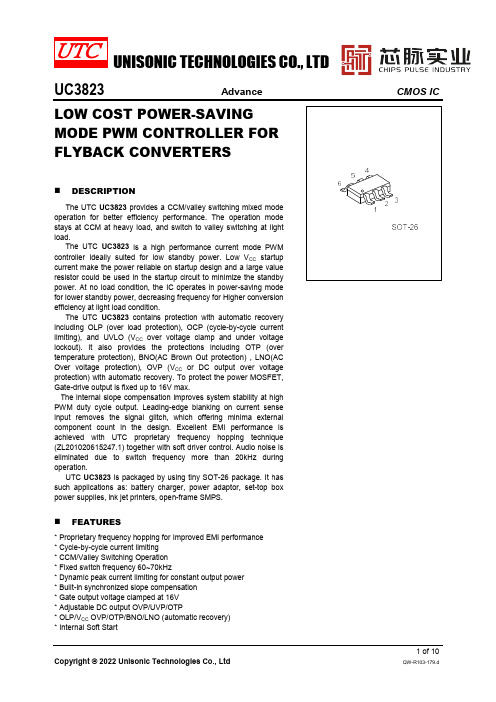
UNISONIC TECHNOLOGIES CO., LTDUC3823Advance CMOS IC LOW COST POWER-SAVINGMODE PWM CONTROLLER FORFLYBACK CONVERTERSDESCRIPTIONThe UTC UC3823provides a CCM/valley switching mixed modeoperation for better efficiency performance. The operation modestays at CCM at heavy load, and switch to valley switchin g at lightload.The UTC UC3823is a high performance current mode PWMcontroller ideally suited for low standby power. Low V CC startupcurrent make the power reliable on startup design and a large valueresistor could be used in the startup circuit to min imize the standbypower. At no load condition, the IC operates in power-saving modefor lower standby power, decreasing frequency for Higher conversionefficiency at light load condition.The UTC UC3823contains protection with automatic recoveryincluding OLP (over load protection), OCP (cycle-by-cycle currentlimiting), and UVLO (V CC over voltage clamp and under voltagelockout). It also provides the protections including OTP (overtemperature protection), BNO(AC Brown Out protection) , LNO(ACOver voltage protection), OVP (V CC or DC output over voltageprotection) with automatic recovery. To protect the power MOSFET,Gate-drive output is fixed up to 16V max.The internal slope compensation improves system stability at highPWM duty cycle output. Leading-edge blanking on current senseinput removes the signal glitch, which offering minima externalcomponent count in the design. Excellent EMI performance isachieved with UTC proprietary frequency hopping technique(ZL201020615247.1) together with soft drive r control. Audio noise iseliminated due to switch frequency more than 20kHz duringoperation.UTC UC3823 is packaged by using tiny SOT-26 package. It hassuch applications as: battery charger, power adaptor, set-top boxpower supplies, ink jet printers, open-frame SMPS.FEATURES*Proprietary frequency hopping for Improved EMI performance*Cycle-by-cycle current limiting*CCM/Valley Switching Operation*Fixed switch frequency 60~70kHz*Dynamic peak current limiting for constant output power*Built-in synchronized slope compensation*Gate output voltage clamped at 16V*Adjustable DC output OVP/UVP/OTP*OLP/V CC OVP/OTP/BNO/LNO (automatic recovery)*Internal Soft StartORDERING INFORMATIONPROTECTION MODEMARKINGPIN CONFIGURATIONPIN DESCRIPTIONBLOCK DIAGRAMABSOLUTE MAXIMUM RATINGAbsolute maximum ratings are stress ratings only and functional device operation is not implied. RECOMMENDED OPERATING CONDITIONSTHERMAL DATAELECTRICAL CHARACTERISTICS (V CC=15V, T A=25°C, unless otherwise specified)ELECTRICAL CHARACTERISTICS (Cont.)APPLICATION NOTEThe UTC UC3823 devices integrate many useful designs into one controller for low-power switch-mode power supplies. The following descriptions highlight some of the features of the UTC UC3823 series. Start-up CurrentThe start-up current is only 1μA. Low start-up current allows a start-up resistor with a high resistance and a low-wattage to supply the start-up power for the controller. For AC/DC adaptor with universal input range design, a 2.5~3MΩ, 1/8W startup resistor could be used together with a V CC capacitor to provide a fast startup and low powerdissipation solution. The D1 IN4148 can improve surge capability to 6.6KV.Fig. 1 Startup CircuitOperation ModeThe UTC UC3823 provides a CCM/valley switching mixed mode operation for better efficiency performance. The operation mode stays at CCM at heavy load, once if the converter enters into DCM, the UTC UC3823 automatically finds the local minimum V DS point and switching at this local valley. Peak load mode for heavy load condition.Normally, the conduction loss is dominated at heavy load condition, and the switching loss turns to be larger thanconduction loss in light load, especially at 1/4 ~ 1/2 of full load. By this kind of mixed mode operation to have CCM inheavy load and valley switching in light load can optimize the overall average efficiency during the entire operationrange.APPLICATION NOTE (Cont.)As shown in Fig. 3, at deep light-load or no-load condition, the switching loss is the dominant factor. To improve the light-load efficiency, burst mode operation will stop the switching cycle of the OUT pin when FB pin voltage is below “V FB_IN ” Level and restart the switching cycle of the OUT pin when FB pin voltage is above “V FB_OUT ”.Over Voltage Protection on V CC Pin ( V CC OVP )The V CC OVP will shut down the switching of the power MOSFET whenever V CC >V OVP . The OVP event as followed Fig.4.Fig.4 OVP case Fig.5 OLP caseOver Load &Open Loop & Output Short Protection ( OLP or OSP )OLP or OSP will shut down driver when V FB > V OLP for continual a blanking time. The OLP or OSP event as followed Fig.5.Over Temperature Protection ( OTP )OTP will shut down driver when the NTC resistor temperature T J >T (THR).Brown in/out and Line input OVP & DEM OVP/UVP ProtectionTo prevent high current stress at too low AC voltage condition, the UTC UC3823 implements an AC brown in/out protection through the DEM pin. The current sourcing out from the DEM pin when the OUT pin is enabled is monitored to have the AC input voltage level information. When the current keeps above the DEM_BNI threshold (I BNI ) for more than BNI De-bounce time 7 cycles, the AC brown in condition is issued and the OUT is enabled. Once if the current keeps under the DEM_BNO threshold (I BNO ) for more than BNO De-bounce time, the AC brown out condition is issued and the OUT is disabled.The equation is used to calculate the brown in/out level:AUXPRI U_DEM BNI BNI _AC N N ×2R ×I =V , AUXPRI U_DEM BNO BNO _AC N N ×2R ×I =VAPPLICATION NOTE (Cont.)To prevent line AC input voltage too high, the UTC UC3823 implements an AC input LNO protection through the DEM pin. The current sourcing out from the DEM pin when the OUT pin is enabled is monitored to have the AC input voltage level information. When the current keeps above the DEM_LNO threshold (I LNO ) for more than LNO De-bounce time 7 cycles, AC input LNO protection is enabled and the out is off. The equation is used to calculate the LNO level:AUXPRI U_DEM LNO LNO _AC N N ×2R ×I =V An over voltage protection for Vo is fulfilled by sampling the voltage on the DEM waveform after OUT is turn-off. After a short delay after OUT off, the sampled voltage is compared to the internal over voltage reference is determined whether if an OVP event is occurred. The internal over voltage reference is biased at V DEM_OVP , uses can define the resistor divider ratio by the equation below based on the desired OVP level:AUXSEC D_DEM D_DEM U _DEM OVP _DEM OVP _O N N ×R R +R ×V =V An under voltage protection for Vo is fulfilled by sampling the voltage on the DEM waveform after OUT is turn-off. After a short delay after OUT off, the sampled voltage is compared to the internal under voltage reference is determined whether if an UVP event is occurred. The internal under voltage reference is biased at V DEM_UVP , uses can define the resistor divider ratio by the equation below based on the desired UVP level:AUXSEC D_DEM D_DEM U _DEM UVP _DEM UVP _O N N ×R R +R ×V =V NFig. 6 DEM-Pin DividerAPPLICATION NOTE (Cont.)Cycle by Cycle Over-Current Protection ( OCP )In a Flyback topology converter, the main MOSFET switch of the Flyback converter turns on and off rapidly. The energy is stored in the inductor when the MOSFET turns on. The inductor current flowing through the sensing resistor (R CS ) is shown in Fig.7. The current limit is determined by the equation below:CSCS PEAK R V =I In order to prevent the CS pin from false triggering, an internal leading edge blanking time (350nS Typ.) is added and an external low pass RC filter is also recommended to filter the turn-on spike of CS node.I C S _C o m p (u A )Fig. 7 Current SensingTYPICAL APPLICATION CIRCUIT。
- 1、下载文档前请自行甄别文档内容的完整性,平台不提供额外的编辑、内容补充、找答案等附加服务。
- 2、"仅部分预览"的文档,不可在线预览部分如存在完整性等问题,可反馈申请退款(可完整预览的文档不适用该条件!)。
- 3、如文档侵犯您的权益,请联系客服反馈,我们会尽快为您处理(人工客服工作时间:9:00-18:30)。
IMPORTANT NOTICE
Texas Instruments Incorporated and its subsidiaries (TI) reserve the right to make corrections, modifications, enhancements, improvements, and other changes to its products and services at any time and to discontinue any product or service without notice. Customers should obtain the latest relevant information before placing orders and should verify that such information is current and complete. All products are sold subject to TI’s terms and conditions of sale supplied at the time of order acknowledgment.
TI warrants performance of its hardware products to the specifications applicable at the time of sale in accordance with TI’s standard warranty. Testing and other quality control techniques are used to the extent TI deems necessary to support this warranty. Except where mandated by government requirements, testing of all parameters of each product is not necessarily performed.
TI assumes no liability for applications assistance or customer product design. Customers are responsible for their products and applications using TI components. To minimize the risks associated with customer products and applications, customers should provide adequate design and operating safeguards.
TI does not warrant or represent that any license, either express or implied, is granted under any TI patent right, copyright, mask work right, or other TI intellectual property right relating to any combination, machine, or process in which TI products or services are used. Information published by TI regarding third–party products or services does not constitute a license from TI to use such products or services or a warranty or endorsement thereof. Use of such information may require a license from a third party under the patents or other intellectual property of the third party, or a license from TI under the patents or other intellectual property of TI.
Reproduction of information in TI data books or data sheets is permissible only if reproduction is without alteration and is accompanied by all associated warranties, conditions, limitations, and notices. Reproduction of this information with alteration is an unfair and deceptive business practice. TI is not responsible or liable for such altered documentation.
Resale of TI products or services with statements different from or beyond the parameters stated by TI for that product or service voids all express and any implied warranties for the associated TI product or service and is an unfair and deceptive business practice. TI is not responsible or liable for any such statements.
Mailing Address:
Texas Instruments
Post Office Box 655303
Dallas, Texas 75265
Copyright 2002, Texas Instruments Incorporated。
