模组安装说明书
GODEX EZ-1105 EZ-1305 说明书
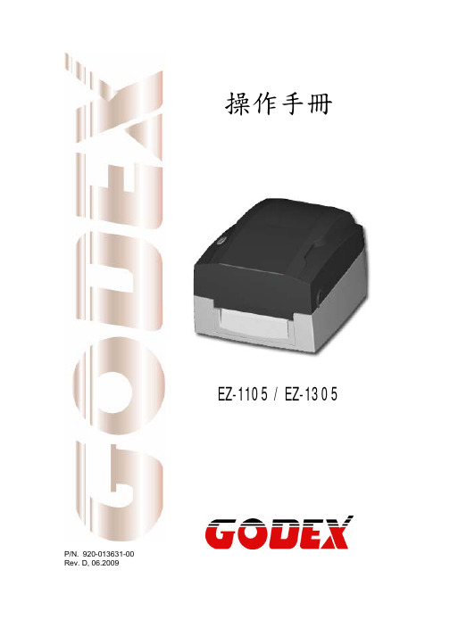
EZ-1105 / EZ-1305 User’s Manual
Only use with power supply adapter model: WDS043240 (5A).
Changes or modifications not expressly approved by the party responsible for compliance could void the user's authority to operate the equipment.
EMS AND EMI COMPLIANCE STATEMENT FOR EUROPEAN USERS
This equipment has been tested and passed with the requirements relating to electromagnetic compatibility based on the standards EN 55022:1998+A1:2000+A2:2003, CISPR 22 , Class A EN 55024:1998+A1:2001+A2:2003, IEC 61000- 4 Series EN 61000-3-2 / 2000 & EN 61000-3-3 / 1995. The equipment also tested and passed in accordance with the European Standard EN55022 for the both Radiated and Conducted emissions limits.
通元微指纹识别模组TFP625R 用户手册说明书

通元微指纹识别模组TFP625R用户手册厦门通元微智能科技有限公司目录1.产品规格 (1)2.Pin map (3)3. 概念解释 (3)1)资源开销 (3)2)模组参数 (4)3)指纹库 (4)4.通讯协议 (5)1)数据包格式 (5)2)命令码 (6)3)反馈码 (7)5. 命令 (8)GetImg (8)Img2Tz (9)Match (10)Search (10)RegModel (11)StoreModel (11)LoadChar (12)UpChar (13)DownChar (14)UpImage (15)DeleteChar (16)Empty (17)SetSysPara (17)ReadSysPara (18)SetPwd (19)VfyPwd (19)SetAddr (20)ReadINFPage (21)WriteNotePad (22)ReadNotePad (22)TemplateNum (23)ReadConList (23)Cancel (24)GetMinEmptyID (25)AutoEnroll (26)AutoIdentify (28)6.使用流程 (30)7.休眠与唤醒 (31)8.测试环境 (33)9.技术支持 (34)欢迎使用通元微指纹识别模组TFP625R 。
本文将为客户使用本模组进行指纹识别开发提供必要的说明信息。
本模组为单机指纹识别模组。
模组可以进行指纹注册、指纹识别、指纹验证等功能。
本模组支持UART通讯方式。
1.产品规格TFP625R具有模组自学习功能。
该功能会提升指纹识别的准确率。
匹配同一指纹,在匹配若干次后,匹配分数有所提升。
2.P in map连接器类型:FPC-0.5-6P: 6Pin 条形连接器,间距0.5mm。
3. 概念解释1)资源开销2)模组参数3) 指纹库图3-3, 模板与特征在Flash 中的对应成员0 成员1特征2N-1。
asustor AS6702 AS6704 AS67O6T 快速安装指南说明书

適型号AS6702/AS6704/AS6706T版本4.1.0108(2022-1-8)目录注意事项 (3)安全说明 (4)1.包装内容物 (5)2.配件选购 (7)3.硬件安装指南 (8)安装硬盘所需的工具 (8)安装硬盘 (8)固定电源线 (10)连接您的设备 (11)升级内存 (12)安装 M.2 固态硬盘 (15)安装网络适配器 (19)4. 软件安装指南 (25)使用下载中心安装 (25)使用网页安装 (27)使用行动装置安装 (28)使用LCD面板安裝 (31)5. 附录 (32)灯号指示表 (32)後面板說明 (33)LCD功能说明 (34)关闭您的设备 (36)简易故障排除 (36)注意事项联邦通信委员会声明此设备符合 FCC 规则第 15 部分。
操作受以下两个条件的约束: 本设备可能不会造成有害干扰。
本设备必须接受收到的任何干扰,包括可能导致意外操作的干扰。
本设备已经过测试,符合美国联邦通信委员会 (FCC ) 规则第 15 部分规定的 A 类数字设备限制。
这些限制旨在为住宅安装中的有害干扰提供合理的保护。
本设备产生、使用和辐射射频能量,如果不按照说明进行安装和使用,可能会对无线电通信造成有害干扰。
但是,不能保证在特定安装中不会发生干扰。
如果本设备确实对无线电或电视接收造成有害干扰(可以通过关闭和打开设备来确定),则鼓励用户尝试通过以下一种或多种措施来纠正干扰: 重新定向或重新定位接收天线。
增加设备和接收器之间的距离。
将设备连接到与接收器所连接的电路不同的电路上的插座。
请咨询经销商或有经验的无线电/电视技术人员寻求帮助。
未经负责合规的一方明确批准的更改或修改可能会使用户操作设备的权限失效。
CE Mark Warning无无线局域网/蓝牙设备的 CE 标志本设备的出厂版本符合 EEC 指令 2004/108/EC"电磁兼容性"和 IEC60950-1:2005(第 2 版)+A1:2009"信息技术设备安全"的要求。
UM220-IV M0 工规级多系统 GNSS 导航定位模组说明书
INSTALLATION AND OPERATIONUSER MANUAL UM220-IV M0工规级多系统GNSS导航定位模组修订记录免责声明本文档提供有关和芯星通科技(北京)有限公司(以下简称和芯星通)产品的信息。
本文档并未以暗示、禁止反言或其他形式转让本公司或任何第三方的专利、商标、版权或所有权或其下的任何权利或许可。
除和芯星通在其产品的销售条款和条件中声明的责任之外,本公司概不承担任何其它责任。
并且,和芯星通对其产品的销售和/或使用不作任何明示或暗示的担保,包括对产品的特定用途适用性、适销性或对任何专利权、版权或其它知识产权的侵权责任等,均不作担保。
若不按手册要求连接或操作产生的问题,本公司免责。
和芯星通可能随时对产品规格及产品描述作出修改,恕不另行通知。
对于本公司产品可能包含某些设计缺陷或错误,一经发现将收入勘误表,并因此可能导致产品与已出版的规格有所差异。
如客户索取,可提供最新的勘误表。
在订购产品之前,请您与本公司或当地经销商联系,以获取最新的规格说明。
UM220-IV M0 User Manual*和芯星通、UNICORECOMM,UFirebird及其徽标已由和芯星通科技(北京)有限公司申请注册商标。
其它名称和品牌分别为其相应所有者的财产。
版权所有 © 2009-2022,和芯星通科技(北京)有限公司。
保留所有权利前言本《用户手册》为您提供有关和芯星通UM220-IV M0模块的硬件特性,安装使用和性能指标等信息。
适用读者本《用户手册》适用于对GNSS模块有一定了解的技术人员使用。
文档结构本《用户手册》包括以下各章内容:1 产品介绍:概述产品的功能与特性2 产品安装:提供有关模块的安装指导3 技术指标:提供模块的相关技术指标4 硬件设计:简要介绍模块的引脚功能定义、布线及硬件接口参考设计等5 模块拆卸说明6 包装:提供关于UM220-IV M0模块的包装说明7 清洗8 回流焊UM220-IV M0 User Manual目录1产品介绍 (1)1.1概述 (1)1.2关键指标 (2)1.3产品概述 (3)2产品安装 (4)2.1安装准备 (4)2.2硬件安装 (5)3技术指标 (6)3.1电气特性 (6)3.2运行条件 (6)3.3外形尺寸 (7)3.4引脚功能描述(图) (8)4硬件设计 (9)4.1设计注意事项 (9)4.2避免模块串电 (10)4.3天线 (10)4.4串口 (11)5模块拆卸说明 (11)6包装 (12)6.1标签说明 (12)6.2包装说明 (12)7清洗 (13)8回流焊 (14)1 产品介绍1.1 概述和芯星通UM220-IV M0为双系统GNSS 系列模组,基于完全自主知识产权的多系统、低功耗、高性能SoC 芯片——UFirebird 设计,支持BDS B1+GPS L1双系统联合定位,或单系统独立定位。
雄迈模组 使用方法-概述说明以及解释

雄迈模组使用方法-概述说明以及解释1.引言1.1 概述概述雄迈模组是一种用于无线通信的模块,具有广泛的应用领域。
它采用先进的无线技术,能够在不同的场景中实现可靠的数据传输和通信。
该模组具有高度集成化的特点,可以方便地与各种设备进行连接和集成使用。
本篇文章将对雄迈模组进行详细介绍,并介绍了其使用方法。
首先,我们将通过对雄迈模组的基本介绍,为读者提供对该模组的整体了解。
然后,我们将详细介绍雄迈模组的使用步骤,包括配置和连接过程等。
通过本文的阅读,读者将能够全面了解雄迈模组的特点和功能,并能够掌握使用该模组的步骤和技巧。
同时,本文还将展望雄迈模组在未来的发展方向,为读者提供对该模组的使用的展望和思考。
希望本文能够对读者在使用雄迈模组时提供一定的帮助和指导。
接下来,我们将详细介绍雄迈模组的基本介绍。
文章结构部分的内容应该介绍整篇文章的组织架构和内容安排。
可以包括以下几点:1.2 文章结构本文主要分为引言、正文和结论三个部分。
下面将分别对每个部分的内容进行说明:引言部分(Chapter 1)旨在给读者提供对文章主题的概述和背景信息。
其中,1.1 概述将简要介绍雄迈模组,提供读者对该模组的基本了解。
1.2 文章结构部分则详细说明了整篇文章的组织结构。
1.3 目的部分将解释写作本文的目的和意义,即为读者提供有关雄迈模组使用方法的全面指导。
正文部分(Chapter 2)是文章的核心内容,主要包含两个部分,分别是2.1 雄迈模组的基本介绍和2.2 雄迈模组的使用步骤。
2.1 雄迈模组的基本介绍将从多个方面对该模组进行详细说明,包括技术参数、功能特点、适用范围等等。
2.2 雄迈模组的使用步骤将按照一定的逻辑顺序,从购买模组开始,逐步介绍模组的安装配置、使用方法和注意事项等,以便读者能够全面了解和正确操作雄迈模组。
结论部分(Chapter 3)将对全文进行总结,指出本文所介绍的雄迈模组使用方法的主要要点,并进行简要回顾。
安装说明书 - PowerFlex
Installation Instructions PowerFlex ® DC Drive - Frame B Switching Power Supply Circuit Board What This Kit Includes•Switching Power Supply circuit board •16 Pin Ribbon cable •Four screws with captive lock washers •Four metal stand-offs •Two plastic screws •Two plastic stand-offs •SA-SB terminal block •Static strap Tools That You Need •Phillips ® screwdriver•Flathead screwdriver•Nut driver or wrench for hex stand-offsPhillips ®is a registered trademark of Phillips Screw Company.ATTENTION: Only qualified personnel familiar with DC drives and associated machinery should plan or implement the installation, start-up and subsequent maintenance of the system. Failure to comply may result in personal injury and/or equipmentdamage.ATTENTION: To avoid an electric shock hazard, ensure that all power to the drive has been removed before performing thefollowing.ATTENTION: This drive contains ESD (Electrostatic Discharge) sensitive parts and assemblies. Static control precautions are required when installing, testing, servicing or repairing this assembly. Component damage may result if ESD control procedures are not followed. If you are not familiar with static control procedures, reference A-B publication 8000-4.5.2, “Guarding Against Electrostatic Damage” or any other applicable ESD protection handbook.2PowerFlex® DC Drive - Frame B Switching Power Supply Circuit BoardWhat You Need to DoTo install the Switching Power Supply board:❐ Step 1:Remove power from the drive ❐ Step 2:Remove the protective covers ❐ Step 3:Remove the existing Switching Power Supply board ❐ Step 4:Install the new Switching Power Supply board ❐ Step 5:Replace the protective covers and document the change Step 1:Remove Powerfrom the Drive1.Remove and lock-out all incoming power to the drive. ATTENTION: Remove power before making or breaking cable connections. When you remove or insert a cable connector with power applied, an electrical arc may occur. An electrical arc can cause personal injury or property damage by:•sending an erroneous signal to your system’s field devices, causing unintended machine motion •causing an explosion in a hazardous environment Electrical arcing causes excessive wear to contacts on both the module and its mating connector. Worn contacts may create electrical resistance.PowerFlex® DC Drive - Frame B Switching Power Supply Circuit Board3Step 2:Remove the Protective Covers 1.Disconnect the DPI cable from the HIM assembly (if present).2.Loosen, but do not remove, the screws that secure the bottom cover tothe drive, then slide the cover down and off the drive chassis.3.Loosen, but do not remove, the screws that secure the top cover to thedrive, then slide the cover up and off the drive chassis.Important:The HIM assembly is connected via a cable to the Control board and therefore will not pull free from the drive untildisconnected. See step 4 below for instructions.4PowerFlex® DC Drive - Frame B Switching Power Supply Circuit Board4.Disconnect the HIM Communication cable from the connector on theupper right corner of the Control board and set the cover aside.Pull tabs out to disconnect cable.PowerFlex® DC Drive - Frame B Switching Power Supply Circuit Board5Step 3:Remove the Existing Switching Power Supply Board Note: The Switching Power Supply circuit board is located on the back of the Pulse Transformer circuit board. You must move the Control EMI shield and remove the top air flow plate from the drive in order to remove the board.1.Carefully disconnect the cables from connectors XA, XR and XFCD onthe Control board.2.Loosen the two captive screws at the top of the Control EMI shield andlower the shield.Important:If the drive is not in a vertical position, the Control EMIshield will not remain open without a means of restraint.Loosen screws6PowerFlex® DC Drive - Frame B Switching Power Supply Circuit Board3.Remove the plug-in terminal from the field input block at the top of thedrive.4.Remove the four screws that secure the slotted air flow plate to the topof the drive chassis.Important:The air flow plate is also secured to the Pulse Transformercircuit board and therefore cannot yet be removed.Instructions for doing so are included later in thisprocedure.5.Remove the two screws that secure the air flow plate to the top of thePulse Transformer board and lift the plate off the drive chassis. The airflow plate cannot be completely removed due to the fuse connections at FU1 and FV1. Air flow plateplug-interminalFront of Drive Remove screwsFuse connections Pulse Transformer boardPowerFlex® DC Drive - Frame B Switching Power Supply Circuit Board 76.Remove the cable from connector XP in upper right corner of the PulseTransformer board.Important:Provide support for the Switching Power Supply board asyou remove the screws from the Pulse Transformer board.7.Remove the six screws that secure the stand-offs on the back of theSwitching Power Supply board to the Pulse Transformer board.Disconnect cableRemove screwsRemove screws8PowerFlex® DC Drive - Frame B Switching Power Supply Circuit Board8.Remove the cables from connectors XV and XUV on the SwitchingPower Supply board and slide the board out of the drive chassis.9.Remove the six screws that secure the stand-offs to the back of theSwitching power Supply board and remove the stand-offs. Retain thestand-offs for reuse.Remove cable from XUV Remove cable from XVRemove screwsPowerFlex® DC Drive - Frame B Switching Power Supply Circuit Board 9Step 4:Install the NewSwitching Power SupplyBoard 1.Install the new Switching Power Supply board in reverse order of removal as detailed in Step 3: Remove the Existing Switching Power Supply Board on page 5.2.Replace the 16 Pin cable connected to connector XA on the SwitchingPower Supply board with the new cable provided.–Verify that the four plastic board stabilizers mounted on the top airflow plate are placed one on either side of each of the Pulse Transformer and Switching Power Supply boards.Top view of Pulse Transformer board Side cut-away viewPublication 20P-IN006B-EN-P - December 2009Supersedes 20P-IN006A-EN-P - March 2009Copyright © 2009 Rockwell Automation. All rights reserved. Printed in USA.Step 5:Replace theProtective Covers andDocumenting the Change 1.Replace the protective covers in the reverse order of removal as described in Step 3: Remove the Protective Covers on page 3.2.Install DPI cable (if present).3.Record the installation of the new Switching Power Supply board anddate of installation on the Field Installed Option label on the side of thedrive (as shown below).Related Documentation Allen-Bradley publications are available on the internet at/literature .For . . .Read this document Publication Number In depth information regarding theoperation of PowerFlex Digital DC drives User Manual - PowerFlex Digital DC Drives 20P-UM001…。
华为 MH5000-31 5G 模组使用手册说明书

华为MH5000-31 5G模组使用手册目录华为MH5000-31 5G模组使用手册 (1)模组介绍 (2)Windows平台使用指南 (3)Ubuntu/CentOS使用指南 (8)树莓派4B使用指南 (13)Raspberry Pi OS (13)树莓派4B+OpenWrt (15)SA网络使用 (21)模组介绍⚫Usb接口为TypeC的USB 3.0接口,请使用TypeC接口的数据线,建议使用USB 3.0数据线,USB 2.0也同样兼容,但速率会收到USB 2.0的影响,USB 2.0最高下行速率为480Mbps,实际使用中真实速率根据当地的实际网络情况决定。
USB插入时请水平插入,不要向上用力掰。
⚫电源接头为12V/5V接头,模组会配套带一根电源线,默认使用12V电源。
红色的线为12V电源,黄色为5V(默认未接),请使用12V/1A以上电源。
如果需要使用5V电源,请保证5V/1.6A以上的供电。
通常情况下,USB也可以直接给模块供电,但有些主机的USB接口供电能力不足,会影响模块使用,建议连接12V电源。
⚫天线一共4根,接头为IPEX1,主天线必须接,否则可能无法正常注册网络和拨号,其它三根天线为分集天线和MIMO天线,普通测试可不接,如果需要进行网络测速,建议四根天线全部连接上。
⚫SIM卡槽在模组板背面,为Micro SIM卡,支持热插拔。
Windows平台使用指南1.硬件连接插入SIM卡,数据线连接到模组TypeC USB接口和主机的USB 3.0接口,连接模块电源。
2.安装5G模块驱动MH5000-31_Windows_debug_driver(20200331)双击驱动安装程序,确认后,驱动自动安装,没有安装界面,安装完成后,请重启电脑。
电脑重启后,插上5G模组,查看我的电脑->设备管理器,驱动安装成功后,会出现四个串口设备,其中PC UI Interface为模组的AT控制串口。
LDK模组安装手册
• 雪压:
低于 112,78 lb / ft2 (5400Pa)
• 耐腐蚀性: 除含盐和含硫磺腐蚀性区域。
组件安装在屋顶或建筑物上时,要确保它被安全地固定并且不会因为
强风或大雪而破坏,并且背面要确保通风顺畅以便组件的冷却 ( 组件和安
装表面的最小间隔为 10cm )。
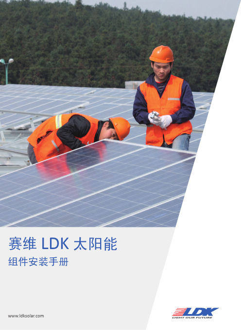
标准安装时,使用边框上内侧的四个对称的安装孔 (14mm x 9mm),用 M8 防腐蚀螺丝与弹性垫圈和平垫圈,用一个约 8N*m 的扭力将组件固定在支撑结构上。在有强风或大雪的地区,同时使 用外侧对称的安装孔来加强固定,参见上图。
ULC/ORD-C1703-01 UL 及加拿大标准用于平板型太阳能组件安全认证标准 ISO 9001 用于制造及销售太阳能光伏组件质量管理体系
担保期 LDK 对组件担保条件规定在名为 LDK 太阳能标准光伏组件保修文件中
假如忽略在此规定的说明和注意事项而造成疏忽,将导致 LDK 解除保单。 请联系我们的技术支持部门询问任何有关担保方面的事情。
组件可提供预制连接器,用于系统的电气连接。这些电缆导线和连接 器不得拆除或切断。电缆线尺寸、类型和温度等参数的选择请参考相关的 规程。
系统接地
• 所有的组件框架和安装支架都必须合理地接地。使用推荐的连接端子并 将接地电缆良好地连接,固定到组件框架上。 • 使用经过电镀处理的支撑框架,以保证电路导通良好。 • 用一适当的接地导体,将该组件框架和支撑构件连接,可做到合适的接 地效果。 • 接地导体必须通过一个适当的地面电极连接到地面。推荐使用接地线配 件(接线鼻)连接接地电缆。若没有通过螺栓和螺母连接机械地到已接地 的光伏组件上,支架也必须接地。
注:不允许拆卸,钻孔或改装光伏组件。倘若这样做会导致保修无效。如 果对组件的安装程序不明确,请联系 LDK 技术服务。
丝杆模组光电EE-SX672位置安装调整

三、托盘移动X轴介绍Biblioteka 丝杆模组光电EE-SX672位置调整
第3页
X轴正面
1、1套模组需3个光电开关做信号反馈检测;左右位置极限各1个,中间原点1个; 通常原点安装在电机一侧;
四、工作位置调整:
丝杆模组光电EE-SX672位置调整
第4页
左移极限位
右移极限位
左移工作位
右移工作位
1、在伺服不通电的状态下,手动将托盘向左右移动至极限位,比较极限位和工 作位,丝杆左右余下间距;以放料杆做相对位置参考; 2、上图可以看出左右极限位置超出了工作位孔一半,有足够间距; 3、手动移动托盘参照放料杆,将托盘左右移动在工作位置,放料杆对托盘孔中 心,调整好左右工作位后,将光电左右极限位置调整好,光电靠近遮光片灭为原 点向外移动2mm,为光电安装调整位置; 4、原点光电靠近电机一侧安装在极限光电内侧;
一、机构外形:
丝杆模组光电EE-SX672位置调整
第1页
放料搬 送Y轴
托盘移 动X轴
1、放料搬送Y轴将转盘产品搬送致托盘,排满一排后;托盘移 动X轴移动一个间距,Y轴继续放料到托盘放满;
二、EE-SX672介绍:
丝杆模组光电EE-SX672位置调整
第2页
遮光片未遮住亮
遮光片遮住灭
1、672采用标准的U字型结构,其发射器和接收器分别位于U型槽的两边, 并形成一光轴,当被检测物体经过U型槽且阻断光轴时,光电开关就产生 了开关量信号反馈给PLC做程序控制。 2、感应片在未遮住光电开关光束亮,遮住光电光束灭,如上图亮和灭的 间距0.5mm;
上海庆科信息技术有限公司EMW3090 Wi-Fi模组产品手册说明书
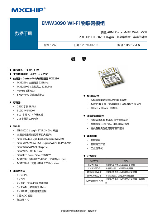
概 要l 电压输入: 3.0V~3.6V l 工作环境温度:-20℃ to +85℃l 处理器:Cortex-M4内核处理器MX1290§ MX1290:主频高达125MHz § MX1290v2:主频高达62.5MHz § 40MHz 时钟输入 § SWD/JTAG 仿真调试接口 l 存储器§ 256K 字节SRAM § 512K 字节ROM § 512 字节 OTP 存储区域 § 2M 字节的XIP 闪存 l Wi-Fi§ IEEE 802.11 b/g/n 1T1R 2.4GHz 单频 § 内置自校准功能的功率放大器(PA)§ 支持 802.11e QoS Enchantement (WMM) § 支持 WPA/WPA2 PSK,Open/WEP/ TKIP/CCMP § 支持 WPA/WPA2 Enterprise § 支持WPS,Wi-Fi Direct § 支持IEEE Power Save 节能模式§ MX1290:支持HT20/HT40,150Mbps max. § MX1290v2:支持HT20, 72Mbps max. l 丰富的外设§ 11 x GPIO § 1 x SPI§ 2 x I2C,支持400K 高速模式 § 5 x PWM,频率高达2MHz § 2 x UART,支持硬件流控制 § 1路ADC 通道 § 低功耗RTCl 接口和尺寸§ 保持与同类封装模组的引脚兼容性§ 板载PCB 天线,或者用IPEX 连接器接外接天线 § 18mm x 20mm,邮票孔 l 丰富的配套软件§ 支持AliOS 和MXOS 自主操作系统 § 提供各大云平台接入SDK 和AT 指令 § 提供各种典型应用的可量产固件 l 典型应用§ 智能家电 § 智能电工产品 § 工业自动化l 订货代号订货代号 说明EMW3090-P 板载PCB 天线,MX1290处理器 EMW3090-E 外接天线座, MX1290处理器 EMW3090V2-P 板载PCB 天线,MX1290v2处理器 EMW3090V2-E 外接天线座,MX1290v2处理器EMW3090V2-P-TR板载PCB 天线,MX1290v2处理器,卷带包装EMW3090 Wi-Fi 物联网模组内置ARM Cortex-M4F Wi-Fi MCU2.4G Hz IEEE 802.11 b/g/n、超高集成度、丰富的外设 版本:2.6日期:2020-10-19编号:DS0125CN!"#$%&例如 EMW 3 09 0 V2 -P -xxx 产品系列EMW=物联网Wi-Fi模组产品类型3=焊接类无线模组典型目标应用和功能09=IOT物联网应用9系列外形尺寸,增强功能0=18mm x 20mm,2 x 9 pins 1.5间距邮票孔射频接口[省略]=使用MX1290主控芯片V2=使用MX1290V2主控芯片Flash容量P=2.4GHz板载PCB天线E=2.4GHz外置天线IPEX接头可选项TR = 卷带包装(!"#$%&'如需了解所有相关特性清单(如包装,最小订单量等)和其他方面的信息,请联系就近MXCHIP销售点和代理商。
LED显示屏 模组安装作业指导书

3NO 模组
箱体静电环电批/风批胶锤1/1审 批作业指导书
后工序生产工 作 名 称
模组安装制 作 日 期2007/7/6
版本注意事项
文件编号 NO 使 用 物 料
作业顺序及内容
页 数1、拿起模组先检查防水胶圈,再确认向上标识是否与铁箱方向一致.
2、一人在箱体正面扶着模组,一人在后面打螺丝
3、当模组间缝隙过大而手工无法调整时,可用胶锤轻轻敲击模组边缘1、作业过程中应做好静电防护
2、模组是否装有防水胶圈,胶圈是否装好
3、模组向上方向要和铁箱向上方向相符
4、注意模组表面平整度,模组间左右,上下缝隙应﹤1mm。
5、电批/气批的扭力要合标准
6、螺丝要打紧到位,不要出现打花现象使 用 工 具批 准 作 成组合机牙螺丝
12312防水胶圈向上标识。
炜盛 甲醛模组 ZE08-CH2O 使用说明书

甲醛模组(型号:ZE08-CH2O)使用说明书版本号:1.7实施日期:2020.04.17郑州炜盛电子科技有限公司Zhengzhou Winsen Electronic Technology Co.,Ltd声明本说明书版权属郑州炜盛电子科技有限公司(以下称本公司)所有,未经书面许可,本说明书任何部分不得复制、翻译、存储于数据库或检索系统内,也不可以电子、翻拍、录音等任何手段进行传播。
感谢您使用炜盛科技的系列产品。
为使您更好地使用本公司产品,减少因使用不当造成的产品故障,使用前请务必仔细阅读本说明书并按照所建议的使用方法进行使用。
如果您不依照本说明书使用或擅自去除、拆解、更换传感器内部组件,本公司不承担由此造成的任何损失。
您所购买产品的颜色、款式及尺寸以实物为准。
本公司秉承科技进步的理念,不断致力于产品改进和技术创新。
因此,本公司保留任何产品改进而不预先通知的权力。
使用本说明书时,请确认其属于有效版本。
同时,本公司鼓励使用者根据其使用情况,探讨本产品更优化的使用方法。
请妥善保管本说明书,以便在您日后需要时能及时查阅并获得帮助。
郑州炜盛电子科技有限公司产品描述电化学甲醛模组ZE08-CH 2OZE 08-CH 2O型电化学甲醛模组是一个通用型、小型化模组。
利用电化学原理对空气中存在的CH 2O进行探测,具有良好的选择性,稳定性。
内置温度传感器,可进行温度补偿;同时具有数字输出与模拟电压输出,方便使用。
ZE 08-CH 2O是将成熟的电化学检测技术与精良的电路设计紧密结合,设计制造出的通用型气体模组。
模组特点高灵敏度、高分辨率、低功耗、使用寿命长提供UART 、模拟电压信号等多种输出方式高稳定性、优秀的抗干扰能力、温度补偿、卓越的线性输出主要应用便携式仪表、空气质量监测设备、空气净化机、新风换气系统、空调、智能家居设备等场所。
技术指标表1图1:模组结构图产品型号ZE 08-CH 2O 检测气体甲醛干扰气体酒精,一氧化碳等气体输出数据DAC(0.4~2V 电压信号对应浓度:0~满量程)UART 输出(3V TTL 电平)工作电压 3.7V~5.5V 预热时间≤3分钟响应时间≤60秒恢复时间≤60秒量程0~5ppm 分辨率≤0.01ppm 工作温度-20℃~50℃工作湿度15%RH-90%RH(无凝结)存储温度0~25℃使用寿命5年(空气中18℃~25℃)管脚定义表2管脚名称管脚说明Pin1预留Pin2DAC(0.4~2V,对应0-满量程)Pin3GNDPin4Vin(电压输入 3.7V~5.5V)Pin5UART(RXD)0~3.3V 数据输入Pin6UART(TXD)0~3.3V 数据输出Pin7预留图2:模组引脚图通讯协议1通用设置表3波特率9600数据位8位停止位1位校验位无2通讯命令通信分为主动上传式和问答式,出厂默认主动上传,每间隔1S发送一次浓度值。
HLK-LD2410B人体存在感应模组说明书

深圳市海凌科电子有限公司HLK-LD2410B人体存在感应模组说明书目录1产品简介 (3)2产品特点和优势 (4)2.1特点 (4)2.2方案优势 (5)3应用场景 (6)4硬件说明 (7)4.1外形尺寸 (7)4.2引脚定义 (7)5使用和配置 (8)5.1典型应用电路 (8)5.2配置参数的作用 (8)5.3可视化配置工具说明 (9)5.4安装方式和感应范围 (10)5.5安装条件 (12)6蓝牙使用说明 (13)6.1安装软件 (13)6.2使用方法 (13)6.3蓝牙密码 (14)6.4OTA升级 (14)6.5蓝牙通讯协议 (16)6.6再次打开蓝牙 (17)7性能和电气参数 (17)8天线罩设计指南 (18)8.1天线罩对毫米波传感器性能的影响 (18)8.2天线罩的设计原则 (18)8.3常见材料 (18)9修订记录 (20)10技术支持和联络方式 (21)1产品简介LD2410B是海凌科电子开发的一款高灵敏度的24GHz人体存在状态感应模组。
其工作原理是利用FMCW调频连续波,对设定空间内的人体目标进行探测,结合雷达信号处理、精确人体感应算法,实现高灵敏度的人体存在状态感应,可识别运动和静止状态下的人体,并可计算出目标的距离等辅助信息。
本产品主要应用在室内场景,感知区域内是否有运动或者微动的人体,实时输出检测结果。
最远感应距离可达6米,距离分辨率0.75m。
提供可视化的配置工具,可轻松配置感应距离范围、不同区间的感应灵敏度和无人延时时间等,适应不同的具体应用需求。
支持GPIO 和UART输出,即插即用,可灵活应用于不同的智能场景和终端产品。
高度1.5~2米图1使用方式图示2产品特点和优势2.1特点●即插即用,简易装配方式●最远感应距离为可达6米●探测角度大,覆盖范围可达±60度●区间内准确识别,支持感应范围划分,屏蔽区间外干扰●可以通过蓝牙或串口实现多级智能调参,满足场景变化需求●可视化调试和配置工具●小巧简化,最小尺寸仅为7mmx35mm●支持挂顶、挂壁等多种安装方式●24GHz ISM频段,可通过FCC和CE频谱法规认证●极致性价比之选2.2方案优势LD2410B人体感应模组采用24GHz毫米波雷达传感器技术,和其他方案对比,在人体感应应用上有着明显的优势:1.除了对运动人体感应灵敏外,对于传统方案无法识别的静止、微动、坐卧人体也都可灵敏感应到;2.有良好的环境适应性,感应效果不受温度、亮度、湿度和光线波动等周围环境影响;3.有良好的外壳穿透性,可隐藏在外壳里面工作,无需在产品表面开孔,提高了产品美观度;4.可灵活配置最远感应距离和每个距离门上的灵敏度,实现灵活精细的个性化配置;5.带有蓝牙功能,可以无需接住串口,直接使用APP调试雷达参数好一般弱图2毫米波雷达方案和其他方案对比3应用场景LD2410B人体感应模组对运动、微动和站立、坐卧的人体均可进行探测识别,支持多级调参,可广泛应用于AIoT 各种场景,常用类型如下●人体感应灯控感知所在空间是否有人存在,自动控制灯光,如公共场所照明设备、各类感应灯、球泡灯等。
蓝景光电ZA18 3.0 3030白色卡盖侧发光防水模组 说明书

产品说明书ZA18 3.03030白色卡盖侧发光防水模组产品特点:安装方式:◇光源采用3030封装的LED灯珠;用3M胶粘贴固定 ,或螺丝固定。
8cm厚度以上的双面灯箱,8-10cm的导向标识牌等等.用 途:备注:①.测试环境温度为 25±2℃;②.以上数据为典型值,产品的实际参数可能会不同于典型数据,数据如有更改,恕不另行通知;③.以上光通量按照单色点亮时,测试的参数;④.如果选用不同档位的灯珠,色温会不同,光通量有一定的浮动。
最小可剪数量6+N,指的是产品最少数量为6pcs一起使用,6pcs之后可以任意剪切 。
备注:如需要详细尺寸,请联系销售人员索要 。
◇◇自主设计的透镜;产品采用灌胶+超声波工艺;◇◇高功率因数PF>0.95 , 高转化效率09;>.产品可直接接市电220V使用;单位:mm[inch]产品尺寸:*AC220V14.[.55]0.1m 0.2m 0.3m 0.0.5m 0.6m 0.7m 0.8m 0.9m 1m 平均光束角度(50%):23.8度光强:cd C0/180,16C90/270,31备注:以上的两图,,在色温7836-9000K 条件下测试所得;如需其它数据,如需剪切,请在可剪标识处剪切;剪切处不能开路,必须短接.图示箭头,表示电流的流向规定的电流方向,是从电源流向产品,如上图所示.; 请联系销售人员索要。
配光曲线:可剪性示意图:有效平均照度:包装示意:将产品整齐放入外箱将捆好扎带的产品装进防静电屏蔽袋中 并 放入干燥剂防静电袋封好口外贴标签装入外纸箱将外箱打上封口胶,并在干燥剂12345准备好干燥剂,将产品捆好扎带外箱上贴好标签6301. 本产品采用防静电屏蔽袋密封装载,使用普通外箱包装;2. 上述包装数量和重量只针对图示包装方式,当为其它包装方式时 , 包装数量和重量会存在差异,实际重量以实物为准;ZA18 3.0内贸产品尺寸(mm )总数(pcs )净重(kg )毛重(kg )型号贸易类型47*32*1480021.82(1±10%)23.35(1±10%)包装说明:纸箱尺寸(mm )570*375*285安装部分:二、产品部分和所需工具示意图一、安装数据产品型号灯箱类型打光方式透光材料对打距离m灯箱深度cm安装密度PCS/2m表面照度lux均匀度ZA183.0双面灯箱白色软膜双侧对打1.08101266816*21270-16200.7816*21180-15300.7712*21030-13600.761.58101266816*2810-14400.5616*2770-13500.5712*2710-12600.56间距 (X)cm备注:安装密度,是按照1平米的灯箱安装 .PCS/m表示单边安装的数量 ,PCS/2m表示双边安装的数量.①"表示2条安装边每边装16PCS产品;,指的是,在安装边上产品的用量;在拉布灯箱内安装本光电产品后,须在48小时内进行蒙布处理;严禁安装产品后的灯箱不蒙布地使用或者长期闲置。
ZE08-CH2O甲醛模组说明书1.0

表5 浓度 50ppm 100ppm 10ppm 5ppm 100ppm 10ppm
输出浓度 0ppm
0.1ppm 0.1ppm 0.1ppm 0.2ppm 0.5ppm
创造完美、服务社会
二氧化硫 硫化氢 氢气 乙醇 甲醇 甲醛
20ppm 100ppm 500ppm 131ppm 42ppm 5ppm
图 2: 模组引脚图
通讯协议
1 通用设置
波特率 数据位 停止位 校验位
表3
9600 8位 1位 无
2 通讯命令
通信分为主动上传式和问答式,出厂默认主动上传,每间隔1S发送一次浓度值,命令行格式如下
表4
0
1
起始位 气体名称
2 单位
3
4
5
6
7
8
小数位数 气体浓度 气体浓度 满量程 满量程 校验值
CH2O
以诚为本、信守承诺
创造完美、服务社会
以诚为本、信守承诺
图 1: 模组结构图
创造完美、服务社会
电化学模组系列
管脚定义
管脚名称 Pin4 Pin3 Pin2 Pin7 Pin1 Pin5 Pin6
表2
管脚说明 Vin(电压输入 3.7V~9V)
GND DAC (0.4~2V,对应 0-满量程)
PWM HD (校零,暂不开放) UART(RXD) 0~3.3V 数据输入 UART(TXD) 0~3.3V 数据输出
模组特点 高灵敏度、高分辨率、低功耗、使用寿命长 提供 UART、模拟电压信号、PWM 波形等多种输出方式 高稳定性、优秀的抗干扰能力、温度补偿、卓越的线性输出
主要应用 便携式仪表、空气质量监测设备、空气净化机、新风换气系统、空调、智能家居设备等场所。
FSL40直线模组使用说明书

注意:侧面安装槽可用来固定接近开关,不可用来固定模组。
FS L 40直线模组是本司推出的一款高性价比丝杆直线模组,本体宽度40mm,最大有效行程可达1000mm。
采用开放式的结构(无防水防尘功能),配置单导轨,单滑块,结构紧凑,通用性强,适用于中低负载中等速度的要求,可单轴或多轴组合使用,方便搭配各个行业所需的工件,做到工业设备所需的简单实用的功能。
40丝杆直线模组用户使用简易说明书模组外观尺寸:模组安装尺寸:技术参数:模组使用环境及注意事项参数测试条件为标准配置:电机 FM 5756SFD04 驱动器 FMDD50D40NOM 驱动电压 24VDC 电流 2A40丝杆模组常见组合台搭建展示FS L40XY-X FS L40XY-SFS L40XY-T FS L40XY-H1FS L40XY-H2FS L40XYZ-XFS L40XYZ-T FS L40XYZ-L 以上为40丝杆模组常见的8种组合台的搭建展示,具体的安装步骤请移至本司官网-技术支持栏目-产品使用手册里面下载安装步骤图纸本司官网网址:/丝杆模组通用控制方法实施一、模组的控制流程/控制原理(步进电机的控制)二、模组的控制框架/接线方法A、控制基本框架B、通用控制接线(按照基本的控制思路)控制器驱动器步进电机与电源端连线(都需要外部电源供电,应根据不同需求选择合适的电源)接电机相线(电机由驱动器供电)接控制线(PU 为脉冲端,DR 为方向端,且根据自己的控制器采取共阴极或者共阳极的接线方式)上位机(常用PC ):程序编译/指令下达控制器:信号处理/发出脉冲功能:发送一串信号,其代表有具体的意义(例如:速度,距离,停留时间等,常支持Modbus 等协议)功能:接收信号,并通过内部存储的逻辑运算或微程序,将信号转换得出脉冲频率、数量等信息,并将脉冲输出给执行部件(步进电机驱动器等其它)驱动器:接收脉冲/驱使步进电机功能:接收脉冲信号,将脉冲信号转化为驱使步进电机精确转动的相电流。
赛拉弗光伏模组安装手册说明书
Installation GuideforSERAPHIM photovoltaicmoduleTable of Contents1.Purpose of this guide ………………………………..….......No.11.1General safety …………………………………………………………………………………………..…No.11.2Handling safety ………………………………………………………..............No.11.3Installation safety ………………………………………...…………………….No.21.4Fire safety ……………………………………………………..………………..No.52.Product Identification …………………………… ………...…….…….No.53.Mechanical Installation ………………………………………...............No.63.1Selecting the location ……………………………………………………………..No.63. 2General installation ……………………………………………………………….No.63. 3 Installation method …………………………………………………………..…...No.73.4 Attachment guidelines ………………………………………………………………….…No.84. Electrical Installation …………………………………………………….No.84. 1General installation ……………………………………………………………….No.84.2 Grounding …………………………………………...…………………… ...…..No.95.Maintenance ………………………………………………………….…No.106. Dimensions & Parameters ……………………………………………..No.117. Diode Information ………………………………………………..….…No.24Purpose of this guide■This is guide contains information regarding the installation and safe handling of SERAPHIM solar system Co.,Ltd, photovoltaic module (hereafter referred to as “module”). SERAPHIM solar system Co.,Ltd. referred to as “SERAPHIM ”.■Installers must read and understand this guide prior to installation. For any questions, please contact our Global Quality & Customer Support department for further information. Installers should follow all safety precautions described in this guide as well as local codes when installing a module. ■ Before installing a solar photovoltaic system, installers should familiarize themselves with its mechanical and electrical requirements. Keep this guide in a safe place for future reference (care and maintenance) and in case of sale or disposal of the modules.General safety ■ Modules that fall under this application class may be used in system operating at more than 50V DC or 240W, where general contact access is anticipated. The module is considered to be in compliance with IEC61215&61730 only when the modules mounted in the manner specified by the mounting instructions below.■ A module with exposed conductive parts is considered to be in compliance with IEC61215&61730 only when it is electrically grounded in accordance with the instructions presented below and the requirements of the National Electrical Code.■ Installing solar photovoltaic systems requires specialized skills and knowledge. Installation should only be performed by qualified persons. ■ Installers should assume all risks of injury that might occur during installation, including, but not limited to, the risk of electric shock. ■ One single module may generate more than 30V DC when exposed to direct sunlight. Contact with a DC voltage of 30V or more is potentially hazardous. ■ Do not disconnect under load.■ Photovoltaic solar modules convert light energy to direct current electrical energy. They are designedfor outdoor use. Modules can be ground mounted, mounted on rooftops, vehicles or boats. The proper design of support structures lies within responsibility of the system designers and installers. ■ Do not use mirrors or other magnifiers to concentrate sunlight onto the modules. ■ When installing the system, abide to all local, regional and national statutory regulations. Obtain a building permit if necessary.■This product must be installed by a licensed electrician in accordance with the applicable electrical code (i.e. the NEC for the USA and CEC for Canada).■ The electrical characteristics are under standard test conditions (irradiance of 100 mW/cm2, AM 1.5 spectrum, and a cell temperature of 25°C (77°F)).■ Only use equipment, connectors, wiring and support frames suitable for solar electric systems. Handling safety ■ Do not lift the module by grasping the module’s junction box or electrical leads. ■ Do not stand or step on the module. ■ Do not drop the module or allow objects to fall on the module. ■ To avoid glass breakage, do not place any heavy objects on the module. ■ Be cautious when setting the module down on to a surface. ■ Inappropriate transport and installation may break the module. ■ Do not attempt to disassemble the modules, and do not remove any attached nameplates or components from the modules. ■ Do not apply paint or adhesive to the module top surface. ■ To avoid damage to the backsheet, do not scratch or hit the backsheet. ■ Do not drill holes in the frame. This may compromise the frame strength and cause corrosion of the frame.■ Do not scratch the anodized coating of the frame (except for grounding connection). It may cause corrosion of the frame or compromise the frame strength. ■ Be careful when setting the panel down onto a surface, particularly when placing it on a corner. ■ A panel with broken glass or torn backsheet cannot be repaired and must not be used since contact with any panel surface or the frame can cause a electric shock. ■ Work only under dry conditions, and use only dry tools. Do not handle panels when they are wet unless wearing appropriate protective equipment. ■ When storing uninstalled panels outdoors for any period of time, always cover the panels and ensurethat the glass faces down to stop water from collecting inside the panel and causing damage to exposed connectors.Installation safety ■ Any module without a frame (laminate) shall not be considered to comply with the requirements of IEC61215&61730 unless the module is mounted with hardware that has been tested and evaluated with the module under this standard or by a field Inspectioncertifying that the installed module complies with the requirements of IEC61215&61730.■ Never open electrical connections or unplug connectors while the circuit is under load. And do not disconnect during load connection for a removable connector. ■ Contact with electrically charged parts of the panels, such as terminals, can result in burns, sparks and lethal shock whether or not the panel is connected.■ Do not touch the PV module unnecessarily during installation. The glass surface and the frame may be hot; there is a risk of burns and electric shock. ■ Do not work in the rain, snow or in windy conditions. ■ Avoid exposing cables to direct sunlight in order to prevent their degradation. ■ Keep children well away from the system while transporting and installing mechanical and electrical components. ■ Do not expose the artifically sunlight to a module or panel. And completely cover the module with an opaque material during installation to prevent electricity from being generated. ■ Do not wear metallic rings, watchbands, ear, nose, lip rings or other metallic objects while installing or troubleshooting photovoltaic systems. ■ Use only insulated tools that are approved for working on electrical installations. ■ Follow the safety regulations for all other system components, including wires and cables, connectors, charging regulators, inverters, storage batteries, rechargeable batteries, etc. ■ Under normal outdoor conditions the current and voltage generated by the system will differ from those listed on the datasheet. Datasheet values are the values measured under standard test conditions.Accordingly, during system designing phase, current and short-circuit current should be multiplied by a factor of 1.25 to determine components ratings. ■ Only use connectors to connect modules to form a string, or connect to another device. Removing theconnectors will make the warranty void.Fire Safety ■ The fire rating of this module is valid only when mounted in the manner specified in the mechanical mounting instructions.■ The fire rating of the module can be referred to UL790.■ Consult your local authority for guidelines and requirements for building or structural fire safety.■ Roof constructions and installations may affect the fire safety of a building; Improper installation maycreate hazards in the event of a fire.■ Use components such as ground fault circuit breakers and fuses as required by local authority. ■ Do not use panels near equipment or in places where flammable gases may be generated.■ Do not use non-integral module and panel are installed on a roof that has fire danger. If a non-integralmodule and panel are installed on a roof that must has fire-resistant degree of class A.■ The safe distance between the module and the roof we suggest is 20~30 centimeters.Product IdentificationEach module has two labels providing the following information:1. Nameplate: describes the product type; rated power, rated current, rated voltage, open circuit voltage, short circuit current, all as measured under standard test conditions; weight, dimensions etc.; the maximum system voltage of 1500 volts DC.2. Barcode: each individual module has a unique serial number. The serial number has 17 digits. The first is type, the second is poly or mono silicon, the third is factory, the fouth and fifth is pcs of cells, the sixth to ninth is year and month, the tenth to twelfth is batch number, the thirteenth to seventeenth is number . Each module has only one barcode. It is permanently attached to the interior of the module and is visible from the front of the module. This bar code is inserted prior to laminating..Do not remove any labels. Removing a label will make the seraphim warranty void.Mechanical InstallationSelecting the location■Select a suitable location for installing the modules.■The suitable altitude for installing is below 2000 meters.■ The modules should be facing south in northern latitudes and north in southern latitudes.■ For detailed information on the best installation angle, refer to standard solar photovoltaic installation guides or consult a reputable solar installer or systems integrator. ■ The module should not be shaded at any time. ■ Do not use modules near equipment or in locations where flammable gases may be generated or collected.General Installation ■ The module mounting structure must be made of durable, corrosion-resistant and UV-resistant material. ■ In regions with heavy snowfall in winter, select the height of the mounting system so that the lowest edge of the module is not covered by snow for any length of time.■In addition, ensure that the lowest portion of the module is placed high enough so that it is not shaded by plants or trees or damaged by flying sand. ■ Modules must be securely attached to the mounting structure. ■ Provide adequate ventilation under the modules in conformity to your local regulations. A minimum distance of 10 cm between the roof plane and the frame of the module is generally recommended.■ Always observe the instructions and safety precautions included with the module support frames. ■ Do not attempt to drill holes in the glass surface of the modules as this will void the warranty. ■ Do not drill additional mounting holes in the module frames of the modules as this will void the warranty. ■ Before installing modules on a roof, ensure that the roof construction is suitable. In addition, any roof penetration required to mount the module must be properly sealed to prevent leaks. ■ When installing a module on a pole, choose a pole and module mounting structure that will withstand the anticipated winds for the area. ■ Dust building up on the surface of the module can impair with module performance. SERAPHIMrecommend installing the modules with a tilt angle of at least 10 degrees, making it easier for dust to be washed off by rain. ■ Observe the linear thermal expansion of the module frames(the recommended minimum distance between two modules is 2 cm).■ Always keep the backsheet of the panel free from foreign objects or structural elements, which could come into contact with the panel, especially when the panel is under mechanical load.■ Ensure panels are not subjected to wind or snow loads exceeding the maximum permissible loads, and are not subject to excessive forces due to the thermal expansion of the support structures: See the following paragraph for more detailed information.Installation methods■ Common hardware items such as nuts, bolts, star washers, lock washers and the like have not been evaluated for electrical conductivity or for use as grounding devices and should be used only for maintaining mechanical connections and holding electrical grounding devices in the proper position for electrical conductivity. Such devices, where supplied with the module and evaluated through the requirements in UL 1703, may be used for grounding connections in accordance with the instructions provided with the module.■ We suggest each module be securely fastened at 8 points (14mm×9mm). Modules must be installed according to the following examples. Not mounting the modules according to these instructions may void the warranty. ■ For our modules, designed mechanical load of front face is 3600Pa and safety factor is 1.5; designed mechanical load of back face is 1600Pa and safety factor is 1.5.■ Module can be installed in both landscape and portrait modes.■ For best performance, separate laying of positive and negative cables wherever possible. Induced voltage surges in the DC main cable should be minimized by laying the positive and negative cables as close together as possible.■Where this is not possible or not desirable, the inverter energy system should be connected to the distribution board located physically nearest to the inverter, and the main switchboard. And main switch for the switchboard, to which the inverter is connected, shall be a lockable switch.■The modules must be properly secured to their support so that they can withstand live load conditions,including wind uplift, to the pressure they have been certified for. It is the installer's responsibility to insure that the clamps used to secure the modules are strong enough.Attachment guidelines ■Screw InstallationEach PV module has 8 mounting holes (shown as drawing 1).The downward mechanical load resistance of module would be different according to the installation holes used(shown as table 1),Please use 8 of them to secure the modules to support structure. The module frame must be attached to a mounting rail using M8 corrosion‐proof screws together with spring washers and flat washers in eight symmetrical locations on the PV module. The applied torque should be big enough to fix it steadily.The reference torque value for M8 screw is 16~20N*m.■Clamp InstallationThe modules can be fixed on both the long and the short side of the module within the constraints shown in drawing 2,using a minimum of four clamps. The modules are built to withstand a downward force of up to 5400 Pa (550 kg/m2) or 2400 Pa (244 kg/m2) according to where they are clamped. Site‐specific loads such as wind or snow which may exert forces in a different way need to be taken into consideration to ensure this limit is not exceeded for each respective mounting option.Clamping within the green zone is certified for test loads up to 5400 Pa (550 kg/m2)Clamping within the yellow zone is certified for test loads up to 2400 Pa (244 kg/m2)Clamping within the red zone is not permitted when only using four clampsClamp mounting positions (shown as drawing 2 and table 1)Electrical InstallationWARNING Electrical HazardThis module produces electricity when exposed to light. Follow all applicable electrical safety precautions. ONLY qualified personnel can install or perform maintenance work on these modules. BE AWARE of dangerous high DC voltage when connecting module. DO NOT damage or scratch the rear surface of the module. DO NOT handle or install module when they are wet.General installation■Any hardware used must be compatible with the mounting structure material to avoid galvanic corrosion ■It is not recommended to use modules with different configurations (grounding, wiring) in the same system.■The module maximum system voltage is 1500 volts DC(For –HV module) and 1000 volts DC(For other module). For applications requiring a high operating voltage several modules can be connected in series to form a string of modules; The system voltage is then equal to the sum of the voltage of each module.■For applications requiring high operating currents several strings of modules can be connected in parallel; the system current is then equal to the sum of the current of each string of modules.■Our modules are supplied with connectors to be used for system electrical connections.■The maximum number of series connected modules can calculated through this formal: 1500/ (1.25*V oc). ■The recommended maximum parallel module configuration is 16 parallels. And the number of modules have something to do with system design parameters such as current or power output.■Please refer to local regulations to determine the system wires size, type and temperature.■To prevent the cables and the connectors from overheating, the cross section of the cables and the capacity of the connectors must be selected to suit the maximum system short circuit current (The recommended cable cross section is 4mm2 for a single module and if rated current of a connector is higher than 10A). Please note that the upper limit temperature of cable is 85°C, and that of the connector is 105°C. And all the cables diameter that been used for wiring must reach at least 4 mm2. ■The DC current generated by photovoltaic systems can be converted into AC and fed into a public grid. As local utilities’ policies on connecting renewable energy systems to their grids vary from region to region. A qualified system designer or integrator should always be consulted. Building permits, inspections and approvals by the local utility are generally required.Grounding ■Where common grounding hardware (nuts, bolts, star washers, spilt-ring lock washers, flat washers and the like) is used to attach a listed grounding/bonding device, the attachment must be made in conformance with the grounding device manufacturer’s instructions.”■For grounding and bonding requirements, please refer to regional and national safety and electricity standards. If grounding is required, use a recommended connector type, or an equivalent, for the grounding wire.■If grounding is required, the grounding wire must be properly fastened to the module frame to assure adequate electrical connection.Maintenance■ To ensure optimum module performance, SERAPHIM recommends the following maintenance measures: ■ Clean the glass surface of the module when required. Always use clean water and a soft sponge or cloth for cleaning. A mild, non-abrasive cleaning agent may be used to remove stubborn dirt. ■ Check the electrical, grounding and mechanical connections every six months to verify that they are clean, secure, undamaged and free of corrosion. ■ If any problem arises, consult a professional for suggestions. ■ Caution: observe the maintenance instructions for all components used in the system, such as support frames, charging regulators, inverters, batteries etc.Dimension & ParametersSRP-XXX-6MA-HV/ SRP-XXX-6MA (XXX=330-380)Electrical CharacteristicsRated Power(Pmp)330 335 340 345 350 355 360 365 370 375 380Power Tolerance0~+4.99W0~+4.99W0~+4.99W0~+4.99W0~+4.99W0~+4.99W0~+4.99W0~+4.99W0~+4.99W0~+4.99W0~+4.99WPowerTolerance±3% ±3% ±3% ±3%±3%±3%±3%±3% ±3% ±3%±3%MaximumPowerVoltage (Vmp)37.3 37.5 37.7 37.9 38.1 38.338.538.738.9 39.139.4MaximumPower Current(Imp)8.85 8.94 9.02 9.11 9.19 9.279.369.449.52 9.609.65Open Circuit Voltage (Voc) 46.1±2%46.4±2%46.6±2%46.8±2%47±2%47.2±2%47.4±2%47.6±2%47.8±2%48±2%48.3±2%Short Circuit Current (Isc) 9.14±4%9.23±4%9.32±4%9.43±4%9.51±4%9.61±4%9.70±4%9.78±4%9.88±4%9.96±4%10.02±4%Working ConditionsPmax Temperature Coefficient ‐0.42 %/°CVoc Temperature Coefficient ‐0.32 %/°C Isc Temperature Coefficient +0.04 %/°COperating Temperature ‐40~+85 °C Nominal Operating Cell Temperature (NOCT)45±2 °C Maximum System Voltage for ‐HV 1500V(UL) Maximum System Voltage for others 1000V(UL) Maximum Series Fuse 20A Grounding conductivity <0.1ΩPV module classification Class II Insulation Resistance ≥100MΩ Mechanical SpecificationsExternal Dimensions 1966 (1970) x 992 x 50 mmWeight 24 kgSolar Cells Polycrystalline 156.75x156.75mm(72pcs) Front glass 3.2 mm tempered glass, low iron FrameAnodized/Electrophoretic aluminumaloyJunction Box IP68Output Cables 4.0 mm2, symmetrical lengths 900mm Hailstone Impact Test80 km/h for 25mm ice ballSRP-XXX-6MB-HV /SRP-XXX-6MB(XXX=275-315)Electrical CharacteristicsRated Power (Pmp) 275 280 285 290 295 300 305 310 315Power Tolerance 0~+4.99W0~+4.99W0~+4.99W0~+4.99W0~+4.99W0~+4.99W0~+4.99W0~+4.99W0~+4.99WPower Tolerance ±3% ±3% ±3%±3% ±3% ±3%±3% ±3% ±3% Maximum PowerVoltage (Vmp)31.1 31.3 31.5 31.7 31.9 32.1 32.3 32.6 32.8 Maximum PowerCurrent (Imp)8.85 8.95 9.05 9.15 9.25 9.35 9.45 9.51 9.61Open Circuit Voltage(Voc) 38.7±2%38.9±2%39.1±2%39.3±2%39.5±2%39.7±2%39.9±2%40.2±2%40.4±2%Short Circuit Current(Isc) 9.12±4%9.22±4%9.33±4%9.44±4%9.56±4%9.65±4%9.76±4%9.82±4%9.92±4%Mechanical SpecificationsExternal Dimensions 1650x 992 x 50 mmWeight 19.5 kgSolar Cells Polycrystalline 156.75x156.75mm(60pcs)Front glass 3.2 mm tempered glass, low ironFrameAnodized/Electrophoretic aluminumaloyJunction Box IP68Output Cables 4.0 mm2, symmetrical lengths 900mmHailstone Impact Test80 km/h for 25mm ice ballWorking ConditionsPmax Temperature Coefficient ‐0.42 %/°C Voc Temperature Coefficient ‐0.32 %/°C Isc Temperature Coefficient +0.04 %/°COperating Temperature ‐40~+85 °C Nominal Operating Cell Temperature (NOCT)45±2 °C Maximum System Voltage for ‐HV 1500V(UL) Maximum System Voltage for others 1000V(UL) Maximum Series Fuse 20A Grounding conductivity <0.1Ω PV module classification Class II Insulation Resistance ≥100MΩSRP-XXX-6PA-HV /SRP-XXX-6PA(XXX=300-350)Electrical CharacteristicsRated Power(Pmp) 300 305 310 315320325330335340 345 350Power Tolerance 0~+4.99W0~+4.99W0~+4.99W0~+4.99W0~+4.99W0~+4.99W0~+4.99W0~+4.99W0~+4.99W0~+4.99W0~+4.99WPower Tolerance ±3%±3%±3%±3%±3%±3%±3%±3%±3%±3%±3%Open Circuit Voltage (Voc) 44.7±2%45.0±2%45.2±2%45.3±2%45.5±2%45.7±2%45.9±2%46.2±2%46.4±2%46.5±2%46.7±2%Short Circuit Current (Isc) 8.68±4%8.73±4%8.80±4%8.87±4%8.96±4%9.03±4%9.12±4%9.20±4%9.30±4%9.41±4%9.50±4%MaximumPowerVoltage(Vmp)35.8 36.2 36.5 36.837.037.337.537.737.9 38.1 38.3MaximumPowerCurrent(Imp)8.38 8.43 8.50 8.568.658.728.808.898.98 9.06 9.14Working ConditionsPmax Temperature Coefficient ‐0.42 %/°C Voc Temperature Coefficient ‐0.32 %/°C Isc Temperature Coefficient +0.04 %/°COperating Temperature ‐40~+85 °C Nominal Operating Cell Temperature (NOCT)45±2 °C Maximum System Voltage for ‐HV 1500V(UL) Maximum System Voltage for others 1000V(UL) Maximum Series Fuse 15A Grounding conductivity <0.1ΩPV module classification Class II Insulation Resistance ≥100MΩ Mechanical SpecificationsExternal Dimensions 1966 (1970) x 992 x 50 mmWeight 24 kgSolar Cells Polycrystalline 156.75x156.75mm(72pcs) Front glass 3.2 mm tempered glass, low iron FrameAnodized/Electrophoretic aluminumaloyJunction Box IP68Output Cables 4.0 mm2, symmetrical lengths 900mm Hailstone Impact Test80 km/h for 25mm ice ballSRP-XXX-6PB-HV/SRP-XXX-6PB(XXX=250-290)Electrical CharacteristicsRated Power(Pmp) 250 255 260 265 270 275 280 285 290Power Tolerance 0~+4.99W0~+4.99W0~+4.99W0~+4.99W0~+4.99W0~+4.99W0~+4.99W0~+4.99W0~+4.99WPowerTolerance±3% ±3% ±3% ±3% ±3% ±3% ±3% ±3% ±3%Open Circuit Voltage (Voc) 37.3±2%37.5±2%37.7±2%37.9±2%38.1±2%38.3±2%38.5±2%38.7±2%38.9±2%Short Circuit Current (Isc) 8.61±4%8.70±4%8.78±4%8.89±4%8.99±4%9.08±4%9.18±4%9.27±4%9.37±4%MaximumPower Voltage(Vmp)30.2 30.5 30.9 31.1 31.3 31.6 31.8 32.0 32.2MaximumPower Current(Imp)8.28 8.37 8.42 8.53 8.63 8.71 8.81 8.91 9.01Working ConditionsPmax Temperature Coefficient ‐0.42 %/°CVoc Temperature Coefficient ‐0.32 %/°CIsc Temperature Coefficient +0.04 %/°COperating Temperature ‐40~+85 °C Nominal Operating Cell Temperature (NOCT)45±2 °C Maximum System Voltage for ‐HV 1500V(UL) Maximum System Voltage for others 1000V(UL) Maximum Series Fuse 15A Grounding conductivity <0.1Ω PV module classification Class II Insulation Resistance ≥100MΩ Mechanical SpecificationsExternal Dimensions 1650 x 992 x 50 mmWeight 19.5 kgSolar Cells Polycrystalline:156.75x156.75mm(60pcs) Front glass 3.2 mm tempered glass, low iron FrameAnodized/Electrophoretic aluminumaloyJunction Box IP68Output Cables 4.0 mm2, symmetrical lengths 900mm Hailstone Impact Test80 km/h for 25mm ice ballSRP-XXX-E01A-HV/SRP-XXX-E01A(XXX=360-410)Electrical CharacteristicsRated Power(Pmp) 365 370 375 380 385 390 395 400 405 410Power Tolerance 0~+4.99W0~+4.99W0~+4.99W0~+4.99W0~+4.99W0~+4.99W0~+4.99W0~+4.99W0~+4.99W0~+4.99WPowerTolerance±3% ±3% ±3%±3%±3%±3%±3%±3% ±3% ±3%Open Circuit Voltage (Voc) 43.9±2%44.10±2%44.20±2%44.30±2%44.50±2%44.70±2%44.9±2%45.10±2%45.30±2%45.50±2%Short Circuit Current (Isc) 10.73±4%10.82±4%10.91±4%10.99±4%11.08±4%11.17±4%11.25±4%11.34±4%11.42±4%11.51±4%MaximumPower Voltage(Vmp)35.8 36.00 36.2036.4036.6036.8037.0037.20 37.40 37.60MaximumPower Current(Imp)10.20 10.28 10.3610.4410.5210.6010.6810.76 10.83 10.91Working ConditionsPmax Temperature Coefficient ‐0.40 %/°CVoc Temperature Coefficient ‐0.32 %/°CIsc Temperature Coefficient +0.05 %/°COperating Temperature ‐40~+85 °C Nominal Operating Cell Temperature (NOCT)45±2 °C Maximum System Voltage for ‐HV 1500V(UL) Maximum System Voltage for others 1000V(UL) Maximum Series Fuse 20A Grounding conductivity <0.1Ω PV module classification Class II Insulation Resistance ≥100MΩ Mechanical SpecificationsExternal Dimensions 1941 x 1048 x50 mmWeight 23.5 kgSolar CellsMonocrystalline:156.75x156.75mm(72pcs)Front glass 3.2 mm tempered glass, low iron FrameAnodized/Electrophoretic aluminumaloyJunction Box IP67Output Cables 4.0 mm2, cable lengths 1000mm Hailstone Impact Test80 km/h for 25mm ice ball。
天线模组 MDM2010 - ILB3210 安装指南说明书

M2010 – ILB3210 Installation GuideInstallation Guide Satellite ModemMDM2010 – ILB3210with 1.2m JONSA AntennaVersion 1Contents1Preparation (1)1.1Modem MDM2010 (2)1.2Transceiver ILB3210 (3)1.2.1Transceiver ILB3210 Setup (3)1.2.2Remove the waveguide part of Transceiver ILB3210 (3)1.2.3Adjustment of Transceiver Polarization (if needed) (4)1.3Coaxial Cable and Connectors (6)2Terminal Installation (7)2.1Jonsa Antenna E1201x Ka-Band 1.2 m (7)2.1.1Antenna Components (7)2.1.2Step-by-Step Antenna Assembly (8)2.2Coaxial Cable Installation between Modem and Transceiver (11)2.2.1Cable Preparation (11)2.2.2Cable Path (13)3Terminal Commissioning and Qualification (14)3.1Power on the Modem (14)3.2Antenna Alignment Using Power and Play Apps (14)3.2.1WiFi Router Installation (14)3.2.2Point&Play Application Connection (16)3.2.3Antenna Pointing (16)3.2.4Antenna Rigidity Check (21)3.3Terminal Certification (22)3.4Terminal Testing (23)3.4.1Modem to Laptop Connection (23)3.4.2Satellite Network Connection Test (25)Annex 1: List of Beams and Polarization (26)Position A Position BMast specification:1.Hot galvanized steel or aluminium2.Maximum length 180 cm with 90 cm above groundThen, tighten screws securing feed horn supporting rod to dish reflector, and alternately12!If there is no 110/220V AC available, use a Portable Power supply (for TPLink router) as shown below:Connect the router to any Ethernet port of the Newtec Modem with the 10-meter Ethernet cable.A 10m Ethernet cable is recommended to allow you to place the TP link router closer to the antenna, providing a better WiFi signal in case the modem is far from the antenna.!Marker 1 Marker 2In both cases, the antenna should be re-aligned.!3.4 Terminal Testing3.4.1 Modem to Laptop ConnectionConnect your laptop to the modem with the Ethernet cable.Check that your laptop IP setting is set to DHCP to be able to receive an IP address from the modem.Open the browser, then type the modem address 192.168.1.1 in the browser'saddress bar to be directed to the terminal status page.Banner: Contains the Air MAC address and the languages in which the GUI can be displayed.Status bar: Always shows the most important status LEDs. This information will be specified in Otherwise, go to the connection test below.。
- 1、下载文档前请自行甄别文档内容的完整性,平台不提供额外的编辑、内容补充、找答案等附加服务。
- 2、"仅部分预览"的文档,不可在线预览部分如存在完整性等问题,可反馈申请退款(可完整预览的文档不适用该条件!)。
- 3、如文档侵犯您的权益,请联系客服反馈,我们会尽快为您处理(人工客服工作时间:9:00-18:30)。
模组安装说明书
准备安装:
安装方式:背面粘贴固定,背面粘贴安装方式,请保证安装表面干净、干燥、无油污。
建议适度打磨安装表面以粘贴牢靠。
安装排布
5MM食人鱼光源建议字槽的高度应该保持在12-15CM。
3MM食人鱼光源建议字槽的高度应该保持在10-12CM。
平头食人鱼光源建议字槽的高度应该保持在6-10CM。
为保证发光强度的均匀,在安装排布LED模组中,应该注意发光模组均匀、合理的分布,建议排列中错行排列,模组呈棱形式分布。
连接导线无须拆弯。
电源搭配:
一般情况下,150瓦(12VDC、12.5A)和300瓦(12VDC、25A)电源有好几个12V输出端子,使用中应均衡各端子负载,以免负载大的端子发热严重而过早氧化和损坏。
注意电源引入点尽量选在整条LED 的中心位置。
保证整条 LED发光亮度均匀,并防止局部LED发热严重以至LED加速衰减,电源引入孔应打磨和去毛刺以保护电源线。
参数极限请遵守如下指标:
1、单灯单色模组:红色、黄色串联级数(电源接口处到LED模组串的尾端)为60个模组。
蓝色、绿色、白色串联级数为80个模组。
2、三灯单色模组:红色、黄色串联级数为60个模组。
蓝色、绿色、白色串联级数为80个模组。
3、安装环境注意防雨防腐蚀。
4、环境温度要求:-10℃~65℃。
安装完毕后要做全面的线路复查无误后接通电源,完成安装工作。
发光模组工程中开关电源的计算方法和例子
计算方法:
1、根据工程选择发光模组总数量X,并查出该种类发光模组的功率损耗值WMP。
2、计算工程中发光模组总的功率损耗值WQP=WMP*X。
3、选择工程中要使用的开关电源总功率WP>WQP,根据WP和工程实际情况确定开关电源类型。
例子:
1、某工程中需要使用白色三灯发光模组X=450,查得白色三灯发光模组的功率损耗值为WMP=0.3瓦。
2、计算工程中发光模组总的功率损耗值WQP=WMP*X=0.3*450=135瓦。
3、工程要使用的开关电源总功率WP>135瓦。
根据实际情况可
选择150瓦的电源一个或者50瓦的电源三个。
