弯管接头设计说明书
梅尔旋转接头操作说明书_21499
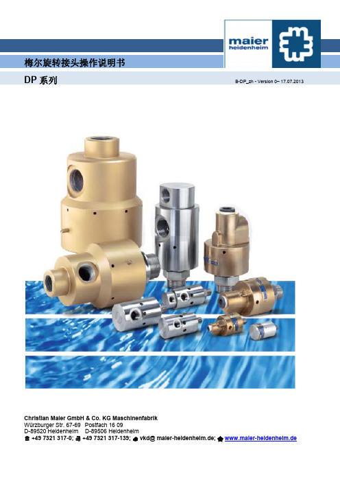
梅尔旋转接头操作说明书DP系列B-DP_zh - Version 0– 17.07.2013Christian Maier GmbH & Co. KG MaschinenfabrikWürzburger Str. 67-69 Postfach 16 09D-89520 Heidenheim D-89506 Heidenheim+49 7321 317-0; +49 7321 317-139; ***********************; www.maier-heidenheim.de梅尔旋转接头操作说明书DP系列B-DP_zh -Version 0 – 17.07.2013目录1 安全 (2)2 设计和功能 (3)3 设计和安装信息 (4)4 运输和储存 (4)5 安装 (5)6 操作 (7)7 维护 (8)本手册版权归Christian Maier GmbH & Co. KG所有。
本手册中包含的说明、信息和插图不得以任何方式进行全部或部分复制。
本手册中的说明、信息和插图也不得透露给任何第三方,或者用于制造同类竞争性产品、系统或者设备,或以任何方式协助此类活动。
梅尔旋转接头操作说明书DP 系列B-DP_zh -Version 0 – 17.07.20131. 安全目的梅尔旋转接头是一种专门用于连接压力管道和旋转压力系统的装置。
例如旋转压力系统是通过旋转接头向辊筒内部输送水或蒸汽。
该DP 系列旋转接头主要用于水。
DP...-800系列适用于载热油。
若是其他液体,请与厂家联系。
关于适用介质及其质量和性能,详情请参见“应用参数和备件”。
旋转接头应用中,不得超过手册中“应用参数和备件”规定数值。
切勿修改旋转接头,因为这可能会造成危害。
请务必按照操作手册中的说明来安装、操作和维护旋转接头。
对于一切未遵守操作说明而造成的损坏,我司概不负责。
这些操作说明中并不包含全部有关旋转接头安全操作的重要信息。
世伟洛克卡套接头手册
VCO® 和 VCR® 面密封接头
见世伟洛克 VCR 金属垫片面密封 接头和 VCO O 型 圈面密封接头目 录 (MS-01-24C4), P 130 和 (MS-01-28C4), P 150。
世伟洛克卡套管接头的优点
可检测卡套管接头和转换接头 7
卡套管接头
“在 10 000 多个接头中, 没有一个泄漏。”
卡套管接头
特点
■ 活动负载和双卡套设计。 ■ 易于安装。 ■ 安装时不会把扭矩传输到卡套管上。 ■ 世伟洛克® (Swagelok®) 间隙检测规确保了首次安装的充分紧固。
可检测卡套管接头和转换接头 3
卡套管
后卡套 铰链点
螺母 前卡套
接头本体
在装配具有先进几何形状设计特点的管接头时(如上图所 示), 前卡套被推入到接头本体和卡套管形成主密封, 而后卡 套向内产生铰链作用以对卡套管形成强有力的抓紧。后卡 套的几何形状有助于产生先进的工程铰链-夹箍作用, 这种 作用可把轴向运动转化为卡套管上的径向挤压作用, 操作时 只需要很小的装配扭矩。
可定位支管, SAE/MS 直螺纹 (TTS) 和可定位支管, ISO/BSP 平行螺纹 (TTR), 39
与世伟洛克卡套管 接头对接的 Kwik 夹具式法兰, 42
卡套管转换接头
卡套管转换接头信息, 43
外螺纹
NPT 和 ISO/BSP 锥形螺纹 (RT), 44
ISO/BSP 平行螺纹 (RS 和 RP), 45
世伟洛克根据 ASTM B117-95 标准进行 了有关测试, 以评估世伟洛克卡套管接头 的耐蚀性。
若需了解有关耐蚀性测试报告的更详细 信息, 请与您授权的世伟洛克代表联系。
混用/互换
这种做法可能存在危险。可以承受高压, 振动, 真空和温度变化的无泄漏密封需 要依赖于紧公差以及始终如一的, 严格 的质量控制和良好的设计原理。精密部 件的相互作用对于可靠性和安全性是至 关重要的。
90度弯管接头标准尺寸_解释说明以及概述

90度弯管接头标准尺寸解释说明以及概述1. 引言1.1 概述本篇文章旨在介绍和解释90度弯管接头的标准尺寸,以及对其进行概述。
随着工程设计和实际应用中对管道连接的需求日益增加,弯管接头作为一种重要的连接元件,在各个行业中得到了广泛的应用。
然而,不同行业或国家对于90度弯管接头的标准尺寸存在一定差异性,使得正确选择合适的标准尺寸成为一个具有挑战性的任务。
1.2 文章结构本文章共分为五个主要部分,包括引言、正文、弯管接头标准尺寸解释说明、弯管接头标准尺寸相关问题分析与讨论以及结论与总结。
在正文部分中将详细介绍弯管接头的定义及用途,以及标准尺寸的意义和作用,并探讨确定90度弯管接头标准尺寸的方法。
在弯管接头标准尺寸解释说明部分,将对直径和壁厚等考虑因素进行深入分析,并阐述设计原则和规范要求。
此外,还会针对常见标准尺寸进行举例,并解析其应用场景。
在弯管接头标准尺寸相关问题分析与讨论部分,将对不同行业或国家标准之间的差异性进行比较,并探讨特殊工况下标准尺寸选择的技术难题和解决方案。
最后,在结论与总结部分中,将对文章的主要内容和研究成果进行总结,并展望弯管接头标准尺寸的现状和发展趋势,并提出对于工程设计与实际应用的启示和建议。
1.3 目的本篇文章旨在通过对90度弯管接头标准尺寸的解释说明以及相关问题分析与讨论,揭示其重要性和复杂性。
通过深入了解各个行业或国家对于弯管接头标准尺寸的要求和规范,可以辅助工程设计师正确选择合适的标准尺寸,提高工程连接的安全性、可靠性和效率。
同时,也有助于发现并解决特殊工况下标准尺寸选择所面临的技术难题,并为未来对标准化尺寸改进和创新提供一些建议与探索方向。
2. 正文:2.1 弯管接头的定义及用途:弯管接头是一种常见的管道连接件,用于连接具有不同方向或角度的管道,并能够实现流体的顺畅传输。
弯管接头通常采用90度曲线形状,因此也被称为90度弯管接头。
其主要用途包括:在工业领域中应用于管道系统的安装和维修过程中,可以解决方向转换和管线布局上的问题;同时,在建筑领域中也被广泛应用于空调、暖通、给排水等系统。
管道弯头使用说明书
管道弯头使用说明书一、产品概述管道弯头是一种用于改变管道方向的管件,广泛应用于管道系统中。
本说明书将详细介绍管道弯头的使用方法和注意事项,确保用户能正确使用和安装管道弯头。
二、产品安装1. 在安装管道弯头之前,请确保管道系统已经排空和清洁,以防止杂质进入弯头内部影响使用效果。
2. 根据实际需要,选择合适的尺寸和型号的管道弯头。
3. 将管道弯头适配连接至管道系统的两端,确保紧密连接。
4. 使用扳手或工具适当拧紧连接螺纹,避免使用过大的力量造成损坏或渗漏。
三、产品使用注意事项1. 避免过度曲折:在使用管道弯头时,应避免过度曲折,以免影响管道流量和压力。
2. 注意流动方向:在安装管道弯头时,请确保流体的流动方向与弯头的设计一致,避免逆流造成压力损失。
3. 避免受力过大:对于曲线较小的弯头,应尽量避免受到过大的外力,以免弯曲变形或破裂。
4. 定期检查和维护:建议定期检查管道弯头的连接情况,如有松动或渗漏应及时处理。
同时,可以通过清洗管道系统来保持正常的流量和性能。
四、产品维护与保养1. 清洗:定期清洗管道弯头和整个管道系统内部,以防止杂质和积垢影响流量和效果。
2. 润滑:适当涂抹润滑剂,可以减少管道弯头的摩擦和磨损,延长使用寿命。
3. 外观检查:定期检查管道弯头的外观,如有损坏或腐蚀现象应及时更换或修理。
五、供应商信息如需要更多关于管道弯头的信息、技术支持或购买相关产品,请联系我们的客服中心:电话:XXX-XXXXXXX邮箱:***************地址:XXXXX市XXXX区XXXX街道X号六、免责声明本说明书旨在引导用户正确使用和安装管道弯头,但不对用户使用不当或违规操作造成的任何后果负责。
七、版权信息本说明书受版权保护,未经许可,不得擅自复制、转载或传播。
以上即是关于管道弯头使用的说明书,请用户在使用过程中遵守操作要求,如有疑问或需要进一步帮助,请随时联系我们的客服中心。
祝您使用愉快!。
软硬管接头设计说明书

机械制造工艺学基础课程设计课题名称:软硬管接头的设计班级:姓名:学号:指导老师:机械工程学院2011 年12 月课程设计任务书2011-2012学年第一学期机械工程学院机械工程及自动化专业机工091 班级课程名称:机械制造工艺学设计题目:软硬管接头的设计完成期限:自 2011年12 月 19日至 2011年12月27 日内容及任务设计内容:(一)对零件(中等复杂程度)进行工艺分析,画零件图。
(二)选择毛坯的制造方式。
(三)制订零件的机械加工工艺规程1.选择加工方案,制订工艺路线;2.选择定位基准;3.选择各工序所用的机床设备和工艺装备(刀具、夹具、量具等);4.确定加工余量及工序间尺寸和公差;5.确定切削用量(四)填写工艺文件1.填写机械加工工序卡片。
(五)编写设计说明书。
设计任务:掌握机械制造过程中的加工方法、加工装备等基本知识,提高学生分析和解决实际工程问题的能力,为后续课程的学习及今后从事科学研究、工程技术工作打下较坚实的基础。
每个学生应在教师指导下,独立完成以下任务:1. 零件图一张2.机械加工工序卡片一套;3.设计说明书一份。
进度安排起止日期工作内容2011.12.19-2011.12.20 熟悉课题、查阅资料2011.12.21-2011.12.22 零件分析,画零件图2011.12.23-2011.12.25 制订零件加工工艺规程2012.12.26-2011.12.27 填写工艺文件,编写设计说明书主要参考资料【1】张世昌,李旦主编,机械制造技术基础[M].北京:高等教育出版社,2006.1 【2】狄瑞坤,潘晓红主编.机械制造工程[M].杭州:浙江大学出版社,2001.1. 【3】杨梳子主编,机械机械加工工艺师手册.北京:机械工业出版社,2004.1【4】赵如福主编.金属机械加工工艺人员手册.上海:上海科学技术出版社,2006.11 指导老师(签字): 2011年12 月 29 日系(教研室)主任(签字): 2011 年 12 月 29 日目录第一章零件图样工艺性分析 (4)1接头的工作原理 (5)2零件图样分析 (5)3零件的工艺分析 (6)4确定软硬接头的生产类型 (7)第二章确定毛坯 (7)1确定毛坯的种类 (7)2确定锻件加工余量及尺寸公差 (8)3绘制锻件毛坯图 (10)第三章拟定的工艺加工路线过程 (10)1选择定位基准 (11)2表面加工方法的确定 (12)3加工阶段的划分 (12)4工序顺序的安排 (12)5确定工艺路线 (13)第四章选择加工设备和工艺设备 (13)1选择加工设备 (13)2选择工艺设备 (13)第五章工序的加工余量的确定、工序尺寸及公差的计算 (14)1圆柱表面工序尺寸 (15)2内孔工序尺寸 (15)3平面工序尺寸 (15)第六章确定切削用量 (15)第七章填写工艺过程卡和主要工序的工序卡 (24)第八章设计体会 (24)参考文献 (25)第一章零件图样工艺性分析1.接头的工作原理如图1所示为软硬管接头示意图,用于作为软管(橡胶管)和硬管(钢管)连接的中介材料,接头左端用于连接软管,右端外螺纹用于连接硬管,工作中有一定的流体冲击,所以左端需要开一个10cm长15度角的斜面来减缓冲击,同时外部与管子连接需要保证一定的配合。
塑料弯头注射模具设计说明书
塑料弯管注射模设计[摘要]这个设计的关键是对管接头注射模具的抽芯机构设计,介绍了一种成型90°塑料弯管接头注塑模的抽芯机构,阐述了该机构的工作原理,提出了主要零件的设计方法。
通过对塑件材料,质量体积的分析与计算,合理选用注塑机,并对各个参数进行了校核,设计出一副合理,经济,适用的塑料注塑模具。
[关键词]塑料弯管接头;注塑模;抽芯机构Pipe Joint Injection Molding and Die Machining Process DesignAbstract: The key to the design of pipe joints injection mold design core-pulling,An introduction is made on a special core-pulling mechanism which applied to the injection mould for the tie-in with 90°. And the working principle and the method of the design on the key components of the core-pulling mechanism are detailed analyzed. With the calculation of the plastics part, such as quantity and physical volume. Select the machine with reasonable method and adjust all of the parameter. The plastics inject molding will be design and keep with reasonable, economy and comfortable used.Key words:plastics tie-in; injection mould; core-pulling mechanism.目录引言 (1)1.成型工艺规程编制 (2)1.1塑件的工艺性分析 (2)1.1.1塑件原材料分析 (2)1.1.2塑件的结构和尺寸精度表面质量分析 (3)1.2计算制件的体积和质量 (4)1.3塑件注射工艺参数的确定 (4)2.模具结构的设计 (5)2.1分型面的选择 (5)2.2确定型腔的数量与排列方式 (5)2.3浇注系统和浇口套的设计 (6)2.3.1主流道设计 (6)2.3.2主流道衬套的形式 (7)2.3.3分流道的设计 (8)2.3.4浇口的设计 (9)2.3.5浇注系统的平衡 (11)2.3.6冷料穴的设计 (11)2.4抽芯机构设计 (12)2.4.1斜导柱抽芯机构 (12)3.模具成型零件结构设计 (15)3.1定模仁的结构设计 (15)3.2动模仁的结构设计 (16)4.顶出系统设计 (16)5.模具加热和冷却系统的设计 (17)6.模具闭合高度与注射机有关参数的校核 (19)7.模具的安装 (20)8.PROE在该模具的应用 (21)结论 ......................................................................................................... 错误!未定义书签。
水龙头用弯管模具设计手册

H H F-2 F-3 F-2 F-3 F-3
H H F-2 F-3 F-3 F-4 F-4
H H H F-2 F-2 F-3 F-3
H H F-2 F-2 F-3 F-4 F-4
N N H H F-2 F-2 F-3
N N H H F-2 F-3 F-4
注:a、选择虚线下面的方式进行弯管时,应配防皱板;b、N—表示可以不使用芯棒(即无芯弯管) ;c、H— 表示可以使用硬式芯棒弯管;d、F—表示需使用软式芯棒弯管,后面的数字为推荐的球节数。
第一章 弯管原理
弯管的成型方法一般有缠绕式、滚弯、外压、顶弯、拉弯等。本公司弯管机 主要采用缠绕式弯管工艺。 弯管工艺有冷弯与热弯,冷弯又分为无芯弯管和有芯弯管。本公司主要采用 有芯弯管的方式进行。 有芯弯管就是弯管与和通芯相结合的弯管工艺,其形成的弯角是按照弯内模 具的弯度形成的。操作过程是将弯管模固定在弯管机的主轴上,使之能够随主轴 进行旋转。管子在导板与夹紧块之间的共同作用下紧贴在弯管模上。为保证弯管 质量,防止其出现褶皱和断面的畸形,弯管模、通芯和防皱板与管子的外表面完 整吻合, 在外边压紧与内部芯棒的共同作用于完成弯折加工, 形成所需要的弯管。 工作原理图如图 1 所示。 图1 弯管机标准模具包括:弯管模(弯曲模块) 、夹紧块(夹紧模块) 、导板(导 板模块) 、通芯(通芯模块) 、防皱板(防皱模块)五部分组成,见图 2。 弯管模 管子 导板 防皱板
tx≥0.05 时, 采用无芯弯管即可; 当 Rx≤2.5, tx≥0.05 或 Rx≥3, 当 Rx≥3, tx≥0.025 时,使用硬式芯棒可达到预期的效果;当 Rx 和 tx 两者都较小而 弯曲角度α较大早,弯管过程中必须使用软式芯棒。
表 1
Rx
冷弯管补充设计说明

丰台区金汇中心(芳群园三区4号综合楼)补充设计说明设计单位:杭州中宇建筑设计有限公司审核人:编制人:工程概况:芳群园住宅区消防工程项目位于北京市丰台区方庄,总建筑面积28915.79平方米,主楼地上34层,地下3层。
主楼高度126.4米;裙房地上两层,地下一层,群芳高度9.90米。
补充设计说明:此楼房为圆形办公楼,由于楼内空间、施工技术等的限制条件,采用冷弯管对无缝钢管、不锈钢钢管和镀锌钢管采取再加工,所用钢管材料符合弯制标准,制作符合设计和标准的要求,满足压力管道安装的需要。
编制依据:《压力管道规范工业管道第4部分:制作与安装》GB/T20801.4-2006《油气输送用钢制弯管》SY/T5257-2004《设备控制程序》《检验与试验控制程序》《防腐控制程序》《材料、零部件控制程序》成型机理每根冷弯管都是通过弯制完成的。
将钢管置于弯管机上,弯管机对钢管施以弯曲力矩,使钢管局部发生适量变形,形成一定的角度,达到弯制目的,其基本过程是:后端夹具夹紧钢管(固定支点),然后通过前端下模主油缸的支点(活动支点)向上运动,使钢管沿上模曲线中部(固定支点)弯曲变形,直到弯制成型。
弯曲度为:11.25°制作程序1原材料要求1.1 用于制作冷弯管的管材必须符合国家标准的规定。
1.2用于弯制冷弯管的钢管应有钢管制造商质量证明书。
无标记、批号、质量证明书或质量证明书不全的钢管不能用于冷弯管制作加工。
1.3弯管用钢管表面应无油污杂物、无超标外观缺陷。
1.4 用于冷弯管弯制的钢管进入弯管场地后,应由弯管机组检验人员对外观和技术资料进行检查验收。
检验合格的钢管进入合格区。
对不合格的堆放在不合格区,同时由项目材料责任人负责与供货方办理退货的事宜。
2 冷弯管弯制2.1 一般规定1) 弯管机组技术人员应具有一定的冷弯管弯制施工经验。
2)弯管机操作工经过弯管机生产厂商技术人员的培训和本处的培训后,能熟练掌握弯管制作加工的操作技能。
弯管模具标准化手册
1---1 模具结构图
第1页,6页主视图
模具结构图
一套完整的弯管模具结构包括轮模、夹模、导模、芯棒
防皱板组成。
动作原理:芯棒进芯,夹模夹紧管材随轮模一起转动,导模压紧管材随着管材的弯曲而跟随,而防皱板固定不动,当弯管角度达到设定角度后,芯棒退出,夹模导模松开,复位完成整个动作。
1---1 轮模图
第2页平面图
1---1 夹模图
第3页平面图
1---1 导模图
第4页平面图
1---1 防皱板图
第5页平面图
防皱板标准化
防皱板主要用在薄壁(T≦1MM),管径(¢≧10MM)的管材上,主要防止管子弯曲处起皱。
防皱板一方面起着对管子支撑作用,另一方面围绕轮模相对滑动。
因此,防皱板需根据轮模半径设计
防皱板尺寸按图纸设计统一:其它尺寸按图纸零件设计
1---1 芯棒图
第6页平面图
芯棒标准化
1、芯棒尺寸按图纸设计统一:除以下尺寸外
A:根据原材料内径设计,一般比内径偏小0.5~0.8 B:根据原材料内径设计,一般比内径偏小0.2~0.5。
Victaulic Style 75 管道接头产品说明手册说明书

Exaggerated for clarityApprovals/ListingsSee Victaulic publication 10.01 for detailsSee Victaulic publication 02.06 for portable water approvals if applicable.Product DescriptionStyle 75 is available where moderate pressures areexpected or weight considerations are a factor. Upto 50% lighter in weight than the Style 77, the Style75 coupling is recommended for service up to 500psi/3450 kPa depending on size. Housings are cast intwo identical pieces in all sizes. Hot-dip galvanized andspecial coatings are available for all sizes.The Victaulic standard flexible coupling offering for grade“EHP” or “T” gaskets is the Style 177 installation-readyflexible coupling. For all available sizes, the Style 177 isthe standard flexible coupling Victaulic supplies in NorthAmerica for piping systems using Grade “EHP” or “T”gaskets. Contact Victaulic for further details.Performance data presented in this document is basedon use with standard wall, carbon steel pipe. For use withstainless steel pipe, please reference publication 17.09for pressure ratings and end loads. When used on lightwall stainless steel pipe, the Victaulic RX roll set mustbe used to roll groove the pipe. For further informationregarding roll grooving stainless steel, refer to publication17.01.NOTICE• Victaulic RX grooving rolls must be orderedseparately. They are identified by a silver color andthe designation RX on the front of the roll sets. Victaulic® Flexible CouplingStyle 7506.05Job/OwnerSystem No.LocationContractorSubmitted ByDateEngineerSpec SectionParagraphApprovedDateMaterial SpecificationsHousing:Ductile iron conforming to ASTM A-536, grade 65-45-12. Ductile iron conforming to ASTM A-395, grade 65-45-15, is available upon special request.Housing Coating: (specify choice)Standard: Orange enamel.Optional: Hot dipped galvanized and others. Gasket: (specify choice1)NOTE: Additional gasket styles are available. Contact Victaulic for details.G rade “E” EPDMEPDM (Green stripe color code). Temperaturerange –30ºF to +230ºF/–34ºC to +110ºC. May bespecified for cold and hot water service within thespecified temperature range plus a variety of diluteacids, oil-free air and many chemical services. ULClassified in accordance with ANSI/NSF 61 for cold+73ºF/+23ºC and hot +180ºF/+82ºC potable waterservice and ANSI/NSF 372. NOT COMPATIBLE FOR PETROLEUM SERVICES.G rade “T” NitrileNitrile (Orange stripe color code). Temperature range 20ºF to +180ºF/29ºC to +82ºC. May be specified for petroleum products, air with oil vapors, vegetableand mineral oils within the specified temperaturerange. Not compatible for hot water services over+150ºF/+66ºC or for hot dry air over +140ºF/+60ºC.1 S ervices listed are General Service Guidelines only. It should be noted thatthere are services for which these gaskets are not compatible. Reference should always be made to the latest Victaulic Gasket Selection Guide forspecific gasket service guidelines and for a listing of services which arenot compatible.Bolts/Nuts:Heat-treated plated carbon steel, trackhead meeting the physical and chemical requirements of ASTM A-449 and physical requirements of ASTM A-183Dimensions Style 75Nominal SizeActualOutsideDiameterMaximumWorkingPressure 2MaximumEndLoad 2Allow.Pipe EndSeparation3Deflection fromCenterline3Bolt/Nut4Dimensions Approx.WeightEachX Y Zinches mm inchesmmpsikPalbs.NinchesmmPer Cplg.DegreesPipeinches/ft.mm/m(No.) size inchesinchesmminchesmminchesmmlbs.kg1 251.31533.4500345068030250–0.060–1.62º–43’0.57482– 3/8 x 22.38614.271081.77451.30.61 1/4 321.66042.25003450108048050–0.060–1.62º–10’0.45382– 3/8 x 22.68684.611171.77451.40.61 1/2 401.90048.35003450142063200–0.060–1.61º–56’0.40332– 3/8 x 22.91744.821221.77451.50.62 502.37560.35003450221598600–0.060–1.61º–31’0.32262– 3/8 x 23.43875.221331.88481.70.82 1/2 652.87573.050034503245144400–0.060–1.61º–15’0.26222– 3/8 x 23.88985.681441.88481.90.976.1 mm 3.00076.150034503535157300–0.060–1.61º–12’0.26222– 3/8 x 24.001025.901501.88481.90.93 803.50088.950034504800213600–0.060–1.61º–2’0.22182– 1/2 x 2 3/44.501147.001781.88482.91.33 1/2 904.000101.650034506300280350–0.060–1.60º-54’0.19162– 1/2 x 2 3/45.001277.501911.88482.91.34 1004.500114.350034507950353800–0.130–3.21º–36’0.34282– 1/2 x 2 3/45.801478.032042.13544.11.9108.0 mm 4.250108.045031006380283950–0.130–3.21º–41’0.35292– 12 x 705.551417.791982.13543.71.74 1/2 1205.000127.045031008820392500–0.130–3.21º–26’0.25212– 5/8 x 3 1/46.131569.432402.13545.52.55 1255.563141.3450310010935486600–0.130–3.21º–18’0.27232– 5/8 x 3 1/46.8817510.072562.13545.82.6133.0 mm 5.250133.045031009735433250–0.130–3.21º–21’0.28242– 16 x 82.56.551669.372382.13546.02.7139.7 mm 5.500139.7450310010665474600–0.130–3.21º–18’0.28242– 5/8 x 3 1/46.801739.592442.13546.32.9152.4 mm 6.000152.4450310012735566700–0.130–3.21º–12’0.21182– 5/8 x 3 1/47.3818710.482661.88486.22.86 1506.625168.3450310015525690850–0.130–3.21º–5’0.23182– 5/8 x 3 1/48.0020311.072812.13547.03.2159.0 mm 6.250159.0450310013800614050–0.130–3.21º–9’0.24202– 16 x 82.57.6319410.492662.13546.83.18 2008.625219.14503100262801169450–0.130–3.20º–50’0.18142– 3/4 x 4 1/410.3426313.973552.135912.45.62 W orking Pressure and End Load are total, from all internal and external loads, based on standard weight (ANSI) steel pipe, standard roll or cut grooved inaccordance with Victaulic specifications. Contact Victaulic for performance on other pipe.3 A llowable Pipe End Separation and Deflection figures show the maximum nominal range of movement available at each joint for standard roll grooved pipe.Figures for standard cut grooved pipe may be doubled. These figures are maximums; for design and installation purposes these figures should be reduced by: 50% for 3/4 – 3 1/2”/20 – 90 mm; 25% for 4”/100 mm and larger.4 N umber of bolts required equals number of housing segments.General NotesMetric thread size bolts are available (color coded gold) for all coupling sizes upon request. Contact Victaulic for details.WARNING: FOR ONE TIME FIELD TEST ONLY, the Maximum Joint Working Pressure may be increased to 11/2 times the figures shown.InstallationReference should always be made to the I-100 Victaulic Field Installation Handbook for the product you are installing. Handbooks are included with each shipment of Victaulic products for complete installation and assembly data, and are available in PDF format on our website at .WarrantyRefer to the Warranty section of the current Price List or contact Victaulic for details.NoteThis product shall be manufactured by Victaulic or to Victaulic specifications. All products to be installed in accordance with current Victaulic installation/assembly instructions. Victaulic reserves the right to change product specifications, designs and standard equipment without notice and without incurring obligations.TrademarksVictaulic® is a registered trademark of Victaulic Company.。
手动弯管器使用手册说明书

2Table of ContentsIntroduction . . . . . . . . . . . . . . . . . . . . . . . . 4 Tubing Data . . . . . . . . . . . . . . . . . . . . . . . . 4 Tubing Installation . . . . . . . . . . . . . . . . . . . 6 Product Information . . . . . . . . . . . . . . . . . 7 Vise Clamp Block . . . . . . . . . . . . . . . . . . . 8 Bend Layout . . . . . . . . . . . . . . . . . . . . . . . . 9 Using the Bender . . . . . . . . . . . . . . . . . . . 12 Making Bends . . . . . . . . . . . . . . . . . . . . . 15 Reverse Bends . . . . . . . . . . . . . . . . . . . . . 18 Springback . . . . . . . . . . . . . . . . . . . . . . . . 19 Determining Changes inPlane and Direction . . . . . . . . . . . . . . . . . 20 Adjustment (Gain) Calculations . . . . . . . 21 Troubleshooting . . . . . . . . . . . . . . . . . . . . 24 Replacement Parts . . . . . . . . . . . . . . . . . 263IntroductionSwagelok® hand tube benders provide consistent,high‑quality bends in tubing made from most materials used with Swagelok tube fittings .Read this manual before using the hand tube bender .About SwagelokHeadquartered in Solon, Ohio, U .S .A ., SwagelokCompany is a major developer and provider of fluidsystem solutions, including products, assemblies,and services for the research, instrumentation,pharmaceutical, oil and gas, power, petrochemical,alternative fuels, and semiconductor industries . Ourmanufacturing, research, technical support, anddistribution facilities support a global network of 225 sales and service centers in 70 countries .For more information or assistance please contactyour authorized Swagelok sales and service center or visit our website at www .swagelok .com .Tubing Data■ The Swagelok hand tube bender bends 1/8, 1/4, 5/16,3/8, and 1/2 in ., and 3, 6, 8, 10, and 12 mm outsidediameter tubing in a variety of wall thicknesses .■ T ubing should be free of scratches and suitable forbending .4Tubing DataSuggested Tubing Ordering Information Fractional TubingHigh‑quality, soft‑annealed, seamless carbon steel hydraulic tubing ASTM A179 or equivalent . Hardness 72 HRB (130 HV) or less .Fully annealed, high‑quality (Type 304, 316 etc .) (seamless or welded and drawn) stainless steel hydraulic tubing ASTM A269 or A213, or equivalent . Hardness 90 HRB (200 HV or less) .Metric TubingHigh‑quality, soft‑annealed, carbon steel hydraulic tubing DIN2391 or equivalent . Hardness 130 HV (72 HRB) or less .Fully annealed, high‑quality (Type 304, 316 etc .) stainless steel tubing EN ISO 1127 or equivalent .5Tubing InstallationProperly selected tubing, combined with qualitySwagelok tube fittings, can provide leak‑tightsystems .When installing fittings near tube bends, there must be a sufficient length of straight tubing to allow thetube to be bottomed in the Swagelok tube fitting:67Product InformationClevis LinkRoll diesBender dieVise clamp blockName plateTube latchRoll supportLong handle Short handleName plate Straight tubeVise Clamp BlockThe Swagelok hand tube bender features a vise clamp block which allows the bender to be clamped in avise . This feature is helpful when bending tube of ahard material or heavy wall thickness, or long piecesof tubing that need to be supported .8Bend LayoutThis bender can be used to form single, offset, and other bends . This section contains information for measuring and marking the tube prior to bending . Note: Make all marks 360° around the tube .The Measure-Bend Method1 . Estimate the overall length of tubing required byadding the length of all the sections together .2 . Place a reference mark at the end of the tubefrom which you are beginning the measurement .3 . Measure from the reference mark and make abend mark on the tube at a distance equal tothe desired bend length . This mark indicates thevertex of the bend .4 . See Using the Bender, page 12, to bend thetube .5 . For additional bends, use the vertex of theprevious bend as the reference mark, repeatsteps 3 and 4 for the next bend . (The vertexis where the center lines of the two legs of theangle intersect .)An example appears on the next page .910E xample of the measure‑bend method:A 90° bend 4 inches from the reference mark followed by a 45° bend with 4 inches between bends .1 . Place a reference mark at the end of the tubefrom which you are beginning the measurements .2 . Measure 4 in . from the reference mark and makea bend mark to indicate the first desired bendlength .3 . Bend the tube 90° as described in Using theBender, page 12 .4 . M ake a second bend mark 4 in . from the vertexof the 90° bend, away from the reference mark .5 . Place a directional mark over the bend markto indicate the outside, or heel, of the 45° bend .This will help ensure the bend is made in theintended direction .6 . Bend the tube 45° as described in Using theBender, page 12 .Offset Bend FormulaCUsing the Bender1 . Swing the short handle up so it is above thebender die .2 . Open the tube latch .3 . P lace the tube in the groove of the bender diewith the reference mark to the left of the tubelatch .4 .C lose the tube latch over the tube just enoughto hold the tube in place . This restricts movement of the tube during initial positioning but stillallows for additional alignment .5 . C arefully lower the short handle until the rolldies rest gently on the tube while keeping the link straight and parallel to the long handle . Note: P remature bending may occur if the linkis not straight and parallel to the longhandle .6 . A lign the zero on the roll support with the zeroon the name plate .markShown aligned for a 90° bend.7 . Align the bend mark with the mark on the rollsupport that corresponds to the bend angle .Note: V iew the marks on the hand tube bender as a 0 to 90° scale when bending otherangles .8 . P ush the tube latch firmly over the tube tosecure the tube in the bender die .Note: E xcessive pressure on the tube latch may damage soft tubing .Making BendsBends 90° or Less1 . S lowly push the short handle down until the 0on the roll support reaches the desired degree mark on the name plate .Note: B e aware of springback, described onpage 19 .2 . After completing the bend, swing the shorthandle up and away from the tube .3 . Pull the tube latch off the tube and remove thetube from the bender groove .Bends Greater than 90°The right‑angle design of the Swagelok hand tube bender offers maximum leverage when making bends . The bender’s unique design lets you continue using right angle leverage for bends greater than 90° .1 . S lowly push the short handle down until the 0on the roll support reaches approximately 90°on the name plate .2 . L oosenclevis untilthe short handle will swing without moving the roll support .3 . Swing the short handle up until it is slightlyabove perpendicular to the long handle .4 . Retighten the short handle . This will providecontinuous right‑angle leverage for the rest of the bend .5 . Continue the bend until the 0 on the roll supportreaches the desired degree mark on the name plate .6 . A fter completing the bend, swing the shorthandle away, pausing when the 0 on the roll support reaches approximately 90° . Loosen the short handle, move it until parallel with the long handle, then retighten the short handle .7 . Move the short handle up and away from thetube .8 . Pull the tube latch off the tube and remove thetube from the bender groove .Name plateReverse BendsThe Measure-Bend MethodSometimes a multiple bend layout will require that a bend be made in reverse . A reverse bend is made with the reference mark to the right of the tube latch .1 . Align the bend mark with the marks on the rollsupport as follows:■ 90° bends line up under the R mark■F or other bend angles, treat the marksbetween 0 and R as an approximate 0 to 90Shown aligned for a 90° reverse bend.2 . Bend the tube as described in Making Bends,page 15 .SpringbackAll tubing will exhibit springback after a bend has been completed . The amount of springback depends on the bend angle, bend radius, tubing material, and wall thickness .Experience will help you predict the amount of springback . Expect to allow 1 to 3° of compensation . Note : V erify the bend angle using a template,protractor or against a known angle to ensurethe desired bend angle has been achieved .Note: D o not bend all the way to the bend mark when bending softer tubing such as copper oraluminum .Determining Changes in Plane and DirectionWhen making multiple bends on a single piece of tube, make sure the bend is made in the correct direction .For bends in the opposite direction of the previous bend, align the tube with the raised short handle (plane A) .Plane APlane B21Adjustment (Gain) CalculationsWhen determining tube bend location, adjustment (gain) factors can be considered as an alternate way to achieve the desired layout .Adjustment is the difference in the length of tubing used in a radiused bend compared to the length of tubing required in a sharp bend, when measured from the beginning to the end of the bend .Note: T he distance around a radiused bend is alwaysless than a sharp bend .EndBeginningEndSharp BendCrawford Hand Tube Bender MS‑13‑43 C‑ELD‑334 Example1/4 in . tubing using a 1/4 in . bender with a 9/16 in .bend radius .To achieve the desired bend, mark the tubing asfollows:P1 = 3 in .To determine the location of the bend mark for asubsequent bend, add the new section leg length tothe previous bend mark location, then subtract theadjustment (gain) of the previous bend .P2= P1 + 2 .5 in . – 5/16 in . adjustment = 5 3/16 in .P3= P2 + 3 in . – 5/16 in . adjustment = 7 7/8 in .7 7/8 inches is the total length of tube needed .90° adjustment= 5/16 in .Bend the tube as described in Using the Bender,page 12 .22Fractional Adjustment CalculationsMetric Adjustment Calculations23Troubleshooting242526Replacement PartsHand Tube Bender Components11025346789121113141516100107L (4 a n d 4T o n l y )27Repair KitsRepair kits contain a link, shoulder screws, spring washers, thread locking adhesive, a safety dataGrip KitsGrip kits contain two handle grips .28Roller SubassembliesA roller subassembly contains a roll support, clevis, roll dies, clevis pin, and lock dowels assembled29Hand Tube Bender ComponentsThese components may be ordered individually .30➀O rdering number for shoulder screw to be used with a link not containing a counterbore .LinkCounterbore Link➁O rdering number for shoulder screw to be used with a link containing a counterbore .31Swagelok—TM Swagelok Company © 2009–2022 Swagelok Company Printed in U .S .A ., AGSMS‑13‑43 RevG, December 2022。
世伟洛克 卡套管工具和附件产品(ms-01-179c4r3) 说明书
尺寸 代号
6M 10M 12M 14M 15M 16M 18M 20M 22M 25M 28M 30M
手动弯管机
世伟洛克手动弯管机能对 可与世伟洛克卡套管接 头配合使用的卡套管 进行一致的、高质量的 弯曲。
特点
■ 手动弯管机能弯曲的卡套管尺寸为 1/4、5/16、3/8 和 1/2 in. 以及 6、8、10 和 12 mm。
特点
■ 特殊设计的夹子能准确地夹持住卡套管,而不会使卡套管 表面变形或产生划痕。
电动—110 V (ac)
MS-BTB-1
电动—230 V (ac)
MS-BTB-2
例如:MS-BTB-1
2. 添加一电源线➀ 代号(电动型)。
地区 北美
日本 / 台湾
英国
欧洲 / 韩国 澳大利亚 /
Байду номын сангаас新西兰
电压
插头 类型 电线类型 电源线代号
110 / 120 V (ac) NEMA
50 / 60 Hz
IEC-309
-5
同上
220 / 240 V (ac) 50 / 60 Hz
BS 1363
-6
220 / 240 V (ac) 50 / 60 Hz
CEE 7 / 7
-7
220 / 240 V (ac) 50 / 60 Hz
AS 3112
-8
例如:MS-BTB-1-1
➀ 如需了解详细信息,请参见世伟洛克电源线和插头选购件目录, MS-02-79。
弯管机
台式弯管机
特点
■ 牢固、重量轻的铝合金结构 ■ 弯曲范围 1 至 180° ■ 卡套管外径范围为 1/4 至 1 1/4 in. (0.028 至 0.120 in. 壁厚)
【CN210167755U】一种弯管接头【专利】

(19)中华人民共和国国家知识产权局(12)实用新型专利(10)授权公告号 (45)授权公告日 (21)申请号 201920583382.3(22)申请日 2019.04.25(73)专利权人 广州吉码电子科技有限公司地址 510700 广东省广州市高新技术产业开发区科学城掬泉路3号广州国际企业孵化器A区A1101号(72)发明人 毕惠英 (74)专利代理机构 广州三环专利商标代理有限公司 44202代理人 颜希文 黄华莲(51)Int.Cl.H02G 3/06(2006.01)(54)实用新型名称一种弯管接头(57)摘要本实用新型提供了一种弯管接头,其包括弯头、第一管接件、第二管接件、第一限位件和第二限位件,弯头包括第一主体部和与第一主体部一体化结构的第二主体部,第一主体部和第二主体部倾斜连接,第一主体部和第二主体部均设有通孔,第一主体部的内表面和第二主体部的内表面均设有内螺纹;第一管接件和第二管接件均设有通孔,第一管接件的外表面和第二管接件的外表面均设有与内螺纹螺纹连接的外螺纹;第一限位件固定连接于第一管接件的外表面,第二限位件固定连接于第二管接件的外表面。
本实用新型能解决现有技术中摄像头线路的固定和摄像头与其它部件的固定具有安装不便和影响工作人员对罐体的检查工作的问题。
权利要求书1页 说明书4页 附图1页CN 210167755 U 2020.03.20C N 210167755U权 利 要 求 书1/1页CN 210167755 U1.一种弯管接头,其特征在于,包括弯头、第一管接件、第二管接件、第一限位件和第二限位件,所述弯头包括第一主体部和与所述第一主体部一体化结构的第二主体部,所述第一主体部和所述第二主体部倾斜连接,所述第一主体部和所述第二主体部均设有通孔,所述第一主体部的内表面和所述第二主体部的内表面均设有内螺纹;所述第一管接件和所述第二管接件均设有通孔,所述第一管接件的外表面和所述第二管接件的外表面均设有与所述内螺纹螺纹连接的外螺纹;所述第一限位件固定连接于所述第一管接件的外表面,所述第二限位件固定连接于所述第二管接件的外表面,所述第一限位件为第一限位凸起,所述第一限位凸起的外径大于所述第一主体部的内径,所述第二限位件为第二限位凸起,所述第二限位凸起的外径大于所述第二主体部的内径,所述第一限位件设于所述第一管接件的中部,所述第二限位件设于所述第二管接件的中部;所述第一主体部和所述第二主体部的夹角为90°~135°,所述第一主体部的内径与所述第二主体部的内径相等。
管道设计说明范本(精)
目录1.设计说明 (04)1.1工程概况 (04)1.1.1 概述 (04)1.1.2各信息点种类、分布及数量表 (04)1.2设计依据 (04)1.3设计范围......................................................................... (05)1.4设计方案的确定 (05)1.4.1 应达到的设计目的 (05)1.4.2 机房位置设置 (05)1.4.3 配线架和缆线设计建议 (05)1.4.4系统构成 (06)1.4.5 工作区子系统布线 (06)1.4.6配线(水平)子系统 (06)1.4.7建筑物主干子系统 (06)1.4.8管理子系统 (07)1.5主要工程量表及设备配置、缆线计算 (07)1.6测试指标 (10)1.6.1电缆系统测试方法 (10)1.6.2电缆系统测试参数 (11)1.6.3光缆系统测试方法 (13)1.6.4光缆系统测试参数 (14)1.7安装施工要求 (14)1.7.1管道建设 (14)1.7.2管槽安装、敷设 (15)1.7.3电缆敷设 (15)1.7.4光缆敷设 (16)1.7.5配线管理系统 (17)1.7.6机架的安装 (17)1.7.7缆线端接 (17)1.7.8地线安装 (18)1.8其他需要说明的问题 (18)2.概预算编制说明 (20)2.1概述及概预算总额 (20)2.2概预算编制依据 (20)2.3有关费用的取定标准及计算方法 (21)2.4投资分析......................................................................... . (21)2.5其他有关需要说明的问题 (21)3.概预算表3.1概、预算总表(表一)…………………………………..……....………..…第全页3.2建筑安装工程费用概、预算表(表二)……………. ……..……..…..…第全页3.3建筑安装工程量表概、预算表(表三甲)…..…………..….…………第1-2页3.4国内主要材料预算表(表四)甲………………………..……………..…第1-5页3.5建设其它费用预算表(表五)……………………... ..……………..….….第全页4.图纸部分4.1 XXXXXXXXXXXXXXXXXXXXXXXXXXX………..……………….…........….….. BX-014.2 XXXXXXXXXXXXXXXXXXXXXXXXXXXXXXXXXX………..………..…...….….. BX-02 4.3 XXXXXXXXXXXXXXXXXXXXXXXXXXXXXXXXXX………………………...….... BX-03 4.4 XXXXXXXXXXXXXXXXXXXXXXXXXXXXXXX………………..…..…..…...……. BX-041.设计说明1.1概述本工程为xxxxxxx省xxxxxx电信局xxxx路新建通信管道工程一阶段设计,管道全长xxx管公里,其中:xxx孔平{立}型塑料管道xxxx管公里;xxx孔平立型钢管管道xxxx 管公里。
- 1、下载文档前请自行甄别文档内容的完整性,平台不提供额外的编辑、内容补充、找答案等附加服务。
- 2、"仅部分预览"的文档,不可在线预览部分如存在完整性等问题,可反馈申请退款(可完整预览的文档不适用该条件!)。
- 3、如文档侵犯您的权益,请联系客服反馈,我们会尽快为您处理(人工客服工作时间:9:00-18:30)。
夹具设计
课程设计说明书
设计题目
设计弯管接头夹具
班级11422 班
学号05号
学生陈娟
指导教师刘平
成都工业学院机电工程系
2013年10 月12 日
目录
1 工件图纸与夹具设计任务的分析……………………………. 2工件加工工艺过程分析…………………………………..........
2.1 表面加工方法的确定....................................................
2.2加工工艺路线的确定…………………………………......
3选用机床的型号与主要参数…………………………………….. 4确定定位方案与设计定位装置………………………………..
4.1确定工件加工需要限制的自由度………………………...
4.2 定位方案的确定……………………………………..........
4.3 定位机构设计…………………………………………….. 5确定夹紧方案与设计夹紧装置……………………………….. 6设计夹具总体设计……………………………………………..
6.1夹具体……………………………………………………. 7主要尺寸公差配合与技术要求的制定……………………….. 8小结…………………………………………………………….. 9参考文献………………………………………………………..
1、工件图纸与夹具设计任务的分析
如图所示,弯管接头工件,根据题目所给条件该工件除M42×3外螺纹、外圆和2×1的退刀槽3处外,其余表面已经加工到设计要求。
精度要求较高的Φ60 0-0.046外圆已经加工完成,本工序要求加工M42×3外螺纹、外圆和2×1的退刀槽3处,加工后既要保证外圆的尺寸精度,又要保证外圆、M42×3外螺纹的表面粗糙度。
2、工件加工工艺过程分析
2.1 表面加工方法的确定
(1)加工M42×3外螺纹:表面粗糙度为Ra6.3,查参考文献一P107表4-11可知,分为粗车——半精车两次加工完成φ42外圆,再车螺纹。
(2)加工2×1的退刀槽:无表面粗糙度,粗车一次即可达到要求;
(3)加工外圆:表面粗糙度为Ra3.2,查参考文献一P107
表4-11可知,分为粗车——半精车——精车三次加工;
2.2加工工艺路线的确定
(1)粗车外圆φ42到尺寸;半精车外圆φ42到尺寸
(2)根据工件外圆的特点和加工要求确定加工路线为:粗车外圆到尺寸;半精车外圆到尺寸;精车外圆到尺寸。
(3)车退刀槽到尺寸φ28;
(4)车螺纹到尺寸M42×3。
各工序加工余量的确定
查《机械加工实用手册》P250表5.2.12知,此零件毛坯直径总余量为2mm。
半精车加工余量为1.1mm;精车加工余量为0.25mm;所以粗车加工余量为2-1.1-0.25=0.65mm。
各尺寸公差确定
查《数控加工工艺》P109知,粗车经济精度为IT11~13取IT12,查《机械设计课程设计手册》P104表9-1知,Φ30mm轴的尺寸公差为0.21mm,Φ42mm轴的尺寸公差为0.25;查《数控加工工艺》P109知半精车经济精度为IT8~IT11取IT9,查《机械设计课程设计手册》P104表9-1知Φ30mm轴的尺寸公差为0.13,Φ42mm轴的尺寸公差为0.16。
各工序的基本尺寸计算如下
对于Φ30mm轴,精车D=30mm,半精车D=30+0.25=30.25mm,粗车D=30+1.1=31.1mm;
对于Φ42mm轴,精车D=42mm,半精车D=42.25mm,粗车D=43.1mm 最终得到各工序尺寸及偏差为
Φ30mm轴,精车,半精车Φ30.25-0.130,粗车Φ30.1-0.210
Φ42轴,粗车Φ420.160,半精车Φ42-0.130。
3、选用设备的型号与主要参数
3.1机床的选择与主要参数
根据弯管接头工件的尺寸大小、形状和加工要求,查参考文献二P901表3-12-1 选择C620型普通车床为加工设备。
C620型普通车床的主要参数:
3.2刀具的选择
根据被加工表面的技术要求,查资料可得:加工外圆、φ42外圆选用90度硬质合金外圆车刀,加工退刀槽选用切断刀,加工螺纹选用60度硬质合金螺纹车刀。
4、确定定位方案与设计定位装置
4.1确定工件加工需要限制的自由度
根据弯管接头工件加工要求以平行于A 面方向为X 轴,分析加工外圆、螺纹、退刀槽所需限制的自由度,并将结果列入表1:
表1 加工外圆、螺纹、退刀槽需要限制的自由度表
序号 加工要求保证尺寸和形位精度
需要限制的自由度 1
Φ60 0-0.046外圆 X 、Y 、X 、Y 2
A 面 Z 3 Φ7孔
Z 机床型
号 顶尖距离L 中心高H
加工最大直径 刀具支持面至主轴中心线高度M 刀 架 最大行程 小刀架转角 在床面
以上 在横刀架以上 纵向 横向 小刀架
C620 750 1000 200 400 210 25
650 900 250 280
100 45
4.2 定位方案的确定
根据以上分析,以A面限制一个自由度,Φ60 0-0.046外圆限制4个自由度,Φ7孔限制一个自由度。
4.3 定位机构设计
根据所确定的定位方案设计定位机构如图
由带孔支承板、花盘、过渡盘衬套及削边销组成定位机构。
查参考文献二P300选用GB2203-80型削边销,削边销与Φ7孔配合为过盈配合,配合公差为H7/n6。
削边销尺寸计算如下:
如图所示:D=7 ,H=12 ,d=10 ,D1=11 ,L=20 ,h=3 ,
B=D-1=6。
4.3.1尺寸80+-0.1 的定位误差计算
由于该尺寸的设计基准和定位基准均为A面,为基准统一的定位方式,
因此,基准不重合误差:0
∆
=
B
由于定位基准为加工后的平面,因此基准位移误差:0
∆
=
Y 所以该尺寸的定位误差:0
=
∆
∆
+
=
∆
D
Y
B
5、确定夹紧方案与设计夹紧装置
根据工件的定位加工和加工条件,采用普通平压板夹紧工件。
采用螺栓连接,普通平压板可以在一定范围内移动,便于拆卸。
压板为标准件,查参考文献二P407选用GB2175-80型移动压板,公称直径=12mm、长L=80mm。
6、夹具的总体设计
在以上各步的基础上,进行夹具总体结构的设计:并绘制总体结构图,见装配图。
6.1夹具体
根据以定位、夹紧装置的布局,综合考虑夹具的工作可靠性、使用方便性以及制造的经济性等方面的因素,将夹具体设计为单支承结构的整体铸造结构,材料选用HT300,为了增强立板的刚性,采用
了双肋板。
在夹具体上方设计平衡块,以保证夹具体的平衡性。
为了保证在装配过程中方便确定排屑槽位置和在夹紧过程中心轴不会产生转动,在心轴与夹具体的配合部分设计了定位键。
7、主要尺寸公差配合与技术要求的制定
在完成夹具总体设计后,要进行夹具主要尺寸公差等技术要求的确定。
本夹具的主要尺寸公差配合与技术要求如装配图所示。
现将制定的理由说明如下:
查参考文献二衬套与夹具体的配合公差为H7/n6;
削边销与夹具体的配合公差为H7/h6,与工件的配合公差为H7/f6;
花盘与过渡盘之间的配合公差为H7/k6;
工件与衬套之间的配合公差为H7/h6
8、小结
通过一周的学习,我学到到了很多以往在课堂学习中未
吸收到的知识,在课上无法做到时时刻刻的集中注意力听
讲,对学过的知识难以学以致用,当谈及到实践操作时,我
们往往望而却步。
但是通过本周的训练,我的知识面、动手
能力等都有所提高,这一周的实践,我们的时间虽然有些紧
张、有些苦有些累,但是也是值得的,因为通过这一周的动
手学习我有很大收获和提升,虽然在整个过程遇到了很多困
难,但是我们坚持查资料把不懂的知识学会,最终专周得以
圆满完成,我们的实践学习补充了专科生在理论知识上与本科的差距,我们不再是只会纸上谈兵的赵括,我们懂得学以致用,总之,这一周的学习使我们又向专业人士迈进了一步,离成功又近了一步。
9、参考文献
(1).李华志. <数控机床加工工艺.> 哈尔滨. 哈尔滨工程大学出版社(2)王光斗王春福.<机床夹具设计手册>.山东.山东科学技术出版
社
(3)王晓丽. <机械制图.> 北京. 科学技术出版社
(4)李名望.<机床夹具设实例教程>.化学工业出版社。
