诺瓦科技LED视频处理器VX6s用户手册
诺瓦科技LED多媒体播放器快速使用指南
声明
欢迎您选用西安诺瓦电子科技有限公司(以下简称诺瓦科技)的产品,如果本文档为您了解和使用产品带 来帮助和便利,我们深感欣慰。我们在编写文档时力求精确可靠,随时可能对内容进行修改或变更,恕不 另行通知。如果您在使用中遇到任何问题,或者有好的建议,请按照文档提供的联系方式联系我们。对您 在使用中遇到的问题,我们会尽力给予支持,对您提出的建议,我们衷心感谢并会尽快评估采纳。
2 操作准备
2 操作准备
2.1 获取与安装软件
类别 ViPlex Handy
说明
获取方式
安装方式
局 域 网 显 示 屏 管 理 软 扫描下面的二维码,下载 件,包括 Android 版和 APP 并安装。 iOS 版,主要用于管理显 示屏,编辑和发布节 目。
软件安装 方式与一 般应用软 件的安装 方式相 同。
Taurus 系列多媒体播放器 快速使用指南
2.1 获取与安装软 件 ........................................................................................................................................... 2
ViPlex Express: 步骤 1 请参见“6.2 通过 ViPlex Express 登录 Taurus (Windows 版)”,登录 Taurus 。 步骤 2 单击界面右上角的 并选择“DHCP 服务”。 步骤 3 开启 DHCP 服务,为 Taurus 自动分配 IP 地址。
3.3 WiFi 连 接 ..................................................................................................................................................... .4 3.3.1 WiFi AP 模 式........................................................................................................................................ ...... 4 3.3.2 WiFi Sta 模 式 ....................................................................................................................................... ...... 5 3.3.3 WiFi AP+Sta 模 式 ...................................................................................................................................... 6
诺瓦科技LED视频控制器VX6s规格书英文版

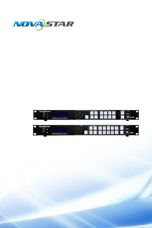
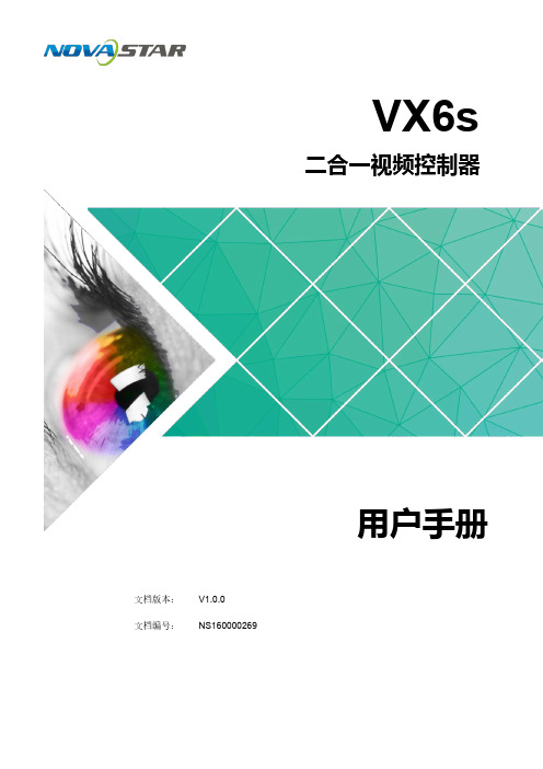
VX6sAll-in-One Video ControllerDocument Version: V1.0.0Document Number: NS160100264SpecificationsXI'A NN O VAS TA RT E CH CO.,L T D .Copyright © 2018 Xi’an NovaStar Tech Co., Ltd. All Rights Reserved.No part of this document may be copied, reproduced, extracted or transmitted in any form or by any means without the prior written consent of Xi’an NovaStar Tech Co., Ltd.Trademarkis a trademark of X i’an NovaStar Tech Co., Ltd.StatementYou are welcome to use the product of Xi’an NovaStar Tech Co., Ltd. (hereinafter referred to as NovaStar). This document is intended to help you understand and use the product. For accuracy and reliability, NovaStar may make improvements and/or changes to this document at any time and without notice. Any problem in use or any good suggestion, please contact us through ways provided in the document. We will do our utmost to solve the problems and adopt the suggestions after evaluation as soon as possible. Website: www.novastar.techX I 'A NN OV AS TA RT EC HC O.,LT D.1 Overview The VX6s is an all-in-one video controller that integrates sending card functions with video processing. Designed with powerful video processing capability, it supports 7 video inputs and 6 Gigabit Ethernet outputs.Based on the powerful FPGA processing platform, the VX6s supports multiple switching effects, such as quick seamless switching and fade, providing flexible screen control experience and outstanding video presentations.X I 'A NN OV AS TA RT EC HC O.,LT D.2 Features●Features 7 input connectors: 2 × 3G-SDI, 2 × HDMI1.3, 2 × DVI, 1 × USB.●Supports 3 × layers and 1 × OSD.●Supports quick and advanced screen configurations.●Switches the PVW to PGM by pressing only the TAKE button in the switchermode.●Supports PGM preview in the switcher mode.●Supports adjustment of input resolutions and backup of input source.●Supports brightness adjustment of the screen loaded by the VX6s.●Multiple VX6s units can be cascaded.●Automatically scales the image to fit the whole screen.●The maximum video output width is 4096 pixels.● A total of 16 user presets can be created and saved as templates. The templatescan be used directly and conveniently.●Any HDMI or DVI input source can be used as the synchronization signal toachieve vertical synchronization of output.●Features an intuitive OLED screen and clear button indicator lights in the frontpanel, simplifying system control and operation.X I 'A NN OV AS TA RT EC HC O.,LT D.3 Appearance Front PanelX I 'AC HC O.,LT D.Rear PanelXI'A .,LX I 'A NN OV AS TA RT ECSpecifications 4 Dimensions4 DimensionsUnit: mmX I 'A NN OV AS TA RT EC HC O.,LT D.Specifications 5 Applications5 ApplicationsX I 'A NN OV AS TA RT EC HC O.,LT D.。
多屏拼接LED视频处理器诺瓦科技VX系列连接方法用户手册

视频控制器VX系列产品用户手册声明欢迎您选用西安诺瓦电子科技有限公司(以下简称诺瓦科技)的产品,如果本文档为您了解和使用产品带来帮助和便利,我们深感欣慰。
我们在编写文档时力求精确可靠,随时可能对内容进行修改或变更,恕不另行通知。
如果您在使用中遇到任何问题,或者有好的建议,请按照文档提供的联系方式联系我们。
对您在使用中遇到的问题,我们会尽力给予支持,对您提出的建议,我们衷心感谢并会尽快评估采纳。
版权本文档版权归诺瓦科技所有,未经本公司书面许可,任何单位或个人不得以任何形式对文本内容进行复制、摘录等,违者必究。
商标是诺瓦科技的注册商标。
安全声明为避免可能的危险,请按规定使用此设备。
如出现损坏,非专业人士请勿擅自打开维修,请及时与本公司售后联系。
高压危险:本产品的工作电压为100~240V AC。
接地:本产品通过电源的地线与大地相连,请确保接地导体的良好接地。
电磁干扰:设备应远离磁铁、马达及变压器。
防潮:请将设备置于干燥、干净的环境中。
如有液体浸入,请立即拔掉电源插头。
远离易燃易爆危险物品。
禁止液体、金属碎片浸入机器内部,以免引起安全事故。
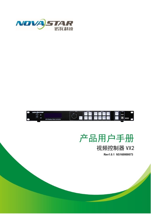
目录1型号说明 12外观说明 1前面板 1后面板 2 3信号连接 54安装尺寸 55操作动作说明 66主界面 67菜单操作 7第一步输入设置 7 第二步快捷点屏 8 第三步亮度调节 9 第四步输出设置 9 拼接带载 11 高级设置 12 U 盘播放设置 17 工厂复位 17 通讯设置 17语言设置 18 8技术规格 189常见问题 191 型号说明型号描述VX2输入接口:1 路 DVI,3 路 VGA,2 路 CVBS,1 路 HDMI,1 路 DPVX2U输入接口:1 路 DVI,2 路 VGA,2 路 CVBS,1 路 HDMI,1 路 DP,1 路 USB VX4输入接口:2 路 DVI,3 路 VGA,3 路 CVBS,1 路 HDMI,1 路 DPVX4S输入接口:1 路 DVI,2 路 VGA,2 路 CVBS,1 路 HDMI,1 路 DP,1 路 SDIVX4U输入接口:1 路 DVI,2 路 VGA,2 路 CVBS,1 路 HDMI,1 路 DP,1 路 USB 提示:VX 系列产品的接口类型及接口个数不同、功能和技术参数基本相同,本手册以 VX4U 为例进行描述。
诺瓦科技LED联网播放器快速使用指南
诺瓦科技LED联网播放器快速使用指南Taurus SeriesMultimedia PlayersQuick S tart Guide Document V ersion:V1.3.2Document Number:NS120100369Copyright ? 2018 Xi’an NovaStar Tech Co., Ltd. All Rights Reserved.No part of this document may be copied, reproduced, extracted or transmitted in any form or by any means without the prior written consent of Xi’an NovaStar Tech Co., Ltd.Trademarkis a trademark of Xi’an NovaStar Tech Co., Ltd.Statementwww.novastar.techi aurus Series Multimedia Players Quick Start Guide Table of ContentsTable of ContentsYou are welcome to use the product of Xi’an NovaStar Tech Co., Ltd. (hereinafter referred to as NovaStar). This document is intended to help you understand and use the product. For accuracy and reliability, NovaStar may make improvements and/or changes to this document at any time and without notice. If you experience any problems in use or have any suggestions, please contact us via contact info given in document. We will do our best to solve any issues, as well as evaluate and implement any suggestions.TTable ofContents ........................................................... .. (ii1)Overview (1)1.1 Scenario (1)1.2 Procedures (1)2 Preparation (2)2.1 Getting and Installing Software (2)2.2 Getting Required Account Information (3)3 Taurus Connections (4)3.1 Connecting via Ethernet Cable (4)3.2 Connecting via Local Area Network (LAN) (4)3.3 Connecting via Wi-Fi (5)3.3.1 Wi-Fi AP Mode .................................................................................................................. ........................53.3.2 Wi-Fi Sta Mode (6)3.3.3 Wi-Fi AP+Sta Mode (6)4 Receiving Card Parameter Configuration (8)4.1 Loading Configuration File or Configuring the Parameters Manually Through NovaLCT (8)4.2 Loading the Configuration File Through ViPlex Handy (9)5 Screen Configuration (10)6 General Operations (11)6.1 Taurus Login with ViPlex Handy (Android and iOS) (11)6.2 Taurus Login with ViPlex Express (Windows) (11)7 Caution (13)www.novastar.tech ii1 Overview 1.1 Scenario1.2 ProceduresThis document introduces a quick way to use Taurus series multimedia players andprovides instructions for the first-timer.www.novastar.tech2 Preparation2 PreparationTaurus Series Multimedia PlayersQuick Start Guidewww.novastar.tech2 Preparation3 Taurus Connections3 Taurus Connections 3.1 Connecting via Ethernet Cablewww.novastar.tech 3Taurus Series Multimedia PlayersQuick Start GuideNetwork DiagramConfiguration Users can access the Taurus directly when it is connected via the Ethernet cable.ViPlex Handy:Step 1 Refer to 6.1 Taurus Login with ViPlex Handy (Android and iOS ) to log in to the Taurus.Step 2 Click the screen name to enter the Screen management page.Step 3 Choose Network Settings > W ired Network Setting .Step 4 Turn off DHCP and set static IP address for the Taurus.ViPlex Express:Step 1 Refer to 6.2 Taurus Login with ViPlex Express (Windows ) to log in to the Taurus.Step 2 At the top right, click and select DHCP Service .Taurus Series Multimedia PlayersQuick Start GuideStep 3 Enable DHCP service to automatically assign an IP address to the Taurus.3.2 Connecting via Local Area Network (LAN)Network DiagramUsers can access the Taurus through LAN when it is connected via LAN. www.novastar.techConfigurationNo need for configuration.3.3 Connecting via Wi-FiThe Taurus series products have dual Wi-Fi function which can provide Wi-Fi hotspotas well as serve as Wi-Fi Station at the same time. The Wi-Fi working frequencyrange is 2400 MHz to 2483.5MHz.Users can access the Taurus directly when it is connected via Wi-Fi AP .3.3.1 Wi-Fi AP ModeNetwork DiagramConfigurationNo need for configuration. Please connect the Wi-Fi AP of the Taurus. SSID is “AP +last 8 digits of the SN”, for example, “AP10000033”. The default password is“12345678”.3.3.2 Wi-Fi Sta ModeNetwork DiagramUsers can access T aurus through external router when it is connected via Wi-Fi Sta.ConfigurationStep 1Refer to 6 General Operations to log in to the Taurus. Step 2 Turn on Wi-Fi Sta mode. Click the Wi-Fi name of the external router and then enter the password of the Wi-Fi.●ViPlex Handy: Select N etwork Settings > W i-Fi Setting in the S creen management page. ● ViPlex Express: Select S creen Control > N etwork configuration .3.3.3 Wi-Fi AP+Sta ModeBy using Wi-Fi AP+Sta connection, users can directly access the Taurus or accessthe Internet through bridging connection.Network DiagramConfigurationStep 1 Refer to 6 General Operations to log in to the Taurus.Step 2 Turn on Wi-Fi Sta mode. Click the Wi-Fi name of the external router and then enterthe password of the Wi-Fi.●ViPlex Handy: Select Network Settings > Wi-Fi Setting in the Screen management page. ● ViPlex Express: Select Screen Control > Network configuration .Related Information●●The Taurus can be connected to the Internet through following two ways. The priorityorder of the two ways is from high to low.Wired networkWi-Fi StaQuick Start Guide4Receiving Card Parameter Configuration 4Receiving Card Parameter ConfigurationTaurus Series Multimedia PlayersQuick Start GuideStep 5 ClickStep 6 Confirm whether the local PC has the required receiving card configuration file.www.novastar.tech4 Receiving Card Parameter Configuration●Yes. Please perform Load Configuration File . ● No. Please perform Manual Configuration .If receiving card parameters are already configured, please skip this chapter andperform the operations in 5 Screen Configuration . Loading Configuration File or Configuring the4.1 Parameters Manually Through NovaLCTStep 1 Open NovaLCT and choose User > Media Player Login . The system automatically searches the multimedia players in the same networksegment and then displays them in a specified sorting order.Step 2Click the terminal name in the terminal list. Step 3Click Connect System . Step 4Enter user name and password for logging in the terminal, and click OK . The default user na me is “ a dmin ” , and the default password is “ 123456 ”. on the main interface, and the Screen Configuration window pops up as shown in Figure 4-1 .Figure 4-1 The Screen Configuration windowTaurus Series Multimedia PlayersQuick Start GuideLoading Configuration FileStep 1 Select Load Configuration File. Click Browse to choose a configuration file from the local PC.Step 2 Click Next to load the configuration file.Manual ConfigurationStep 1 Select Configure Screen and click Next.Step 2 Configure receiving card parameters based on actual conditions.Step 3 Click Send to Receiving Card.Step 4 Adjust parameters until the screen displays normally and then click Save.Step 5 (Optional) Click Save System Configuration File to back up the receiving cardconfiguration file to the local PC.4.2 Loading the Configuration File Through ViPlex HandyStep 1 Save the receiving card configuration file to mobile phone.Step 2 Refer to 6.1 Taurus Login with ViPlex Handy (Android and iOS) to log in to the Taurus.Step 3 Click screen name to enter the Screen management page.Step 4 Select Screen Settings > RV Card Configuration to enter the RV CardConfiguration page.Step 5 Select the receiving card configuration file and click Send.5 Screen Configuration5 Screen ConfigurationStep 1 Refer to 6.1 Taurus Login with ViPlex Handy (Android and iOS) to log in to the Taurus.Step 2 Click screen name to enter the Screen management page.Taurus Series Multimedia PlayersQuick Start GuideStep 4 Configure screen information based on actual conditions and click OK. www.novastar.tech6 General Operations6 General OperationsTaurus series products feature the Wi-Fi AP function which is taken as the example bythis chapter to introduce T aurus Login methods.6.1 Taurus Login with ViPlex Handy (Android and iOS)Before You Begin●Acquire the SSID and password of Wi-Fi AP of Taurus series products. SSIDis default to be composed of AP and the last 8 numbers of SN, and thepassword is default as “12345678”.●Acquire the login password of user “admin” of which the default password is“123456”.Operating ProceduresViPlex Handy can connect numerous Taurus series products.Step 1 Connect Wi-Fi AP of the Taurus series products.Step 2 Start ViPlex Handy.System can automatically detect the Taurus series products and refresh Screen list.Users can also slide down Screen list to manually refresh the list.●: denotes that Taurus is online and you can log into it.●: denotes that Taurus is offline and you cannot log into it.●: denotes that Taurus login is successful.Step 3 Click Connect next to the screen name.Step 4 Enter the user name and password and click Login.6.2 Taurus Login with ViPlex Express (Windows) Before You Begin● Acquire the SSID and password of Wi-Fi AP of Taurus series products. SSID isdefault to be composed of AP and the last 8 numbers of SN, and the password is default as “12345678”.www.novastar.tech6 General Operations● Acquire the login password of user “admin” of which the default password is“123456”.Operating ProceduresViPlex Express can connect numerous Taurus series products.Step 1 Connect Wi-Fi AP of the Taurus series products.Step 2 Start the ViPlex Express.Step 3 Click Refresh and the screen list will be displayed on the page.●●●: denotes that Taurus is online and you can log into it.: denotes that Taurus is offline and you cannot log into it.: denotes that Taurus login is successful.After the Taurus is found by ViPlex Express, the ViPlex express will try to log into to the Taurus with the default account or the account used for last login.Step 4 Taurus login is successful or not.Yes.appears and no further operation is required. No. appears and then perform Step 5 .Step 5Click Connect o n the right of the screen information. Step 6 Enter the username and password, and click OK .。
诺瓦科技LED视频处理器VX2用户手册
产品用户手册视频控制器VX2Rev1.0.1 NS160000073声明尊敬的用户:欢迎您成为诺瓦产品的使用者,如果本手册为您了解和使用产品带来帮助和便利,我们深感欣慰,我们在编写手册时力求精确可靠,诺瓦会在未通知的情况下随时对手册的内容进行修改和变更,如果您在使用中遇到任何使用问题,或者您有好的建议,请按照手册提供的联系方式联系我们。
对您在使用中遇到的问题,我们会尽力给予支持,对您提出的建议,我们衷心感谢并尽快评估采纳。
版权本手册版权归西安诺瓦科技所有,任何个人或单位未经书面许可,不得以任何形式对文本内容作复制、摘录。
商标是诺瓦科技的注册商标。
视频控制器VX2 用户手册目录1 安全声明 (2)2 型号说明 (2)3 概述 (2)4 外观说明 (3)4.1 前面板 .......................................................................................................................................34.2 后面板 .......................................................................................................................................45 信号连接 (4)6 操作动作说明 (5)7 主界面 (5)8 菜单操作 (6)8.1 第一步输入设置 ......................................................................................................................68.2 第二步快捷点屏 ......................................................................................................................78.3 第三步亮度调节 ......................................................................................................................88.4 第四步输出设置 ......................................................................................................................98.5 画面控制 .................................................................................................................................108.6 声音设置 ..................................................................................................................................118.7 高级设置 .................................................................................................................................128.7.1 双画面 (12)8.7.2 载入箱体配置文件 (13)8.7.3 固化至接收卡 (15)8.7.4 双主控热备份 (16)8.7.5 高级属性 (16)8.7.6工厂复位 (16)8.7.7 预设模板 (16)8.7.8 自定义按键 (17)8.7.9 灰度调节 (17)8.7.10 硬件版本 (17)8.8 通讯设置 .................................................................................................................................178.9 语言设置 .................................................................................................................................188.10 固件升级 (18)9 常见问题 (20)10 技术规格 (2111)安装尺寸 (22)视频控制器 VX2 用户手册8) 视频输出带载能力: 130 万像素;9) 支持 Nova 新一代逐点校正技术,校正过程快速高效;10) VX 2 无须通过计算机软件进行系统配置。
诺瓦科技LED屏视频处理器VX4系列用户手册

User's Manual LED Display Video Controller VX4S 、VX4Rev1.0.0 NS160100018StatementDear users:Welcome to use Nova's Products. We are pleased to offer this manual to help you understand and use the product. In the preparation of the manual, we try to make it accurate and reliable. Nova may revise and alter the contents of the manual at any time without notice. If you have any problems in the use, or you have any suggestions, please inform us in accordance with the contact provided in this manual. For the problems you encounter in the use, we will do our best to provide support. For your suggestions, we would like to express our thanks and make assessment as soon as possible for adoption.CopyrightCopyright of this manual is reserved to Xi'an NovaStar Tech Co., Ltd. Any individual or organization is not allowed to copy or extract all or any part of the contents in any form without written approval.Trademarkis the registered trademark of Nova.FCC Caution:Any Changes or modifications not expressly approved by the party responsible for compliance could void the user's authority to operate the equipment.This device complies with part 15 of the FCC Rules. Operation is subject to the following two conditions: (1) This device may not cause harmful interference, and (2) this device must accept any interference received, including interference that may cause undesired operation.Note: This equipment has been tested and found to comply with the limits for a Class A digital device, pursuant to part 15 of the FCC Rules. These limits are designed to provide reasonable protection against harmful interference when the equipment is operated in a commercial environment. This equipment generates, uses, and can radiate radio frequency energy and, if not installed and used in accordance with the instruction manual, may cause harmful interference to radio communications. Operation of this equipment in a residential area is likely to cause harmful interference in which case the user will be required to correct the interference at hisown expense.Contents1Safety statement (22)Accessories (2)3 Model description (2)4 General ................................................................................................................................................35 Appearance .........................................................................................................................................45.1 Front panel (4)5.2 Rear panel ................................................................................................................................56 Signal connection (6)7 Operational motion instruction (6)8MainInterface (7)9 Operation instruction (8)9.1 Step1: Input Settings (8)9.2 Step2: Screen settings (9)9.3 Setp3: Brightness (10)9.4 Setp4: Output Settings ............................................................................................................119.5 Display Control (13)9.6AudioSettings (13)9.7 Advanced Settings .................................................................................................................149.7.1 PIP ...............................................................................................................................149.7.2 Image Mosaic (16)9.7.3 Load Cabinet Files (17)9.7.4 Save to RV Card (19)9.7.5 Redundancy (20)9.7.6 Advanced Attribute (20)9.7.7 Factory Default (20)9.7.8 Presettings (20)9.7.9 Custom Button .............................................................................................................219.7.10 OLED Brightness (21)9.7.11 Hardware Version (21)9.8 Communication Settings ........................................................................................................219.9 Language ...............................................................................................................................2210Firmware Update ...........................................................................................................................2211Frequently asked questions and considerations ...........................................................................2512Specification .................................................................................................................................. 2613Dimension .. (28)Safety statementTo avoid potential hazards, please use this equipment according to the regulations. In case of damages, non-professionals should not open for maintenance without permission; please contact the after-sales department of the company.Tips: VX4 has different type and number of interface with VX4S, but their functions are basically the same. In this manual, VX4 is described as the example.GeneralThe VX4 is a professional LED display controller. Besides the function of display control, it also features in powerful front end processing, so an external scalar is no longer needed. With professional interfaces integrated, VX4 with excellent image quality and flexible image control greatly meet the needs of the broadcast industry, Its friendly in user-interface. so that the display to work has never been as easier and more enjoyable as with VX4.Product feature:1) The inputs of the VX4 include CVBS×3, VGA×3, DVI×2, HDMI×1 , DP×1. They support inputresolution up to 1920×1200@60Hz; the input images of VX4 can be zoomed point-to-point according to the screen resolution;2) Provide seamless high-speed switch and fade-in/ fade-out effect so as to strengthen and displaypicture demonstration of professional quality;3) The location and size of PIP can both be adjusted, which can be controlled at will;4) Adopts the Nova G4 engine; the screen is stable and flicker free without scanning lines; the imagesare exquisite and have a good sense of depth;5) Can implement white balance calibration and color gamut mapping based on different features ofLEDs used by screens to ensure reproduction of true colors;6) HDMI/external audio input;7) 10bit/8bit HD video source;8) The loading capacity: 2.3 million pixels;9) Support multiple controller Image Mosaic for loading huge screen;10) Supports Nova's new-generation point-by-point correction technology; the correction is fast andefficient;11) Computer software for system configuration is not necessary. The system can be configured usingone knob and one button. All can be done just by fingers. That's what we called Touch Track!12) Adopts an innovative architecture to implement smart configuration; the screen debugging can becompleted within 30 seconds; greatly shorten the preparation time on the stage;13) A intuitive OLED display interface and clear button light hint simplify the control of the system.Appearance⑦: Function keys.TAKE: Display switching shortcut key. After short pressing TAKE key, PIP will be opened; if it has been opened, the switching of between MAIN and PIP will be realized.Fn: Custom shortcut key.5.1 Front panelChannel V GA Inputs Monitor -DVI OUT1LED Out 1、2、3、4Tips :The two USB ( typeA) on front panel and rear panel are both forbidden to connect with PC directly. Signal connection Connect the requiredhardware equipment reference with the interface descriptions of the previous chapters.AC 100-250V ~50/60HZ AC Power Interface5.2 Rear panelTips: I n order to improve the user’s experience, the layout of interface may be adjusted a little, The picture is only for reference.Diagram of VX4 signal connectionTips:It's must to turn-off Power before signal connection.If it is required to control more than one sets of VX4, please connect them according to the following figure.Multiple cascadeOperational motion instructionKnob:✧Press the knob under main interface to enter the operation interface of menu;✧Rotate the knob to select menu or press the knob under the operation interface of menu toselect current menu or enter submenu;✧Rotate the knob to adjust the parameter after selecting the menu with parameter; press theknob again for confirmation after adjustment.Sign of press key lock. When this icon appears at the main interface, it is in key andknob function locking state.Operation instructionTips:The functions of VX4 are powerful with very simple operation, and multiple operations can be completed with a knob and a return key. The design of more than one shortcut keys makes operations more efficient. Generally, the LED display can be used normally, and the brightness is moderate after conducting the following four steps: Input settings →S creen settings→B rightness→O utput settings. Other menus such as screen control and senior setting can help users better control LED display.See the following section for details of operations.9.1Step1: Input SettingsSet resolution of input source signal. Resolution can be directly set and changed for digital input interfaces DVI, HDMI and DP. Resolution can only be modified for other input methods on input devices.Input resolution can be set in two ways:Method one:Default Resolution.Selection is made in preset resolution of the controller. If there is no preset resolution, you can select the second method and customize resolution.Method two:Custom Resolution.Set Horizontal Res, Vertical Res and Custom refresh rate and then select "apply" and press the knob for application. If the application is not confirmed, custom resolution is invalid.below.Step2: Screen settings9.2 The precondition of Screen setting in shortcut is that the screen must be regular rectangle (not special- shaped), cabinet must be regular rectangle and the size of each cabinet are identical.Step 1 The screen being power-on, if the cabinet is in normal display, enter into step 2); if the cabinetis in abnormal display, first load the cabinet file, and save it to the receiving card; see detailed operation in 9.7 Advanced Settings .Return to the Step 2 “Screen Setting s ” submenu. Rotate the button to switch to submenus of otheroptions respectively to perform configurations, as shown in the following figures:Step 3 Set Cabinet Row Qty a nd C abinet Column Qty according to the actual situation of the screen.Set Step 4 Port1 Cabinet Qty. The device has some limitations on the cabinet quantity of ports. Fordetails, see precautions for screen settings a).Step 5 Set the Data Flow(Front View). Pay attention to precautions for screen settings c), d) and e)Precautions for screen settings:a) If the number of ports with loads is n Example:(n≤4), the first n-1 ports must load the For example, if port 1, port 2, port 3 have loads, port 1 and same number of cabinets, which port 2 must have the same number of cabinets, which must must also be an integral multiple of also be an integral multiple of the number of cabinet rows the number of cabinet rows or or columns. Therefore, you need only to set port 1 cabinet columns and be greater than or equal Qty according to the actual situation when setting the to the number of cabinets for the nth screen. The number of receiving cards port 3 loads must ports. be smaller than or equal to port 1.b) In the case of special-shaped cabinets, different cabinet sizes and special-shaped screen, theNovaLCT-Mars software is required to be connected to configure the screen.c) During Data Flow setting, you can rotate the button to see the effects of different data flow on thescreen in real time. If you are satisfied with the effect of current data flow, you must press the button to save the setting. You can press the ESC to exit from the current operation.d) During Data Flow setting, you must ensure that the data flow of each port is downward in the samedirection.e) During Data Flow setting, you must ensure that Port 1 is the start position of the whole data flowconnection.f) VX4 can load 2.3 million (2048x1152@60Hz) pixels in maximum. The width of lateral load can reachto 3840 pixels in maximum(3840x600@60Hz); the longitudinal load can reach to 1920 pixels in maximum(1920 x1200@60Hz).Return to the main menu interface. Press the Knob to select the corresponding value of Brightness. You can rotate the Knob to adjust the value at this time.9.4 Setp4: Output SettingsOutput settings are divided into three cases:First one: disable Scaling, i.e., the sizes of output image and input image are the same, and original scale output is used. If the input resolution is smaller than the LED display in one direction, LED displaymay not become bright in this direction; if the input resolution is greater than the LED display in one direction, the input contents may not be displayed completely in this direction. This option is applicableto the application scenarios requiring point-to-point display. Horizontal offset and vertical offset of images can be set according to the needs, and at this time the displayed contents may move to the left or top at the LED display.Diagram of display effect of disabling scalingSecond one :Auto Fit . At this point [Scaling] is enabled, and [Auto Fit] is enabled.When enabling [A uto Fit], the input contents will be fully zoomed to the size of LED display, and the input contents will be adaptive to adapt to the size of LED display. This mode is suitable for full-screen playback of the contents. Setting method is as shown below:Third one: Custom Scaling. At this point [Scaling] is Enabled, while [Auto Fit] is Disabled.The following steps should be performed for custom scaling:Step 1: Set the input Capture, i.e., capture part of interesting screens from behind one starting point of inputting image and display it on LED display. It is generally required to set Horizontal Res (smaller than or equal to the lateral resolution of input source), Vertical Res (smaller than or equal to the vertical resolution of input source), horizontal X and vertical Y.Step 2: Set output window, the size of window is smaller than or equal to the size of LED display; after setting the window, the images can only be adaptive to the displayed size within the range of window,. This option is applicable to the application scenarios requiring reserving border at the LED display or restricting playing area.After setting according to the above two steps, the captured contents will only be input and displayed at the set area on the LED display, as shown below:Schematic diagram of custom scaling9.5 Display Control➢➢➢➢Normal : Normally display.Blank Out :The display is blankFreeze :The current play lists are frozen.Testing Pattern :There are eight kinds of testing screens in total, including pure color and lines.Image SettingsRed, Green, Blue and Gamma value are set according to the requirements. After they are adjusted to satisfaction, the parameters should be saved into receiving card.Switching effectSet the effects when switching screens, including Quick switching, fading and turning off. After selecting the desired effect, it will take effect after pressing the knob.➢➢Tips: When enabling PIP function, the switching effect will automatically disappear. Only when PIP function turn off, the special effect function of channel switching can take effect.9.6 Audio SettingsControl the enabling /disenabling of Audio, volume and Audio mode.For example, when using the audios input via Audio In port, it is required to first enable audios and then select the Audio mode to be fixed; when using the Audio from HDMI, set the Audio mode to be accompanied after enabling audios and then switch source to HDMI, and the Audio we hear comes from HDMI.of PIP and PIP Crop.PIP: Turn on/off setting of PIP is the same as the role of PIP button on front panel and synchronous with it.9.7Advanced SettingsSeveral setting options of main functions are included in advanced settings, as shown in the figure below, Operation of each function will be detailed for users in the following text.9.7.1PIPControl the turn-on/off of PIP, Set input source of main screen and PIP, as well as the size and positionHorizont a l X Horizontal width of P IPVertical Y Vertical height of P IPHorizontal Res Horizontal o ffset o f P IPVertical Res Vertical o ffset o f P IPPIP Crop SettingsPicture is cropped from the set starting position and is displayed on PIP and its size is set horizontal width and vertical height.Enable this function and then set horizontal width, vertical height, horizontal X and vertical YMain source/PIP source: Input source switching of main picture and PIP is the same as the role of input source switching on the front panel.9.7.2 Image MosaicHorizontal start 0 1500Vertical start 0 0Connection Diagram of Image Mosaic Vertical height 1000 1000Tips:If you want to enable Image Mosaic, it should be ensured that output setting is the third case-Custom Scaling. In other words, [Scaling] is Enabled, while [Auto Fit] is Disabled.9.7.3Load Cabinet FilesVX4 is connected with PC, NovaLCT-Mars runs on PC and cabinet setting previously isimported into controller.1)Save cabinet configuration fileAfter receiving card is configured, click and save cabinet configuration file (.rcfg) to local PC.2) Cabinet configuration imported into VX4. Operation steps are shown in the figure below:9.7.4 Save to RV CardAll current configurations of VX4 are saved into receiving card and will not be lost after power fault.Tips: N ovaLCT-Mars automatically reads the existing configuration files in the controller. The NovaLCT- Mars can perform operations such as modification of , adjustment order of delete these files.3) Load Cabinet Files.4) Save the configuration cabinet into receiving card. See detailed operationin 9.7.4 Saveto RV Card .9.7.5 RedundancySet this controller as primary or backup mode.9.7.6Advanced AttributeIncluding the following functions:VGA Auto ADJ: S ampling parameters of VGA input signal are automatically adjusted so that VGA picture is clear and complete.Select this menu and then press the knob once and perform VGA automatic adjustment once. (VGA1 does not support this feature)ADC calibration: w hen analog signal accesses, processors that ADC calibration is not made may have defects such as color cast or picture dark. VX4 can automatically make ADC calibration based on input analog signal (including CVBS and VGA) to solve the above problems. Select this menu and then press the knob once and perform ADC calibration once.Go Homepage(s): The time period during which the system stops at current interface and then automatically returns to home screen when there is no operation. The system default value is 60s.9.7.7Factory DefaultVX4 is reset to factory default setting.9.7.8 PresettingsSave the current configuration parameters as Presettings. The Presettings can be directly loaded next time, and 10 Presettings are saved by default.Set the communication mode and network parameter of VX4.The communication modes include USB priority and interconnected LAN (local area network) priority. When VX4 is connected to USB control and LAN control interface simultaneously, USB takes priority in the settings, adopts USB control; otherwise, LAN takes priority in the settings.9.7.9 Custom ButtonThe functions of custom button include Black Out , F reeze .Press Fn key to directly conduct function switch.9.7.10 OLED BrightnessAdjust the gray scale of OLED display. The adjustment range is 0-15.9.7.11 Hardware VersionView the hardware version of VX4. If new version has been published, LCT-Mars can be connected via PC and the hardware program of VX4 can be upgraded. View 10 Firmware Update for detailedoperations.Communication Settings9.8The network parameter can be set both manually and automatically. Ensure that IP address not conflict with other equipment when setting parameter manually.9.9LanguageFirmware UpdateVX4 connect to a computer , and run NovaLCT-Mars on this computer, Login as an advanced user , the password is admin, then type in admin on keyboard to open the page for updating the hardware program.Current operation communication port :T he serial port under which the hardware program needs update.Program Path:S elect the hardware program needs to be updated currently.Sending Card:C heck to update the program of sending card.Receiving Card FPGA:C heck to update the FPGA program of sending card.Update:Update the hardware program into hardware equipment.Refresh All:Select the option and click refresh button to refresh the software, thus displaying all the programs of sending cards and receiving cards under current serial interface.Set Refresh:Click the refresh button to display the version information of a specified receiving card.Refresh:Refresh the display to show the version information of hardware so as to confirm whether the hardware program has been correctly updated.Questions Processing modeLED display is offInspect whether the power connection is correct and the switch has beenturned on;Play the Self test image and confirm whether the connection of LED iscorrect and works normally;Inspect whether VX4 output has signal and shows blank screen;Inspect whether the mode and parameter of screen configuration arecorrect;Monitoring port output isabnormaleck whether PIP has been turned on, whether there is signal input inCheck whether there is image input in input channel and whether it iscorrectly d i splayed;2channel and whether it is correctly displayed;Check whether monitoring output is connected correctly and it is notloose;P l ease confirm whether M o nitor s upports t he o utput resolution o f V X4;Try to cut off the power of equipment and restart it, reset VX4 and operateagain;P h ase of VGA input o f fsetVX4S HDMIPlease preliminarily investigate problems according to the above steps; if you cannot eliminate the problems, please contact the local dealer or our company’s customer service personnel.There is high voltage inside the machine. In order to guarantee your safety, please do not maintain the processor by yourself.SpecificationOutput IndexPort Number Resolution Specification1920×1080@60Hz2560×816@60Hz2048×640@60Hz1920×1200@60Hz2304×1152@60Hz2048×1152@60Hz1024×1280@60Hz1536×1536@60HzSelf-defined output resolution(Bandwidth optimization)Horizontal resolution maximum3840 pixelsVertical resolution maximum 1920 pixels SDI(SDILOOP) 0 1 Consistent with SDI inputSpecification of complete machineAC 100-250V, 50/60Hz Overall Power ConsumptionDimensionFig. 13-1 VX4 's dimension(U nit:m m)。
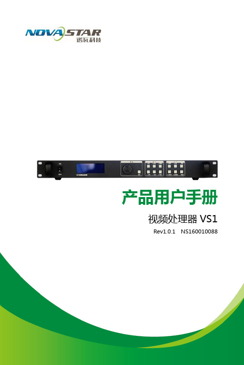
诺瓦科技LED视频处理器VS1用户手册
输出设置 双画面
分辨率、水平宽度、垂直高度、水 平起始、垂直起始、显示(局部/ 全屏)、自定义分辨率
双画面(开/关)、CH2 信号(信号 源选择)、图层、透明度、水平宽度、 垂直高度、水平起始、垂直起始、 图文叠加
图文叠加(开/关)、 预设模式、透明度
图像截取
CH1 截取 CH2 截取
图像截取(开/关)、水平宽度、垂直高度、
有
技
控制Βιβλιοθήκη UART IN、OUT CTRL
科 处理器同步调用通信接口 子USB 上位机控制接口
输入
AV1、AV2
电 VGA 瓦 DVI
视频输入接口,BNC 接口,同轴信号线 VGA 输入接口 DVI 输入接口
诺HDMI EXT
HDMI 输入接口 SDI 扩展输入接口(选配)
输出
安发送卡 西电源
DVI-1、DVI-2 发送卡 电源
司
第二行:通道 2、信号源、输入源信号格式; 第三行:输出、输出信号分辨率及刷新率; 第四行:状态栏,各图标含义如下:
限公
双画面功能关闭;
有
双画面开,通道 1 画面置于顶层;
技
双画面开,通道 2 画面置于顶层;
科 部分显示功能开启,输出图像尺寸为窗口大小; 子 全屏显示功能开启,输入图像全部都显示到输出窗口; 电 通道 1 图像截取关,输出为完整图像;
技 1536×1536@60Hz、1600×1200@60Hz、
1680×1050@60Hz、1920×1080@60Hz、
科 1920×1200@60Hz、2048×640@60Hz、
子2048×1152@60Hz 、2304×1152@60Hz、 2560×816@60Hz、1920×1080@50Hz、
诺瓦科技LED视频处理器Thunderview_V1规格书

Thunderview_V1视频处理器版本编号: V1.0.0 文档编号:NS160010171规格书西安诺瓦电子科技有限公司版权所有 ©2017 西安诺瓦电子科技有限公司。
保留一切权利。
非经本公司书面许可,任何单位和个人不得擅自摘抄、复制本文档内容的部分或全部,并不得以任何形式传播。
商标声明是诺瓦科技的注册商标。
声明欢迎您选用西安诺瓦电子科技有限公司(以下简称诺瓦科技)的产品,如果本文档为您了解和使用产品带来帮助和便利,我们深感欣慰。
我们在编写文档时力求精确可靠,随时可能对内容进行修改或变更,恕不另行通知。
如果您在使用中遇到任何问题,或者有好的建议,请按照文档提供的联系方式联系我们。
对您在使用中遇到的问题,我们会尽力给予支持,对您提出的建议,我们衷心感谢并会尽快评估采纳。
网址:http://www.novastar.tech西安诺瓦电子科技有限公司规格书目录目录1 概述 (1)2 功能特性 (2)3 硬件介绍 (3)4 尺寸 (5)5 规格参数 (6)西安诺瓦电子科技有限公司规格书 1 概述1 概述Thunderview_V1是一款由诺瓦科技研发的视频处理器,其基于一个强大的FPGA处理平台,支持包括2路SDI,1路DP,1路CVBS,1路VGA,3路HDMI,1路DVI及1路HDBT等多样化的信号输入,输入分辨率最高支持4096x2160@60Hz,超高清画面的输入输出,延迟时间短并且信号源切换速度仅为0.25s,可以为您带来更加极速的操作体验。
西安诺瓦电子科技有限公司规格书 2 功能特性2 功能特性●Thunderview_V1具有完备的视频输入接口,包括2路SDI,1路DP,1路CVBS,1路VGA,2路HDMI2.0,1路HDMI1.3,1路DVI,1路HDBT;●支持的输入分辨率最高可达4096x2160@60Hz;●Thunderview_V1可根据显示屏分辨率对输入图像进行缩放;●画中画的位置、大小等均可调节,可以随心所欲的控制;●1路S/PDIF,外置独立音频输出;●支持多台拼接带载;●Thunderview_V1无须通过计算机软件进行系统配置。
诺瓦科技LED视频控制器V900用户手册
1
EIA/CEA-861 标准,符合 HDMI-1.3 标准,支持 HDCP
1
最高支持 1080p@60Hz 输入
-3-
V900 用户手册
电气参数
处理器接口及性能指标见下表:
输入接口 接口 CVBS VGA DVI HDMI YPbPr SDI 整机规范 输入电源 整机功耗 工作温度 外形尺寸 重量
数目 分辨率/规格
2
PAL/NTSC
2
VESA 标准,最高支持 1080p@60Hz 输入
1
VESA 标准 (支持 1080i 输入),支持 HDCP
接地:本产品通过电源的地线与大地相连,请确保接地导体的良好接地。
电磁干扰:设备应远离磁铁、马达及变压器。 防潮:请将设备置于干燥、干净的环境中。如有液体浸入,请立即拔掉电 源插头。 远离易燃易爆危险物品。
禁止液体、金属碎片浸入机器内部,以免引起安全事故。
附件
V900 用户手册
电源线一条
DVI 线一条
统配置,所有操作几步即可完成,这就是我们所倡导的“司机点屏”!
V900 是 Nova 新一代控制器的系列产品,强大的图像处理、专业的图像控制、以及 友好的人机界面,使显示屏控制工作从未如此轻松和愉快。
-1-
目录
V900 用户手册
第一章 功能简介 .............................................................................. 2
输入输出接口示意图.......................................................................................... 2 前面板控制显示示意图 ...................................................................................... 3 操作说明 ........................................................................................................... 3 电气参数 ........................................................................................................... 4
诺瓦科技LED视频处理器LED视频拼接器VS7使用手册
文档为您了解和使用产品带来帮助和便利,我们深感欣慰。我们在编写文档时力求 精确可靠,随时可能对内容进行修改或变更,恕不另行通知。如果您在使用中遇到 任何问题,或者有好的建议,请按照文档提供的联系方式联系我们。对您在使用中 遇到的问题,我们会尽力给予支持,对您提出的建议,我们衷心感谢并会尽快评估 采纳。
VS7 支持配置 16 种用户场景,场景数据配置好后,用户后续可以直接通过场 景名称调用配置好的用户场景。
• 旋转旋钮至要加载的场景,按下按钮即可加载该场景。 • 进入“场景载入”后,前面板中数字按键灯亮,可通过数字按键快速加载
相应的场景。若场景序号为两位数时,在两秒钟内快速按下场景序号的 数字即可,如“场景 15”,在两秒内分别快速按下数字“1”和“5” 即 可加载“场景 15”。
1.1 系统架构
ંை ࢛࢛ҵ
<9
ݏӲ
֘ުॐى
1.2 软件安装
V-Can 的安装方式与普通软件相同,根据安装向导提示操作即可。 如果在遇到杀毒软件或防火墙弹出提示的时候,请选择允 许,因为安装程序安装过程可能需要安装串口驱动程序。
2 外观说明
2.1 前面板
① 电源开关
ON/ OFF。 1
输入 -A
接地:本产品通过电源的地线与大地相连,请确保接地导体的良 好接地。
电磁干扰:设备应远离磁铁、马达及变压器。
防潮:请将设备置于干燥、干净的环境中。如有液体浸入,请立 即拔掉电源插头。
远离易燃易爆危险物品。
禁止液体、金属碎片浸入机器内部,以免引起安全事故。
目录
1 概述 .................................................................................................................1
诺瓦科技Micro LED视频拼接软件V-Can使用手册教程英文版

2.2 Installation ................................................................................................................................................ 2
No part of this document may be copied, reproduced, extracted or transmitted in any form or by any means without the prior written consent of Xi’an NovaStar Tech Co., Ltd.
http://www.novastar.tech
12 3.2.1.3 Hot Backup .......................................................................................................................
18 3.2.6 Setting Layer Properties ...............................................................................................................
诺瓦科技LED显示屏视频处理器VX4-VX4S用户手册
User's ManualLED Video Controller VX4S/VX4 StatementYou are welcome to use the products from Xi’an NovaStar Tech Co., Ltd. (hereinafter referred to as Novastar). It is our great pleasure to offer this manual to help you understand and use the product. We strive for precision and reliability during the compilation of this manual, and the contents of this manual are subject to change without notice. If you have any problem in use or you have any suggestion, please feel free to contact us according to the contact information provided in this manual. We will do our utmost to satisfy your needs. Also, we would like to express our sincere thanks to your suggestions and make assessment as soon as possible for adoption.CopyrightNo part of this manual may be reproduced or transmitted in any form or by any means without prior written consent of Xi’an NovaStar Tech Co., Ltd.Trademarkis a registered trademark of NovaStar Tech Co., Ltd.Rev1.1.1 NS160110080Safety StatementTo avoid potential hazards, please use this equipment according to the regulations. In case of damages, non-professionals should not disassemble it for maintenance without permission. Please contact the after-sales department of the company.High voltage danger: The operating voltage of this product is 100-240V AC.Grounding: This production is connected to ground via the ground wire ofpower supply. Please ensure good grounding of grounding conductor.Electromagnetic interference: The device should be kept far away frommagnets, motors and transformers.Moisture proof: Keep the equipment in a dry and clean environment. In caseof liquid immersion, please pull the plug immediately.Keep away from flammable and explosive dangerous goods.Prevent liquids or metal fragments from being immersed into the machineto avoid safety accidents.Contents1 Model description 12 Appearance1Front Panel (1)Rear Panel (2)3 Signal connection 34 Dimension 35 Operating motion instruction 36 Main Interface 47 Operation instruction 5Step1: Input Settings (5)Step2: Screen Settings (5)Setp3: Brightness (7)Setp4: Output Settings (7)Image Mosaic (8)Advanced Settings (9)Factory Reset (15)Communication Settings (15)Language (15)8 Specifications169 FAQ 171 Model descriptionModel Description (input interface type)VX4 DVI×2, VGA×3, CVBS×3, HDMI×1, DP×1VX4S DVI×1, VGA×2, CVBS×2, HDMI×1, DP×1, SDI×1Tips: VX4 has different type and number of interface with VX4S, but their functions and specifications are basically the same. In this manual, VX4 is described as the example.2 AppearanceFront Panel③ :Knob T o press knob means Enter or OK, rotating knob represents selection or adjustment.⑤: Four control keyboard shortcutsPIP: PIP Turn-on/off. The lighting of this key represents the turn-on of PIP; otherwise, PIP is turned off.SCALE: Picture zoom turn-on/turn-off. The lighting of this key represents the turnon of zoom function; otherwise, zoom function is unavailable.MODE: Shortcut menu of loading or storage of display model. The key is light when entering the model or shortcut menu, in case of exiting, the key is not bright.TEST: Shortcut of turn-on/off of testing picture. In case of entering testing picture, the key is bright; otherwise, the key is not bright.⑥:Shortcut keys for switching of 10 signal input source. Short press to set as the mainscreen input source, and long press to set as PIP input source. The key is bright after press when the video source has signal; the key flashes when the input of ④: ESC Escape current operation or selection.video source has no signal. The setting result can be checked while setting on the display screen and OLED screen.⑦: Function keysTAKE: Display switching shortcut key. After short pressing TAKE key, PIP will be opened; if it has been opened, the switching between MAIN and PIP will be realized. Fn: Custom shortcut key.⑧: Flat mouth (Type A, female USB) is USB interface, which connects U disk;Square mouth (Type B female USB) is USB controlling interface, communication with PC.Rear PanelInput SourceAudio Audio InputDP DP InputHDMI HDMI InputCVBS1~CVBS3 3-Channel PAL/NTSC TV composite video InputsDVI -1~DVI-2 2-Channel DVI InputsVGA1~VGA3 3-Channel VGA InputsOutput InterfaceDVI LOOP DVI LOOP OutputMonitor -VGA OUT VGA Monitoring InterfaceMonitor -DVI OUT DVI Monitoring InterfaceLED Out 1、2、3、4 4-Channel LED OutputsControlling InterfaceETHERNET Network Control (Communication with PC, or Access Network)Type B, female USB USB Control (Communication with PC, or Cascade IN) Type A, female USB USB Cascade OUTPowerAC 100-240V ~ 50/60HZ AC Power InterfaceTips:The two USB interfaces ( typeA) on front panel and rear panel are both forbidden to connect with PC directly.3 Signal connectionConnect the required hardware equipment reference with the interface descriptions of the previous chapters.If it is required to control more than one set of VX4, please connect them according to the following figure.4 DimensionVX4 's dimension (Unit:mm)5 Operating motion instructionKnob:③ Press the knob under the main interface to enter the operation interface menu; ③ Rotate the knob to select menu or press the knob under the operation interface ofmenu to select current menu or enter submenu;③ Rotate the knob to adjust the parameter after selecting the menu with parameter;press the knob again for confirmation after adjustment. ESC: Return key, exit current menu or operation.Key lock/unlock: long press knob and ESC key simultaneously.6 Main InterfaceAfter starting the controller, the main interface of OLED display is as follows:NovaStar1921680101024x768@60Hz 1024x768@60Hz1 VGA12 HDMI1 2 3 425%First row: Company name; the name and IP of the product are shown alternately; Second row: Main screen 1; signal source; input source signal format; Third row: PIP 2; signal source; input source signal format; Forth row: Status bar. the meanings of all icons are shown below.LED Output (it is output Port 2 in primary mode currently, andthe backup status is displayed as )PIP is turned offPIP is turned onThe current effect is point-to-point displayIt is “scale down” modeIt is “scale up” modeImage Mosaic is not enabled;Image Mosaic is enabled;It is USB control currentlyIt is network port control currentlyThe current brightness is 25%Sign of press key lock. When this icon appears at the maininterface, it is in locking state for key and knob functions.7 Operation instructionThe functions of VX4 are powerful with very simple operation, and multiple operations can be completed with a knob and a return key. The design of more than one shortcut keys makes operations more efficient.Generally, the LED display can be used normally, and the brightness is moderate after conducting the following four steps:Input settings → Screen settings → Brightness → Output settings. Other menus such as screen control and senior setting can help users better control LED display.See the following section for details of operations.Step1: Input SettingsSet resolution of input source signal. Resolution can be directly set and changed for digital input interfaces DVI, HDMI and DP . Resolution can only be modified with other input methods on input devices.Input resolution can be set in two methods:Method one: Preset Resolution.Selection is made in preset resolution of the controller. If there is no preset resolution, you can select the second method and customize resolution.Brightness25%Screen Settings Input Settings Output SettingsPreset ResolutionCustom ResolutionSet Horizontal Res, Vertical Res and Custom· refresh rate and then select "Apply" and press the knob for application. If the application is not confirmed, custom resolution is Preset ResolutionCustom ResolutionWidth (H) 1920 Height(V) 1080Custom Refresh RateApplyStep2: Screen SettingsThe precondition of Screen setting in shortcut is that the screen must be regular rectangle (not special-shaped), cabinet must be regular rectangle and the size of each cabinet are identical.Step 1 The screen being power-on, if the cabinet is in normal display, enter into Step2; if the cabinet is in abnormal display, first, load the cabinet file, and save it to the receiving card; see detailed operation in Advanced Settings ;Step 2 Return to the “Screen Settings” submenu. Rotate the button to switch tosubmenus of other options respectively to perform configurations, as shown in the following figures:Cabinet Row Qty Cabinet Column Qty Port 1 Cabinet Qty Data Flow (Front View )Step 3 Set Cabinet Row Qty and Cabinet Column Qty according to the actual situationof the screen;Step 4 Set Port1 Cabinet Qty. The device has some limitations on the cabinet quantityof ports. For details, see precautions for screen settings;Step 5 Set the Data Flow (Front View). Pay attention to precautions for screen settingsc), d) and e) below.Precautions for screen settings:1024x768 1280x1024 1366x768 1440x90060 H z 59.94 H z 50 H z 30 H zBrightness25 %Input Settings Screen Settings Output Settings3 3 4(a)If the number of ports with loads is n (n≤4), the first n-1 ports must load the same number of cabinets, which must also be an integral multiple of the number of cabinet rows or columns and be greater than or equal to the number of cabinets for the nth ports.Example:For example, if port 1, port 2, port 3 have loads, port 1 and port 2 must have the same number of cabinets, which must also be an integral multiple of the number of cabinet rows or columns. Therefore, you only need to set port 1 cabinet Qty according to the actual situation when setting the screen. The number of receiving cards port 3 loads must be smaller than or equal to port 1.(b)In the case of special-shaped cabinets, different cabinet sizes and specialshaped screen, the NovaLCT-Mars software is required to be connected to configure the screen.(c)During Data Flow setting, you can rotate the button to see the effects of different data flow on the screen in real time. If you are satisfied with the effect of current data flow, you must press the button to save the setting. You can press the ESC to exit from the current operation.(d)During Data Flow setting, you must ensure that the data flow of each port is downward in the same direction.(e)During Data Flow setting, you must ensure that Port 1 is the start position of the whole data flow connection.VX4 can load 2.3 million (2048x1152@60Hz) pixels in maximum. The width of lateral load can reach to 3840 pixels in maximum (3840x600@60Hz); the longitudinal load can reach to 1920 pixels in maximum (1920 x1200@60Hz).Setp3: BrightnessReturn to the main menu interface. Press the Knob to select the corresponding value of Brightness. You can rotate the Knob to adjust the value at this time.BrightnessScreen SettingsInput Settings Output Settings 25%BrightnessScreen SettingsInput SettingsOutput Settings25%Setp4: Output SettingsOutput settings are divided into three cases:First one: disable Scaling, i.e., the sizes of output image and input image are the same, and original scale output is used. If the input resolution is smaller than the LED display in one direction, LED display may not become bright in this direction; if the input resolution is greater than the LED display in one direction, the input contents may not be displayed completely in this direction. This option is applicable to the application scenarios requiring point-to-point display. Horizontal offset and vertical offset of images can be set according to the needs, and at this time the displayed contents may move to the left or top at the LED display.At this point [Scaling] is disabled.Second one: Auto Fit At this point [Scaling] is enabled, and [Auto Fit] is enabled. When enabling [Auto Fit], the input contents will be fully zoomed to the size of LED display, and the input contents will be adaptive to the size of LED display. This mode is suitable for full-screen playback of the contents.Third one: Custom Scaling At this point [Scaling] is enabled, while [Auto Fit] is disabled. The following steps should be performed for custom scaling:Step 1 Set the input Capture, i.e., capture part of the interesting screens from one starting point of inputting image and display it on LED display. It is generallyrequired to set Horizontal Res (smaller than or equal to the lateral resolutionof input source), Vertical Res (smaller than or equal to the vertical resolutionof input source), horizontal X and vertical Y.Step 2 Set output window, the size of window is smaller than or equal to the size ofLED display; after setting the window, the images can only be adaptive to the displayed size within the range of window. This option is applicable to the application scenarios requiring reserving border at the LED display or restricting playing area.After setting according to the above two steps, the captured contents will only be input and displayed at the set area on the LED display, as shown below:Image MosaicWhen the display screen is huge, two or more VX4 need to be cascaded for loading the huge screen;Choose the method of Image Mosaic: Equal Division, Unequal Division.③ Equal Division: Each VX4 has same load area. It is only required to set total pixelpoints, rows ,columns of the big screen and the serial No. of each VX4.③ Unequal Division: Each VX4 could have different load area . It is required to set thetotal pixel points and the load area size as well as load area staring position of each VX4.Image Mosaic example: The total number of pixels of LED display is 3000×1000, exceedingthe load capacity of single VX4. Two sets of VX4 are used for Image Mosaic processing. The connection method is shown in the right figure.Scaling Auto FitCustom Scaling Image OffsetEnable DisableInput Source Width(H) Height(V) Start X HDMI 720 Input Capture Output Window240 Start YHeight (V) Start X Start Y600 100 Input Capture Output WindowWidth (H) 800 100Input SourceLED Display(100,100)800600(0 ,0) 720240Please choose Equal Division or Unequal Division while setting detailed parameters. Equal DivisionVX4(1) VX4(2)Total Width Pixels 3000 Total Height Pixels 1000 Mosaic Row Qty 1 Mosaic Column Qty 2Load Area Position1 2 ——————Unequal DivisionAdvanced SettingsSeveral setting options of main functions are included in advanced settings, as shown in the figure below. Operation of each function will be detailed for users in the following text.VX4 ( 1 ) VX4 ( 2 )Total Width Pixels 3000 Total Height Pixels 1000Load Area Width 1500 1500 Load Area Height 1000 1000 Load Area Start X 0 1500 Load Area Start YControl the turn-on/off of PIP, Set input source of main screen and PIP, as well as parameters of PIP.Layout: the position of PIP relative to main screen, including eight modes of layout such as Custom, Left T op, Left Bottom, Right Top etc. When choosing any mode except Custom , the values of horizontal and vertical offset of PIP are able to adjust to the corresponding values of layout automatically. The meaning of each layout mode is shown below:③Custom refers to that the size and position of PIP need to be set.③Left Top, Left Bottom, Right T op, Right Bottom, Center refer to that PIP overlapswith the top-left corner, bottom-left corner, top-right corner, bottom- right corner and center of main screen.③Top Bottom, Left Right refer to that main screen and PIP are distributed from topto bottom or left to right.Main source/PIP source: Input source switching of main picture and PIP is the same as the role of input source switching on the front panel.Horizontal Res : Horizontal offset of PIPVertical Res : Vertical offset of PIPHorizontal X : Horizontal width of PIPVertical Y : Vertical height of PIPPIP Crop Settings: Picture is cropped from the set starting position and is displayed on PIP and its size is set horizontal width and vertical height.Enable this function and then set horizontal width, vertical height, horizontal X and vertical Y.Transparency: the transparency of PIPWindow Swap: s content of main screen and PIP.The Conflict List of PIP Signal Source(VX4)Input Source of Main ChannelHDMI DVI1DVI2VGA1VGA2VGA3CVBS1CVBS2CVBS3DPPIP Input Source HDMI√×√√√√√√√DVI1√√×√√×√√√DVI2×√√√√√√√√VGA1√×√√√×√√√VGA2√√√√×√√√√VAG3√√√√×√√√√CVBS1√×√×√√√√√CVBS2√√√√√√√×√CVBS3√√√√√√√×√DP√√√√√√√√√HDMIInput Source of Main ChannelHDMIDVIVGA1VGA2CVBS1CVBS2SDIDP PIP Input SourceHDMI ×√√√√√√DVI×√√√√√√ VGA1 √ √× √√√√ VGA2 √ √ ×√√√√ CVBS1 √ √ √ √× √√ CVBS2 √ √ √ √ ×√√SDI√ √ √ √ √ √√ DP√√√√√√√Redundancy Set this controller as primary or backup mode.VGA Auto ADJ ADC Calibration Video Synchronization EnableGo Homepage (s )60③ so that the VGA picture is clear and complete. Select this menu and then press the knob once and perform VGA automatic adjustment once. (VGA1 does not support this feature)③ ADC calibration: when analog signal accesses, processors that are not calibrated byADC may have defects such as color cast or picture dark. VX4 can automatically make ADC calibration based on input analog signal (including CVBS and VGA) to solve the problems above. Select this menu and then press the knob once and perform ADC calibration once.③ Video Synchronization: allow that the input and output of VX4 are synchronous. ③ Go Homepage(s): The time period during which the system stops at currentinterface and then automatically returns to home screen when there is no operation. The system default value is 60s.PIPRedundancy PresettingsAdvanced AttrPresettingsSave the current configuration parameters as Presettings. The Presettings can be directly loaded next time, and 10 Presettings are saved by default.Custom ButtonFn Settings. The functions of custom button include Black Out, Freeze 、VGA Auto ADJ 、Video Synchronization. Press Fn key to directly conduct the function switch.Audio SettingsControl the enabling /disenabling of Audio, volume and Audio mode.For example, when using the audios input via Audio In port, it is required to enable audios first and then select the Audio mode to be fixed; when using the Audio from HDMI, set the Audio mode to be accompanied after enabling audios and then switch source to HDMI, and the Audio we hear comes from HDMI.Display Control③ Normal: Normally display. Blank Out: The display is blank ③ Freeze: The currentplay lists are frozen.③ Testing Pattern: There are eight kinds of testing screens in total, including pure color and lines.③ Image SettingsContrast, Saturation, Hue, Color Temperature, Red, Green, Blue and Gamma value are set according to the requirements. After they are adjusted to satisfaction, the parameters should be saved.③ Switching Effect:Set the effects when switching screens, including Quick switch,Fade, Shrink Center, Shrink Left Top, Zoom Center, Zoom Left T op and turning off. After selecting the desired effect, it will take effect after pressing the knob.Fn Settings Audio Settings Display Control Inputs BackupAudio Volume Audio ModeEnable 100Normal Black out Freeze Test Pattern Fn Settings Audio Settings Display Control Inputs BackupImage Settings Switching EffectTips: When enabling PIP function, the switching effect will automatically disappear. Only when PIP function is turned off, the special effect function of channel switching can take effect.Inputs BackupTo specify backup for input source and automatically switch to backup source if the signal of input source has faults, which makes it more reliable.HDMI DPIndicating that DP has been set as the backup of HDMI and main inputsource(which cannot be changed) is in left side of the arrow while backup(which can be changed) is in the right side;Both main input source and backup can be customized in Custom mode.Output ResolutionThis function can be used to set the the output resolution of monitoring. Users can set the function according to actual use and choose either Reset Resolution or Custom.Output Resolution Cabinet Settings OLED Brightness 13Hardware VersionV1300Cabinet SettingsLoad Cabinet FilesVX4 is connected with PC. NovaLCT-Mars runs on PC and the cabinet setting previously is imported into controller. 1 ) Save cabinet configuration file.After receiving card is configured, click and save cabinetconfiguration file (.rcfg) to local PC.Preset Resolution Custom ResolutionFn Settings Audio Settings Display Control Inputs BackupBackup Backup 1 Backup 2 Backup 3Enable HDMI VGA1 CVBS1DP SDI VGA2 Custom Backup CVBS2SDILoad RCFG Files Save to RV CardOLED Brightness 13 Hardware VersionV1300Output Resolution Cabinet Settings2 ) Cabinet configuration imported into VX4.Save to RV CardAll current configurations about the recieving card of VX4 are saved into receiving card and will not be lost after power fault.OLED BrightnessAdjust the gray scale of OLED display.3 ) Load Cabinet Files.RG 128×128Load RCFG FilesSave to RV CardHardware VersionView the hardware version of VX4. If new version has been published, LCT-Mars can be connected via PC and the hardware program of VX4 can be upgradedFactory ResetReset to factory default setting.Communication SettingsSet the communication mode and network parameter of VX4.The communication modes include USB priority and LAN (local area network) priority. When VX4 is connected to USB control and LAN control interface simultaneously, USB takes priority in the settings, adopts USB control; otherwise, LAN takes priority in the settings, adopts LAN control.The network parameter can be set both manually and automatically. Ensure that the IP address is not conflict with other equipment when setting parameter manually.LanguageSwitch Language.8 SpecificationsInputNumberPort Resolution SpecificationVX4VX4SVGA 3 2 VESA Standard, support max 1920×1200@60Hz input DVI 2 1 VESA Standard (support 1080i input), support HDCP CVBS 3 2 PAL/NTSCHDMI 1 1EIA/CEA-861 standard, in accordance with HDMI-1.3 standard, support HDCPDP 1 1 VESA StandardSDI 0 1 480i、576i、720P、1080i/P OutputSDI LOOP 0 1 Consistent with DVI input1280×1024@60Hz 1440×900@60Hz 1680×1050@60Hz 1600×1200@60Hz 1600×1200@60Hz – ReducedVGA 1 1 1920×1080@60Hz 2560×816@60Hz2048×640@60Hz 1920×1200@60Hz2304×1152@60Hz 2048×1152@60Hz1024×1280@60Hz 1536×1536@60HzSelf-defined output resolution (Bandwidth DVI 1 1 optimization)Horizontal resolution maximum 3840 pixelsVertical resolution maximum 1920 pixelsConsistent with SDI inputSpecification of complete machineInput Power AC 100-240V, 50/60HzOverall Power Consumption 25WOperating Temperature -20~60℃Size 482.6×251.5×45(mm)Weight 2.55 Kg9 FAQQuestions MethodsLED display is off Inspect whether the power connection is correct and the switch has been turned on;Play the Self test image and confirm whether the connection of LED is correct and works normally;Inspect whether VX4 output has signal and shows blank screen; Inspect whether the mode and parameter of screen configuration are correct;Port Resolution SpecificationVX4VX4SDVI LOOP 1 1Monitoring port output is abnormal Check whether there is image input in input channel and whetherit is correctly displayed;Check whether PIP has been turned on, whether there is signalinput in 2 channel and whether it is correctly displayed;Check whether monitoring output is connected correctly and it is not loose;Please confirm whether Monitor supports the output resolution ofVX4;Try to cut off the power of equipment and restart it, reset VX4 andoperate again;P h a s e o f V G Ainput offsetPerform VGA Auto ADJ; P I P d i s p l a y i sabnormalCheck whether there is signal input in 2 channel and it is normally displayed; Check PIP and confirm whether parameter setting is normal; Fading is abnormalCheck whether Switching effect has been enabled; Image Mosaic isabnormal Check whether the VX4 Image Mosaic switch has been turned on and whether Image Mosaic parameters settings is correct; Checkwhether input signal source is normal;Sound is abnormal Check whether the volume settings is appropriate;Check whether the Audio mode setting is correct;Confirm VX4 is well connected to multifunction card, and thecorresponding output port icon on the main interface has beenhighlighted; confirm whether the audio output mode ofmultifunction card is HDMI mode (it is required to connect LCT forconfirmation and setting);Please preliminarily investigate problems according to the above steps; if you cannot eliminate the problems, please contact the local dealer or our company’s customer service personnel.There is high voltage inside the machine. In order to guarantee your safety, please do not maintain the processor by yourself.。
诺瓦科技LED视频控制器VX6s用户手册
3.3.2 输入画质调整 ........................................................................................................................................... 8
电磁干扰:设备应远离磁铁、马达及变压器。
防潮:请将设备置于干燥、干净的环境中。如有液体浸入,请立即拔掉 电源插头。
远离易燃易爆危险物品。
禁止液体、金属碎片浸入机器内部,以免引起安全事故。
www.noHale Waihona Puke
ii
二合一视频控制器 VX6s 用户手册
更新记录
发布版本 V1.0.0
发布时间 2018.07.24
修订说明 首次发布
前言
西安诺瓦电子科技有限公司
iii
二合一视频控制器 VX6s 用户手册
目录
目录
前 言................................................................................................................................................. ii
1 概述..................................................................................................................................................1
诺瓦科技LED视频处理器Thunderview_V1用户手册英文版
Thunderview_V1Video ProcessorDocument Version V1.0.0 Document Number: NS160110174User ManualXI 'AN NOVAS T AR T E C HCO .,L T D.Copyright © 2017 Xi’an NovaStar Tech Co., Ltd. All Rights Reserved.No part of this document may be copied, reproduced, extracted or transmitted in any form or by any means without the prior written consent of Xi’an NovaStar Tech Co., Ltd.Trademarkis a registered trademark of Xi’an NovaStar Tech Co., Ltd.StatementYou are welcome to use the product of Xi’an NovaStar Tech Co., Ltd. (hereinafter referred to as NovaStar). This document is intended to help you understand and use the product. For accuracy and reliability, NovaStar may make improvements and/or changes to this document at any time and without notice. Any problem in use or any good suggestion, please contact us through ways provided in the document. We will do our utmost to solve the problems and adopt the suggestions after evaluation as soon as possible. Website: http:// www.novastar.techXI 'AN NOVAS T AR T E C HCO .,L T D.User ManualContentsContents1 Overview ......................................................................................................................................... 1 2 Hardware . (2)2.1 Front Panel .................................................................................................................................................. 2 2.2 Rear Panel (3)3 Applications ................................................................................................................................... 4 4 Operations .. (5)4.1 Home Screen ............................................................................................................................................... 5 4.2 Main Menu ................................................................................................................................................... 6 4.3 Brightness .................................................................................................................................................... 6 4.4 Input Settings .. (6)4.5 Output Settings ............................................................................................................................................ 7 4.6 Scaling (8)4.7 PIP (9)4.8 Splicing ........................................................................................................................................................ 9 4.9 Image Quality ............................................................................................................................................. 10 4.10 Advanced Settings (11)4.11 Factory Reset ........................................................................................................................................... 12 5 Web Control ................................................................................................................................. 14 XI 'A N N O V A S T A R T E C HCO .,L T D.User Manual 1 Overview1 OverviewThe Thunderview_V1 is a video processor developed by NovaStar based on thepowerful FPGA processing platform. It is designed with various signal inputs, including 2SDI, 1 DP, 1 CVBS, 1 VGA, 3 HDMI, 1 DVI and 1 HDBT. It supports input resolutions upto 4096x2160@60Hz and UHD input and output displays. With low latency and a fastsignal source switching within 0.25 second, it can give you a faster operationexperience.X I'A NN OV AS TA RT EC HC O.,L TD.2Hardware2.1 Front PanelFigure 2-1 Front panel① Power button ② LCD panel③ Press the knob to display the main menu or confirm an option or operation. ④ Shortcut keys of input source selection: Corresponds to the input source ports on the rear panel. ⑤ To load the .png file; after the Thunderview_V1 is connected to the upper computerthrough the Ethernet cable, it is required to visit 192.168.0.111 to configure the IP. ⑥ To display the PIP menu screen ⑦ Custom button: Users can set it to be the blackout, freeze or test function.⑧ To display the scaling menu screen ⑨ USB: For MCU upgradeX I 'A NN O V AS T AR T E C HCO .,L T D.2.2 Rear PanelFigure 2-2 Rear panel3 Applications Figure 3-1 ApplicationX I'A NN OV AS TA RT EC HC O.,L TD.4OperationsOperation instructions Knob:1. On the home screen, press the knob to enter the main menu.2. On the main menu, rotate the knob to select a menu item. Then, press the knobto confirm the current selected item or to enter the submenu. 3. When a menu item with parameters is selected, you can rotate the knob toadjust the parameters. Please note that after adjustment, you need to press the knob again to confirm the adjustment. BACK button: A return key, used to exit the current menu or operation4.1 Home ScreenAfter the Thunderview_V1 is turned on, the home screen is shown as below.● INPUT : Input source resolution ● OUTPUT : Output source resolution ● HDMI3: Currently used input source ●PIP− : PIP enabled − : PIP disabled●Scaling− : Scaling function enabled −: Scaling function disabledXI 'AN NOVAS T AR T E C HCO .,L T D.●Splicing− : Splicing mode enabled −: Splicing mode disabled●Genlock− : Genlock enabled −: Genlock disabled●Brightness−: Current output display brightness4.2 Main MenuOn the home screen, press the knob to enter the main menu. On the main menu, rotate the knob to select a menu item. Then, press the knob to confirm the current selected item or to enter the submenu, or press the BACK button to go back to the previous screen.Functions on the main menu: Brightness , Input Settings , Output Settings , Scaling , PIP , Splicing , Image Quality , Advanced Settings , and Factory Reset Figure 4-1 Main menu4.3 BrightnessSet the output display brightness which ranges from 0 to 100 and defaults to 50.4.4 Input SettingsInput settings include selecting an input source and setting the EDID of the inputsource.XI 'AN NOVAS T AR T E C HCO .,L T D.Figure 4-2 Input settings● Input Source : 3G-SDI1, 3G-SDI2, DP , HDMI1, HDMI2, DVI, VGA, CVBS, HDMI3, LOGO, HDBT, TESTPAT●Preset Resolution : 640x480p, 720x480i, 720x480p, 720x576i, 720x576p, 800x600p, 1024x768p, 1080x1920p, 1280x720p, 1280x768p, 1280x800p, 1280x1024p, 1360x768p, 1366x768p, 1400x1050p, 1440x900p, 1600x1200p, 1680x1050p, 1920x1080i, 1920x1080p, 1920x1200p, 2048x1080p, 2048x1200p, 2560x1080p, 2560x1440p, 2560x1600p, 3840x2160p, 4096x2160p●Preset Rate : 60Hz, 59.94Hz, 50Hz, 48Hz, 30Hz, 29.97Hz, 25Hz, 24Hz, 23.98HzNote:The logo cannot be loaded through the Thunderview_V1. To load it, perform the following steps.1. Connect the Thunderview_V1 to a PC properly by using an Ethernet cable.2. Ensure that the IP addresses of the PC and the Thunderview_V1 are in the same network segment.3. Type the IP address of the Thunderview_V1 (http://192.168.0.111) in thebrowser’s address box and enter the web control page. 4. Click LOGO in the Inputs menu and then click Backup/Restore .5. Click Select file in the Restore settings from files bar. After selection, click Restore . 4.5 Output Settings Output settings include setting the resolution and refresh rate of the output source,the aspect ratio and the synchronization mode of the output display. Figure 4-3 Output settings●Output Resolution : 720x576p, 800x600p, 1024x768p, 1080x1920p,1280x720p, 1280x768p, 1280x800p, 1280x1024p, 1360x768p, 1366x768p,1400x1050p, 1440x900p, 1600x1200p, 1680x1050p, 1920x1080i, 1920x1080p,XI 'A N N O V A S T A R T E C H CO .,L T D.1920x1200p, 2048x1080p, 2048x1200p, 2560x1080p, 2560x1440p, 2560x1600p, 3840x2160p, 4096x2160p● Output Rate : 60Hz, 59.94Hz, 50Hz, 48Hz, 30Hz, 29.97Hz, 25Hz, 24Hz, 23.98Hz●Aspect Ratio : Original, Full Screen, Crop, Anamorphic−Original : The input image is scaled to completely fit the display area either horizontally or vertically without any distortion. The input aspect ratio is preserved and unused areas on the top/bottom or left/right are set black. −Full Screen : The input image is scaled to completely fit the display area without preserving the aspect ratio of the source. This will cause distortion but no black areas will be visible.−Crop : The input image is scaled to completely fit the display area whilepreserving the aspect ratio of the source. Portions of the input image on the top/bottom or left/right will be cropped out of the output image.− Anamorphic : The image will be treated as in crop, but it is always scaled to a 16:9 aspect ratio.●IO Lock : Lock the output displays to be synchronous− Off : Disable the synchronous mode.− Source : Use an input source as the synchronization signal.−Genlock : Use an external Genlock source as the synchronization signal. 4.6 Scaling Set the scaling of output display, including the dimensions and position of the scaled display.Figure 4-4 Scaling● Scaling : Enable or disable the scaling function.● Scale Value : Unit of scaling, which is pixel or percentage ● Aspect Lock : Enable or disable the aspect lock function ● Zoom H : Horizontal width of the scaled display ● Zoom V : Vertical height of the scaled display ● H Offset : Horizontal position offset ● V Offset : Vertical position offset●Scale Reset : Reset the parameters of scaling.XI 'A N N O V A S T A R T E C H C O .,L T D.4.7 PIPSet the input source, dimensions and position of PIP . Figure 4-5 PIP● PIP : Enable or disable the PIP function. ●Layout : Choose the position of the PIP .− R+B : PIP at the bottom right of the main window− R+T : PIP at the top right of the main window−L+B : PIP at the bottom left of the main window− L+T : PIP at the top left of the main window −Custom : Customize the position of the PIP in the main window by adjusting the Start X and Start Y parameters to move the position. ● Main Source : Choose the input source of the main window. ● PIP Source : Choose the input source of the PIP . ● Width(W): Horizontal width of the PIP ● Height(H): Vertical height of the PIP● Start X : Starting position of the PIP at the horizontal direction ●Start Y : Starting position of the PIP at the vertical direction 4.8 SplicingSet the splicing mode and parameters. Figure 4-6 Splicing● Splicing Zoom : Enable or disable the splicing function.● Splicing Width : Number of screens that are horizontally spliced together ●Splicing Height: Number of screens that are vertically spliced togetherXI 'A N N O V A S T A R T E C H C O .,L T D.● H-Position : Horizontal position on the whole screen of the spliced screen loaded by current device● V-Position : Vertical position on the whole screen of the spliced screen loaded by current device ●Advanced Settings− Advanced Enable : Enable or disable the advanced settings. − Start X : Horizontal starting coordinate of the spliced screen loaded by current device− Start Y : Vertical starting coordinate of the spliced screen loaded by current device−Wall Width : Total pixels of the spliced displays at the horizontal direction; ensure that the total pixels of the spliced displays must be the same as the screen size.−Wall Height : Total pixels of the spliced displays at the vertical direction; ensure that the total pixels of the spliced displays must be the same as the screen size.Figure 4-7 Splicing mode: 2x2Table 4-1 Explanation by example (Device: H-Position=2, V-Position=1)4.9 Image QualityThe Thunderview_V1 is designed with five modes of image quality. Users can alsocustomize templates under the Custom menu item and save them.N OVAS T AR T E C HCO .,L T D.Figure 4-8 Image quality●Default : Five pre-stored modes of image quality in the Thunderview_V1−Standard : Parameters such as Contrast , Saturation and Sharpness have default values. This mode is applicable in the operating environment that has normal light.−Sharp : Parameters such as Contrast , Saturation and Sharpness have greater values than those parameters in the Soft mode. The Sharpness parameter in this mode has the greatest value among the five modes. −Soft : Parameters such as Contrast and Sharpness have the same values as those in the Standard mode. The Saturation parameter in this mode has greater value than that in the Standard mode.−Outdoor : Parameters such as Contrast and Saturation have greatervalues than those parameters in the Indoor mode. This mode is applicable in the operating environment that has brighter light.− Indoor : Parameters such as Contrast and Saturation have smaller values than those parameters in the Outdoor mode. This mode is applicable in the operating environment that has darker light. ● Custom : Customize templates which have four templates in total. ●Current : Display the name of current mode. Note: To modify a template, enter the Template Para menu item and select a target template. Then, press the knob to enter the screen of contrast, saturation and hue adjustment.4.10 Advanced SettingsNote:To exit the test pattern, you need to switch input sources.XI 'A N N O V A S T A R T E C HCO .,L T D.Figure 4-9 Advanced settings●Display Control : It controls the output display, including Normal , Black Out , Freeze , Test Pattern and Switching Effect .− Normal : The screen normally displays the input contents. − Black Out : The display is blackout. − Freeze : Freeze the current frame.−Test Pattern : Enter the test operation menu.Switching Effect : Set the effects of switching sources, including Fast Fade , Slow Fade and Freeze Fade .●Audio Settings : Audio settings, including setting audio delay, volume and mode. Audio Delay : Audio delay time, ranging from 1 ms to 600 ms ●Fn Settings : Custom button, including the following three functions − Black Out : The display is blackout. − Freeze : Freeze the current frame. − Test : Display the test pattern menu. ●Network Settings : Includes setting IP and subnet mask. − Config IPV4: Configure IP manually or automatically.−Reset : Reset the network configuration parameters. ● OLED Brightness: Adjust the brightness of the OLED front panel, which ranges from 4 to 15. ●Go Homepage(s): A period of time during which the system stops at the current screen and then automatically returns to the home screen when there is no operation performed, which ranges from 29 seconds to 120 seconds and defaults to 30 seconds.● Hardware Version : View the hardware version of the Thunderview_V1. ●Software Version : View the version of the web control page of the upper computer.Note:The IP address of Thunderview_V1 is a fixed one and it cannot be changed.4.11 Factory ResetClear all setting data set by the users and reset the Thunderview_V1 to factorydefault settings.X I 'A N N O VA S T A R T E C H C O .,L T D.Figure 4-10 Factory resetX I'A NN OV AS TA RT EC HC O.,L TD.5Web ControlWeb control can be performed on a PC or on any mobile phone. No software is required to be installed on the PC. Through web control, all operations that can be performed on the Thunderview_V1 can be performed, including input setting, system setting, audio setting and firmware update.Network ConnectionStep 1 Connect the Thunderview_V1 to a PC properly by using an Ethernet cable.Step 2 Change the IP address of the PC to a static one and type the actual IP address in thecorresponding input box. Ensure that the IP addresses of the PC and the Thunderview_V1 are in the same network segment.Figure 5-1 Change IP addressStep 3 Type the IP address of the Thunderview_V1 (http://192.168.0.111) in the browser ’saddress box and enter the web control page.Web ControlThe web control page is as shown in Figure 5-2.In the top area, Unit ID , Version , and Input Resolution indicate the ID, version and input resolution of current device, respectively. The main menu of the web control page includes the Inputs and Main Menu areas. In the Inputs area, you can switch the input sources. In the Main Menu area, you can set input sources, output source and other functions.XI 'AN NOVAS T AR T E C HCO .,L T D.Figure 5-2 Main menuX I'A NN OV AS TA RT EC HC O.,L TD.。
诺瓦科技LED地砖屏视频处理器Thunderview_V1用户使用手册
Thunderview_V1版权所有©217西安诺瓦电子科技有限公司。
保留一切权利。
非经本公司书面许可,任何单位和个人不得擅自摘抄、复制本文档内容的部分或全部,并不得以任何形式传播。
商标声明视频处理器文档版本:V1.0.0文档编号:NS160010173用户手册 i目录目录1简介 (1)2硬件介绍 (2)2.1 前面板 .........................................................................................................................................................22.2 后面板 .........................................................................................................................................................33应用场景 (4)4常用操作 (5)4.1 主界面 .........................................................................................................................................................54.2 主菜单 .........................................................................................................................................................64.3 Brightness ....................................................................................................................................................64.4 Input Settings ...............................................................................................................................................64.5 Output Settings ............................................................................................................................................74.6 Scaling .........................................................................................................................................................84.7 PIP ...............................................................................................................................................................94.8 Splicing ......................................................................................................................................................104.9 Image Quality ..............................................................................................................................................114.10 Advanced Settings ...................................................................................................................................124.11 Factory Reset ...........................................................................................................................................135网页控制 (14)Thunderview_V1用户手册 ii1 简介2 硬件介绍2 硬件介绍 2.2 后面板 图2-2 后面板SDI2 SDI 视频源输入 DP1 DP 视频源输入 HDMI3 HDMI 视频源输入 VGA1 VGA 视频源输入 DVI1 DVI 视频源输入 CVBS 1 CVBS 源输入2 硬件介绍2.1 前面板① 开关键。
诺瓦科技LED屏视频处理器连接图J6用户手册
Prevent liquids or metal fragments from dropping into the product in order to avoid safety accidents.
High voltage danger: The operating voltage range of this product is 100 to 240V AC.
Grounding: This product is grounded through the grounding cord of power supply. Please keep the grounding conductor well grounded.
Copyright ©2017 NovaStar
All rights reserved. No part of this document may be copied, reproduced or translated. It shall not otherwise be recorded, transmitted or stored in a retrieval system without the prior written consent of NovaStar.
6 Electrical Parameters .................................................................................... 20
7 Installation Dimensions ................................................................................. 22
诺瓦科技LED显示屏视频处理器VX4-VX4S用户手册

诺瓦科技LED显示屏视频处理器VX4-VX4S用户手册Trademarkis a registered trademark of NovaStar Tech Co., Ltd. Safety StatementTo avoid potential hazards, please use this equipment according to the regulations. In case of damages, non-professionals should not disassemble it for maintenance without permission. Please contact the after-sales department of the company.High voltage danger: The operating voltage of this product is 100-240VAC.Grounding: This production is connected to ground via the ground wireof power supply. Please ensure good grounding of grounding conductor.Electromagnetic interference: The device should be kept far away frommagnets, motors and transformers.Moisture proof: Keep the equipment in a dry and clean environment. Incase of liquid immersion, please pull the plug immediately.Keep away from flammable and explosive dangerous goods.Prevent liquids or metal fragments from being immersed into themachine to avoid safety accidents.Contents1 Model description 12 Appearance1FrontPanel ...................................................................................................................... (1)RearPanel ...................................................................................................................... (2)3 Signal connection 34 Dimension 35 Operating motion instruction 36 Main Interface 47 Operation instruction 5Step1: InputSettings (5)Step2: ScreenSettings (5)Setp3:Brightness ................................................................................................................7Setp4: OutputSettings (7)ImageMosaic ................................................................................................................... (8)AdvancedSettings (9)FactoryReset ......................................................................................................................15CommunicationSettings (15)Language .............................................................................................................. (15)8 Specifications169 FAQ 171VX4 DVI×2, VGA×3, CVBS×3, HDMI×1, DP×1VX4S DVI×1, VGA×2, CVBS×2, HDMI×1, DP×1, SDI×1Tips: VX4 has different type and number of interface with VX4S, but their functions and specifications are basically the same. In this manual, VX4 is described as the example.2 AppearanceFront Panel③ :Knob To press knob means Enter or OK, rotating knob represents selection oradjustment.④ES Escape current⑤: Four control keyboard shortcutsPIP:PIP Turn-on/off. The lighting of this key represents the turn-on of PIP;otherwise, PIP is turned off.SCALE: Picture zoom turn-on/turn-off. The lighting of this key represents the turnon of zoom function; otherwise, zoom function is unavailable.MODE: Shortcut menu of loading or storage of display model. The key is light when entering the model or shortcut menu, in case of exiting, the key is not bright.TEST: Shortcut of turn-on/off of testing picture. In case of entering testing picture, the key is bright; otherwise, the key is not bright.-1--2-⑥ :Shortcut keys for switching of 10 signal input source . Short press to set as the main screen input source, and long press to set as PIP input source. The key is bright after press when the video source has signal; the key flashes when the input of video source has no signal. The setting result can be checked while setting on the display screen and OLED screen.⑦ : Function keysTAKE: Display switching shortcut key. After short pressing TAKE key, PIP will be opened; if it has been opened, the switching between MAIN and PIP will be realized. Fn: Custom shortcut key.⑧ : Flat mouth (Type A, female USB) is USB interface, which connects U disk; Square mouth (Type B female USB) is USB controlling interface, communication with PC.Rear PanelAudio Audio Input DP DP Input HDMIHDMI InputCVBS1~CVBS3 3-Channel PAL/NTSC TV composite video Inputs DVI -1~DVI-2 2-Channel DVI Inputs VGA1~VGA3 3-Channel VGA InputsDVI LOOP DVI LOOP Output Monitor -VGA OUT VGA Monitoring Interface Monitor -DVI OUT DVI Monitoring Interface LED Out 1、2、3、4 4-Channel LED OutputsETHERNET Network Control (Communication with PC, or Access Network)Type B, female USB USB Control (Communication with PC, or Cascade IN) Type A, female USB USB Cascade OUTAC 100-240V ~50/60HZAC Power InterfaceTips:The two USB interfaces ( typeA) on front panel and rear panel are both forbidden to connect with PC directly.3 Signal connectionConnect the required hardware equipment reference with the interface descriptions of the previous chapters.-3--4-If it is required to control more than one set of VX4, please connect them according to the following figure.4 DimensionVX4 's dimension (Unit:mm)5 Operating motion instructionKnob:③ Press the knob under the main interface to enter the operation interface menu; ③ Rotate the knob to select menu or press the knob under the operation interface ofmenu to select current menu or enter submenu;③ Rotate the knob to adjust the parameter after selecting the menu with parameter;press the knob again for confirmation after adjustment. ESC: Return key, exit current menu or operation.Key lock/unlock: long press knob and ESC key simultaneously.6 Main InterfaceNovaStar1024x768@60Hz 1024x768@60Hz1 VGA12 HDMI-5-1 2 3 425%First row: Company name; the name and IP of the product are shown alternately; Second row: Main screen 1; signal source; input source signal format; Third row: PIP 2; signal source; input source signal format; Forth row: Status bar. the meanings of all icons are shown below.7 Operation instructionThe functions of VX4 are powerful with very simple operation, and multiple operations can be completed with a knob and a return key. The design of more than one shortcut keys makes operations more efficient.Generally, the LED display can be used normally, and the brightness is moderate after conducting the following four steps: Input settings → Screen settings → Brightness → Output settings . Other menus such as screen control and senior setting can help users better control LED display. See the following section for details of operations.LED Output (it is output Port the backup status PIP is PIP isThe current effect is It is “scale It isImage Mosaic is Image Mosaic It is USBIt is network port The currentSign of press key lock. When interface, it is in lockingVX4S/VX4 User's ManualStep1: Input SettingsSet resolution of input source signal. Resolution can be directly set and changed for digital input interfaces DVI, HDMI and DP . Resolution can only be modified with other input methods on input devices. Input resolution can be set in two methods: Method one: Preset Resolution.Selection is made in preset resolution of the controller. If there is no preset resolution, you can select the second method and customize resolution.Brightness 25%Screen Settings Input SettingsOutput SettingsPreset ResolutionCustom ResolutionMethod two: Custom Resolution.Set Horizontal Res, Vertical Res and Custom· refresh rate and then select "Apply" and press the knob for application. If the application is not confirmed, custom resolution is invalid.Preset ResolutionCustom ResolutionWidth (H) 1920 Height(V) 1080Custom Refresh RateApplyStep2: Screen SettingsThe precondition of Screen setting in shortcut is that the screen must be regular rectangle (not special-shaped), cabinet must be regular rectangle and the size of each cabinet are identical.Step 1 The screen being power-on, if the cabinet is in normal display, enterinto Step 2; if the cabinet is in abnormal display, first, load the cabinet file, and save it to the receiving card; see detailed operation in Advanced Settings ;Step 2 R eturn to the “Screen Settings” submenu. Rotate the button to switchto submenus of other options respectively to perform configurations, as shown in the following figures:60 H z59.94 H z 50 H z 30 H z1024x768 1280x1024 1366x768 1440x900VX4S/VX4 User's ManualCabinet Row QtyCabinet Column QtyPort 1 Cabinet QtyData Flow(Front View)Step 3 Set Cabinet Row Qty and Cabinet Column Qty according to the actual situation of the screen;Step 4 Set Port1 Cabinet Qty. The device has some limitations on the cabinet quantity of ports. For details, see precautions for screen settings;Step 5 Set the Data Flow (Front View). Pay attention to precautions for screen settings c), d) and e) below.Precautions for screen settings:(a)If the number of ports with loads is n (n≤4), the first n-1 ports must load the same number of cabinets, which must also be an integral multiple of the number of cabinet rows or columns and be greater than or equal to the number of cabinets for the nth ports.Example:For example, if port 1, port 2, port 3 have loads, port 1 and port 2 must have the same number of cabinets, which must also be an integral multiple of the number of cabinet rows or columns. Therefore, you only need to set port 1 cabinet Qty according to the actual situation when setting the screen. The number of receiving cards port 3 loads must be smaller than or equal to port 1.(b)In the case of special-shaped cabinets, different cabinet sizes and specialshaped screen, the NovaLCT-Mars software is required to be connected to configure the screen.(c)During Data Flow setting, you can rotate the button to see the effects of different data flow on the screen in real time. If you are satisfied with the effect of current data flow, you must press the button to save the setting. You can press the ESC to exit from the current operation.(d)During Data Flow setting, you must ensure that the data flow of each port is downward in the same direction.3 3 4Brightness25% Input SettingsScreen SettingsOutput Settings(e )During Data Flow setting, you must ensure that Port 1 is the startposition of the whole data flow connection.VX4 can load 2.3 million (2048x1152@60Hz) pixels in maximum. The width of lateral load can reach to 3840 pixels in maximum (3840x600@60Hz); the longitudinal load can reach to 1920 pixels in maximum (1920 x1200@60Hz).Setp3: BrightnessReturn to the main menu interface. Press the Knob to select the corresponding value of Brightness. You can rotate the Knob to adjust the value at this time.Brightness Screen Settings Input Settings Output Settings25%Setp4: Output SettingsOutput settings are divided into three cases:First one: disable Scaling, i.e., the sizes of output image and input image are the same, and original scale output is used. If the input resolution is smaller than the LED display in one direction, LED display may not become bright in this direction; if the input resolution is greater than the LED display in one direction, the input contents may not be displayed completely in this direction. This option is applicable to the application scenarios requiring point-to-point display. Horizontal offset and vertical offset of images can be set according to the needs, and at this time the displayed contents may move to the left or top at the LED display.At this point [Scaling] is disabled.BrightnessScreen Settings Input Settings Output Settings25 %Second one: Auto Fit At this point [Scaling] is enabled, and [Auto Fit] is enabled. When enabling [Auto Fit], the input contents will be fully zoomed to the size of LED display, and the input contents will be adaptive to the size of LED display. This mode is suitable for full-screen playback of the contents.Third one: Custom Scaling At this point [Scaling] is enabled, while [Auto Fit] is disabled.The following steps should be performed for custom scaling:Step 1 Set the input Capture, i.e., capture part of the interesting screens from one starting point of inputting image and display it on LED display. It isgenerally required to set Horizontal Res (smaller than or equal to thelateral resolution of input source), Vertical Res (smaller than or equal tothe vertical resolution of input source), horizontal X and vertical Y.ScalingAuto Fit Custom Scaling Image OffsetEnableDisableInput SourceWidth(H)Height(V)Start XHDMI720 Input CaptureOutput Window240Start Y0Step 2 Set output window, the size of window is smaller than or equal to thesize of LED display; after setting the window, the images can only be adaptive to the displayed size within the range of window. This option is applicable to the application scenarios requiring reserving border at the LED display or restricting playing area.After setting according to the above two steps, the captured contents will only be input and displayed at the set area on the LED display, as shown below:Image MosaicWhen the display screen is huge, two or more VX4 need to be cascaded for loading the huge screen;Choose the method of Image Mosaic: Equal Division, Unequal Division.③ Equal Division: Each VX4 has same load area. It is only required to set total pixelpoints, rows ,columns of the big screen and the serial No. of each VX4.③ Unequal Division: Each VX4 could have different load area . It is required to set thetotal pixel points and the load area size as well as load area staring position of each VX4.Image Mosaic example: The total number of pixels of LED display is 3000×1000,exceeding the load capacity of single VX4. Two sets of VX4 are used for ImageMosaic processing. The connection method is shown in the right figure.Input SourceLED Display(100,100)800600(0 ,0)720240Height (V) Start X Start Y600 100 Input Capture Output WindowWidth (H)800100Please choose Equal Division or Unequal Division while setting detailed parameters.The specific parameter settings are shown in the following tables.VX4(1) VXTotal Width Pixels3000Total Height Pixels 1000Mosaic Row Qty 1 Load Area Position1————Several setting options of main functions are included in advanced settings, as shown in the figure below. Operation of each function will be detailed for users in the following text.V (1 ) V (2 ) Total 30Total 10Load 1515Load 1010Load 0 15Load0 0Control the turn-on/off of PIP, Set input source of main screen and PIP, as well as parameters of PIP.Layout: the position of PIP relative to main screen, including eight modes of layout such as Custom, Left Top, Left Bottom, Right Top etc. When choosing any mode except Custom , the values of horizontal and vertical offset of PIP are able to adjust to the corresponding values of layout automatically. The meaning of each layout mode is shown below:③Custom refers to that the size and position of PIP need to be set.③Left Top, Left Bottom, Right Top, Right Bottom, Center refer to that PIP overlapswith the top-left corner, bottom-left corner, top-right corner, bottom- right corner and center of main screen.③Top Bottom, Left Right refer to that main screen and PIP are distributed from topto bottom or left to right.Main source/PIP source: Input source switching of main picture and PIP is the same as the role of input source switching on the front panel.Horizontal Res : Horizontal offset of PIPVertical Res : Vertical offset of PIPHorizontal X : Horizontal width of PIPVertical Y : Vertical height of PIPPIP Crop Settings: Picture is cropped from the set starting position and is displayed on PIP and its size is set horizontal width and vertical height.Enable this function and then set horizontal width, vertical height, horizontal X and vertical Y.Transparency: the transparency of PIPWindow Swap: swap play content of main screen and PIP.HDMIInput Source of Main Channel HDMIDVIVGA1VGA2CVBS1CVBS2SDIDP PIP Input SourceHDMI × √√√√√√DVI×√√√√√√ VGA1 √ √× √√√√ VGA2 √ √ ×√√√√ CVBS1 √ √ √ √× √√ CVBS2 √ √ √ √ ×√√SDI√ √ √ √ √ √√ DP√√√√√√√Set this controller as primary or backup mode.VGA Auto ADJ ADC CalibrationVideo SynchronizationEnableGo Homepage(s )60③ VGA adjusted so that the VGA picture is clear and complete. Select this menu and then press the knob once and perform VGA automatic adjustment once. (VGA1 does not support this feature)③ ADC calibration: when analog signal accesses, processors that are not calibrated byADC may have defects such as color cast or picture dark. VX4 can automatically make ADC calibration based on input analog signal (including CVBS and VGA) toPIPRedundancy PresettingsAdvanced Attrsolve the problems above. Select this menu and then press the knob once and perform ADC calibration once.③Video Synchronization: allow that the input and output of VX4 are synchronous.③Go Homepage(s): The time period during which the system stops at currentinterface and then automatically returns to home screen when there is no operation. The system default value is 60s.PresettingsSave the current configuration parameters as Presettings. The Presettings can be directly loaded next time, and 10 Presettings are saved by default.Custom ButtonFn Settings. The functions of custom button include Black Out, Freeze、VGA Auto ADJ、Video Synchronization. Press Fn key to directly conduct the function switch.Audio SettingsControl the enabling /disenabling of Audio, volume and Audio mode.For example, when using the audios input via Audio In port, it is required to enable audios first and then select the Audio mode to be fixed; when using the Audio from HDMI, set the Audio mode to be accompanied after enabling audios and then switch source to HDMI, and the Audio we hear comes from HDMI.Fn Settings Audio Settings Display Control Inputs Backup AudioVolumeAudio ModeEnable100Display Control③ Normal: Normally display. Blank Out: The display is blank ③ Freeze: The currentplay lists are frozen.③ Testing Pattern: There are eight kinds of testing screens in total, including pure color and lines.③ Image SettingsContrast, Saturation, Hue, Color Temperature, Red, Green, Blue and Gamma value are set according to the requirements. After they are adjusted to satisfaction, the parameters should be saved.③ Switching Effect:Set the effects when switching screens, including Quick switch,Fade, Shrink Center, Shrink Left Top, Zoom Center, Zoom Left Top and turning off. After selecting the desired effect, it will take effect after pressing the knob.Tips: When enabling PIP function, the switching effect will automaticallydisappear. Only when PIP function is turned off, the special effect function of channel switching can take effect.Inputs BackupTo specify backup for input source and automatically switch to backup source if the signal of input source has faults, which makes it more reliable.NormalBlack out FreezeTest PatternFn Settings Audio Settings Display Control Inputs BackupImage Settings Switching EffectHDMI DP Indicating that DP has been set as the backup of HDMI and main inputsource(which cannot be changed) is in left side of the arrow while backup(which can be changed) is in the right side;Both main input source and backup can be customized in Custom mode.Output ResolutionThis function can be used to set the the output resolution of monitoring. Users can set the function according to actual use and choose either Reset Resolution or Custom.Output Resolution Cabinet SettingsOLEDBrightness 13HardwareVersionV1300Cabinet SettingsLoad Cabinet FilesLoad RCFG FilesSave to RV CardOLED Brightness 13Hardware VersionV1300Output ResolutionCabinet Settings Preset Resolution Custom ResolutionFn Settings Audio Settings Display Control Inputs BackupBackup Backup 1 Backup 2 Backup 3Enable HDMI VGA1 CVBS1DP SDI VGA2 Custom BackupCVBS2SDIVX4 is connected with PC. NovaLCT-Mars runs on PC and the cabinet setting file saved previously is imported into controller.1) Save cabinet configuration file.After receiving card is configured, click and save cabinetconfiguration file (.rcfg) to local file on PC.2) Cabinet configuration file is imported into VX4.Save to RV CardAll current configurations about the recieving card of VX4 are saved into receiving card and will not be lost after power fault.OLED BrightnessAdjust the gray scale of OLED display.Hardware VersionView the hardware version of VX4. If new version has been published, LCT-Mars can be connected via PC and the hardware program of VX4 can be upgraded3 Load RG 128×128Load RCFG FilesSave to RV CardFactory ResetReset to factory default setting.Communication SettingsSet the communication mode and network parameter of VX4.The communication modes include USB priority and LAN (local area network) priority. When VX4 is connected to USB control and LAN control interface simultaneously, USB takes priority in the settings, adopts USB control; otherwise, LAN takes priority in the settings, adopts LAN control.The network parameter can be set both manually and automatically. Ensure that the IP address is not conflict with other equipment when setting parameter manually.LanguageSwitch Language.8 SpecificationsNumberPort Resolution SpecificationVX4 VX4SVGA 3 2 VESA Standard, support max 1920×1200@60HzinputDVI 2 1 VESA Standard (support 1080i input), support HDCP CVBS 3 2 PAL/NTSCHDMI 1 1EIA/CEA-861 standard, in accordance with HDMI-1.3 standard, support HDCPDP 1 1 VESA StandardSDI 0 1 480i、576i、720P、1080i/P0 1Consistent with DVI input1280×1024@60Hz 1440×900@60Hz 1680×1050@60Hz 1600×1200@60Hz 1600×1200@60Hz – ReducedVGA111920×1080@60Hz 2560×816@60Hz 2048×640@60Hz 1920×1200@60Hz 2304×1152@60Hz 2048×1152@60Hz1024×1280@60Hz 1536×1536@60Hz Self-defined output resolution (Bandwidth DVI11optimization)Horizontal resolution maximum 3840 pixels Vertical resolution maximum 1920 pixelsConsistent with SDI inputInput PowerAC 100-240V, 50/60Hz Overall Power Consumption 25W Operating Temperature -20~60℃Size 482.6×251.5×45(mm ) Weight2.55 KgLED display is offInspect whether the power connection is correct and the switch has been turned on;Play the Self test image and confirm whether the connection of LED is correct and works normally;Inspect whether VX4 output has signal and shows blank screen;Inspect whether the mode and parameter of screen configuration are correct;1 1Monitoring portoutput is abnormalCheck whether there is image input in input channel and whether it is correctly displayed;Check whether PIP has been turned on, whether there is signal input in 2 channel and whether it is correctly displayed;Check whether monitoring output is connected correctlyand it is not loose;Please confirm whether Monitor supports the output resolution of VX4;Try to cut off the power of equipment and restart it, reset VX4 and operate again;P h a s e o f V G Ainput offsetPerform VGA Auto ADJ;P I P d i s p l a yi s abnormalCheck whether there is signal input in 2 channel and it is normally displayed; Check PIP and confirm whether parameter setting is normal; Fading is abnormal Check whether Switching effect has been enabled; Image Mosaic isabnormalCheck whether the VX4 Image Mosaic switch has been turnedon and whether Image Mosaic parameters settings iscorrect; Check whether input signal source is normal; Sound is abnormal Check whether the volume settings is appropriate; Check whether the Audio mode setting is correct; Confirm VX4 is well connected to multifunction card, andthe corresponding output port icon on the main interfacehas been highlighted; confirm whether the audio output mode of multifunction card is HDMI mode (it is required to connect LCT for confirmation and setting);Please preliminarily investigate problems according to the above steps; if you cannot eliminate the problems, please contact the local dealer or our company’s customer service personnel.There is high voltage inside the machine. In order to guarantee your safety, please do not maintain the processor by yourself.。
诺瓦科技LED视频控制软件V-Can使用手册

V-Can视频控制软件版本编号: Rev3.1.0 文档编号NS160000266用户手册西安诺瓦电子科技有限公司版权所有 ©2018 西安诺瓦电子科技有限公司。
保留一切权利。
非经本公司书面许可,任何单位和个人不得擅自摘抄、复制本文档内容的部分或全部,并不得以任何形式传播。
商标声明是诺瓦科技的注册商标。
声明欢迎您选用西安诺瓦电子科技有限公司(以下简称诺瓦科技)的产品,如果本文档为您了解和使用产品带来帮助和便利,我们深感欣慰。
我们在编写文档时力求精确可靠,随时可能对内容进行修改或变更,恕不另行通知。
如果您在使用中遇到任何问题,或者有好的建议,请按照文档提供的联系方式联系我们。
对您在使用中遇到的问题,我们会尽力给予支持,对您提出的建议,我们衷心感谢并会尽快评估采纳。
网址: i西安诺瓦电子科技有限公司目 录1 概述 .................................................................................................................................................. 1 2 软件安装 (2)2.1 软件获取 ...................................................................................................................................................... 2 2.2 软件安装 ...................................................................................................................................................... 2 2.3 软件运行 ...................................................................................................................................................... 2 2.4 界面介绍 (3)3 功能介绍 (5)3.1 系统 ............................................................................................................................................................. 5 3.1.1 重连 .......................................................................................................................................................... 5 3.1.2 刷新 .......................................................................................................................................................... 6 3.1.3 固件升级 ................................................................................................................................................... 6 3.1.4 自测试 ...................................................................................................................................................... 7 3.1.5 恢复出厂 ................................................................................................................................................... 8 3.1.6 网络设置 ................................................................................................................................................... 8 3.1.7 语言选择 ................................................................................................................................................... 9 3.2 配置 ............................................................................................................................................................. 9 3.2.1 输入设置 . (10)3.2.1.1 输入设置 .............................................................................................................................................. 10 3.2.1.2 输入画质 ............................................................................................................................................... 11 3.2.2 输出设置 ................................................................................................................................................. 13 3.2.2.1 输出设置 .............................................................................................................................................. 13 3.2.2.2 输出画质 .............................................................................................................................................. 14 3.2.3 模式切换 ................................................................................................................................................. 15 3.2.4 拼接 ........................................................................................................................................................ 16 3.2.5 添加窗口 ................................................................................................................................................. 17 3.2.6 设置窗口属性 ......................................................................................................................................... 18 3.2.7 配置场景信息 ......................................................................................................................................... 22 3.2.8 特效 ........................................................................................................................................................ 23 3.2.8.1 切源特效 .............................................................................................................................................. 23 3.2.8.2 Take 特效 ............................................................................................................................................. 23 3.2.9 特效速度 . (24)西安诺瓦电子科技有限公司3.2.10 场景播放 ............................................................................................................................................... 24 3.2.11 同步模式 ............................................................................................................................................... 26 3.2.12 AUX ....................................................................................................................................................... 26 3.3 OSD ........................................................................................................................................................... 27 3.3.1 J6和N6的OSD 添加 ............................................................................................................................. 27 3.3.2 其他设备OSD 添加 .. (29)西安诺瓦电子科技有限公司使用手册1 概述1概述V-Can 是一款视频处理器的智能控制平台,支持J6、N6等视频处理器和VX5s 、VX6s 等二合一视频控制器。
诺瓦科技LED视频处理器VS1用户手册
西安诺瓦电子科技有限公司产品用户手册视频处理器VS1Rev1.0.1 NS160010088声明欢迎您选用西安诺瓦电子科技有限公司(以下简称诺瓦科技)的产品,如果本文档为您了解和使用产品带来帮助和便利,我们深感欣慰。
我们在编写文档时力求精确可靠,随时可能对内容进行修改或变更,恕不另行通知。
如果您在使用中遇到任何问题,或者有好的建议,请按照文档提供的联系方式联系我们。
对您在使用中遇到的问题,我们会尽力给予支持,对您提出的建议,我们衷心感谢并会尽快评估采纳。
版权本文档版权归诺瓦科技所有,未经本公司书面许可,任何单位或个人不得以任何形式对文本内容进行复制、摘录等,违者必究。
商标安全声明为避免可能的危险,请按规定使用此设备。
如出现损坏,非专业人士请勿擅自打开维修,插座应当装在设备的附近,而且应当便于触及到。
目录第一章概述 (1)第二章功能简介 (1)后面板示意图 (1)前面板示意图 (1)电气参数 (3)第三章信号连接 (4)信号连接 (4)多机连接 (4)第四章菜单操作 (5)主界面 (5)主菜单 (5)输出设置 (7)双画面 (7)图像截取 (8)画质调整 (9)信号切换 (9)功能设置 (10)菜单语言 (10)第五章快速操作 (11)第六章常见问题 (13)第一章概 述VS1 系列是针对 LED 大屏幕显示系统开发的视频处理器,采用业界顶尖的视频处理 芯片,内部 12 位数字处理,图像更清晰、色彩更丰富。
采用 Faroudja® DCDI 去隔行视 频处理 、 Faroudja® Real Color® 真彩图像处理 、 F aroudja® TureLife™ 视频图像增强 等技术,完美呈现视频图像。
单机最大输出分辨率 2304x1152 ,支持自定义分辨率输出;瞬切,淡入淡出切换效果; PIP ,大小位置任意显示; AIAO(Any In Any Out) 功能,任意截取任意输出。
- 1、下载文档前请自行甄别文档内容的完整性,平台不提供额外的编辑、内容补充、找答案等附加服务。
- 2、"仅部分预览"的文档,不可在线预览部分如存在完整性等问题,可反馈申请退款(可完整预览的文档不适用该条件!)。
- 3、如文档侵犯您的权益,请联系客服反馈,我们会尽快为您处理(人工客服工作时间:9:00-18:30)。
3.3.2 输入画质调整 ........................................................................................................................................... 8
有 3.2 屏体亮度...................................................................................................................................................... 6 技 3.3 输入设置...................................................................................................................................................... 7 科 3.3.1 输入分辨率设置 ........................................................................................................................................ 7
3.4.4 载入箱体配置文件 ...................................................................................................................................11
瓦 3.4.5 固化至接收卡 ......................................................................................................................................... 12
3.4.6 Mapping .................................................................................................................................................. 13
1 概述..................................................................................................................................................1
司 2 产品外观..........................................................................................................................................2 公 2.1 外观说明...................................................................................................................................................... 2
瓦
诺
安
西
i
二合一视频控制器 VX6s 用户手册
前言
前言
概述
VX6s 是集视频处理和发送卡于一体的二合一视频控制器,具备强大的视频信号处理能 力,支持 10 路视频信号输入,同时支持 6 个千兆网口输出。
司 基于强大的 FPGA 处理效, 公 可以提供灵活的屏幕控制和优异的图像显示。
诺 3.4.7 配屏模板................................................................................................................................................. 13 安 3.5 窗口设置.................................................................................................................................................... 13 西 3.6 OSD 设置 ................................................................................................................................................... 14
电磁干扰:设备应远离磁铁、马达及变压器。
防潮:请将设备置于干燥、干净的环境中。如有液体浸入,请立即拔掉 电源插头。
远离易燃易爆危险物品。
禁止液体、金属碎片浸入机器内部,以免引起安全事故。
ii
二合一视频控制器 VX6s 用户手册
更新记录
发布版本 V1.0.0
发布时间 2018.07.24
修订说明 首次发布
前言
西安诺瓦电子科技有限公司
iii
二合一视频控制器 VX6s 用户手册
目录
目录
前 言................................................................................................................................................. ii
3.7 画面控制.................................................................................................................................................... 15 3.8 场景设置.................................................................................................................................................... 16 3.9 高级设置.................................................................................................................................................... 16 3.10 通讯设置.................................................................................................................................................. 19 3.11 语言/Language ........................................................................................................................................ 21
限 VX6s 配备安卓子卡,作为 USB 输入源使用,可通过接入鼠标和显示器对 USB 播放进
行直观实时控制。
有
读者对象
技
本文档主要适用于以下工程师: 技术支持工程师
科
现场操作人员
子
电 文档符号约定 诺瓦 符号
说明 高压危险:本产品的工作电压为 100 ~ 240V AC
西安
接地:本产品通过电源的地线与大地相连,请确保接地导体的良好接 地。
限 3 菜单操作..........................................................................................................................................6
3.1 操作说明...................................................................................................................................................... 6
VX6s
二合一视频控制器
西安诺瓦电子科技有用限户公手司册
文档版本: V1.0.0 文档编号: NS160000269
版权所有 ©2018 西安诺瓦电子科技有限公司。 保留一切权利。
非经本公司书面许可,任何单位和个人不得擅自摘抄、复制本文档内容的部分或全部,并不得以任何 形式传播。
司
公
限
有
技
科