诺瓦科技Micro LED拼接处理器视频切换台N9用户使用手册
诺瓦科技LED视频拼接器N6用户手册

用户手册多画面拼接处理器N6Rev1.0.1 NS160110161声明欢迎您选用西安诺瓦电子科技有限公司(以下简称诺瓦科技)的产品,如果本文档为您了解和使用产品带来帮助和便利,我们深感欣慰。
我们在编写文档时力求精确可靠,随时可能对内容进行修改或变更,恕不另行通知。
如果您在使用中遇到任何问题,或者有好的建议,请按照文档提供的联系方式联系我们。
对您在使用中遇到的问题,我们会尽力给予支持,对您提出的建议,我们衷心感谢并会尽快评估采纳。
本文档版权归诺瓦科技所有,未经本公司书面许可,任何单位或个人不得以任何形式对文本内容进行复制、摘录等,违者必究。
是诺瓦科技的注册商标。
版权商标目录安全声明 .................................................................................................................................................................... 1更新历史 .................................................................................................................................................................... 2术语 .. (3)1概述 .....................................................................................................................................................................41.1系统架构 ................................................................................................................................................41.2软件安装 ................................................................................................................................................42外观说明 ............................................................................................................................................................52.1前面板 .....................................................................................................................................................52.2后面板 .....................................................................................................................................................63信号连接 ............................................................................................................................................................84菜单操作 .........................................................................................................................................................104.1屏体配置.............................................................................................................................................124.2窗口布局.............................................................................................................................................124.3场景切换.............................................................................................................................................134.4输入设置.............................................................................................................................................134.5画面控制.............................................................................................................................................134.6高级设置.............................................................................................................................................144.7通讯设置.............................................................................................................................................144.8语言设置.............................................................................................................................................155系统模式.........................................................................................................................................................165.1切换台模式.........................................................................................................................................165.2拼接器模式.........................................................................................................................................186电气参数.........................................................................................................................................................207安装尺寸 ......................................................................................................................................................... 218常见问题 (22)安全声明为避免可能的危险,请按规定使用此设备。
诺瓦科技LED联网播放器快速使用指南
诺瓦科技LED联网播放器快速使用指南Taurus SeriesMultimedia PlayersQuick S tart Guide Document V ersion:V1.3.2Document Number:NS120100369Copyright ? 2018 Xi’an NovaStar Tech Co., Ltd. All Rights Reserved.No part of this document may be copied, reproduced, extracted or transmitted in any form or by any means without the prior written consent of Xi’an NovaStar Tech Co., Ltd.Trademarkis a trademark of Xi’an NovaStar Tech Co., Ltd.Statementwww.novastar.techi aurus Series Multimedia Players Quick Start Guide Table of ContentsTable of ContentsYou are welcome to use the product of Xi’an NovaStar Tech Co., Ltd. (hereinafter referred to as NovaStar). This document is intended to help you understand and use the product. For accuracy and reliability, NovaStar may make improvements and/or changes to this document at any time and without notice. If you experience any problems in use or have any suggestions, please contact us via contact info given in document. We will do our best to solve any issues, as well as evaluate and implement any suggestions.TTable ofContents ........................................................... .. (ii1)Overview (1)1.1 Scenario (1)1.2 Procedures (1)2 Preparation (2)2.1 Getting and Installing Software (2)2.2 Getting Required Account Information (3)3 Taurus Connections (4)3.1 Connecting via Ethernet Cable (4)3.2 Connecting via Local Area Network (LAN) (4)3.3 Connecting via Wi-Fi (5)3.3.1 Wi-Fi AP Mode .................................................................................................................. ........................53.3.2 Wi-Fi Sta Mode (6)3.3.3 Wi-Fi AP+Sta Mode (6)4 Receiving Card Parameter Configuration (8)4.1 Loading Configuration File or Configuring the Parameters Manually Through NovaLCT (8)4.2 Loading the Configuration File Through ViPlex Handy (9)5 Screen Configuration (10)6 General Operations (11)6.1 Taurus Login with ViPlex Handy (Android and iOS) (11)6.2 Taurus Login with ViPlex Express (Windows) (11)7 Caution (13)www.novastar.tech ii1 Overview 1.1 Scenario1.2 ProceduresThis document introduces a quick way to use Taurus series multimedia players andprovides instructions for the first-timer.www.novastar.tech2 Preparation2 PreparationTaurus Series Multimedia PlayersQuick Start Guidewww.novastar.tech2 Preparation3 Taurus Connections3 Taurus Connections 3.1 Connecting via Ethernet Cablewww.novastar.tech 3Taurus Series Multimedia PlayersQuick Start GuideNetwork DiagramConfiguration Users can access the Taurus directly when it is connected via the Ethernet cable.ViPlex Handy:Step 1 Refer to 6.1 Taurus Login with ViPlex Handy (Android and iOS ) to log in to the Taurus.Step 2 Click the screen name to enter the Screen management page.Step 3 Choose Network Settings > W ired Network Setting .Step 4 Turn off DHCP and set static IP address for the Taurus.ViPlex Express:Step 1 Refer to 6.2 Taurus Login with ViPlex Express (Windows ) to log in to the Taurus.Step 2 At the top right, click and select DHCP Service .Taurus Series Multimedia PlayersQuick Start GuideStep 3 Enable DHCP service to automatically assign an IP address to the Taurus.3.2 Connecting via Local Area Network (LAN)Network DiagramUsers can access the Taurus through LAN when it is connected via LAN. www.novastar.techConfigurationNo need for configuration.3.3 Connecting via Wi-FiThe Taurus series products have dual Wi-Fi function which can provide Wi-Fi hotspotas well as serve as Wi-Fi Station at the same time. The Wi-Fi working frequencyrange is 2400 MHz to 2483.5MHz.Users can access the Taurus directly when it is connected via Wi-Fi AP .3.3.1 Wi-Fi AP ModeNetwork DiagramConfigurationNo need for configuration. Please connect the Wi-Fi AP of the Taurus. SSID is “AP +last 8 digits of the SN”, for example, “AP10000033”. The default password is“12345678”.3.3.2 Wi-Fi Sta ModeNetwork DiagramUsers can access T aurus through external router when it is connected via Wi-Fi Sta.ConfigurationStep 1Refer to 6 General Operations to log in to the Taurus. Step 2 Turn on Wi-Fi Sta mode. Click the Wi-Fi name of the external router and then enter the password of the Wi-Fi.●ViPlex Handy: Select N etwork Settings > W i-Fi Setting in the S creen management page. ● ViPlex Express: Select S creen Control > N etwork configuration .3.3.3 Wi-Fi AP+Sta ModeBy using Wi-Fi AP+Sta connection, users can directly access the Taurus or accessthe Internet through bridging connection.Network DiagramConfigurationStep 1 Refer to 6 General Operations to log in to the Taurus.Step 2 Turn on Wi-Fi Sta mode. Click the Wi-Fi name of the external router and then enterthe password of the Wi-Fi.●ViPlex Handy: Select Network Settings > Wi-Fi Setting in the Screen management page. ● ViPlex Express: Select Screen Control > Network configuration .Related Information●●The Taurus can be connected to the Internet through following two ways. The priorityorder of the two ways is from high to low.Wired networkWi-Fi StaQuick Start Guide4Receiving Card Parameter Configuration 4Receiving Card Parameter ConfigurationTaurus Series Multimedia PlayersQuick Start GuideStep 5 ClickStep 6 Confirm whether the local PC has the required receiving card configuration file.www.novastar.tech4 Receiving Card Parameter Configuration●Yes. Please perform Load Configuration File . ● No. Please perform Manual Configuration .If receiving card parameters are already configured, please skip this chapter andperform the operations in 5 Screen Configuration . Loading Configuration File or Configuring the4.1 Parameters Manually Through NovaLCTStep 1 Open NovaLCT and choose User > Media Player Login . The system automatically searches the multimedia players in the same networksegment and then displays them in a specified sorting order.Step 2Click the terminal name in the terminal list. Step 3Click Connect System . Step 4Enter user name and password for logging in the terminal, and click OK . The default user na me is “ a dmin ” , and the default password is “ 123456 ”. on the main interface, and the Screen Configuration window pops up as shown in Figure 4-1 .Figure 4-1 The Screen Configuration windowTaurus Series Multimedia PlayersQuick Start GuideLoading Configuration FileStep 1 Select Load Configuration File. Click Browse to choose a configuration file from the local PC.Step 2 Click Next to load the configuration file.Manual ConfigurationStep 1 Select Configure Screen and click Next.Step 2 Configure receiving card parameters based on actual conditions.Step 3 Click Send to Receiving Card.Step 4 Adjust parameters until the screen displays normally and then click Save.Step 5 (Optional) Click Save System Configuration File to back up the receiving cardconfiguration file to the local PC.4.2 Loading the Configuration File Through ViPlex HandyStep 1 Save the receiving card configuration file to mobile phone.Step 2 Refer to 6.1 Taurus Login with ViPlex Handy (Android and iOS) to log in to the Taurus.Step 3 Click screen name to enter the Screen management page.Step 4 Select Screen Settings > RV Card Configuration to enter the RV CardConfiguration page.Step 5 Select the receiving card configuration file and click Send.5 Screen Configuration5 Screen ConfigurationStep 1 Refer to 6.1 Taurus Login with ViPlex Handy (Android and iOS) to log in to the Taurus.Step 2 Click screen name to enter the Screen management page.Taurus Series Multimedia PlayersQuick Start GuideStep 4 Configure screen information based on actual conditions and click OK. www.novastar.tech6 General Operations6 General OperationsTaurus series products feature the Wi-Fi AP function which is taken as the example bythis chapter to introduce T aurus Login methods.6.1 Taurus Login with ViPlex Handy (Android and iOS)Before You Begin●Acquire the SSID and password of Wi-Fi AP of Taurus series products. SSIDis default to be composed of AP and the last 8 numbers of SN, and thepassword is default as “12345678”.●Acquire the login password of user “admin” of which the default password is“123456”.Operating ProceduresViPlex Handy can connect numerous Taurus series products.Step 1 Connect Wi-Fi AP of the Taurus series products.Step 2 Start ViPlex Handy.System can automatically detect the Taurus series products and refresh Screen list.Users can also slide down Screen list to manually refresh the list.●: denotes that Taurus is online and you can log into it.●: denotes that Taurus is offline and you cannot log into it.●: denotes that Taurus login is successful.Step 3 Click Connect next to the screen name.Step 4 Enter the user name and password and click Login.6.2 Taurus Login with ViPlex Express (Windows) Before You Begin● Acquire the SSID and password of Wi-Fi AP of Taurus series products. SSID isdefault to be composed of AP and the last 8 numbers of SN, and the password is default as “12345678”.www.novastar.tech6 General Operations● Acquire the login password of user “admin” of which the default password is“123456”.Operating ProceduresViPlex Express can connect numerous Taurus series products.Step 1 Connect Wi-Fi AP of the Taurus series products.Step 2 Start the ViPlex Express.Step 3 Click Refresh and the screen list will be displayed on the page.●●●: denotes that Taurus is online and you can log into it.: denotes that Taurus is offline and you cannot log into it.: denotes that Taurus login is successful.After the Taurus is found by ViPlex Express, the ViPlex express will try to log into to the Taurus with the default account or the account used for last login.Step 4 Taurus login is successful or not.Yes.appears and no further operation is required. No. appears and then perform Step 5 .Step 5Click Connect o n the right of the screen information. Step 6 Enter the username and password, and click OK .。
诺瓦科技LED显示屏视频处理器N9用户手册

ProcessorUser ManualN9 Multi-Screen Splicing VideoCopyright © 2018 Xi’an NovaStar Tech Co., Ltd. All Rights Reserved.No part of this document may be copied, reproduced, extracted or transmitted in any form or by any means without the prior written consent of Xi’an NovaStar Tech Co., Ltd.Trademarkis a trademark of Xi’an NovaStar Tech Co., Ltd.StatementYou are welcome to use the product of Xi’an NovaStar Tech Co., Ltd. (hereinafter referred to as NovaStar).This document is intended to help you understand and use the product. For accuracy and reliability,NovaStar may make improvements and/or changes to t his document at any time and without notice. If you experience any problems in use or have any suggestions, please contact us via contact information givenin document. We will do our best to solve any issues, as well as evaluate and implement any suggest i ons.N9i User Manual ContentsContents 1 Overview .........................................................................................................................................11.1 Positioning ..............................................................................................................................................11.2 Features..................................................................................................................................................12 Appearance .....................................................................................................................................32.1 Front Panel .............................................................................................................................................32.2 Rear Panel ..............................................................................................................................................42.3 Dimensions .............................................................................................................................................63 Applications ................................................................................................................................... 74 Operations .. (8)4.1 Operation Instructions ............................................................................................................................84.2 Home Screen ..........................................................................................................................................84.3 Input Settings ........................................................................................................................................104.3.1 Standard EDID .............................................................................................................................104.3.2 Input Color .....................................................................................................................................114.4 Output Settings .....................................................................................................................................124.4.1 Output Mode .................................................................................................................................124.4.2 Output Resolution .........................................................................................................................124.4.3 Advanced Mosaic .........................................................................................................................134.5 Layer Settings .......................................................................................................................................134.5.1 Selecting Layer .............................................................................................................................144.5.2 Layer Status .................................................................................................................................144.5.3 Input Source .................................................................................................................................144.5.4 Layer Size .....................................................................................................................................144.5.5 Input Cropping ..............................................................................................................................154.5.6 Adjusting Layer Color ...................................................................................................................164.5.7 Layer Priority ................................................................................................................................164.6 Advanced Settings ................................................................................................................................174.6.1 HDCP Function .............................................................................................................................174.6.2 Factory Reset ...............................................................................................................................174.7 Language ..............................................................................................................................................175 Specifications (18)iiNovaStarTechCo., Ltd.1 Overview1Overview1.1 PositioningThe N9 is a high-performance multi-screen splicing video processor independently developed by NovaStar. Using high-performance video processing technologies, it is capable of processing and outputting ultra-high quality images. The N9 also providespowerful video signal receiving capability. It can support 9 inputs and 4 DVI outputsat the same time. A single N9 can load up to an 8KK screen, and multiple N9 units can be cascaded for output.The N9 can work with NovaStar's desktop console C1 and make the operation of N9 on stage more convenient. It is also equipped with brand-new smart management software V-Can from NovaStar to provide richer image mosaic effects.Thanks to the powerful capabilities of receiving and processing a variety of video signals, the N9 can be widely used in various scenarios, such as intermediate and high-end rental, stage control, media centers, big conference sites, exhibition sites and concert control centers.1.2 Features● Up to 9 inputs, including 1 × dual-link DP 1.1 (can be replaced by HDMI 1.4, DP 1.1 or dual-link DVI), 2 × HDMI 1.3 (can be replaced by DVI/VGA/CVBS), 4 × DVI, 1 × DP 1.2 and 1 × 3G-SDI.● Up to 7 layers supported at the same time. Max. resolution of each layer: 3840×2160, 7680×1080 or 1920×4320. ●Customized BKG settingsYou can load an image file from the control computer or capture an input source image displayed on the screen as the BKG image. ●Shaped layer, layer mask and color keying supported● Layer cloning and Z-order layer sorting supported ● Input source image cropping supported ● Quick mosaic and custom mosaic ●EDID management supportedThe N9 supports custom EDID and standard EDID.1 Overview● 4 × DVI mosaic output, 4 × DVI backup output, 1 × HDMI preview output, and 2 × Aux output● Output resolution settable. The mosaic width of 4 outputs can be up to 15360x600. ● 4 × single-link mosaic output, or 2 × dual-link mosaic output● Input, PVW, PGM and prompter monitoring supported by MVR connector ● Layer position and size adjustable●Layers can be added with borders of custom widths and colors. ● 32 presets ● A total of 32 user presets can be created and saved as templates which can be used directly and conveniently.● Intuitive color LCD screen and clear button indicator prompt on the front panel, simplifying system control and operation.●Genlock synchronization and synchronization with any input source supported, achieving output vertical synchronization.Xi’anNovaStarTechCo.,Ltd.N9User Manual2 Appearance2Appearance2.1 Front PanelNovaStarTechCo.,Ltd.2.2 Rear PanelNovaStarTechCo.,Ltd.Ltd. Xi’an2.3 Dimensions单位:m m Xi’anNovaStarTechCo.,Ltd.User Manual3 Applications3ApplicationsXi’anNovaStarTechCo.,Ltd.N9User Manual4 OperationsFigure 4-1 Home screen4Operations4.1 Operation InstructionsKnob● On the home screen, press the knob to enter the operation menu screen.● On the operation menu screen, rotate the knob to select a menu item, and pressthe knob to confirm the selection or enter the submenu.●When a menu item with parameters is selected, rotate the knob to adjust the parameters. Please note that after adjustment, you need to press the knob again to confirm the adjustment.ESCPress the button to exit the current menu or operation.Lock/UnlockHold down the knob and E SC button simultaneously to lock or unlock the buttons.4.2 Home ScreenAfter the device is powered on, the home screen is shown as below.Xi’anNovaStarTechCo., Ltd.Optical fiber output status descriptions:●: Optical fiber output port 1 is enabled.●: Optical fiber output port serves as the backup.●: Optical fiber output port is not enabled.●: AUX 1 is enabled, and theinput source is the HDMI source of Input 3.●: AUX 2 is enabled, and the input source is the DVI source of Input 7.Function icons on The device is connected to the control PC via UNovaStarCo.,ce description: Xi’anThe N9 allows for resolution settings. Only standard EDIDs are supported.Step 1 On the Input Settings screen, rotate the knob to select an input source and press the knob to enter the input source settings screen.Step 2 Rotate the knob to select Standard EDID and press the knob to enter the standard EDID settings screen.Step 3 Select a standard resolution and refresh rate by rotating the knob.Step 4 Rotate the knob to select Apply and press the knob to confirm the selection.Figure 4-3 Standard EDID settings of input source4.3.2 Input ColorSaturation 0–10050Adjust the purity or vividness grade of the image color. The larger this value is, the purer theNote:For different input sources, the supported EDIDs are different.If a custom EDID is required, you can set it on the control PC or C1 desktop console. When the input source is SDI, the EDID setting is not supported.Step 1 Rotate the knob to select Input Settings , and then press the knob to enter the inputsource settings screen. Step 2 On the Input Settings screen, rotate the knob to select an input source. Step 3 Press the knob to enter the input source settings screen.Step 4 Rotate the knob to select Input Color a nd press the knob to enter the input colorsettings screen.Step 5 Rotate the knob to adjust the input color parameters and press the knob to confirmthe settings.For the detailed input color parameter settings, please refer to Table 4-1. Figure 4-4 Input color settingsTable 4-1 Input color parameter settingsXi’anNovaStarTechCo., Ltd.When you have completed the output resolution settings, rotate the knob to select Apply and press it to make the settings take effect.4.4 Output Settings4.4.1 Output ModeThe N9 supports both single link and dual link output modes. When it is set to singlelink mode, DVI1, DVI2, DVI3 and DVI4 are used as single link connectors for mosaic output. When it is set to dual link mode, DVI1 and DVI3 are used for output, while DVI2 and DVI4 are unavailable.On the main menu screen, rotate the knob to choose O utput Settings > O utput Mode , and then rotate the knob again to select S ingle Link or D ual Link . Figure 4-5 Output mode settingsOutput Resolution4.4.2 Set the resolution of the output connector. The N9 only supports standardresolutions. If you want to set the resolution of an individual output connector, you can set it on the control PC or C1 desktop console. On the main menu screen, rotate the knob to choose O utput Settings > O utput Resolution > S tandard R esolution to enter the standard resolution settings screen. Then rotate the knob again to set R esolution and R efresh Rate , and press the knob to confirm the selection.Figure 4-6 Output resolution settingsXi’anNovaStarTechCo., Ltd.N9User Manual 4 Operations 4.4.3 Advanced MosaicThe N9 provides eight DVI output connectors (four main and four backup). It supportsboth single DVI connector output and multiple DVI connectors mosaic output.The supported mosaic layouts including 1×1, 1×2, 1×3, 1×4, 2×1, 3×1, 4×1 and 2×2.You can select different layouts based on the screen structure and resolution.On the main menu screen, rotate the knob to choose Output Settings > AdvancedMosaic > Mosaic Layout to enter the mosaic layout settings screen. Then rotate theknob again to select a desired layout, and press the knob to confirm the selection.N9User Manual4 OperationsLayer is selected by default. Press the knob and rotate it to select a layer.Layer Status : Set the status of the selected layer. Status: On and Off . Rotate the knob to select Layer Status , and press the knob and rotate it again to select On to open the selected layer.Input Source : Select the input source of the layer. Only when the layer status is set to On , this menu item is available.Rotate the knob to select Input Source , and press the knob the rotate it again to select an input source for the selected layer.●Layer Size : Set the width, height and position of the selected layer. Only when the layer status is set to On , this menu item is available.Rotate the knob to select Layer Size , and press the knob to enter the layer size settings screen. You can set H Width , V Height , Initial X and Initial Y of the layer.●Input Crop : Crop the input source image of the layer and then make the cropped part full screen. Only when the layer status is set to On , this menu item is available.Rotate the knob to select Input Crop , and press the knob to enter the input crop settings screen. You can set the input crop status as On or Off , and set H Width , V Height , Initial X and Initial Y of the cropped part.4.5.1 Selecting LayerLayer lists the names of layers (Layer 1–Layer 7). You can select one layer each time from the list.Figure 4-7 Advanced mosaic settings4.5 Layer SettingsThe N9 supports at most 7 layers, each of which supports the resolution up to3840×2160 .On the main menu screen, rotate the knob to choose L ayer Settings > L ayer Settings to enter the layer settings screen as shown in F igure 4-8 .Figure 4-8 Layer settings● Layer : Select a layer.●●Xi’anNovaStarTechCo.,Ltd.4.5.4 Layer SizeSet the size and position of the selected layer. Figure 4-12 Setting layer size● H Width : Set the horizontal width of the layer. The default value is 800. ●V Height: Set the vertical height of the layer. The default value is 600.Figure 4-9 Selecting layer1. Rotate the knob to select L ayer .2. Press the knob to enter the layer selecting screen.3. Rotate the knob to select a layer and press it to confirm the selection.Layer Status4.5.2 Set the layer status as O n or O ff . When the status is O n , the layer is visible. When the status is O ff , the layer is invisible.Figure 4-10 Layer status4.5.3 Input SourceSet or change the input source of the selected layer. Figure 4-11 Selecting input sourceXi’anNovaStarTechCo.,Ltd.●I nitial X : Set the horizontal initial coordinate of the layer. The reference point isthe top left corner of the layer. The default value is 0.Initial Y : Set the vertical initial coordinate of the layer. The reference point is the top left corner of the layer. The default value is 0.●4.5.5 Input CroppingCrop a desired part of the displayed image and make the cropped part full screen as shown in F igure 4-13 . Figure 4-13 Input croppingStep 1 On the Layer Settings screen, rotate the knob to select I nput Crop and press theknob to enter the input cropping settings screen.Figure 4-14 Input croppingStep 2 Status is selected by default. Press the knob and rotate it to select O n to enable the cropping function.Xi’anNovaStarTechCo.,Ltd.Step 3 You can set the related parameters by rotating the knob. The related parameters are shown in Figure 4-13.●H Width: Set the horizontal width of the cropped part.●V Height: Set the vertical height of the cropped part.●Initial X: Set the horizontal offset of the cropped part upon the whole image. Thereference point is the top left corner of the layer.●Initial Y: Set the vertical offset of the cropped part upon the whole image. Thereference point is the top left corner of the layer.4.5.6 Adjusting Layer ColorayeTable 4-2 Layer color parameter descriptions Ltd. rcolor. The detailed color parameters are shown in Table 4-2. Figure 4-15 Adjustinglayer color●1: When the priority is set to 1, the main layer will be brought to front. ● 2: When the priority is set to 2, the main layer will be sent to back. 4.6 Advanced SettingsFigure 4-17 Advanced settings4.5.7 Layer Priority Set the layer priority. Press the knob to enter the priority setting screen. Then rotatethe knob the select the layer priority and press it to confirm the selection.Figure 4-16 Setting layer priorityXi’an4.6.1 HDCP FunctionTurn on or turn off the HDCP function.●On: When this function is turned on, the device will play and process the HDCP-encrypted video source.● Off: When this function is turned off, the device will not process the HDCP-encrypted video source.4.6.2 Factory ResetReset the device to its factory settings.4.7 LanguageCurrently the N9 supports only Chinese and English. You can change the UIlanguage as required.Figure 4-18 Language settingsXi’anNovaStarTechCo.,Ltd.Ltd. Xi’anLtd. Xi’anXi’anNovaStarTechCo.,Ltd.。
LED地砖屏显示屏视频处理器诺瓦科技NovaPro HD用户使用教程
Rev1.4.1 NS160100032StatementWelcome to use the product from Xi ’an NovaStar Tech Co., Ltd. (hereinafter referred to as “NovaStar ”). It is our great pleasure to offer this manual to help you understand and use the product. We strive for precision and reliability during the compilation of this manual, and the content of this manual are subject to change without notice. If you have any problem in use or you have any suggestion, pleaseFCC CautionAny Changes or modifications not expressly approved by the party responsible for compliance could void the user's authority to operate the equipment.This device complies with part 15 of the FCC Rules. Operation is subject to the following two conditions: (1)This device may not cause harmful interference, and (2) this device must accept any interference received,including interference that may cause undesired operation.Note: This equipment has been tested and found to comply with the limits for a Class B digital device, pursuant to part 15 of the FCC Rules. These limits are designed to provide reasonable protection against harmful interference in a residential installation. This equipment generates, uses and can radiate radio frequency energy and, if not installed and used in accordance with the instructions, may cause harmful interference to radio communications. However, there is no guarantee that interference will not occur in a particular installation. If this equipment does cause harmful interference to radio or television reception, which can be determined by turning the equipment off and on, the user is encouraged to try to correct the interference by one or more of the following measures: —Reorient or relocate the receiving antenna.—Increase the separation between the equipment and receiver.—Connect the equipment into an outlet on a circuit different from that to which the receiver is connected. —Consult the dealer or an experienced radio/TV technician for help.feel free to contact us according to the contact information provided in this manual. We will do our utmost to satisfy your needs. We would like to express our sincere thanks to your suggestions and make assessment for adoption as soon as possible.CopyrightAll the intellectual property rights involved in this document are reserved to NovaStar.Unauthorized duplication is a violation of applicable laws. Trademarkis the registered trademark of NovaStar.This equipment complies with FCC radiation exposure limits set forth for an uncontrolledenvironment .This equipment should be installed and operated with minimum distance 20cm betweenthe radiator & your body.This transmitter must not be co-located or operating in conjunction with any other antenna or transmitter Contents1SafetyStatement .............................................................................................................................12Overview ........................................................................................................................................ (2)3Appearance ................................................................................................................................... (3)3.1F ront Panel (3)3.2R ear Panel (5)4SignalConnection ..........................................................................................................................75Description of Operation Modes (8)6MachineOperation (9)6.1D escription of operation action (9)6.2M ain Interface (10)6.3S tep 1: Input Settings (11)6.4S tep 2: Screen Settings (12)6.5S tep 3: Brightness Control (15)6.6S tep 4: Output Settings (15)6.7D isplay Control (18)6.8A dvanced Settings (20)6.8.1Picture in Picture(PIP) (20)6.8.2AdvancedConfiguration (22)6.8.3Montage ............................................................................................................... (24)6.8.4Load CabinetFile (25)www.novastar.tech -1-6.8.5Alarm Threshold Settings ...................................................................................286.8.6Advanced Property ...............................................................................................286.8.7Save parameters to hardware ...........................................................................296.8.8Redundancy .............................................................................................................296.8.9DMX512 Channel Settings .................................................................................306.8.10Factory Reset (31)6.8.11Hardware version ..................................................................................................316.9C ommunication Settings (32)6.10Language Settings (32)7Web Interface Operation (33)7.1N etwork Establishment (33)7.2O perating Motion Description (33)7.3M y Device (35)8LCT Client Operation (36)9Firmware Upgrade (37)10Troubleshooting and Precautions (40)11Technical Specifications (42)12Installation Dimensions (45)-2- 1Safety StatementTo avoid potential hazards, please use this equipment according to the regulations. In case of damages, non-professionals are not allowed to disassemble it for maintenance without permission. Please contact the after-sales department of the company.2OverviewXi ’anNovaStarTechCo.,Ltd.NovaPro HD is a professional LED display controller. Besides the function of display control, it also features in powerful front-end processing. It has integrated various professional interfaces. With excellent image quality and free image control, NovaProHD has greatly satisfied the requirements of display industry. Product features:1) NovaPro HD has complete input interfaces including CVBS, VGA, SDI, DVI, HDMIand DP . These interfaces support input resolution up to 1080p@60Hz, highest pixel clock up to 165 MHz and output bandwidth up to 4 GBit.2) NovaPro HD has adopted 12 Bit digital processing internally. With advanceddeinterlacing motion self-adaptive processing technology adopted, images are clear and fine. Each input can be fully configured with contrast, saturation, hue,color temperature. It allows for switching between point-to-point display and point-bypoint scaling of input image according to display resolution.3) NovaPro HD doesn ’t need computer software for system configuration. Systemconfiguration can be completed only through one knob and one button. All operations can be done only by several steps. That's what we called “TouchTrack ”.4) NovaPro HD supports multiple units splicing.5) NovaPro HD has integrated DMX512 and GenLock input and loop interfaces.Professional control and synchronization have been provided. With the design of dual power redundancy backup, the system is stable and reliable. Optical fiberoutput has guaranteed the stability of long-distance data transmission.6) In addition to the operations of the controller and LCT client, y ou can alsoconfigure the system with browsers on your PC or PAD, namely, Web interface operation which is able to preview and assist with system settings in real time③: Option buttons of six input sources and below is corresponding indicator lights. Short press a button to set it as the input source of main screen while long pressto set as the source of PIP . Result of the operation can be viewed on operationscreen during setting.④:Operation screen (Please see details in the subsequent Chapter: Main Interface).⑤:Knob : Enter by pressing the knob and select or adjust by turning the knob. ⑥:ESC: Exit current operation or option.and confirm current working status of the system.Xi ’an3.2Rear Panel4Signal ConnectionSignal ConnectionConnect the required hardware devices referring to the interface descriptions in previous chapters.Note: Please turn OFF POWER before signal connection.Fig. 4-1 Signal ConnectionMultiple Units Connection Sketchoperating modes for users to choose in different occasions.Mode 1: Machine operation. All operations can be completed by a knob and a button on NovaPro HD without PC.Mode 2: Web operation. Suitable for the situation when NovaPro HD and control computer are in the same LAN. Open up a browser on control computer and enter the IP of NovaPro HD to log in control page.Mode 3: NovaLCT client operation. Connect NovaPro HD to control computer and allconfigurations can be completed on NovaLCT-Mars client. Then send to NovaPro HD. Note : Interlace operation of machine, LCT and Web is not allowed.【ESC 】: Return key, exit from current menu or operation. Please refer to the following chapter for detailed operation steps.Machine Operation Video Source Connection Fig. 4-2 Oversized Video Source Loading Scheme (4K)Cascade Control Signal Connection ...Option buttons of six input sources: Short press a button to set it as the input source of main screen while long press to set as the source of PIP.Lock: simultaneously press the knob and ESC button for more than three seconds to lock the controller.Unlocking: simultaneously press the knob and ESC button for more than three seconds to unlock the controller.6.2Main InterfaceAfter starting the controller, the main interface of LCD display is as follows:LED Output, Currently it is Port2 output.STATE:Status bar, meanings of each icon are described as below:It denotes that the controller is in primary control mode.First row:p roduct model, local IP/ device name (custom)OUTPUT:6.3 Step 1: Input SettingsSet the resolution of input source signal. Resolution can be directly set and changed through NovaPro HD for digital input modes: DVI, HDMI and DP . For other input modes, resolution can only be changed on input devices. Input resolution can be set through two ways: I : Preset ResolutionChoose a suitable resolution from the standard resolutions preset in the controller. Ifthere is no suitable resolution, please go to II: Custom ResolutionXi ’an6.4 Step 2: Screen SettingsPreconditions of screen settings:1) Each Ethernet port must load the same number of cabinets (If the number ofcabinets is not integer multiples of the Ethernet ports, the remaining cabinets will be loaded by the last Ethernet port);2) Regular screen, regular cabinets, each cabinet with the same size. Operating steps of screen settings:Step 1 Turn on the power of LED display. If the cabinets display normally, go to stepStep 4 Set Port1 Cabinet QTY. The device has some limitations on the cabinet quantity of network interfaces. For details, see precautions for screen setting a). The controller has certain limitations to the quantity of cabinet loaded by an Ethernet port. Please see details in Notes a) of Screen Settings. Step 5 Set data flow of the screen and please see the Notes c), d), e) of screen settings.2 . If the cabinets display abnormally, it is required to loadthe cabinet file first and save it to receiving card. Please see detailed operations in Advanced Settings . Step 2 E nter into the submenu of "Screen Settings" submenu. The options are shown in the following figure:Step 3 S et Cabinet Row QTY and Cabinet Column QTY according to the actualsituation of the screen. Xi ’anNovaStarTechCo., Ltd.NovaPro HD User's ManualLtd.6.5 Step 3: Brightness ControlReturn to main menu interface. Press the knob and select the corresponding value. At this time, the knob can be turned to adjust brightness value.III: Custom ScalingOperation: Enable Scaling and disable Auto Fit To Screen to customize scaling.E ffects of scaling disabledII: Output image is adjusted to the size of display screen, namely it is self-adaptive to the size of display screen.Operation: Enable scaling and auto fit to screen.Xi ’anNovaStarTechCo.,Ltd.size of LED display. After window is set, images can only be displayed within therange of the window and be self-adapted to the size of the window.Operating steps of custom scaling:a)Input Capture setting, i.e., to capture the part of the image from one start position of the input image and display it on the LED screen. It is needed to set horizontal width(≤horizontal resolution of input source) and vertical height(≤vertical resolution of input source) as well as start X(horizontal start) and start Y(vertical start).b) Output Window setting, size of the window is smaller than or equal to the Xi ’anNovaStarTechCo.,Ltd.After setting according to the above two steps, the captured content will be only NormalFreeze : same as the function of FRZ button.Black Out : same as the function of BLK button. Test PatternChannel EffectThe software supports three effects: cut, fade and pop-up. Select Off to if off to switch off Channel Effect.Picture quality adjustment Set contrast, saturation, hue, sharpness, color temperature, red brightness, green brightness, blue brightness and Gamma a s required . Save these parameters to hardware after adjusting to satisfaction NovaStarTechCo.,Ltd.displayed on the set area of the LED display, as shown below:Custom Scaling Effect6.7 Display ControlXi ’anNovaStarTechCo.,Ltd.6.8.1 Picture in Picture (PIP)To switch on or off PIP and set the input source of main screen as well as the size,position and transparency of PIP and PIP crop settings.Transparency: Transparency of PIP PIP Crop Settings:Image cropped from the set starting position will be displayed on PIP and its size is the set horizontal width and vertical height.Please enable this function before setting horizontal width, vertical height, start X and start Y.Advanced Config defaults to “Disabled ”. After the function is enabled, the rows and columns of the cabinets loaded by each port, offset, and data flow can be set respectively. PIP: Switching on/off PIP is the same as the function of PIP button on front panel and synchronous with it.Main source/PIP source: Input source switching of main screen and PIP is the same as the function of input source switching button on front panel.NovaStarTechCo.,Ltd.6. Advanced SettingsSeveral options of major functionare included in advanced settings, as shown in the figure below, including PIP , Advanced Configuration, Montage, etc. Operationof each function will be detailed for users in the following chapter.Xi ’anNovaStarTechCo.,Ltd.2)Ethernet Port Settings -16--17-Port Settings are completed, select "Apply " and press the knob to apply current settings. If you want to quit the settings, select “Return ”.Montage Example: the total number of pixels of the LED display is 4000×1000, which has exceeded the load of a single Pro HD unit. Montage can be applied and two ProHD units can be used for montage. See detailed parameter settings and the connections in the chart and figure below.6.8. MontageFor oversized LED display, two or more NovaPro HD units are needed for montage. In this case, the loading area of each NovaPro HD unit needs to be set respectively. Enable Montage first and set total width and height of the LED display. Then set the size and starting position of loading area of the NovaPro HD unit.Total sizes of loading area of all NovaPro HD units are the total sizes of LED display.Xi ’anNovaStarTechCo.,Ltd.as w-18-Connect NovaPro HD to PC and run NovaLCT-Mars on PC. Import cabinet configuration file saved before into the controller. 1) Save cabinet configuration fileAfter receiving card is configured, click Save File to save cabinet configuration file (.rcfg) to local file on PC.2) Import cabinet configuration file into NovaPro HD. Operating steps are shown in the figure below:Total Width(H) 4000 Total Height(V)1000 Load Area Width2000 Load Area Height 1000 Load Area X 0 Load Area YLtd.TechCo.,Ltd.Montage Connections (referring to the Chapter: Signal Connection)Note : If montage is to be enabled, please ensure Output Settings is in the third case: Custom Scaling, namely, set Scaling as enable while Custom Scaling as disable.6.8.4 Load Cabinet FileXi ’anNovaStarTech -19-3) Load Cabinet File6.8.5 Alarm Threshold SettingsIncluding following functions: VGA Auto Adj: sampling parameters of VGA input signal are automatically adjusted so that VGA image is clear and complete. Select this menu and then press the knob once to perform VGA automatic adjustment once.ADC Calibration: Images will be color cast or darker etc. when analog signal is accessed into processors without ADCcalibration. NovaPro HD is able to automatically perform ADC calibration based on input analog signal (including CVBS6.8.8 RedundancySet this controller as primary control or backup. “Primary ” or “Backup ” will bedisplayed on the main interface.and VGA) to solve above problems. Select this menu and then press the knob onceto perform ADC calibration once.DNR Settings: Ii s available when image input port is not VGA and there are five modes of noise reduction: "Off", "Auto", "Low", "Medium" and "High". 6.8. Save parameters to hardwareSave all the configurations of NovaPro HD to hardware and the data will not be lostafter power off.NovaStarTechCo., Ltd. Set the threshold values of temperature and voltage. When temperature or voltage NovaPro HD exceeds the threshold value, temperature or voltage on the home page of the screen will turn red and blink. 6.8. Advanced PropertyXi ’anNovaStarTechCo., Ltd.-20-4 Color temperature5 Red component brightness6 Green component brightness7 Blue component brightness8Gamma9 UndefinedUndefined Ltd.Definitions of channel properties are shown in the table below: anNovaStarNovaPro HD User's Manual-21-Xi ’an6.8.10 Factory ResetRestore NovaPro HD to factory settings.6.8.11 Hardware versionView hardware version of NovaPro HD.6.9 Communication SettingsSet communication mode and network parameters of NovaPro HD.There are two communication modes, one is USB Preferred and the other is LAN Preferred. If both USB and LAN port are connected to control computer and LAN Preferred is selected, system will use LAN to control. If only USB port is connected, the1 Web Interface Operation1.2 Operating Motion DescriptionThe Web interface of Pro HD is shown as the picture below. Compared with controller operation, the operation with Web interface is more intuitional and clearer.setting will be unavailable and system will use USB to control. Network modes include “ M anually ” and “ A u tomatically ”. It is obtained through DHCP while in “ Automatically ” mode. 6.10 Language SettingsXi ’anNovaStarTechCo.,Ltd.-22-Access Web control interface of Pro HD through browser. Main operating steps,functions and corresponding parameter configuration requirements are the same asmotion description and features of Web interface operations . Please refer to therelevant chapters of controller operation for specific parameter configurations andconfiguration requirements.7. Network Establishment1) Connect Pro HD to the same LAN and network segment as the control computer.2)Turn on the power of Pro HD and set communication settings on the referring to 7. Communication Setting. Local IP c an be obtained automatically or manually if you know the IP address.3)Open up the browser on control computer. Enter the local IP of Pro HD and Xi ’anNovaStarTechCo.,Ltd.-23- the operation of the controller. This chapter only covers network establishment,open up the web configuration interface.enter “Advanced Settings ” → “PIP ” sub menu interface settings, as shown in the figure below.Three display control buttons: the indicator lights default to blue and turn greenCo.,Ltd. Toolbar : The toolbar will be highlighted when you move the mouse over it. By clicking the toolbar, you can get into the configuration pages of sub menus. Thefunctions are the same as the menus in the bottom left of the page.Menu bar: click the mouse and enter the parameter configuration interface in the NovaStarTechCo.,Ltd.-24-Operation interface of LCT client is shown as the figure below:on. Choose whether to upgrade or not according to prompt.2) Upgrading firmware by LCT clientConnect Pro HD to PC and run NovaLCT-Mars on PC. Log in advanced user and the password is “admin ”. Then click “admin ” on you keyboard after logging in and the program loading page will pop up.Program path: Select the hardware program to be upgrade currently.Sending card: Check to update all the programs of sending card. FPGA of receiving card: Check to update FPGA program of receiving card. Update: Change hardware program into hardware device.Refresh all: Check this option and click Refresh to refresh and display the program versions of all sending card and receiving card of current serial port.Set refresh: Click “Refresh ” to set refresh and display the version information of one receiving card. ProblemSolutionCo.,Xi ’anNovaStarTechCo.,Ltd.Xi ’an NovaStarTechCo.,Ltd.9 Firmware UpgradeThere are two ways to upgrade the firmware of Pro HD: upgrade by U disk and LCT client.1) Upgrading firmware by U disk Firmware upgrade by U disk must meet two conditions:a The format of the U-disk must be FAT12/16/32 。
诺瓦科技Micro LED全彩接收卡A9s用户使用技术文档说明书
版权所有 © 西安诺瓦电子科技有限公司 2018 。
保留一切权利。
非经本公司书面许可,任何单位和个人不得擅自摘抄、复制本文档内容的部分或全部,并不得以任何形 式传播。
商标声明声明 欢迎您选用西安诺瓦电子科技有限公司(以下简称诺瓦科技)的产品,如果本文档为您了解和使用产品 带来帮助和便利,我们深感欣慰。
我们在编写文档时力求精确可靠,随时可能对内容进行修改或变更, 恕不另行通知。
如果您在使用中遇到任何问题,或者有好的建议,请按照文档提供的联系方式联系我 们。
对您在使用中遇到的问题,我们会尽力给予支持,对您提出的建议,我们衷心感谢并会尽快评估采 纳。
A9s 接收卡产品说明书 更新记录 更新记录产品说明书更新记录目录1安全说明 (1)1.1存储和运输安全 (1)1.2安装和使用安全 (1)2概述 (2)3产品特性 (3)3.1提升显示效果 (3)3.2提升可维护性 (3)3.3提升硬件可靠性 (4)3.4提升软件可靠性 (4)4硬件结构 (6)4.1外观 (6)4.2尺寸图 (6)4.3指示灯 (7)4.4数据接口定义(T op) (8)4.4.132组并行数据接口 (8)4.4.264组串行数据接口 (11)4.4.3扩展功能参考设计 (14)5软件结构 (15)6典型组网 (16)7产品规格 (17)A缩略语 (18)B术语 (19)产品说明书1安全说明1安全说明本章介绍A9s接收卡的安全说明,目的是保证产品的存储、运输、安装和使用安全。
安全说明适用于所有接触和使用产品的人员。
首先请注意以下几点:●请阅读所有说明。
●请保留所有说明。
●请遵循所有说明。
1.1存储和运输安全●请注意防尘防水。
●请避免阳光长时间直射。
●请勿靠近热源和火源。
●请勿放置在易爆气体环境中。
●请勿放置在强电磁环境中。
●请将产品放在稳固的位置,以防坠落造成产品损坏或人身伤害。
●请保存包装箱和包装材料。
存储和运输产品时可以使用。
诺瓦科技LED视频处理器Thunderview_V1用户手册
Thunderview_V1版权所有©217西安诺瓦电子科技有限公司。
保留一切权利。
非经本公司书面许可,任何单位和个人不得擅自摘抄、复制本文档内容的部分或全部,并不得以任何形式传播。
视频 处理器 文档版本 : V 1 .0.0 文档编号 : NS160010173 用户 手册 i 目 录目 录1 简介 (1)2 硬件介绍 (2)2.1 前面板 .........................................................................................................................................................22.2 后面板 .........................................................................................................................................................3商标声明是诺瓦科技的注册商标 。
声明欢迎您选用西安诺瓦电子科技有限公司(以下简称诺瓦科技)的产品,如果本文档为您了解和使用产品带来 帮助和便利,我们深感欣慰。
我们在编写文档时力求精确可靠,随时可能对内容进行修改或变更,恕不另行 通知。
如果您在使用中遇到任何问题,或者有好的建议,请按照文档提供的联系方式联系我们。
对您在使用 中遇到的问题,我们会尽力给予支持,对您提出的建议,我们衷心感谢并会尽快评估采纳 。
网址: http://www.novasta r - l e d .c nThunderview_V1用户手册3应用场景 (4)4常用操作 (5)4.1 主界面 .........................................................................................................................................................54.2 主菜单 .........................................................................................................................................................64.3 Brightness ....................................................................................................................................................64.4 Input Settings ...............................................................................................................................................64.5 Output Settings ............................................................................................................................................74.6 Scaling .........................................................................................................................................................84.7 PIP ...............................................................................................................................................................94.8 Splicing ......................................................................................................................................................104.9 Image Quality ..............................................................................................................................................114.10 Advanced Settings ...................................................................................................................................124.11 Factory Reset ...........................................................................................................................................135网页控制 (14) iiThunderview_V1用户手册1 简介1简介Thunderview_V1是一款由诺瓦科技研发的视频处理器,其基于一个强大的FPGA处理平台,支持包括2路SDI,1路DP,1路CVBS,1路VGA,3路HDMI,1路DVI及1路HDBT等多样化的信号输入,输入分辨率最高支持4096x2160@60H z,超高清画面的输入输出,延迟时间短并且信号源切换速度仅为0.25s,可以为您带来更加极速的操作体验。
诺瓦科技LED视频控制器V900用户手册
1
EIA/CEA-861 标准,符合 HDMI-1.3 标准,支持 HDCP
1
最高支持 1080p@60Hz 输入
-3-
V900 用户手册
电气参数
处理器接口及性能指标见下表:
输入接口 接口 CVBS VGA DVI HDMI YPbPr SDI 整机规范 输入电源 整机功耗 工作温度 外形尺寸 重量
数目 分辨率/规格
2
PAL/NTSC
2
VESA 标准,最高支持 1080p@60Hz 输入
1
VESA 标准 (支持 1080i 输入),支持 HDCP
接地:本产品通过电源的地线与大地相连,请确保接地导体的良好接地。
电磁干扰:设备应远离磁铁、马达及变压器。 防潮:请将设备置于干燥、干净的环境中。如有液体浸入,请立即拔掉电 源插头。 远离易燃易爆危险物品。
禁止液体、金属碎片浸入机器内部,以免引起安全事故。
附件
V900 用户手册
电源线一条
DVI 线一条
统配置,所有操作几步即可完成,这就是我们所倡导的“司机点屏”!
V900 是 Nova 新一代控制器的系列产品,强大的图像处理、专业的图像控制、以及 友好的人机界面,使显示屏控制工作从未如此轻松和愉快。
-1-
目录
V900 用户手册
第一章 功能简介 .............................................................................. 2
输入输出接口示意图.......................................................................................... 2 前面板控制显示示意图 ...................................................................................... 3 操作说明 ........................................................................................................... 3 电气参数 ........................................................................................................... 4
诺瓦科技LED视频处理器LED视频拼接器VS7使用手册
文档为您了解和使用产品带来帮助和便利,我们深感欣慰。我们在编写文档时力求 精确可靠,随时可能对内容进行修改或变更,恕不另行通知。如果您在使用中遇到 任何问题,或者有好的建议,请按照文档提供的联系方式联系我们。对您在使用中 遇到的问题,我们会尽力给予支持,对您提出的建议,我们衷心感谢并会尽快评估 采纳。
VS7 支持配置 16 种用户场景,场景数据配置好后,用户后续可以直接通过场 景名称调用配置好的用户场景。
• 旋转旋钮至要加载的场景,按下按钮即可加载该场景。 • 进入“场景载入”后,前面板中数字按键灯亮,可通过数字按键快速加载
相应的场景。若场景序号为两位数时,在两秒钟内快速按下场景序号的 数字即可,如“场景 15”,在两秒内分别快速按下数字“1”和“5” 即 可加载“场景 15”。
1.1 系统架构
ંை ࢛࢛ҵ
<9
ݏӲ
֘ުॐى
1.2 软件安装
V-Can 的安装方式与普通软件相同,根据安装向导提示操作即可。 如果在遇到杀毒软件或防火墙弹出提示的时候,请选择允 许,因为安装程序安装过程可能需要安装串口驱动程序。
2 外观说明
2.1 前面板
① 电源开关
ON/ OFF。 1
输入 -A
接地:本产品通过电源的地线与大地相连,请确保接地导体的良 好接地。
电磁干扰:设备应远离磁铁、马达及变压器。
防潮:请将设备置于干燥、干净的环境中。如有液体浸入,请立 即拔掉电源插头。
远离易燃易爆危险物品。
禁止液体、金属碎片浸入机器内部,以免引起安全事故。
目录
1 概述 .................................................................................................................1
诺瓦科技LED视频处理器VS1用户手册
DVI 输出接口 可安装两张发送卡,内置 5V 供电线 AC 100~240V 输入,电源开关
前面板示意图
轻触旋钮 调出主菜单或确认
旋转旋钮 选择菜单项或调节参数
-1-
视频处理器 VS1 用户手册
长按旋钮 直接返回到主界面
ESC
返回键
1-AV1
复合视频输入 1
2-VGA
VGA 输入
3-HDMI HDMI 输入
单机最大输出分辨率 2304x1152,支持自定义分辨率输出;瞬切,淡入淡出切换效果;
PIP,大小位置任意显示;AIAO(Any In Any Out)功能,任意截取任意输出。
通用输入接口:2 路 AV、1 路 VGA、HDMI、DVI、 3G-SDI(选配)输入。
司
第二章 功能简介
限公
后面板示意图
有
技
控制
UART IN、OUT CTRL
科 处理器同步调用通信接口 子USB 上位机控制接口
输入
AV1、AV2
电 VGA 瓦 DVI
视频输入接口,BNC 接口,同轴信号线 VGA 输入接口 DVI 输入接口
诺HDMI EXT
HDMI 输入接口 SDI 扩展输入接口(选配)
输出
安发送卡 西电源
DVI-1、DVI-2 发送卡 电源
电气参数 ..................................................................................................... 3
第三章
司 信号连接 ................................................................................4
LED地砖屏视频处理器诺瓦科技NovaPro HD用户使用说明书
产品用户手册视频控制器 NovaPro HDRev1.4.1 NS160000031西安诺瓦电子科技有限公司目录 1 安全声明 (5)2 概述 .................................................................................................................................................... 6 3 外观说明 ............................................................................................................................................ 7 前面板 ..................................................................................................................................... 7 后面板 ..................................................................................................................................... 8 4 信号连接 ......................................................................................................................................... 10 5 操作方式说明 ................................................................................................................................. 12 6 机器操作 .. (13)操作动作说明 ...................................................................................................................... 13 主界面 . (13)第一步 输入设置 (14)第二步 快捷点屏 ............................................................................................................... 15 第三步 亮度调节 ............................................................................................................... 17 第四步 输出设置 ............................................................................................................... 17 画面控制 (20)高级设置 .............................................................................................................................. 21 双画面 ....................................................................................................................... 21 高级点屏 ................................................................................................................... 23 拼接带载 ................................................................................................................... 24 载入箱体文件 ........................................................................................................... 25 监控阈值设置 ........................................................................................................... 28 高级属性 . (28)固化至接收卡 (29)声明欢迎您选用西安诺瓦电子科技有限公司(以下简称诺瓦科技)的产品,如果本文档为您了解和使用产品带来帮助和便利,我们深感欣慰。
诺瓦科技LED显示屏视频切换台J6用户手册

X i’a nN ov aS ta rT ec hC o.,Lt d.User Manual Multi-Screen Splicing Processor J6Rev1.0.1 NS160110162N o v aS ta rT ec hC o.,Lt d.StatementDear users,Welcome to use the J6, a multi-screen splicing processor. This manual is intended to help you to understand and use the product. For accuracy and reliability, NovaStar may make improvements and/or changes to this manual at any time without notice. Any problem in using this manual or any good suggestion, please contact us through ways provided in the manual. We will try our best to solve the problems, and evaluate and adopt the suggestions as soon as possible. Thank you very much!Copyright ©2017 NovaStarAll rights reserved. No part of this document may be copied, reproduced or translated. It shall not otherwise be recorded, transmitted or stored in a retrieval system without the prior written consent of NovaStar.Trademarksis the registered trademark of NovaStar.X i’a na n N ov aS ta rT ec hC o.,Lt d.Table of ContentsSafety Notice (1)Update History (2)Glossary of Terms (3)1Overview (4)System Architecture (4)Software Installation (4)2Appearance (5)Front Panel (5)Rear Panel (6)3Signal Connection (8)4Menu Operations (10)Screen Settings ............................................................... 错误!未定义书签。
LED透明屏诺瓦科技LED控制卡MCTRL4K支持4K画面用户使用教程英文版
MCTRL4KIndependent ControllerUser ManualCopyright © 2018 Xi’an NovaStar Tech Co., Ltd. All Rights Reserved.No part of this document may be copied,reproduced, extracted or transmitted in any form or by any means without the prior written consent of Xi’an NovaStar Tech Co., Ltd.MCTRL4K Independent ControllerUser Manual Change HistoryMCTRL4K Independent ControllerUser Manual ContentsChange HistoryTrademarkis a trademark of Xi’an Nov aStar Tech Co., Ltd. StatementYou are welcome to use the product of Xi’an NovaStar Tech Co., Ltd. (hereinafter referred to as NovaStar). This document is intended to help you understand and use the product. For accuracy and reliability, NovaStar may mak e improvements and/or changes to this document at any time and without notice. Any problem in use or any good suggestion, please contact us through ways provided in the document. We will do our utmost to solve the problems and adopt the suggestions after e v aluation as soon as possible.ContentsChange History (ii)1Safety (1)1.1 Storage and TransportSafety (1)1.2 Installation and UseSafety (1)2Overview (3)3Hardware Structure (5)3.1 Appearance .................................................................................................................................................. 53.2Dimensions ...................................................................................................................................... (7)4Home Screen (8)5Web Control (10)5.1 EnvironmentConfiguration (10)5.2 UserInterface ............................................................................................................................................106Menu Operations (12)6.1 BrightnessAdjustment (12)6.2 InputSettings .............................................................................................................................................126.2.1 Input ModeSettings ............................................................................................................................ (12)6.2.2 Input ResolutionSettings ........................................................................................................................136.2.3 Ultra-High ResolutionSettings (13)6.3 ScreenSettings .........................................................................................................................................146.3.1 QuickConfiguration .................................................................................................................... (14)6.3.2 AdvancedConfiguration .................................................................................................................... (15)6.3.3 ImageOffset ................................................................................................................................ (15)6.4 DisplayControl ..........................................................................................................................................156.5 AdvancedSettings (16)6.5.1 MappingFunction ........................................................................................................................... (16)6.5.2 Loading CabinetFiles (16)6.5.3 AlarmThreshold ......................................................................................................................... (17)6.5.4 Saving toHardware .......................................................................................................................... (17)6.5.5 Redundancy ..................................................................................................................... (17)6.5.6 FactoryReset ................................................................................................................................ (17)6.5.7 HDR ................................................................................................................................. (17)6.5.8 HardwareVersion ............................................................................................................................. (18)MCTRL4K Independent ControllerUser Manual Contents6.6 CommunicationSettings (18)6.7 Language ......................................................................................................................................... (18)7Specifications ............................................... .. (19)1 Safety●●Always wear a wrist band and insulating gloves. 1SafetyThis chapter illustrates safety of the MCTRL4K independent controller to ensure theproduct’s storage, transport, installation and use sa f ety.Safety instructions are applicable to all personnel who contact or use the product.First of all, pay attention to following points.●Read through the instructions.●Retain all instructions.●Comply with all instructions.1.1Storage and Transport Safety●Pay attention to dust and water prevention.●Avoid long-term direct sunlight.●Do not place the product at a position near fire and heat.●Do not place the product in an area containing explosive materials.●Do not place the product in a strong electromagnetic environment.●Place the product at a stable position to prevent damage or personal injurycaused by dropping.●Save the packing box and materials which will come in handy if you ever have tostore and ship the product. For maximum protection during storage andshipping, repack the product as it was originally packed at the factory.1.2Installation and Use SafetyOnly trained professionals may install the product.●Plugging and unplugging operations are prohibited when the power is on.●Ensure safe grounding of the product.●Beware of electric shock hazards.● Do not place the product in an area having frequent or strong shake.●Perform dust removing regularly.1 Safety ●Contact NovaStar for maintenance at any time, rather than have the product disassembled and maintained by non-professionals without authorization. ● Replace faulty parts only with the spare parts supplied by NovaStar.2 Overview2 Overview2 OverviewThe MCTRL4K is a 4K×2K independent controller developed by NovaStar. With up to3840×2160@60 H z loading capacity of a single unit, it can support any customresolution within this range as required, thus meeting the on-site configurationrequirements of super-long or super-large LED displays.In multi-card mode, the MCTRL4K can be used as two independent controllers,making the images of two input sources perfectly displayed on the screen.What's more, the MCTRL4K supports HDR function and can work with A8s/A10s togreatly enhance the image quality of the screen, presenting more vivid and clearerimages.The MCTRL4K is mainly applied to concert control centers, live events, securitymonitoring, Olympic Games and various sports centers.Note: The device must be powered off before connection.To control multiple MCTRL4K units (10 units at most), please cascade themaccording to the figure below.MCTRL4K Independent ControllerUser Manual3 Hardware StructureOn the home screen, pressing the knob enters the main menu.On the main menu, rotating the knob selects a menu item or adjusts theparameter, and pressing the knob confirms the selection or enters the submenu. ●Holding down the knob and BACK button simultaneously for 5 seconds locks or unlocks all the buttons. Rear Panel3Hardware Structure3.1 AppearanceFront PanelInstruction on knob operations:●●MCTRL4K Independent ControllerUser Manual 3 Hardware StructurensInput port for cascading devices, or for PC connection USB OUT Output port for cascading devicesGENLOCKIN Genlock type: BlackburstIt is the GenLock synchronization signal which is used to ensure synchronization between the LED screen display and external GenLock source.LOOP GenLock loop outputPower ConnectorAC 100-240V–50/60Hz AC power inputUnit: mm USB INe Screen/// 4Home ScreenAfter the MCTRL4K is powered on, the home screen is shown in the figure below.●A: Access status of signal sources− Blue: Signal available −Gray: Signal unavailableThe interval between plugging and unplugging the DP connector should begreater than 5 seconds. Otherwise, the DP source cannot be detected.●B: Current input source and its resolution and frame rateWhen the dual-link DVI is selected as input, the information of the two DVIsources will be displayed alternately.● C: Width, height and frame rate of the LED display that is currently configured ●D: Status areaThe meaning of each status icon is introduced in the following table.4 Home Screen●E: Connection status of Ethernet ports−Blue: The connection works and the port serves as the master.−Gray: The port is not connected or the connection does not work.−Mark on the top corner of the icon: The connection works and the port is in redundancy status.●F: Connection status of optical fiber ports−Blue: The connection works and the port serves as the master.−Gray: The port is not connected or the connection does not work.−Mark on the top-left corner of the icon: The connection works and the port is in redundancy status./5 Web Control5Web Control The MCTRL4K supports Web control functions, so the screen configurations can beeasily and quickly performed on a PC or mobile device.Note: For LED screen configuration via Web, Google browser is recommended.5.1Environment ConfigurationStep 1 Connect the MCTRL4K to a PC (or a mobile device) with Ethernet cable.Step 2 Obtain the IP address of the MCTRL4K.Step 3 On the PC (or mobile device), search for the above IP address and enter the IPaddress.Note: The MCTRL4K and PC (or mobile device) must be in the same LAN.5.2 User InterfaceThe user interface of Web control is shown in the following figure.5 WebControl●A: Hardware connection statuses and loading capacities of the input, output andother connectors on the MCTRL4K. For details, see chapter 4Home Screen.●B: Operations can be done in this area. For details, see chapter 6MenuOperations.Click the menu bar on the left of area B to select the option to be adjusted. Thecorresponding operations can be done on the right.Menu OperationsIn mosaic mode, the DVI×2 is the input source.6Menu Operations6.1 Brightness AdjustmentOn the main menu, press the knob to select the B rightness item and rotate the knobto adjust the brightness value.6.2 Input Settings6.2.1 Input Mode SettingsSupported input video sources include A uto , D P , H DMI , D VI×2 , D VI1 and D VI2 .Note: When the input source is set toA uto , the controller will automatically detect the input source according to the following priority: DP > HDMI > DVIThe MCTRL4K supports two input modes: mosaic and multi-card.User Manual6 Menu OperationsIn multi-card mode, the DVI1 or DVI2 is the input source.−The MCTRL4K serves as two independent controllers and the loadingcapacity of each is up to 3840×2160@30Hz. The images of both DVI 1 and DVI 2 input sources can be displayed on LED display simultaneously, but they cannot be set at the same time.−The DVI 1 corresponds to Ethernet ports 1–8, while DVI 2 corresponds toEthernet ports 9–16.Step 6 In the displayed Customize dialog box, click Create Custom Resolution . Step 7 In the displayed dialog box, set the parameters.6.2.2 Input Resolution SettingsThe input resolution can be set to a preset resolution or can be customized.The input resolution can be set through either of the following ways. Method 1: PresetSelect a proper resolution from the preset standard resolutions. Method 2: CustomRotate the knob to set a custom width (increasing by even numbers), custom heightand custom refresh rate. Then select A pply and press the knob to apply the settings.Note: The supported custom resolution is up to 4092×2160@60Hz.6.2.3 Ultra-High Resolution SettingsWhen the input source is DP/HDMI, and the width or height of the output image is greater than 4095 pixels, the resolution must be customized only through the NVIDIA graphics card.Recommended graphics cards: NVIDIA GeForce GTX 970, NVIDIA GeForce GTX 1060 , and NVIDIA GeForce GTX 750 TiNote: The custom resolution is up to 7680×1080@60Hz or 1080×6000@60Hz.ProceduresStep 1 Right-click on PC desktop.Step 2 Choose NVIDIA Control Panel to enter its window. Step 3 On the left panel, choose Display > C hange resolution . Step 4 On the right, choose NOVA MCTRL4K .Step 5 Click Customize under 2 . Apply the following settings .User Manual6NOVASTAR−Set the timing standard to Manual .Menu Operations−Use the MCTRL4K Ultra-High Resolution Settings Generator (Rev 1.0) tocalculate the parameters, including active pixels, front porch (pixels), sync width (pixels), polarity, total pixels and refresh rate. Then, enter the parameter values manually. Note that the pixel clock must not be greater than 595.0 MHz.Step 8 Click Test .Step 9 In the displayed dialog box indicating the test is successful, click Yes to save thecustom resolution.6.3 Screen Settings6.3.1 Quick ConfigurationLoad the cabinet configuration files and save them to the receiving card.Step 1 On the main menu, select Screen Settings and press the knob to enter the submenu. Step 2 Choose Quick Config and press the knob to enter the submenu.Step 3 Set Cabinet Row QTY and Cabinet Col QTY (quantities of cabinet rows and columnsto be loaded). Step 4 Set Port 1 Cabinet QTY (number of cabinets loaded by Ethernet port 1). The devicehas restrictions on loading capacity of the Ethernet ports. For details, Note a). Step 5 Set Data Flow of the screen. For details, see Note c), d), and e).User Manual 6 Menu OperationsUser Manual 66.3.2 Advanced ConfigurationStep 1 Choose Advanced Config and press the knob to enter its submenu.Step 2 On the warning screen, click Yes to enter the advanced configuration screen.Step 3 Select Enable and set the parameters of targeted Ethernet ports.6.3.3 Image OffsetSet S tart X and S tart Y (the horizontal and vertical offsets of the overall displayloaded by the device).6.4 Display ControlNormal : The LED screen displays the content of current input source normally.Freeze : The content of current input source is frozen.Black Out : The screen goes blacks and does not display the content.Test Pattern : A total of 8 test patterns are provided, such as pure colors and linepatterns.6.5 Advanced SettingsStep 2 Import the cabinet configuration files to the MCTRL4K.6.5.1 Mapping FunctionWhen M apping Function is enabled, each of the cabinets will display the cabinetnumber and Ethernet port number it belongs to.6.5.2 Loading Cabinet FilesStart NovaLCT on PC and import the saved cabinet configuration files.Step 1 Save cabinet configuration files.After configuring the receiving cards, click S ave to File to save the cabinetconfiguration files (.rcfgx) to local PC.●The HDR function supports only HDR video sources. ●The HDR function supports only the HDMI input connector. ● The HDR and ClearView functions cannot be used at the same time. To set the function,choose Settings > Adjust screen effect on NovaLCT . In the displayed window, choose toenable the HDR or ClearView function.Note: After entering theI mport the Configuration File of Controller Cabinet window, NovaLCT will automatically read the configuration files already existed in the MCTRL4K. Userscan change the names and orders of these files or delete them.Step 3 Load the cabinet configuration files.6.5.3 Alarm ThresholdSet the ranges of temperature and voltage values.6.5.4 Saving to HardwareSave all the configurations related to the receiving cards to the receiving cards andthose data will not be lost even after the device is powered off.6.5.5 RedundancySet the current device as the primary or backup device.Factory Reset6.5.6 Reset the current device to factory settings.6.5.7 HDRThe MCTRL4K supports HDR function and can work with A8s/A10s to greatlyenhance the image quality of the screen, presenting more vivid and clearer images.Step 1 Choose Advanced Settings > H DR to enter the HDR settings screen.Step 2 Press the knob on the HDR item and select Enable to enable the HDR function.Step 3 Set Screen Peak Luma and A mbient Light.Step 4 (Optional) Choose Rest to reset the HDR settings to factory settings.Note:6.5.8 Hardware VersionView the hardware version of current device.Note: To upgrade the hardware version, send the upgrade file to the MCTRL4K via NovaLCT.6.6Communication SettingsSet the communication mode and network parameters.Two communication modes are provided: U SB Preferred and L AN Preferred.When the USB and Ethernet ports are connected at the same time, the system willuse the communication mode set by the user.The IPv4 can be configured automatically or manually.Note: When setting the network manually, the IP address of current device cannot conflict withIP addresses of other devices.6.7LanguageChange the UI language of the MCTRL4K unit.User Manual7 Specifications7Specifications。
诺瓦科技LED视频处理器LED视频控制器VS0规格书
V S0视频处理器规格书文档版本:V1.0.0文档编号:NS160000237版权所有©2018西安诺瓦电子科技有限公司。
保留一切权利。
非经本公司书面许可,任何单位和个人不得擅自摘抄、复制本文档内容的部分或全部,并不得以任何形式传播。
规格书1概述1概述VS0视频处理器是诺瓦科技推出的一款操作简易,功能丰富的纯硬件设备,支持高清多类型接口输入,基于强大的视频处理平台,可对输入源进行图像画质调整,为您带来更加灵活的画面构造体验。
采用工业级外壳,可适应复杂的操作环境,常用于商场、酒店、展览展示、电视演播中心等多种场合。
规格书2特性2特性●支持多达4路输入接口,包括1路DVI,1路HDMI1.3,1路VGA,1路USB播放,选配1路Android子卡。
●支持窗口位置、大小调整及窗口截取功能。
●安装Android子卡后,A ndroid播放源模式下,支持使用鼠标和显示器进行控制。
●支持输入源一键切换。
●支持外置独立音频。
●支持连接控台设备。
●支持输入分辨率预设及自定义调节。
●支持画面全屏缩放、点对点缩放、自定义缩放三种缩放模式。
●视频输出最大分辨率为1920×1080@60H z。
●支持2个DVI输出接口复制输出。
●支持选配2张发送卡,安装时无需拆卸机壳。
●支持创建6个用户场景作为模板保存,可直接调用,方便使用。
●前面板直观的OLED显示界面,清晰的按键灯提示,简化了系统的控制操作。
●安装Android子卡后,支持无线投屏,可投放手机或Pad画面。
规格书 3 外观后面板4 尺寸4尺寸单位: m m规格书 5 应用场景5应用场景视频处理器VS0规格书 6 产品规格产品规格图片文件格式:视频文件格式:rvmb视频处理器V S0规格书6产品规格。
诺瓦科技LED屏视频控制器V900用户手册
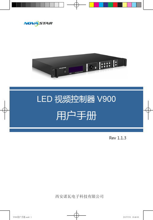
电源线一条DVI线一条USB线一条说明书一本,请按下图进行连接。
第一行:主画面1、信号源、输入源信号格式。
:按照输入输出接口将硬件设备连接后,再按照输入设置→快捷方式二:自定义分辨率设置快捷点屏快捷点屏的前提条件是:屏体规则(非异型),箱体规则,各箱体带载大小相同。
快捷点屏操作步骤:第一步显示屏上电,如箱体显示正常,进入第2步,如显示不正常,则必须先载入箱体文件,并固化至接收卡,具体操作请查看高级设置。
第二步进入“快捷点屏”的子菜单,转动旋钮,分别进入其他选项进行设置。
:a)如(n带载的箱体数必须相等(如输出设置如果辨率在某个方向上小于屏体,则屏体在该方向上会有不自动全屏播放。
此时【启用缩放】为启用,【自动全屏缩放】自动全屏缩放时,输入内容被完全缩放到屏体大小,输入内容自适应显示屏大小。
此模式适合演播内容全屏播放的情况。
自定义缩放。
此时【启用缩放】设为启用,【自动全屏缩放】自定义缩放需要执行以下操作步骤:设置输入截取,即从输入的图像中,截取输入图像的某个起始点之后的部分感兴趣的画面在显示屏上显示。
一般需第二步设置输出窗口,窗口尺寸需小于等于显示屏大小。
设置好窗口后,图像只能在窗口范围内自适应大小显示,用于在显示屏上预留边框或者是限制画面播放区域的应用场合。
按照以上两步进行设置后,显示屏仅会在设定的区域内显示输入截取的内容,如下图所示:图 5 自定义缩放效果图画面控制正常显示:正常播放当前输入源的内容。
画面黑屏:显示屏黑屏不显示。
:当画中画功能开启时,通道特效功能自动失效。
只有当画中画功能关闭时,通道切换特效功能才可以生效。
高级设置在高级设置里包含了多个主要功能的设置选项,如双画面设置、拼接带载、载入箱体配置文件、固化至接收卡、双主控热备份、高级属性、工厂复位、预设模块、自定义按键、硬件版本等。
下面章节将详细讲述每个功能。
双画面设置双画面的开关和关闭,主画面和画中画的输入源,以及画中主画面输入源/画中画输入源:主画面和画中画的输入源切换与主面板上的输入源切换按钮作用相同。
Micro LED视频拼接器诺瓦科技视频切换台N6用户使用手册完整版

用户手册多画面拼接处理器N6Rev1.0.1 NS160110161声明欢迎您选用西安诺瓦电子科技有限公司(以下简称诺瓦科技)的产品,如果本文档为您了解和使用产品带来帮助和便利,我们深感欣慰。
我们在编写文档时力求精确可靠,随时可能对内容进行修改或变更,恕不另行通知。
如果您在使用中遇到任何问题,或者有好的建议,请按照文档提供的联系方式联系我们。
对您在使用中遇到的问题,我们会尽力给予支持,对您提出的建议,我们衷心感谢并会尽快评估采纳。
版权商标本文档版权归诺瓦科技所有,未经本公司书面许可,任何单位或个人不得以任何形式对文本内容 进行复制、摘录等,违者必究。
是诺瓦科技的注册商标。
目录安全声明.................................................................................................................................................................... 1更新历史.................................................................................................................................................................... 2术语 .. (3)1概述.....................................................................................................................................................................41.1系统架构 (4)1.2软件安装 (4)2外观说明............................................................................................................................................................52.1前面板 (5)2.2后面板 (6)3信号连接............................................................................................................................................................84菜单操作 (10)4.1屏体配置 (12)4.2窗口布局 (12)4.3场景切换 (13)4.4输入设置 (13)4.5画面控制 (13)4.6高级设置 (14)4.7通讯设置 (14)4.8语言设置 (15)5系统模式.........................................................................................................................................................165.1切换台模式 (16)5.2拼接器模式 (18)6电气参数.........................................................................................................................................................207安装尺寸 ......................................................................................................................................................... 218常见问题 (22)安全声明为避免可能的危险,请按规定使用此设备。
诺瓦科技LED视频处理器LED视频拼接器VS3用户手册
产品用户手册多画面拼接处理器VS3声明 欢迎您选用西安诺瓦电子科技有限公司(以下简称诺瓦科技)的产品,如果本文档为您了解和使用产品带来帮助和便利,我们深感欣慰。
我们在编写文档时力求精确可靠,随时可能对内容进行修改或变更,恕不另行通知。
如果您在使用中遇到任何问题,或者有好的建议,请按照文档提供的联系方式联系我们。
对您在使用中遇到的问题,我们会尽力给予支持,对您提出的建议,我们衷心感谢并会尽快评估采纳。
版权 本文档版权归诺瓦科技所有,未经本公司书面许可,任何单位或个人不得以任何形式 对文本内容进行复制、摘录等,违者必究。
商标是诺瓦科技的注册商标。
安全声明为避免可能的危险,请按规定使用此设备。
如出现损坏,非专业人士请勿擅自打开维修, 请及时与本公司售后联系。
高压危险:本产品的工作电压为 100 ~ 240 V AC 。
接地:本产品通过电源的地线与大地相连,请确保接地导体的良好接地。
电磁干扰:设备应远离磁铁、马达及变压器。
防潮:请将设备置于干燥、干净的环境中。
如有液体浸入,请立即拔掉电 源插头。
远离易燃易爆危险物品。
禁止液体、金属碎片浸入机器内部,以免引起安全事故。
插座应当装在设备的附近,而且应当便于触及到。
多画面拼接处理器 VS3 用户手册目录第一章 功能简介......................................................................................... 1 前面板示意图.............................................................................................. 1 后面板示意图.............................................................................................. 2 电气参数..................................................................................................... 3 第二章 信号连接 .. (4)第三章菜单操作......................................................................................... 5 主界面 ......................................................................................................... 5 主菜单......................................................................................................... 6 屏体设置 ..................................................................................................... 6 窗口布局 ..................................................................................................... 7 场景切换..................................................................................................... 7 输入设置..................................................................................................... 7 输出设置..................................................................................................... 8 画面控制..................................................................................................... 8 高级设置................................ ..................................................................... 8 通讯设置..................................................................................................... 8 第四章 配套控制软件 .................................................................................. 9 第五章常见问题 (10)多画面拼接处理器 VS3 用户手册1)输入源被分为 A、B、C、D 四组,各路输出必须是不同组的信号,也即只有不同组的信号源可以被同时输出。
诺瓦科技LED视频处理器VS0规格书

V S0视频处理器规格书文档版本:V1.0.0文档编号:NS160000237版权所有©2018西安诺瓦电子科技有限公司。
保留一切权利。
非经本公司书面许可,任何单位和个人不得擅自摘抄、复制本文档内容的部分或全部,并不得以任何形式传播。
规格书1概述1概述VS0视频处理器是诺瓦科技推出的一款操作简易,功能丰富的纯硬件设备,支持高清多类型接口输入,基于强大的视频处理平台,可对输入源进行图像画质调整,为您带来更加灵活的画面构造体验。
采用工业级外壳,可适应复杂的操作环境,常用于商场、酒店、展览展示、电视演播中心等多种场合。
规格书2特性2特性●支持多达4路输入接口,包括1路DVI,1路HDMI1.3,1路VGA,1路USB播放,选配1路Android子卡。
●支持窗口位置、大小调整及窗口截取功能。
●安装Android子卡后,A ndroid播放源模式下,支持使用鼠标和显示器进行控制。
●支持输入源一键切换。
●支持外置独立音频。
●支持连接控台设备。
●支持输入分辨率预设及自定义调节。
●支持画面全屏缩放、点对点缩放、自定义缩放三种缩放模式。
●视频输出最大分辨率为1920×1080@60H z。
●支持2个DVI输出接口复制输出。
●支持选配2张发送卡,安装时无需拆卸机壳。
●支持创建6个用户场景作为模板保存,可直接调用,方便使用。
●前面板直观的OLED显示界面,清晰的按键灯提示,简化了系统的控制操作。
●安装Android子卡后,支持无线投屏,可投放手机或Pad画面。
规格书 3 外观后面板4 尺寸4尺寸单位: m m规格书5 应用场景5应用场景产品规格图片文件格式:视频文件格式:rvmb。
- 1、下载文档前请自行甄别文档内容的完整性,平台不提供额外的编辑、内容补充、找答案等附加服务。
- 2、"仅部分预览"的文档,不可在线预览部分如存在完整性等问题,可反馈申请退款(可完整预览的文档不适用该条件!)。
- 3、如文档侵犯您的权益,请联系客服反馈,我们会尽快为您处理(人工客服工作时间:9:00-18:30)。
4.4.7 优先级 ................................................................................................................................ 17
4.3输入设置 ........................................................................................................................................ 10
4.3.1 预设 EDID .......................................................................................................................... 10
ii
用户手册
N9
1 产品概述
1 产品概述
2 预监接口支持输入、PVW、PGM 和 AUX 预监。
图层的位置和大小等可灵活调节,支持图层边框,边框宽度和颜色可调。 支持创建 32 个用户场景作为模板保存,可直接调用,方便使用。
提供多种切换效果。
外观说明
直观的前面板彩色 LCD 显示界面,清晰的按键灯提示,简化了系统的控制操作。
4.3.2 输入画质 ............................................................................................................................. 11
4.4窗口设置 ........................................................................................................................................ 12
N9 可以搭配桌面控台 C1,使现场舞台操作更加便捷。N9 配备了全新的智能管理软件 V-Can,能够实现更加丰富的画面拼接效果。
N9 具备强大的多种类视频信号接收和处理能力,可被广泛应用于中高端租赁,舞台控
制按,键媒体中心、大功型能会议现场,展会现场、演唱会(春节晚会)指控中心等多种场
景。 输入源
网址:
4.1操作说明 .......................................................................................................................................... 8http://www.
2.3 产品尺寸 .......................................................................................................................................... 6
3 使用场景 ............................................................................................................................................................... 7
信号输入源的状态。
指示灯低亮表示有信号源接入但未使用。
1.2 产品特性
指示灯高亮表示信号源已接入且正在使用中。 指示灯灭表示没有接入信号源或接入信号异常。
LCD支显持示多屏达 9 路用于输显入示接设口备,当包前括状1态路,D以P及1.设1 双置菜链单路。,更换为 HDMI1.4、DP1.1 或 Dual link DVI 接口,2 路 HDMI1.3,可更换成 DVI/VGA/CVBS 接口,4 路 DVI,
N9
多画面 拼接 视频 处理 器
用户 手册
: :
版权所有 ©2018 西安诺瓦电子科技有限公司。 保留一切权利。
非经本公司书面许可,任何单位和个人不得擅自摘抄、复制本文档内容的部分或全部,并不得以任何形式传 播。
目录
商标声明
是诺瓦科技的注册商标。
目录
声明
欢帮迎助您和选便用利西,1 产安我品诺们瓦概深电述感子欣...科慰....技。...有.我...限.们...公.在...司编....(写...以.文...下.档...简.时...称力....诺求...瓦.精...科.确...技.可...)靠....的,...产.随...品.时...,.可...如.能...果对...本.内...文.容...档.进...为.行...您修....了改...解.或...和.变...使.更...用,....产恕...品.不...带.另...来.行...................... 1 通知。如果您在1.使1 产用品中定遇到位任...何...问....题...,...或....者...有....好...的....建...议...,....请...按....照...文....档...提...供....的...联....系...方....式...联...系....我...们....。...对...您....在...使....用...................... 中遇到的问题,我们1 会尽力给予支持,对您提出的建议,我们衷心感谢并会尽快评估采纳。
15
i
N9 用户手册
4.4.5 输入截取 ............................................................................................................................ 15
4.4.1 窗口选择 ............................................................................................................................ 14
4.4.2 窗口状态 .......................................................................................................... 14
4.4.3 输入源 ................................................................................................................................ 14
4.4.4 窗口大小 ............................................................................................................................
1.2产品特性 ..........................................................................................................................................
1
2 外观说明 ............................................................................................................................................................... 3 2.1前面板 .............................................................................................................................................. 3
支持 Genlock 同步以及和某一路输入源同步,达到输出场级同步
2.1 前面板
1
产品概述
1.1 产品定位
N9 是由诺瓦科技自主研发的高性能多画面拼接视频处理器,采用高性能的视频处理技 术,可处理和输出超高质量的图像。N9 具备强大的视频信号接收能力,可同时支持 9 路视频源输入,4 路 DVI 输出,单机带载可达 8KK,并支持多台设备级联输出。
4.5高级设置 ........................................................................................................................................ 17 4.5.1 HDCP 功能 ......................................................................................................................... 17 4.5.2 恢复出厂设置 ..................................................................................................................... 18