16 CE318太阳光度计技术手册介绍
CE318_太阳光度计技术手册

CE318太阳光度计技术手册中国气象局监测网络司编写说明为了满足中国气象局沙尘暴站业务化运行的需求,同时,为观测人员了解测量原理、对仪器进行操作和维护提供指导,为研究人员开展科研工作提供参考,有关专家和有经验的业务技术人员共同编写了本材料。
本材料由中国气象科学研究院中国气象局大气成分观测与服务中心、北京市气象局和国家卫星气象中心共同组织编写。
目 录1 概述 (1)2 系统结构及原理 (1)2.1 仪器工作原理 (1)2.1.1 大气光学厚度 (1)2.1.2 气溶胶参数 (2)2.1.3 改进Langley法 (2)2.2 仪器结构 (3)2.3 技术指标 (5)3 系统安装及操作方法 (5)3.1 系统安装 (5)3.2 操作方法 (6)3.2.1 太阳光度计的启动和关闭 (6)3.2.2 重要操作指令列表 (8)3.2.3 天空扫描测量 (12)3.2.4 自动模式测量 (13)3.3 日常检查 (14)4 系统维护与校准 (14)4.1 系统维护 (14)4.1.1 检查系统的完整性 (14)4.1.2 检测电池电压 (14)4.1.3 检测仪器的时钟 (15)4.1.4 检测机器人臂和光学头是否水平 (15)4.1.5 检测仪器的跟踪和对准器 (15)4.2 系统定标 (15)5 数据及格式 (16)6 安全及注意事项 (16)7 附录 (18)7.1 日检查表 (18)7.2 周检查表 (19)1 概述大气气溶胶光学厚度的测量可反映气溶胶粒子对太阳辐射的消光作用。
世界气象组织的全球大气观测网(WMO-GAW )将大气气溶胶光学厚度的观测作为基本观测项目,目的是对全球大气气溶胶的变化趋势进行长期观测,进而研究其对全球和局地气候变化的影响。
同时气溶胶光学厚度的地基观测结果,也是对卫星光学遥感校准的一种重要的手段。
WMO-GAW 推荐了两种通过直接测量太阳分光辐射求出气溶胶光学厚度的方法,一种方法是采用一组短波截止滤光片和直接日射表相配合进行测量,另外一种是使用太阳光度计的测量方法。
AATCC测试方法16-2003

汇报……………………………………………………………………………………………………………28 精密度和偏差………………………………………………………………………………………………29-30 参考书目………………………………………………………………………………………………………31 注释……………………………………………………………………………………………………………32 附录…………………………………………………………………………………………………………A-C
2.原理
2.1 用于测试的纺织材料的样品和与之一致的比较标准应该同时暴露在符合的光源中。测试品的耐光色牢 度可以通过以下三种方式进行测算:把曝光部分的颜色变化与测试样本上的标记对照部分进行比较,运用 AATCC 色变高度与未经曝光的原材料进行比较;或者通过颜色测量仪来测算。在同步曝光条件下与 AATCC 蓝羊 毛耐光度标准进行系列比较,从而得出耐光度的分级。
3.8 光照色牢度:在日光或人造光源下,材料对自身色彩特征发生改变的抗耐性。 3.9 红外线辐射:一种放射性能量,其单色成分的波长小于 1mm,长于可见光。 注:红外线辐射的光谱范围并未完全界定,可能根据使用者而改变,根据 CIE 委员会 E-2.1.2,在 780nm 和 1nm 光谱范围之间进行了区分: IR—A IR—B IR—C 780-1400nm 1.4-3μm 3μm-1mm
1. 目的及适用范围
1.1 这种测试方法提供了确定纺织材料耐光色牢度的一般原则和操作步骤。 这些测试选择适用于所有类型 的纺织材料和色料,也应用于纺织材料的修饰和处理。 测试选择包括: 1----连续的碳电弧灯光 2----交替的碳电弧灯光 3----连续的氙气弧灯光,黑色面板选择 4----交替的氙气弧灯光 5----连续的氙电弧灯光,黑色标准选择 6----玻璃后的日光 1.2 这种测试选择不是明确的用于特殊应用程序的加速测试,或者可以适用于其他的。在任何色牢度测试 和实际曝光应用之间的联系必须通过契约体来确定,且必须是一致。 所在部分 术语……………………………………………………………………………………………………………3 安全防范………………………………………………………………………………………………………4 应用和限制……………………………………………………………………………………………………5 仪器和材料……………………………………………………………………………………………………6 比较标准………………………………………………………………………………………………………7 测试样品准备…………………………………………………………………………………………………8 机器选择条件…………………………………………………………………………………………………9 校准和检定………………………………………………………………………………………………10-12 AATCC 褪色单元测量……………………………………………………………………………………13-14 机器曝光操作步骤………………………………………………………………………………………15-18 日光曝光操作步骤………………………………………………………………………………………19-22 结果评估…………………………………………………………………………………………………23-27
CE318型太阳光度计关键技术及误差分析
CE318型太阳光度计关键技术及误差分析卞良1,2李保生1李东辉2(1合肥工业大学仪器科学与光电工程学院安徽合肥230009;2中国科学院遥感应用研究所北京100101)摘要:大气气溶胶地基遥感监测由于其精度高、参数多、易于维护等特点,近几十年里发展迅速。
CE318型太阳光度计作为地基遥感监测的基本仪器,在美国NASA建立的气溶胶自动监测网AERONET的影响下,越来越普及。
中国正在逐步建立和完善以CE318为基础的气溶胶自动监测网。
本文简单介绍了CE318型太阳光度计的基本结构和功能,详细介绍了其高精度分光探测、高精度太阳跟踪和自动化测量三个方面的关键技术,并对仪器误差来源做了深入分析,为基于CE318的气溶胶地基遥感监测提供支持。
关键词:CE318;太阳光度计;地基遥感;关键技术;误差分析中图分类号:P407;P111.41;P122Key Technologies and Error Analysis of Sun Photometer CE318Bian Liang 1,2, Li Baosheng1, Li Donghui2(1 School of Instrument Science and Opto-electronics Engineering, Hefei university of Technology, Anhui Hefei 230009, China; 2 Institute of Remote Sensing Applications, Chinese Academy of Sciences, Beijing 100101, China)Abstract: Due to its high precision, multi-parameter, easy to maintain, Ground-Based Remote sensing monitoring of atmospheric aerosol has developed rapidly in recent decades. Sun photometer CE318 is the main instrument for ground-based remote sensing monitoring. It is becoming increasingly popular under the influence of AERONET established by NASA. The automatic aerosol remote sensing monitoring network based on CE318 is improving gradually in China. This presentation briefly introduced the basic structure and function of CE318 sun photometer, and presented in detail its three key technologies of high precision spectrometer detection, high precision sun-tracking and automated measurement, in addition, analyzed its error sources. These studies provide support to aerosol remote sensing monitoring based on CE318.Key words:CE318; Sun photometer; Ground-based remote sensing; Key technologies; Error analysisCE318系列自动跟踪扫描太阳光度计(简称:CE318)是由法国CIMEL公司生产的高精度太阳和天空辐射测量仪器,是目前进行大气气溶胶地基遥感观测的基本仪器。
CE318型太阳光度计定标方法研究
置为阈值,按照中心波长由长到短阈值分别为
253、266、372、278、99、208、89。图 1 显示了 2020
年12月30日500 nm原始观测值曲线和处理前
后均值曲线的变化。图1a显示原始数据在多个
54
陕西气象
2021(4)
时间点上三次观测值有明显的差异,未经处理的 三次观测均值曲线如图lb所示,在1 0 :17—11:
52
陕西气象
董金芳,何慧娟,王娟.CE318型太阳光度计定标方法研究*+• 陕西气象&0 21(4) = 52-56. 文章编号! 0 0 6-4354(20 21) 04- 0 0 52- 0 5
2 02 0 ⑷
CE318型太阳光度计定标方法研究
董金芳12,何慧娟#,王娟#
(1.陕西省农业遥感与经济作物ห้องสมุดไป่ตู้象服务中心,西安 71 0 0 16; 2.陕西省气象局秦岭和黄土高原生态环境气象重;实验室,西安 71 0 0 16)
(2)
LnV =LnV0 —LnR2 +Ln"g—3#。 (3) 在大气状态稳定的情况下,大气垂直气溶胶
光学厚度#保持不变,以相对大气质量3为自变 量工,LnV SLnR2为因变量夕,在没有气体吸收的
通道"g近似为14和夕满足斜率为一#、截距为 LnV0的线性关系,如式(4)所示。
LnV + LnR2 = —3#+ LnV0。
根据Beer-Lambert定律阐述的物质对光的
太阳光度计天空辐射亮度观测
太阳光度计天空辐射亮度观测的浅析【摘要】目前ce-318太阳光度计被各广泛应用于气象观测中,为了使人们了解ce-318太阳光度计工作原理、数据存储格式及解读方法,使观测数据更好地发挥作用,本文介绍了太阳光度计在天空观测(主要在大气气溶胶的观测)方面的应用,并将根据观测资料讨论太阳光度计的后续研究方向。
【关键词】太阳光度计;天空亮度;气溶胶1.引言全自动太阳光度计ce-318,是一种自动跟踪扫描太阳辐射计。
测得的直射太阳辐射数据和天空扫描数据,主要用来计算大气通透率,反演气溶胶光学和其他特性,如粒度谱、相函数等。
大气气溶胶是由固态或液态的质粒分散到空气中形成的分散体系。
悬浮在大气中的大气气溶胶颗粒的直径通常小于10,它们对大气辐射传输和水循环均有重要的影响[1]。
近年来先后出现的臭氧层的破坏、酸雨的形成、北极霾、烟雾事件[2]等现象都与大气气溶胶密切相关。
由于气溶胶对天空的亮度存在很大的影响,因而,我们可以利用ce-318 获得的太阳直接辐射数据来反演南京地区的大气气溶胶光学厚度,并对反演所得的结果进行分析,从而判断南京地区天空亮度的日变化和随季节的不同或天气状况的不同而产生的变化。
2.测量仪器和测量原理2.1 ce-318型太阳光度计图1 ce-318太阳光度计结构示意图[3]本文采用的是测量仪器是全自动太阳分光光度计ce-318,待测的天空亮度能直接从测量仪器中读出。
ce-318由一个光学头、一个控制箱和一个双轴步进马达系统组成,光学头带有两个瞄准筒:一个用于测量太阳直射辐射不带聚光透镜,另一个用于天空辐射测量带有聚光透镜。
在光学头上还装有四象限探测器用于太阳自动跟踪时的微调。
控制箱内装有2个微处理器,分别用于数据获取和步进马达系统的控制。
在全自动测量状态,如附设的“湿度传感器”探测到降雨,控制箱将置光度计于停机状态,以保护仪器的光学系统。
步进马达系统具有方位和测量高度角两个自由度,由时间方程来控制太阳的初步跟踪,用四象限探测器系统作精密跟踪。
LCM系列天文望远镜说明书

巡天模式 ........................................................................... 24 星座漫游 ........................................................................... 24 方向键...................................................................................... 25 速率键...................................................................................... 25 设置步骤.................................................................................... 25 跟踪模式(Tracking Mode) .......................................................... 25 跟踪速率(Tracking Rate) ............................................................ 26 显示时间-位置 ...................................................................... 26 用户自定义目标 ..................................................................... 26 获取赤经赤纬 ....................................................................... 27 Goto 赤经赤纬....................................................................... 27 识别(Identify) ................................................................... 27 望远镜设置功能 .............................................................................. 28 消齿隙(Anti-backlash) ............................................................ 28 旋转限制(Slew Limits) ............................................................ 28 筛选限制(Filter Limits) .......................................................... 29 方向键(Direction Buttons) ........................................................ 29 Goto 接近(Goto Approach) .......................................................... 29 缠绕(Cordwrap) ................................................................... 29 实用工具(UTILITY FEATURES) ................................................................... 30 GPS 开/关(GPS On/Off) ............................................................ 30 亮度控制(Light Control) .......................................................... 30 出厂设置(Factory Setting) ........................................................ 30 系统版本(Version) ................................................................ 30 获取轴位置信息 ..................................................................... 30 Goto 轴位置......................................................................... 30 休眠(Hibernate) .................................................................. 30 太阳菜单(Sun Menu) ............................................................... 31 滚动菜单 ........................................................................... 31 GoTo 校准(Calibrate Goto) ......................................................... 31 设置基座位置(Set Mount Position) ................................................. 31 3
ZG8150行内光度仪技术手册说明书
ZG8150Inline Glossmeter Technical ManualDocument InformationDocument Revision: 1.1Revision Date: -Document State: ReleasedCompany: Proceq SARingstrasse 2CH-8603 SchwerzenbachSwitzerlandClassification: Manual for inline userRevision History0.8 Feb 6, 2020 CSAR Initial documentSGIA Add drawings0.9 April 30, 2020 PEGG New formatting and text revision1.0 August 10, 2020 PEGG Corrections and final formatting 1.1 April 21, 2022 PEGG Dimensional drawing correctedContent1Introduction (1)1.1Scope of this document (1)2Mounting of the device (2)3Dimensional Drawings (3)3.1Mounting Example – with custom mounting plate (4)3.2Mounting Tolerances (5)4Connection setup (6)4.1USB connection setup (6)4.2RS232 connection setup (7)4.3Firmware update (8)5Communication protocol (9)5.1Command and return string (9)5.2Transaction ID (TID) (9)5.3Parameter “AngleBinary” (10)5.4Invalid measurement values (10)6Commands (11)6.1 2 – AdvancedMeasureValue (11)6.2 3 – StartScan Measurement (11)6.3 5 – StopScanMeasurement (12)6.48 – SetFlash (13)6.512 – GetFlash (13)6.616 – StartContinuousMeasurement (14)6.718 – StopContinuousMeasurement (14)6.828 – GetIsOnStandard (14)6.953 – LaserEnable (16)6.1056 – Error (16)6.1164 – ResetDevice (17)6.1270 – AdvancedUserCalibration (18)6.1378 – AcceptUserCalibration (18)Legal NoticesThis document can be changed at every time and without any prenotification or announcement.The content of this document is intellectual property of Proceq SA and prohibited to be copied neither in a photomechanical or electronic way, nor in excerpts, saved and/or be passed on to other persons and institutions.The features described in this instruction manual represent the complete technology of this instrument. These features are either included in the standard delivery or available as options at additional costs.Illustrations, descriptions as well as the technical specifications conform to the instruction manual at hand at the time of publishing or printing. However, Proceq SA policy is one of continuous product development. All changes resulting from technical progress, modified construction or similar are reserved without obligation for Proceq to update.Some of the images shown in this instruction manual are of a pre-production model and/or are computer generated; therefore the design/features on the final version of this instrument may differ in various aspects.The instruction manual has been drafted with the utmost care. Nevertheless, errors cannot be entirely excluded. The manufacturer will not be liable for errors in this instruction manual or for damages resulting from any errors.The manufacturer will be grateful at any time for suggestions, proposals for improvement and references to errors.1 IntroductionThe ZG8150 is a glossmeter for use in a production test system. With a dedicated cable it can be connected to a USB or RS232 interface on the host (e.g. PC). For that a dedicated cable is used and the device has to be configured accordingly.1.1 Scope of this documentThis document is an instruction manual for the ZG8150 Inline Glossmeter.It describes in technical details, the mounting and explains the connection setup, the protocol format, the command set and their parameters, the answer-strings of the device as well as possible error reports.2 Mounting of the deviceTo integrate the ZG8150 into a production line, the device can be mounted to fixtures or robotic arms.To facilitate the mounting, the device has a threaded hole on the top and two mounting guide holes. Follow the stepsRemove cap for mountingCap can be pierced with a drill and put back onDrill diameter: 4.5mm + 6mm3 Dimensional Drawings3.1 Mounting Example – with custom mounting plateThe following example shows how the ZG8150 can be mounted on a custom made mounting plate, which allows versatile mounting options to robot arms or fixtures.NOTE:This mounting plate is for reference purposes to make your integration easier and not available as a product.3.2 Mounting TolerancesIn order to guarantee the specified performance, the device shall be mounted to fulfill the following mounting tolerances.4 Connection setupThe glossmeter has a USB connection and can be connected to a USB or RS232. Interface on the host (e.g. PC). For that a dedicated cable is used and the device must be configured accordingly.4.1 USB connection setupTo connect the device to a USB port a USB type C to type A cable is used. The device needs to be setup for USB connection.Connector Type Description Setting Value1 A (male) Plugged on PC side Baudrate 1152002 C (male) Plugged on device side Data Bits 8Stop Bits 1Parity NoneFlow Control None4.2 RS232 connection setupTo connect the device to a RS232 port the RS232 connection kit is used.This consists of1. a USB Y-cable2. a USB-to-RS232 converter3. a gender changer adapter1 A (female) Plugged to the RS232 adapter2 C (male) Plugged on device side3 A (male) Plugged to power 5V (e.g. PC side)In order to communicate to a RS232 port the device needs to be setup for RS232 communication (see section 6).The serial port of the computer has to be set to the following communication settings:Data Bits 8Stop Bits 1Parity NoneFlow Control None4.3 Firmware updateA firmware update can only be performed view a USB connection. Therefore the USB connection setup (see 4.1) is required.If the device is used in USB setup, the device can be connected to a PC via USB and the firmware can be updated using the “pqUpgrade” tool.If the device is used in RS232 setup, the device needs to be configured for USB setup first.There are two ways to switch to USB connection setup:1. Using a command string (see 6.4) After the communication is set to a USB connectionsetup, the device resets and starts in the selected communication setup.2. Press the measurement button of an unplugged device. Plug in the USB cable (USB set-up)connected to the PC and wait 10s before release the measurement button. Then the update tool “PqUpgrade” will find the device. “PqUpgrade” will start the device in USB virtual comport setup. In order to return to the same communication setup as before the update a reset is required.5 Communication protocolThe communication with the ZG8150 is completely string based. All commands are composed of ASCII-character strings. This allows an easy control of the device, for example with a commercially available terminal program such as “HyperTerminal”.5.1 Command and return stringThe communication works synchronous, with the following communication scheme:3. A command is sent to the device4. The command is executed5. and a return string is sent from the deviceOnly after a complete sequence a new command is accepted.In scan mode or continuous mode another scheme is used:6. a command to start the scan mode or continuous mode is sent to the device7. the device starts the respective mode8. and sends data, until the mode is stoppedOnly after this mode is stopped, new commands can be sent.A command string is basically structured like this:CMD | TID | PARAMS:CMD The command defines which operation is executed.TID The transaction ID can be used to identify a communication transfer.PARAMS The parameters are added after the TID. The number of parameter can differ from command to command.For separation of the different values the pipe character “|” (ASCII 0x7C) is used.As terminator is the character colon “:” (ASCII 0x3A) used.e.g. 2|xy|3:5.2 Transaction ID (TID)The recommended value ranges of the 2 ASCII characters are following:0x21…0x2F0x3B (0x40)0x42…0x7B0x7D…0x7EReturn strings from device which are not triggered explicitly by user side will use only ASCII numbers (0x30…0x39).5.3 Parameter “AngleBinary”The parameter “AngleBinary” includes the information which geometries are selected. The value corresponds to binary coded integer (active high) and the bit field is as follows:0x21…0x2FValue0 (inactive) 0 (inactive) 1 (active) 10 1 0 20 1 1 31 0 0 41 0 1 51 1 0 6A0 always denotes the smallest angle according to the perpendicular to the measuring plane. For example a device with the geometries 20°/60°/85°, A0 would be 20°, A1 = 60°, A2 = 85°. 5.4 Invalid measurement valuesIt can happen that a measurement return values smaller than zero.-1 No measurement value-2 Overflow6 CommandsIn this section the command strings supported by the glossmeter are listed. Some possible access by commands not described is provided for other use than inline (e.g. factoryconfiguration/calibration/diagnostic).6.1 2 – AdvancedMeasureValueThis command executes a single measurement.Command: 2Command string: 2|TID|AngleBinary:Return string: 2|TID|AngleBinary|Unit|ValueAn:Parameter:AngleBinary Angle combinationValueAn Measured value per angle n (n = 0…2), format %4.1fUnit GU or %Send 2|xy|3: Command: 2TID: xyAngleBinary: 3 (angle A0 and A1) Receive 2|xy|3|GU|91.2|94.5: Command: 2TID: xyAngleBinary: 3 (angle A0 and A1)Uint: GUMeasured values: A0 = 91.2, A2 = 94.56.2 3 – StartScan MeasurementThis command starts the scan measurements until the device receives the stop command. Scan measurement mode executes measurements at the fastest possible rate and sends them consecuteively. Do not send other commands while scan mode is active. If you want to sent another command, first execute the StopScanMeasurement command.Command: 3Command string: 3|TID|AngleBinary:Return string: 3|TID|AngleBinary|Unit|ValueAn:Parameter:AngleBinary Angle combinationValueAn Measured value per angle n (n = 0…2), format %4.1fUnit GU or %Send3|xy|2: Command: 2TID: xyAngleBinary: 2 (angle A1)Receive3|xy|2|GU|70.5:3|00|2|GU|70.9:3|01|2|GU|71.0:3|02|2|GU|70.7: Command: 2TID: xy, 00, 01, 02, …AngleBinary: 2 (angle A1) Uint: GUMeasured values:…A1 = 70.5, 70.9, 71.0, 70.7, …6.3 5 – StopScanMeasurementThis command stops the scan measurements.Command: 5Command string: 5|TID:Return string: 5|TID:Send 5|xy: Command: 5TID: xyReceive 5|xy: Command: 5TID: xy6.4 8 – SetFlashThis command provides write access to angle independent settings.Command: 8Command string: 8|TID|Index|Data:Return string: 8|TID:Parameter:Index Index of the setting (see Index table in 6.5)Data Value of the particular settingSend8|xy|710|1000: Command: 8TID: xyIndex: 710Data: 1000Receive8|xy: Command: 8TID: xy6.5 12 – GetFlashThis command provides read access to angle independent settings.Command: 12Command string: 12|TID|Index:Return string: 12|TID|Data:Parameter:Index Index of the settingData Value of the particular setting500 Serial Number Read only string.503 Angle Binary Read only supported angles.Value range: 1-7 (integer)710 MsrIntervalTime Measure interval time for continuousmode.Possible values in milliseconds: 500,1000, 1500, 2000, 2500, 3000, 3500,4000, 4500, 50001100 UsbSettings Communication setting.USB setup: 0 (integer)RS232 setup: 1 (integer)1560 Units Measurement unitsGloss units: 0 (integer)Percent: 1 (integer)Send 12|xy|710: Command: 12TID: xyIndex: 710Receive 12|xy|1000: Command: 12TID: xyData: 10006.6 16 – StartContinuousMeasurementThis command starts the continuous measurements until the device receives the stop command. Command: 16Command string: 16|TID|AngleBinary:Return string: 16|TID|AngleBinary|Unit|ValueAn:Parameter:AngleBinary Angle combinationValueAn Measured value per angle n (n = 0…2), format %4.1fUnit GU or %Send 16|xy|3: Command: 16TID: xyAngleBinary: 3 (angle A0, A1)Receive 16|xy|3|GU|85.3|87.6:16|35|3|GU|87.5|89.4:16|36|3|GU|89.4|92.3:16|37|3|GU|91.2|94.5:…Command: 16TID: xy, 35, 36, 37, …AngleBinary: 3 (angle A0, A1) Uint: GUMeasured values:A0 = 85.3, 87.5, 89.4, 91.2, …A1 = 87.6, 89.4, 92.3, 94.5, …6.7 18 – StopContinuousMeasurementThis command stops the continuous measurements.Command: 18Command string: 18|TID:Return string: 18|TID:Send 18|xy: Command: 18TID: xyReceive 18|xy: Command: 18TID: xy6.8 28 – GetIsOnStandardThis command returns the information if the device is placed on the working standard or not. Command: 28Command string: 28|TID:Return string: 28|TID|Data:Parameter:Data 0 = is not on standard, 1 = is on standardSend 28|xy: Command: 18TID: xyReceive 28|xy|1: Command: 18TID: xyData: 1 (is on standard)6.9 53 – LaserEnableThis command enables or disables the laser of the glossmeter.Command: 53Command string: 53|TID|Data:Return string: 53|TID:Parameter:Data 0 = disable laser, 1 = enable laserSend 53|xy|1: Command: 53TID: xyData: 1 (enable laser)Receive 53|xy: Command: 53TID: xy6.10 56 – ErrorThis command returns the error of any command.Command: 56Command string: -Return string: 56|TID|Command|Error:Parameter:Command Command caused the errorError Error code-1 UNDEFINED_ERROR0 NO_ERROR1 OPCODE_NOT_FOUND No command with this codeexists.9 NO_STANDARD_VALUE No valid standard value is used.10 DEVICE_NOT_ON_WORKING_STANDARD Device is not placed on theworking standard.12 VALUE_OUT_OF_RANGE Value is out of range.13 PARSE_ERROR The format of the send string isnot correct or wrong sendparameters are used.14 PARAMETER_ERROR The index of a setting is wrong.30 NO_ACCESS_RIGHTS The user has no access rights.31 ACCESS_DENIED No access because it is notpossible to access the resource.32 BLOCK_CMD_ACCESS The access is blocked becauseanother action blocks it.40 HW_ERROR HW error occurred.61 TIMEDATE_INCONSISTENT Time check is not consistent. 201 FLASH_WRITE_FAILED Writing ot the settings failed. 202 FLASH_READ_FAILED Reading of the settings failed.Send 8|xy|0|3: Command: 8TID: xyIndex: 0Data: 3Receive 56|xy|0|30: Command: 56TID: xyCommand: 0Error: 306.11 64 – ResetDeviceThis command performs a reset.Command: 64Command string: 64|TID:Send 64|xy: Command: 64TID: xy6.12 70 – AdvancedUserCalibrationThis command is used to execute a user calibration.Command: 70Command string: 70|TID|AngleBinary|Cal2Std|CalValue:Return string: 70|TID|Deviation:Parameter:AngleBinary A single angle can be selectedCal2Std 0 = calibrate to working standard, 1 = calibrate on second standard CalValue Calibration value, units depends on setting, if Cal2Std = 0 is CalValue = 0 Deviation Deviation in ppm (e.g. 6235 = 0.6235%) relative to the used sampleSend 70|xy|1|0|0: Command: 70TID: xyAngleBinary: 1 (angle A0)Cal2Std: 0 (working standard)CalValue: 0Receive 70|xy|2020: Command: 70TID: xyDeviation: 2020ppm (0.2020%)6.13 78 – AcceptUserCalibrationThis command is used to accept the executed AdvancedUserCalibration. This valid after user calibration or an accept command. If another command is executed the user calibration is not valid anymore.Command: 78Command string: 78|TID|AngleBinary:Return string: 78|TID:Parameter:AngleBinary A single angle which was user calibrated before.Send 78|xy|2: Command: 78TID: xyAngleBinary: 2 (angle A1)Receive 78|xy: Command: 78TID: xyFor safety and liability information, please download at /downloads Subject to change. Copyright © 2020 by Proceq SA, Schwerzenbach. All rights reserved.P ROCEQ E UROPERingstrasse 2CH-8603 Schwerzenbach Switzerland+41 43 355 38 00**********************P ROCEQ UK L TD.Bedford i-lab, Priory Business Park Stannard WayBedford MK44 3RZUnited Kingdom+44 123 483 45 15******************P ROCEQ USA,I NC.117 Corporation Drive Aliquippa, PA 15001U.S.A.+1 724 512 03 30*******************P ROCEQ A SIA P TE L TD1 Fusionopolis Way#20-02 Connexis South Tower 138632 Singapore+65 6382 3966********************P ROCEQ R US LLCUl. Optikov 4korp. 2, lit. A, Office 410197374 St. PetersburgRussia+7 812 448 35 00**********************P ROCEQ M IDDLE E ASTP. O. Box 8365, SAIF Zone,Sharjah,United Arab Emirates+971 6 557 8505**************************P ROCEQ SAO L TD.Rua Paes Leme, 136, cj 610 Pinheiros, São PauloBrasil Cep. 05424-010+55 11 3083 38 89****************************P ROCEQ C HINAUnit B, 19th FloorFive Continent International Mansion, No. 807Zhao Jia Bang RoadShanghai 200032+86 21 631 774 79*********************。
太阳能热水器控制仪使用说明书

太阳能热水器控制仪使用说明书LG GROUP system office room 【LGA16H-LGYY-LGUA8Q8-LGA162】太阳能热水器控制仪使用说明书太阳能热水器使用说明,一般情况下也就是说的太阳能热水器控制仪的使用方法,在这里我们拿最常用的西子控制仪说明书,为大家讲解一下使用方法,希望对大家在使用过程中减少一些疑难问题,方便大家使用。
TMC至尊全天候测控仪使用说明书【主要技术指标】1.使用电源:220VAC 功耗:<5W2.测温精度:±2℃3.测温范围:0-99℃4.控温精度:±2℃5.水位分档:五档环形显示6.可控水泵或电热带功率:≤500W7.可控电加热功率:≤1500W 可选:3000W8.漏电动作电流:≤10mA/9.电磁阀参数:直流DC12V,可选用有压阀或无压阀有压阀工作压力:~无压阀工作压力:,适用于水箱供水或低压供水10.广域亮彩显示屏低功耗:<【主要功能】1.北京时间:实时显示北京时间2.水位预置:可预置加水水位50、80、100%3.水温预置:可预置加热温度范围:30℃-80℃,定时加热若不需要启动电加热,可预置为00℃4.水温指示:显示太阳能热水器内部实际水温5.水位指示:显示太阳能热水器内部所存水量6.缺水提示:当水位从高变低,出现缺水状态时,蜂鸣报警,同时20%水位闪烁7.缺水上水:当水位从高变低,出现缺水状态时,延时30分钟自动上水至预置水位8.手动控制:可手动启动上水、加热,在操作时首先显示预置的水位或水温,用户可利用▲、▼键调整预置参数,确认后,启动上水、加热,也可手动关闭。
启动加热时水位若低于50%,则先启动上水再加热。
正在加热时水位低于50%自动关闭加热,保护电加热管。
启动手动上水时,若实际水位大于等于预置水位时,测控仪自动上调预置水位,以保证用户上水需求,启动手动加热时,若实际水温大于等于预置水温时,自动上调预置水温,以保证用户加热需求,建议用户预置水温不超过60℃9.自选模式:有智能、定时、温控三种模式可选定时模式:可设定二次定时上水、二次定时加热,原厂设置定时上水第一次9:00上水至100%水位,第二次15:00启动上水至100%水位。
太阳光度计-试验室管理处
大型精密仪器设备购置申请论证报告
仪器设备名称太阳分光光度计
项目名称气溶胶污染对于植被的生长的影响
项目负责人梁勤欧
填表日期2017-07-22
实验室管理处制
填表说明
1.此表须在学院申购该设备前填写完成,并与申购计划一起上报有关部门。
2.单价10万元及以上仪器设备的申购均需填写此表。
单价10-40万元的仪器设备由各学院自行组织校内专家论证、评议;单价40万元以上的仪器设备由各学院组织校内外专家(其中必须有校外专家)论证、评议,项目经费、设备管理等部门参与。
3.此表填写必须使用碳素墨水钢笔或计算机激光打印。
4.此表一式2份(如设备为进口设备,需提交3份)。
Winner318激光粒度分析仪使用说明书

要保持各光学器件的清洁,以免影响测试效果。
调试光路时,注意千万不要碰触光电探测器〔光电探测器为激光粒度仪测试的核心部件〕,以免探头损坏,影响测试结果。
不要轻易擦拭光学镜面,以免划伤,引起测量误差。
严禁带电插拔串行口通讯电缆,插拔时仪器与电脑必须都关闭。
未经允许,私自拆卸引起的后果,由用户自己承担。
2.打开仪器接收区一侧的机罩,检查从探测器阵列中心孔中射出的激光束,如在远处形成一均匀规则的绿色光斑,可认为对中正常。如果光斑不完全或亮度不匀,应按[第四篇维护与保养:4.4调试光路]中的方法重新调节光路。
3.运行微纳激光粒度仪分析软件。
4.单击“测试”菜单中的“信息设置”。
5.在打开的“测试信息设置”对话框中单击“其他信息设置”选项卡,选择正确的端口、机型、量程及测试结果保存时间间隔,然后单击“确定”关闭对话框。
式中A---------相对误差〔%〕;
-------中位径十次测量平均值〔µm〕;
-----标准物质中位径标准值〔µm〕。
假设A≤3%,则说明仪器测量的准确度满足要求。
2.体积中位径测量重复性的检定
仪器在同一条件下,用同一标准物质一次取样连续测定十次,D50相对标准偏差△S即为重复性。
式中S -------测量标准偏差〔µm〕;
3.4
测试工作结束后,单击“查看”菜单中的“关闭视图”或者单击测试窗口。然后利用Winner3.0专家系统软件可对测试保存数据进行各种处理,详细情况请参阅《微纳激光粒度分析软件用户手册》。
第四篇
4.1
仪器激光束的存在与否,是能否进行测试的重要一环。接通粒度仪电源,正常情况下,测试区应该有一束均匀规则平行激光光束通过,假设无激光束,打开激光发射区一侧机罩,可以直接看到激光器输出的激光:假设无输出,请参阅[第八篇故障1]。
太阳能热水器控制仪使用说明书

太阳能热水器控制仪使用说明书第一篇:太阳能热水器控制仪使用说明书太阳能热水器控制仪使用说明书太阳能热水器使用说明,一般情况下也就是说的太阳能热水器控制仪的使用方法,在这里我们拿最常用的西子控制仪说明书,为大家讲解一下使用方法,希望对大家在使用过程中减少一些疑难问题,方便大家使用。
TMC至尊全天候测控仪使用说明书【主要技术指标】1.使用电源:220VAC功耗:<5W2.测温精度:±2℃3.测温范围:0-99℃4.控温精度:±2℃5.水位分档:五档环形显示6.可控水泵或电热带功率:≤500W7.可控电加热功率:≤1500W可选:3000W8.漏电动作电流:≤10mA/0.1s9.电磁阀参数:直流DC12V,可选用有压阀或无压阀有压阀工作压力:0.02MPa~0.8MPa无压阀工作压力:0.0MPa,适用于水箱供水或低压供水10.广域亮彩显示屏低功耗:<0.5W【主要功能】1.北京时间:实时显示北京时间2.水位预置:可预置加水水位50、80、100%3.水温预置:可预置加热温度范围:30℃-80℃,定时加热若不需要启动电加热,可预置为00℃4.水温指示:显示太阳能热水器内部实际水温5.水位指示:显示太阳能热水器内部所存水量6.缺水提示:当水位从高变低,出现缺水状态时,蜂鸣报警,同时20%水位闪烁7.缺水上水:当水位从高变低,出现缺水状态时,延时30分钟自动上水至预置水位8.手动控制:可手动启动上水、加热,在操作时首先显示预置的水位或水温,用户可利用▲、▼键调整预置参数,确认后,启动上水、加热,也可手动关闭。
启动加热时水位若低于50%,则先启动上水再加热。
正在加热时水位低于50%自动关闭加热,保护电加热管。
启动手动上水时,若实际水位大于等于预置水位时,测控仪自动上调预置水位,以保证用户上水需求,启动手动加热时,若实际水温大于等于预置水温时,自动上调预置水温,以保证用户加热需求,建议用户预置水温不超过60℃9.自选模式:有智能、定时、温控三种模式可选定时模式:可设定二次定时上水、二次定时加热,原厂设置定时上水第一次9:00上水至100%水位,第二次15:00启动上水至100%水位。
CE318太阳光度计常见故障与处理方法的探讨
CE318太阳光度计常见故障与处理方法的探讨摘要:介绍基于兰利(Langley)法通过直接测量太阳分光辐射获取气溶胶光学厚度的在线观测系统CE318太阳光度计在日常运行中出现的故障情况,分析和说明故障出现原因,并给出处理方法。
为正在使用或将要使用此设备的台站人员提高对仪器的使用、维护和检修能力,也为提高仪器运行的稳定性和数据的可用率提供可靠的保障。
关键词:CE318太阳光度计,故障,处理方法引言大气气溶胶光学厚度的测量可反映气溶胶粒子对太阳辐射的削弱作用。
CE318型太阳光度计,是法国CIMEL公司制造的一种自动跟踪扫描太阳辐射计。
该仪器在可见近红外波段有8个光谱通道,它不仅能自动跟踪太阳测量太阳直接辐射,而且还能进行太阳等高度角天空扫描、太阳主平面扫描和极化通道天扫描。
CE318能自动存储测量数据,并在测量完成后传输到计算机保存,还可以通过卫星采集平台远程传输数据。
CE318型太阳光度计测量得的直射太阳辐射数据和天空扫描数据,主要用来计算大气通透率,反演气溶胶光学和其他特性。
1仪器构造及原理1.1 仪器构造[1]CE318型太阳光度计主要由两部分组成:(1)仪器主体:传感器头部、扫描步进马达和机械臂。
(2)控制箱:由一个控制模块组成,提供软件控制预定的扫描和采样指令,获取数据,内置电池。
1.2 工作原理[1]大气总的光学厚度由分子散射(瑞利散射)、气体吸收消光(如臭氧、水汽)和气溶胶散射三部分组成,表达式为:其中瑞利厚度由地面气压值计算,在可见近红外波段主要是臭氧和水汽的吸收。
在没有气体吸收的通道式中可以忽略,从总的光学厚度减去瑞利光学厚度,可以计算气溶胶的光学厚度,大气总的光学厚度利用兰利(Langley)法计算。
1.3 技术指标[1](1)由太阳直接辐照度观测计算大气透过率。
(2)垂直气溶胶光学厚度在大气质量数为2时的精度是±(0.01~0.02)。
(3)由天空辐射测量可计算出的气溶胶在0.1~3um范围内的尺度谱分布,它用于辐射传输计算。
CE318 太阳光度计技术手册
CE318太阳光度计技术手册中国气象局监测网络司编写说明为了满足中国气象局沙尘暴站业务化运行的需求,同时,为观测人员了解测量原理、对仪器进行操作和维护提供指导,为研究人员开展科研工作提供参考,有关专家和有经验的业务技术人员共同编写了本材料。
本材料由中国气象科学研究院中国气象局大气成分观测与服务中心、北京市气象局和国家卫星气象中心共同组织编写。
目 录1 概述 (1)2 系统结构及原理 (1)2.1 仪器工作原理 (1)2.1.1 大气光学厚度 (1)2.1.2 气溶胶参数 (2)2.1.3 改进Langley法 (2)2.2 仪器结构 (3)2.3 技术指标 (5)3 系统安装及操作方法 (5)3.1 系统安装 (5)3.2 操作方法 (6)3.2.1 太阳光度计的启动和关闭 (6)3.2.2 重要操作指令列表 (8)3.2.3 天空扫描测量 (12)3.2.4 自动模式测量 (13)3.3 日常检查 (14)4 系统维护与校准 (14)4.1 系统维护 (14)4.1.1 检查系统的完整性 (14)4.1.2 检测电池电压 (14)4.1.3 检测仪器的时钟 (15)4.1.4 检测机器人臂和光学头是否水平 (15)4.1.5 检测仪器的跟踪和对准器 (15)4.2 系统定标 (15)5 数据及格式 (16)6 安全及注意事项 (16)7 附录 (18)7.1 日检查表 (18)7.2 周检查表 (19)1 概述大气气溶胶光学厚度的测量可反映气溶胶粒子对太阳辐射的消光作用。
世界气象组织的全球大气观测网(WMO-GAW )将大气气溶胶光学厚度的观测作为基本观测项目,目的是对全球大气气溶胶的变化趋势进行长期观测,进而研究其对全球和局地气候变化的影响。
同时气溶胶光学厚度的地基观测结果,也是对卫星光学遥感校准的一种重要的手段。
WMO-GAW 推荐了两种通过直接测量太阳分光辐射求出气溶胶光学厚度的方法,一种方法是采用一组短波截止滤光片和直接日射表相配合进行测量,另外一种是使用太阳光度计的测量方法。
CE318太阳光度计基本结构与安装使用
文章编号:1006-4354(2002)05-0043-03CE318太阳光度计基本结构与安装使用陈 征(陕西省气象装备中心,陕西西安 710015) 中图分类号:P415.3 文献标识码:B CE318自动跟踪太阳光度计是由法国CIM EL公司研制生产、用于气溶胶光学特性和大气质量监测的自动测量仪器,它不仅能自动跟踪太阳作太阳直射辐射测量,而且可以进行太阳等高度角天空扫描、太阳主平面扫描和极化通道天空扫描。
CE318能自动存储测量数据,并可自动传输到计算机保存及发送。
CE318测得的直射太阳辐射数据可用来反演计算大气透过率、消光光学厚度、气溶胶光学厚度、大气水汽柱总量和臭氧总量。
其天空扫描数据可以反演大气气溶胶粒子尺度谱分布及气溶胶相函数。
CE318可用于卫星遥感产品检验和气溶胶气候研究,在大气光学参数测量和沙尘暴监测中发挥重要作用。
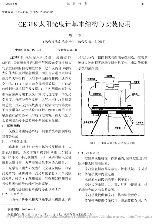
1 仪器结构仪器主体由传感系统、伺服系统和控制系统三部分构成。
1.1 传感器系统瞄准器由两只组合为一体的长圆桶组成,头部孔径相同,为光学窗口提供相同的1.5°视场角;底部大、小孔径相差10倍,分别对应天空视窗和太阳视窗,为两视窗提供不同的入射量。
光学窗口由太阳视窗和天空视窗构成,内装滤光片轮、硅探测器。
滤光片轮装有8片窄波段滤光片,提供8个观测通道;硅探测器探测的信号经数据传输线传输至控制系统。
湿度传感器在有降雨时停止仪器工作。
1.2 伺服系统由方位步进电机和天顶角步进电机组成;两只电机各有一根控制线与控制系统相连,控制系统通过控制程序驱动步进电机工作,带动传感器系统扫描探测。
图1 CE318太阳光度计结构示意图1.3 控制系统控制系统集成在一控制箱内,包括控制盒、电池块和太阳能电池板。
控制盒包括液晶显示窗、控制按键、控制模块、传输模块和内置电池。
液晶显示窗提供菜单和状态显示。
控制按键由绿、白、黄、红四个键组成,供手动指令输入和参数设置。
控制模块提供和控制扫描和测量程序。
太阳能组件测试仪使用说明书
①③⑥②④⑤安装滑道安装导轨将导轨移动到合适位置,拧紧螺丝,锁死导轨。
安装感温探头支架1.4连接线路:(串口线)(采集卡线 3米)(电路板连接方式)(设备电源线)(鳄鱼夹) (设备外接线) 打开设备内部的空气开关释放急停开关(见第6页,操作面板说明)打开钥匙开关,设备上电(见第6页,操作面板说明)点击桌面“(面板初始界面)工作状态指示,此当为工作状态时,电压工作状态指示,此(电池参数界面)注意:上图显示的“电流修正目标”与“电压修正目标”值,用于图示说明,实际参数请根改光为(软件主界面)种模式切换。
(原始曲线)2.2当前测试数据区、状态区:点击“给电容充电”后,控制面板上的电压会升到设定值,“当前充电电容状态”则会由红灯转变成绿灯。
设置生产过程中的常用选项。
3.1.1电池规格选择:选择当前的待测电池规格,点击确定后生效。
4. 数据查询介绍数据查询面板可检索指定时间的检测记录。
4.1查询条件设置:设置查询的时间范围,点击查询按钮查询,缺省查询当天4.2.2打印和导出数据即可。
5.4生产信息5.4.1生产信息:可输入操作员的名称及设备编号。
5.4.2自动产生:按照在“快速设置”里设置的“测试序列号”自动递增。
5.4.3条码产生:选择条码产生后会在主界面上显示一个条码输入的文本选中上图中的“DAQPilot”后,会出现下图所示的界面继续点击“Next”按钮,会出现下图所示的界面继续点击“Next”按钮,会出现下图所示的界面点击上图所示“Install”按钮,开始安装,安装完毕前会出现下图所示的界面点击“Finish”按钮,完成安装。
选择上图中“Driver Installation”选项后,会出现如下图所示的界选择上图中的“Win98/NT/2000/XP/Vista Driver(D2K-DASK)”选选中上图中的“Typical”选项后,然后点击上图中的“Next”,会出现点击上图中的“Install”按钮,会出现如下图所示的界面:点击上图中“Finish”按钮,会出现如下图所示的界面:点击上图中的“EXIT”按钮,退出改安装软件。
3500 65监控器数据手册:16路温度监控设备说明书
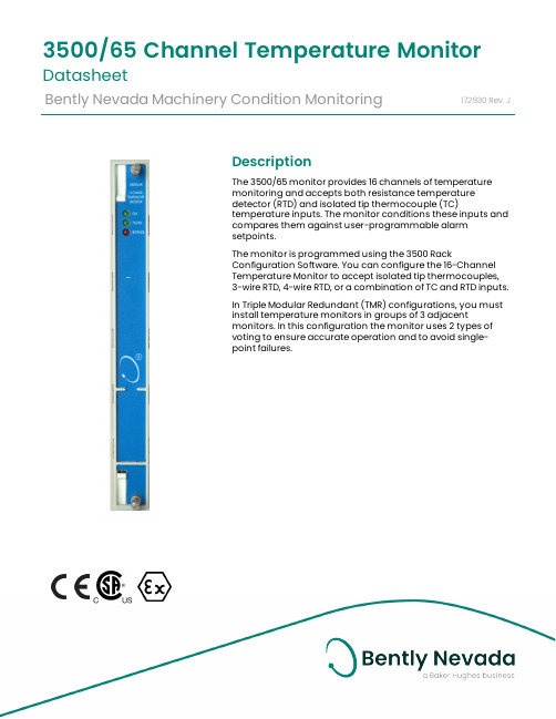
DescriptionThe 3500/65 monitor provides 16 channels of temperaturemonitoring and accepts both resistance temperaturedetector (RTD) and isolated tip thermocouple (TC)temperature inputs. T he monitor conditions these inputs andcompares them against user-programmable alarmsetpoints.The monitor is programmed using the 3500 RackConfiguration Software. Y ou can configure the 16-ChannelTemperature Monitor to accept isolated tip thermocouples,3-wire RTD, 4-wire RTD, or a combination of TC and RTD inputs.In Triple Modular Redundant (TMR) configurations, you mustinstall temperature monitors in groups of 3 adjacentmonitors. In this configuration the monitor uses 2 types ofvoting to ensure accurate operation and to avoid single-point failures.3500/65Channel Temperature Monitor DatasheetBently Nevada Machinery Condition Monitoring172930Rev.JSpecificationsInputsPower Consumption 3 watts nominal SignalAccepts from 1 to 16 RTD or isolated tip TC transducer signals.InputImpedanceGreater than 1 M Ω for each lead input.TransducersPlatinum RTDs with α = 0.00385 are the worldwide industrial standard and are the recommended RTDs for all applications.OutputsSignal ConditioningSpecified at +25°C (+77° F). Full-scale range for each channel is set in the field via 3500 Configuration Software. No calibration is requiredAlarmsAlarm Setpoints You can use software configuration to set Alert and Danger setpoints for the value measured by the monitor. Alarms are adjustable from 0 to 100% of full-scale for each measured value. The exception is when the full-scale range exceeds the range of the sensor. In this case, software will limit the setpoint to the range of the sensor. Accuracy of alarms are to within 0.13% of the desired value. The 3500/65 16-channel temperature monitor has both under- and over-alarm setpoints.Alarm Time Delays You can use software to program alarm delays as follows:Alert Delay From 1 to 60 seconds in 1-second increments.Danger Delay From 1 to 60 seconds in 0.5-second increments or set to theminimum alarm delay of 225 mS.Proportional ValuesProportional values are temperaturemeasurements used to monitor the machine.The 16-channel temperature monitor returnstemperature proportional values.Environmental LimitsOperatingTemperature:-30°C to +65°C (-22°F to+150°F)StorageTemperature:-40°C to +85°C (-40°F to+185°F)PhysicalCompliance and CertificationsFCCThis device complies with part 15 of theFCC Rules. Operation is subject to thefollowing two conditions:l This device may not cause harmfulinterference.l This device must accept anyinterference received, includinginterference that may causeundesired operation.EMCEuropean Community Directive:EMC Directive 2014/30/EUStandards:EN 61000-6-2 Immunity for Industrial EnvironmentsEN 61000-6-4 Emissions for Industrial EnvironmentsElectrical SafetyEuropean Community Directive:LV Directive 2014/35/EUStandards:EN 61010-1RoHSEuropean Community Directive:RoHS Directive 2011/65/EU MaritimeABS - Marine and Offshore ApplicationsDNV GL Rules for Classification – Ships,Offshore Units, and High Speed and Light Craft Hazardous Area Approvals For the detailed listing of country andproduct specific approvals, refer to theApprovals Quick Reference Guide(108M1756) available from . CSA/NRTL/CClass I, Zone 2: AEx/Ex nA nC ic IIC T4Gc;Class I, Zone 2: AEx/Ex ec nC ic IIC T4Gc;Class I, Division 2, Groups A, B, C,and D;T4 @ Ta= -20˚C to +65˚C (-4˚F to+149˚F)When installed p er drawing 149243or 149244.ATEX/IECExII 3 GEx nA nC ic IIC T4 GcEx ec nC ic IIC T4/T5 GcT4 @ Ta= -20˚C to +65˚C(-4˚F to +149˚F)When installed per drawing 149243or 149244.Ordering ConsiderationsIf you add the 3500/65 to an existing 3500 System your system will require the following or later firmware and software versions:*Attempting to use the 3500/65 with3500/02 or 3500/03 software mayprevent proper operation of thesoftware.You cannot use external termination blocks with internal termination I/O modules.When ordering I/O Modules with external terminations, you must order the external termination blocks and cables separately. When ordering I/O Modules for use with 4-Wire RTDs, order with Modification 179952-01. For further information, see the 3500/65 User Guide.This will result in an I/O Module Mismatchand 562 ADC Failure in the System EventList.Ordering InformationFor the detailed listing of country andproduct specific approvals, refer to theApprovals Quick Reference Guide(108M1756) available from . 3500/65-AA-BBA: I/O Module Type01RTD/Isolated Tip TC with InternalTerminations02RTD/Isolated Tip TC with ExternalTerminationsB: Agency Approval Option00None01CSA/NRTL/C02CSA/ATEXAgency Approval Option B 02 is onlyavailable with Ordering Option A 01.External Termination Block172115-01RTD/Isolated Tip TC ExternalTermination Block (Euro Styleconnectors).Cables3500/65 Transducer (XDCR) Signal to External Termination (ET) Block Cable 134544-AAAA-BBA: Cable Length0005 5 feet (1.5 metres)00077 feet (2.1 metres)001010 feet (3 metres)002525 feet (7.5 metres)005050 feet (15 metres)0100100 feet (30.5 metres)B: Assembly Instructions01Not Assembled02Assembled SparesWhen replacing an older I/O modulewith a newer one,172109-01 Rev D, 172103-01 Rev F, 172115-01 Rev E, or futurerevisions; it is necessary to upgrade thefirmware to the monitor with the latestreleased version. You must remove theI/O module before upgrading themonitor to the latest firmware. Failure todo this will result in an I/O ModuleMismatch and 562 ADC Failure in theSystem Event List.Graphs and Figures1. Status LEDs.2. 3500/65 16 Channel Temperature Monitor3. Ethernet 10BASE-T/100BASE-TX I/O Module4. Ethernet 100BASE-FX I/O ModuleFigure 1: Front and rear views of the 3500/65 16 Channel Temperature MonitorCopyright 2020 Baker Hughes Company. All rights reserved.Bently Nevada and Orbit Logo are registered trademarks of Bently Nevada, a Baker Hughes Business, in the United States and other countries. The Baker Hughes l ogo is a trademark of Baker Hughes Company. All other product and company names are trademarks of their respective holders. Use of the trademarks does not imply any affiliation with or endorsement by the respective holders.Baker Hughes provides this information on an “as is” basis for general information purposes. Baker Hughes does not make any representation as to the accuracy or completeness of the information and makes no warranties of any kind, specific, implied or oral, to the fullest extent permissible by law, including those of merchantability and fitness for a particular purpose or use. Baker Hughes hereby disclaims any and all liability for any direct, indirect, consequential or special d amages, claims for lost profits, or third party claims arising from the use of the information, whether a claim is asserted in contract, tort, or otherwise. Baker Hughes reserves the right to make changes in specifications and features shown herein, or discontinue the product described at any time without notice or obligation. Contact your Baker Hughes representative for the most current information.The information contained in this document is the property of Baker Hughes and its affiliates; and is subject to change without prior notice. It is being supplied as a service to our customers and may not be altered or its content repackaged without t he express written consent of Baker Hughes. This product or associated products may be covered by one or more patents. See /legal.1631 Bently Parkway South, Minden, Nevada USA 89423Phone: 1.775.782.3611 or 1.800.227.5514 (US only)。
日照时数传感器技术参数
5.5. 更改波特率,波特率设置数保存在保持寄存器 40H
设置数——波特率对应表:
0 1200
2
1 2400
3
4800 9600
4 19200 5 38400
命令格式:SS 06 00 40 00 NN HH LL; SS 为设备地址,如 485 总线上只有一个设备,可以用广播地址 00; NN 为新波特率设置数;HH、LL 为 CRC 校验码。 返回格式:SS 06 00 40 00 NN HH LL;SS 为设备地址,新波特率要 设备重启后才从生效。 例:改设备波特率为 1200,命令 00 06 00 40 00 00 89 CF
日照时数传感器 NHRZ16/变送器 技术手册
1. 关于太阳日照时数 日照时数是指一天内太阳直射光线照射地面的时间。以小时为单
位。
2. 日照时数传感器简介 NHRZ16 日照时数传感器采用进口传感核心,光学材料窗口,铝
合金壳体结构,配防水航插;具有结构坚固、密封性好、使用寿命长、 测量精度高、稳定性好,传输距离长、抗外界干扰能力强等特点。可 广泛用于气象、环境、农业、科研等各类太阳日照时数测量。
10. 选型表
型号 NHRZ16
量程 A
输出 信号
U P R
说明
辐射传感器 保留定义
0~2V 电压输出 脉冲输出 RS485 输出
I——电流环输出二线制接线方式
绿红 蓝黄
控制系统 二次仪表
信号输入+ -
I——电流环输出二次仪表电压采集接线方式
+- 电源
绿红 蓝黄
R——RS485 输出接线方式
控制系统 二次仪表 信号输入+ -
采样电阻 R
+- 电源
绿红 蓝黄
- 1、下载文档前请自行甄别文档内容的完整性,平台不提供额外的编辑、内容补充、找答案等附加服务。
- 2、"仅部分预览"的文档,不可在线预览部分如存在完整性等问题,可反馈申请退款(可完整预览的文档不适用该条件!)。
- 3、如文档侵犯您的权益,请联系客服反馈,我们会尽快为您处理(人工客服工作时间:9:00-18:30)。
CE318太阳光度计技术手册中国气象局监测网络司编写说明为了满足中国气象局区域本底站业务化运行的需求,同时,为观测人员了解测量原理、对仪器进行操作和维护提供指导,为研究人员开展科研工作提供参考,有关专家和有经验的业务技术人员共同编写了本材料。
本材料由中国气象科学研究院中国气象局大气成分观测与服务中心、北京市气象局和国家卫星气象中心共同组织编写。
目 录录1 概述 (1)2 系统结构及原理 (1)2.1 仪器工作原理 (1)2.1.1 大气光学厚度 (1)2.1.2 气溶胶参数 (2)2.1.3 改进Langley法 (2)2.2 仪器结构 (3)2.3 技术指标 (5)3 系统安装及操作方法 (5)3.1 系统安装 (5)3.2 操作方法 (6)3.2.1 太阳光度计的启动和关闭 (6)3.2.2 重要操作指令列表 (8)3.2.3 天空扫描测量 (12)3.2.4 自动模式测量 (13)3.3 日常检查 (14)4 系统维护与校准 (14)4.1 系统维护 (14)4.1.1 检查系统的完整性 (14)4.1.2 检测电池电压 (14)4.1.3 检测仪器的时钟 (15)4.1.4 检测机器人臂和光学头是否水平 (15)4.1.5 检测仪器的跟踪和对准器 (15)4.2 系统定标 (15)5 数据及格式 (16)6 安全及注意事项 (16)7 附录 (18)7.1 日检查表 (18)7.2 周检查表 (19)1 1 概述概述概述大气气溶胶光学厚度的测量可反映气溶胶粒子对太阳辐射的消光作用。
世界气象组织的全球大气观测网(WMO-GAW )将大气气溶胶光学厚度的观测作为基本观测项目,目的是对全球大气本底气溶胶的变化趋势进行长期观测,进而研究其对全球和局地气候变化的影响。
同时气溶胶光学厚度的地基观测结果,也是对卫星光学遥感校准的一种重要的手段。
WMO-GAW 推荐了两种通过直接测量太阳分光辐射求出气溶胶光学厚度的方法,一种方法是采用一组短波截止滤光片和直接日射表相配合进行测量,另外一种是使用太阳光度计的测量方法。
我国区域大气本底监测站所使用的CE318型太阳光度计,是法国CIMEL 公司制造的一种自动跟踪扫描的太阳光度计。
该仪器在可见近红外波段有8个光谱通道,它不仅能自动跟踪太阳作太阳直射辐射测量,而且可以进行太阳等高度角天空扫描、太阳主平面扫描和极化通道天空扫描。
CE318能自动存储测量数据,并在测量完成后传输到计算机保存,它还可以通过卫星DCP 平台远程传输数据,实现无人管理自动测量、采集和远程数据传输。
CE318测得的直射太阳辐射数据和天空扫描数据,主要用来计算大气透过率,反演气溶胶光学和其它特性,如粒度谱、相函数等。
CE318太阳光度计不仅是一种大气气溶胶环境监测仪器,也可在遥感卫星传感器辐射定标时进行大气光学参数的测量。
2 2 系统结构及原理系统结构及原理系统结构及原理2.1 2.1 仪器工作原理仪器工作原理仪器工作原理2.1.1 2.1.1 大气光学厚度大气光学厚度大气光学厚度地面测得的直射太阳辐射E (W/m 2)在特定波长上根据Bouguer 定律,有:g T m R E E )exp(20τ−⋅=− (1)其中E 0是在一个天文单位(AU )距离上的大气外界的太阳辐照度,R 是测量时刻的日地距离(AU ),m 是大气质量数,τ 为大气总的垂直光学厚度,T g 为吸收气体透过率。
若仪器输出电压V 与E 成正比,则公式(1)可写成:g T m R V V )exp(20τ−⋅=− (2)其中V 0是定标常数,在大气相对稳定条件下,进行不同太阳天顶角情况下的太阳直射辐射测量,仪器输出电压V 是m 的函数,V 0是从一系列观测值外插到m 为0时的电压值V 。
由lnV+lnR 2与m 画直线,直线的斜率就是垂直光学厚度-τ,截距就是太阳光度计在大气外界测得的电压信号V 0,这就是常说的Langley 法。
大气总的消光光学厚度τ由分子散射(Rayleigh )、气体吸收消光(如臭氧,水汽)和气溶胶散射三部分组成,g a r ττττ++= (3)其中Rayleigh 光学厚度r τ由地面气压测值计算出来,在可见近红外波段气体吸收主要是臭氧和水汽的吸收。
在没有气体吸收的通道,式(3)右边的第三项可以忽略,那么从总的光学厚度减去Rayleigh 光学厚度,气溶胶的光学厚度就计算出来。
2.1.2 2.1.2 气溶胶参数气溶胶参数气溶胶参数对于气溶胶光学厚度,假定气溶胶粒子谱分布遵循容格(Junge )分布,垂直大气柱气溶胶粒子尺度谱分布如式(4):)1()()()(+−⋅==νr z c dr r dN r n (4)其中r 是球形粒子的半径,N(r)为单位面积上气溶胶粒子总数,ν是Junge 参数,因子C(z)与高度z 有关,正比于气溶胶的浓度。
在Junge 气溶胶谱类型和气溶胶复折射指数与波长无关条件下,气溶胶光学厚度与波长的关系满足公式(5):2)(+−⋅=νλλτk a (5)式(5)中k 为Angstrom 大气浑浊度系数,是波长1µm 处大气气溶胶光学厚度。
由式(5)可知,我们可以通过测量气溶胶光学厚度的谱分布就能求出ν和k ,利用k 和ν继而可以求出其它波长上的气溶胶光学厚度。
2.1.3 2.1.3 改进改进Langley 法在地面测得的直射太阳辐射信号在940nm 附近水汽吸收带不符合Bouguer 定律,Bouguer 指数消光定律是对单色辐射而言。
依照Bruegge 和Halthore 在1992年的研究成果,水汽透过率这时用两个参数表达式来模拟:)exp(b w aw T −= (6)其中Tw 是通道上的水汽吸收透过率,w 是大气路径水汽总量,a 和b 是常数,在给定的大气条件下,它们与太阳光度计940nm 通道滤光片的波长位置、宽度和形状有关,还与大气中的温压递减率和水汽的垂直分布有关。
a 和b 由辐射传输方程模拟来确定。
为了在各种大气条件下能有效利用太阳光度计反演水汽量,有必要研究a 和b 对这些条件的灵敏度。
在940nm 水汽吸收带,太阳光度计对太阳直射辐照度的响应可表示为:w T m R V V ⋅−⋅=−)exp(20τ (7)其中τ 是Rayleigh 散射和气溶胶散射光学厚度,它们相互独立,气溶胶光学厚度通过其它通道(如870nm 和1020nm )内插得到。
斜程水汽量w=m*PW ,PW 为垂直水汽柱总量。
将(6)式代入并两边取对数,得b b PW am R V Ln m LnV ⋅−=+−)(20τ (8)在稳定和无云大气条件下,以mb 值为X 轴,以上式左边为Y 轴画直线,直线的斜率为-a PW b ,Y 截距为Ln(V 0R -2)。
这就是通常所说的改进的Langley 法。
2.2 2.2 仪器结构仪器结构仪器结构CE318型太阳光度计主要由以下部分组成:(1)仪器主体:传感器头部、扫描步进马达和机械臂;(2)控制箱:提供软件控制预定的扫描和采样指令,获取数据,内置电池;图1为已架设好的CE318。
图1 CE318太阳光度计如图2所示,仪器主体的主要部件包括:安装在机械臂顶部的方位步进马达,机械臂的一侧是天顶角步进马达,另一侧是传感器头部。
对准器安装在传感器头部,在传感器内部有两个硅探测器,分别对应于两个对准器。
两个对准器具有同样的视场角(1.2°),但是具有不同的孔径。
它们结构上是一整体,并用一个长的螺钉向下紧固,以阻止光和水浸入。
较大的孔径对准器十倍于太阳对准器,提供必要的动态范围来观测天空。
滤光片轮安装在传感器内,它安装在对准器窗口和探测器之间。
滤光片轮由八个窄波段干涉滤光片组成,其光谱通道参数见表1。
表1CE318自动跟踪扫描太阳光度计光谱通道通道号CE318标准AERONET仪器通道中心波长nm 带宽nm 中心波长nm 带宽(nm)1 1020 10 340 102 870P1 10 380 103 670 10 440 104 440 10 500 105 870P2 10 670 106 870 10 870 107 936 10 940 108 870P3 10 1020 10注:P1、P2、P3为极化通道三根电缆(一根粗电缆连接传感器头部和控制箱,另两根电源电缆分别对应于两个马达)。
仪器主体连接在一个基盘上以便仪器安装在一个水平面上。
控制箱由一个控制模块组成。
控制模块是一个四方形白色的箱子,它准确控制扫描和CE318测量程序。
它内部有一电池,仅服务于仪器的软件部分。
控制箱也储存数据并能够被查询。
外部湿度传感器连接到控制箱上,控制传感器头在下雨时中止测量,并自动将光学头部置于PARK(停止工作)状态,并使对准器向下指向基座。
以上部件与所有电缆的连接采用防雨硅树脂密封在各自的箱子内。
图2 CE318太阳光度计结构示意图2.3 2.3 技术指标技术指标技术指标(1) 由直射太阳辐照度观测推出大气透过率。
(2) 垂直气溶胶光学厚度在大气质量数为2时的精度是±0.01-0.02。
(3) 由天空辐射测量可推出的气溶胶在0.1-3 µm 范围内的尺度谱分布,它用于辐射传输计算。
(4) 从尺度谱分布可推出气溶胶相函数。
3 3 系统安装及系统安装及系统安装及操作方法操作方法操作方法3.1 3.1 系统安装系统安装系统安装(1) 电缆连接:是各部件之间的电子连接,连接电缆线到控制箱,主要包括跟踪底座两根步进电机电缆(AZ 和ZN )、外部电池电缆、传感器头部电缆、湿度传感器电缆等;(2) 配置控制测量单元:即输入日期时间和测点的经纬度见参数设置(3) 系统定位放置三脚架使太阳能板在北半球朝南,南半球朝北;架好三脚架后,调整三腿使太阳光度计底盘水平,调至水平后固定腿部; 将跟踪底座固定在一个稳定水平面上,但传感器头不要放上; 用螺丝刀将底座调平; 启动PARK 指令(指令的详细说明见下面章节);底座到达PARK 位置,按如下方法固定传感器头:瞄准器朝下(天底) 传感器头连接器靠近轴用一塑料圈或金属弹簧固定传感器头的电缆; 启动GOSUN 指令,并调整传感器头电缆的位置转动底座使瞄准器对准太阳(通过沿着垂直轴转动整个系统)再次启动PARK 指令重复GOSUN 指令,确认是否对准太阳注:在P A R K 位置,高度角旋转轴朝向地理的东西方向,传感器头在西。
头部旋转面在子午面上。
方位角定位启动PARK 指令; 把步进马达系统放到架子上,并调节使其底座水平; 导引天顶马达控制轴朝西(垂直运动); 启动GOSUN 指令; 用手水平转动马达系统底座,使对准器瞄准太阳。
当太阳的像尽可能接近对准孔,表明操作正确;使马达系统底座水平,如果必要,检查配置和修正平台的位置; 调整底座的螺钉,再次控制水平; 当所有螺丝固定之后,再检查所有前面的操作。