模糊控制 英文文献
模糊控制理论及工程应用

模糊控制理论及工程应用模糊控制理论是一种能够处理非线性和模糊问题的控制方法。
它通过建立模糊规则和使用模糊推理来实现对系统的控制。
本文将介绍模糊控制理论的基本原理,以及其在工程应用中的重要性。
一、模糊控制理论的基本原理模糊控制理论是由扬·托东(Lotfi Zadeh)于1965年提出的。
其基本原理是通过建立模糊规则,对系统的输入和输出进行模糊化处理,然后利用模糊推理来确定系统的控制策略。
模糊规则是一种类似于“如果...那么...”的表达式,用于描述输入和输出之间的关系。
模糊推理则是模糊控制系统的核心,它通过将模糊规则应用于模糊化的输入和输出,来确定控制的动作。
二、模糊控制理论的工程应用模糊控制理论在工程应用中具有广泛的应用价值。
下面将分别介绍其在机械控制和电力系统控制中的应用。
1. 机械控制模糊控制理论在机械控制领域有着重要的应用。
其优势在于能处理非线性和模糊问题,使得控制系统更加鲁棒和稳定。
例如,在机器人控制中,模糊控制可实现对复杂环境的适应性和灵活性控制,使机器人能够自主感知和决策。
此外,模糊控制还可以应用于精密仪器的控制,通过建立模糊规则和模糊推理,实现对仪器位置和姿态的精确控制。
2. 电力系统控制模糊控制理论在电力系统控制领域也有着重要的应用。
电力系统是一个复杂的非线性系统,模糊控制通过建立模糊规则和模糊推理,可以实现对电力系统的稳定性和性能进行优化。
例如,在电力系统调度中,模糊控制可以根据不同的负荷需求和发电能力,实现对发电机组的出力控制,保持电力系统的稳定运行。
此外,模糊控制还可以应用于电力系统中的故障诊断和故障恢复,通过模糊推理,快速准确地定位和修复故障。
三、总结模糊控制理论是一种处理非线性和模糊问题的有效方法。
其基本原理是通过建立模糊规则和使用模糊推理来实现对系统的控制。
模糊控制理论在机械控制和电力系统控制等工程领域有着广泛的应用。
它能够提高控制系统的鲁棒性和稳定性,并且能够适应复杂的环境和变化,具有良好的控制效果。
模糊控制的移动机器人的外文翻译.doc

1998年的IEEE国际会议上机器人及自动化Leuven ,比利时1998年5月一种实用的办法--带拖车移动机器人的反馈控制F. Lamiraux and J.P. Laumond拉斯,法国国家科学研究中心法国图卢兹{florent ,jpl}@laas.fr摘要本文提出了一种有效的方法来控制带拖车移动机器人。
轨迹跟踪和路径跟踪这两个问题已经得到解决。
接下来的问题是解决迭代轨迹跟踪。
并且把扰动考虑到路径跟踪内。
移动机器人Hilare的实验结果说明了我们方法的有效性。
1引言过去的8年,人们对非完整系统的运动控制做了大量的工作。
布洛基[2]提出了关于这种系统的一项具有挑战性的任务,配置的稳定性,证明它不能由一个简单的连续状态反馈。
作为替代办法随时间变化的反馈[10,4,11,13,14,15,18]或间断反馈[3]也随之被提出。
从[5] 移动机器人的运动控制的一项调查可以看到。
另一方面,非完整系统的轨迹跟踪不符合布洛基的条件,从而使其这一个任务更为轻松。
许多著作也已经给出了移动机器人的特殊情况的这一问题[6,7,8,12,16]。
所有这些控制律都是工作在相同的假设下:系统的演变是完全已知和没有扰动使得系统偏离其轨迹。
很少有文章在处理移动机器人的控制时考虑到扰动的运动学方程。
但是[1]提出了一种有关稳定汽车的配置,有效的矢量控制扰动领域,并且建立在迭代轨迹跟踪的基础上。
存在的障碍使得达到规定路径的任务变得更加困难,因此在执行任务的任何动作之前都需要有一个路径规划。
在本文中,我们在迭代轨迹跟踪的基础上提出了一个健全的方案,使得带拖车的机器人按照规定路径行走。
该轨迹计算由规划的议案所描述[17] ,从而避免已经提交了输入的障碍物。
在下面,我们将不会给出任何有关规划的发展,我们提及这个参考的细节。
而且,我们认为,在某一特定轨迹的执行屈服于扰动。
我们选择的这些扰动模型是非常简单,非常一般。
它存在一些共同点[1]。
模糊控制简介

න
������������ (������)������������ (������) (������, ������)
������������
模糊逻辑与近似推理
➢ 近似推理过程: 前提1(事实):������是������’ 前提2(规则):������������ ������ 是 ������,������ℎ������������ ������ 是 ������ 结论:������是������’ 这里������’和������是论域������中的模糊集合,������’和������是论域������中的模
⋯ ������������ ������2, ������������
⋱
⋮
������������ ������������, ������1 ������������ ������������, ������2 ⋯ ������������ ������������, ������������
例:������ = {子,女},������ = {父,母},模糊关系������“子女与
父母长得相似”,用模糊矩阵表示则为:
父母
������
=
子 女
0.8 0.3
0.3 0.6
模糊控制的数学基础
➢ 模糊关系合成 设������、������、������是论域, ������是������到������的一个模糊关系, ������是������到������
洗衣机模糊控制

故障等.
4) 研制样机的洗净率、各项传感特性、各种模
糊输出量、各种洗涤功能均达到了我国相关的标准
和合同约定的技术要求.
5) 经连续运转和施加强电磁干扰,证明系统
健壮性好、抗干扰能力强.
6) 实现模糊控制后,样机节水12%~18%,
节电7%~12%.节水、节电、省时效果良好.
门狗”技术等方面加强研究和实施.着重防止程序
“跑飞”,并解决好系统非法复位的自恢复问题,使系
统具有故障诊断功能.
2.4 其他技术框架
2.4.1 实验分析与模糊规则的建立 洗衣机的洗
涤过程包括初洗、主洗、过清、处理等工艺程序.洗
涤的全过程为3输入5输出的控制过程,输入量为
布质、布量、脏污程度和脏污性质;输出量为水位、转
术框架
本系统是一个多输入多输出的控制系统.主要
输入量(模糊量)有洗涤物的布质、布量、脏污程度、
脏污性质等.系统的输出量有电机转速、进水量、水
位、洗涤时间(包括过清和脱水时间)和洗涤剂投放
量等.总的设计思路是利用相应的传感器检测各种
输入量,通过转换和处理,运用各种控制模块和模糊
控制规则,经模糊计算和推理决策,确定洗涤程序和
洗涤过程中的输出量.
2.1 模糊控制器设计的框架构思
模糊控制器设计利用主要因素推理和间接推理
等方法.主要因素推理即是抓住主要因果关系,放
弃次要因果关系.例如,用布质、布量的监测数据来
推理决策水位、转速、洗涤时间等工作参数.间接推
理亦称顺序推理,即将前一种推理作为本次推理的
前提,从而引申出新的结果.例如,若洗涤剂投放量
机以更强大的生命力.系统的研制开发是以XGQ-
英文 单片机模糊逻辑控制器对永磁直流电动机的设计和应用

Engineering Applications of Artificial Intelligence 18 (2005) 881–890Single-chip fuzzy logic controller design and an application on a permanent magnet dc motorSinan PravadaliogluI.M.Y.O., Control Sys. Department, Dokuz Eylu ¨l University, Menderes cad, Istasyon sok 5, Buca, 35170 Izmir, Turkey Received 27 March 2004; accepted 11 March 2005 Available online 23 May2005AbstractThis paper describes a low-cost single-chip PI-type fuzzy logic controller design and an application on a permanent magnet dc motor drive. The presented controller application calculates the duty cycle of the PWM chopper drive and can be used to dc–dcconverters as well. The self-tuning capability makes the controller robust and all the tasks are carried out by a single chip reducing the cost of the system and so program code optimization is achieved. A simple, but effective algorithm is developed to calculate numerical values instead of linguistic rules. In this way, external memory usage is eliminated. The contribution of this paper is to present the feasibilityof a high-performance non-linear fuzzy logic controller which can be implemented byusing a general purpose microcontroller without modified fuzzy methods. The developed fuzzy logic controller was simulated in MATLAB/SIMULINK. The theoretical and experimental results indicate that the implemented fuzzy logic controller has a high performance for real-time control over a wide range of operating conditions.2005 Elsevier Ltd. All rights reserved.Keywords: Dc motor drive; Fuzzy logic controller; Microcontroller; Application; Simulation1.IntroductionIn switch-mode power supplies, the transformation of dc voltage from one level to another level is dc–dc conversion and accomplished by using dc–dc converter circuits, which offers higher efficiency than linear regulators. They have great importance in many practical electronic systems, including home appliances, computers and communication equipment. They are also widely used in industry, especially in switch-mode dc power supplies and in dc motor drive applications. The dc- dc converter accepts an unregulated dc input voltage and produces a controlled dc output at desired voltage level. They can step-up, step-down and invert the input dc voltage and transfer energy from input to output in discrete packets. The one disadvantage of dc–dc converters is noise. At every period to charge in discrete packets, it creates noise or ripple. The noise can be minimized using specific control techniques and with convenient component selection. There are well-knowncontrol techniques including pulse-width modulation (PWM) where the switch frequencyis constant and the duty cycle varies with the load.PWM technique affords high efficiency over a wide load range. In addition, because the switching frequency is fixed, the noise spectrum is relatively narrow, allowing simple low-pass filter techniques to reduce the peak-to- peak voltage ripple. For this same reason, PWM is popularwith telecom power supply applications where noise interference is of concern .The most important requirement of a control system for the dc–dc converter is to maintain the output voltage constant irrespective of variations in the dc input voltage and the load current. However, load changes affect the output transiently and cause significant deviations from the steady-state level of dc output voltage, which must be controlled to equal adesired level by the control systems. The inherent switching of a dc–dc converter results in the circuit components being connected periodically changing configurations, each configuration being described by a set of separate equations. Transient analysis and control system design for a converter is therefore difficult since a number of equations must be solved in sequence. Although the state-space averaging is the most commonly used model to obtain linear transfer functions to solve this problem, it neglects significant parts of non-linear behavior of dc–dc converters. Development of non-linear controllers for dc–dc converters have gained considerable attention in recent years.A fuzzy logic model based controller is chosen as the non-linear controller for this study. Fuzzy logic control (FLC) has been an important research topic. Despite the lack of concrete theoretical basis many successful applications on FLC were reported and various applications for dc–dc converters and electrical drives have been published and can be found in the literature (So et al., 1996, 1995;Mattavelli et al., 1997; Brandsetter and Sedlak, 1996; Hyo et al., 2001; Gupta et al., 1997;Zakharov, 1996; V as, 1998, 1999). FLC has a wide-spread application on the non-linear and complex systems as well as linear systems due to its capability to control the systems that might not have a transfer function between input and output variables. Experi-ences show that fuzzy control can yield superior results to those obtained by conventional control algorithms.In the meantime, new fuzzy microcontroller chips are available on the market and are able to execute fuzzy rules very fast with their mask programmed algorithms that have some drawbacks such as restriction in implementing any desired algorithm. Digital signal processing (DSP) integrated circuits (IC) are capable of computing and processing the system variables very quickly with high precision. But most of the DSP circuits are expensive and do not contain peripherals such as analog to digital (A/D) and digital to analog (D/A) circuits for conversion and PWM generator on chip,and need to be added externally. A fuzzy controller application among the others on dc–dc converters used a TMS320-DSP and fuzzy controller with an evaluation module plus some external chips. They were an A/D converter for feedback signal evaluation, a D/A converter for converting the calculated quantity into a control output and a PWM chip to generate the appropriate duty cycle for the semiconductor switching elements (So et al., 1995; Brandsetter and Sedlak, 1996). An implementation of an FLC with 8-bit conventional microcontroller is presented in Gupta et al. (1997) for dc–dc converters and a modified centroid method for defuzzication process is used to reduce the processing time of 8-bit microcontroller. However, this moded defuzzification technique increases the settling time of the system. A detailed simulation and experimental study on the closed-loop control of dc motor drive with FLC is carried out in Zakharov (1996) and a PC computer with an evaluation board is employed for FLC. The transient response of proportional integral (PI)-type current and speed controllers are compared to that of the FLC.The aim of the study presented in this paper is to design and to implement a high-performance fuzzy tuned PI controller for controlling the rotor speed of permanent magnet dc motor (PMDCM). We also provide a wayof designing such a controller in a cost effective way by using a general purpose single-chip microcontroller. This design is implemented with-outmaking the assumptions for the modification of defuzzification process which was presented in Guptaet al. (1997). This leads to an improved performance of the transient and steadystate of the closed-loop System.The experimental results are also compared to the simulation result obtained from MATLAB/SIMU-LINK.2.Permanent magnet dc motor and class C chopperA PMDCM fed via class C chopper can be described by the state-space form in the continuous time as follows:where R a is armature resistance (Ohm), L a is armature inductance (Henry), K aψis back electromotive force and torque constant (V/rad/s or Nm/A), J is total moment of inertia (kgm2) and B v is viscous friction constant (Nm/rad/s). V a(t)represents the voltage applied to armature by a class C type of chopper given in Fig. 1.The average value of armature voltage is a function of t on, period of chopping and the level of dc input voltage as shown in Fig. 2.In analog control systems, the repetitive sawtooth waveform is compared with the control voltage to generate the PWM gate signals to the MOSFETs employed in the chopper. The duty cycle is equal to the ratio between control voltage (E c) and the peak of sawtooth. The control voltage signal is generally obtained amplifying the difference between the actual output voltage and its desired value. Simple controls can be carried out using analog IC, such as operational amplifier circuits but sophisticated control tasks usually involves the using of digital ICs, microcontrollers or DSPs to support high-performance, repetitive, numeri-cally intensive tasks. Building a closed-loop control system, the actual output voltage can be sensed by a tacho generator which produces an output voltage proportional to armature rotation. Development and application of FLC in electrical drives have drawn greater attention in recent years (Vas, 1998, 1999).Fig. 1. Dc motor and Class C chopper.Fig. 2. V oltage waveforms of Class C type of chopper.3. Fuzzy controllerConventional controllers are derived from control theory techniques based on mathematical models of the process. They are characterized with design procedures and usually have simple structures. They yield satisfying results and are widely used in industry. However, in a number of cases, such as those, when parameter variations take place, or when disturbances are present, or when there is no simple mathematical model, fuzzy logic based control systems have shown superior performance to those obtained by conventional control algorithms.Fuzzy control is a method based on fuzzylogic. L.A.Zadeh's pioneering work in 1965, and his seminal paper in 1973 on fuzzy algorithms introduced the idea of formulating the control algorithm by logical rules. On the basis of the ideas proposed in this paper, Mamdani developed the first fuzzy control model in 1981. This then led to the industrial applications of fuzzy control.Fuzzy control can be described simplyas "control with sentences rather than equations" (Jan Jantsen1998). It provides an algorithm to convert a linguistic control strategy—based on expertknowledge—into an automatic control strategy. The essential part of a fuzzy controller is a set of linguistic rules which is called rule base.1. If error is Negative and change in error is Negative then output is Negative Big.2. If error is Negative and change in error is Zero then output is Negative Medium.The fuzzy rules are in the familiar if–then format and the "if side" is called the antecedent and the "then side"is called the consequent. The antecedents and the consequents of these if–then rules are associated with fuzzy concepts (linguistic terms), and they are often called fuzzy conditional statements. A fuzzy control rule is a fuzzy conditional statement in which the antecedent is a condition and the consequent is a control action.The fuzzy controller should execute the rules and compute a control signal depending on the measured inputs or conditions. There is no design procedure in fuzzy control such as root-locus design, pole placement design, frequencyresponse design, or stability design because the rules are often non-linear and close to the real world. Non-linearityis handled byrules, member-ship functions and the inference process.Described fuzzy logic model based on non-linear controller is developed and tested on real-time feedback control for the rotor speed of PMDCM. The speed feedback and fuzzy control algorithm block diagram are given in Fig. 3. The tacho-generator measures the actual rotor speed supplying input to the on-chip A/D converter. At the beginning of every kth switching cycle, the reference rotor speed w ref is compared with the actual rotor speed w act. The error (e(k)) and change of error (ce(k)) values of rotor speed are the inputs of the fuzzy control algorithm, which are defined asThe microcontroller calculates these inputs right after conversion from on-chip A/D converter. The fuzzy control algorithm is divided into three modules:(1) fuzzification, (2) decision-making or inference, (3)defuzzification.Fig. 3. Block diagram of drive circuit.In the fuzzification module, the error and change of error signals are evaluated by fuzzy singletons and their numerical values are converted into seven linguistic variables or subsets: PB (Positive Big), PM (Positive Medium), PS (Positive Small), ZE (Zero), NB (Negative Big), NM (Negative Medium) and NS (Negative Small). The fuzzification module calculates the degree of membership of every linguistic variable for given real values of error and change of error. The triangular shapes as given in Fig. 4a are used for smooth operation on membership functions.The calculated values of fuzzy variables are used in he decision-making process. Decision-making is infer-ing from control rules and linguistic variable defidefini-tions. There are seven sets for the error and seven sets for the change of error, and thus total 49 rules taking place for the whole control surface which are given in compact form in Table 1. This rule table can reflect experiences of the human experts.For each error and change of error, there are two overlapping memberships; therefore, all linguistic vari-ables except two has zero membership. Each two overlapping memberships of error and change of error will create four combinations as inference results.The maximum of these four inference results will have two parts, namely, the weighting factor w i and the degree of change of duty cycle y i. The min fuzzy implication rule of Mamdani is used to obtain the weighting factorwhich gives the membership degree of every relation (Lee, 1990). The inferred output ui of each rule isFig. 4. (a) Membership functions for error and change of error.(b) Enlargement for error membership function at a point x.Here, y i represents the centroid of membership function defining the ith rule output variable and can be stored in a look-up table for quick acquisition.Membership functions for change of output of FLC,which is the dutycycle for this application, is shown in Fig. 5According to the membership functions of the input,the output variables and the rule table, respectively, in Figs. 4a, 5 and Table 1, the control surface representa-tion is shown in Fig. 6.In defuzzification module, a crisp value for output is performed. Although the defuzzification process has many methods, the weighted average method is employed for this application because the operation of this method is computationally quite simple and takes less time in the computation process of microcontroller (Bart Kosko,1991; Ross, 1995). The output of defuzzification module can be represented byThe inferred output results and the weighing factors from each of the four rules are used in the equation given above to obtain a crisp value for the change of duty cycle. It is obvious that this calculation is the most time-consuming part of FLC and has computational complexity. The microcontroller output is the PWM duty cycle and defined asThis crisp value is the fuzzy controller actual output at the kth sampling period and is obtained from the previous value of control d(k-1) that is updated by Δd(k).In case of wide range changes of the drive operation, the response of FLC will be non-linear. This means that they should compensate either big positive errors like start-up or small negative errors during step changes.The main difference between the classical PI controller and fuzzy PI controller can be defined with their gains where fuzzy type has variable gain.4.Simulation resultsComputer simulation has an important role in the evaluation of power electronics and closed-loop con-troller designs (Pires and Silva, 2002). Fig. 7 shows the block diagram used in the MATLAB/SIMULINK program to simulate the closed-loop system which was performed on a PMDCM fed via class C chopper, presented in Fig. 3, having the following parameters:R a=0.271Ω,L a=0.41mH, J=0.00074 kgm2, B v=0.0013Nm/rad/s, K aψ= 0.0527V/rad/s.The simulation is performed in the time domain and the sampling period of A/D converter is T =1ms, dc input voltage V =24 and reference speed w ref=188.5 rad/s. The load torque T L was defined as a linear function of rotor speed w r having the operating point (T L =0.26Nm, w r =188.5 rad/s). KE1 in the block diagram given in Fig. 7 is the gain of tacho-generator, W ref1 and W ref , which are the step functions to change the sign of change of error in first sampling. The block of signal generator supplies 2 kHz sawtooth waveform having the magnitude of one; hence, the control signal generated bythe FLC will be equal to the duty cycle of the gate signals applied to the power switches. During simulation process when the change of error is calculated, noise on output of the A/D converter has appeared because change of error in time of 1ms is a very small value, so we have a problem of least significant bit in the number. To eliminate this effect additional gain blocks are introduced before the A/D converter block. So it is necessary to divide after A/D converter output and that is why KE and KCE are placed in the configuration.Fig. 8 shows the variation of actual rotor speed and armature current in time, when the load torque is increased by the amount of 0.17Nm at 0.4 s. The actual rotor speed deviates from the reference speed and comes back to the reference after transients are damped out. The increase of armature current is the response to increase of load torque.5.Hardware and software designsThe hardware setup for the proposed fuzzy logic algorithm was implemented in assembly programming, using 8-bit RISC (Reduced Instruction Set Computing) core microcontroller AT90S8535. A schematic diagram of the FLC with one of the Insulated Gate Bipolar Transistor (IGBT) drive circuits of Class C chopper is shown in Fig. 9. The microcontroller has 8K bytes of programmable flash memory, 512 bytes of internal random access memory, 8 channel 10 bit ADC, 10 bit PWM output, 16 different interrupt sources, an analog comparator, 32 programmable I/O lines, a bi-directional serial interface and has the ability to execute assembler instructions in a single clock cycle. The processing speed is one million instructions per megahertz crystal (Atmel Corporation).The universe of discourse for error and change of error are extended from -1024 to +1024 and the grades of each membership function (0–1) are also extended from 0 to 1024. In order to classify the fuzzy controller inputs, e(k) and ce(k), into seven fuzzy sets and to determine their memberships, 10 bit mathematical routines are used. Therefore, processing the on-chip 10 bit A/D converter sampling values and setting up the on-chip 10 bit PWM output for semiconductor switches are directlyachieved. As a result, the total system resolution is extended to 1/1024 insteadof 1/256 and better performance is obtained.The symmetrical and 50% overlapped triangular membership functions of e(k) and ce(k) simplify the calculations and its negative side is a reflection of the positive. The fuzzy subset linguistic rule table given in Table 1 is changed to integer numbers in order to suit assembly programming. A simple but effective algo-rithm is designed for the appropriate numerical values ofconverted linguistic rules. This is realized with the following equation according to calculated error values.The most important difference between the present paper and the papers cited in the references, is the developed algorithm for fast calculation.For error membership function,where e is the error value, X min=-1024 is the minimum value of the control variable as shown in Fig. 4a, s is the section number, starting from 0 to 6 for representing seven fuzzy subsets of errormembership and T g the width of every triangular membership function, here it is 256.For instance, let w ref =1000 rpm and w act =650 rpm. The calculation of error according to Eq. (2) is e(k)=350 rpm at a point x shown in Fig. 4b and from Eq. (8),is calculated. This value should be classified into fifth fuzzy set. It is well known that every e(k) belongs to at most two fuzzy sets. Therefore, the above error value has two overlapping fuzzy sets, fifth and sixth which are prevailed to linguistic PS and PM as shown in Fig. 4b. The fraction part of s always belongs to the membership function which has a positive slope. Therefore, for this example, the membership grade at point b shown in Fig.4b isμpm(e)=0.36719.The sum of membership grades of two symmetrical and 50% overlapped triangular fuzzy sets is always equal to 1.0μpm(e)+μps(e)=1.0.Hence the membership grade at point a isμps(e)=1.0-0.36719=0.63281.At the kth sampling time, change of error membership function is also evaluated using the same Eq. (8). The calculated values of fuzzy variables are used in the decision-making process. The flow chart of implemented assembler program is shown in Fig. 10.Membership functions of the output duty cycle for application on a PMDCM drive is presented in Fig. 5.A table is created for defuzzification process and stored as a look-up table containing the mean values of these membership functions of output and are used according to the weighted average method for defuzzification. The weighted average method for the defuzzification has an advantage over the other techniques in the case of limited memory structure of RISC core microcontrol-lers. A crisp value for the change of duty cycle is calculated from Eq. (6). According to Eq. (7) and the change of output of FLC shown in Fig. 5, the calculated change of the duty cycle is used to determine the new duty cycle for the application,The calculated value is used to update the PWM output by an interrupt routine shown in Fig. 10 at every 1ms (milli-second). Tests have shown that realization of the mentioned fuzzy interrupt routine lasts 450 ms (micro-second) processing time with 4MHz clock frequency. In this implementation, a D/A converter,which might be needed for output variable is eliminated by directly controlling the on–off periods of semicon-ductor switches via the on-chip PWM generator. When the motor is started from standstill, the error and change of error are estimated as positive at first sampling of rotor speed since their initial value at standstill are taken to be zero. The trend of change of error from standstill to steady state of rotor speed is negative; therefore, by changing the sign of change of error from positive estimated at first sampling to negative reduces the settling time of the rotor speed.6.ResultsAnother identical machine was coupled to the motor via their shafts and operated as a generator for loading. Two different loading conditions were applied on the motor. In the first loading condition, the generator terminals were closed to the resistive load of 2Ωand, the rotor speed and armature current variations in time during this loading case were recorded. These results are given in Fig. 11a (Upper trace: 1V/div., Lower trace: 0.2V/div. and 100mV/A. Time base: 200ms/div.). In the second loading condition, the resistance of 2Ωwas connected to the generator terminals while the rotor is running at reference speed. After the transients were damped out, the resistor was disconnected. The varia-tions of actual rotor speed and generator output current during this case were recorded and are given in Fig. 11b (Upper trace: 1V/div., Lower trace: 0.2V/div. And 100mV/A, Time base: 500ms/div.). It can be observed from the waveforms that the fuzzy logic controller responds to the step change on the load properly and brings the actual rotor speed back to the reference speed.7.ConclusionFuzzy logic controller is implemented without mod-ified methods byusing a general purpose low-cost microcontroller for the speed control of a PMDCM. All the tasks are carried out bya single chip reducing the cost of the system and program code optimization is achieved with developed effective algorithm. In our approach, the software-based decision table is used and only simple computations required in the on-line control of an FLC; therefore, higher sampling rate can be realized more easily when comparing with other type of control schemes. The developed fuzzy logic controller was simulated in MA TLAB/SIMULINK. Simulation and experimental results are compared in order to show the response of the FLC under loading conditions. It can be found that the experimental results are very close to the simulation results. The rise and settling times are reasonably smaller and there is no significant overshoot on the experimental results. The effect of saturation is not included into the motor and generator models; therefore, the simulation results deviate from the experimental results within a small percentage during loading transients. The experiments indicate that the implemented fuzzy controller has a high performance for real time control over a wide range of operating conditions.ReferencesAtmel Corporation. . A VR RISC datasheets, application notes, tools.Bart Kosko, 1991. Neural Networks and FuzzySystems. Prentice-Hall, New York. Brandsetter, P., Sedlak, P., 1996. Fuzzycontrol of electric drive using DSP, PEMC’96, Budapest, Hungary, pp. 3/462–3/466.Gupta, T., Boudreaux, R.R., Nelms, R.M., Hung, J.Y., 1997. Implementation of a fuzzycontroller for DC–DC converter using an inexpensive 8-b Microcontroller. IEEE Transactions on Industrial Electronics 44 (5).Hyo, S.Park, Hee, J.Kim., 2001. Simultaneous control of buck and boost DC–DC converter byfuzzycontroller. ISIE 2001 Proceed-ings, Pusan, Korea, pp. 1021–1025.Jan Jantsen, 1998. Design of FuzzyControllers, Technical Uni-versityof Denmark, Department of Automation, Pub. No: 98-E-864.Lee, C.C., 1990. Fuzzylogic in control systems: fuzzylogic controller.Part I, II. IEEE Transactions on Systems Man and Cybernetics 20(2), 404–435.Mattavelli, P., Rossetto, L., Spiazzi, G., Tenti, P., 1997. General purpose fuzzycontroller for DC–DC converters. IEEE Transac-tions on Power Electronics 12 (1).Pires, V.F., Silva, J.F.A., 2002. Teaching nonlinear modeling, simulation, and control of electronic power converters using.MA TLAB/SIMULINK. IEEE Transactions on Education 45 (3).Ross, T.J., 1995. FuzzyLogic with Engineering Applications.McGraw-Hill, New York.So, W.C., Tse, C.K., Lee, Y.S., 1995. An experimental fuzzy controller for DC–DC converters. IEEE Power Electronics Specialist Con-ference Record. pp. 1339–1345.So, W.C., Tse, C.K., Lee, Y.S., 1996. Development of a fuzzy logiccontroller for DC/DC converters: design, computer simulation and experimental evaluation. IEEE Transactions on Power Electronics11, 1.Vas, P., 1998. Sensorless Vector and Direct Torque Control. Oxford University Press, Oxford. Vas, P., 1999. Artificial Intelligence Based Electrical Machines and Drives. Oxford UniversityPress, New York.Zakharov, A., 1996. Investigation of dc servo drive with fuzzy logic control. M.Sc. Thesis, Technical Universityof Budapest, Depart-ment of Electrical Machines and Drives.。
智能控制 模糊控制论文

华北电力大学科技学院智能控制论文模糊控制的概述及模糊控制的应用姓名:班级:学号:日期:模糊控制的概述及模糊控制在污水处理中的应用摘要:模糊控制技术对工业自动化的进程有着极大地推动作用,本文简要讲述了模糊控制的定义、特点、原理和应用,简介模糊控制在污水处理中的应用。
并讲诉了模糊控制的发展。
关键词:模糊控制;污水处理。
An overview of the fuzzy control and fuzzy control in application ofwastewater treatmentAbstract:Fuzzy control of industrial process automation has greatly promoted the role, the paper briefly describes the definition of fuzzy control, characteristics, principles and applications, Introduction to fuzzy control in wastewater treatment applications. And complaints about the development of fuzzy control.Keywords: fuzzy control; sewage treatment.1 引言传统的自动控制控制器的综合设计都要建立在被控对象准确的数学模型(即传递函数模型或状态空间模型)的基础上,但是在实际中,很多系统的影响因素很多,油气混合过程、缸内燃烧过程等) ,很难找出精确的数学模型。
这种情况下,模糊控制的诞生就显得意义重大。
因为模糊控制不用建立数学模型不需要预先知道过程精确的数学模型。
2 概述刘金琨在《智能控制》教材里提到模糊控制的定义和特点:2.1定义:从广义上,可将模糊控制定义为:“以模糊集合理论、模糊语言变量及模糊推理为基础的一类控制方法”,或定义为:“采用模糊集合理论和模糊逻辑,并同传统的控制理论相结合,模拟人的思维方式,对难以建立数学模型的对象实施所谓一种控制方法”。
文献翻译-单容水箱液位模糊控制系统设计
英文翻译系别自动化系专业自动化班级学生姓名学号指导教师Single tank water level fuzzy control system designIn industrial process control, the amount usually charged with the following four kinds, namely, level, pressure, flow and temperature. Where in the liquid is not only common in industrial process parameters, and for direct observation, easy to measure. Level control is a common industrial process control, impact on production can not be ignored. For level control system, although the conventional PID control parameters fixed, it is difficult to ensure the control parameters of the system to adapt to changes and changes in working conditions, it is difficult to get the desired effect; fuzzy control parameters have not sensitive and robust and strong features . Single-tank liquid level control system with linearity, hysteresis, coupling characteristics, this paper for the study of the level system, the application of fuzzy control theory to control research.Single tank water system structureTank level control system consists of a single tank water system ontology and AD / DA data acquisition card and other components, allows the computer to set the level value by controlling the regulator, at the entrance of a regulator valve to control and maintain the water level does not change; valve at the outlet of the receiver D-A converter output signal directly controlled tank. Valves on the inlet and discharge control rely on typical self-balancing system.Fuzzy ControlFuzzy logic control referred to fuzzy control, based on fuzzy set theory, fuzzy linguistic variables and fuzzy logic of a computer-based digital control technology. In 1965, the United States LAZadeh founded the fuzzy set theory; 1973 he gives definitions and theorems related to fuzzy logic control. In 1974, the British EHMamdani first statement in accordance with the composition of fuzzy control fuzzy controller, and apply it to the control of boilers and steam engines, get the lab's success. This pioneering work marked the birth of fuzzy control theory.Birth control is fuzzy and the development of social science and technology and the need inseparable. With the rapid development of science and technology in all areas of the automatic control system to control the precision required response speed, system stability and the ability to adapt to increasingly high, the studied systems are increasingly complex. However, due to a number of reasons, such as the charged object or process nonlinear, time-varying, multi-parameter strong coupling between the larger random noise, the intricate mechanism of the process, a variety of uncertainties and imperfect means of in situ measurements, difficult to establish the mathematical model of controlled object. While conventional adaptive control techniques can solve some problems, but the scope is limited. Good manual control for complex effects that are difficult to establish the mathematical model of the controlled object, using the traditional control methods, including methods of modern control theory based control is often better than a practical experience of operating personnel carried out. Because one of the important features of the human brain is the ability to identify and fuzzy things, judgment, fuzzy means can often seem imprecise achieve precise purpose.Contains five main parts, namely: the definition of variables , fuzzy , knowledge , logic and anti- blur . Define a variable that is the situation and determine the procedures to be observed considering control actions, such as the general control problem , the input variables and output error E output error rate of change EC, and fuzzy control variables as inputs U will control the next state . Wherein E, EC, U collectively referred to as fuzzy variables . Fuzzy input value to an appropriate ratio value domain conversion , using colloquial process variables to describe the physical quantity measured , to find the value of the membership degree according to the relative value of the appropriate language , the colloquial variable called fuzzy subset . Including database and rule base knowledge of two parts, one related to the definition of fuzzy database provides data processing ; while the rule base is controlled by agroup of language rules describe the control objectives and strategies. Imitating fuzzy logic judgment under the concept of human beings, the use of fuzzy logic and fuzzy inference inference method to obtain fuzzy control signals. This part is the essence of the fuzzy controller . Defuzzification : Convert fuzzy inference value obtained for the explicit control signals as input value system.Fuzzy controller designFuzzy controller input and error rate of change of the error, the error e = r-y, the rate of change of error ec = de / dt, where, r and y are respectively the level setpoint and measured value. The exact value of the error and error rate of change in the amount of blur blur becomes E and EC, the further you can get E and EC fuzzy language collections. E and EC by the vague language subsets and fuzzy relationship matrix, decision-making based on fuzzy inference rules synthesis, controlled amount of U, the U de vague, converted to the exact amount u, the D-A converter control valve actuators generate action.Fuzzy controller, the input signal quantization error e is 8 level (NB, NM, NS, NO, O, PS, PM, PB); the rate of change of error ec and the output variable u is 7 quantization level (NB , NM, NS, O, PS, PM, PB); error e, and the error rate of change of the output variable u ec domain of [-6,6]. The error e, error change rate ec and output variables membership functions chosen triangular membership functions. Fuzzy control rules are based on fuzzy reasoning, in the design of fuzzy control rules, you should consider the completeness of the control rules, cross and consistency, should ensure that for any given input has a corresponding control rules work. If the error is negative big change, but also for the negative rate of change of the error is large, it is necessary to adjust the control amount being small, in order to ensure the expected systematic development. On the basis of summing up experiences and basic professional knowledge, get control rules (see Table 1), designed a total of 49 (7 × 7) of the Rules.ece NB NM NS O PS PM PB NB PS PS PS PS PM PB PB NM NS PS PS PS PM PM PB NS NM NS O O PS PM PM O NB NM NS O PS PM PM PS NB NM NS O O PS PM PM NB NB NM NS NS PS PS PB NB NB NM NS NS NS NSCommonly used methods of reasoning fuzzy control system CRI reasoning table method, CRI reasoning analytical method, Mamdani inference method and the consequent direct function method. This selection is a direct Mamdani inference method, first find the fuzzy relation R, then the amount calculated according to the input control and clarity. This selection of 49 (7 × 7) of control rules, the fuzzy rule table of conditional statements can be described, for example, if e = NB and ec = NB then u = PS. Corresponding fuzzy relationship: R1 = A1 × B1 × C1, where, A1 is a fuzzy set of E, B1 is a fuzzy set of EC, C1 is a fuzzy set of U; fuzzy matrix R can be integrated according to R.Fuzzy control, simplify the complexity of system design, especially for nonlinear, time-varying lag model does not fully control systems; does not depend on accurate mathematical model of the controlled object; take advantage of the system control law to describe the relationship between variables; no value but with fuzzy variables to describe the language type system, the fuzzy controller does not have to establish a complete mathematical model of the controlled object; fuzzy controller is an easy to control and master the ideal nonlinear controller has better robustness, flexibility, robustness and better fault tolerance.单容水箱液位模糊控制系统设计在工业过程控制中,被控量通常有以下4种,即液位、压力、流量和温度。
第3章 模糊理论

3 A(1.60)= =0.3 10
……
1 A(1.77)= =0.1 10 10 0.1 0.3 0.6 1 0.5 0.1 FA = + + + + + 1.56 1.60 1.64 1.69 1.73 1.77
A(1.64)=
6 =0.6 10
模糊统计法的特点: ①随着n的增大,隶属频率会趋向稳定,这个 稳定值就是v0对A的隶属度。 ②计算量大。 2、例证法 :从有限个隶属度值,来估计U上的模糊 集A 的隶属度函数。 3、专家经验法:根据专家的经验对每一现象产生 的各种结果的可能性程度,来决定其隶属度函数。 4、二元对比排序法:通过对多个事物之间的两两 对比,来确定某种特征下的顺序,由此来决定这些 事物对该特征的隶属函数的大体形状。
二、模糊控制的特点 1、无需知道被控对象的数学模型 2、是一种反映人类智慧思维的智能控制 模糊控制采用人类思维中的模糊量,如“高”、 “中”、“低”等,且控制量由模糊推理导出 3、易于被人们所接受(核心:控制规则) 4、构造容易 5、鲁棒性好
第二节 模糊集合论基础
一、模糊集的概念
集合:具有某种特定属性的对象全体。 集合中的个体通常用小写英文字母如:u表 示; 集合的全体又称为论域。通常用大写英文字 母如:U表示。 uU表示元素(个体)u在集合论域(全体) U内。
附近隶属函数的范围
重叠鲁棒性=
U
L
( A1 A2 )dx 2(U L)
重叠指数的定义
(0.3~0.7为宜)
求重叠率和重叠鲁棒性
例:
A1
A2
重叠率= 10 / 30 0.333
0 .5 10 重叠鲁棒性= 0.5 2(40 30) 20
(2015大学论文)模糊技术在plc控制中的应用
第28卷第4期2011年4月机 电 工 程Journa l ofM echanica l&E lectr i ca l Eng i neeringV o.l 28N o .4A pr .2011收稿日期:2010-11-04基金项目:国家自然科学基金资助项目(50805042);浙江省自然科学基金资助项目(Y 10808055)作者简介:胡小平(1970-),女,浙江温州人,博士,教授,硕士生导师,主要从事企业信息集成、协同设计和知识工程方面的研究.E-m ai:l x i aop -i ng .hu @hdu .edu .cn模糊技术在PLC 控制中的应用*胡小平,朱 朋,纪华伟(杭州电子科技大学机械工程学院,浙江杭州310018)摘要:针对控制系统装置的对象往往出现大时滞、非线性和难以建立精确数学模型等问题,提出将先进的模糊控制技术引入传统的自动化装置之中。
模糊控制具有鲁棒性强等特点,可以使外界干扰和参数变化跳动对控制效果的影响大大减弱。
从工程角度出发,采用西门子PLC 常规输入/输出模块组成模糊控制器的核心,提出了相应可行的模糊控制算法,并采用了在线线性查询方式和模块化编程。
研究结果表明:在珩磨控制系统模型应用中,该模糊控制方法稳态误差小、响应速度快。
关键词:模糊控制;可编程控制器;在线线性查询中图分类号:TH39;TP271+.4 文献标志码:A文章编号:1001-4551(2011)04-0440-04Application of fuzzy technology i n the PLC controlHU X iao -pi ng ,ZHU P eng ,JIH ua -wei(Co llege ofM echan ica lEng i n eeri n g ,H angzhou D i a nziUniversity ,H angzhou 310018,Ch i n a)Ab stract :A i m ing at t he ob j ectsw hich often have severe delays ,are nonli nea r and d ifficu lt to establis h accurate m a t he m aticalm ode ls i n con -tro l syste m,the fuzzy control techno l ogy w as i ntroduced and appli ed i nto trad iti onal auto m anua l dev i ces .T he fuzzy contro l is robust ,and itcan greatl y reduce t he effect o f outsi de i nterference and beating para m eters .F ro m an eng i neer i ng view ,t he conventi onal i nput/output mod -ules o f S i em ens PLC w ere used to m ake up the fuzzy contro ll e r p s co re ,a co rresponding feasi ble f uzzy contro l algorith m was presented and t he onli ne m ethods o f li near i nquery and modu lar prog ra mm i ng were used .The results i nd i cate t hat e rror i s s ma ll and the response i s fast in ho -ni ng contro l sy stem m ode,l wh i ch i s used th i s contro lm ethod .K ey w ords :fuzzy contro;l progra mmable l og ic contro ller(PLC);onli ne li near i nquery0 引 言模糊控制是指在控制方法上应用模糊集合论、模糊语言变量和模糊逻辑推理,通过模拟人脑思维,对一些无法建立数学模型的过程进行控制的一种智能控制技术[1]。
文献检索案例格式
9.2.8 交通运输类案例【案例】检索“城际高速磁浮列车的紧急制动控制及其应用研究”的资料(资料提供:西南交通大学)【课题英文题名】study on emergency braking control in high-speed intercity maglev train and its application【题解】1.分析课题:本课题的学科分类主要属于交通动输中的列车制动装置()方面,涉及的知识学科门类比较专指,可以采用“分类号”结合其他限定性关键词的方式进行检索。
该课题属自然科学领域一般层次的应用型研究,通常情况下需要首先检索时间跨度为5年左右的文献,再视具体情况回溯5~10年。
信息类型涉及中外文专利、期刊、学位论文、会议文献等。
2. 检索工具的选择:根据检索课题的学科范围和研究的方向性质,确定需要查找的检索工具如下:1)维普中文科技期刊数据库2)万方中国科技文献数据库群3)万方中国科学技术成果数据库4)万方中国学术会议论文数据库5)万方中国学位论文数据库6)CNKI中国优秀博硕士学位论文全文数据库7)CNKI中国重要会议论文集全文数据库8)CNKI中国期刊全文数据库9)NSTL 中文库:中文期刊中文会议论文中文学位论文西文库:西文期刊外文会议论文外文学位论文国外科技报告10)EBSCO Host11)AIP/APS(美国物理所/物理协会)数据库12)CSA(剑桥科学文摘数据库)1113)Engineering Village 2(EI)14)中国国家知识产权局专利检索15)欧洲专利局16)美国专利商标局3.确定检索途径本课题最好选用主题(关键词)途径,必要时可结合分类途径,检索方法选用交替法,即时间法与引文法交替进行。
4.确定检索词首选检索词:本课题可以选用的关键词有:城际铁路(intercity railroad);高速列车(high-speed train);高速铁路(high-speed railway);磁浮(maglev、magnetic levitation);紧急制动(emergency braking);制动控制(braking control);涡流制动(Eddy-current brake)。
模糊理论综述

模糊理论综述摘要:对模糊理论进行了综述,介绍模糊控制理论及发展、研究、应用情况。
分析模糊控制的特点,指出模糊控制应用中需要解决的问题。
由于模糊控制技术是当今较先进的控制技术,因此具有广阔的应用前景。
关键词:模糊理论;模糊控制;模糊推理;模糊逻辑;模糊语言Fuzzy Theory ReviewAbstract:Fuzzy theory are reviewed, and the introduction of fuzzy control theory development, research and application. Analysis of the characteristics of fuzzy control, fuzzy control applications need to point out problems. Since fuzzy control technology is today's more advanced control technology, so it has broad application prospects.Keywords:Fuzzy theory; fuzzy control; fuzzy reasoning; fuzzy logic; fuzzy language模糊理论是在美国加州大学伯克利分校电气工程系的L.A.zadeh 教授于1965 年创立的模糊集合理论的数学基础上发展起来的,主要包括模糊集合理论、模糊逻辑、模糊推理和模糊控制等方面内容。
基于模糊集合论形成了一门新学科———模糊系统理论,近年来,模糊系统理论的研究受到了广泛重视,特别是在东方世界中,吸引了众多专家学者的关注,至今其理论研究与工程应用发展相当迅速,目前模糊控制已经作为智能控制的一个重要分支,发展成为具有一定系统理论及大量实际应用背景的一个新的研究领域。
进入20 世纪90 年代,日本的电器控制技术相当多地引进了模糊技术,使得本来就相当先进的制造技术又增添了潜在的市场竞争力。
模糊控制简介

R=(NBe × PBu ) + ( NSe × PSu ) + (0e × 0u ) + ( PSe × NSu ) + ( PBe × NSu )
NBe × PBu = (1, 0.5, 0, 0, 0, 0, 0) × (0, 0, 0, 0, 0, 0.5,1) NSe × PSu = (0, 0.5,1, 0, 0, 0, 0) × (0, 0, 0, 0,1, 0.5, 0) 0e × 0u = (0, 0, 0.5,1, 0.5, 0, 0) × (0, 0, 0.5,1, 0.5, 0, 0) PSe × NSu = (0, 0, 0, 0,1, 0.5, 0) × (0, 0.5,1, 0, 0, 0, 0) PBe × NSu = (0, 0, 0, 0, 0, 0.5,1) × (1, 0.5, 0, 0, 0, 0, 0) 0 0 0 0 0.5 1 0 0 0 0 0 0.5 0.5 0.5 0 0 0.5 0.5 1 0 0 R= 0 0 0.5 1 0.5 0 0 0 0.5 1 0.5 0.5 0 0 0 0 0 0.5 0.5 0.5 0 1 0.5 0 0 0 0 0
学习功能
数据存储 单元
y
∗ k
e
r + —
∆
∆
k
e
e
k
c
2
e
k
Байду номын сангаас
r
模糊 控制 规则
k
∆
u
u
u
u
k −1
k
+ +
被 控 对 象
y
k
六.思考
矛盾对立统一规律: 矛盾对立统一规律:两面性 • 优点:模糊逻辑本身提供了由专家构造语 优点: 言信息并将其转化为控制策略的一种系统 的推理方法, 的推理方法,因而能够解决许多复杂而无 法建立精确数学模型系统的控制问题, 法建立精确数学模型系统的控制问题,所 以它是处理推理系统和控制系统中不精确 和不确定性的一种有效方法。从广义上讲, 和不确定性的一种有效方法。从广义上讲, 模糊控制是适于模糊推理, 模糊控制是适于模糊推理,模仿人的思维 方式, 方式,对难以建立精确数学模型的对象实 施的一种控制策略。 施的一种控制策略。它是模糊数学同控制 理论相结合的产物, 理论相结合的产物,同时也是智能控制的 重要组成部分。 重要组成部分。
模糊控制相关英语
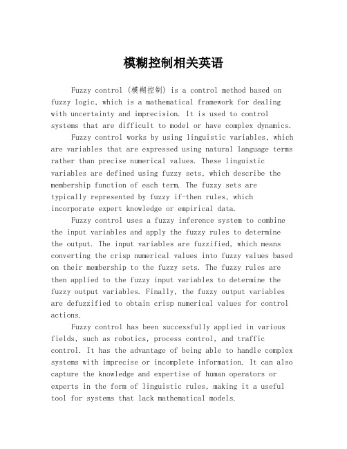
模糊控制相关英语Fuzzy control (模糊控制) is a control method based on fuzzy logic, which is a mathematical framework for dealing with uncertainty and imprecision. It is used to control systems that are difficult to model or have complex dynamics.Fuzzy control works by using linguistic variables, which are variables that are expressed using natural language terms rather than precise numerical values. These linguistic variables are defined using fuzzy sets, which describe the membership function of each term. The fuzzy sets aretypically represented by fuzzy if-then rules, which incorporate expert knowledge or empirical data.Fuzzy control uses a fuzzy inference system to combine the input variables and apply the fuzzy rules to determine the output. The input variables are fuzzified, which means converting the crisp numerical values into fuzzy values based on their membership to the fuzzy sets. The fuzzy rules are then applied to the fuzzy input variables to determine the fuzzy output variables. Finally, the fuzzy output variables are defuzzified to obtain crisp numerical values for control actions.Fuzzy control has been successfully applied in various fields, such as robotics, process control, and traffic control. It has the advantage of being able to handle complex systems with imprecise or incomplete information. It can also capture the knowledge and expertise of human operators or experts in the form of linguistic rules, making it a useful tool for systems that lack mathematical models.In summary, fuzzy control is a control method based on fuzzy logic that allows for the control of systems with uncertain or imprecise information. It uses linguistic variables, fuzzy sets, and fuzzy rules to determine control actions.。
模糊控制理论
模糊控制理论的发展与综述摘要:主要总结了模糊控制理论的形成,以及现在的发展,模糊控制理论的研究现状,模糊控制系统的应用的发展前景。
关键词:模糊控制;模糊控制理论;模糊控制系统;模糊控制理论的发展1 引言自从美国加利福尼亚大学控制论专家L.A.Zadeh教授在1965年提出的《Fuzzy Set》开创了模糊数学的历,吸引了众多的学者对其进行研究,使其理论和方法日益完善,并且广泛的应用于自然科学和社会科学的各个领域,尤其是第五代计算机的研制和知识工程开发等领域占有特殊重要的地。
把模糊逻辑应用于控制领域则始于1973。
1974年英国的E.H.Mamdani成功地将模糊控制应用于锅炉和蒸汽机的控制。
此后20年来,模糊控制不断发展并在许多领域中得到成功应用。
由于模糊逻辑本身提供了由专家构造语言信息并将其转化为控制策略的一种体系理论方法,因而能够解决许多复杂而无法建立精确数学模型系统的控制问题,所以它是处理推理系统和控制系统中不精确和不确定性的一种有效方法。
从广义上讲,模糊控制是基于模糊推理,模仿人的思维方式,对难以建立精确数学模型的对象实施的一种控制策略。
它是模糊数学同控制理论相结合的产物,同时也是只能控制的重要组成部分。
模糊控制的突出特点在于:1)控制系统的设计不要求知道被控对象的精确数学模型,只需要提供现场操作人员的经验知识及操作数据。
2)控制系统的鲁棒性强,适用于解决常规控制难以解决的非线性、时变及大滞后等问题。
3)以语言变量代替常规的数学变量,易于形成专家的“知识”。
4)控制系统采用“不精确推理”。
推理过程模仿人的思维过程。
由于介入了人的经验,因而能够处理复杂甚至“病态”系统。
传统的控制理论(包括经典控制理论和现代控制理论)是利用受控对象的数学模型(即传递函数模型或状态空间模型)对系统进行定量分析,而后设计控制策略。
这种方法由于其本质的不溶性,当系统变得复杂时,难以对其工作特性进行精确描述。
而且,这样的数学模型结构也不利于表达和处理有关受控对象的一些不确定信息,更不利于人的经验、知识、技巧和直觉推理,所以难以对复杂系统进行有效地控制。
游泳池水温控制系统
第1章绪论游泳池温度及其液位报警控制,在游泳池控制中占有非常重要的地位。
将模糊控制方法运用到温度控制系统中,可以克服温度控制系统中存在的严重滞后现象,同时在提高采样频率的基础上可以很大程度的提高控制效果和控制精度。
1.1 课题背景模糊逻辑控制(Fuzzy Logic Control)简称模糊控制(Fuzzy Control),是以模糊集合论、模糊语言变量和模糊逻辑推理为基础的一种计算机数字控制技术。
1965年,美国的L.A.Zadeh创立了模糊集合论;1973年他给出了模糊逻辑控制的定义和相关的定理。
1974年,英国的E.H.Mamdani首先用模糊控制语句组成模糊控制器,并把它应用于锅炉和蒸汽机的控制,在实验室获得成功。
这一开拓性的工作标志着模糊控制论的诞生。
传统的自动控制,包括经典理论和现代控制理论中有一个共同的特点,即控制器的综合设计都要建立在被控对象准确的数学模型(如微分方程、传递函数或状态方程)的基础上,但是在实际工业生产中,影响系统的因素很多,十分复杂。
建立精确的数学模型特别困难,甚至是不可能的。
这种情况下,模糊控制的诞生就显得意义重大,模糊控制不用建立精确的数学模型,根据实际系统的输入输出的结果数据,参考现场操作人员的运行经验,就可对系统进行实时控制,并能取得良好的控制效果。
模糊控制实质上是一种非线性控制,从属于智能控制的范畴,模糊控制的一大特点是既具有系统化的理论,又有着大量实际应用背景。
模糊控制的发展最初在西方遇到了较大的阻力,然而在东方尤其是在日本,却得到了迅速而广泛的推广应用。
近20多年来,模糊控制不论从理论上还是技术上都有了长足的进步,成为自动控制领域中一个非常活跃而又硕果累累的分支。
其典型应用的例子涉及生产和生活的许多方面[1] [2]。
水温控制在游泳池控制中是最为重要的,单水温控制过程中存在着很大的时滞性和很强的干扰。
采用一般的控制方法如PID控制,都不能很好地满足要求。
从顺应英语新闻中模糊限制语语用功能论文
从顺应论分析英语新闻中模糊限制语的语用功能【摘要】本文拟在收集权威新闻网站英语新闻报道的基础上,主要运用定性和描述分析的方法,从verschueren的顺应性理论视角出发,对不同主题的新闻报道中的模糊限制语进行语用分析和研究,指出英语新闻中模糊限制语的使用是对语言语境、物理世界、社交语境、读者的阅读心理和记者的自我保护心理的顺应。
模糊限制语的运用能起到使新闻更客观准确及时、使新闻语言的更可信、避免绝对化、及保护新闻工作者免于承担不必要的责任的作用。
【关键词】顺应论;语用功能;模糊限制语;英语新闻the analysis of the pragmatic function of hedges in english news with adaptation theoryzhang fengdepartment of journals, binzhou medical university, binzhou,256603【abstract】from the perspective of verschueren adaptation theory,analyzes and studies the pragmatic function of hedges in different news reports with qualitative and descriptive methods on the basis of the collection of news reports on authoritative news websites.the use of hedges in english news is the adaptation to the physical world,social world,and mental world of readers and reporters.with the use of hedges, news reports can be more objective,accurate,and timely,andmore convincing,can avoid absoluteness and can protect reporters from taking unnecessary responsibilites.【key words】adaptation theory;pragmatic function; hedges, english news【中图分类号】 g623.31 【文献标识码】b 【文章编号】 1001-4128(2011) 09-0015-021 引言模糊语是一种普遍而复杂的语言应用现象。
模糊控制算法的英文

模糊控制算法的英文English:"Fuzzy control algorithm is a type of control system that uses fuzzy logic instead of precise values to manage the system. In this approach, linguistic variables are used to represent input and output values, and rules are defined using linguistic conditional statements. Fuzzy logic allows for a more flexible and human-like approach to control, particularly in systems where precise mathematical modeling is challenging or impossible. The key components of a fuzzy control system include fuzzification (converting crisp inputs into fuzzy sets), rule evaluation (applying fuzzy rules to determine output fuzzy sets), and defuzzification (translating fuzzy outputs into crisp values). Fuzzy control has been applied successfully in various fields such as industrial automation, consumer electronics, and automotive systems, where it can handle complex and uncertain environments effectively. It provides a way to incorporate expert knowledge and heuristics into control systems, enabling robust performance under changing conditions or incomplete information."中文翻译:"模糊控制算法是一种使用模糊逻辑而不是精确值来管理系统的控制系统类型。
英文文献总结

E1.Robust Global Trajectory Tracking for Underactuated VTOL Aerial Vehicles using Inner-Outer Loop Control ParadigmsSOURCE:IEEE TRANSACTIONS ON AUTOMATIC CONTROL现有的姿态-位置双闭环稳定控制的思路是通过独立的调节各环节参数实现系统稳定。
但是这一类方法需要控制对象的先验知识,并且在实际使用过程中并不是那么地有效率,因为外界干扰和参数摄动的影响都是不确定的。
为了解决这一方面的限制,提出了不需要对控制对象的动力学模型的先验知识的一种方法。
此方法是结合线性反馈律和前馈律的姿态控制器,提出的此控制器更有利于工程实现。
另外文中使用了SO(3)(李群三维旋转群)对飞行器的坐标系进行了描述。
E2.Robust global trajectory tracking for a class of underactuated vehicles SOURCE:Automatica本文提出解决了具有完全扭矩驱动和单一方向推力的这种特定类别的欠驱动飞行器的轨迹跟踪的问题。
在某些给定的假设下,提出的控制律能够跟踪平滑的参考位置轨迹,同时保证和期望姿态的角度偏差最小。
该方法在有界状态干扰的情况下可以全局地实现,即在不考虑飞行器的初始状态。
所提出的控制器在实验中使用小规模四旋翼飞行器进行测试。
文中利用混合四元数反馈策略为飞行器设计控制器。
同时,在此控制器中提出了对静态加速度扰动具有鲁棒性的积分项,并使用鲁棒的混合系统提取期望的单元四元数,并进行试验进行验证。
此文也是使用SO(3)(李群三维旋转群)对飞行器的坐标系进行了描述。
E3.Dynamics Modeling and Trajectory Tracking Control of a Quadrotor Unmanned Aerial VehicleSOURCE:Journal of Dynamic Systems, Measurement, and Control文中介绍的飞行器轨迹跟踪的功能。
车辆座椅悬架模糊控制与仿真
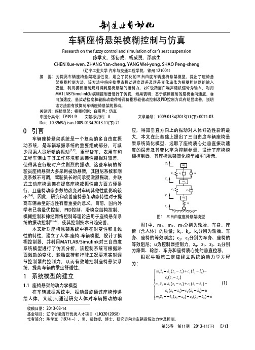
1 系统模型的建立
1.1 座椅悬架的动力学模型 在车辆减振系统中,振动最终通过座椅传递 给人体。文献[5]通过研究人体对车辆振动的响
(1)
收稿日期:2013-08-14 基金项目:辽宁省教育厅优秀人才项目(LJQ2012058) 作者简介:陈学文(1974 -),男,副教授,博士,研究方向为车辆系统动力学及控制。 第35卷 第11期 2013-11(下) 【71】
0.15 0.1 0.05 0 -0.05 -0.1 0 Passive PID Fuzzy
4 结论
本文对三自由度车辆座椅悬架进行了模糊控 制方法研究及其Simulink仿真,结果表明,本文 所建立的系统模型是有效的;采用主动控制技术 设计的模糊控制器是可行的,达到了预期的目的 和控制效果。该座椅悬架的模糊控制系统结构简 单,减振效果好,稳定性和鲁棒性高,可用于各 种车辆座椅减振系统,可为司乘人员提供安全舒 适的环境,具有广阔的应用前景。 参考文献:
= AX + Bu (t ) + Ezq X Y = CX + Du (t ) + Fzq
0.08 0.06 0.04
䏃䴶ᐙؐ
0.02
-0.02 -0.04 0 5 10 15 20
P
0
ᯊ䯈 W V
图2 C级路面
2 模糊控制器的设计
模糊控制器是模拟人类控制特征的一种语言 控制器,其设计主要包括控制器结构的选择、控 制器输入与输出变量的模糊化、模糊控制规则的 选取以及解模糊化等[7, 8]。 2.1 模糊控制器的结构 根据座椅悬架的性能要求和控制特性,采用 二维模糊控制器,结构如图3所示。
车辆座椅悬架模糊控制与仿真
Research on the fuzzy control and simulation of car’s seat suspension 陈学文,张衍成,杨威勇,邵鹏生 Chen Xue-wen, Zhang Yan-cheng, Yang Wei-yong, Shao Peng-sheng
探究史密斯模糊控制的汽车制动系统
探究史密斯模糊控制的汽车制动系统1. 引言1.1 史密斯模糊控制的定义史密斯模糊控制(Smith fuzzy control)是一种基于模糊逻辑的控制方法,旨在处理非线性、不确定性和复杂性系统的控制问题。
与传统控制方法相比,史密斯模糊控制能够更好地适应系统的动态变化,减少在系统参数未知或变化时的性能损失。
通过模糊推理和模糊推导等技术,史密斯模糊控制能够实现对系统的自适应调节,使得系统更加稳定和高效。
史密斯模糊控制的特点包括模糊化、规则库的建立、推理机制和解模糊化。
在模糊化阶段,输入和输出的模糊集合通过隶属函数进行描述,以便更好地反映出现实问题的不确定性和模糊性。
规则库的建立是史密斯模糊控制的核心,其中包含了专家经验和知识,通过规则的匹配和推理,确定系统的控制策略。
推理机制是基于模糊逻辑推导的方法,根据规则库中的规则进行推理,得出系统的控制动作。
解模糊化将模糊控制器输出的模糊结果转化为具体的控制信号,实现对系统的控制。
史密斯模糊控制是一种强大而灵活的控制方法,可以有效应对复杂系统的控制问题,具有很高的应用价值和推广前景。
在汽车制动系统等领域的应用将为系统性能提升和安全性提供重要支持。
1.2 汽车制动系统的重要性汽车制动系统是汽车安全性能的重要组成部分,它直接关系到车辆在紧急情况下的制动效果和驾驶员的操控感受。
一个可靠、高效的制动系统可以在紧急情况下帮助驾驶员快速减速或停车,从而减少交通事故的发生几率,保护车辆和乘客的安全。
制动系统的可靠性和性能直接关系到汽车的行驶安全和驾驶舒适性。
制动系统在汽车工程中的重要性不言而喻,它不仅直接影响车辆的安全性能,还与车辆的燃油经济性、驾驶舒适性等方面密切相关。
一个高效的制动系统不仅能够在紧急制动时快速响应,还能够有效减少制动能量的损失,提高整车的综合性能和燃油经济性。
探究史密斯模糊控制在汽车制动系统中的应用对于提高车辆的安全性能和驾驶舒适性具有重要意义。
通过引入史密斯模糊控制技术,可以进一步优化制动系统的性能,提高车辆的制动效果和驾驶品质,从而更好地满足现代社会对汽车安全性能的需求。
- 1、下载文档前请自行甄别文档内容的完整性,平台不提供额外的编辑、内容补充、找答案等附加服务。
- 2、"仅部分预览"的文档,不可在线预览部分如存在完整性等问题,可反馈申请退款(可完整预览的文档不适用该条件!)。
- 3、如文档侵犯您的权益,请联系客服反馈,我们会尽快为您处理(人工客服工作时间:9:00-18:30)。
CONTROL, PID CONTROL, ANDADVANCED FUZZY CONTROLFOR SIMULATING A NUCLEARREACTOR OPERATIONXIAOZHONG LI and DA RUAN*elgian Nuclear Research Centre (SCKoCENBoeretang 200, 8-2400 Mol, Belgium(Received 15 March 1999)Based on the background of fuzzy control applications to the first nuclear reactor in Belgium (BRI) at the Belgian Nuclear Research Centre (SCK.CEN), we have made a real fuzzy logic control demo model. The demo model is suitable for us to test and com- pare some new algorithms of fuzzy control and intelligent systems, which isadvantageous because it is always difficult and time-consuming, due to safety aspects, to do all experiments in a real nuclear environment. In this paper, we first report briefly on the construction of the demo model, and then introduce the results of a fuzzy control,a proportional-integral-derivative (PID) control and an advanced fuzzy control, in whichthe advanced fuzzy control is a fuzzy control with an adaptive function that canSelf-regulate the fuzzy control rules. Afterwards, we present a comparative study of thosethree methods. The results have shown that fuzzy control has more advantages in termsof flexibility, robustness, and easily updated facilities with respect to the PID control ofthe demo model, but that PID control has much higher regulation resolution due to its integration term. The adaptive fuzzy control can dynamically adjust the rule base,therefore it is more robust and suitable to those very uncertain occasions.Keywords: Fuzzy control; PID control; fuzzy adaptive control; nuclear reactorI INTRODUCTIONToday the techniques of fuzzy logic control are very mature in mostengineering areas, but not in nuclear engineering, though some research has been done (Bernard, 1988; Hah and Lee, 1994; Lin et al. 1997; Matsuoka, 1990). The main reason is that it is impossible to do experiments in nuclear engineering as easily as in other industrial areas. For example, a reactor is usually not available to any individual. Even for specialists in nuclear engineering, an official licence for doing any on-line test is necessary. That is why we are stillconducting projects such as "fuzzy logic control application" in BRl (the first nuclear reactor in Belgium) (Li and Ruan, 1997a; Ruan, 1995; Ruan and Li, 1997; 1998; Ruan and van der Wal, 1998). In the framework of this project, we find that although there are already many fuzzy logic control applications, it is difficult to select the most sui-table for testing and comparison of our algorithms. Moreover, due to the safety regulations of the nuclear reactor, it is not realistic to perform many experiments in BRl. In this situation, we have to conduct part of the pre-processing experiments outside the reactor, e.g., com-parisons of different methods and the preliminary choices of the parameters. One solution is to make a simulation programme in a computer, but this has the disadvantage that in which, however, the real time property cannot be well reflected. Therefore another solution has adopted, that is, we designed and made a water-levelcontrol system, referred to as the demo model, which is suitable for our testing and experiments. In particular, this demo model (Fig. 1) is designed to simulate the power control principle of BRl (Li et al., 1996a,b; Li and Ruan, 1997b).In this demo model, our goal was to control the water level in tower TI at a desired level by meansof tuning VL (the valve for large control tower T2) and VS (the valve for small control tower T3). The pump keeps on working to supply water to T2 and T3. All taps are for manual tuning at this time. VI and V2 valves are used to control the water levels in T2 and T3 respectively. For example, when the water level in T2 is lower than photoelectric switch sensor 1 then the on-off valve V, will be opened (on), and when the water level in T2 is higher than photoelectric switch sensor 2 then the on-off valve Vl will be closed (off). The same is true of V2. Only when both VI and V2 are closed V3 will be opened, because it can decrease the pressure of the pump and thereby prolong its working life. The pressure sensor is used to detect the height of water level in TI. So for TI, it is a dynamic system with two entrances and one exit for water flow.COMPARATIVE STUDY OF FUZZY CONTROLThe Demo Model StructureFIGURE 1 The working principle of the demo model.BRI is a 42-year old research reactor, in which the control method is the simple on-off method. Many methods called traditional meth- ods, when compared to fuzzy logic, are still very new to the BR1 reactor. One of these, proportional-integral-derivative (PID) control, has to be tested as well as fuzzy logic method. So far, we have tested the normal fuzzy control, traditional PID control, and an advanced fuzzy control on this demo model. To obtain a better demonstration, these three approaches have been programmed and integrated into one con- roller system based on the programmable logic controller (PLC) of the OMRON company. The purpose of tlus paper is to report comparative experimental results of these three methods from the demo model. Section 2 simply introduces a normal fuzzy control and its result.Section 3 introduces a PID control and its result.Section 4 introduces an advanced fuzzy control which is able to self-regulate the Fuzzy control rules. Section 5 compares the previous three methods and their results.2 FUZZY CONTROLThe fuzzy control algorithm in this demo model is a normal algorithm based on the Mamdani model. To simulate the BRl reactor, we use two fuzzy controllers (FLCl and FLC2) to control VL and VS separately (note: it is possible to use one fuzzy logic controller with two outputs to control VLand VS and the related result can be referred to (Li and Ruan, 1997b)). Let D be the difference between the actual value (P) of water level and the set value (S) and DD be the derivative of D, in other words, the speed and direction of the change of water level. VL and VS represent the control signal to VL (Iarge valve) and VS (small valve), respectively. When D is too big, we use FLC1 to control VL (main-tuning); When D is small, we use FLC2 to control VS(fine-tuning). We choose D and DD as inputs of the fuzzy logic con- troller, and VL or VS as the output of the fuzzy logic controller. D and DD must be fuzzified before fuzzy inference. Suppose the universes of discourse (or input variables' intervals) of D and DD are -d, dj and [-dd,dd], respectively. We use 7 fuzzy sets to partition hem, i.e., Negative Large (NL), Negative Middle (NM), Negative Small (NS), Zero (ZE), Positive Small (PS), Positive Middle (PM), and Positive Large (PL). As for VL and VS, because the result of fuzzy reasoning is also a fuzzy linguistic value, the universes of discourse of VL and VS also need to be fuzzified. We use those 7 fuzzy linguistic erms too. Symmetrical trianglar-shaped functions are used to define the membership functions for input variables (Li et al., 1995; 1996a,b), and singletons are for output variables (Ornron, 1992). Each fuzzy controller has one rule base which contains 49 fuzzy control rules. The its rule can be represented as the following form: if D is Ai and DD is Bi, then VL (or VS) is Ci where A, Bi, and Ci are fuzzy linguistical values, such as NL, PS, and so on. The above rule is sometimes abbreviated as (Ai, Bi : Ci). Figure 2 shows a control effect of a synthetic control process. It first goes up from 0 to 20cm then keeps on at 20 an, next drops down from 20 to 10 cm and finally keeps on at 10 cm.In view of this figure, we know that the fuzzy control has quick responses (quickly approaching the set value) and small overshoot (almost invisible), but with a small steady error (not so smooth in a steady state).COMPARATWE STUDY OF FUZZY CONTROLFIGURE 2 The control effect of fuzzy control to the demo model.3 PID CONTROLIn the PID control, it is difficult to control VL and VS separately like the previous fuzzy control with a good control result, because the integration term of the PID control needs some time, and this will result in an oscillation when switching control signal between VL and VS. From this point of view the PID control is worse than the fuzzy control. Therefore, in our tests, VL and VS have to be controlled by the same signal. We use the following formula:dtded i pe T dt T eK U(t)++=⎰By substitution,dt ded ie pe K dt K K U(t)++=⎰where U(I): control value to VL and VS at time r; e: the set value-the real value at time I; Kp: the proportional parameter and Kp = (1IPB) x loo%, where PB is the proportional band; Ki: the integrationFlGURE 3 The trajectory of the water level by the PID control.parameter and Ki = l/Ti where Ti is the integration time; Kd: the differential parameter and Kd = Td where Td is the differential time. In practice, a discrete form of the above formula is used)]1()([)](....)2()1([K e(t)K U(t)i P --++++=t e t e T K t e e e T sd s where T, is the sample period. Figure 3 shows a result of the PID control,where PB= l5%, Ti=30s, Td= 10s. In view of this figure, the PID control is very stable (very smooth in steady states), and has quick responses too, but with visible overshoots.4 ADVANCED FUZZY CONTROLThe kernel part of the fuzzy logic control is the fuzzy rule base with linguistic terms, though the membership functions and scale factors also have an important effect on the fuzzy logic controller. There are some papers which discuss how to adjust membership functions and/or scale factors (Batur and Kasparian, 1991; Chou and Lu, 1994; Tonshoff and Walter, 1994; Zheng, 1992). This section focuses on rules. Normally the methods of deriving rules can be broadly divided into two types, sourceable and non-sourceable. The sourceable method means the rules are obtained from some information source, such as human experience or historical input-output data. Experience has been widely used by the fuzzy engineers, especially by the early fuzzy engineers. The problem of using human experience is that it is time-consuming, and to some degree subjective. In order to overcome these problems, particularly avoiding the subjectivity, historical input -output data-if available can be used. To obtain rules from such data, many methods are used, one of the popular approaches is neural net- works (NN) (Berenji and Khedkar, 1992; Halgamuge and Glesner, 1994; Jang, 1992; Kosko, 1992; Li et al., 1995; Lin ez al., 1995; Takagiand Hayashi, 1991; Wang and Mendel, 1992). One problem of the sourceable method is that it depends strictly on the source which will be transformed into rules. In the case that the source is noisy, then the rules might be biased. Another problem of the sourceable method is that it is usually non-adaptive, i.e., all the rules are fixed, therefore it cannot perform well under a dynamic environment.The non-source- able methods are source-free and they produce and choose rules according to a performance measurement of the controller, such asgenetic algorithms (GA) (Karr, 1991; Lim et al., 1996; Qi and Chin, 1997) (mostly also generating membership functions and scale factors) and self-organizing controllers (SOC) (He er al., 1993; Li et al., 1996a,b; Lin et al., 1997, Procyk and Mamdani, 1979; Shao, 1988; Tanscheitand Scharf, 1988; Wu et al., 1992). With GA it is possible to find integratedly optimal parameters but GA is very computation rich, and furthermore, it is almost impossible to apply GA in a real complex system without a simulation model. Perhaps the SOC is the only method which has the following advantages: objective, adaptive, less computation required, more error-tolerant, and simple.FIGURE 4 An adaptive function is incorporated into a fuzzy control system.The general principle of the SOC is that the controller monitors its own performance and adjusts its control rules to improve performance for time-varying and unknown plants. The problem of the SOC show to perform the performance measurement. The basic way is to design a performance measurement table which looks like a fuzzy control rule table and to use it to assess the performance of the controller rules) (Procyk and Mamdani, 1979), but to design such a performance measurement table is also very difficult (Chung and Oh, 1993) and it is system-dependent. Based on the SOC, this section will introduce an adaptive method which uses a set of new norms to replace the ormer performance measurement. The new norms are very simpleand system-independent, therefore they can be easily applied to most fuzzy controllers. In this section, the advanced fuzzy control means the above SOC, in other words, a fuzzy control with an adaptive function, where the adaptive function contains two steps: performance judgement and changing fuzzy control rules. Figure 4 illustrates how an adaptive function is incorporated into the fuzzy control system. At the beginning of each cycle, the controller's last behaviour is judged and then the rule base is changed accordingly. In this cycle, the controller will use the new rule base and output the result to the controlled object. The behaviour of the new rule base will be judged and changed again in the next cycle.4.1 The Principle of the Adaptive FunctionLet D and DD represent error (the difference between the actual value and the desired value) and change in error, respectively. Let D(t) and DD(t) represent error and change in error at time t, respectively. They are two input variables. Let U be an output variable, and assume thetotal number of the rules is n, then every rule has the following form: if D is A, DD is Bi, then U is C;, i= 1,2 ,..., n, where A, Bi, and Ci are fuzzy linguistic values and i is an index pointing out each rule's position in the rule table (or the rule data file). User[i] to represent the fuzzy control magnitude (conclusion fuzzy set) of the ith rule, and let simply][i r7,6,5,4,3,2,1where 1=NL,2=NM,3=NS,4=ZE,5=PS,6=PMY7=PL.In general, a control locus may be expressed with Fig. 5, and it can be regarded as having up to four feature sections and four feature points. For each feature part, we offer a norm to guide the regulation of the fuzzy control rules. For example, the current water level P(t) is in the feature part (I), then after the fuzzy controlling using the current control rules, we measure the water level P(t + l) at the next time which has three possibilities:P(l) < P(t + 1) <S;P(t + 1) < S and P(t + 1) <P(t);P(t+l)>S.FIGURE 5 Any trajectory has up to four feature sections and four feature points.The related norm to guide how to change rules is the following:(i) if D(I + 1) 5 0 and DD(t + I) > 0, that is, P(t) < P(t + 1) 5 S, then r[i] = r[i](ii) if D(i f 1) < 0 and DD(t + 1) < 0, that is, P(t +1) < S and P(t + 1) < P(t), then r[i] = r[i] +a,(iii) if D(t + 1) > 0, that is, P(t + 1) > S, then r[i] = r[i] - a,where a is a step size and a = 1,2,3,4,5,6. In case (i), the fuzzy con-troller makes the water level P(t f 1) closer to the set value S, therefore the behaviour of the fuzzy controller is good, no rules should be changed; In case (ii), the fuzzy controller makes the water level P(t + 1) further from the set value S, therefore the behaviour of the fuzzy con- troller is not good,the strength is too weak and the action of the corresponding rules 'should be stronger; In case (iii), the fuzzy controller makes the water level P(t $1) overpass the set value S, therefore the behaviour of the fuzzy controller is not good, the strength is too strong and the action of the corresponding rules should be weakened. Not all rules but some of those that are activated in last cycle should be regulated. We use the following formula to describe which shouldbe adjusted:))()(A ()()(A j j i i DD B D DD B D ij C C ∧∨=∧= which means the ith rule is changed only if it is the largest activated among those activated rules which have the same conclusion part. For example, (NL, NM : PL) and (NM, NM : PL) are two activated rules and have the same conclusion part, i.e., PL. Comparing NL(D) A NM(DD) with NM(D) A NM(DD), the larger one corresponds to the rule which should be adjusted.4.2 An Experimental ResultTo guarantee no overshoot, the best way is to initialize all rules as the same conclusion part: NL, as shown in Table I. In this table, for example, NL at the row 2 and column 3 means: if D is NM and DD is NL then VL or VS is NL. All rules have the same conclusion part though condition parts are different. Figure 6 illustratesTABLE I The initial rule table for both FLCl and FLC2FIGURE 6 Comparison between adaptive fuzzy control and fuzzy control.the comparison result between fuzzy adaptive control and. fuzzy con-trol with the above rule base. In this example, the set value is 20cm.Both start from Ocm. During the first stage, i.e., increasing from zero,some analytic rules manipulate the valves and not fuzzy control. Onlyafter the water level reaches 18cm does the fuzzy controllers start tooperate VL and VS. Apparently, the adaptive fuzzy control has a muchbetter result by self-regulating gradually fuzzy control rules. The nor-mal fuzzy control without adaptive function cannot self-regulate rules,therefore it cannot draw up the water level.About 10 min later, we observe the rule tables on the screen and findboth rule tables have changed a lot. Table I1 gives the result of FLCl and Table 111 gives the resultof FLC2, where the regulated rules aremarked by bold fonts.4.3 Some Remarks for the Adaptive FunctionThe initial idea about the previously described norms of the adaptive function, which was published in (Li et al., 1996a,b), and where a simulated inverted pendulum system and a real industrial heating system were used to make testings, gave satisfactory results . a The parameter a is influential on the overshoot and response time (rise time). When cr is too big, there will be a large overshoot possibly; when a is too smaI1, possibly there will be a long response time (Li el al., 1996a,b). The adaptive function considers only the last value, that is, it uses P(r - 1) not P(t - T) (T is the delay) to decide P(t), but our experimental results show the effect is good, although the valves of the demo model have a maximum delay of 90 s. The adaptive function selects only some of the rules according to formula (1) for adjustment, not all activated rules like (Lin et al., 1997). This makes the transition of the rules more smooth, i.e., without or with less resonance. Selecting initial rules appropriately will benefit the control effect. For example, if the overshoot is strictly limited, we may initialize all rules with the conclusion part of NL, as was done in the previous experiment. Once some experience has been obtained, it can betransformed into the initial rules of the adaptive function, the advantage being that the rise time will be shorter (Li and Ruan, 1998). The rule, "if D is ZE and DD is ZE then U is ZE,"should be fixed, and this will help the system to become stable. The adaptive function is very helpful in keeping the system stable in a steady state. It cannot guarantee no overshoot if the initial rules are randomly selected. The adaptive function cannot adjust membership functions and scale factors.5 COMPARATIVE STUDYEach method has both advantages and disadvantages, the details of which are described in Table IV, where * is used to represent the degree of a property, and the more *, the higher the degree. For example, the realization of an adaptive fuzzy logic controller (FLC) is more difficult than a normal fuzzy controller, but a normal fuzzy controller is more difficult to realize than a PID controller. The PID control has the smallest static error and steady error. The dynamic regulation of TABLE IV Comparative study of FLC, PID and adaptive FLC the control rules in an adaptive controller can help in reducing the static error and steady error (Li et al., 1996a,b). As for robustness, it has been accepted that FLC is more robust than PID. Herein we also give one example, as shown as in Fig. 7. This experiment was carried out after tuning the Tap 1 (see Fig. 1) to make the outflow much smaller. We found that the reaction of FLC was better than that of PID, hough the FLC had a small static error. If we count the total number of * for each method, we will find that PID and FLC have the same score, 17. Adaptive FLC has a higher score of 20. This interesting result can be explained by the following facts. PID and FLC have their own strong points, and they compensate each other. Adaptive FLC adds an adaptive function to a normal FLC, therefore its score should be higher than that of FLC. A natural result is that combining FLC and PID should be better than each method alone. The comparative method above is perhaps a little subjective, but it does reflect some objective properties and relationships among those three methods. In the real world, one may use other ways to evaluate these methods. For example, if robustness is stressed, then it should be highly weighted when the total scores are calculated.For further descriptions of comparative studies between FLC and PID, readers may refer to Boverie et al. (1991), Chao and Teng (1997), Misir et al. (1996), Mizumoto (1995), Moon (1995), and Wu and Mizumoto (1996).FIGURE 7 FLC is more robust than PID.6 CONCLUSIONThis paper gives comparisons between fuzzy control, PID control, and advanced fuzzy control based on the experimental results of a demo model which simulates the control principle of the BR1 reactor. Fuzzy control is more robust than PID control, but with a well-characterized system, such as a reactor, it should be better to use a hybrid method which inherits the advantages of both methods. Furthermore, the adaptive fuzzy control is able to aid the designer in finding the fuzzy control rules, especially for systems possessing much of dynamical uncertainty. ReferencesBatur, C. and Kasparian, V. (1991), 'Adaptive expert control," International Journal ofControl, 54(4), 867-88 1.Berenji, H.R. and Khedkar, P. (1992). 'Learning and tuning firq logic controllersthrough reinforcements," IEEE Trans. Neural Networks, 3,724-740.Bernard, J.A. (1988). 'Use of a rule-based system for process control," IEEE ControlSystem Magazine, 8(5), 3- 13.Boverie, S., Demaya, B. and Titli, A. (1991). 'Fuzzy logic control compared with otherautomatic control approaches," Proceedings of the 30th IEEE-CDC Conjerence onDecision and Control, Brighton, UK, pp. 1212-1216.Chao, C.T. and Teng, C.C. (1997), 'A PD-like self-tuning fuzzy controller withoutsteady-state error," Fuzzy Sets and System, 87, 141 -154.Chou, C.H. and Lu, H.C. (1994), 'A heuristic self-tuning fuzzy controller," Fuzzy Setsand Systems, 61,249-264.Chung, B.M. and Oh. J.H. (1993). 'Control of dynamic systems using fuzzy learning algorithm," Fuzzy Sets and Systems, 59, 1 - 14.Hah, Y.J. and Lee, B.W. (1994), 'Fwy power control algorithm for a pressurized water reactor," Nuclear Technology, 106,242-252.Halgamuge, K. and Glesner, M. (1994), 'Neural networks in designing fuzzy systems for real world applications," Fuzzy Sets and Systems, 65, 1- 12.He, S.Z., Tan, S.H., Hang, C.C. and Wang, P.Z. (1993). 'Control of dynamical pro- cesses using an on-line rule-adaptive fuzzy control system," Fuzzy Sets und Systems, 54, 1 1-22.Jang, J.S.R. (1992), "Self-learning fuzzy controllers based on temporal back propaga- tion," IEEE Trans. Neural Networks, 3(S), 714-723.Karr, C.L. (1991). 'Design of an adaptive fuzzy logic controller using a genetic algo- rithm." Proc. 4th ICGA, pp. 450-457.Kosko, B. (1992), Fuzzy Systems and Neural Networks, Prentice-Hall, Englewood Cliffs, NJ.Li, X. and Ruan, D. (1997a), The Current Development of FLC Project at BRI and New Algorithms Design, Internal Report, SCKmCEN, Mol, Belgium.Li. X. and Ruan, D. (1997b). 'Constructing a fuzzy logic control demo model at SCKaCEN," Proceedings of the 5th European Congress on Intelligent Techniques and Sofr Computing (EUFIT '97). Aachen, Germany, pp. 1408-1412.Li, X. and Ruan, D. (1998), A Rule-Based Multi-Controller System Method with an Adaptive Function for the BRI Reactor, Internal Report, SCKmCEN, Mol, Belgium.Li, X., Shao, M. and Ruan, D. (1996a). Fuzzy Logic Control Demo Model, Internal Report. SCKoCEN, Mol, Belgium.Li, X., Bai. S. and Zhang, Z. (1996b), 'An introduction to a fuzzy adaptive control algo- rithm," Chinese Journal of Advanced Software Research, 3(1), 1 - 11.Li. X., Bai, S. and Liu, Z. (1995), 'An algorithm for self-learning and selfcompleting fuzzy control rules,' Informatica, 19, 301 -312.Lim, M.H., Rahardja, S. and Gwee, B.H. (1996), 'A GA paradigm for learning fuzzy rules," Fuzzy Sets and Systems. 82, 177- 186.Lin. C., Jeng, F. and Lee, C. (1997), "Hierarchical fuzzy logic water level control in advanced oiling water reactors," Nuclear Technology, 118(3), 254-263.Lin, C.T., Lin, C.J. and George Lee, C.S. (1995). 'Funy adaptive learning control net- work with on-line neural learning," Fuzzy Sets and Systems, 71.25-45.Matsuoka, H. (1990), 'A simple fuzzy simulation model for nuclear reactor system dynamics," Nuclear Technology, 94, 228-24 1.Misir, D., Malki, H.A. and ,Chen, G. (1996), "Design and analysis of a fuzzyproportional-integral-derivative controller," Fuzzy Sets andSysrems, 79,297-314. Mizurnoto, M. (1995). 'Realization of PID controls by fuzzy control method," Fuzzy Sers and Systems, 70, 171 - 182.Moon, B.S. (1995), 'Equivalence between fuzzy logic controllers and PI controllers for single input systems," Fuzzy Sets and Systems, 69, 105- 114.Omron (1992), C200H-FZ001 Fuzzy Logic Unit, Operation Manual, Ornron company. Procyk, T.J. and Mamdani, E.H. (1979), 'A linguistic self-organizing process con- troller,* Automat., 15(1), 15-30.Qi, X.M. and Chin, T.C. (1997). 'Genetic algorithms based fuzzy controller for high order svstems." Fuz:v Sets and Svstems. 91.279-284. . .Ruan. D. (i995). '~uzz;logic in the nuclear research world." Fuzzy Sets and System. 74(1), 5-13.Ruan, D. and Li, X. (1997). "The test of fuzzy logic control with a closed loop at BRI reactor," Proceedings of the 7th World Congress IFSA'97, Prague, Czech Republic, Vol. 3, pp. 126-131.Ruan, D. and Li. X. (1998). 'Fuzzy-logic control applications to the Belpan reactor I (BRI)," Computers and Artificial Intelligence. 17(2-3), 127-150.Ruan, D. and van der Wal, A.J. (1998). 'Controlling the power output of a nuclear reac- tor with fuzzy logic," Information Scienkes, 110. 151 - 177.。