Altium 中做自定义焊盘 2015-04-08
Altium Designer规则设计技巧过孔和焊盘

Altium Designer规则设计技巧过孔和焊盘一、过孔和焊盘的覆铜连接过孔和焊盘有三种连接状态:图一no connect(不连接);图二relief connect(十字形连接);图三direct connect(直接连接)覆铜时默认连接为十字形连接,如何改为直接连接呢?在PCB环境下,Design>Rules>Plane>Polygon Connect style,点中Polygon Connect style,右键点击new rule新建一个规则点击新建的规则既选中该规则,在name框中改变里面的内容即可修改该规则的名称,默认是PolygonConnect_1,现我们修改为Via(改为任何名字都可以),选项Where The Frist Object Matches选Advanced(Query),Full Query输入IsVia(大小写随意),Connect Style选Direct Connect,其他默认设置,点击下边的priorities把Via规则优先级置最高,前面的优先级高于后面的(1高于2)如下图这样过孔和覆铜(过孔为GND,覆铜为GND)的连接就会变为直连了,而不是默认的十字形连接。
如下图左为十字形连接,右为直连。
从上面可以看出过孔VIA的连接已经改变,可是焊盘确没有变化。
如果想过孔和焊盘都用直连方式,那在Full Query修改为IsVia or Ispad,更新下刚才的覆铜,地焊盘也全连接了如下图这样虽然焊盘和覆铜全连接上了,可是所有表面贴元件的地也跟覆铜全连接上,而我们要的只是某个直插元件焊盘的地和覆铜直连。
方法是,假如只要让JP3元件焊盘和地直连,其他贴片元件为十字形连接。
则修改Full Query 为IsVia or InComponent('JP3')(可以是多个元件Isvia or InComponent('U1') OR InComponent('U2') OR InComponent('U3'))重新覆铜则效果如下二、过孔和焊盘间隔的设置。
Altium Designer中绘制多边形焊盘

Altium Designer中绘制多边形焊盘Author:JackmonData: 2014/5/28Mail: jackmon@简介:This document briefly illustrates how to build a footprint with pads in irregular shape.下面已FPC中一个不规则的焊盘为例,完成排线制作:1.新建一个PCB文件(请注意,是PCB文件,而不是Library文件),然后根据数据手册,在TOPOverly层绘制出焊盘的形状。
2.切换到布线层(TOP或者BOTTOM)选中整个TOPOverly的外形,执行Tools->Convert->Create RegionFrom Selected Primitives,如此就得到了数据手册中的不规则形状。
3.按照同样的方法绘制其他几种形状的焊盘。
4.创建一个PCB的Library,讲上面的绘制的不规则铜片复制到PCB Library里面的TopLayer层。
同时复制各个形状,组成FPC的引脚数量。
(Tips:复制的时候请注意参考点的选择。
)5.选中全部的不规则焊盘,分别对齐复制到Top paster和Top Solder。
6.添加焊盘到每个不规则焊盘上7.至此,封装所有需要的元素准备完毕,完成绘制。
8.把封装库添加到项目中,完成原理图设计后,导入PCB中,会出现绿色的报警信息。
9.在PCB界面中,使用design->netlist->configure physical nets来对这些无网络的元素进行处理,TIPS: 对于有重复命名的引脚,需要手动的去调整,系统默认每个引脚的命名是不同的。
Altium Designer中绘制多边形焊盘

Altium Designer中绘制多边形焊盘Author:JackmonData: 2014/5/28Mail: jackmon@简介:This document briefly illustrates how to build a footprint with pads in irregular shape.下面已FPC中一个不规则的焊盘为例,完成排线制作:1.新建一个PCB文件(请注意,是PCB文件,而不是Library文件),然后根据数据手册,在TOPOverly层绘制出焊盘的形状。
2.切换到布线层(TOP或者BOTTOM)选中整个TOPOverly的外形,执行Tools->Convert->Create RegionFrom Selected Primitives,如此就得到了数据手册中的不规则形状。
3.按照同样的方法绘制其他几种形状的焊盘。
4.创建一个PCB的Library,讲上面的绘制的不规则铜片复制到PCB Library里面的TopLayer层。
同时复制各个形状,组成FPC的引脚数量。
(Tips:复制的时候请注意参考点的选择。
)5.选中全部的不规则焊盘,分别对齐复制到Top paster和Top Solder。
6.添加焊盘到每个不规则焊盘上7.至此,封装所有需要的元素准备完毕,完成绘制。
8.把封装库添加到项目中,完成原理图设计后,导入PCB中,会出现绿色的报警信息。
9.在PCB界面中,使用design->netlist->configure physical nets来对这些无网络的元素进行处理,TIPS: 对于有重复命名的引脚,需要手动的去调整,系统默认每个引脚的命名是不同的。
cadence学习(二) 特殊自定义焊盘建立
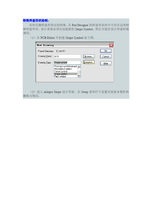
特殊焊盘形状绘制:有些引脚焊盘形状比较特殊,在Pad Designer的焊盘形状库中不存在这类特殊焊盘外形,设计者就必须先创建新的Shape Symbol,然后才能在设计焊盘时被调用。
(1)在PCB Editor中创建Shape Symbol如下图。
(2)进入Allegro Shape设计界面,在Setup菜单栏下设置页面基本属性和栅格点情况。
(3)添加各类图形:执行Shape菜单栏下的相关命令,用以添加不同的形状。
在金手指图形设计中,先执行Shape/Rectangular,Options窗口就选择默认设置,即Etch、Top和形状填充Static solid,在命令栏中输入起始点坐标按回车键、终点坐标按回车键,就可以从始终点直接画出该矩形。
此后再根据这种方法,执行Shape/Circular命令添加两端圆形。
(4)合并各类图形:执行Shape/Merge Shapes命令,对分散的图形进行适当的整合,将不同图形合并成一个Shape Symbol。
(5)保存该图形:执行Create Symbol命令创建图形符号,选择创建路径,则在相应的路径下得到*.ssm文件即为图形符号,并将该图形符号保存到设计者自己的图形符号文件夹中。
(6)设定图形库:在PCB Editor中,执行Setup/User Preferences,弹出User Preferences Editor对话框,点击Paths/Library,在右边编辑psmpath库调用的路径,添加设计者图形库路径。
(7)调用图形符号:完成Shape Symbol的建立和库路径设置后,启动Pad Designer焊盘编辑工具,在Layers选项卡下,点击Shape后面的浏览按钮,在弹出的Select shape symbols对话框中就可以调用新建的图形符号了。
这样就可以完成创建特殊图形符号的焊盘,然后在Package Symbol中就可以调用这些特殊焊盘来添加引脚了。
Cadence焊盘制作指南

Cadence焊盘制作指南焊盘制作指南Cadence 16.2有专用的焊盘设计工具Pad Designer,简单易用,非常便于制作孔式焊盘和贴片焊盘。
1. Flash焊盘制作在插装型焊盘中Thermal Relief经常使用,一般最好采用Flash 型,这样在正负片模式中通用。
1.1 建立Flash焊盘File→new→Flash symbol● Drawing Name中输入名字TR OD_ID_W-45(见FLASH焊盘命名规范)。
● 点Browse,定位Flash存放位置,点OK确定。
1.2 绘制Flash焊盘Add→Flash● Inner diameter中输入内径● Outer diameter中输入外径● Spoke width中输入宽度● Number of spokes中选择数目● Spoke angle中选择角度1.3保存Flash焊盘● File→Creat Symbol保存为不可放在PCB上的.PSM档。
● File→Save保存为供以后修改的图形.DRA档。
其实点Save后会自动保存两者。
2. Padstack的剖面插件焊盘从上到下依次是SolderMask_T op,PIN的Top,Thermal relief,Anti Pad,PIN的Bottom和SolderMask_Bottom。
3. 打开焊盘设计软件开始→所有程序→Cadence 16.2→PCB Editor→Utilities→Pad Designer4. 参数设置4.1 设置单位和精度Pad Designer→Pa rameters● Units中选择单位Mils/Inch/Millimeter等,● Decimal places选择精度1,4.2 设置定位孔如果焊点为Through-Hole型,须定义孔径和钻孔符号。
如果为SMD形,不需要设置孔径和钻孔符号。
4.2.1 设置钻孔类型和尺寸● Hole type选择Circle Drill(圆孔)/Oval Slot(椭圆槽)/Rectangle Slot(矩形槽)● Plating中选择Plated(金属化)/Non Plated(非金属化)● Dr ill diameter中填入孔径大小4.2.2 设置钻孔图例● Figure为钻孔符号效果● Characters为标示字符串● Width为符号宽度● Height为符号高度5. 层设置5.1 设置Bgn LayerL ayers→BEGIN LAYER5.1.1 Regular Pad● Geometry中选择Circle(圆)/Square(方型)/Oblong(椭圆形)/Retangle(矩形)/Octagon (八边形)/Shape(任意形状)● Width中输入宽度● Heigth中输入高度如果是不规则形状,需要导入shape。
制作焊盘(元件封装)步骤
制作焊盘(元件封装)步骤制作焊盘(元件封装)步骤先制作引脚焊盘,再制作元件封装。
焊接通孔-焊盘制作1.查元件/接插件数据⼿册(Datasheet),找到“Layout Recommendation”或“MountingPattern”页。
2.找到通孔推荐钻孔尺⼨,⽐如:如图Ф0.89x10其中0.89即为推荐钻孔直径,x10 表⽰同样的孔有10个。
3.(⼀般取0.3mm⾜够焊接操作)⽐如:钻孔直径为Ф0.89,则焊盘外径可取Ф1.19mm或Ф1.2mm。
4.⾜够。
⽐如:钻孔直径为Ф0.89,焊盘外径取Ф1.2mm,则Soldermask直径可取Ф1.3mm。
5.确定热风焊盘(Flash Symbol)(两种):⽅热风焊盘(PIN1)命名:str A x A o B x B (命名规则)解释:str: Square Thermal Relief;⽅形散热槽A x A:确定阻焊盘Anti pad 边长= A;B x B: 内边长;圆热风焊盘命名:tr ID x OD x SW – SA (命名规则)解释:tr: Thermal Relief;散热槽内径;⼀般取焊盘外径即可。
OD: Out Diameter 外径;)⼀般加0.1mm⾜够。
保留整数位,⼀般取0.5mm。
SA:Spoke Angle 开⼝⾓度。
SA = 45度。
6.给通过孔焊盘命名(两种):⽅焊盘(PIN1)命名: A Sq B dA: 正⽅形焊盘边长;B:钻孔直径;Sq: Square; d: 钻孔的孔壁必须上锡⽐如:2Sq1p7d ⽅焊盘,正⽅形焊盘边长2mm,钻孔直径1.7mm。
圆焊盘命名: A Cir B dA: 焊盘外径B:钻孔直径;Cir:Circle;d: 钻孔的孔壁必须上锡⽐如:2Sq1p7d 圆焊盘,焊盘外径2mm,钻孔直径1.7mm。
7.启动软件“Allegro PCB Design GXL”制作热风焊盘。
File→New,Drawing Type选择:Flash Symbol。
AltiumDesigner敷铜与过孔或焊盘连接方式设置技巧

A l t i u m D e s i g n e r敷铜与过孔或焊盘连接方式设
置技巧
集团标准化办公室:[VV986T-J682P28-JP266L8-68PNN]
Altium Designer敷铜与过孔或焊盘连接方式设置技巧
1.在PCB工程界面:执行D——R,在Designer Rules-Electrical里
添加新规则
2.“name”栏名称可改可不改,在“where the first object matche s”栏选中“高级的询问”,再在右边“全部询问”输入“IsVia”,(键入该信息的语法可以借助“询问助手”来完成)。
这样设置的意思是设置过孔的连接方式。
用“询问助手”如下图
3.在“关联类型”栏按前头下拉选中“direct connect”。
这样敷铜与过孔的连接方式就是实心连接了。
4.用同样的方法设置敷铜与焊盘的连接,也一样得到这样敷铜与焊盘的连接方式就是实心连接。
使用altiumdesigner21极坐标绘制异形焊盘比如焊接螺母的环绕焊盘

使⽤altiumdesigner21极坐标绘制异形焊盘⽐如焊接螺母的环绕
焊盘
先看⼀张图
在回流焊时,不能直接做⼀个⼤圆圈焊盘来焊接螺母,这样焊锡膏因为流动问题,可能会导致螺母歪斜
⼚家推荐的焊盘形状右上⾓
所以需要绘制异形焊盘
⾸先进⼊ad的封装库⼯作界⾯
在库中点右下⾓PCB编辑界⾯–>右下⾓Panels–>Properties–>Grid Manager–>Add–>Add Polar Grid
会变成这样⼦
然后Properties中找到新建的极坐标,双击
配置⼀下起始⾓度,再根据数据⼿册配置⼀下半径
然后再把颜⾊搞⼀下,⽅便观看
然后画好内外径的线,这个线宽度最好不要搞那么⼤,因为这个线后续会作为焊盘的⼀部分
我这⾥为了截图明显,加粗了很多
再⽤导线把内外环封闭起来
转换⼀下,快捷键TVE(从选择的元素创建区域)
然后再双击转换后的区域设置⼀下paste mask和solder mask为rule
这个很重要
不然这些部分就会被阻焊油堵盖
完成后,使⽤三弟(3D)预览⼀下,确定铜⽪是露出的
再加上三维模型
效果棒棒的哈
参考altium官⽅教程。
Cadence焊盘制作指南

焊盘制作指南Cadence 16.2有专用的焊盘设计工具Pad Designer,简单易用,非常便于制作孔式焊盘和贴片焊盘。
1. Flash焊盘制作在插装型焊盘中Thermal Relief经常使用,一般最好采用Flash型,这样在正负片模式中通用。
1.1 建立Flash焊盘File→new→Flash symbol● Drawing Name中输入名字TR OD_ID_W-45(见FLASH焊盘命名规范)。
● 点Browse,定位Flash存放位置,点OK确定。
1.2 绘制Flash焊盘Add→Flash● Inner diameter中输入内径● Outer diameter中输入外径● Spoke width中输入宽度● Number of spokes中选择数目● Spoke angle中选择角度1.3保存Flash焊盘● File→Creat Symbol保存为不可放在PCB上的.PSM档。
● File→Save保存为供以后修改的图形.DRA档。
其实点Save后会自动保存两者。
2. Padstack的剖面插件焊盘从上到下依次是SolderMask_Top,PIN的Top,Thermal relief,Anti Pad,PIN的Bottom和SolderMask_Bottom。
3. 打开焊盘设计软件开始→所有程序→Cadence 16.2→PCB Editor→Utilities→Pad Designer4. 参数设置4.1 设置单位和精度Pad Designer→Parameters● Units中选择单位Mils/Inch/Millimeter等,● Decimal places选择精度1,4.2 设置定位孔如果焊点为Through-Hole型,须定义孔径和钻孔符号。
如果为SMD形,不需要设置孔径和钻孔符号。
4.2.1 设置钻孔类型和尺寸● Hole type选择Circle Drill(圆孔)/Oval Slot(椭圆槽)/Rectangle Slot(矩形槽)● Plating中选择Plated(金属化)/Non Plated(非金属化)● Drill diameter中填入孔径大小4.2.2 设置钻孔图例● Figure为钻孔符号效果● Characters为标示字符串● Width为符号宽度● Height为符号高度5. 层设置5.1 设置Bgn LayerL ayers→BEGIN LAYER5.1.1 Regular Pad● Geometry中选择Circle(圆)/Square(方型)/Oblong(椭圆形)/Retangle(矩形)/Octagon (八边形)/Shape(任意形状)● Width中输入宽度● Heigth中输入高度如果是不规则形状,需要导入shape。
AltiumDesigner异型焊盘封装的创建

AltiumDesigner异型焊盘封装的创建
用Altium Designer创建下图所示的插件异型焊盘封装。
步骤一:首先,添加带通孔的焊盘
步骤二:在Buttom层place Circle和line,构成如下形状的封闭区间
注意,圆弧的半径和焊盘的半径相等,长度根据需要自定义。
步骤三:选中上面的封闭区间,进行Tools-Convert-Create region from selected primitives。
得到如下的区域
步骤四:双击该区域,进行如下操作,单击Ok
切换到bottom paste层和bottom solder层,可以看到发生了如下变化
此时可以把刚才在bottom层画的边框线删除。
步骤五:切换到bottom层,把上面创建的区域复制到与焊盘重合,如图
然后再将该区域复制并翻转过后与焊盘上半部分重合,如图
这样创建的焊盘就是top层为圆形焊盘,bottom层为这种长条形的焊盘。
其它的异型焊盘可以采用类似的方式去创建。
这里需要理解paste层和solder层的作用,paste层为助焊层,在该层凡是有画的区域或者线,就意味着该区域或线在制版的时候会加上助焊材料(锡膏),solder层为阻焊层,在该层有画的区域或者线,意味着在该区域会防止绿油覆盖,也就是所谓的开窗。
步骤六:接下来只需要复制粘贴,再在top overlay层画一个圆就完成了这样一个封装的创建。
altium designer铺铜时过孔和焊盘的连接形式的设置
altium designer铺铜时过孔和焊盘的连接形式的设置Altium Designer是一款专业的电子设计自动化(EDA)软件,广泛应用于电子工程师和电路设计师的工作中。
在电路板设计过程中,铺铜是一项至关重要的工作,它可以直接影响到电路板的性能和可靠性。
本文将详细介绍如何在Altium Designer中进行铺铜操作,以及如何设置过孔和焊盘的连接形式。
在Altium Designer中进行铺铜操作,首先需要在设计区域选择铺铜区域,然后设置铺铜参数,如铺铜厚度、间距等。
接下来,将过孔和焊盘添加到铺铜区域,以便实现电路板上的连接。
在这个过程中,过孔和焊盘的连接形式设置尤为重要,它将直接影响到电路板的性能。
在Altium Designer中,过孔和焊盘的连接形式主要有以下几种:1.焊盘连接:焊盘连接是指焊盘与过孔之间直接连接,这种连接形式适用于高速信号传输和低速信号传输。
焊盘连接可以有效减小信号反射,提高信号传输质量。
2.孔连接:孔连接是指过孔与焊盘之间通过一个孔进行连接。
这种连接形式适用于多层电路板设计,可以降低信号干扰,提高电路板性能。
3.桥接连接:桥接连接是指过孔与焊盘之间通过一个桥接结构进行连接。
这种连接形式适用于大电流、高电压电路设计,可以提高电路板的散热性能和抗干扰能力。
4.空连接:空连接是指过孔与焊盘之间不直接连接,而是通过空气间隙进行连接。
这种连接形式适用于射频电路设计和微波电路设计,可以有效减小电磁干扰,提高电路性能。
在实际电路板设计中,根据电路需求和性能要求,合理选择过孔和焊盘的连接形式至关重要。
以下几点建议供大家参考:1.针对高速信号传输,建议采用焊盘连接或孔连接;2.针对大电流、高电压电路,建议采用桥接连接;3.针对射频电路和微波电路,建议采用空连接;4.针对多层电路板设计,注意合理设置层间连接形式,降低信号干扰。
总之,在Altium Designer中进行铺铜操作时,掌握过孔和焊盘的连接形式设置技巧,将有助于提高电路板的性能和可靠性。
[整理]allegro焊盘制作
![[整理]allegro焊盘制作](https://img.taocdn.com/s3/m/7e9b1deb5022aaea998f0f67.png)
Cadence_SPB16.2入门教程——焊盘制作焊盘制作1.1 用Pad Designer制作焊盘Allegro中制作焊盘的工作叫Pad Designer,所有SMD焊盘、通孔焊盘以及过孔都用该工具来制作。
打开程序->Cadence SPB 16.2->PCB Editer utilities->Pad Designer,弹出焊盘制作的界面,如图1.1所示。
图1.1 Pad Designer工具界面在Units下拉框中选择单位,常用的有Mils(毫英寸),Millimeter(毫米)。
根据实际情况选择。
在Hole type下拉框中选择钻孔的类型。
有如下三种选择:Circle Drill:圆形钻孔;Oval Slot:椭圆形孔;Rectangle Slot:矩形孔。
在Plating下拉框中选择孔的金属化类型,常用的有如下两种:Plated:金属化的;Non-Plated:非金属化的。
一般的通孔元件的管脚焊盘要选择金属化的,而元件安装孔或者定位孔则选择非金属化的。
在Drill diameter编辑框中输入钻孔的直径。
如果选择的是椭圆或者矩形孔则是Slot size X,Slot size Y两个参数,分别对应椭圆的X,Y轴半径和矩形的长宽。
一般情况下只要设置上述几个参数就行了,其它参数默认就可以。
设置好以后单击Layers标签,进入如图1.2所示界面。
图1.2 Pad Designer Layers界面如果制作的是表贴元件的焊盘将 Singel layer mode 复选框勾上。
需要填写的参数有:BEGINLAYER层的Regular Pad;SOLDEMASK_TOP层的Regular Pad;PASTEMASK_TOP层的Regular Pad。
如图1.3所示。
图1.3 表贴元件焊盘设置如果是通孔焊盘,需要填写的参数有:BEGINLAYER层的Regular Pad,Thermal Relief,Anti Pad;DEFAULTINTERNAL层的Regular Pad,Thermal Relief,Anti Pad;ENDLAYER层的Regular Pad,Thermal Relief,Anti Pad;SOLDEMASK_TOP层的Regular Pad;PASTEMASK_TOP层的Regular Pad。
Protel DXP技巧统一修改焊盘
Protel DXP技巧统一修改焊盘
整板焊盘统一修改内外直径。
1)在布线之前右键单击任何一个焊盘,在弹出的对话框中选择第一个菜单,如下图:
2)在如下图的对话框中点击在any右方的下拉小箭头,从中选择same。
3)此时,符合条件的焊盘会高亮显示,其他部分被屏蔽。
在弹出的inspector对话框中红色部分输入统一的焊盘内直径,在蓝色区域输入焊盘外直径,注意x size和y size要一致。
修改后关闭inspector对话框。
4)关闭后所有焊盘已经统一修改好,但是除了焊盘其他部分依然屏蔽,只要单击右下方的clear键即可。
如果要求是改为公制的尺寸,则第一步要用View下拉菜单的最后一个菜单。
如下图:。
Aultium Designer AD 铺铜增加热焊盘方法
Aultium Designer(AD)
铺铜中设置个别元件为热焊盘连接方法
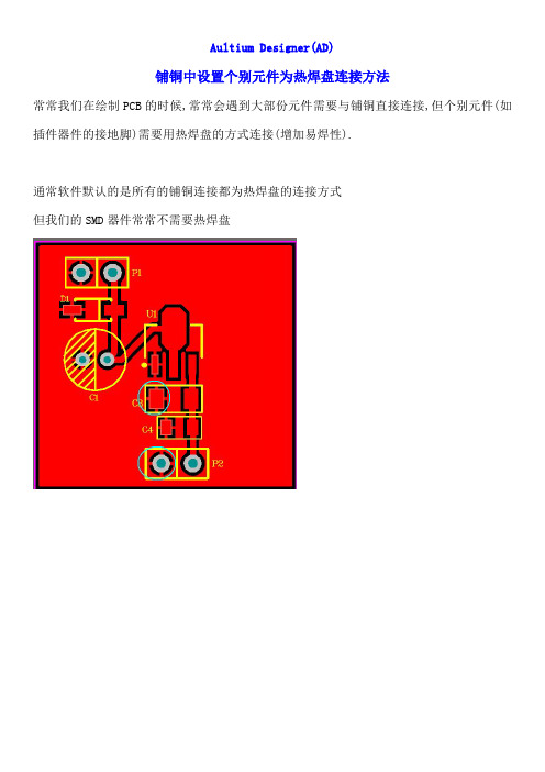
常常我们在绘制PCB的时候,常常会遇到大部份元件需要与铺铜直接连接,但个别元件(如插件器件的接地脚)需要用热焊盘的方式连接(增加易焊性).
通常软件默认的是所有的铺铜连接都为热焊盘的连接方式
但我们的SMD器件常常不需要热焊盘
第一步,按快捷键DR进入规则设置对话框
在这里选择PolygonConnect规则点开后,可以在这里设置铺铜的连接方式,这里更改的是全局的,即所有的连接都会按照这个规格连接
第二步,新建一个规则,
对应设置所需要的参数如下图
设置完成后确认,回到PCB重新铺铜即可
马文。
Cadence不规则焊盘制作资料
Cadence Allegro不规则焊盘的制作当我们使用EDA工具进行PCB设计时,由于设计的多样性、器件的多样性,经常会遇到一些比较复杂、奇怪的器件焊盘,因此,如何准确、快速的创建和编辑这些复杂的异形焊盘往往会成为我们不得不面对的问题。
创建这些异形焊盘,我们大体可以分为三大步骤:1、创建不规则焊盘Regular焊盘对应的Shape;2、Z-Copy方式创建不规则焊盘Soldermask层对应Shape;3、在Pad Designer中创建不规则焊盘这样完成了不规则异形焊盘后,我们就可以在此基础之上进行器件封装库的创建与编辑。
在所有的复杂异形焊盘中,我们基本上可以分为两类:一类可以由实心Shape构成的异形焊盘,一类是由镂空Shape构成的异形焊盘。
针对这两种异形焊盘,我们可以用以下几种方式进行快速、准确的创建与编辑。
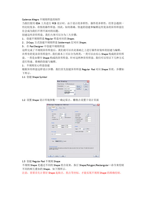
1、不规则实心焊盘创建根据异形焊盘这样设计步骤,我们首先创建异形焊盘Regular Pad对应Shape形状,步骤如下所示。
1.1 创建Shape Symbol1.2 设置Shape设计环境参数——确定原点、栅格点设置于设计页面1.3 创建Regular Pad不规则Shape不规则Shape是通过不同的Shape组合而来,执行Shape/Polygon/Rectangular…命令来绘制不同的相互叠加的Shape,如下图所示。
注意:需要首先计算好Shape起始点,拐点等坐标,才能实现不规则Shape的准确绘制。
准确完成不同Shape的叠加,使得Shape外形符合异形焊盘外形要求后,执行Shape/Merge Shape命令即可将叠加的Shape实现合成,则异形焊盘的外形成功完成。
保存该Shape,以便Pad Designer调用进行焊盘设计。
1.4 创建Soldermask Pad不规则Shape由于焊盘Soldermask层比之Regular Pad大出0.1mm左右,使我们需要在上图所示的Regular Shape上外扩0.1mm左右,成为新的不规则Shape,以便可以在Pad Designer中被调用至焊盘阻焊层。
在ADS的layout上绘制焊盘注意事项
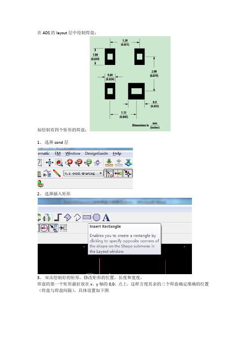
在ADS的layout层中绘制焊盘:
如绘制有四个矩形的焊盘:
1、选择cond层
2、选择插入矩形
3、双击绘制好的矩形,修改矩形的位置,长度和宽度,
焊盘的第一个矩形最好放在x、y轴的0,0,点上,这样方便其余的三个焊盘确定准确的位置(焊盘与焊盘间隔),具体设置如下图
4、绘制第一个矩形的右边矩形,主要计算好第二个矩形起始点坐标即可确定两个矩形间隔X坐标计算0.6/2+1.15-0.9/2=1,y坐标仍为0;
5、第三个类似,x坐标为0,y坐标为0.6/2+2-1/2=0.8
6、一次类推,绘制其它形状也是这样的方法,只要确定好一个坐标点(0,0)其余的都可计
算出准确的坐标点。
AltiumDesigner中创建异形焊盘方法
中创建异形焊盘方法 AltiumDesigner中创建异形焊盘方法
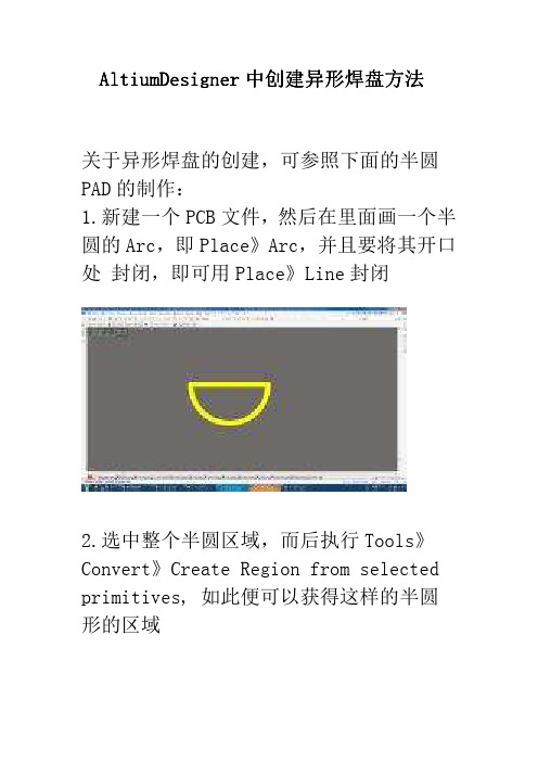
关于异形焊盘的创建,可参照下面的半圆PAD的制作:
1.新建一个PCB文件,然后在里面画一个半圆的Arc,即Place》Arc,并且要将其开口处 封闭,即可用Place》Line封闭
2.选中整个半圆区域,而后执行Tools》Convert》Create Region from selected primitives, 如此便可以获得这样的半圆形的区域
3.创建一个PCB的库,将刚刚的半圆区域复制到Pcb库里面的Top Layer层。
然后放贴片 Pad,将pad放在半圆的区域,同时在Top paster 和Top Solder 里面画同样形状的半圆, 此时只要复制,粘贴即可实现。
保存PCB的库文件。
将各元素准备好后重叠
4.将自建的这个库添加到Libraries里面,以便将其放到PCB文件里面。
5.当将半圆的Pad放到PCB之后,即会发现出现绿色的报警信息。
6.单击Design》NetList》Configure Physical Nets。
由此,半圆Pad创建完毕。
最后效果图
以此类推,其他形状的焊盘也可以通过这样的方式进行创建。
- 1、下载文档前请自行甄别文档内容的完整性,平台不提供额外的编辑、内容补充、找答案等附加服务。
- 2、"仅部分预览"的文档,不可在线预览部分如存在完整性等问题,可反馈申请退款(可完整预览的文档不适用该条件!)。
- 3、如文档侵犯您的权益,请联系客服反馈,我们会尽快为您处理(人工客服工作时间:9:00-18:30)。
Creating a Custom Pad ShapeModified by on 8-Apr-2015LanguageTworzenie padów o niestandardowych kształtachJapaneseStandard Pad AttributesAltium Designer's standard pad object can:Be set to a number of different shapes, including round, rectangular, rounded rectangular andqoctagonal.Be sized differently in the X and Y directions, extending the range of shapes that can be created.qBe customized to change the shape for each layer of the board.qHave a round or slotted hole, which can be offset from the pad center.qCreating a Custom Pad ShapeTo creates a different shape from those listed above, you create a custom pad shape. Custom pad shapes are created by placing other design objects, such as arcs, fills, lines or regions, to build up the copper shape required for the pad. A small pad is included within the shape to define the connection point in the pad, and if required, the drill hole location and size.There is a huge variety of pad shapes needed for component footprints.*Any Altium Designer design object can be used to build up the required copper shapes needed for the pads. Choose the object to suit the shape required, for example the copper contact area for theswitch shown below has been created from a series of track objects, surrounded by 2 arc objects.The printed contact for a membrane switch.Strategies for Creating Custom ShapesFor complex shapes the Solid Region object is ideal, as a polygonal object it can be used to create virtually any shape. The following footprint was created by first setting the grid to suit the zig-zag requirements of the copper, and then placing one region object to give a single zig-zag shape. This was then copied the required number of times to define the copper area of the capacitive slider footprint. Alternating surface mount and through-hole pads were added on alternating ends of each zig-zag to define the connection points.Use the Solid Region object to create unusual shapes needed in a pad.Using Guides to Place a RegionIf the pad shape requires a shape defined at specific locations that do not fall onto a grid, it can be more efficient to define linear or point guides, and then place on these guides. The animation below shows an wedge-shaped pad being created by:1.Defining 4 Point Guides at the required locations in the Guide Manager dialog,2.Disabling the Snap to Grid option and enabling the Snap to Guides options,3.Placing a Solid Region with corners on these Point Guides,Copying and pasting the Solid Region the required number of times, at the required angular4.intervals. The animation does not show placement of the pads, or the Solder Mask definition, which was done by placing a circle on the Solder Mask layer.Brief animation showing the creation of a radial style set of custom pads, using Point Guides.Converting an Outline to a RegionAnother approach to defining an unusual pad shape is to first define a closed outline of the shape using lines and arcs, and then convert this outline to a Solid Region. The pads in the surface mount inductor footprint shown below were created using this approach.The following steps were taken:Set the grid to suit the outer dimensions of the pad.1.2.Added 2 vertical and 2 horizontal guides to simplify the line/arc placement process,3.Defined a polar grid with the radial step set to suit the radius of the inner curve on the pad,4.Placed Line/Arc objects, as shown in the animation below,5.Placed an Arc, using the Heads-up display to set the radius and the horizontal Lines to snap the start and end points,6.Resized the horizontal Lines down to meet the ends of the Arc,7.Selected the Lines and Arcs, then ran the Tools » Convert » Create Region from Selected Primitives command,8.Edited the Region to set it to the Top Layer, and enable the Mask Expansion option,9.To finish the component, you would then copy and paste the Region to define the second pad shape, place a small pad in each Region to define a connection point in each pad, then add the Component Overlay.Brief animation showning a custom pad being created by defining an outline, then converting that to a Solid Region. Defining the Solder and Paste MaskThere are essentially 2 approaches for defining the solder and paste mask requirements for a custom pad.Use Altium Designer's calculated mask capability.1.Define the mask requirements manually by placing objects on the mask layer(s).2.Calculated MasksAny Altium Designer primitive object can have a calculated Solder and/or Paste Mask, which can either be a user-specified amount, or controlled by Altium Designer's rule system. This is achievedenabling the appropriate Mask Expansion setting in the object's dialog, as shown in the image below.Enable the required Mask Expansion, selecting between from Rule or user-specified value.Manually Defined MasksWhen the mask opening requirements are not simply an expansion or contraction of the copper shape, it will not be possible to use a calculated mask. In this case you place suitable design objects on the required Mask layer. Keep in mind that the Solder Mask is defined in the negative, that is, the placed objects define openings in the Solder Mask layer. The following image shows a printed button that has the solder mask opening defined by a manually placed full circle arc, placed on the Top Solder Mask layer.If the mask shape is more than an expansion/contraction of the pad shape, define the mask by placing objects to create the required shape.Routing Connections for Custom PadsSince Altium Designer is able to detect and resolve routing connections to any copper object, there are no specific limitations on how you route to a custom pad.Thermal Connections for Custom PadsCustom pads are often created for components that have larger, unusually shaped pads. If these pads need to connect to a surrounding polygon, you should consider the polygon thermal connection spokes during the design of the custom pad. Altium Designer uses the small pads included in the custom pad shape as the polygon connection points. To ensure the small pads are connected by spokes, position them close to the edge of the custom shape, such that the distance from the small pad edge to the edge of the custom shape, is less than half the polygon connection spoke width. Place a small pad for each polygon connection point required.Include a small pad for each polygon connection point.Additional information for using the new Footprints at a PCB and how to transfer netlistinformation from the Pad to the Polyregion can be found at Creating Library Components:Managing Components that Include Routing Primitives in their FootprintAcknowledgments* Footprints courtesy of Dennis Saputelli, Integrated Controls, Inc.Source URL: /display/ADOH/Creating+a+Custom+Pad+Shape。
