相机接口说明
Matrox Odyssey eCL XCL 相机接口应用注释说明书

07
SIGNAL
--
OPTOTRIG -
02
GROUND
--
The DCFs mentioned in this application note are also attached (embedded) to this PDF file – use the Adobe Reader’s View File Attachment to access the DCF files. The information furnished by Matrox Electronics System, Ltd. is believed to be accurate and reliable. Please verify all interface connections with camera documentation or manual. Contact your local sales representative or Matrox Sales office or Matrox Imaging Applications at
Mode 2: Pseudo-continuous
Mode 3: Asynchronous reset
2352 × 1726 × 10-bit. Camera Link MEDIUM interface (Quad tap). Progressive scan. Matrox Odyssey eCL/XCL receiving external trigger signal. Matrox Odyssey eCL/XCL sending EXPOSURE1 (CC1) signal to camera
Setting 4 taps 10 Bits ExSync, Level-controlled
工业相机接口介绍
工业相机接口标准详解来源:本站作者:admin 点击:517面对市面上出现的越来越多的工业相机品牌,各相机厂商都给出了大量的相机参数,例如:相机接口、芯片类型、量子效应、帧率等。
一般非行业内人士,在面对这些参数时往往会无所适从。
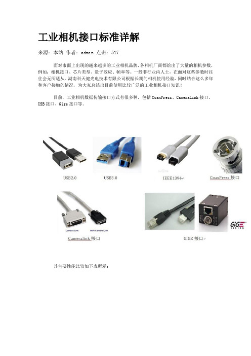
湖南科天健光电技术有限公司根据长期的相机使用经验,同时结合这么多年和客户接触的情况,为大家总结出目前使用比较广泛的工业相机接口知识!目前,工业相机数据传输接口方式有很多种,包括CoaxPress、CameraLink接口、USB接口、Gige接口等。
其主要性能比较如下表所示:USB2.0USB 即“Universal Serial Bus ”,中文名称为通用串行总线。
这是近几年逐步在PC 领域广为应用的新型接口技术。
USB2.0则可以达到速度480Mbps,并且可以向下兼容USB1.1。
这几年,随着大量支持USB的个人电脑的普及,USB逐步成为个人电脑的标准接口已经是大势所趋。
在主机端,最新推出的个人电脑几乎100%支持USB;而在外设端,使用USB接口的设备也与日俱增,例如数码相机、扫描仪、游戏杆、磁带和软驱、图像设备、打印机、键盘、鼠标等等。
2000年制定的USB 2.0标准是真正的USB 2.0,被称为USB 2.0的高速(High-speed)版本,理论传输速度为480 Mbps,即60 MB/s,但实际传输速度一般不超过30 MB/s,采用这种标准的USB设备也比较多。
USB电缆的长度在不加级连装置的情况下为小于5m。
USB3.0USB3.0 ——也被认为是SuperSpeedUSB——为那些与PC或音频/高频设备相连接的各种设备提供了一个标准接口。
只是个硬件设备,计算机内只有安装USB3.0相关的硬件设备后才可以使用USB3.0相关的功能!从键盘到高吞吐量磁盘驱动器,各种器件都能够采用这种低成本接口进行平稳运行的即插即用连接,用户基本不用花太多心思在上面。
新的USB 3.0在保持与USB 2.0的兼容性的同时,还提供了下面的几项增强功能:(1)极大提高了带宽——高达5Gbps全双工(USB2.0则为480Mbps半双工)(2)实现了更好的电源管理(3)能够使主机为器件提供更多的功率,从而实现USB——充电电池、LED照明和迷你风扇等应用。
带你认识相机上每一个接口
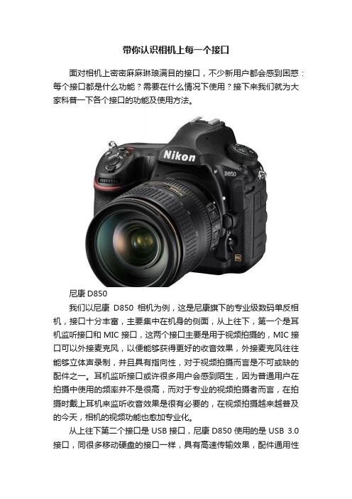
带你认识相机上每一个接口面对相机上密密麻麻琳琅满目的接口,不少新用户都会感到困惑:每个接口都是什么功能?需要在什么情况下使用?接下来我们就为大家科普一下各个接口的功能及使用方法。
尼康D850我们以尼康D850相机为例,这是尼康旗下的专业级数码单反相机,接口十分丰富,主要集中在机身的侧面,从上往下,第一个是耳机监听接口和MIC接口,这两个接口主要是用于视频拍摄的,MIC接口可以外接麦克风,以便能够获得更好的收音效果,外接麦克风往往能够立体声录制,并且具有指向性,对于视频拍摄而言是不可或缺的配件之一。
耳机监听接口或许很多用户会感到陌生,因为普通用户在拍摄中使用的频率并不是很高,而对于专业的视频拍摄者而言,在拍摄时戴上耳机来监听收音效果是很有必要的,在视频拍摄越来越普及的今天,相机的视频功能也愈加专业化。
从上往下第二个接口是USB接口,尼康D850使用的是USB 3.0接口,同很多移动硬盘的接口一样,具有高速传输效果,配件通用性也很强。
USB接口用途较广的场景便是在摄影棚内联机拍摄,通过加长的USB线将相机和电脑连接起来,每拍摄一张图片就能及时传输到电脑上以便于现场观看和修图师现场快修,同时联机拍摄还能使用电脑遥控相机拍摄,在大型摄影棚内拍摄例如汽车这样的大型静物时往往需要分层布光,这样的情况下相机是不可以移动的,而摄影师更重要的工作此时从按动快门变成了协调灯光,于是通过USB连接电脑遥控相机进行拍摄就成为了很好的选择。
在日常使用中,万一刚好没有读卡器,还能通过USB接口往电脑中传输照片,十分方便。
在相机固件升级的时候也离不开USB连接。
从上往下第三个接口是HDMI,对于拍摄照片的用户而言这个接口使用率确实不高,而对于视频拍摄用户来说这是十分重要的接口,使用HDMI接口可以使用外置监视器。
在阳光直射的环境下外置监视器会更加方便。
而如果是使用Z 6或者Z 7微单相机,通过HDMI接口可以连接外录设备,能够录制4:2:2 10bit的4K视频,获得更高的视频画质,同时HDMI接口能够连接直播传输设备,可以用于视频直播,主要针对现在十分火热的直播需求。
Matrox Pulsar DALSA CL-C3-1024A相机接口应用指南说明书
DALSA CL-C3-1024A May 29, 1996DALSA CL-C3-1024A May 29, 1996Cabling Requirements (Continued)•the connections between the OS1 20-pin dual row connector of the camera and the 68-pin SCSI-2 connector of the PULSAR/DIG/MOD are as follows:DALSA CL-C3-1024A PULSAR/DIG/MOD(20-pin dual row connector - OS1)(68-pin SCSI-2 connector)Pin name Pin no. Pin name Pin no.AD7+1→DATA7+10AD7−2→DATA7−44AD6+3→DATA6+11AD6−4→DATA6−45AD5+5→DATA5+13AD5−6→DATA5−47AD4+7→DATA4+14AD4−8→DATA4−48AD3+9→DATA3+15AD3−10→DATA3−49AD2+11→DATA2+16AD2−12→DATA2−50AD1+13→DATA1+19AD1−14→DATA1−53AD0+15→DATA0+20AD0−16→DATA0−54STROBE+17→CLKIN+29STROBE−18→CLIKIN−63LVAL+19→HSYNC+26LVAL−20→HSYNC−60•the connections between the OS2 20-pin dual row connector of the camera and the 68-pin SCSI-2 connector of the PULSAR/DIG/MOD are as follows:DALSA CL-C3-1024A PULSAR/DIG/MOD(20-pin dual row connector - OS2)(68-pin SCSI-2 connector)Pin name Pin no. Pin name Pin no.BD7+1→DATA15+2BD7−2→DATA15−36BD6+3→DATA14+3BD6−4→DATA14−37BD5+5→DATA13+4BD5−6→DATA13−38BD4+7→DATA12+5BD4−8→DATA12−39BD3+9→DATA11+6BD3−10→DATA11−40BD2+11→DATA10+7BD2−12→DATA10−41BD1+13→DATA9+8BD1−14→DATA9−42BD0+15→DATA8+9BD0−16→DATA8−43DALSA CL-C3-1024A 29/05/96DALSA CL-C3-1024A May 29, 1996DALSA CL-C3-1024A 29/05/96 When timer1 reaches the value set for CTRL_T1START, the EXPOSURE1 signal beingsent to the camera goes high. When timer1 reaches zero, the EXPOSURE1 signal goeslow. The EXPOSURE1 signal should be sent immediately to the camera upon arrival ofan external trigger signal to indicate that exposure should begin, thereforeCTRL_SET1CNT and CTRL_T1START must be set equal to each other; this isaccomplished by setting CTRL_SET1CNTL equal to CTRL_T1STARTL andCTRL_SET1CNTH equal to CTRL_T1STARTH. The Pulsar indicates to the camerathat exposure should stop by sending the EXPOSURE2 pulse. For a given setting ofCTRL_SET2CNT, which is the time set on the timer for EXPOSURE2 (timer2), the timeat which the EXPOSURE2 pulse is sent is controlled by CTRL_T2START, the width ofthe EXPOSURE2 pulse. Timer2 starts counting down from CTRL_SET2CNT; when itreaches the value set for CTRL_T2START, the EXPOSURE2 signal being sent to thecamera goes high. When timer2 reaches zero, the EXPOSURE2 signal goes low. Sinceboth timers start at the same time, the exposure time is then CTRL_SET2CNT −CTRL_T2START. Finally, it should be noted that the EXPOSURE1 pulse must remainhigh until the LVAL pulse goes low; therefore the time set on timer1 (CTRL_SET1CNT)must be greater than the exposure time, plus the maximum possible delay between theEXPOSURE2 pulse and the LVAL pulse, plus the width of the LVAL pulse (the linetransfer time). The maximum possible delay between the EXPOSURE2 pulse and theLVAL pulse is taken to be 8.9µs (64 pixel times at a clock rate of 7.159 MHz); the linetransfer time is 71.5µs (512 pixel times, since there are two outputs, at a clock rate of7.159 MHz).So to summarize:CTRL_T1START = CTRL_SET1CNT, i.e., CTRL_T1STARTL = CTRL_SET1CNTLand CTRL_T1STARTH = CTRL_SET1CNTH EXPOSURE TIME = CTRL_SET2CNT − CTRL_T2STARTCTRL_SET1CNT > exposure time + maximum delay between EXPOSURE2 andLVAL pulses (8.9µs or 64 pixels) + line transfer time (71.5µsor 512 pixels)Remember that each 16-bit register is split into a low byte and a high byte. These valuesmust be in pixels and must be set in hexadecimal; the value of each 16-bit register canvary between 0 (0000 in Hex) and 65 535 (FFFF in Hex). The default time set on timer1as well as the default width of the EXPOSURE1 pulse is 6400 pixels, which inhexadecimal is 1900 (Here the low byte corresponds to 0H and the high byte to 19H).The default time set on timer2 is 6144 pixels (1800H) and the default width of theEXPOSURE2 pulse is 256 pixels (100H). The default exposure time is therefore6144 − 256 = 5888 pixels, which at a clock rate of 7.159MHz corresponds to 0.82ms.The registers are set in the following way:CTRL_SET1CNTL0H CTRL_SET2CNTL0HCTRL_SET1CNTH19H CTRL_SET2CNTH18HCTRL_T1STARTL0H CTRL_T2STARTL0HCTRL_T1STARTH19H CTRL_T2STARTH1HDALSA CL-C3-1024AMay 29, 1996When computing the hardware registers, the following question may be asked: “Some registers have been manually edited. Ok to overwrite them all? (y/n)”. Answer “no” to this question and to all questions that follow.IMPORTANT! These instructions must be followed very carefully ; the only registers that should be modified are those mentioned above . Please consult Matrox Imaging Applications at (514) 822-6061 if assistance is required.•the maximum trigger rate is the reciprocal of the width of the EXPOSURE1 pulse, or in other words, it is the reciprocal of the sum of the exposure time and 80.4µs. This last number is the sum of the maximum delay between the EXPOSURE2 and LVAL pulses (taken to be 8.9µs) and the line transfer time (71.5µs). The default max trigger rate is 1.1kHz•an RS-422 external trigger input may also be used once the following connectionsbetween the 68-pin SCSI-2 connector of the PULSAR/DIG/MOD and the external trigger source are made:PULSAR/DIG/MODExternal trigger source (68-pin SCSI-2 connector)Pin name Pin no. Pin nameTRIGGER+27←“RS-422 TRIGGER+”TRIGGER-61←“RS-422 TRIGGER-”•use Matrox Intellicam in order to modify the DCF for an RS-422 external trigger input.Consult the Matrox Intellicam User Guide for more informationThe DCF(s) mentioned in this application note can be found on the MIL and MIL-Lite CD, or our FTP site ().The information furnished byMatrox Electronics System, Ltd. is believed to be accurate and reliable. Please verify all interface connections with camera documentation or manual.Contact your local sales representative or Matrox Sales office or Matrox Imaging Applications at 514-822-6061 for assistance.CorporateHeadquarters:Canada and U.S.A.Matrox Electronic Systems Ltd.1055 St.Regis Blvd.Dorval, Quebec, Canada H9P 2T4Tel: (514) 685-7230Fax: (514) 822-6273。
单反的hdmi标准
单反的hdmi标准单反相机是许多摄影爱好者和专业摄影师喜爱的相机类型之一。
它具有高画质、高清晰度的特点,可以满足用户对画质的苛刻要求。
而单反相机的HDMI标准更是备受关注,因为它可以让用户在拍摄过程中实时观看画面,进行拍摄参数调整,甚至进行远程控制。
本文将就单反相机的HDMI标准进行详细介绍,帮助用户更好地了解和应用这一功能。
HDMI是High Definition Multimedia Interface的缩写,即高清晰度多媒体接口。
它是一种数字化的视频和音频接口标准,可以传输高清晰度的视频和高品质的音频信号。
在单反相机中,HDMI接口可以将相机拍摄的画面实时传输到外部显示设备上,如电视、显示器等,让用户可以更清晰地观看到拍摄画面,进行实时调整和控制。
单反相机的HDMI标准通常分为两种类型,mini HDMI和micro HDMI。
它们分别对应着不同的接口大小,用户在选择连接线时需要根据自己相机的接口类型来选择合适的连接线。
一般来说,相机厂商会在产品说明书中明确说明相机的HDMI 接口类型,用户可以根据说明书来选择合适的连接线。
使用HDMI连接线将单反相机与外部显示设备连接后,用户可以在外部显示设备上清晰地观看到相机拍摄的画面。
这对于一些特殊拍摄场景来说尤为重要,比如在户外拍摄时,用户可以通过连接到平板电脑或显示器上,更清晰地观察画面细节,确保拍摄效果。
同时,对于一些需要远距离观察的拍摄场景,如野生动物摄影、体育比赛摄影等,用户也可以通过连接到大屏幕上,更清晰地观察画面,进行远程控制和拍摄。
除了实时观看画面外,HDMI接口还可以帮助用户进行拍摄参数的调整。
在连接到外部显示设备后,用户可以更清晰地观察画面的曝光、对焦等情况,及时调整相机的拍摄参数,确保拍摄效果。
这对于一些对画面要求较高的摄影爱好者和专业摄影师来说尤为重要,可以帮助他们更好地掌握拍摄过程,提高拍摄效率和质量。
总的来说,单反相机的HDMI标准在实时观看画面、远程控制、拍摄参数调整等方面都具有重要的应用意义。
Matrox Corona JAI CV-M70 相机接口应用说明说明书

Interfacing non-standard cameras to Matrox CoronaJAI CV-M70 March 22, 2000VIDEO RGBVIDEO RGBHDWENTRIG INPUTPIXEL CLOCKJAI CV-M70 March 22, 2000JAI CV-M70 March 22, 2000JAI CV-M70March 22, 2000•Connections between the 6-pin multi connector (RS-232C) of the camera and the 44-pin connector of the Matrox Corona are as follows:JAI CV-M70(6-pin multi connector) CORONA/_/E (44-pin connector) Pin name Pin no. Pin namePin no.CablingRequirements (continued)TRIGGER INPUT 05 ← EXP(1)38 WEN OUTPUT06→VSYNC_TTL32•Connections between the 12-pin multi connector (DC/Ext. Sync) of the camera and the 44-pin connector of the Matrox Corona are as follows:JAI CV-M70(12-pin multi connector) CORONA/_/E (44-pin connector)Pin namePin no. Pin name Pin no. EXTERNAL HD OUTPUT06→HSYNC_TTL02•Connections between the H/W trigger source and the 44-pin connector of the Matrox Corona are as follows:H/W Trigger Source CORONA/_/E (44-pin connector) Pin namePin no. Pin name Pin no.H/W TRIG Cable -- → OPTOTRIG+ 35GND --OPTOTRIG-34The DCF(s) mentioned in this application note can be found on the MIL and MIL-Lite CD, or our FTP site (). The information furnished by Matrox Electronics System, Ltd. is believed to be accurate and reliable. Please verify all interface connections with cameradocumentation or manual. Contact your local sales representative or Matrox Sales office or Matrox Imaging Applications at 514-822-6061 for assistance.Corporateheadquarters:Canada and U.S.A.Matrox Electronic Systems Ltd.1055 St. Regis Blvd. Dorval, Quebec H9P 2T4 CanadaTel: (514) 685-2630 Fax: (514) 822-6273。
千兆网工业相机之GigE接口介绍
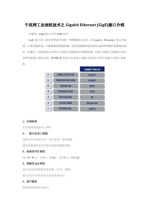
千兆网工业相机技术之Gigabit Ethernet (GigE)接口介绍关键词:GIge接口介绍,GIGE技术
GigE 接口是工业应用所新开发的一种图像接口技术,以Gigabit Ethernet 协议为标准,主要用做高速、大数据量的图像传输,远距离图像传输及降低远距离传输时电缆线的成本。
可通过一台控制单元对多台千兆网工业相机进行图像采集,目前千兆网工业相机已逐步代替其他接口成为主流,MV-EM\VE系列产品是基于该接口研发生产的中高端千兆网工业相机。
1、全球标准
在全球网络连接中占97%
2、独立全双工连接
连接之间无带宽共享,这不是第一流的链路
通过电缆或者光纤实现双向连续数据传输
3、较高的可扩展性
10/100 Mb/s, 1 Gb/s (GigE), 10 Gb/s (10GigE)
3、高级的QoS特性
适合对延时要求较高的传输(语音,视频)
核心协议可以扩展来支持高性能应用
4、高可靠性
错误控制和包重发能力。
Matrox Corona-II 相机接口应用说明(SENTECH STC-1100b)说明书
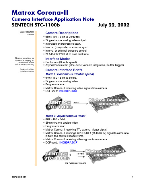
SENTECH STC-1100b July 22, 2002 Basics about thecameraCamera Descriptions§659 × 494 × 8-bit @ 30/60 fps.§Single channel analog video output.§Interlaced or progressive scan.§Internal (composite) or external sync.§Internal or external exposure control.§24.5454/12.2726 MHz pixel clock rate.Mode of operations as per Matrox Imaging (in parentheses as per camera manufacturer)Interface Modes§Continuous (Double speed)§Asynchronous reset (One-pulse Variable Integration Shutter Trigger)Basics about theinterface modesCamera Interface BriefsMode 1: Continuous (Double speed)§640 × 480 × 8-bit @ 60 fps.§Single channel analog video.§Progressive scan.§Matrox Corona-II receiving video signals from camera.§ DCF used:1100BDPC.DCFMode 2: Asynchronous Reset§640 × 480 × 8-bit.§Single channel analog video.§Progressive scan.§Matrox Corona-II receiving TTL external trigger signal.§Matrox Corona-II sending EXPOSURE1 (M-TRIG IN) signal to camera toinitiate and control exposure time.§Matrox Corona-II receiving video signals from camera.§ DCF used:1100BDPA.DCFSENTECH STC-1100b July 22, 2002Specifics about theinterface modesCabling details for theinterface modesSENTECH STC-1100b July 22, 2002Cabling details for theinterface modesThe DCF(s) mentioned in this application note can be found on the MIL CD or our FTP site (). The information furnished by MatroxElectronics System, Ltd. is believed to be accurate and reliable. Please verify all interface connections with camera documentation or manual. Contact your local sales representative or Matrox Sales office or Matrox Imaging Applications at 514-822-6061 for assistance.Corporate headquarters:Canada and U.S.A.Matrox Electronic Systems Ltd. 1055 St. Regis Blvd. Dorval, Quebec H9P 2T4 CanadaTel: (514) 685-2630 Fax: (514) 822-6273。
Matrox Helios eA XA 摄像头接口应用说明 SONY XC-HR70说明书
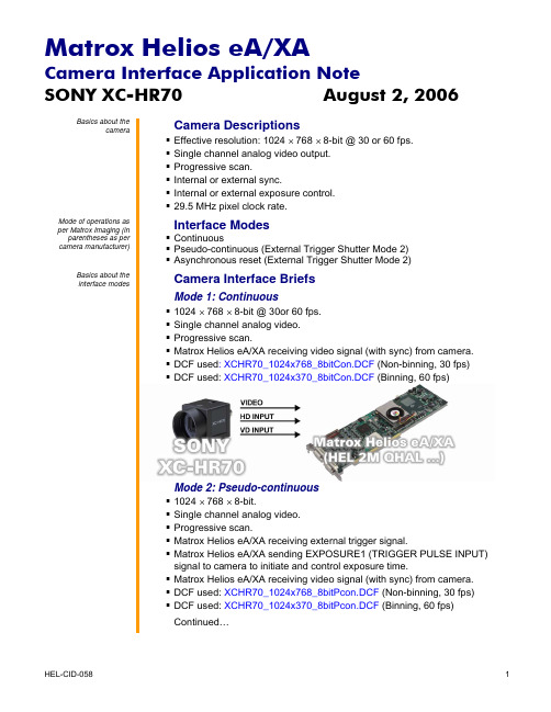
(12-pin connector)
Pin name
Pin no.
Pin name
Pin no.
CH0_INPUTA
C1
← VIDEO OUTPUT
04
P0_LVDS/TTL_CHSYNC_IO+
13
← HD
06
P0_LVDS/TTL_VSYNC_IO+
05
← VD
07
CH0_EXPOSURE
23
→ TRIG. PULSE INPUT 11
Camera Switch settings: Internal/External synchronization switch and DIP switches are set as follows, refer to the camera manual for additional information:
Camera Interface Application Note
SONY XC-HR70
August 2, 2006
Specifics about the interface modes
Camera Interface Details
Mode 1: Continuous
Camera Switch settings: Internal/External synchronization switch and DIP switches are set as follows, refer to the camera manual for additional information:
signal to camera to initiate and control exposure time. Matrox Helios eA/XA receiving video signal (with sync) from camera. DCF used: XCHR70_1024x768_8bitPcon.DCF (Non-binning, 30 fps) DCF used: XCHR70_1024x370_8bitPcon.DCF (Binning, 60 fps)
工业相机SDK接口设计说明书.doc
工业相机SDK 接口设计说明书目录1.简介 (3)1.1目标及范围 (3)1.2相关术语 (3)1.3参考资料 (3)2.分析设计 (5)2.1设计思想 (5)2.2接口结构 (5)2.3数据流分析 (6)3.接口描述(C++接口) (8)3.1传输层工厂类 (8)3.2设备控制类 (11)3.3G EN A PI (16)4.接口描述(C接口) (21)4.1相机控制通用接口 (21)4.2XML相关接口 (37)4.3G IG EV ISION相机特有的接口 (41)4.4U3V相机特有的接口 (43)5.数据结构描述 (44)5.1MV_GIGE_DEVICE_INFO(G IG E设备信息) (44)5.2MV_USB3_DEVICE_INFO(USB3设备信息) (45)5.3MV_CC_DEVICE_INFO(相机信息统一结构体) (45)5.4MV_FRAME_OUT_INFO(输出帧信息) (46)5.5MV_XML_NODE_FEATURE(XML节点基本信息) (47)6.修订记录 (48)1.简介1.1目标及范围本文档的目的是设计一套工业相机SDK的统一接口,兼容GigEVision、1394、U3V 和CameraLink等标准协议。
业务层软件可同时调用GenApi和这套接口,以实现对相机的控制。
当前版本仅支持GigEVision和U3V两种传输协议,所以主要根据《GigEVisionSDK产品需求规格说明书》和《USB3VisionSDK产品需求规格说明书》进行设计,今后会在此版本的基础上逐渐完善。
本文档的预期读者是项目经理、软件详细设计者、软件开发人员、测试人员和项目管理人员等。
1.2相关术语1.3参考资料1.《GigEVisionSDK产品需求规格说明书.doc》.2.《USB3VisionSDK产品需求规格说明书.doc》.3.《GenICam_Standard_v2_0.pdf》.4.eBUS SDK C++ API.chm.5.FlyCapture2 C Documentation.chm.6.FlyCapture2SDKHelp.chm7.JAI SDK.chm8.ImagingSource.chm.9.PylonCSDK.chm2.分析设计2.1设计思想工业相机SDK的设计首先考虑的是支持多个相机协议,提取共性后设计通用的接口和结构体,使得上层应用软件不需要关心具体的相机协议。
camera link接口标准
Camera Link是一种数字图像传输接口标准,用于连接相机和计算机。
它提
供了高速、可靠和实时的数据传输,适用于高速图像采集和处理应用。
Camera Link接口标准由三个部分组成:相机端接口、帧同步接口和计算机
端接口。
相机端接口包括一个或多个Camera Link接口连接器,用于传输图像数据和控制信号。
帧同步接口用于同步相机和计算机之间的数据传输。
计算机端接口包括一个或多个Camera Link接口连接器,用于接收图像数据和控制信号。
Camera Link接口标准支持多种数据传输模式,包括Base、Medium和Full。
Base模式提供最低的带宽和分辨率,适用于低成本和低分辨率应用。
Medium模式
提供中等的带宽和分辨率,适用于中等成本和中等分辨率应用。
Full模式提供最
高的带宽和分辨率,适用于高成本和高分辨率应用。
Camera Link接口标准还支持多种数据格式,包括8位、10位、12位和14位。
这些数据格式可以通过相机端接口进行设置,以满足不同应用的需求。
总之,Camera Link接口标准是一种高速、可靠和实时的数字图像传输接口,适用于高速图像采集和处理应用。
它提供了多种数据传输模式和数据格式,以满足不同应用的需求。
常见的相机输出接口
HDMI是High Definition Multimedia Interface的缩写,是数字高清多媒体接口。HDMI接口一开始主要应用于机顶盒、媒体播放机、电视机、摄像机输出等消费领域,因为HDMI兼容DVI接口,同时HDMI可以内嵌声音,所以HDMI接口应用越来越广泛,同时HDMI接口的连接器体积小,现在很多工业相机也开始使用HDMI作为信号输出口。HDMI 1.2的最大视频带宽为3.96 Gbps,这在工业相机应用比较广泛,但是在消费电子领域HDMI目前已经发展到2.0版本,最大视频带宽为14.4 Gbps,随着时间的发展,很多高速相机也会采用该接口作为图像输出口。HDMI接口的最大缺点就是紧固性不好,所以如果相机需要移动的话,容易导致信号接触不良。
CoaXPress该标准容许相机设备通过单根同轴电缆连接到主机,以高达6.25G比特/秒的速度传输数据,4根线缆可达25 Gbit/s.标准同轴电缆和带宽的采用,使得CoaXPress不仅可以引起机器视觉应用领域的兴趣,还适合广泛采用同轴电缆的医疗与安保市场的应用。
目前在视频会议领域CVBS、VGA、DVI、HDMI、SDI使用最广泛,在广播电视领域CVBS、HDMI、SDI使用最广泛,在安防领域CVBS、SDI使用最广泛,在上述3个领域,大部分领域都有图像采集存储的需求,这几个领域的图像主要都是满足娱乐、欣赏、监测等需求,所以图像经过压缩之后,大部分还能满足观看的需求,而图像一旦经过压缩,数据量将大幅减少,比如常见的1080P30的视频,经过H.264算法的压缩,码率一般能控制在8Mbps,亦即1MB/s量级,数据带宽很小,所以用常规的嵌入式主控芯片,ARM等即可实现存储的需求,如果并发路数很多,则只需要用高性能的ARM系统或者PC系统即可。
cameralink接口标准详细讲解

cameralink接口标准详细讲解一、概述Cameralink是一种用于连接相机和计算机的接口标准,它旨在提供一种简单、可靠、高效的连接方式,以便在计算机上使用各种类型的相机。
本篇文章将详细介绍Cameralink接口标准的基本概念、特点、应用场景以及与其他接口标准的比较。
二、基本概念Cameralink是一种基于USB接口的协议,它通过USBType-C接口与相机连接。
Cameralink支持高速数据传输,可以实时传输高质量的图像数据。
它还提供了一些额外的功能,如相机控制、音频传输等。
三、特点1.简单易用:Cameralink接口设计简单,易于连接和使用。
它只需要一个USBType-C接口,不需要额外的驱动程序或软件。
2.高速度:Cameralink支持高速数据传输,可以提供高分辨率、高质量的图像数据。
3.兼容性强:Cameralink可以兼容各种类型的相机,包括数码相机、摄像头、工业相机等。
4.扩展性强:Cameralink可以与其他设备或软件进行集成,如麦克风、灯光等,以满足不同的应用需求。
四、应用场景1.视频会议:Cameralink可以用于视频会议中,实时传输高质量的图像数据,使远程会议更加真实和生动。
2.无人驾驶:Cameralink可以用于无人驾驶汽车中,实时传输道路图像和周围环境信息,帮助汽车做出正确的决策。
3.工业检测:Cameralink可以用于工业检测中,实时传输产品图像,帮助工人快速发现问题并进行处理。
4.医疗影像:Cameralink可以用于医疗影像中,实时传输高清医学图像,为医生提供准确的诊断依据。
五、与其他接口标准的比较B接口:Cameralink是基于USB接口的协议,与传统的USB 接口相比,它具有更高的速度和更简单的连接方式。
2.HDMI接口:Cameralink与HDMI接口相比,它更适合于实时图像传输,可以提供更高质量的图像数据。
3.蓝牙接口:与蓝牙接口相比,Cameralink可以直接通过USB接口进行数据传输,不需要额外的设备或软件支持。
Matrox Solios eCL XCL 相机接口应用指南说明书

LORD Ingénierie DVLC2098K August 9, 2006 –Basics about thecameraCamera DescriptionsEffectiveresolution:Upto2098pixels/***************************.Camera Link BASE interface (8-bit RGB or 16-bit multiplexed).External and internal sync.External or internal exposure control.20/60 MHz pixel clock rate.Mode of operations as per Matrox Imaging (in parentheses as per camera manufacturer)Interface ModeFixed line scan rate (exposure control or continuous)Variable line scan rate (exposure control)Fixed line scan rate with frame trigger (exposure control or continuous)Variable line scan rate with frame trigger (exposure control)Fixed line scan rate with variable frame size (exposure control or continuous) Variable line scan rate with variable frame size (exposure control)Basics about theinterface modesCamera Interface BriefsMode 1: Fixed line scan rate2098 pixels/line.Camera Link BASE interface (8-bit RGB).DCF configured for 1000 lines per virtual frame.Matrox Solios eCL/XCL sending periodic EXPOSURE1 (CIEXT) signal tocamera.Matrox Solios eCL/XCL receiving LVAL, PIXEL CLOCK (CLK @ 20 MHz) andvideo data from camera.DCF used:DVLC2098k_2098_8bitRGBFLS.DCFLORD Ingénierie DVLC2098K August 9, 2006 Basics about theCamera Interface Briefs (cont.)interface modesMode 2: Variable line scan rate2098 pixels/line.Camera Link BASE interface (8-bit RGB).DCF configured for 1000 lines per virtual frame.Matrox Solios eCL/XCL receiving external TTL line trigger signal.Matrox Solios eCL/XCL sending EXPOSURE1 (CIEXT) signal to camera.Matrox Solios eCL/XCL receiving LVAL, PIXEL CLOCK (CLK @ 20 MHz)and video data from camera.DCF used: DVLC2098k_2098_8bitRGBVLS.DCFMode 3: Fixed line scan rate with frame trigger2098 pixels/line.Camera Link BASE interface (8-bit RGB).DCF configured for 1000 lines per virtual frame.Matrox Solios eCL/XCL receiving external TTL frame (virtual) trigger signal.Matrox Solios eCL/XCL sending periodic EXPOSURE1 (CIEXT) signal tocamera.Matrox Solios eCL/XCL receiving LVAL, PIXEL CLOCK (CLK @ 20 MHz)and video data from camera.DCF used: DVLC2098k_2098_8bitRGBFLSFT.DCFLORD Ingénierie DVLC2098K August 9, 2006 Basics about theCamera Interface Briefs (cont.)interface modesMode 4: Variable line scan rate with frame trigger2098 pixels/line.Camera Link BASE interface (8-bit RGB).DCF configured for 1000 lines per virtual frame.Matrox Solios eCL/XCL receiving external TTL frame (virtual) and line triggersignals.Matrox Solios eCL/XCL sending EXPOSURE1 (CIEXT) signal to camera.Matrox Solios eCL/XCL receiving LVAL, PIXEL CLOCK (CLK @ 20 MHz)and video data from camera.DCF used: DVLC2098k_2098_8bitRGBVLSFT.DCFMode 5: Fixed line scan rate with variable frame size2098 pixels/line.Camera Link BASE interface (8-bit RGB).DCF configured for 1000 lines per virtual frame.Matrox Solios eCL/XCL receiving external TTL frame (virtual) trigger signal.Matrox Solios eCL/XCL sending periodic EXPOSURE1 (CIEXT) signal tocamera.Matrox Solios eCL/XCL receiving LVAL, PIXEL CLOCK (CLK @ 20 MHz)and video data from camera.DCF used: DVLC2098k_2098_8bitRGBFLSVF.DCFLORD Ingénierie DVLC2098K August 9, 2006 Basics about theCamera Interface Briefs (cont.)interface modesMode 6: Variable line scan rate with variable frame size2098 pixels/line.Camera Link BASE interface (8-bit RGB).DCF configured for 1000 lines per virtual frame.Matrox Solios eCL/XCL receiving external TTL frame (virtual) and line triggersignals.Matrox Solios eCL/XCL sending EXPOSURE1 (CIEXT) signal to camera.Matrox Solios eCL/XCL receiving LVAL, PIXEL CLOCK (CLK @ 20 MHz)and video data from camera.DCF used: DVLC2098k_2098_8bitRGBVLSVF.DCFSpecifics about theCamera Interface Detailsinterface modesMode 1: Fixed line scan rateLine rate: The frequency of the periodic EXPOSURE1 (CIEXT) signaldetermines the camera’s line rate. The maximum line rate for this cameraequals 3.09 kHz.Exposure time: For exposure control mode the exposure time is theinactive (low level) period between the falling and rising edges of theEXPOSURE1 (CIEXT) signal. The default exposure time for this DCF is 150μs. Maximum/minimum exposure time per line for this DCF is 839 ms and 50ns respectively. The exposure time can be modified in the DCF using MatroxIntellicam or with the MIL MdigControl() function. Consult the respectivemanual for more information.Camera communication: This DCF will work with the continuous andexposure control modes. Set the mode via the Camera Linkcommunication. Refer to the camera manual for additional information.Menu Cmd Value FunctionUser settings U 00 or 20 Continuous or exposure control modeUser settings C 4 3 × 8-bits parallel @ 20 MHz eachLORD Ingénierie DVLC2098K August 9, 2006 Specifics about theCamera Interface Details (cont.)interface modesMode 1: Fixed line scan rate (cont.)Timing diagram:Mode 2: Variable line scan rateLine rate: The line rate is controlled by the frequency of the external TTL linetrigger signal. The line trigger signal period must be larger than the totalduration of the exposure time (low level duration of the timer), the internaldelay of the camera (≈4.4 μs) and the line read out (104.9 μs).Exposure time: Refer to Mode 1: Fixed line scan rate.Camera communication: This DCF will work with exposure control modeonly. Set the mode via the Camera Link communication. Refer to the cameramanual for additional information.Menu Cmd Value FunctionUser settings U 20 Exposure control modeUser settings C 4 3 × 8-bits parallel @ 20 MHz eachTiming diagram:LORD Ingénierie DVLC2098K August 9, 2006 Specifics about theCamera Interface Details (cont.)interface modesMode 3: Fixed line scan rate with frame triggerLine/frame rate: The line rate is fixed and controlled by the frequency ofEXPOSURE1 (CIEXT) signal. The default exposure time for this DCF is 150μs (for exposure control mode). The virtual frame rate is variable andcontrolled by the period of the external frame trigger signal, however theexternal frame trigger period must always be greater than the total time of thenumber of lines captured. The number of lines per virtual frame (maximum of1000 for this DCF) is fixed and controlled by the vertical timing of the DCF.Capture of the lines will start with the rising edge of the frame trigger signal.Exposure time: Refer to Mode 1: Fixed line scan rate.C amera communication: Refer to Mode 1: Fixed line scan rate.Timing diagram:Mode 4: Variable line scan rate with frame triggerLine/frame rate: The line rate is controlled by the frequency of the externalTTL line trigger signal. The line trigger signal period must be larger than thetotal duration of the exposure time (low level duration of the timer), theinternal delay of the camera (≈4.4 μs) and the line read out (104.9 μs). Thedefault exposure time for this DCF is 150 μs. The virtual frame rate isvariable and controlled by the period of the external frame trigger signal,however the external trigger period must always be greater than the totaltime of the number of lines captured. The number of lines per virtual frame(1000 for this DCF) is fixed and controlled by the vertical timing of the DCF.Capture of the lines will start with the rising edge of the frame trigger signal.Exposure time: Refer to Mode 1: Fixed line scan rate.Camera communication:Refer to Mode 2: Variable line scan rate.Continued.…LORD Ingénierie DVLC2098K August 9, 2006 Specifics about theCamera Interface Details (cont.)interface modesMode 4: Variable line scan rate with frame triggerTiming diagram:Mode 5: Fixed line scan rate with variable frame sizeLine/frame rate: The line rate is fixed and controlled by the frequency ofEXPOSURE1 (CIEXT) signal. The default exposure time for this DCF is 150μs (for exposure control mode). The number of lines per virtual frame(maximum of 1000 for this DCF) is variable and controlled by the frametrigger signal. Matrox Solios eCL/XCL captures lines during the high level ofthe frame trigger signal. To modify the maximum amount of lines captured,change the active vertical timing period in the DCF. Capture of the lines willstart with the rising edge of the frame trigger signal.Exposure time: Refer to Mode 1: Fixed line scan rate.Camera communication:Refer to Mode 1: Fixed line scan rate.Timing diagram:LORD Ingénierie DVLC2098K August 9, 2006 Specifics about theCamera Interface Details (cont.)interface modesMode 6: Variable line scan rate with variable frame sizeLine/frame rate: The line rate is variable and controlled by the external linetrigger frequency. The default exposure time for this DCF is 150 μs. Thenumber of lines per virtual frame (maximum of 1000 for this DCF) is variableand controlled by the frame trigger signal. Matrox Solios eCL/XCL captureslines during the high level of the frame trigger signal. To modify the maximumamount of lines captured, change the active vertical timing period in the DCF.Capture of the lines will start with the rising edge of the frame trigger signal.Exposure time: Refer to Mode 1: Fixed line scan rate.Camera communication:Refer to Mode 2: Variable line scan rate.Timing diagram:Cabling details for theCabling Requirementsinterface modesMode 1: Fixed line scan rateCable and Connection: Standard Camera Link cable.Mode 2: Variable line scan rateCable and Connection: Standard Camera Link.External trigger: External line trigger should be connected to the OPTOTRIG input of the 9-pin connector (pins 7 and 2) on the External I/O adapterbracket:EXTERNAL I/O BRACKET(9-pin connector) External Trigger SourcePin Name Pin no. Pin NameOPTO_AUX_IN0 + 07 ←LINE TRIGGER (TTL FORMAT)OPTO_AUX_IN0 - 02 ←LINE TRIGGER (GROUND)LORD Ingénierie DVLC2098K August 9, 2006 Specifics about theCabling Requirementsinterface modesMode 3: Fixed line scan rate with frame triggerCable and Connection: Standard Camera Link.External trigger: External line trigger should be connected to the OPTOTRIG input of the 9-pin connector (pins 4 and 5) on the External I/O adapterbracket:EXTERNAL I/O BRACKET(9-pin connector) External Trigger SourcePin Name Pin no. Pin NameOPTO_AUX_IN1 + 04 ←FRAME TRIGGER (TTL FORMAT)OPTO_AUX_IN1 - 05 ←FRAME TRIGGER (GROUND)Mode 4: Variable line scan rate with frame triggerCable and Connection: Standard Camera Link.External trigger: External frame and line triggers should be connected to theOPTO TRIG inputs of the 9-pin connector on the External I/O adapterbracket:EXTERNAL I/O BRACKET(9-pin connector) External Trigger SourcesPin name Pin no. Pin nameOPTO_AUX_IN1 + 04 ←FRAME TRIGGER (TTL FORMAT)OPTO_AUX_IN1 - 05 ←FRAME TRIGGER (GROUND)OPTO_AUX_IN0 + 07 ←LINE TRIGGER (TTL FORMAT)OPTO_AUX_IN0 - 02 ←LINE TRIGGER (GROUND)Mode 5: Fixed line scan rate with variable frame sizeCable and Connection: Standard Camera Link.External trigger: External trigger should be connected to the OPTO TRIGinput (pins 4 and 5) of the 9-pin connector on the External I/O adapterbracket:EXTERNAL I/O BRACKET(9-pin connector) External Trigger SourcesPin name Pin no. Pin nameOPTO_AUX_IN1 + 04 ←FRAME TRIGGER (TTL FORMAT)OPTO_AUX_IN1 - 05 ←FRAME TRIGGER (GROUND)LORD Ingénierie DVLC2098K August 9, 2006 Cabling details for theCabling Requirementsinterface modesMode 6: Variable line scan rate with variable frame size▪Cable and Connection: Standard Camera Link.▪External trigger: External frame and line triggers should be connected to theOPTO TRIG inputs of the 9-pin connector on the External I/O adapterbracket:EXTERNAL I/O BRACKET(9-pin connector) External Trigger SourcesPin name Pin no. Pin nameOPTO_AUX_IN1 + 04 ←FRAME TRIGGER (TTL FORMAT)OPTO_AUX_IN1 - 05 ←FRAME TRIGGER (GROUND)OPTO_AUX_IN0 + 07 ←LINE TRIGGER (TTL FORMAT)OPTO_AUX_IN0 - 02 ←LINE TRIGGER (GROUND)The DCFs mentioned in this application note are also attached (embedded) to this PDF file – use the Adobe Reader’s View File Attachment to access the DCF files. The information furnished by Matrox Electronics System, Ltd. is believed to be accurate and reliable. Please verify all interface connections with camera documentation or manual. Contact your local sales representative or Matrox Sales office or Matrox Imaging Applications at 514-822-6061 for assistance. © Matrox Electronic Systems Ltd, 2006-2011.Matrox Electronic Systems Ltd.1055 St. Regis Blvd.Dorval, Quebec H9P 2T4CanadaTel: (514) 685-2630Fax: (514) 822-6273。
Matrox Odyssey Xpro 相机接口应用说明文档(Photonfocus MV-D640

Photonfocus MV-D640-66-CL-10 March 16, 2006 Basics about thecameraCamera DescriptionsEffective resolution: 640 × 480 × 10-bit @ 200 fps.Camera Link BASE interface (10-bit, dual tap).Progressive scan.Internal sync.Internal exposure control.66 MHz pixel clock rate.Mode of operations as per Matrox Imaging (in parentheses as per camera manufacturer)Interface ModeContinuous (Free Running) Pseudo-continuous (Trigger) Asynchronous reset (Trigger)Basics about theinterface modesCamera Interface BriefsMode 1: Continuous640 × 480 × 10-bit @ 200 fps.Camera Link BASE interface (10-bit, dual tap).Matrox Odyssey Xpro receiving LVAL, FVAL, PIXEL CLOCK (CLK @ 66MHz) and video from camera.DCF used: MV-D640-66-CL-10_640x480_10bitCon.DCFMode 2: Pseudo-continuous640 × 480 × 10-bit.Camera Link BASE interface (10-bit, dual tap).Matrox Odyssey Xpro sending EXPOSURE1 (CC1) signal to camera toinitiate the exposure.Matrox Odyssey Xpro receiving LVAL, FVAL, PIXEL CLOCK (CLK @ 66MHz) and video from camera.DCF used: MV-D640-66-CL-10_640x480_10bitPcon.DCFContinued…Photonfocus MV-D640-66-CL-10 March 16, 2006 Basics about theCamera Interface Briefs (cont.)interface modesMode 2: Pseudo-continuousMode 3: Asynchronous reset640 × 480 × 10-bit.Camera Link BASE interface (10-bit, dual tap).Matrox Odyssey Xpro receiving external trigger signal.Matrox Odyssey Xpro sending EXPOSURE1 (CC1) signal to camera toinitiate the exposure.Matrox Odyssey Xpro receiving LDV, FDV, CLK and video from camera.DCF used: MV-D640-66-CL-10_640x480_10bitAsync.DCFPhotonfocus MV-D640-66-CL-10 March 16, 2006 Specifics about theCamera Interface Detailsinterface modesMode 1: ContinuousFrame rate: Matrox Odyssey Xpro receives the continuous video fromthe camera at 200 frames per second . To increase the frame rate,reduce exposure time in the PhotonFocus PFRemote CameraConfiguration utility (PFRemote.EXE).Exposure time: Exposure time is determined by the Exposure TimeField setting in the PFRemote utility. Refer to the camera manual formore information.Camera settings: The camera mode is set to the following setting in thePFRemote utility. Refer to the camera manual for more information.Mode SettingTrigger Free RunningOutput 10-bitSpecial clock FAST 66 MHzMode 2: Pseudo-continuousFrame rate: The frame rate is determined by the frequency of theEXPOSURE1 (CC1) signal.Exposure time: The rising edge of the EXPOSURE1 (CC1) signalinitiates the camera’s internal exposure time. To modify the exposuretime, change the Exposure Time Field setting in the PFRemote utility.Refer to the camera manual for more information.Camera settings: The camera mode is set to the following setting in thePFRemote utility. Refer to the camera manual for more information.Mode SettingTrigger External TriggerOutput 10-bitSpecial clock FAST 66 MHzMode 3: Asynchronous ResetFrame rate: The frame rate is determined by the frequency of theexternal trigger signal. The period between the external trigger signalsmust be larger than the frame readout period and the exposure time.Exposure time: The rising edge of the EXPOSURE1 (CC1) signalinitiates the camera’s internal exposure time. To modify the exposuretime, change the Exposure Time Field setting in the PFRemote utility.Refer to the camera manual for more information.Camera settings: Refer to Mode 2: Pseudo-continuous.Photonfocus MV-D640-66-CL-10 March 16, 2006 Cabling details for theCabling Requirementsinterface modesMode 1 and 2: Continuous and Pseudo-continous▪Cable and Connection: Standard Camera Link cable.Mode 2: Asynchronous reset▪Cable and Connection: Standard Camera Link.▪External trigger: External trigger should be connected to the OPTOTRIG input of the 9-pin connector (pins 7 and 2) on the Expanded I/Oadapter bracket.EXPANDED I/O BRACKET(9-pin connector) External Trigger SourceOPTOTRIG + 07 ←SIGNAL --OPTOTRIG - 02 ←GROUND --The DCFs mentioned in this application note are also attached (embedded) to this PDF file – use the Adobe Reader’s View File Attachment to access the DCF files. The information furnished by Matrox Electronics System, Ltd. is believed to be accurate and reliable. Please verify all interface connections with camera documentation or manual. Contact your local sales representative or Matrox Sales office or Matrox Imaging Applications at 514-822-6061 for assistance. © Matrox Electronic Systems Ltd, 2006-2011.Matrox Electronic Systems Ltd.1055 St. Regis Blvd.Dorval, Quebec H9P 2T4CanadaTel: (514) 685-2630Fax: (514) 822-6273。
Matrox Radient eCL 相机接口应用说明书
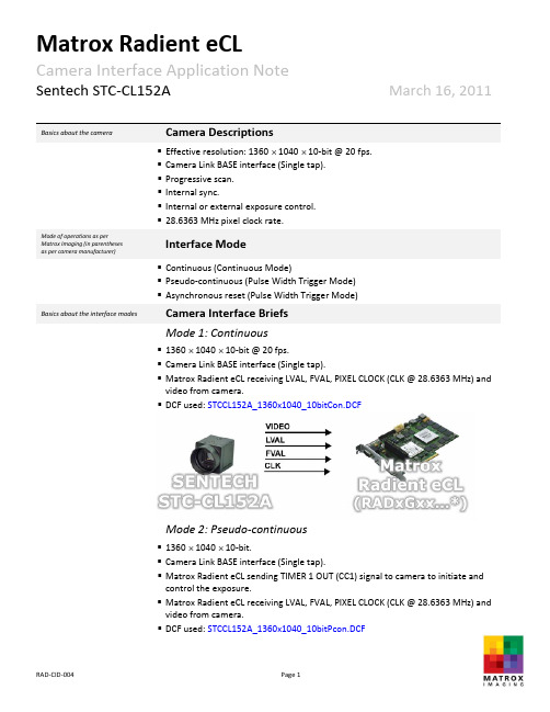
Sentech STC‐CL152A March 16, 20110041Basics about the camera Camera Descriptions▪Effective resolution: 1360 ⨯ 1040 ⨯ 10‐bit @ 20 fps. ▪Camera Link BASE interface (Single tap).▪Progressive scan.▪Internal sync.▪Internal or external exposure control.▪28.6363 MHz pixel clock rate.Mode of operations as perMatrox Imaging (in parenthesesas per camera manufacturer)Interface Mode▪Continuous (Continuous Mode)▪Pseudo‐continuous (Pulse Width Trigger Mode) ▪Asynchronous reset (Pulse Width Trigger Mode)Basics about the interface modes Camera Interface Briefs Mode 1: Continuous▪1360 ⨯ 1040 ⨯ 10‐bit @ 20 fps.▪Camera Link BASE interface (Single tap).▪Matrox Radient eCL receiving LVAL, FVAL, PIXEL CLOCK (CLK @ 28.6363 MHz) and video from camera.▪DCF used: STCCL152A_1360x1040_10bitCon.DCFMode 2: Pseudo‐continuous▪1360 ⨯ 1040 ⨯ 10‐bit.▪Camera Link BASE interface (Single tap).▪Matrox Radient eCL sending TIMER 1 OUT (CC1) signal to camera to initiate andcontrol the exposure.▪Matrox Radient eCL receiving LVAL, FVAL, PIXELCLOCK (CLK @ 28.6363 MHz) and video from camera.▪DCF used: STCCL152A_1360x1040_10bitPcon.DCFSentech STC‐CL152A March 16, 20110042Basics about the interface modes Camera Interface Briefs (cont.) Mode 2: Pseudo‐continuousMode 3: Asynchronous reset▪1360 ⨯ 1040 ⨯ 10‐bit.▪Camera Link BASE interface (Single tap).▪Matrox Radient eCL receiving external trigger signal.▪Matrox Radient eCL sending TIMER 1 OUT (CC1) signal to camera to initiate and control the exposure.▪Matrox Radient eCL receiving LVAL, FVAL, PIXEL CLOCK (CLK @ 28.6363 MHz) and video from camera.▪DCF used: STCCL152A_1360x1040_10bitAsync.DCFSpecifics about the interface modes Camera Interface DetailsMode 1: Continuous▪Frame rate: Matrox Radient eCL receives the continuous video from the camera at 20 frames per second.▪Exposure time: Exposure time is set using the integration time setting in theCameraConfiguration utility. Refer to the camera manual for more information.Sentech STC‐CL152A March 16, 20110043Specifics about the interface modes Camera Interface Details (cont.) Mode 1: Continuous▪Camera control settings: Set the camera using the Sentech SOF‐Cube Camera Configuration Utility as follows: Trigger Mode = Normal | Output Mode = 10‐bitMode 2: Pseudo‐continuous▪Frame rate: The frame rate is determined by the frequency of the TIMER1 OUT (CC1) signal.▪Exposure time: The TIMER1 OUT (CC1) signal’s active duration initiates and controls the exposure time, which can be modified in the DCF using Matrox Intellicam or with the MIL MdigControl() function. Consult the respective manual for more information.▪Camera control settings: Set the camera using the Sentech SOF‐Cube Camera Configuration Utility as follows: Trigger Mode = Pulse Width Trigger | Output Mode = 10‐bit | Trigger Reset Mode = V‐ResetMode 3: Asynchronous Reset▪Frame rate: The frame rate is determined by the frequency of the external trigger signal. The period between the external trigger signals must be larger than the frame readout period plus the exposure time.▪Exposure time: Refer to Mode 2: Pseudo‐continuous.▪Camera settings: Refer to Mode 2: Pseudo‐continuous.Cabling details for the interfacemodesCabling RequirementsMode 1 and 2: Continuous and Pseudo‐continuous ▪Cable and Connection: One Mini‐To‐Mini Camera Link cable.Sentech STC‐CL152A March 16, 20110044Cabling details for the interfacemodesCabling Requirements (cont.) Mode 3: Asynchronous Reset▪Cable and Connection: One Mini‐To‐Mini Camera Link cable.▪External trigger: External trigger should be connected to the external auxiliary I/O (connector A on Matrox Radient eCL bracket).EXTERNAL AUX. I/O(connector A) External Trigger SourcePIN NAME PIN NO. PIN NAME PIN NO.OPTO_AUX_IN0 + 15 ← SIGNAL ‐‐OPTO_AUX_IN0 ‐ 09 ← GROUND ‐‐The DCFs mentioned in this application note are also attached (embedded) to this PDF file – use the Adobe Reader’s View File Attachment to access the DCF files. The information furnished by Matrox Electronics System, Ltd. is believed to be accurate and reliable. Please verify all interface connections with camera documentation or manual. Contact your local sales representative or Matrox Sales office or Matrox Imaging Applications at 514‐822‐6061 for assistance. © Matrox Electronic Systems Ltd, 2010‐2011.Matrox Electronic Systems Ltd.1055 St. Regis Blvd.Dorval, Quebec H9P 2T4CanadaTel: (514) 685‐2630Fax: (514) 822‐6273。
Matrox Solios eCL XCL相机接口应用指南说明书
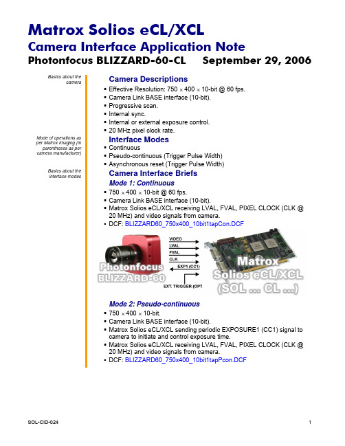
Photonfocus BLIZZARD-60-CL September 29, 2006 Basics about thecameraCamera DescriptionsEffective Resolution: 750 × 400 × 10-bit @ 60 fps.Camera Link BASE interface (10-bit).Progressive scan.Internal sync.Internal or external exposure control.20 MHz pixel clock rate.Mode of operations as per Matrox Imaging (in parentheses as per camera manufacturer)Interface ModesContinuousPseudo-continuous (Trigger Pulse Width) Asynchronous reset (Trigger Pulse Width)Basics about theinterface modesCamera Interface BriefsMode 1: Continuous750 × 400 × 10-bit @ 60 fps.Camera Link BASE interface (10-bit).Matrox Solios eCL/XCL receiving LVAL, FVAL, PIXEL CLOCK (CLK @20 MHz) and video signals from camera.DCF: BLIZZARD60_750x400_10bit1tapCon.DCFMode 2: Pseudo-continuous750 × 400 × 10-bit.Camera Link BASE interface (10-bit).Matrox Solios eCL/XCL sending periodic EXPOSURE1 (CC1) signal tocamera to initiate and control exposure time.Matrox Solios eCL/XCL receiving LVAL, FVAL, PIXEL CLOCK (CLK @20 MHz) and video signals from camera.DCF: BLIZZARD60_750x400_10bit1tapPcon.DCFPhotonfocus BLIZZARD-60-CL September 29, 2006 Basics about theCamera Interface Briefs (continued)interface modesMode 2: Pseudo-continuousMode 3: Asynchronous reset750 × 400 × 10-bit.Camera Link BASE interface (10-bit).Progressive scan.Matrox Solios eCL/XCL receiving external OPTO trigger signal.Matrox Solios eCL/XCL sending EXPOSURE1 (CC1) signal to camera toinitiate and control exposure time.Matrox Solios eCL/XCL receiving LVAL, FVAL, PIXEL CLOCK (CLK @20 MHz) and video signals from camera.DCF used: BLIZZARD60_750x400_10bit1tapAsync.DCFSpecifics about theCamera Interface Detailsinterface modesMode 1: ContinuousFrame Rate: With this DCF, the Matrox Solios eCL/XCL receives thecontinuous video from the camera at 20 frames per second.Exposure time: Exposure time is determined by the shutter setting.Refer to the camera manual for more information.Photonfocus BLIZZARD-60-CL September 29, 2006 Specifics about theCamera Interface Details (cont.)interface modesMode 1: ContinuousCamera Control: Set the camera mode to Free Run using thePFRemote utility. Refer to the camera manual for the commanddescriptions.Mode 2: Pseudo-continuousFrame Rate: With this DCF, the Matrox Solios eCL/XCL receives thepseudo-continuous video from the camera.Frame rate is controlled bythe frequency of the EXPOSURE1 (CC1) signal.Exposure time: The width (rising edge to falling edge) of theEXPOSURE1 (CC1) signal is the exposure time. To modify the exposuretime, change the active duration of Timer1 in Matrox Intellicam or with theMIL MdigControl() function. It is recommended that the total period(active and inactive) of Timer1 be set to greater than one frame duration.Furthermore, any increase or decrease to the exposure time willrespectively decrease or increase the frame rate.Camera Control: Set the camera mode to External Trigger using thePFRemote utility. Refer to the camera manual for the commanddescriptions.Mode 3: Asynchronous ResetFrame rate: The frame rate is determined by the frequency of theexternal trigger signal. The period between external trigger signals mustbe larger than the total duration of one frame.Exposure time: The width (rising edge to falling edge) of theEXPOSURE1 (CC1) signal is the exposure time. To modify the exposuretime, change the pulse duration of Timer1 in Matrox Intellicam or with theMIL MdigControl() function. Refer to the respective manual for moreinformation.Camera Control: Set the camera mode to External Trigger using thePFRemote utility. Refer to the camera manual for the commanddescriptions.Photonfocus BLIZZARD-60-CL September 29, 2006 Cabling details for theCabling Requirementsinterface modesMode 1 and 2: Continuous and Pseudo-continuous▪Cable and Connection: Standard Camera Link cable.Mode 3: Asynchronous reset▪Cable and Connection: Standard Camera Link.▪External trigger: External trigger should be connected to the OPTOTRIG input of the 9-pin connector (pins 7 and 2) on the Expanded I/Oadapter bracket.EXPANDED I/O BRACKET(9-pin connector) External Trigger SourceOPTOTRIG + 07 ←SIGNAL --OPTOTRIG - 02 ←GROUND --The DCFs mentioned in this application note are also attached (embedded) to this PDF file – use the Adobe Reader’s View File Attachment to access the DCF files. The information furnished by Matrox Electronics System, Ltd. is believed to be accurate and reliable. Please verify all interface connections with camera documentation or manual. Contact your local sales representative or Matrox Sales office or Matrox Imaging Applications at 514-822-6061 for assistance. © Matrox Electronic Systems Ltd, 2006-2011.Matrox Electronic Systems Ltd.1055 St. Regis Blvd.Dorval, Quebec H9P 2T4CanadaTel: (514) 685-2630Fax: (514) 822-6273。
Matrox Odyssey eCL XCL相机接口应用说明书

Cabling Requirements
Modes 1 and 2: Continuous, Pseudo-continuous Cable and Connection: Two MDR26 Camera Link cables.
Mode 3: Asynchronous reset
Cable and Connection: Two MDR26 Camera Link cables. External trigger: External trigger should be connected to the OPTO TRIG
Interface Mode
Continuous Pseudo-con tinuous Asynchronous reset (EXSYNC Level-controlled)
Camera Interface Briefs
Mode 1: uous
1280 × 1024 × 8-bit @ 500 fps. Camera Link FULL interface (Ten taps). Progressive scan. Matrox Odyssey eCL/XCL receiving LVAL, FVAL, PCLK and video from
LINE SIGNAL
--
OPTOTRIG -
02
LINE GROUND
--
The DCFs mentioned in this application note are also attached (embedded) to this PDF file – use the Adobe Reader’s View File Attachment to access the DCF files. The information furnished by Matrox Electronics System, Ltd. is believed to be accurate and reliable. Please verify all interface connections with camera documentation or manual. Contact your local sales representative or Matrox Sales office or Matrox Imaging Applications at 514-822-6061 for assistance. © Matrox Electronic Systems Ltd, 2008-2011.
- 1、下载文档前请自行甄别文档内容的完整性,平台不提供额外的编辑、内容补充、找答案等附加服务。
- 2、"仅部分预览"的文档,不可在线预览部分如存在完整性等问题,可反馈申请退款(可完整预览的文档不适用该条件!)。
- 3、如文档侵犯您的权益,请联系客服反馈,我们会尽快为您处理(人工客服工作时间:9:00-18:30)。
相机:Cognex工业相机
Cognex工业相机在BMW项目的M1SB090工位用来检测发动机活塞及连杆的装配情况。
活塞的检测,需要读出活塞上二维码的值,有OK和NG逻辑结果。
对于OK的结果,还需要反馈出活塞上的二维码的准确值。
连杆的检测,需要判断每个连杆是否装反,对于各种型号,如G7,G8,H7,H8等都能够判断出来。
相机工作过程:首先照相机读取发动机的活塞二维码信息,与活塞预装线的信息进行比较,若比较一致,再进行检测发动机的连杆的装配情况。
若一致,则认为活塞装配校验成功。
1.相机的硬件说明
相机的控制器是由小型的工业PC机组成。
控制器需要安装VisionPro(视觉检测软件)对相机进行数据的采样和PLC的数据通讯。
2.相机的组态
相机的PC机通过CP 343-1 Lean与西门子PLC进行通讯。
在配置CP网卡时要注意,IP地址要与PLC的网段要一致。
3.相机的通讯接口
相机发送的数据接口:
相机接收的数据接口:
工作时序图:
主要数据:
PLC控制的主要数据:
TypeNumber:机型号设定,表示发动机类型。
StepNumber:工序号设定,表示工序类别,1:活塞;2:连杆PositinNumber:位置号,对于四个相机,需要提供位置号。
Trigger:用于触发相机拍摄的控制位。
ResetResult:清除接口数据
相机反馈的主要数据:
相应相机会反馈基本信息,向PLC进行确认:TypeNumber:机型号设定,表示发动机类型。
StepNumber:工序号设定,表示工序类别,1:活塞;2:连杆PositinNumber:位置号,对于四个相机,需要提供位置号。
SysHeart:表示相机的通讯心跳。
SysFault:表示相机出现系统错误。
ActionFinished:表示拍摄完成。
LoadingJobStatus:表示正在装置发动机的状态信息。
Camera1ResultOK:表示相机1拍摄结果合格。
Camera2ResultOK:表示相机2拍摄结果合格。
Camera3ResultOK:表示相机3拍摄结果合格。
Camera4ResultOK:表示相机4拍摄结果合格。
Camera1ResultNG:表示相机1拍摄结果不合格。
Camera2ResultNG:表示相机2拍摄结果不合格。
Camera3ResultNG:表示相机3拍摄结果不合格。
Camera4ResultNG:表示相机4拍摄结果不合格。
ConrodResultAllOK:表示连杆的拍摄结果全合格。
ConrodResultAllNOK:表示连杆的拍摄结果不完全合格。
4.程序简述
功能块:
程序中将四个活塞检测分成四个job,将四个连杆检测分成另外四个job。
1)检测位置状态。
程序中有两个位置状态,分别为活塞检测位
置状态和连杆检测位置状态,分别为一系列传感器及记忆点组成。
只有在这两个位置状态照相机才能进行工作。
2)工序号的设定,活塞检测和连杆检测为两个不同的检测方式,
需要区分工序号。
在润滑完成后,相机准备就绪且在活塞位置状态下,将选择活塞检测工序,而选择连杆检测工序需在连杆位置状态且活塞检测任务已完成的情况下。
3)装载任务。
装载检测需要的一些信息,为触发检测作准备。
装载的一些重要条件有:与预装线的信息匹配成功或预装线已屏蔽,润滑结束,相机准备就绪,工序号已设定且在相应的检测位置状态。
按下启动按钮后,相机将装载相应信息并将光源打开。
4)触发相机进行检测。
将装载任务结束后,相机将被触发进行
活塞或连杆的检测。
检测结束后将反馈回相应的检测信息结果,在PC677的工位总览页面及相机结果页面显示出来。
5)相机检测不合格情况。
若有个别相机检测不合格,将错误信
息提示复位掉,同时将清除相机的检测信息,按下启动按钮后,将对不合格的重新进行任务装载及相机检测。
5.注意事项
1)若相机检测活塞不合格,一是相机不能读出二维码,此时需
要稍微调整相机位置或活塞位置,二是相机能读出二维码,却出现不合格信息,切换到相机结果页面,认真比对相机拍摄结果信息与预装线发送的信息,此时可能是活塞安装缸的位置错误。
2)若相机检测连杆不合格,需要稍微调整连杆的位置,使相机
处于最佳检测位置。
