ICAO Annex14
民用机场飞行区技术标准

在国际民nex 14)中,规定了民用机场飞行区的技术标准。这些标准包括飞行区内的地面标志、导航设施、通信设备、能见度要求、照明设备等。
根据ICAO的规定,民用机场的飞行区应具有足够的宽度和长度,以满足不同类型的飞机的起飞和着陆要求。此外,飞行区的地面应平整、稳定,并具有足够的承载能力。飞行区内的导航设施、通信设备和照明设备应符合ICAO的规定,以保证飞行的安全性。
机场滑行引导标记牌培训教程

滑行引导标记牌中国民用航空局机场司马志刚caacma@2008年10月滑行引导标记牌滑行引导标记牌•传达飞机或车辆必须停住等待塔台放行的信息;•传达禁止进入某一地区的信息;•帮助驾驶员识别其所在位置;•帮助驾驶员识别滑行道交叉或分支点前方滑行道的代号;•向驾驶员指明前往目的地的方向;•帮助驾驶员判断其飞机是否已脱离跑道。
滑行引导标记牌包括指令性标记牌左侧的标记牌设在Mandatory Instruction SignsFigure 5-30 ICAO 5.4.2.2 –Mandatory instruction signs shall include runway designation signs, category I, II or III holding position signs,runway-holding position signs, road-holding position signs and NO ENTRY signs.Mandatory Instruction SignsB115R -33L15R -33L33L CAT IIIB2{Runway designation sign on a taxiway Runway designation sign on a runway Category III holding position signRunway-holding position sign on a taxiway NO ENTRY signICAO 5.4.2.12 –A mandatory instruction sign shall consist of an inscription in white on a red background.Comparison of Runway Holding Position SignsB115R -33L15R -33L33L CAT IIIB2Runway designation signon a taxiwayRunway designation signon a runwayILS holding position signs Runway-holding position sign ILS CAT II/III 14 -APCH ICAOFAA B115R -33L Holding position sign on a taxiway 15R -33L Holding position sign on a runway Category III holding position signApproach holding position sign强制标记牌Mandatory instruction signs指令性标记牌(Mandatory instruction Signs)信息标记牌(Information Signs)信息标记牌主要包括:•位置标记牌(Position sign)•方向标记牌(Direction sign)•目的地标记牌(destination sign)•跑道入口标记牌(Runway threshold sign)•脱离跑道标记牌(Runway turn-off sign)•飞机机位号码标记牌(Aircraft stand number sign)•VOR校准点标记牌(VOR check-point sign)信息标记牌(Information Signs)•位置标记牌一般为黑底黄字,•其他信息标记牌一般均为黄底黑字。
航空障碍灯设计标准
航空障碍灯设计标准English Answer:Introduction.Aviation obstruction lights are essential for ensuring the safety of aircraft and their occupants. They are designed to mark structures that could potentially pose a hazard to aircraft, such as tall buildings, towers, and bridges. By providing a clear and visible warning, obstruction lights help pilots to identify and avoid these structures, especially during night or low-visibility conditions.Design Standards.The design of aviation obstruction lights is governed by a number of international and national standards, including:International Civil Aviation Organization (ICAO) Annex 14, Volume I Aerodromes.Federal Aviation Administration (FAA) AdvisoryCircular AC 150/5345-43F, Approved Model List of Obstruction Marking and Lighting Aids.International Electrotechnical Commission (IEC) 61439 series of standards for aviation obstruction lights.These standards specify the following requirements for aviation obstruction lights:Light intensity: The light intensity must besufficient to ensure that the light is visible from a distance of at least 5 nautical miles (9 kilometers) under clear night sky conditions.Light color: The light must be either red or white, depending on the location and purpose of the structure.Flash rate: The light must flash at a rate of between20 and 60 flashes per minute.Light pattern: The light must be visible from all directions.Light source: The light source must be a high-intensity LED or halogen lamp.Housing: The housing must be weatherproof and durable enough to withstand the elements.Types of Aviation Obstruction Lights.There are several different types of aviation obstruction lights, each designed for a specific purpose:Steady-burning lights: These lights emit a continuous beam of light. They are typically used to mark structures that are less than 150 feet (45 meters) tall.Flashing lights: These lights emit a flashing beam of light. They are typically used to mark structures that arebetween 150 feet (45 meters) and 500 feet (150 meters) tall.High-intensity flashing lights: These lights emit a very bright flashing beam of light. They are typically used to mark structures that are over 500 feet (150 meters) tall.Obstacle lights: These lights are designed to mark obstacles that are located near airports, such as trees, buildings, and wind turbines.Installation and Maintenance.Aviation obstruction lights must be installed and maintained according to the manufacturer's instructions. This includes ensuring that the lights are properly aligned and that the light intensity is within the specified range. Obstruction lights should also be inspected regularly to ensure that they are functioning properly.Conclusion.Aviation obstruction lights play a vital role inensuring the safety of aircraft and their occupants. By providing a clear and visible warning, obstruction lights help pilots to identify and avoid structures that could pose a hazard to their aircraft. The design andinstallation of obstruction lights is governed by a number of international and national standards, which ensure that these lights are effective and reliable.Chinese Answer:航空障碍灯设计标准。
ICAOAnnex14
ICAOAnnex14ICAO Annex 14 Volume 2 – Heliport Design Working Group (HDWG) update IntroductionAt the last ASTG meeting on 31st January 2006, under item 4 “Future Technical Issues”, Captain Brian Hodge (CAA –Retired) updated members on the current ICAO Annex 14 work group activities and gave an undertaking, if required, to provide a full list of the latest changes and work group time lines to ASTG members. This short paper is presented to provide a summary of the more significant changes proposed for offshore helideck and shipboard heliport standards and recommended practices (SARPS) in the revision of Annex 14 Volume 2. These ‘revisions’ are on the table for discussion at HDWG/3, convening between 5th and 9th June 2006 in Montreal. I will be attending the meeting as a UK ‘expert’representative and would be interested to hear the views of the UK offshore industry on the draft proposals. If you have any comments on the proposed changes, summarised below, I would be grateful if you could make these to me by 31st May 2006. My email address is: kevin.payne@/doc/e14a67fb770bf78a6529546b.html .When proposed changes to offshore SARPS have been agreed in principle by the HDWG, a paper will be drafted and forwarded to the Aerodrome Panel (AP) for consideration at AP1 in Montreal between 11th and 15th December 2006. Kevin PayneApril 2006Summary of significant changes proposed for discussion at HDWG/3Proposed changes (or new text) to existing ICAO Annex 14 Volume 2 standards and recommended practices are shown in italics. Numerical references relevant to proposed revision of the Annex.Chapter 3 – Physical CharacteristicsNB: Current Annex acknowledges that for a helideck it may be presumed that the touchdown and lift-off area (TLOF) and the final-approach and take-off area (FATO) will be coincidental. The term FATO has been used throughout the document to describe the available landing area on a helideck or shipboard heliport.3.3.2: ‘Standard’ to be split for helicopters with a maximum approved take-off mass (MATOM) of >3175 kg (3.3.2i) and those with a MATOM of 3175 kg or less (3.3.2ii). For the former a 1D minimum size FATO is retained. In the latter case the FATO may be reduced below 1D to 0.83D minimum size.3.3.3: Recommendation for helicopters with a MATOM of 3175 kg or less to contain a FATO of sufficient size to accommodate a 1D circle.3.3.6: Objects whose function require them to be located on the edge of the FATO shall not exceed a height of 25 cm except, where the FATO is less than 1D, such objects shall not exceed a height of 5cm. Objects whose function requires them to be located within the FATO (e.g. aiming circle lighting), shall not exceed a height of 2.5cm.3.3.7: Safety nets/ shelves shall be located around the edge of the helideck but shall not exceed the helideck height.3.4: (Title change) Purpose built and non-purpose built Shipboard heliports.(NB: Under revised text for 3.4.1, the scope has been expanded to include purpose built helidecks in the bow or stern of a ship).3.3.3: For purpose built shipboard heliports provided in a location other than the bow or stern the FATO shall be a minimum of 1D.3.3.4: For purpose built heliports provided in the bow or stern of a ship the minimum FATO size shall be 1D, except for operations with limited landing directions which shall contain an area within which can be accommodated two opposing arcs of a circle with a diameter of not less than 1D over the angular distance subtended by the permitted landing headings plus 15 degrees at both ends of the arc. The minimum width shall be 0.83D (see attached figure YYY).3.3.5: For non-purpose built shipboard heliports the FATO shall be not less than 1D. Chapter 4 – Obstacle restriction and removal4.1.23: Helideck obstacle free sector shall comprise of two components, one above and one below helideck level. (a) Above helideck level, a horizontal plane level with the elevation of the helideck that subtends an arc of at-least 210 degrees extending outwards to a distance that will allow for an unobstructed departure path appropriate to the helicopter the helideck is intended to serve, until the helicopter reaches climb away speed. (b) Below helideck level, within the 210-degree arc, thesurface shall extend downwards below the elevation of the helideck to water level for an arc of not less than 180 degrees that passes through the centre of the FATO and outwards to a distance that will allow for safe clearance from obstacles below the helideck in the event of an engine failure for the type of helicopter the helideck is intended to serve.Note: For PC1 and PC2 helicopters the horizontal extent of these distances from the helideck will be compatible with the one-engine inoperative capability of the helicopter type to be used.4.1.28 (Characteristics of the limited obstacle sector – LOS): Unchanged (including Figures 4-3 to 4-5) for 1D helidecks. In the case of a FATO less than 1D, the limited obstacle surfaces shall nonetheless reflect the same dimensions and requirements as if the FATO was of diameter 1D.4.2.14: Recommendation (applicable for helidecks excluding heliports on ships), if a permitted obstacle is located within the inner portion of the LOS at a height >5cm but less than 0.05D, a prohibited landing sector (PLS) should be established to provide the helicopter with further protection from obstacles not readily visible to flight crew because the obstacles are positioned behind a landing helicopter.4.2.15: Falling 5:1 gradient may be reduced to a ratio of one unit horizontally to three units vertically within the 180 degree sector for multi-engine helicopters.Shipboard heliports: Obstacle restriction criteria for an amidships location differentiated between landings facing athwart ships and landings facing fore and/or aft. Obstacle criteria from 4.2.24 to 4.2.27 are applicable to a non-purpose built ships side location.4.2.21: Amidships location with landing facing athwart ships. No objects permitted above helideck level except those essential for the safe operation of the helicopter and then only up to a maximum height of 5 cm. No raised fittings permitted on the deck that might induce dynamic rollover.4.2.23: Amidships location with landings facing fore and/or aft. Obstacles located in the 150- degree sector to the rear of a landing helicopter, shall not exceed a height of 5 cm for a distance from the edge of the FATO of 0.5D. See Figure 4-11.4.2.25-4.2.26: Ships side location: Obstacle criteria in accordance with revised Figure 4-12 (shown below).4.2.27: Ships side location, to provide further protection from obstacles not readily visible to the flight crew obstacles within the 1.5D circle (out-with the 1D portion designated as the FATO) located to the rear of a landing helicopter shall not exceed 5cm for a distance from the edge of the FATO of 0.5D. See Figure 4-12.Chapter 5 – Visual Aids5.2.9.3 Location of the touchdown marking (aiming circle): Note “It is not considered appropriate to offset a touchdown marking on a helideck located on the bow of a vessel or for any helideck where the certificated D value is 16.0m or less.”5.2.9.6 Characteristics of the touchdown marking: Recommendation: “Where a touchdown marking is intended to serve helicopters of significantly different sizes, an additional concentric touchdown marking should also be displayed.”5.2.12 Helideck Surface Marking: New standards introduced requiring the FATO to be painted dark green or dark grey usinga high friction paint coating. On unpainted (light grey) aluminium decks, markings shall be enhanced by a black outline or black background.5.2.13 Helideck Prohibited Landing Sector Marking: New Recommendations introduced to provide PLSM on the touchdown marking to the edge of the FATO where it is necessary to prevent the helicopter from landing within specified arcs. PLSM‘Characteristics’ are the same as CAP 437, chapter 4, Figure6.Arc of minimum value 1D FIGURE YYY(b) landing fore or aftMax height of obstacle within (a) landing athwartships FIGURE 4-11。
机场规划和候机楼设计说明书

November 2018
(RGS WG/5)
12
Airport Master Planning Process Cont.
• Physical Planning
– Airspace and air traffic control provisions. – Airfield configuration (including approach zones). – Terminal complex. – Circulation, utility and communications networks. – Support and service facilities. – Ground access systems. – Over‐all land use patterns.
budgets. – Prepare and evaluation and decision format. – Establish coordination and monitoring procedures. – Establish data management and public
information system.
needs among aerodrome authority, businesses
5
and community.
November 2018
(RGS WG/5)
Changi Airport Master Plan
November 2018
(RGS WG/5)
Eaton Crouse-Hinds系列机场照明设备操作手册说明书
2421Instruction ManualIn-pavement ICAO Approach Light FixtureANNEX 14, APPENDIX 2Figures A2-1, A2-2, A2-3, A2-4, A2-8C o p y r i g h t © 2017 C o o p e r Te c h n o l o g i e s C o m p a n yFor Parts or Technical Service Call (860) 683-4300Instruction ManualICAO Approach Fixture 1.0 RevisionsRevision Issue/ReissueLetter NumberDescription Created/Updated Checked Approved See record copy for revisionhistoryK A215-119 Updated installation bolttorque range and torquemethod; Added section 7.1, 7.2,and 7.3CS KF 4/23/15L A217-185 Revised title page & section 2;Section 8.4, torque 55-60 was30 in-lbs; Updated section 8.8& Figure 5 for grounding lug.EB PG 12/11/17Instruction ManualICAO Approach Fixture2.0 Product WarrantyWarrantyRefer to Eaton’s Crouse-Hinds Airport Lighting Products Terms and Conditions for product specific warranty information.Instruction ManualICAO Approach Fixture3.0 Safety NoticesThis equipment is normally used or connected to circuits that may employ voltages that are dangerous and may be fatal if accidentally contacted by operating or maintenance personnel.Extreme caution should be exercised when working with this equipment. While practicalsafety precautions have been incorporated in this equipment, the following rules must bestrictly observed:3.1 Keep Away from Live CircuitsOperating and maintenance personnel must at all times observe all safety regulations. DONOT PERFORM MAINTENANCE ON INTERNAL COMPONENTS OR RE-LAMP WITH POWER ON.3.2 ResuscitationMaintenance personnel should familiarize themselves with the technique for resuscitationfound in widely published manuals of first aid instructions.IMPORTANTIMPORTANT:See FAA Advisory Circular AC 150/5340-26 for additional information.Instruction ManualICAO Approach Fixture4.0Table Of ContentsTitle Page (1)1. Revisions (2)2. Product Warranty (3)3. Safety Notices (4)4. Table of Contents (5)5. Part Number Explanation (6)6. General Description (7)6.1 ICAO Approach Light (7)7. Installation (8)7.1 Metric Base Installation Bolt Torque and Installation Method (8)7.2 ANSI Base Installation Bolt Torque and Installation Method (9)7.3 Heico-Lock Installation Guidelines (2014) (9)8. Maintenance (10)8.1 Cleaning Lenses (10)8.2 Relamping (10)8.3 O-Ring Replacement (10)8.4 Lens Replacement (11)8.5 Power Lead Feed-Thru Replacement (12)8.6 Pressure Test (12)8.7 Cleanliness and Workmanship (13)8.8 Maintenance Program (13)9. Parts List (14)Figure 1. Exploded View of Fixture (15)Figure 2. Isometric View of Fixture (16)Figure 3. Top View of Fixture (17)Figure 4. Side View of Fixture (17)Figure 5. Bottom View of Fixture (18)Figure 6. Feed-Thru Detail (19)Instruction ManualICAO Approach Fixture5 Part Number Explanation8506 A - XXX - XX FIXTURE TYPE:850 = RUNWAY6 = MODEL 6C-H STYLE:A = ICAO APPROACHICAO FIGURES:CS = FIGURE 2.1; CLEAR, STRAIGHT, UNIDIRECTIONALR2L = FIGURE 2.2, TOE-LEFT; RED UNIDIRECTIONALR2R = FIGURE 2.2, TOE-RIGHT; RED UNIDIRECTIONALG3L = FIGURE 2.3, TOE-LEFT; GREEN UNIDIRECTIONALG3R = FIGURE 2.3, TOE-RIGHT; GREEN UNIDIRECTIONALG2L = FIGURE 2.4, TOE-LEFT; GREEN UNIDIRECTIONALG2R = FIGURE 2.4, TOE-RIGHT; GREEN UNIDIRECTIONALRS = FIGURE 2.8; RED, STRAIGHT, UNIDIRECTIONALGR = G3L / RS; BIDIRECTIONALRG = G3R / RS; BIDIRECTIONALGS = GREEN, STRAIGHT, UNIDIRECTIONALL-823 CONNECTION:P1 = ONE PLUGP2 = TWO PLUGS (GR AND RG UNITS ONLY)Instruction ManualICAO Approach Fixture6General Description6.1ICAO Approach LightThe Crouse-Hinds ICAO Approach Light is a Style II, (≤1/2 inch) fixture that meets thephotometric requirements of ICAO Annex 14 fixtures 2.1, 2.2, 2.3, 2.4, and 2.8 with theappropriate lamp(s) and colored lens/lenses installed. It is designed for installation at therunway threshold or any other location where visual guidance of moving aircraft is desirable.The fixture is designed to fit on a FAA L-868 (do not install on shallow base), steel, size Blight base per FAA AC 150/5345-42 (latest version), and have a total height abovegrade/ground level of < .500 inch. The fixture is uni-directional, projecting the beam of light in one direction or bi-directional when used as a threshold wingbar or siderow light with a red end light. It is weatherproof and will endure roll over loads without damage. The light fixture consists of a 1-piece aluminum optical assembly. The aluminum optical assembly is mounted to a light base with six bolts and six 2-piece lock washers. The aluminum housing has a sand cast bottom cover that is attached using 6 screws. A silicone o-ring is used to provide awatertight seal between the inner cover and the optical housing. The lamp(s) are secured to an installed bracket, which is fastened to the bottom housing using vibration isolators. Electrical connections are made at one or two feed-thru assemblies in the inner cover. The feed-thru has an ITS verified L-823 plug for connecting to FAA L-830/ L-831 Isolation Transformers. The outer lens is held into the aluminum housing with a bracket, gasket, molded elastomeric boot and 2 screws. The light beam color is obtained by coloring the lens to the appropriate colorfor the application. All hardware is type 18-8 stainless steel. The complete light unit is 11.94 inches in diameter, 5.13 inches deep, and weighs 16 lbs.CAUTIONCAUTION:Never handle the light assembly by the leads as this can break thewaterproof seal.Instruction ManualICAO Approach Fixture7 InstallationThe style 2 IAL light units are shipped complete and are ready for installation as received.Installation of a light unit is to be done with primary POWER OFF and SECURED. At each light location, install a steel, Size B, 24 inch deep minimum, L-868 Light Base per FAA AC 150/5340-4 (latest revision). Place the properly sized isolation transformer(s) in the light base and make necessary primary power connection using L-823 connectors. The light unitrequires a 6.6A secondary transformer. Verify that the mounting flange on the light base isclean and the o-ring (optional on deep cans) is coated with Dow Corning FS 1292 grease and is in place on the light base. Connect the plug from the light unit to the secondary of thepreviously installed isolation transformer. Installation tool, Crouse-Hinds P/N 19999, willease in the installation and removal of the light unit. The threaded eyebolts on the lifting tool screw into threaded holes in the light fixture. Lower the light unit straight down onto thebase. The light fixture is subject to optical misalignment or mechanical damage if not seated properly. Secure the light fixture to the base per section 7.1 or 7.2, depending on your basetype.7.1 Metric Base Installation Bolt Torque and Installation Method•Use fully threaded A4-70 M10x1.5 bolts. (P/N 21738 is recommended)•Use Heico-Lock or Nord-Lock stainless steel lock-washers per FAA specification*.•Mounting base holes must be degreased, cleaned, and dried prior to bolt installation.•Base-to-fixture mating surfaces must be degreased, cleaned, and dried prior to installation.•Apply marine grade anti-seize (K=.18) per manufacturer’s instructions to each bolt.•Install the M10 bolts with lock-washers per lock-washer manufacturer’s guidelines.•See section 7.3 for Heico-Lock installation guidelines (2014).•Achieve a full final torque of 26.8 N-m (237 in-lbs) +10%, -0% with a calibrated torque wrench.•Impact wrenches are not recommended as installation tools.•Check torque and re-torque all bolts within 2 weeks of initial installation.•Maintain all bolts by checking torque and re-torqueing per FAA specifications*.•If other lubricants or thread locking compounds are used (not recommended), torque must be recalculated based on K factor provided by lubricant or compound manufacturer.•New bolts and lock-washers shall be used each time a light unit is removed from its base.*Refer to the following specifications for FAA installation and maintenance recommendations:•AC150/5340-26 “Maintenance of Airport Visual Aids”•AC150/5345-46 “Specification for Runway and Taxiway Light Fixtures”•FAA Engineering Brief No. 83 “In-pavement Light Fixture Bolts”Instruction ManualICAO Approach Fixture7.2 ANSI Installation Bolt Torque and Installation Method•Use fully threaded, cold-worked 18-8 stainless steel 3/8-16 bolts. (P/N 21715 is recommended.•Use Heico-Lock or Nord-Lock stainless steel lock-washers per FAA specifications*.•Mounting base holes must be degreased, cleaned, and dried prior to bolt installation.•Base-to-fixture mating surfaces must be degreased, cleaned, and dried prior to installation.•Apply marine grade anti-seize (K=.18) per manufacturer’s instructions to each bolt.•Install the 3/8-16 bolts with lock-washers per lock-washer manufacturer’s guidelines.•See section 7.3 for Heico-Lock installation guidelines (2014)•Achieve a full final torque of 225 in-lbs (25.4 N-m) +10%, -0% with a calibrated torque wrench.•Impact wrenches are not recommended as installation tools.•Check torque and re-torque all bolts within 2 weeks of initial installation.•Maintain all bolts by checking and re-torqueing per FAA specifications*.•If any lubricants or thread locking compounds are used (not recommended), torque must be recalculated based on K factor provided by lubricant or compound manufacturer.•New bolts and lock-washers shall be used each time a light unit is removed from its base.*Refer to the following specifications for FAA installation and maintenance recommendations:•AC150/5340-26 “Maintenance of Airport Visual Aids”•AC150/5345-46 “Specification for Runway and Taxiway Light Fixtures”•FAA Engineering Brief No. 83 “In-pavement Light Fixture Bolts”7.3 Heico-Lock Installation Guidelines (2014)Step 1: Hand tighten to ensure that 2-3 threads extend beyond the nut on through-bolt applications.Step 2: Tighten each bolt to one-third of the final required torque following the pattern as shown below.Step 3: Increase the torque to two-thirds following the pattern shown below.Step 4: Increase the torque to full torque following the pattern shown below.Step 5: Perform one final pass on each bolt working clockwise from bolt 1, at the full final torque.Instruction Manual ICAO Approach Fixture8 MaintenanceThe preferred method of maintaining these lights is to periodically and systematically replace the units and return it to the maintenance shop for renovation. As an alternative, the units can be serviced in the field. However, it is recommended that field servicing be limited tocleaning the lens only as described in section 8.1.8.1 Cleaning LensesWith a compressed air blast or suitable brushes, remove all accumulated debris from the lightchannel. Clean the outer lens surface with a detergent solution. If the lens is coated with a substance impervious to the detergent, a suitable solvent should be sparingly applied with a wad of cotton or a patch of cloth on the end of a wood splint. After the solvent has acted the remaining solvent and softened coating should be removed with a clean piece of cotton or cloth. Care should be taken to avoid excessive contact between the solvent and the lens seal. Remove all remaining solvent from lens and seal. A gentle air blast may be used.8.2RelampingRemove and secure power to the fixture. Turn the fixture upside down and remove the six screws holding the inner cover to the light housing. Disconnect the lamp leads. Inspect the feed-thru terminal for signs of corrosion. Replace feed-thru assemblies per paragraph 8.5. Install the new lamps by reversing the procedure above making sure that the Teflon tubingcompletely covers the lamp terminals. Inspect/replace the optical housing’s o-ring perparagraph 8.3. Assemble the inner cover onto the light housing. Tighten the mounting screws to 30 in-lbs. Secure the light fixture to the base per section 7. 8.3 O-Ring ReplacementEvery time the unit is opened, the o-ring must be closely examined and replaced, if necessary. Any o-ring that is stretched, torn, has permanent set, or some other defect, which would prevent it from forming a watertight seal, must be replaced with a new o-ring.NOTICENOTICE:Warranty is void if other than Crouse-Hinds ALP parts are used to relamp or rebuild the fixture.NOTICENOTICE:The lamp is hot when fixture is energized and remains hot for ashort time after fixture is turned off.Instruction Manual ICAO Approach FixtureRemove the old o-ring from the groove in the optical housing. Carefully clean the o-ring groove and flange mating surface on the inner cover. Take care not to damage the mating surface. Clean the new o-ring (P/N 21385) with denatured alcohol. Position the new o-ring in the center of the groove and press it into place. Torque the inner cover screws to 30 in-lbs. Perform a pressure test as described in paragraph 8.6. Secure the light fixture to the base per section 7.8.4Lens ReplacementIf an outer lens is broken, leaks, or is badly pitted or scarred, it must be replaced. It is highly recommended that this task be performed in a clean shop environment. Lens Replacement Kit P/N 21480-X contains all necessary parts to change a lens. Remove and secure power to the fixture. Turn the fixture upside down and remove the six screws holding the inner cover to the light housing. Remove the lens retaining bracket screws from the light housing. Remove the lens-retaining bracket and discard the lens-retaining gasket. Firmly push the lens/boot assembly from the outside of the light housing; discard the old lens and boot. Thoroughly clean the lens opening with isopropyl alcohol and let dry. Inspect the lens opening for scratches or pits; a damaged lens-opening surface will not seal properly. Place a new lens boot (P/N 21277) over the replacement lens (P/N 21276-X). Apply a thin coat of Dow Corning FS 1292 grease over the entire outside surface of the lens boot. Align the lens/boot assembly in the lens opening and press it into place. Verify that the lens boot is not pinched in the lens opening. Using a new lens-retaining gasket (P/N 21479), fasten the lens-retaining bracket (P/N 21477) to the light housing. Torque the mounting screws to 55-60 in-lbs. Inspect/replace the optical housing’s o-ring per paragraph 8.3. Assemble the inner cover onto the light housing. The screw-hole patterns in the inner cover and light housing are offset to insure proper alignment. Torque the mounting screws to 30 in-lbs. Perform a pressure test per paragraph 8.6. Clean the mounting flange area of the base. Secure the light fixture to the base per section 7.NOTE : Lighting Fixtures built/installed before June 2009 will require the 21276-X Lens Replacement Kit. The 21276-X Kit contains the P/N: 21101 lens-retaining gasket and the P/N: 21100 lens-retaining bracket. Lighting Fixtures built/installed after June 2009 require the 21480-X as listed above.NOTICENOTICE:A bad o-ring seal is the most common cause of inset fixture leaks.A new o-ring must be installed every time theOptical Assembly is openedNOTICENOTICE:The groove is designed to be wider than the o-ring. This provides room for the displacement of the o-ring when compressed between the housing and mating surface.Properly tightened screws are important in obtaining a complete seal.Instruction ManualICAO Approach Fixture8.5Power Lead/ Feedthru ReplacementThe power leads are connected to water tight feedthrus in the inner cover. There is a coating of RTV over the connections, and an epoxy material to encapsulate the entire assembly. The power cord and feedthru components can be replaced, but shipping restrictions prohibitCrouse-Hinds from supplying the epoxy encapsulating material. The complete inner coverassembly, with leads is part number 21286-X. Follow the instructions below to rebuild thepower lead/feedthru assembly.Remove and secure power to the fixture. Turn the fixture upside down and remove the sixscrews holding the inner cover to the light housing. Remove the Teflon leads inside the cover. Cut the power leads off at the encapsulating material. Using a hammer and chisel, separate theencapsulating material from the inner cover. Be careful to not damage the inner cover. Removeand discard the feedthru assemblies. Carefully clean the feed-thru mounting area in the innercover, inspect for any mechanical damage that would prevent a water tight seal. Replace thefeedthru components, refer to Figure 6 for part numbers and orientation. Replace the Teflon leads inside the cover. Replace the optical housing’s o-ring per paragraph 8.3. Assemble the innercover onto the light housing. The screw-hole patterns in the inner cover and light housing areoffset to insure proper alignment. Torque the mounting screws to 30 in-lbs. Perform a pressure test per paragraph 8.6. Secure the light fixture to the base per section 7.8.6 Pressure TestA light fixture should be subjected to a 20-psi air pressure test to verify that it is waterproofwhenever it has been opened or components have been replaced. A tire valve style pressurefitting is located on the bottom of the inner cover. Pressurize the fixture to 20-psi then place it in a tub of water or use a soap solution to locate escaping air bubbles. Carefully inspect theareas around the lens, inner cover seal, and feed-thru adapter for leaks. Relieve the internal air pressure before installing the fixture or attempting to repair a leak.WARNINGWARNING:Do not exceed 20-psi when pressure testing the fixture. Serious injury and/or permanent damage to the fixture may result if a higher air pressure is used. Once the pressure test iscomplete, be sure to relieve the air pressure.Instruction ManualICAO Approach Fixture8.7 Cleanliness and WorkmanshipService life depends upon the entire assembly being waterproof. All surfaces must be clean, dry and free of all foreign matter if the light fixture is to operate for extended periods without requiring maintenance.8.8 Maintenance ProgramIn order to insure maximum light fixture life, the installed units should be subject to amaintenance program in accordance with the following: A daily operation check should bemade of the lighting fixture. The lights should be energized and visually inspected. If anyfixtures are out, the location of the fixture should be recorded and the lamps replaced at a time when the circuit is de-energized. (See Section 8.2)8.8.1 Regular cleaning is necessary in order to insure that inset lighting fixtures operate atmaximum efficiency. The lens should be cleaned periodically with a soft cloth and solvent.The weather and the location of the fixtures will dictate the regularity and type of cleaning. 8.8.2 Snowplow operators should exercise extra care not to strike the light fixtures with snowplowblades (use rubber blades for added protection to the fixture.) After snowplow removaloperations, inspect all light fixtures to locate and replace if necessary, any damaged LightAssemblies. Passes over the light rows should be made with a power broom only if practical.Whenever snowplows must traverse in-pavement light fixtures, they should be traveling atless than 5 mph or have the blades lifted clear of the fixture.8.8.3 The light is designed to exclude both ground and surface water from entering. If the lights arenot properly maintained (i.e., bolts tightened and seals in good condition) water may enter the fixture. To prevent this from occurring, it is recommended that each fixture be inspected for the presence of water at least once a month. More frequent inspection is desirable during and following rainy seasons.8.8.4 ICAO approach fixtures hold-down bolts should be checked for proper torque per section 7.8.8.5 If any fixture contains water, the water should be removed and the entire fixture cleaned anddried. Perform a pressure test per paragraph 8.6 to locate the source of the leak. Replace the o-ring (21385), see Section 8.3.Instruction ManualICAO Approach Fixture9 Parts ListsITEM NO. 8506A-XXX-PX PART NUMBER DESCRIPTION1 SEE TABLE 21287 HOUSING, OPTICAL, ASS'Y, ICAO APPROACH2 1 21385 O-RING, SIZE #2-273, 70 DUROMETER, SILICONE, POST CURED3 SEE TABLE 21286 COVER, BOTTOM, ASS'Y, ICAO APPROACH4 SEE TABLE 21295 BRACKET, BASE, ASS'Y, ICAO APPROACH5 8 20356 GROMMET6 4 19143-2 SPACER7 4 10B08-019D16 PAN HD, #10-32 x .5 LG, SSTL8 6 10000-470 SCREW, 100° FLAT HD/DRI-LOC, #10-32 x 7/16 LG, 18-8 SS9 A/R 21128 105 WATT LAMP10 A/R 10047-417 MALE TERMINAL FOR LEAD ASSEMBLY11 A/R 10048-25 SILICONE GREASE12 1 2421 INSTRUCTION MANUAL13 A/R 21480-X LENS REPLACEMENT KIT G=Green; R=Red; c=ClearNOTE: Lighting Fixtures built/installed before June 2009 will require the 21276-X Lens Replacement Kit. The 21276-X Kit contains the P/N: 21101 lens-retaining gasket and the P/N: 21100 lens-retaining bracket. Lighting Fixtures built/installed after June 2009 require the 21480-X as listed above.P/N ITEM 1 ITEM 3 ITEM 48506A-CS-P1 21287-3C 21286-1 21295-CS8506A-RS-P1 21287-1 21286-1 21295-RS8506A-R2L-P1 21287-3R 21286-1 21295-R2L8506A-R2R-P1 21287-3R 21286-1 21295-R2R8506A-G2L-P1 21287-2 21286-1 21295-G2L8506A-G2R-P1 21287-2 21286-1 21295-G2R8506A-G3L-P1 21287-2 21286-1 21295-G3L8506A-G3R-P1 21287-2 21286-1 21295-G3R8506A-RG-P1 21287-4 21286-1 21295-RG8506A-RG-P2 21287-4 21286-2 21295-RG8506A-GR-P1 21287-4 21286-1 21295-GR8506A-GR- P2 21287-4 21286-2 21295-GR8506A-GS-P1 21287-2 21286-1 21295-GXInstruction ManualICAO Approach FixtureFigure 1: Exploded View of FixtureInstruction ManualICAO Approach FixtureFigure 2: Isometric View of FixtureInstruction ManualICAO Approach FixtureFigure 3: Top View of FixtureFigure 4: Side View of FixtureInstruction ManualICAO Approach FixtureFigure 5: Bottom View of FixtureInstruction ManualICAO Approach FixtureFEEDTHRU REPLACEMENT INSTRUCTIONS1.Torque item 3 to 30 in-lbs2.Coat items 3, 4, 5 and lead terminals, on the outside of thecover only, with item 10. Allow to cure for 8 hours.3.Encapsulate feedthru assembly with Emerson & Cummingscatalyst 9 / resin 2651 or Mavidon catalyst 4195B / resin4195A. Allow to cure per manufacturer’s instructions. Thewire leads exit the bottom of the inner cover, not the sides. Atemporary dam must be placed across the inner cover side tohold the epoxy in place as it cures.NOT SHOWN A/R A/R10048-63RTV 116NOT SHOWN1221038LEAD ASSEMBLY, L-823 82410035-33-010O-RING72410030-100WASHER, SHOULDER,INSULATING62410030-108WASHER, FLAT, INSULATING54810030-57WASHER, FLAT, SS, #1/442420017LEAD LUG32410K04-025D NUT, HEX, SS, #1/4-2022411A12-016D LOCKWASHER, SPLIT, #8, SS12410A06-016D10SCREW, PAN HD, #8-32X5/16, SS ITEM NO.21286-1 QTY21286-2 QTY PART NUMBER DESCRIPTIONFigure 6: Feedthru detail。
机场除冰雪总体要求
机场除冰雪总体要求全文共四篇示例,供读者参考第一篇示例:机场除冰雪工作是保障飞机起降和地面运输安全的重要环节。
机场除冰雪总体要求涵盖了从预防、监测、处置到后续运行的方方面面,确保机场飞行区、滑行道、停机位、航站楼等设施在冰雪天气下正常运行。
下面就机场除冰雪总体要求进行详细说明。
一、预防措施首先,机场除冰雪工作首要的是做好预防工作。
根据当地气象预报,提前做好除冰雪准备工作,确保机场除冰雪设备完好,除冰剂充足。
同时,加强飞行区域、滑行道、停机位等地面设施的维护工作,确保设施在冰雪天气下不受影响。
二、监测工作其次,机场需要配备气象监测设备,及时监测天气变化,预警可能出现的降雪、结冰等情况。
同时,要加强对机场各区域的地面温度、湿度等参数的监测,确保除冰雪工作按需进行。
三、除雪处置机场除雪工作需要进行细致的规划和安排。
在降雪结束后,机场需要迅速展开除雪作业,清理滑行道、飞行区域、停机位等地面设施上的积雪,确保飞机起降和地面运输的正常进行。
同时,需要根据不同的情况选择合适的除雪设备和除雪方法,确保除雪工作高效、安全。
四、设备要求机场除冰雪工作需要配备适用的除雪设备,包括除冰车、喷雪机等。
这些设备需要定期进行维护和检查,确保在关键时刻能正常使用。
除雪设备的选型要满足机场除雪的实际需要,同时要考虑对环境的影响。
五、除冰剂要求除冰剂是机场除冰雪工作中不可缺少的一部分。
为了确保除冰工作的效果和安全性,机场需要采购质量可靠的除冰剂,并按照规定的比例进行配制和使用。
同时,需要注意除冰剂对环境的影响,尽量选择对环境友好的除冰剂。
六、培训要求除冰雪工作人员需要经过专业的培训,掌握除雪设备的操作技能和除冰剂的使用方法。
机场需要定期组织培训和演练,确保除雪人员具备应对突发情况的能力。
七、后续运行除雪工作结束后,机场需要及时清理除雪作业留下的垃圾、积雪,确保机场地面设施的清洁和安全。
同时,需要及时通知航空公司和相关单位机场除雪工作的情况,确保航班正常运行。
国际民航公约附件14第一章教材
Who are you ? Where do you work? What is your job title? What are your main responsibilities? What do you hope to gain from this course?
April 21
13
ICAO Annex 14 Volume I Aerodrome Design and Operations
PUBLICATIONS
(related to the specifications of this Annex)
Stolport Manual (Doc 9150) World Geodetic System - 1984 (WGS-84) Manual (Doc
Volume II - Design Certification and Continuing Airworthiness
Guidance on the Balanced Approach to Aircraft Noise Management (Doc 9829)
April 21
ICAO Annex 14 Training Course
Standards and Recommended Practices (SARPs) for Aerodromes were first adopted by the Council on 29 May 1951 pursuant to the provisions of Article 37 of the Convention on International Civil Aviation (Chicago 1944) and designated as Annex 14 to the Convention.
APF Series STPI IHPI-LED 跑道和出发区域灯光说明书
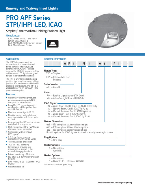
PRO APF Series STPI/IHPI-LED, ICAO Stopbar/ Intermediate Holding Position Light Compliances:ICAO Annex 14 Vol. 1 and Part 4NATO: STANAG 3316FAA: AC 150/5345-46: Current EditionFAA: EB67 Current EditionApplicationsThe STP fixtures are used for runway incursion protection and traffic control on taxiways just before active runways. They are required for SMGCS operations. This unidirectional LED light is designed for use in all weather conditions.The IHP is an intermediate holding position light used to mark a holding position that has been established to protect a priority route. The IHP is a unidirectional yellow light with 12W power consumption.FeaturesWavetrac™ technology reduces power consumption up to60%compared to incandescentLong life LED technology with rated projected life greater than50,000h at 6.6ADust and water tight to IP 68Modular design makes fixtures easy to maintain with fewer partsto stockEngineering Brief 67 current edition compliant dimming curveHigh frequency 400Hz PWM helps eliminate flicker perceptionCompatible with all knownCCR types*3.5 Crest factor ensurescompatibility with Series CCRs10kV/5kA surge protection-40C to +85C operatingtemperature ensures safemovement of aircraft in themost challenging locationsFailure monitoring of fixturesIEC Style 3, 6-13mm low protusion housingLow Profile, < .25˝ (6.35mm) –FAA Style 3Optional arctic kitFixture T ype:STPI = StopbarIHPI = Intermediate HoldPositionSeries Version:AP1= ProAPF1Color:R/N = Red/No Light Source (STPI Only)Y/N = Y ellow/No light Source(IHPI Only)ICAO Figure:12 = Wide Beam, Cat III, ICAO fig A2-12 (IHPI Only)13 = Narrow Beam, Cat III, ICAO fig A2-1314 = Curved Sections, Cat III, ICAO fig A2-1415 = Wide Beam , Cat II, CAO fig A2-1516 = Curved Sections, Cat II, ICAO fig A2-16Fixture Dimension:08S = IEC compliant 203mm/8inch straight08R = IEC compliant 203mm/8inch right-toe08L = IEC compliant 203mm/8inch left-toeR and L options for ICAO figures 2-14 and 2-16 only (no straight option) Plug Options:P1 = One plugHeater Options:0 = No options1=ArctickitGasket Options:0 = No options1 = Gasket 1 (C.H. Canister #22537)Contact factory for other gasket sizingOrdering Information* O perates with Thyristor (Series) CCRs across 6 or 8 steps for ICAO/airportlightingOutline Drawings2-12IHPI Y 10.110W/15W 0.992-13IHPI Y 6.910W/15W 0.992-13STPI R 7.110W/15W 0.992-14IHPI Y 9.410W/15W 0.992-14STPI R 9.810W/15W 0.992-15IHPI Y 7.910W/15W 0.992-15STPI R 7.510W/15W 0.992-16IHPI Y 7.910W/15W 0.992-16STPIR8.110W/15W0.99* Use 30W/45W with the Arctic Kit Option.Figure 2-14Figure 2-13Figure 2-12Figure 2-15Dimensions:Inches (mm)Instruction Manual: 1136Shipping Weight: 5.4 lbs. 2.44kg.Shipping Volume:.17 cu. ft. .004 m3*Order base separatelyAccessories & Renewal PartsItem DescriptionCatalog Number Item DescriptionCatalog Number LED Module Replacements –Fig A2-12/Fig A2-15 Yellow Module21664-F212-F215-Y LED Module Replacements – Fig A2-15 Red Module 21664-F215-R LED Module Replacements – Fig A2-13 Yellow Module 21664-F213-Y LED Module Replacements – Fig A2-13 Red Module 21664-F213-R LED Module Replacements –Fig A2-14/Fig A2-16 Yellow Module 21664-F214-F216-Y LED Module Replacements – Fig A2-14/Fig A2-16 Red Module21664-F214-F216-R Lens Replacements – Fig A2-12, A2-13, A2-15 21642-C Lens Replacements – Fig A2-14, A2-1621643Lens Replacements, Arctic Kit Option Fig A2-12, A2-13, A2-1521644-1Lens Replacements, Arctic Kit Option Fig A2-14, A2-16 21644-2Power Supply Replacement Kit21645-1Power Supply Replacement Kit Arctic Kit Support 21645-2Feed through Assembly 21122O-Ring, Optical Housing10035-0062External Seal Gasket, 165mm bore 21612External Seal Gasket, 167.9mm bore 21613External Seal Gasket, 168.7mm bore 216142 Piece Lock Washer Kit, Qty 221647-2Home Office: United States – +1 860-683-4300International Offices: Canada • China • Dubai • Mexico • Brazil。
ICAO 附件14机场 第六版

国际标准和建议措施国际民用航空公约附件14 (Annex 14)机场第I卷机场设计和运行本版编入了2013年2月28日以前理事会通过的所有修订,并自2013年11月14日起取代附件14第I 卷所有以前的版本。
关于标准和建议措施的适用范围,参见第 1章 1.2和前言。
2013年7月第六版国际民用航空组织国际标准和建议措施国际民用航空公约附件14 (Annex 14)机场第I卷机场设计和运行本版编入了2013年2月28日以前理事会通过的所有修订,并自2013年11月14日起取代附件14第I 卷所有以前的版本。
关于标准和建议措施的适用范围,参见第 1章 1.2和前言。
2013年7月第六版国际民用航空组织国际民用航空组织分别以中文、阿拉伯文、英文、法文、俄文和西班牙文版本出版999 University Street, Montréal, Quebec, Canada H3C 5H7订购信息和经销商与书商的详尽名单,请查阅国际民航组织网站www.icao.int。
第一版—1990年第五版—2009年第六版—2013年附件14—《机场》第I卷《机场设计和运行》订购编号:AN 14-1ISBN 978-92-9249-291-5© ICAO 2013保留所有权利。
未经国际民用航空组织事先书面许可,不得将本出版物的任何部分复制、存储于检索系统或以任何形式或手段进行发送。
修订《国际民航组织出版物目录》的补篇中公布了各项修订;在国际民航组织网站www.icao.int上有本目录及其补篇。
以下篇幅供记录修订之用。
修订和更正记录(iii)目录页码缩写和符号 (x)出版物 (xi)前言 (xiii)第1章总则…………………………………………………………………………………………………1-11.1 定义…………………………………………………………………………………………………1-11.2 适用范围……………………………………………………………………………………………1-91.3 共同参照系…………………………………………………………………………………………1-91.4 机场合格审定………………………………………………………………………………………1-101.5 机场设计……………………………………………………………………………………………1-101.6 基准代号……………………………………………………………………………………………1-10第2章机场数据……………………………………………………………………………………………2-12.1 航空数据……………………………………………………………………………………………2-12.2 机场基准点…………………………………………………………………………………………2-22.3 机场和跑道标高……………………………………………………………………………………2-22.4 机场基准温度………………………………………………………………………………………2-22.5 机场的尺寸和有关资料……………………………………………………………………………2-32.6 道面的强度…………………………………………………………………………………………2-42.7 飞行前高度表校正位置……………………………………………………………………………2-62.8 公布的距离…………………………………………………………………………………………2-72.9 活动区及有关设施的情况…………………………………………………………………………2-72.10 移去损坏的航空器…………………………………………………………………………………2-102.11 救援与消防…………………………………………………………………………………………2-102.12 目视进近坡度指示系统……………………………………………………………………………2-102.13 航空情报服务部门和机场当局之间的协调………………………………………………………2-11第3章物理特性……………………………………………………………………………………………3-13.1 跑道…………………………………………………………………………………………………3-13.2 跑道道肩……………………………………………………………………………………………3-73.3 跑道调头坪…………………………………………………………………………………………3-83.4 升降带………………………………………………………………………………………………3-103.5 跑道端安全区………………………………………………………………………………………3-133.6 净空道………………………………………………………………………………………………3-143.7 停止道………………………………………………………………………………………………3-153.8 无线电高度表操作场地……………………………………………………………………………3-163.9 滑行道………………………………………………………………………………………………3-173.10 滑行道道肩…………………………………………………………………………………………3-233.11 滑行带………………………………………………………………………………………………3-24附件14 —第I卷(v)14/11/13附件14 —机场第I卷14/11/13(vi) 页码3.12 等待坪、跑道等待位置、中间等待位置和道路等待位置………………………………………3-253.13 机坪…………………………………………………………………………………………………3-273.14 被隔离的航空器的停放位置………………………………………………………………………3-283.15 除冰/防冰设施……………………………………………………………………………………3-28第4章障碍物的限制和清除………………………………………………………………………………4-14.1 障碍物限制面………………………………………………………………………………………4-14.2 障碍物限制要求……………………………………………………………………………………4-64.3 障碍物限制面以外的物体…………………………………………………………………………4-124.4 其他物体……………………………………………………………………………………………4-12第5章目视助航设施………………………………………………………………………………………5-15.1 指示标和信号设施…………………………………………………………………………………5-15.1.1 风向标……………………………………………………………………………………5-15.1.2 着陆方向标………………………………………………………………………………5-15.1.3 信号灯……………………………………………………………………………………5-25.1.4 信号板和信号场地………………………………………………………………………5-35.2 标志…………………………………………………………………………………………………5-35.2.1 概述………………………………………………………………………………………5-35.2.2 跑道号码标志……………………………………………………………………………5-45.2.3 跑道中线标志……………………………………………………………………………5-65.2.4 跑道入口标志……………………………………………………………………………5-65.2.5 瞄准点标志………………………………………………………………………………5-95.2.6 接地带标志………………………………………………………………………………5-105.2.7 跑道边线标志……………………………………………………………………………5-115.2.8 滑行道中线标志…………………………………………………………………………5-135.2.9 跑道调头坪标志…………………………………………………………………………5-165.2.10 跑道等待位置标志………………………………………………………………………5-175.2.11 中间等待位置标志………………………………………………………………………5-185.2.12 VOR机场校准点标志……………………………………………………………………5-195.2.13 航空器停机位标志………………………………………………………………………5-205.2.14 机坪安全线………………………………………………………………………………5-215.2.15 道路等待位置标志………………………………………………………………………5-215.2.16 强制性指令标志…………………………………………………………………………5-225.2.17 信息标志…………………………………………………………………………………5-235.3 灯光…………………………………………………………………………………………………5-245.3.1 概述………………………………………………………………………………………5-245.3.2 应急灯光…………………………………………………………………………………5-295.3.3 航空灯标…………………………………………………………………………………5-295.3.4 进近灯光系统……………………………………………………………………………5-315.3.5 目视进近坡度指示系统…………………………………………………………………5-385.3.6 盘旋引导灯………………………………………………………………………………5-505.3.7 跑道引入灯光系统………………………………………………………………………5-505.3.8 跑道入口识别灯…………………………………………………………………………5-515.3.9 跑道边灯…………………………………………………………………………………5-525.3.10 跑道入口灯和翼排灯……………………………………………………………………5-535.3.11 跑道末端灯………………………………………………………………………………5-54目录附件14 —机场页码5.3.12 跑道中线灯………………………………………………………………………………5-565.3.13 跑道接地带灯……………………………………………………………………………5-585.3.14 简易接地带灯……………………………………………………………………………5-585.3.15 快速出口滑行道指示灯…………………………………………………………………5-605.3.16 停止道灯…………………………………………………………………………………5-615.3.17 滑行道中线灯……………………………………………………………………………5-615.3.18 滑行道边灯………………………………………………………………………………5-665.3.19 跑道调头坪灯……………………………………………………………………………5-675.3.20 停止排灯…………………………………………………………………………………5-685.3.21 中间等待位置灯…………………………………………………………………………5-705.3.22 除冰/防冰设施出口灯……………………………………………………………………5-705.3.23 跑道警戒灯………………………………………………………………………………5-715.3.24 机坪泛光照明……………………………………………………………………………5-735.3.25 目视停靠引导系统………………………………………………………………………5-745.3.26 先进的目视停靠引导系统………………………………………………………………5-765.3.27 航空器停机位操作引导灯………………………………………………………………5-785.3.28 道路等待位置灯…………………………………………………………………………5-785.3.29 禁止进入排灯……………………………………………………………………………5-795.4 标记牌………………………………………………………………………………………………5-805.4.1 概述………………………………………………………………………………………5-805.4.2 强制性指令标记牌………………………………………………………………………5-845.4.3 信息标记牌………………………………………………………………………………5-875.4.4 VOR机场校准点标记牌…………………………………………………………………5-895.4.5 机场识别标记牌…………………………………………………………………………5-905.4.6 航空器停机位识别标记牌………………………………………………………………5-915.4.7 道路等待位置标记牌……………………………………………………………………5-915.5 标志物………………………………………………………………………………………………5-925.5.1 概述………………………………………………………………………………………5-925.5.2 无铺砌面跑道的边线标志物……………………………………………………………5-925.5.3 停止道边线标志物………………………………………………………………………5-935.5.4 表面积雪的跑道边线标志物……………………………………………………………5-935.5.5 滑行道边线标志物………………………………………………………………………5-935.5.6 滑行道中线标志物………………………………………………………………………5-945.5.7 无铺砌面的滑行道边线标志物…………………………………………………………5-945.5.8 边界标志物………………………………………………………………………………5-95第6章标示障碍物的目视助航设施………………………………………………………………………6-16.1 需加标志和/或照明的物体………………………………………………………………………6-16.2 物体的标志和/或照明……………………………………………………………………………6-3第7章标示限制使用区的目视助航设施…………………………………………………………………7-17.1 关闭的跑道和滑行道或其部分……………………………………………………………………7-17.2 非承重表面…………………………………………………………………………………………7-17.3 跑道入口前地区……………………………………………………………………………………7-37.4 非适用区……………………………………………………………………………………………7-3(vii)14/11/13附件14 —机场第I卷14/11/13(viii) 页码第8章电气系统……………………………………………………………………………………………8-18.1 导航设施供电系统…………………………………………………………………………………8-18.2 系统设计……………………………………………………………………………………………8-28.3 监控…………………………………………………………………………………………………8-4第9章机场运行服务、设备和装置………………………………………………………………………9-19.1 机场应急计划………………………………………………………………………………………9-19.2 救援与消防…………………………………………………………………………………………9-39.3 移去损坏的航空器…………………………………………………………………………………9-109.4 减轻野生动物袭击的危害…………………………………………………………………………9-109.5 机坪管理服务………………………………………………………………………………………9-119.6 航空器地面服务……………………………………………………………………………………9-129.7 机场车辆的运行……………………………………………………………………………………9-129.8 地面活动引导和控制系统…………………………………………………………………………9-139.9 运行地区设备和装置的定位………………………………………………………………………9-149.10 栅栏…………………………………………………………………………………………………9-159.11 保安照明……………………………………………………………………………………………9-16第10章机场维护……………………………………………………………………………………………10-110.1 概述…………………………………………………………………………………………………10-110.2 道面…………………………………………………………………………………………………10-110.3 污染物的清除………………………………………………………………………………………10-210.4 跑道道面加覆盖层…………………………………………………………………………………10-310.5 目视助航设备………………………………………………………………………………………10-3附录1 航空地面灯、标志、标记牌和面板的颜色………………………………………………………APP 1-11. 概述…………………………………………………………………………………………………APP 1-12. 航空地面灯的颜色…………………………………………………………………………………APP 1-13. 标志、标记牌和面板的颜色………………………………………………………………………APP 1-3附录2 航空地面灯的特性…………………………………………………………………………………APP 2-1附录3 强制性指令标志和信息标志………………………………………………………………………APP 3-1附录4 有关滑行引导标记牌的设计要求…………………………………………………………………APP 4-1附录5 航空数据质量要求…………………………………………………………………………………APP 5-1附录6 障碍物灯的位置……………………………………………………………………………………APP 6-1附篇A 附件14第I卷的补充指导材料……………………………………………………………………A TT A-11. 跑道的条数、定位和定向…………………………………………………………………………A TT A-12. 净空道和停止道……………………………………………………………………………………A TT A-23. 公布距离的计算……………………………………………………………………………………A TT A-34. 跑道上的坡度………………………………………………………………………………………A TT A-4目录附件14 —机场页码5. 跑道表面的平坦度…………………………………………………………………………………A TT A-66. 评估被冰、半融雪、雪和霜覆盖的铺砌道面的表面的表面摩阻特性……………………………A TT A-77. 为修建和维护目的确定表面摩擦特性A TT A-98. 活动区和相邻地区的排水性能……………………………………………………………………A TT A-109. 升降带………………………………………………………………………………………………A TT A-1310. 跑道端安全区………………………………………………………………………………………A TT A-1411. 跑道入口的位置……………………………………………………………………………………A TT A-1512. 进近灯光系统………………………………………………………………………………………A TT A-1613. 设置目视进近坡度指示系统的优先顺序…………………………………………………………A TT A-2314. 非适用区的灯光……………………………………………………………………………………A TT A-2415. 快速出口滑行道指示灯……………………………………………………………………………A TT A-2416. 进近灯和跑道灯的光强控制………………………………………………………………………A TT A-2417. 信号区………………………………………………………………………………………………A TT A-2518. 救援与消防服务……………………………………………………………………………………A TT A-2519. 车辆操纵人员………………………………………………………………………………………A TT A-2720.通报道面强度的ACN-PCN方法...........................................................................A TT A-28 附篇B 障碍物限制面...................................................................................................A TT B-1 附件14第I卷中重要主题提要索引 (1)(ix)14/11/13附件14 —机场第I卷缩写和符号(用于附件14,卷I)缩写ACN Aircraft classification number 飞机等级序号APAPI Abbreviated precision approach path indicator 简化精密进近航道指示器aprx Approximately 大致ASDA Accelerate-stop distance available 可用加速—停止距离ATS Air traffic services 空中交通服务AT-V ASIS Abbreviated T visual approach slope indicator system 简化T式目视进近坡度指示系统C Degree Celsius 摄氏度CBR California bearing ratio 加州承载比cd Candela 坎德拉(烛光)CIE Commission Internationale de I‘Eclairage国际照明委员会cm Centimetre 厘米DME Distance measuring equipment 测距仪ft Foot 英尺ILS Instrument landing system 仪表着陆系统IMC Instrument meteorological conditions 仪表气象条件K Degree Kelvin 绝对温度(开尔文)度数kg Kilogram 千克km Kilometre 千米km/h Kilometre per hour 千米/时kt Knot 海里/时(节)L Litre 升LDA Landing distance available 可用着陆距离m Metre 米max Maximum 最大MLS Microwave landing system 微波着陆系统mm Millimetre 毫米mnm Minimum 最小MN Meganewton 兆牛(顿)Mpa Megapascal 兆帕(斯卡)NM Nautical mile 海里NU Not usable 不能使用OCA/H Obstacle clearance altitude/height 超障高度/超障高OFZ Obstacle free zone 无障碍区OLS Obstacle limitation surface 障碍物限制面PAPI Precision approach path indicator 精密进近航道指示器PCN Pavement classification number 道面等级序号RESA Runway end safety area 跑道端安全区RVR Runway visual range 跑道视程TODA Take-off distance available 可用起飞距离TORA Take-off run available 可用起飞滑跑距离T-VASIS T visual approach slope indicator system T式目视进近坡度指示系统VMC Visual meteorological conditions 目视气象条件VOR Very high frequency omnidirectional radio range 甚高频全向信标符号°Degree 度=Equal 等于′Minute of arc 弧度分μFriction coefficient 摩阻系数>Greater than 大于<Less than 小于% Percentage 百分比±Plus or minus 加或减14/11/13(x)出版物附件14 —机场出版物(与本附件的规范有关的)《改进型地面活动引导及控制系统(A-SMGCS)手册》(Doc 9830号文件)《机场设计手册》(Doc 9157号文件)第1部分—跑道第2部分—滑行道,机坪和等待坪第3部分—道面第4部分—目视助航设备第5部分—电气系统第6部分—易折性《航空情报服务手册》(Doc 8126号文件)《航空器机型代码》(Doc 8643号文件)《机场规划手册》(Doc 9184号文件)第1部分—总体规划第2部分—土地利用和环境控制第3部分—咨询/建设服务指南《机场服务手册》(Doc 9137号文件)第1部分—救援与消防第2部分—道面表面条件第3部分—野生动物的控制与减少第5部分—移去损坏的飞机第6部分—障碍物的控制第7部分—机场应急计划第8部分—机场运行服务第9部分—机场维护措施《空中交通服务规划手册》(Doc 9426号文件)《适航手册》(Doc 9760号文件)第I卷—组织和程序第II卷—设计合格审定和持续适航性《航空器噪声管理平衡做法指南》(Doc 9829号文件)(xi) 14/11/13附件14 —机场第I卷《直升机场手册》(Doc 9261号文件)《人的因素训练手册》(Doc 9683号文件)《航空器地面除冰/防冰作业手册》(Doc 9640号文件)《场面活动引导及控制系统(SMGCS)手册》(Doc 9476号文件)《机场合格审定手册》(Doc 9774号文件)《激光发射器和飞行安全手册》(Doc 9815号文件)《平行或近似平行跑道同时仪表运行(SOIR)手册》(Doc 9643号文件)《国际民航组织鸟害情报系统(IBIS)手册》(Doc 9332号文件)《空中航行服务程序—航空器运行》(PANS-OPS)(Doc 8168号文件)第I卷—飞行程序第II卷—目视和仪表飞行程序设计《空中航行服务程序—空中交通管理》(PANS-ATM)(Doc 4444号文件)《安全管理手册(SMM)》(Doc 9859号文件《短距起降机场手册》(Doc 9150号文件)《世界大地测量系统— 1984(WGS-84)手册》(Doc 9674号文件)____________________14/11/13(xii)前言历史背景机场标准和建议措施是理事会于1951年5月29日依据《国际民用航空公约》(1944年于芝加哥签署)第三十七条的规定首次通过的,并定为公约的附件14。
ICAO大全
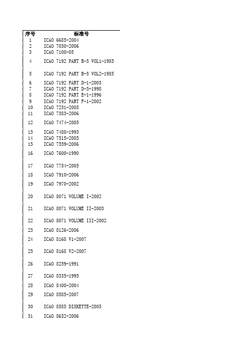
序号 标准号1 ICAO 6685-20042 ICAO 7030-20063 ICAO 7100-054 ICAO 7192 PART B-5 VOL1-19855 ICAO 7192 PART B-5 VOL2-19856 ICAO 7192 PART D-1-20037 ICAO 7192 PART D-3-19988 ICAO 7192 PART E-1-19969 ICAO 7192 PART F-1-200210 ICAO 7231-200511 ICAO 7383-200612 ICAO 7474-200513 ICAO 7488-199314 ICAO 7515-200515 ICAO 7559-200616 ICAO 7600-199017 ICAO 7754-200518 ICAO 7910-200619 ICAO 7970-200220 ICAO 8071 VOLUME I-200221 ICAO 8071 VOLUME II-200322 ICAO 8071 VOLUME III-200223 ICAO 8126-200624 ICAO 8168 V1-200725 ICAO 8168 V2-200726 ICAO 8259-199127 ICAO 8335-199528 ICAO 8400-200429 ICAO 8585-200730 ICAO 8585 DISKETTE-200531 ICAO 8632-200632 ICAO 8643-200733 ICAO 8697-200634 ICAO 8733-200535 ICAO 8896 -200636 ICAO 8900 -200037 ICAO 8973-200038 ICAO 8984-198539 ICAO 9082-200440 ICAO 9137 P1-199541 ICAO 9137 P2-200242 ICAO 9137 P3-199143 ICAO 9137 P5-199644 ICAO 9137 P6-8345 ICAO 9137 P7-199146 ICAO 9137 P8-8347 ICAO 9137 P9-8448 ICAO 9150-200249 ICAO 9157 PART 1-200650 ICAO 9157 PART 2-200551 ICAO 9157 PART 3-198952 ICAO 9157 PART 4-200453 ICAO 9157 PART 5 -198354 ICAO 9157 PART 6-200655 ICAO 9161-199756 ICAO 9184 P1-200457 ICAO 9184 P2-200358 ICAO 9184 P3-198359 ICAO 9684-200660 ICAO 9688-200461 ICAO 9691-200162 ICAO 9694-199963 ICAO 9705-200264 ICAO 9713 -200165 ICAO 9713 CD-200266 ICAO 9718-200767 ICAO 9721-199868 ICAO 9731 VOLUME I-200669 ICAO 9261-199570 ICAO 9274-198371 ICAO 9284-200672 ICAO 9284 SUPPLEMENT-200773 ICAO 9303 P1 V1-200674 ICAO 9303 P1 V2-200675 ICAO 9303 P2-200576 ICAO 9303 P3-200277 ICAO 9328-200578 ICAO 9332-198979 ICAO 9365-200280 ICAO 9368-200281 ICAO 9371-198682 ICAO 9375 P1-199383 ICAO 9375 P2-199384 ICAO 9375 P3-199385 ICAO 9375 P4-199386 ICAO 9376-199787 ICAO 9377-200388 ICAO 9379-200489 ICAO 9389-199690 ICAO 9401-199891 ICAO 9422-198492 ICAO 9426-200293 ICAO 9432-200694 ICAO 9481-200695 ICAO 9501-200496 ICAO 9554-199097 ICAO 9562-200698 ICAO 9574-200299 ICAO 9603-1991100 ICAO 9613-2003101 ICAO 9625-2003102 ICAO 9626-2005103 ICAO 9640-2000104 ICAO 9643-2004105 ICAO 9673-2006106 ICAO 9674-2002107 ICAO 9683-2005108 ICAO 9683 SPANISH-2004 109 ICAO 9731 VOLUME II-2006 110 ICAO 9731 VOLUME III-2006 111 ICAO 9734 PART A-2006112 ICAO 9734 PART B-2006113 ICAO 9735 -2006114 ICAO 9739-2002115 ICAO 9750-2002116 ICAO 9760-2005117 ICAO 9773-2001118 ICAO 9774-2001119 ICAO 9776-2002120 ICAO 9783-2001121 ICAO 9790-2004122 ICAO 9800-2002123 ICAO 9803-2002124 ICAO 9804-2002125 ICAO 9808 -2002126 ICAO 9811-2003127 ICAO 9814-2003128 ICAO 9815-2003129 ICAO 9821-2002130 ICAO 9821-171131 ICAO 9824-2003132 ICAO 9829-2004133 ICAO 9830-2004134 ICAO 9832-2004135 ICAO 9835-2004136 ICAO 9841-2006137 ICAO 9855-2005138 ICAO 9859-2006139 ICAO 9863-2006140 ICAO ACDB V1-2006141 ICAO ANNEX 1-2006142 ICAO ANNEX 10 V1-2006143 ICAO ANNEX 10 V2-2005144 ICAO ANNEX 10 V3-2006145 ICAO ANNEX 10 V4-2006 146 ICAO ANNEX 10 V5-2006147 ICAO ANNEX 11-2006148 ICAO ANNEX 12-2005149 ICAO ANNEX 13 -2006 150 ICAO ANNEX 14 V1 -2006 151 ICAO ANNEX 14 V2-2004 152 ICAO ANNEX 15-2005153 ICAO ANNEX 16 V1-2005 154 ICAO ANNEX 16 V2-2005 155 ICAO ANNEX 17-2002156 ICAO ANNEX 18-2005157 ICAO ANNEX 2-2005158 ICAO ANNEX 3-2006159 ICAO ANNEX 4-2005160 ICAO ANNEX 5-2004161 ICAO ANNEX 6 PT1-2006 162 ICAO ANNEX 6 PT2-2005 163 ICAO ANNEX 6 PT3-2006 164 ICAO ANNEX 7-2004165 ICAO ANNEX 8-2005166 ICAO ANNEX 9-2005167 ICAO CIRCULAR 284-2002 168 ICAO CIRCULAR 285-2001 169 ICAO CIRCULAR 286-2003 170 ICAO CIRCULAR 287-2002 171 ICAO CIRCULAR 288-2002 172 ICAO CIRCULAR 289-2002 173 ICAO CIRCULAR 290-2002 174 ICAO CIRCULAR 291-2004 175 ICAO CIRCULAR 302-2004 176 ICAO CIRCULAR 303-2004 177 ICAO CIRCULAR 304-2004 178 ICAO CIRCULAR 312-2007179 ICAO INDEX-2007180 ICAO 7474 V1-2004181 ICAO 7474 V2-2004182 ICAO 9303 P1-2003183 ICAO 9685-1997184 ICAO 9700-1998185 ICAO 9732-1999186 ICAO 9787-2001187 ICAO ANNEX 14-1989188 ICAO CIRCULAR 207-1988 189 ICAO CIRCULAR 279-2000AIRCRAFT TYPE DESIGNATORSAERONAUTICAL CHART MANUALAIR NAVIGATION PLAN - CARIBBEAN AND SOUTH AMERICAN REGIONS VOLUME I BASIC ANP & VOLUME II FASIDMANUAL OF AERONAUTICAL METEOROLOGICAL PRACTICEREPERTORY - GUIDE TO THE CONVENTION ON INTERNATIONAL CIVIL AVIATIONSECURITY MANUAL FOR SAFEGUARDING CIVIL AVIATION AGAINST ACTS OF UNLAWFUL INTERFERENCE RESTRICTEDMANUAL OF CIVIL AVIATION MEDICINEICAOS POLICIES ON CHARGES FOR AIRPORTS AND AIR NAVIGATION SERVICESAIRPORT SERVICES MANUAL - PART 1 RESCUE AND FIRE FIGHTINGAIRPORT SERVICES MANUAL - PART 2 PAVEMENT SURFACE CONDITIONSAIRPORT SERVICES MANUAL - PART 3 BIRD CONTROL AND REDUCTIONAIRPORT SERVICES MANUAL - PART 5 REMOVAL OF DISABLED AIRCRAFTAIRPORT SERVICES MANUAL - PART 6 CONTROL OF OBSTACLESAIRPORT SERVICES MANUAL - PART 7 AIRPORT EMERGENCY PLANNINGAIRPORT SERVICE MANUAL - PART 8 AIRPORT OPERATIONAL SERVICESAIRPORT SERVICES MANUAL - PART 9 AIRPORT MAINTENANCE PRACTICESSTOLPORT MANUALAERODROME DESIGN MANUAL PART 1 RUNWAYSAERODROME DESIGN MANUAL PART 2 TAXIWAYS APRONS AND HOLDING BAYSAERODROME DESIGN MANUAL PART 3 PAVEMENTSAERODROME DESIGN MANUAL PART 4 VISUAL AIDSAERODROME DESIGN MANUAL PART 5 ELECTRICAL SYSTEMSAERODROME DESIGN MANUAL PART 6 - FRANGIBILITYMANUAL ON AIR NAVIGATION SERVICES ECONOMICSAIRPORT PLANNING MANUAL - PART 1 MASTER PLANNINGAIRPORT PLANNING MANUAL - PART 2 LAND USE AND ENVIRONMENTAL CONTROLAIRPORT PLANNING MANUAL PART 3 GUIDELINES FOR CONSULTANT/CONSTRUCTION SERVICES MANUAL ON THE SECONDARY SURVEILLANCE RADAR (SSR) SYSTEMSMANUAL ON MODE S SPECIFIC SERVICESMANUAL ON VOLCANIC ASH RADIOACTIVE MATERIAL AND TOXIC CHEMICAL CLOUDSMANUAL OF AIR TRAFFIC SERVICES DATA LINK APPLICATIONSMANUAL OF TECHNICAL PROVISIONS FOR AERONAUTICAL TELECOMMUNICATION NETWORK (ATN) INTERNATIONAL CIVIL AVIATION VOCABULARY - VOLUMES 1 AND 2INTERNATIONAL CIVIL AVIATION VOCABULARY - VOLUMES 1 AND 2HANDBOOK ON RADIO FREQUENCY SPECTRUM REQUIREMENTS FOR CIVIL AVIATION - INCLUDING STATEMENT OF APPROVED ICAO POLICIESPROTOCOL ON THE AUTHENTIC SIX-LANGUAGE TEXT OF THE CONVENTION ON INTERNATIONAL CIVIL AVIATIONAMSAR MANUAL INTERNATIONAL AERONAUTICAL AND MARITIME SEARCH AND RESCUE MANUAL -VOLUME I - ORGANIZATION AND MANAGEMENTHELIPORT MANUALMANUAL ON THE USE OF THE COLLISION RISK MODEL (CRM) FOR ILS OPERATIONS TECHNICAL INSTRUCTIONS FOR THE SAFE TRANSPORT OF DANGEROUS GOODS BY AIR TECHNICAL INSTRUCTIONS FOR THE SAFE TRANSPORT OF DANGEROUS GOODS BY AIR。
LIRA LED 航空灯说明书
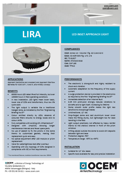
LIRALED INSET APPROACH LIGHTPERFORMANCES• The electronic is strong-built and highly resistant to shock and vibration• Automatic adaptation to the frequency of the supply current• A surge protection device is provided in the electronics as required by the FAA “Engineering Briefing No.67” • Immediate detection of an internal fault• 6.35 mm protrusion strongly reduces vibrations to aircrafts and to light itself, increasing its lifetime• Dome smooth outer profile makes the light less sensitive to snowplough blades • Unidirectional, 12" dia.•Drop-forged dome and cast aluminium lower cover make the fitting sturdy, but lightweight too for ease handling in the field•Light output practically not affected by heavy rainfall thanks to the shallow channel in front of the prism windows• O-Ring placed outside the dome to avoid dirt deposits between light and base • Protection degree: IP67• Temperature range: -55°C to +55°CINSTALLATION• Suitable for 12” d ia. bases• Specific tools available for easy and precise installationCOMPLIANCESICAO: Annex 14 - Volume I Fig. A2-1 and A2-2 EASA: CS-ADR-DSN Fig. U-5, U-6 IEC: TS 61827NATO: STANAG 3316 CAA: CAP 168 IAAE: TP312 *************APPLICATIONSApproach (centreline and crossbars) and Approach Side Row Barrettes for ICAO CAT I, II and III, and military runwaysBENEFITS• 60000 hours LED rated life at full intensity, but over 100000 hours in field operating conditions•In new installation, LED lights mean lower loads, lower size of CCRs and transformers, thus low life cycle costs•The light output is variable like a traditional halogen lamp, as indicated by the FAA “Engineering Briefing No.67”•Colour emitted directly by LEDs: absence of coloured filters ensures no energy losses and no colour shifts• Fully compatible with existing AFL infrastracture* • Designed with simplicity allowing longer maintenance intervals and fewer spare parts•No use of sealant to fix the prisms in the dome thanks to customized gaskets, making their replacement quick and easy• No optical adjustment after LED module or prism replacement• Valve for watertightness test after overhaul•Operating with any topology of CCRs designed in compliance with IEC or FAA requirements* For monitored fixtures, isolation transformer max size: 200VALight Fixture 12” dia.Shallow Base 12” dia.L-868 Deep Base 12” dia.6.35ø252.3ø30419150ø320ø340160106196106.35ø252.3ø304LIRA- W - L - M - 0Basic P/N :Colour: W = White R = RedToe-in*: R = Left L = Right S = StraightS1 = Special Version(installation 475 m beyond the threshold)Monitoring:0 = Without Monitoring M = With MonitoringArctic Kit:0 = Without Arctic Kit A = With Arctic Kit* The beam aiming is not field adjustable*************30°60°TYPICAL Ø286ACCESSORI315.1230 Base L-868 type, class IA, size B, 24” deep * 315.1420 Flange ring with pavement dam for L-868 base, size B, with O-Ring and bolts152.8110 Shallow base, 12" dia., one cable lead, with gasket and hardware712.1034 Setting material for shallow base, 10 lt 712.1035 Quartz for shallow base, 25 kg332.4301 Positioning jig for 8"-12" dia. shallow base, without optical device332.4351 Optical device for positioning jig to allow a very precise light unit orientation332.4330 Watertight/shockproof plastic case complete with positioning jig for base and optical device 332.4140 Lifting tool (2 pieces to work properly) 332.4230 Lifting tool with double hook* Sectional bases may be required depending upon the paving techniqueFor any information about isolating transformers and connectors, please see the specific catalogue pagesShipping Weights and VolumesLight Unit Shallow BaseWeight (kg) 8.5 7.3 Volume (m 3)0.0220.022We reserve the right to change the design or specification data without notice*************UC-PU-0314_EN-RevCMAIN COMPONENTS OF THE LIGHT UNIT1 Dome with prisms and gaskets2 O-Ring for dome (external)3 O-Ring for dome (internal)4 O-Ring for lower cover5 Arctic Kit heater6 Lens array7 LED module8 Lower cover with electronic, plug and valve 9 Valve for watertightness test 10 FAA L-823 plug11 Arctic Kit thermostat 12 Prism Gasket 13 Prism14 Prism holder gasket 15Mounting plateRefer to the relevant technical manual for the complete list of the available spare parts。
专业考试辅导课讲义通航建筑物

目
CONTENCT
录
• 通航建筑物概述 • 通航建筑物的设计与建设 • 通航建筑物的运营与管理 • 通航建筑物的法规与标准 • 通航建筑物的未来发展与挑战
01
通航建筑物概述
通航建筑物的定义与特点
定义
通航建筑物是指为船舶提供通行条件的建筑物,包括船闸、升船 机等。
特点
综合效益评价
综合考虑通航建筑物的经济效益和社会效益,为决策 提供依据。
04
通航建筑物的法规与标准
国际通航建筑物法规与标准
要点一
国际民航组织(ICAO)规定
国际通航建筑物必须符合国际民航组织制定的相关标准和 建议措施,包括机场、导航设施、空中交通管理等方面的 标准和建议措施。
要点二
国际通航建筑物安全评估标准 (ICAO Annex 14)
通航建筑物具有大流量、高水头、高流速等特点,需要解决船舶 的通航、过闸等问题。
通航建筑物的历史与发展
历史
通航建筑物最早可以追溯到古代中国 的水利工程,如都江堰、灵渠等,现 代通航建筑物则主要集中在河流、运 河等水域。
发展
随着科技的不断进步,通航建筑物的 设计和建设水平不断提高,出现了越 来越多的新型通航建筑物,如大型船 闸、升船机等。
05
通航建筑物的未来发展与挑战
通航建筑物的技术创新与应用
无人机与机器人技术的应用
无人机和机器人在通航建筑物中的应用越来越广泛 ,如监测、检测、施工等,提高了工作效率和安全 性。
智能化与自动化技术
随着智能化和自动化技术的不断发展,通航建筑物 将实现更高效、精准的操控和管理,提高运营效率 。
新型材料的应用
新型材料如碳纤维、玻璃纤维等在通航建筑物中的 应用,能够减轻结构重量、提高结构强度和耐久性 。
莱特希德-马丁 360° FOD 检测系统 使用说明书

HomeFODiFerret™PartnersCLICK HERE TO STARTA constant threat that necessitates round-the-clock protectionOver half of the airport emergencies around the world are linked to FOD. Such incidents can bring a hefty cost to the aviation industry. With a rigorousstate-of-the-art FOD detection system that accurately picks up and identifies FOD, this threat can be greatly reduced.Limited number ofmanual inspections a day.Runway closure is anopportunity cost.L onger inspectionintervals increase the riskof the presence of FOD.H uman errors can occur.F O D T H R E AT S O N AV E R AG E C A U S ET H E C H A L L E N G E O F M A N U A L I N S P E C T I O N SFatal Accidents per year Losses per year of Total Aircraft IncidentsSource: E U Aviation Safety Agency;Airbus StatisticsSource: EU Aviation Safety Agency Source: ICAO 15USD13B12% V I S U A L C O N D I T I O N FA C T O R SNight-time Fog SnowRainIntroducing an industry-leading FOD detection system that is tried and testedOwned by Changi Airport Group (CAG) and supported by NCS, iFerret™ is used in major airports worldwide to keep their runways safe. Several unique features of iFerret™ have made it the preferred choice for an FOD detection system.Product FeaturesHow It WorksC L I C K T O L E A R N M O R EMultiple Usage Unparalleled Advantages Proven Performance Strategic LocationsAutomated,fast and accuratedetection, locationmeasurement, classification and recording.Powerful optical zoom Real-time,24/7 monitoring Performs under all conditions(low-light, rain, fog, snow) as long as runway remains operational.Recording and analysisIntelligent vision softwarewith state-of-the-artElectro-Optic (EO) Sensors.iFerret™*******************************************************.For more information, visit www.ncs.co.For more information, visit .Changi Airport Group (Singapore) Pte Ltd (CAG) was formed on 16 June 2009 and the corporatisation of Singapore Changi Airport (IATA: SIN, ICAO: WSSS) followed on 1 July 2009. As the company managing Changi Airport, CAG undertakes key functions focusing on airport operations and management, air hub development, commercial activities and airport emergency services. CAG also managesSeletar Airport (IATA: XSP , ICAO: WSSL) and through its subsidiary Changi Airports International, invests in and manages airports around the world.NCS is a leading technology services firm with presence in Asia Pacific and partners with governments and enterprises to advance communities through technology. Combining the experience and expertise of its 10,000-strong team across 55 specialisations, NCS provides differentiated and end-to-end technology services to clients with its NEXT capabilities in digital, cloud and platforms, as well as core offerings in application, infrastructure, engineering and cybersecurity. NCS also believes in building a strong partner ecosystem with leading technology players, research institutions and start-ups to support open innovation and co-creation.About Us Our T echnology PartnerTrack recordIn compliance with specifications from| Singapore Changi Airport | Dubai International Airport || Hong Kong International Airport | Chicago O’Hare International Airport || Federal Aviation Administration (FAA) AC 150/5220-24 and AC 150/5210-24 | | International Civil Aviation Organization (ICAO) Annex 14 |。
【课件】民用机场基础知识(铺助机场学习用-非一建课件)
航站区与航站楼
站坪机位尺寸确定
确定机坪面积用的飞机数据
航站区与航站楼
确定机位面积用的飞机主要尺寸
航站区与航站楼
净距要求
航站区与航站楼
飞机停放方式
飞机地面服务要求
行李运输
1)定义 旅客在旅行中为了穿着、使用、舒适或者便利 而携带的必要或者适量的物品和其他个人财物 称作行李(BAGGAGE)。 2)类别 (1)托运行李(CHECKED BAGGAGE) (2)自理行李(UNCHECKED BAGGAGE) (3)随身携带行李(CARRY ON/CABIN BAGGAGE)
民用机场的功能分区
现代运输机场飞行区组成
民用机场的功能分区——飞行区
1.升降带 1)跑道 2)跑道道肩 3)停止道 4)升降带土质地区
民用机场的功能分区——飞行区
2.跑道端安全区 3.净空道 4.滑行道 5.机坪
民用机场的功能分区——航站区
1.航站楼 1)联接地面交通的设施 2)办理各种离港手续的设施 3)联接飞行的设施 4)航空公司营运和机场管理部门必要的办公 室、设备等 5)服务设施 有餐厅、商店、银行等。 2.停车场所
机场跑道方位
例:天津机场跑道磁方位角为160-340,则南端识别 号码为34,北端识别号码为16。 两条以上时: 则在每个识别标志数字后面(或下面)必须增加一个字 母 字母为从进近方向看去自左至右的顺序 如两条跑道则为“L”、“R”;如三条跑道则为“L”、 “C” 、“R”…
机场跑道方位
首都机场三条平行跑道
航站区与航站楼
B747-400 指廊式集 结机头垂 直向内停 放的站坪 基本尺寸
飞行器翼灯标准_解释说明以及概述
飞行器翼灯标准解释说明以及概述1. 引言1.1 概述:本文旨在探讨飞行器翼灯标准的解释说明以及概述。
翼灯作为飞行器上的重要设备之一,起着引导、警示和通信的作用。
飞行器翼灯标准的制定对保障飞行安全、促进目视导航与通信能力至关重要。
通过对国际航空组织标准(ICAO)、国家民航局标准(CAA)以及行业协会标准(例如AIAA)进行综合分析,我们将全面了解到不同标准所提出的要求和规定,并深入探讨其实际应用背后的意义和价值。
1.2 文章结构:本文分为五个部分:引言、飞行器翼灯标准解释说明、飞行器翼灯标准概述、飞行器翼灯标准的重要性以及结论。
首先,在引言中,我们将介绍本篇文章对于飞行器翼灯标准的阐述内容以及整体结构安排。
然后,在第二部分,我们将详细解释和说明飞行器翼灯的定义、作用以及分类特点等方面。
在第三部分,我们将对国际航空组织标准(ICAO)、国家民航局标准(CAA)以及行业协会标准进行概述性介绍,探讨不同标准对飞行器翼灯的要求和规定。
在第四部分,我们将重点论述飞行器翼灯标准在安全性考虑和改善目视导航与通信能力方面的重要性,并提供具体例证加以支撑。
最后,在结论中,我们将总结全文所述内容并强调飞行器翼灯标准的意义与作用。
1.3 目的:本文的主要目的是通过解释说明和概述飞行器翼灯标准,使读者对飞行器翼灯的定义、作用、分类特点以及不同标准之间的差异有更加深入和清晰的理解。
同时,本文还旨在强调飞行器翼灯标准在保障安全、提高目视导航与通信能力方面的重要性。
通过阐述其意义与价值,有助于促进相关领域专业人士对于飞行器翼灯标准合规性的认识,从而进一步优化和完善相关设备与制度,确保航空事业持续稳定发展。
2. 飞行器翼灯标准解释说明2.1 翼灯的定义飞行器的翼灯是指安装在飞机或其他航空器的翼部的灯光。
它们用于辅助导航以及为其他飞行员和地面人员提供可见性和警示。
2.2 翼灯的作用翼灯在夜间和低能见度情况下起着至关重要的作用。
它们帮助识别飞机的位置和方向,提高空中交通的安全性。
空管的历史与发展

1988 年-2003 年 电子、计算机技术的飞速发展:机载设备和地面 导航设施的广泛使用 卫星技术的发展 飞行特点: 航路 / 机场拥塞、机载设备发达 空管技术:形成空中交通管理(ATM:Air Traffic Management )概念
1.2 空中交通管理发展历程―第四阶段
1.3 中国的空中交通管制 1949年11月2日,中央军委民航局成立
1.2 空中交通Байду номын сангаас理发展历程―第二阶段
程序管制
新泽西洲内沃克机场的空中交 通管制人员正在工作的情形
程序管制
1.2 空中交通管理发展历程―第三阶段
雷达管制
1944- 1988年 航管二次雷达的应用 1935年,英国研制出第一部雷达(RADAR) 1983年,首部二次雷达(SSR:Secondary Surveillance Radar)用于空管系统 仪表着陆系统的出现 飞行特点:航速快、航程长、飞行多 空管技术:雷达管制系统、空中交通管制ATC 全世界的航空法规的需求:1945年成立民航组织
第一次 始于1980年的军转民,迈上企业化道路
改革前:
《中华人民共和国飞行基本规 则》 一切飞行由空军统一实施 管制 1980年之前的这段时期,全国 空管工作主要体现在保障国土 防空作战和辅助抢险救灾。 1980年民航业开始军转民后, 民航空管行业也开始脱离出来, 但是只负责民用机场的飞机起 降 一切飞行由空军统一实施管制, 各航空部门分别指挥,大部分 空域和航路的管制指挥权仍由 军方负责。
呼伦贝尔 空管站
海南、河 南、湖北 、湖南、 广西、广 东6个空 管分局
桂林、湛 江、深圳 、三亚、 汕头、珠 海6个空 中交通管 理站
ICAO机场空侧规范及实务应用训练课程GSN4WorkingwithAnnex14
出國報告(出國類別:實習)ICAO機場空側規範及實務應用訓練課程GSN 4:Working with Annex 14服務機關:交通部民用航空局姓名職稱:樊國欣技士派赴國家:阿拉伯聯合大公國出國期間:106年5月5日〜106年5月13日報告日期:106年10月31日目次1、目的 (1)2、過程 (2)3、課程內容 (4)4、心得及建議 (44)1、目的依據國際民用航空公約第15條規定,各締約國對於其所管轄供大眾使用之機場,必須為其他締約國旗下航空器提供一致之飛航環境;第28條及第37條則要求各締約國之機場、導航設施及相關服務應符合國際民航組織(International Civil Aviation Organization,以下簡稱ICAO)所訂定之標準與建議措施(Standards andRecommended Practices;SARPs)。
為確保各國機場之設施及作業均能達到一致性與標準化,ICAO另於國際民航公約之第14號附約第1卷(Volume I of Annex 14)內詳細訂定有關機場設計及運作之規範。
臺灣目前雖然並非ICAO的會員國,然民航事業為全球化之事業,機場的設計及運作仍應參照國際民用航空公約及其附約的規定,以提供一致通用且安全飛航之環境。
本次參加的課程名稱為「GSN 4:Working with Annex 14」,是由國際機場協會(Airports Council International, ACI)所主辦,為Global Safety Network系列課程的第4堂課,上課地點位於阿拉伯聯合大公國阿布達比的波斯灣航空研究中心(Gulf Centre for Aviation Studies,GCAS),課程內容包含ICAO Annex 14的所有範圍及實際的案例分享,課程主要之目的在於學習Annex 14規範內容及其實務應用。
2、過程2.1、授課講師及學員介紹本課程授課講師為Wally Walker,目前為Airport Solutions Ltd顧問公司的首席顧問,主要是負責計畫管理及提供全球機場的航空訓練與支援,擅長的項目為安全管理系統、危害辨識與風險管理、空側作業與安全保障、作業程序及緊急應變計畫等。
- 1、下载文档前请自行甄别文档内容的完整性,平台不提供额外的编辑、内容补充、找答案等附加服务。
- 2、"仅部分预览"的文档,不可在线预览部分如存在完整性等问题,可反馈申请退款(可完整预览的文档不适用该条件!)。
- 3、如文档侵犯您的权益,请联系客服反馈,我们会尽快为您处理(人工客服工作时间:9:00-18:30)。
n Associates, Inc
International Federation of Helicopter Associations
IFHA
ICAO ‘Annex 14 Update’ Workshop – HAI HeliExpo 2010
HELIPORT/HELIDECK DESIGN
ICAO ‘ANNEX 14 UPDATE’
(ICAO Annex 14 Volume II –Heliports)
WORKSHOP
Dr John W. Leverton
IFHA Representative to ICAO Aerodrome Panel HAI Heliport Design Focal Point Vice President Infrastructure Development, AHS
*********************** FAA Advisory Circular (AC) 150-5390-2B (2004)
= AC-2B
ICAO ‘Annex 14 Update’ Workshop – HAI HeliExpo 2010
Leverton Associates, Inc
Leverton Associates, Inc
HELIPORT/HELIDECK DESIGN
ICAO ‘ANNEX 14 UPDATE’
(ICAO Annex 14 Volume II –Heliports)
WORKSHOP # 1
Dr John W. Leverton
IFHA Representative to ICAO Aerodrome Panel HAI Heliport Design Focal Point Vice President Infrastructure Development, AHS
ICAO „State Letter‟ ** issued with „Tranche 1 changes‟ August 2007.
** State Letter included also changes to Annex 14 Volume 1 related to Aerodromes
ICAO ‘Annex 14 Update’ Workshop – HAI HeliExpo 2010
Annex 14 Future Work
ICAO agreed –at AP1 (Dec 2006)- for Annex 14 to be reformatted to make it easier to use – the existing and „new‟ text will be grouped in the following Chapters:Chapter 1. General Chapter 2. Surface-level Heliports Chapter 3. Elevated Heliports Chapter 4. Instrument Heliports Chapter 5. Helidecks Chapter 6. Shipboard Heliports and Winching Areas
ICAO ‘Annex 14 Update’ Workshop – HAI HeliExpo 2010
Leverton Associates, Inc
PRESENTATION TERMINLOGY
ICAO ANNEX 14: VOLUME II – HELIPORTS
New ‘Tranche 1’ Annex 14 = THIRD EDITION – JULY 2009 2004 Annex 14 = SECOND EDITION – Amendment 3 – July 2004
•Chapter 6: Heliport Services (Fire Fighting) – being addressed by separate RFFWG
ICAO ‘Annex 14 Update’ Workshop – HAI HeliExpo 2010
Leverton Associates, Inc
•Chapter 5: Visual Aids (Markings & Lighting) - minor changes issued in tranche 1 – changes to ‘markings’ to be issued as part of tranche 2, lighting 40 % complete – still being ‘worked’ – changes to ‘lights’ to be made post-tranche 2.
ICAO ‘Annex 14 Update’ Workshop – HAI HeliExpo 2010
Leverton Associates, Inc
CURRENT STATUS
Updated Annex 14 Volume II – Heliports (Tranche 1)
.......... Issue July 2009:
HDWG/2 – June 2006
First set of changes (Tranche 1) agreed at HDWG/2 (June 2006) – Changes endorsed by the „WG of the Whole‟ at WGoTH/3 meeting (August 2006) Approved by Aerodrome Panel at AP/1 December 2006. Tranche 1 Changes approved by ICAO ANC May 2007
Leverton Associates, Inc
ANNEX 14 Vol II WORKSHOP
Comments based on my involvement as the IFHA Representative to the ICAO Aerodrome Panel (AP), the Heliport Design Working Group (HDWG), the Visual Aids Working Group (VAWG) and associated Sub-groups …. …. and Rapporteur of the HDWG Visual Aids Sub-group (VASG). COMMENTS SHOULD NOT BE TAKEN AS STATEMENT OF ACTUAL ICAO POLICY OR WHAT WILL APPEAR IN THE NEW ‘TRANCHE 2’ ICAO ANNEX 14 VOLUME II - HELIPORT DESIGN TO BE ISSUED IN 2011 (or 2012!!)
Annex 14 UPDATE PROGRESS
HDSG formed late 2003
HDSG/1 Meeting May 2004 [AP formed Dec 2004]
HDWG/1 Meeting June 2005 [Agreed changes should be addressed in 2 parts – tranche 1 and 2]
Leverton Associates, Inc
Annex 14 STATUS
•Chapter 1: General (Definition) - main changes completed in ‘tranche 1’ - addition changes to be made in tranche 2 to cover ‘floating (pontoon) heliports’ etc., and to ensure requirements for VFM (VFR) heliports cover also heliports where an instrument (Point in Space/PinS) approach is used. •Chapter 2: Heliport Data – tranche 2 minor changes. •Chapter 3: Physical Characteristics – main changes completed in ‘tranche 1’: some additional changes and new term ‘FATO/TLOF’ for elevated heliports and helidecks to be made in tranche 2. •Chapter 4: Obstacle Restriction and Removal (Airspace) : Study completed for VFM (VFR) heliports - to be issued as part of tranche 2.
ICAO ‘Annex 14 Update’ Workshop – HAI HeliExpo 2010
Leverton Associates, Inc
ICAO ANNEX 14 Vol II HELIPORTS
(Heliport/Helideck/Shipboard Heliport Design)
................applicability date 19 November 2009!
Note: Some ‘helideck requirements’ have later applicability date of 2012
HDWG now finalizing ‘Tranche 2’ Changes ICAO AP/2 to address ‘tranche 2’ changes, originally planned for 2009, now October 2010. HDWG planning to ‘start work’ on updating the ICAO Heliport Design Manual (Doc 9261) in 3rd Quarter of 2010 ? – this is of major importance since Manual will detail how to apply ‘Annex 14 Volume II’ ICAO ‘Annex 14 Update’ Workshop – HAI HeliExpo 2010