丹佛斯控制
丹佛斯电动调节阀

丹佛斯电动调节阀1. 简介丹佛斯电动调节阀是一种用于控制流体介质的设备,采用电动执行机构作为驱动力源,以实现精确的流量调节和流体控制。
该调节阀具有调节精度高、响应速度快、可远程操作等特点,广泛应用于各行各业的工业自动化控制系统中。
2. 结构与原理2.1 结构丹佛斯电动调节阀的主要组成部分包括阀体、阀座、活塞、电动执行机构等。
•阀体:通常采用优质铸铁或不锈钢材料制成,具有良好的耐腐蚀性和密封性能。
•阀座:位于阀体内部,通过调节阀座的开度来控制流体的流量。
•活塞:负责连接阀芯和电动执行器,调节阀芯的位置和开度。
•电动执行机构:由电机和传动装置组成,通过控制电机的正反转来实现阀芯的升降,从而调节阀的开度。
2.2 原理丹佛斯电动调节阀的工作原理基于反馈控制系统。
当控制系统发送控制信号时,电动执行机构根据信号的输入来调节阀芯的位置,从而改变阀座的开度,进而调节流体的流量。
同时,通过传感器获取流体的参数,并将反馈信号发送给控制系统进行实时监测和调整,以保证流体的稳定控制。
3. 特点与优势3.1 调节精度高丹佛斯电动调节阀采用先进的控制算法和精密的执行机构,具有极高的调节精度,能够实现精确到百分之一的流量控制。
3.2 响应速度快电动执行机构具有快速响应的特点,能够在短时间内完成阀芯的升降,实现快速调节和控制。
3.3 远程操作与监控丹佛斯电动调节阀支持远程操作与监控,通过与控制系统的连接,实现远程控制和参数监测,提高了操作的便捷性和效率。
3.4 可编程性强该电动调节阀具备良好的可编程性,用户可以根据实际需求自定义控制策略和参数,以适应不同的工业流程要求。
3.5 耐腐蚀性好丹佛斯电动调节阀采用优质的阀体材料,具有良好的耐腐蚀性,可以适应多种流体介质的控制需求。
4. 应用领域丹佛斯电动调节阀广泛应用于以下领域:•石油化工:用于炼油、化工生产中的流体控制和调节。
•电力行业:用于电厂锅炉的水位控制和调节。
•冶金行业:用于冶金过程中炉温的控制和调节。
丹佛斯VLT基本参数设置

丹佛斯VLT基本参数设置————————————————————————————————作者:————————————————————————————————日期:VLT5000本地开环速度控制:相关参数设置:1.参数设置P002 设置成为操作器控制(LOCAL)P013 设置成为开环LCP控制(LOC CTRL/OPEN LOOP)P100 设置成为开环速度调节(SPEED OPEN LOOP)P102 设置成为相应的电机功率(参照电机名牌)P103 设置成为相应的电机电压(参照电机名牌)P104 设置成为相应的电机频率(参照电机名牌)P105 设置成为相应的电机电流(参照电机名牌)P106 设置成为相应的电机转速(参照电机名牌)P003 设置成为当前所需要的给定值(电机就会按此给定值运行)P207 设置成为当前所需要的上升时间(从0HZ到额定电机频率的加速过程)P208 设置成为当前所需要的下降时间(从电机的额定频率到0HZ的减速过程)2.启动变频器,电机将按照P003中的给定值运行。
远程开环速度控制:端子连线及相关参数设置:1.端子连线2.参数设置P002 设置成为远程控制(ROMOTE)P013 设置成为开环LCP数字控制(LOC+DIG CTRL/OPEN LOOP)P100 设置成为开环速度调节(SPEED OPEN LOOP)P102 设置成为相应的电机功率(参照电机名牌)P103 设置成为相应的电机电压(参照电机名牌)P104 设置成为相应的电机频率(参照电机名牌)P105 设置成为相应的电机电流(参照电机名牌)P106 设置成为相应的电机转速(参照电机名牌)P215 设置成为当前所需要的给定值(此参数中显示的为最大参考值P205的%数)P207 设置成为当前所需要的上升时间(从0HZ到额定电机频率的加速过程)P208 设置成为当前所需要的下降时间(从电机的额定频率到0HZ的减速过程)P302 设置成为启动(START)(参照本手册中关于数字输入列表中的选项)P304 设置成为惯性停机反逻辑(COAST INVERSE)(参照本手册中关于数字输入列表中的选项)3.首先在LCP操作面板上按下启动键(START),然后通过闭合18号端子来启动变频器。
丹佛斯VLT2800变频器操作说明
丹佛斯VLT2800变频器操作说明丹佛斯VLT2800变频器操作说明1、引言本文档提供了丹佛斯VLT2800变频器的详细操作说明。
变频器是一种能够控制电机转速的设备,广泛应用于工业控制系统中。
本文档将介绍变频器的特性、安装步骤、参数设置、故障排除等内容。
2、变频器概述2.1 变频器的作用变频器是一种能够通过调整输入电源频率来控制电机转速的设备。
它可以帮助用户实现电机的精准调速,提高生产效率。
2.2 VLT2800变频器的特性丹佛斯VLT2800变频器是一款高性能的变频控制器,具有以下特点:- 宽电压输入范围,适应于不同的电源标准;- 多种通讯接口,方便与工控系统集成;- 支持多种电机控制方式,包括向量控制和矢量控制;- 内置多种保护功能,能够保证电机和设备的安全运行。
3、安装步骤3.1 变频器安装前的准备工作在安装变频器之前,需要进行以下准备工作:- 确保电源系统能够满足变频器的额定电压和电功率要求;- 根据操作手册的要求,选择适当的安装位置;- 确保安装环境符合变频器的工作要求,包括温度、湿度、通风等。
3.2 变频器的安装步骤根据操作手册的指引,按照以下步骤安装变频器:1、安装变频器的壳体,确保安装牢固;2、连接变频器的电源线和电机线,注意接线的正确性;3、进行接地连接,确保设备的安全运行;4、安装外部配件,如风扇、滤波器等。
4、参数设置4.1 基本参数设置根据实际需求,可以通过变频器的参数设置功能来调整一些基本参数,包括输入电压范围、输出频率范围、过载保护等。
4.2 高级参数设置除了基本参数外,还可以通过高级参数设置来优化变频器的性能。
例如,调整矢量控制的参数,使得电机的转速控制更加精准。
5、故障排除在使用过程中,可能会遇到一些故障情况,如电流过高、过载、短路等。
本章将介绍一些常见故障的排查方法,并提供解决方案。
附件:- VLT2800变频器操作手册(附件1)- VLT2800变频器安装图纸(附件2)法律名词及注释:- 变频器:Variable Frequency Drive,是一种能够通过调整输入电源频率来控制电机转速的设备。
丹佛斯(Danfoss) FC101和FC102变频器Novenco控制用户指南说明书

Pure competence in air.927665-0FREQUENCY CONVERTERS DANFOSS FC 101 AND FC 102NOVENCO CONTROL USER GUIDE927665-0GBFrequency converters Danfoss FC 101 and FC 102Novenco control user guideContents1.General2.Wire configuration3.First time run after installation4.Configuration of FC101 converter5.Configuration of FC102 converter6.Modbus configuration7.Reference documentation8.Patents and trademarks9.Declaration of conformity1.GeneralThe procedures in this guide serve as examples of how to control the Danfoss FC 101 and FC 102 frequency con-verters in combination with Novenco fans.Please read all relevant parts of this complete guide.Procedures and methods in this guide should be fol-lowed for the warranty to remain valid.2.Wire configurationCheck wires are correctly connected•Check that a wire connects the terminals no. 12 and 27 in the frequency converter.•Connect a control wire to terminal no. 18 in the fre-quency converter. The terminal must pull high (24V) to activate the converter.•Check the signal wire is connected to terminal no. 53. For voltage control the signal levels are 0 - 10V and for current control the levels are 4 - 20mA.•Check that ground is connected to terminals no. 20 and 55.Table 1.Icons in guideFigure 2Terminal block set up for current control3.First time run after installationHow to check the installation is correct1.Check the installation is powered off on the mainswitch.2.Check the fan and frequency converter are in-stalled correctly. Refer to the installation and maintenance guides for the fan and frequency converter.3.Power on the installation at the main switch. Thefrequency converter starts in idle mode.4.Push Hand On on the local control panel (LCP)on the frequency converter. This activates the fan rotor.5.Check the direction of rotation is consistent withthe arrows on the fan casing.6.Turn off the installation at the main switch.7.Connect the start signal wire to terminal no. 18.8.Voltage or current mode:Connect the reference wire to terminal no. 53.Modbus mode:Connect the reference wires to terminals no. 68 and 69.4.Configuration of FC101 converterThe converter is set up for voltage mode as standard. The minimum speed is indicated with 0V and the max-imum speed with 10V.Figure 3Wire diagram for the FC101+10 V DC4.1Change from voltage to current con-trolHow to change the FC101 to current control1.Push the Menu button on the LCP on the fre-quency converter.2.Push the ↓ and ↑ buttons to navigate to the Wiz-ard. Push OK to select.3.Push ↓ to navigate to the following menu item.6-19 Terminal 53 mode[1] Voltage mode4.Push OK to access and use the ↓ and ↑ to selectcurrent mode.5.Push OK to accept.The frequency converter now operates in current mode for control signals. The minimum speed is indicated with 4mA and the maximum speed with 20mA.5.Configuration of FC102 converter The converter is set up for voltage mode as standard.The minimum speed is indicated with 0V and the max-imum speed with 10V.Figure 4Wire diagram for the FC1025.1Change from voltage to current con-trolHow to change the FC102 to current control1.Remove the screw that holds the lid on the fre-quency converter.2.Pull out the LCP with a straight pull.3.Locate the text A53 U - I.4.Push the button from position U to I with ascrewdriver.5.Put the LCP back.6.Attach the lid and insert the screw.The frequency converter now operates in current mode for control signals. The minimum speed is indicated with 4mA and the maximum speed with 20mA. 6.Modbus configurationAll parameters are accessible through Modbus RTU (Re-mote Terminal Unit) either directly or via PCD (Process Data).To setup the Modbus RTU1.Push the Menu button two times.2.Push ↓ to navigate to8-** Comm. and Options.3.Push OK.4.Push ↓ to navigate to 8-3 FC port settings.5.Push OK.6.Push OK again.7.Push ↓ to navigate to [2] Modbus RTU.8.Push OK to confirm.9.Push ↓ to navigate down and check the followingsettings.•Address•Baud Rate•Parity / Stop bit•Minimum Response Delay•Maximum Inter-char..10.Push OK to select, the ↓ and ↑ buttons to changeand push OK to confirm settings.Write and start-stop notes•PCD: It is possible to configure up to 64 parame-ters in PCDs.Write PCDs in par. 8-42.xx, and read PCDs in par.8-43.xx. These PCDs are accessible via holdingregisters 28xx and 29xx.•Write control word: Par. 8-42.0 and par. 8-42.1 areset to the control word and as reference, respec-tively. Set par. 8-42[2-63] to the par. no. to write to.•Start-stop: Write the control word to register 2810to start or stop the converter.Read notes•The reference register is 2811 with 0 - 4000hex(0-100%).•Read status word: Par. 8-43.0 and par. 8-43.1 areset to status word and main actual value, respec-tively. Set par. 8-43[2-63] to the par. no. to readfrom.Figure 5Location of terminal 53Bit Bit value = 0Bit value = 100Reference value External selection LSB01Reference value External selection MSB02DC brake Ramp03Coasting No coasting04Quick stop Ramp05Hold output frequency Use ramp06Ramp stop Start07No function Rest08No function Jog09Ramp 1Ramp 210Data invalid Data valid11Relay 01 open Relay 01 active12Relay 02 open Relay 02 active13Parameter set-up Selection LSB14< Not used >< Not used >15No function ReverseTable 2.Control word bit positions•Read status word: Read the status word from reg-ister 2910.Other notes•Set the speed, i.e. the main actual value, with reg-ister 2911.•Read the configuration of par. 8-43.3.. with regis-ter 2912.•To configure a PCD to read a 32bit parameter re-quires configuration of two consecutive PCDs to the same parameter. For example, the parameter 16-10 Power [kW] is a 32bit integer, which may be configured in par. 8-43.2 and 8-43-3, or par. 8-43.4 and 8-43.5 and so on.The sizes of the different parameters are available in the programming guide.•To address parameters directly use the register no. = parameter no. x 10. For example, the par. 16-90 is accessible via register no 16900.•Some PLCs have 0 offsets, which means the value 1 must be subtracted from the register no. For ex-ample, reg. 2810 is 2809 etc.00Control not ready Control ready 01Drive not ready Drive ready 02Coasting Enable 03No error Trip04No error Error (no trip)05Reserved -06No error Triplock 07No warningWarning08Speed reference Speed = reference 09Local operationBus control10Out of frequency limit Frequency limit ok 11No operation On operation12Drive ok Stopped, auto start 13Voltage ok Voltage exceeded 14Torque ok Torque exceeded 15Timer okTimer exceededTable 3.Status word bit positionsNovenco Building & Industry A/S Industrivej 22Tel. +45 70 77 88 994700 Naestved Denmark7.Reference documentation•Danfoss Operating guideVLT ® HVAC basic drive FC 101Publication no. MG18AA02, 04/2018•Danfoss Programming guide VLT ® HVAC basic drive FC 101Publication no. MG18B502, 04/2018•Danfoss Design guideVLT ® HVAC basic drive FC 101Publication no. MG18C802, 04/2018•Danfoss Operating guide VLT ® HVAC drive FC 102Publication no. MG16O202, 04/2018•Danfoss Programming guide VLT ® HVAC drive FC 102Publication no. MG11CE02, 03/2015•Danfoss Design guide VLT ® HVAC drive FC 102Publication no. MG11BC02, 06/20148.Patents and trademarksNovenco ®ZerAx ® is a registered trademark of Novenco Building & Industry A/S.AirBox™ and NovAx™ are trademarks of Novenco Building & Industry A/S.VLT ® is a registered trademark of Danfoss A/S.The ZerAx ® processes of manufacture, technologies and designs are patented by Novenco A/S or Novenco Building & Industry A/S.Pending patents include Brazil no. BR-11-2012-008607-3, BR-11-2012-008543-3, BR-11-2012-008545-0, BR-11-2014-002282-8 and BR-11-2014-002426-0; India no. 4140/CHENP/2012, 4077/CHENP/2012, 821/CHENP/2014 and 825/CHENP/2014; PCT no. EP2012/064908 and EP2012/064928; South Korea no. 10-2012-7012154.Granted patents include Canada no. 2.777.140,2.777.141, 2.777.144, 2.832.131 and 2.843.132; China no. ZL2010800458842, ZL2010800460965, ZL2010800464275 and ZL2012800387210; EU no. 2488759, 2488760,2488761, 2739860 and 2739861; India no. 312464; South Korea no. 10-1907239, 10-1933724, 10-1980600 and 10-2011515; US no. 8.967.983, 9.200.641, 9.273.696 B2,9.683.577 and 9.926.943 B2. Granted designs include Bra-zil no. BR-30-2012-003932-0; Canada no. 146333; China no. 1514732, 1517779, 1515003, 1555664 and 2312963; EU no. 001622945-0001 to 001622945-0009 and 001985391 - 0001; India no. 246293; South Korea no. 30-0735804; US no. D665895S, D683840S, D692119S, D704323S,D712023S, D743018S, D755363S, D756500S, D821560S and D823452S.The NovAx Basic jet fans manufacturing processes, technologies and designs are patented by Novenco A/S or Novenco Building & Industry A/S.Granted patents include EU no. 2387670 and United Arab Emirates no. 1372. Granted designs include EU no. 001069884-0003, 001069884-0008, 001069884-0010, 001069884-0013, 001069884-0017, 001069884-0019, 001069884-0022, 001069884-0026 and 001069884-0028; United Arab Emirates no. D223/2009.The CGF jet fans designs are patented by Novenco A/S or Novenco Building & Industry A/S.Granted designs include EU no. 001610643-0001 to 001610643-0005.Copyright © 2016 - 2020,Novenco Building & Industry A/S.All rights are reserved.9.Declaration of conformityRefer to the declaration information in the documenta-tion for the fans and frequency converters.Figure 6QR code to this guide onPure competence in air. ttt͘EKs E Kͳ h/> /E'͘ KD。
丹佛斯-自动控制产品介绍

38
精选完整ppt课件
调节范围
39
精选完整ppt课件
ACB 插式压力控制器
40
精选完整ppt课件
ACB,即插式压力控制器
ACB 即插式压力控制器是一种小型圆盘式压力控 制器用于制冷和空调系统中。 ACB 型配有标准的 6 安培接触系统,可以自动 回复或手动回复. ACB强度高,可靠,紧凑,轻巧,防护等级高, 可以直接安装在制冷系统需要压力调节的地方.
另一种是组合式由导阀操纵的电磁阀(电磁主阀 PML)
30
精选完整ppt课件
PML电磁阀
31
精选完整ppt课件
32
精选完整ppt课件
VHV/STF 4通换向阀
33
精选完整ppt课件
34
精选完整ppt课件
电磁阀的选择:
1、它所适用的流体介质
2、基本的流动配置,例如,两通,三通,常开,常闭等
3、流体的温度和压降
MP54为固定压差设定器型,带有一个固定释放时间间隔的时间 延时继电器
MP55和MP55A为可调性压差器,而且有时间继电器盒不带时 间继电器两种类型
49
精选完整ppt课件
特点及技术参数
调节范围宽,可用于冷冻,冷藏和空气调节系统 适用于所有的常用氟化物制冷剂 接触压差小 允许电压波动 +10~-15% 最大工作压力 PB=170bar 温度补偿 时间继电器为温度补偿型 补偿范围:-
安装于制冷系统高压侧之间的旁通管路上, 高压侧直接注入到吸气管中
65
精选完整ppt课件
66
精选完整ppt课件
CPCE 能量调节阀
67
精选完整ppt课件
68
精选完整ppt课件
丹佛斯地板采暖控制产品介绍

液体加热和冷却需要时间,从而导致 温度波动(Overshoot)和开关周期 变化(Switching Cycle)。
Individual Room Temperature Control
22
普通双金属片温控器
温度控制精度±2oC; 开关周期大于40分钟
OFF
ON
25
20 mi n
21
Individual Room Temperature Control
19
丹佛斯热电驱动器TWA 丹佛斯热电驱动器
230V 或 24 V 50Hz 交流电源 常开型或常闭型(NC/NO) 功耗 2W 保护等级 IP 41 具有开关位置指示 多种接口方式
Individual Room Temperature Control
20
丹佛斯有线型房间温控器
RMT电子机械式房间温控器
8
使用自力式供水温度控制器, 使用自力式供水温度控制器,用户手动设定供水温度
Living room 起居室
走廊 Corridor 卧室 Bedroom 浴室 Bathroom 厨房 Kitchen 儿童房 Childrens room
0 10 20 30 40 50 60 70 80 90 100
Individual Room Temperature Control 21
温控器工作原理
气体膜盒类型:膜盒内充注有气体,当室内温度升高, 体积膨胀,当室内温度降低,则恢复原状,这个过程 引起开关的动作,来实现温度控制。生产工艺复杂, 温度控制精度高,感温快。 双金属片型:通过不同金属热膨胀系数的不同导致温 度升高或降低时双金属片发生弯曲变形,由此产生开 关动作。生产工艺简单,温度控制精度低,感温慢。
丹佛斯变频器一般开环、端子控制方式参数设置
丹佛斯丹佛斯变频器变频器变频器一般开环一般开环一般开环、、端子控制方式参数设置——以FC302为范例运行设置0-01 语言 中文[10]0-02 电动机速度单位 Hz[1]3-00 参考值范围 最小-最大[0]电机铭牌设置1-20 电动机功率[kw]1-22 电动机电压[v]1-24 电动机电流[A]1-25 电动机额定转速[RMP] 如果有必要进行AMA,也要设置这些基本的电动机参数 数字输入5-12 端子27数字输入 无功能[0] 也可以将12于27端子短接数字输出5-40 继电器功能:继电器1、继电器2(FC302) VLT 正在运行[5] 或者 报警[9] 模拟输入S201(AI53)、S202(AI54)开关默认OFF(V:0-10v),ON(I:0-20mA) 6-12 端子53低电流 4.14mA 默认值0.146-14 53端参考/反馈低 0Hz6-15 53端参考/反馈高 50Hz模拟输出6-50 端子42输出 输出频率4-20mA[130] 或者 电动机电流4-20mA[133] 6-51 端子42的输出最小标定 *0%6-52 端子42输出最大比例 *100% 可通过6-51、6-52调整输出偏差 数据读取16-50 外部参考值 %16-60 数字输入 000000000000 二进制16-62 模拟输入端53 [v]16-65 模拟输出端42 [mA]可能用得上的参数0-50 LCP 复制 所有参数到LCP[1] 或者 从LCP 传所有参数[2]14-22 工作模式 初始化[2] 选择初始化,按下OK 键,断电重新上电,按下复位Reset 键cindylee_ocean@2008-2-15。
丹佛斯变频器的基本控制模式
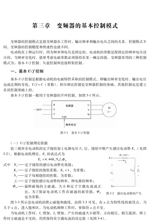
第三章 变频器的基本控制模式变频器的控制模式是指变频器在工作时,输出频率和输出电压之间的关系。
控制模式不同,变频器的控制精度和快速性也就不同。
电动机在工频运行时,因为频率和电压是固定的,电动机的参数是按固定的频率电压设计的,当频率变化时,就要考虑电磁参数必须保持在某一确定的值。
变频器常用的三种控制模式为:基本U/f控制、矢量控制和直接转矩控制。
一、基本U/f控制基本U/f控制是根据电动机的电磁特性采取的控制模式,即输出频率变化时,输出电压也成比例的变化,U/f=C(常数)。
恒压频比控制是变频器控制的基础,其他控制也是建立在该控制基础上的。
基本U/f控制一般用于变频器的开环控制,如图3 1所示。
图3 1 基本U/f控制(一)U/f控制理论依据给三相异步电动机的定子绕组加上电源电压U1后,绕组中便产生感应电动势E1(见图图3 2 感应电动势的产生3 2),根据电动机理论,E1的表达式为E1=4 44K1N1f1Φm式中 E1———定子绕组的感应电动势有效值;K1———定子绕组的绕组系数,K1<1,为常数;N1———定子每相绕组的匝数,为常数;f1———定子绕组感应电动势的频率,即电源的频率;Φm———旋转磁场的主磁通,大小和定子空载电流成正比,为了保证电动机工作在磁通的最佳值,Φm也为常数。
图3 3所示是电动机的铁心磁饱和曲线,由图3 3可见,在a点为特性线的最佳点,当大于a点,进入饱和区,当电动机调频工作时,要保持a点不变。
当电动机工作时,I1增加,I2增加,产生的磁通大小相等,方向相反,相互抵消,即工作时主磁通是不变的,仍然保持在空载电流的设定值(见图3 4)。
图3 3 电动机铁心磁饱和曲线图3 4 主磁通不变将上述常数带入公式,有E1=f1C,由于ΔU很小,当U1较高时,ΔU可忽略,有:U1≈E1=f1C上式可改写为U1/f1=C(常数)U1上升,f1上升;U1下降,f1下降。
即U1/f1=常数,这就是变频器的基本U/f控制模式。
丹佛斯传动主从控制的基本实现方式
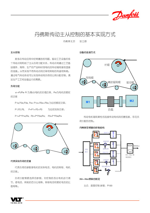
Hz Max re. 0 1 00% Hz Max re. 0 100%
转矩速度闭环
Min-Max频率的限定 主点:速度控制 参数:P100
从点:转矩控制/速度控制:P100 控制端子的连接: 从机:T18起停端子直接 接入T12(24V);避免进入速度模 式; 主机:主机的T18和从机的T27 :主机应有运行准备输出给从机的T37 安全 停车作为更好的连锁保证 端子控制和总线控制 主从间的I/O控制
设备的连接方式
伏辊
导网辊 辅助驱网辊 驱动辊
M1
负载
M2
P1=P*P1e/Pe; P2=P*P2e/Pe;
传动电机轴间柔性的连接传动电机间的硬连接,存在负 荷分配的控制。 丹佛斯变频器的控制结构
Hz Max re. 0 100%
速度开环
速度闭环
Hz Max re.
MAX
1 00% Hz
频率输出
控制 模式
避免轻载时转矩的控制的从机飞车,速度限幅可以来自 主机: Par: 100 : 速度控制闭环 Par. 221: 160% Par. 222: 160% Par. 319: +/-160% TORQ => 4-20mA (设定实际的转 矩输出值) SLAVE: Par. 100: 转矩控制 主点的运行速度。 速度和转矩控制模式的切换
从机控制模式:端子控制或总线选择菜单的切换,可以 运行中切换。 预防控制直流过压的措施
电机主从控制波形
140 120 100 80 Torque A Torque B Torque C Torque D Speed %
VLT &FC
81 82 88 89
VLT &FC
81 82 88 89
丹佛斯 AME 435 QM 调节控制执行器 规格书说明书

1SMT/SIVD.CV.S2.02 © Danfoss 09/2014Data sheetActuator for modulating control AME 435 QMActuatorType Supply voltage Code No.AME 435 QM24 VAC/DC082H0171DescriptionAME 435 QM actuator for modulating control is used with pressure independent balancing and control valve type AB-QM from DN 40 to DN 100. The actuator has some special features:• it automatically adapts its stroke to the valve end positions which reduces commissioning timeOrdering • valve flow adjustment feature; flow can be variably-adjusted from linear to logarithmic or opposite.• the advanced design incorporates load related ‘switch-off’ to ensure that actuators and valves are not exposed to overload Main data:• Nominal voltage (AC or DC): - 24 V, 50 Hz/60 Hz • Control input signal: - 0(4)-20 mA - 0(2)-10 V • Force: 400 N • Stroke: 20 mm • Speed (selectable):- 7.5 s/mm - 15 s/mm• Max. medium temperature: 120 °C • Self calibrating • LED signalling• External RESET button • Output signal • Manual operationTechnical dataAccessories-AdapterTypefor valve’s DNfor Actuator Code No.AB-QM adapter (2st generation)40-100AME 15 QM003Z0694AB-QM adapter (1st generation)AME 435 QM065Z0313Power supply V 24 AC/DC; ±10%Power consumption running VA 4,5standby1,2Frequency Hz 50/60Control input Y V 0-10 (2-10); Ri = 95 kΩmA 0-20 (4-20); Ri = 500 ΩOutput signal X V 0-10 (2-10); RL = 650 Ω (maximal load)Closing force N 400Max. stroke mm 20Speeds/mm 7,5 or 15Max. medium temperature °C120Ambient temperature0 … 55Storage and transport temperature –40 … 70Protection class II Grade of enclosure IP 54Weightkg 0,45- marking in accordance with standardsLow Voltage Directive (LVD) 2006/95/EC: EN 60730-1, EN 60730-2-14 EMC Directive 2004/108/EC: EN 61000-6-2, EN 61000-6-32VD.CV.S2.02 © Danfoss 09/2014SMT/SIData sheetActuator for modulating control AME 435 QMInstallationMechanicalNo tool is required to mount actuator on the valve. Installation of the valve with the actuator is allowed in horizontal position or upwards. Installation downwards is not allowed.The actuator must not be installed in anexplosive atmosphere, at ambient temperature lower than 0 °C or at ambient temperature higher than 55 °C. It must not be subject to steam jets, water jets or dripping liquid as well.Note:The actuator may be rotated up to 360° withrespect to the valve stem by loosening the retaining fixture. Once the actuator is placed, retighten the fixture.ElectricalElectrical connections can be accessed by removing the actuator cover. Two cable gland entries without thread (Ø16 and combined Ø16/Ø20) are prepared for cable glands. From factory one entry is provided by rubber cable gland and the other entry is prepared for opening. Note:Cable and cable gland used must not compromise the actuator’s IP rating, and must ensure the connectors are fully strain relieved.Rubber cable gland delivered from factory does not compromise IP rating but it does not provide fully strain relieve according to LVD directive.Please observe local rules and regulations as well.Complete the mechanical and electricalinstallation, set jumper and DIP-switches, then perform the necessary checks and tests:• Apply powerNote that the actuator will now perform automatic Calibrating function • Apply the appropriate control signal and check:- SW7 setting- the actuator drives the valve over the entire stroke length The unit is now fully commissioned.CommissioningAutomatic Calibrating featureThe actuator automatically adapts its stroke to the valve end positions :- when power is applied for the first time or - afterwards by pressing the STAND BY/RESET button for 5 seconds Testing entire valve stroke lengthThe actuator can be driven to the fully-open or closed positions by connecting SN to terminals 1 or 3.The actuator must be dismantled and the elements sorted into various material groups before disposal.Disposal3VD.CV.S2.02 © Danfoss 09/2014SMT/SIData sheetActuator for modulating control AME 435 QMEqual-percentage valve-flow adjustment (SW 7 in position ON )The actuator has a special valve-flowadjustment feature called alpha value. Actuator characteristics can be, by turning the alpha knob counter clockwise (CCW), variably-adjusted from α=1 (linear) to α=0.1.Jumper/DIP switch settingJumper• U/I - Input signal type selector- U position; voltage input is selected - I position; current input is selected Factory setting: jumper is in U position.DIP switchesFactory setting: all switches are in OFF position.• SW 1: Not used• SW 2: Input signal range selector- OFF position; the input signal is in the range from 0-10 V (voltage input) or from 0-20 mA (current input)- ON position; the input signal is in the range from 2-10 V (voltage input) or from 4-20 mA (current input)• SW 3: Direct or Inverse acting selector- OFF position; the actuator is in direct acting mode (stem extracts as voltage increases)- ON position; the actuator is in inverse acting mode (stem retracts as voltage increases)If used with AB-QM valves, SW 3 is recommended to be in OFF position (factory setting).• SW 4: Fast/Slow - Speed selector- OFF position; the actuating speed is 7.5 s/mm• SW 6: Not used• SW 7: LOG/MDF - Logarithmic or modified flow through valve selector- OFF position; .........LOG (α=0.2, factory setting)- ON position; ...........MDF (initial setting: α=1, linear)Explanation:If SW 7 is in OFF position, alpha knob is not activated. Turning alpha knob will not influence α value (α=0.2).If SW 7 is in ON position, α value can be manipulated using alpha knob. MDF initial setting of alpha knob is 1, which means linear setting. Regarding alpha knob setting In order to have optimal control, linearcharacteristics of system (valve, actuator, HEX) is required. This can be assured using theright α value. Appropriate α value depends on temperatures of heating/cooling medium and controlled temperature of heated/cooled medium. Calculate α value according to the Tech Note number VNHUA102 (Setting the right α value).4VD.CV.S2.02 © Danfoss 09/2014SMT/SIData sheetActuator for modulating control AME 435 QMLed signalling/Actuator operating modesLED function indicatorThe bi-colour (green/red) LED function indicator is located on the actuator cover. It indicates the operating modes.External buttonActuator has external STAND BY/RESET button which is located next to LED indicator. By pressing on this button different operating modes are initiated:• Calibrating modePressing the STAND BY/RESET button for 5 sec. causes the actuator to start Calibrating procedure :The bi-colour LED flashes green at 1 sec.intervals during calibration procedure, which begins by extracting the stem. When the maximum force is detected (at the end valve position), the actuator then retracts thestem, until the maximum force is once again detected (on the other valve end position). The actuator will then enter to normal mode and respond to the control signal.• Positioning modeThe bi-colour LED is green and stays onduring positioning of the actuator according to the control signal • Normal modeWhen the positioning of the actuator is finished the LED flashes green every 6 seconds.• STAND BY modePressing the STAND BY/RESET button switches the actuator to STAND BY mode. The actuator keeps its last position in this mode and does not react to any control signal. This mode can be used for manual operation during the commissioning of other equipment, or for service purposes.The bi-colour LED flashes red at 2 sec. intervals.After pressing the STAND BY/RESET button again actuator switches to normal mode.5VD.CV.S2.02 © Danfoss 09/2014SMT/SIData sheetActuator for modulating control AME 435 QMManual overrideManual override is done by means of control knob on actuator housing:• Disconnect power supply or press STAND BY/RESET button• Adjust valve position using the control knob (observe the rotation direction)When manual override is not needed:• Restore power supply or press STAND BY/RESET button again Remark:When the manual override has been used, the output signal (X) is not correct until the actuator reaches its end position.Wiring 24 VAC/DC onlySP 24 VAC/DC .............. Power supply SN0 V mon Y 0-10 V ........................Input signal (2-10 V) 0-20 mA (4-20 mA)X 0-10 V ........................Output signal (2-10 V)1, 3Override input signalThe actuator can be driven to the fully-open position by connecting SN to terminal 1 or fully-closed by connecting SN to terminal 3.Signal 1 can be connected to thermostat to prevent freezing and signal 3 can be connected to thermostat to prevent overheating.Wiring length Recommended cross-sectional area of the wiring 0-50 m0.75 mm 2> 50 m1.5 mm 2Important: AME 435QM can be used only for modulating control. For 3-point control useAMV 435 (082H0162/163). It is recommend to use modulating control with AB-QM.6VD.CV.S2.02 © Danfoss 09/2014SMT/SIData sheetActuator for modulating control AME 435 QMDimensionsActuator - valve combinations7VD.CV.S2.02 © Danfoss 09/2014SMT/SIData sheet Actuator for modulating control AME 435 QM8VD.CV.S2.02Produced by Danfoss A/S © 09/2014Data sheet Actuator for modulating control AME 435 QM。
丹佛斯(Danfoss)调试
丹佛斯VLT2800调试说明控制方式有以下几种:1. 变频器面板操作(参数20手动有效或无效)(1)002(本机/远程操作)修改为1。
(2)修改013值,将其改为本机开环控制[1]。
(3)同时按住[QUICK MENU ]和[+]键进入参数选择,按[+]选择参数20,按[CHANGE DATA]键进入参数,按[+]将参数20手动操作由0无效改为1有效后按[CHANGE DATA]键确认。
(4)按[QUICK MENU ]键退出参数选择.按[CHANGE DATA]键显示屏会显示Auto,按[+]将它改为Hand, 按[CHANGE DATA]键确认,按[+]选择所需频率,按START键就可以运行变频器。
2. 变频器电位器操作将变频器接线端子12,27短接后接入运行接触器常开触点的一端,将18接入接触器常开触点另一端,这样当接触器运行时,12,18,27三个点将被短接,变频器处于运行状态,将1K Ω电位器中间的抽头接入接线端子53,将顶端接入接线端子50,将底端接线端子55,在变频器处于运行状态旋转电位器即可调整频率.如需外接频率表,将频率表两端接入端子42,55上,并在两个端子上并接一个300Ω电阻, 同时按住[QUICK MENU ]和[+]键进入参数选择,按[+]选择参数319,按[CHANGE DATA]键进入参数,按[-]将参数319由7改为5,频率表选择5V,120HZ.3. 流程全电脑控制时外部4-20MA控制将4-20MA信号正端接入端子60,负端接入端子55, 将变频器接线端子12,27短接后接入运行接触器常开触点的一端,将18接入接触器常开触点另一端,这样当接触器运行时,12,18,27三个点将被短接,变频器处于运行状态, 同时按住[QUICK MENU ]和[+]键进入参数选择,按[+]选择参数314,按[CHANGE DATA]键进入参数,按[+]将参数314由0改为1,参数315由0.0改为4.0, 参数323由1改为10,在变频器处于运行状态时输入4-20MA信号即可调整变频器频率.4. 配料秤时快慢加料变频器控制将变频器接线端子12,27短接后接入快加料中间继电器KA1常开触点的一端和并接入慢加料中间继电器常开触点KA2的一端,将18接入快加料中间继电器KA1常开触点另一端,29接入慢加料中间继电器KA2常开触点另一端, 同时按住[QUICK MENU ]和[+]键进入参数选择,按[+]选择参数305,按[CHANGE DATA]键进入参数,按[+]将参数305由13改为22,参数215为快加料是频率设定值(该设定值为百分值,频率为该设定值*参数205所设的值,如205参数值为50HZ(变频器默认值),您想将快加料时频率设为50HZ,则需将参数215设为100),参数216为慢加料是频率设定值(该设定值也为百分值,频率为该设定值*参数205所设的值,如205参数值为50HZ(变频器默认值),您想将慢加料时频率设为10HZ,则需将参数216设为20),快加料时快加料中间继电器KA1吸合,慢加料时慢加料中间继电器KA2吸合。
VVC控制模式
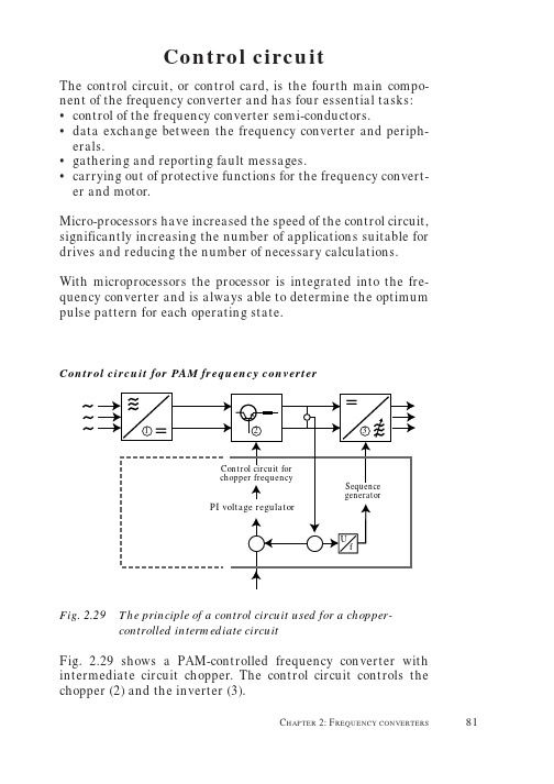
Control circuitThe control circuit, or control card, is the fourth main compo-nent of the frequency converter and has four essential tasks:•control of the frequency converter semi-conductors.•data exchange between the frequency converter and periph-erals.•gathering and reporting fault messages.•carrying out of protective functions for the frequency convert-er and motor.Micro-processors have increased the speed of the control circuit, significantly increasing the number of applications suitable for drives and reducing the number of necessary calculations. With microprocessors the processor is integrated into the fre-quency converter and is always able to determine the optimum pulse pattern for each operating state.Fig. 2.29The principle of a control circuit used for a chopper-controlled intermediate circuitFig. 2.29 shows a PAM-controlled frequency converter with intermediate circuit chopper. The control circuit controls the chopper (2) and the inverter (3).This is done in accordance with the momentary value of the intermediate circuit voltage.The intermediate circuit voltage controls a circuit that functions as an address counter in the data storage. The storage has the output sequences for the pulse pattern of the inverter. When the intermediate circuit voltage increases, the counting goes faster, the sequence is completed faster and the output frequency increases.With respect to the chopper control, the intermediate circuit voltage is first compared with the rated value of the reference signal – a voltage signal. This voltage signal is expected to give a correct output voltage and frequency. If the reference and intermediate circuit signals vary, a PI-regulator informs a cir-cuit that the cycle time must be changed. This leads to an adjustment of the intermediate circuit voltage to the reference signal.PAM is the traditional technology for frequency inverter control. PWM is the more modern technique and the following pages detail how Danfoss has adapted PWM to provide particular and specific benefits.Danfoss control principleFig. 2.30 gives the control procedure for Danfoss inverters.The control algorithm is used to calculate the inverter PWM switching and takes the form of a V oltage V ector C ontrol (VVC) for voltage-source frequency converters.VVC controls the amplitude and frequency of the voltage vector using load and slip compensation. The angle of the voltage vec-tor is determined in relation to the preset motor frequency (ref-erence) as well as the switching frequency. This provides:•full rated motor voltage at rated motor frequency (so there is no need for power reduction)•speed regulation range: 1:25 without feedback•speed accuracy: ±1% of rated speed without feedback •robust against load changesA recent development of VVC is VVC plus under which. The ampli-tude and angle of the voltage vector, as well as the frequency, is directly controlled.In addition to the properties of VVC , VVC plus provides:•improved dynamic properties in the low speed range(0 Hz-10 Hz).•improved motor magnetisation•speed control range: 1:100 without feedback•speed accuracy: ±0.5% of the rated speed without feedback •active resonance dampening•torque control (open loop)•operation at the current limitVVC control principleUnder VVC the control circuit applies a mathematical model, which calculates the optimum motor magnetisation at varying motor loads using compensation parameters.In addition the synchronous 60°PWM procedure, which is inte-grated into an ASIC circuit, determines the optimum switching times for the semi-conductors (IGBTs) of the inverter.The switching times are determined when:•The numerically largest phase is kept at its positive or nega-tive potential for 1/6of the period time (60°).•The two other phases are varied proportionally so that the resulting output voltage (phase-phase) is again sinusoidal and reaches the desired amplitude (Fig. 2.32).Fig. 2.31Synchronous 60°PWM (Danfoss VVC control) of onephaseUnlike sine-controlled PWM, VVC is based on a digital genera-tion of the required output voltage. This ensures that the fre-quency converter output reaches the rated value of the supply voltage, the motor current becomes sinusoidal and the motor operation corresponds to those obtained in direct mains connec-tion.Fig. 2.32With the synchronous 60°PWM principle the full output voltage is obtained directlyOptimum motor magnetisation is obtained because the fre-quency converter takes the motor constants (stator resistance and inductance) into account when calculating the optimum output voltage.As the frequency converter continues to measure the load cur-rent, it can regulate the output voltage to match the load, so the motor voltage is adapted to the motor type and follows load con-ditions.VVC plus control principleThe VVC plus control principle uses a vector modulation principle for constant, voltage-sourced PWM inverters. It is based on an improved motor model which makes for better load and slip compensation, because both the active and the reactive current components are available to the control system and controlling the voltage vector angle significantly improves dynamic perfor-mance in the 0-10 Hz range where standard PWM U/F drives typically have problems.The inverter switching pattern is calculated using either the SFAVM or 60°AVM principle, to keep the pulsating torque in the air gap very small (compared to frequency converters using synchronous PWM).The user can select his preferred operating principle, or allow the inverter to choose automatically on the basis of the heat-sink temperature. If the temperature is below 75°C, the SFAVM principle is used for control, while above 75°the 60°AVM prin-ciple is applied.Table 2.01 gives a brief overview of the two principles:The control principle is explained using the equivalent circuit diagram (Fig. 2.33) and the basic control diagram (Fig. 2.34).It is important to remember that in the no-load state, no current flows in the rotor (i ω= 0), which means that the no-load voltage can be expressed as:U = U L = (R S + j ωS L S ) ×i sTable 2.01Overview: SFAVM versus 60°AVMMax. switchingSelection frequency ofPropertiesinverter SFAVMMax. 8 kHz1.low torque ripple compared to the synchronous 60°PWM (VVC)2.no “gearshift”3.high switching losses in inverter60°-AVMMax. 14 kHz1.reduced switching losses in inverter (by 1/3compared to SFAVM)2.low torque ripple compared to the synchronous 60°PWM (VVC)3.relatively high torque ripple compared to SFAVMloaded)in which:R S is the stator resistance,i s is the motor magnetisation current,L Sσis the stator leakage inductance,L h is the main inductance,L S(=L Sσ+ L h) is the stator inductance, andωs(=2πf s) is the angular speed of the rotating field in the air gapThe no-load voltage (U L) is determined by using the motor data (rated voltage, current, frequency, speed).Under a load, the active current (i w) flows in the rotor. In order to enable this current, an additional voltage (U Comp) is placed at the disposal of the motor:The additional voltage U Comp is determined using the no-load and active currents as well as the speed range (low or high speed). The voltage value and the speed range are then deter-mined on the basis of the motor data.f f r e q u e n c y (i n t e r n a l )f sp r e s e t r e f e r e n c e f r e q u e n c y ∆fc a l c u l a t ed s l i p f re q u e n c y I S Xr e a c t i v e c u r r e n t c o m p o n e n t s (c a l c u l a t e d )I S Ya c t i v e c u r r e n t c o m p o n e n t s (c a l c u l a t e d )I S X 0, I S Y 0n o - l o a d c u r r e n t o f x a n d y a x e s (c a l c u l a t e d )I u , I v , I wc u r r e n t o f p h a s e s U , V a nd W (me a s u r e d )R ss t a t o r r e s i s t a n c e R rr o t o r r e s i s t a n c e θa n g l e o f t h e v o l t a g e v e c t o r s θ0n o - l o a d v a l u e t h e t a ∆θl o a d -d e p e n d e n t p a r t o f t h e t a (c o m p e n s a t i o n )T CT e m p e r a t u r e o f h e a t c o n d u c t o r / h e a t s i n kU D Cv o l t a g e o f D C i n t e r m e d i a t e c i r c u i t U Ln o - l o a d v o l t a g e v e c t o r U Ss t a t o r v o l t a g e v e c t o r U C o m pl o a d - d e p e n d e n t v o l t a g e c o m p e n s a t i o n U m o t o r s u p p l y v o l t a g e X hr e a c t a n c e X 1s t a t o r l e a k a g e r e a c t a n c e X 2r o t o r l e a k a g e r e a c t a n c e ωss t a t o r f r e q u e n c y L Ss t a t o r i n d u c t a n c e L S ss t a t o r l e a k a g e i n d u c t a n c e L R sr o t o r l e a k a g e i n d u c t a n c e i sm o t o r p h a s e c u r r e n t (a p p a r e n t c u r r e n t )i wa c t i v e (r o t o r ) c u r r e n tE x p l a n a t i o n s f o rF i g . 2.33 (p a g e 87) a n d F i g . 2.34 (p a g e 89)As shown in Fig. 2.34, the motor model calculates the rated no-load values (currents and angles) for the load compensator (I SX0, I syo) and the voltage vector generator (I o, θo). Knowing the actual no load values makes it possible to estimate the motor shaft torque load much more accurately.The voltage vector generator calculates the no-load voltage vec-tor (U L) and the angle (θL) of the voltage vector on the basis of the stator frequency, no-load current, stator resistance and inductance (see Fig. 2.33a). The resulting voltage vector ampli-tude is a composite value having added start voltage and load compensation voltage. The voltage vector θL is the sum of four terms, and is an absolute value defining the angular position of the voltage vector.As the resolution of the theta components (θ) and the stator fre-quency (F) determines the output frequency resolution, the val-ues are represented in 32 bit resolution. One (θ) theta compo-nent is the no load angle which is included in order to improve the voltage vector angle control during acceleration at low speed. This results in a good control of the current vector since the torque current will only have a magnitude which corre-sponds to the actual load. Without the no load angle component the current vector would tend to increase and over magnetise the motor without producing torque.The measured motor currents (I u, I v and I w) are used to calcu-late the reactive current (I SX) and active current (I SY) compo-nents.Based on the calculated actual currents and the values of the voltage vector, the load compensator estimates the air gap torque and calculates how much extra voltage (U Comp) is required to maintain the magnetic field level at the rated value. The angle deviation (∆θ) to be expected because of the load on the motor shaft is corrected. The output voltage vector is repre-sented in polar form (p). This enables a direct overmodulation and facilitates the linkage to the PWM-ASIC.The voltage vector control is very beneficial for low speeds, where the dynamic performance of the drive can be significant-ly improved, compared to V/f control by appropriate control of the voltage vector angle. In addition, steady stator performance is obtained, since the control system can make better estimates for the load torque, given the vector values for both voltage and current, than is the case on the basis of the scalar signals (amplitude values).Field-oriented (Vector) controlVector control can be designed in a number of ways. The major difference is the criteria by which the active current, magne-tising current (flux) and torque values are calculated.Comparing a DC motor and three-phase asynchronous motor (Fig. 2.35), highlights the problems. In the DC, the values that are important for generating torque – flux (Φ) and armature current – are fixed with respect to size and phase position, based on the orientation of the field windings and the position of the carbon brushes (Fig. 2.35a).In a DC motor the armature current and flux-generating cur-rent are at right angles and neither value is very high. In an asynchronous motor the position of the flux (Φ) and the rotor current I 1depends on the load. Furthermore unlike a DC motor,the phase angles and current are not directly measurable from the size of the stator.Using a mathematical motor model, the torque can, however, be calculated from the relationship between the flux and the statorcurrent.ΦΦΦUI I ΦM ~ I × Φ × sinßG I a)b)Fig. 2.35Comparison between DC and AC asynchronous machines DC machine Simplified vector diagram of asyn-chronous machine for one load pointThe measured stator current (I S ) is separated into the compo-nent that generates the torque (I L ) with the flux (Φ)at right angles to these two variables (I B ). These generate the motor flux (Fig. 2.36).Using the two current components, torque and flux can be influ-enced independently. However, as the calculations, which use a dynamic motor model, are quite complicated, they are only financially viable in digital drives.As this technique divides the control of the load-independent state of excitation and the torque it is possible to control an asynchronous motor just as dynamically as a DC motor – pro-vided you have a feedback signal. This method of three-phase AC control also offers the following advantages:•good reaction to load changes •precise speed regulation •full torque at zero speed •performance comparable to DC drives.T ~ I S × ΦL × sin θUFig. 2.36Calculation of the current components for field-orientedregulationω:Angular velocity I S :Stator current I B :Flux-generating current I W :Active current/rotor current ΦL :Rotor fluxV/f characteristic and flux vector controlThe speed control of three-phase AC motors has developed in recent years on the basis of two different control principles:normal V/f or SCALAR control, andflux vector control.Both methods have advantages, depending on the specific requirements for drive performance (dynamics) and accuracy.V/f characteristic control has a limited speed regulation range of approximately 1:20 and at low speed, an alternative control strategy (compensation) is required. Using this technique it is relatively simple to adapt the frequency converter to the motor and the technique is robust against instantaneous loads throughout the speed range.In flux vector drives, the frequency converter must be config-ured precisely to the motor, which requires detailed knowledge. Additional components are also required for the feedback signal.Some advantages of this type of control are:•fast reaction to speed changes and a wide speed range •better dynamic reaction to changes of direction•it provides a single control strategy for the whole speed range.For the user, the optimum solution lies in techniques which combine the best properties of both strategies. Characteristics such as robustness against stepwise loading/unloading across the whole speed range - a typical strongpoint of V/f-control - as well as fast reaction to changes in the reference speed (as in field-oriented control) are clearly both necessary.Danfoss VVC plus is a control strategy that combines the robust properties of V/f control with the higher dynamic performance of the field-oriented control principles and has set new standards for drives with speed control.VVC plus Slip compensationIndependently of the actual load torque, the magnetic field strength of the motor and the shaft speed are maintained at the speed reference command value. This is done using of two equal-ising functions: slip compensation and the load compensator. The slip compensation adds a calculated slip frequency (∆f) to the rated speed signal in order to maintain the required refer-ence frequency (Fig. 2.31). The rise in stator frequency is limit-ed by a user-defined run-up time (ramp). The estimated slip val-ue is taken from the estimated value of the torque load and the actual magnetic field strength – so the magnetic field weaken-ing is also taken into consideration.The stationary behaviour of the control system is illustrated together with the torque/speed graphs in Fig. 2.37.20002102024[Nm]1000200030004000[rpm]Fig. 2.37Torque/speed characteristics (Rated torque 10 Nm)。
丹佛斯变频器多重菜单应用案例

丹佛斯变频器多重菜单应用案例
某酒店引入了丹佛斯变频器系统,希望通过多重菜单应用提升酒店的服务质量和客户满意度。
以下是该酒店应用丹佛斯变频器系统的多重菜单案例:
1. 客房智能控制菜单:
客人可以通过酒店手机App或者客房电视上的多重菜单应用来调节空调、照明和窗帘等设备。
他们可以根据自己的需求设定温度、亮度和窗帘开合程度,提高客人的舒适度,同时也节约能源。
2. 酒店健身房设备菜单:
健身房配备的器械设备连接到丹佛斯变频器系统,并通过多重菜单应用进行控制。
客人可以根据自身身体状况和需求,选择适合自己的运动项目和强度。
菜单应用还可以提供健身指导和运动记录,帮助客人科学地锻炼身体。
3. 餐厅订餐菜单:
酒店的餐厅提供了多重菜单应用来点餐和预订。
客人可以通过手机App或者电视屏幕上的菜单应用选择菜品、填写用餐人数和时间。
这样,客人在到达餐厅时,食物已经准备好,节省了等待时间,方便了客人。
4. 会议室预定菜单:
对于需要使用会议室的客人,酒店提供了多重菜单应用来预定会议室。
客人可以通过手机App或者电视屏幕上的菜单应用选择会议室、填写使用时间和参会人数等信息。
菜单应用还可以提供会议设备的控制和预约服务,方便客人使用会议室进行商务活动。
通过丹佛斯变频器系统的多重菜单应用,该酒店提高了客户的满意度和服务质量,同时也提高了工作效率和节约了能源成本。
丹佛斯变频器中控远程控制和现场端子控制方案解决

丹佛斯中控远程控制和现场端子控制方案解决济南创恒科技发展有限公司满建江工业现场使用变频器时,往往要求变频器实现远程和现场控制。
远程控制时,由中控DCS 给定启停信号和速度信号,同时变频器反馈运行状态和速度值。
现场控制时,可通过现场按钮和电位器进行启停,速度给定操作。
这样就要求变频器在不同的操作状态时,接受不同的信号。
通常DCS给定4-20mA电流信号作为中控给定,现场电位器可变换0-10V电压信号作为现场给定。
丹佛斯各系列变频器,可通过多重菜单快捷的实现远程/现场控制功能,下面简单介绍丹佛斯FC300系列是如何通过菜单转换实现远程/现场转换的。
图1 变频器端子接线图如图1 端子18为启动功能,端子19为菜单转换0功能,端子53为现场模拟给定电压信号,端子54为DCS模拟给定电流信号,继电器1是变频器运行反馈信号,继电器2是变频器故障反馈信号,端子42为速度模拟量输出反馈信号。
改变19端子的状态即可轻松进行远程/现场控制功能的切换。
参数设定如下:菜单编辑菜单1 编辑菜单20-10有效菜单9多重菜单9多重菜单0-11编辑菜单1菜单1 2菜单2120-125电动机参数按电机铭牌设定按电机铭牌设定3-15参考源1 1模拟量53 2模拟量543-16参考源2 0无功能0无功能3-17参考源3 0无功能0无功能5-11 19端子功能23菜单位0 23菜单位05-12 27端子功能0无功能0 无功能540继电器1功能6运行/无故障6运行/无故障540继电器2功能10报警/警告10报警/警告610端子53低电压0V 4mA611端子53高电压10V 20mA6-14 53参考/反馈值低0 06-15 53参考/反馈值高1500 1500650端子42功能137速度4-20mA 137速度4-20mA最后设定完毕后将0-11改为有效菜单。
参数设定完毕后,在现场12,19端子未闭合是由模拟量53给定,闭合时为模拟量54给定,启动都是18端子控制。
丹佛斯变频器协议控制汇总及应用例程
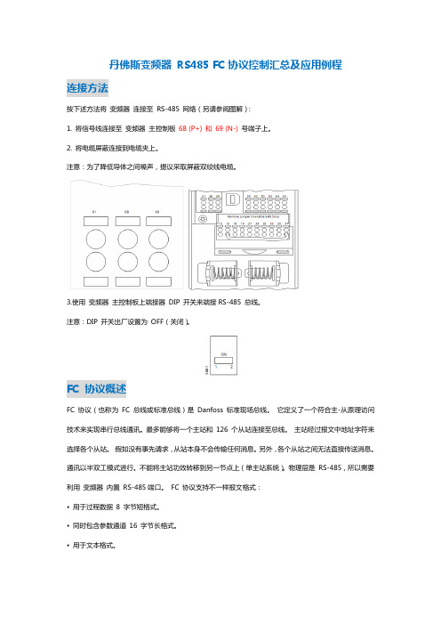
丹佛斯变频器RS485 FC协议控制汇总及应用例程连接方法按下述方法将变频器连接至RS-485 网络(另请参阅图解):1. 将信号线连接至变频器主控制板68 (P+) 和69 (N-) 号端子上。
2. 将电缆屏蔽连接到电缆夹上。
注意:为了降低导体之间噪声,提议采取屏蔽双绞线电缆。
3.使用变频器主控制板上端接器DIP 开关来端接RS-485 总线。
注意:DIP 开关出厂设置为OFF(关闭)。
FC 协议概述FC 协议(也称为FC 总线或标准总线)是Danfoss 标准现场总线。
它定义了一个符合主-从原理访问技术来实现串行总线通讯。
最多能够将一个主站和126 个从站连接至总线。
主站经过报文中地址字符来选择各个从站。
假如没有事先请求,从站本身不会传输任何消息。
另外,各个从站之间无法直接传送消息。
通讯以半双工模式进行。
不能将主站功效转移到另一节点上(单主站系统)。
物理层是RS-485,所以需要利用变频器内置RS-485端口。
FC 协议支持不一样报文格式:•用于过程数据8 字节短格式。
•同时包含参数通道16 字节长格式。
•用于文本格式。
(1) PKE占用两个字节,包含参数命令类型和参数数目;(2) IND为索引,也占用两个字节,索引字节用于表明它是一个读命令还是写命令。
在读命令中必需含有0400H格式,在写命令中必需含有0500H格式;(3) PWE为参数值块。
占用四个字节,分为高字(PWE H)和低字(PWE L)。
“比如主机要改变目前变频器参数,新参数就应写在参数PWE中发送给变频器;”(4) PCD为过程块,占用4个字节。
它有两种状态,当主机发给从机时,PCD1为控制字,PCD2为参考值;当从机发给主机时,PCD1为状态字,PCD2为目前输出频率;(5) BCC为数据控制字节。
由它来对接收到命令进行检验正确是否。
它初始值为0,然后对该字节以前全部字节进行异或。
stx lge adr pke ind pweh pwel pcd1 pcd2 BCC02 0E 04 0000 0000 0000 0000 0000 0000 XXFC协议控制字描述(PCD1)开启变频器:047C15 14 13 12 11 10 9 8 7 6 5 4 3 2 1 0 0 0 0 0 0 1 0 0 0 1 1 1 1 1 0 0停止变频器:047415 14 13 12 11 10 9 8 7 6 5 4 3 2 1 0 0 0 0 0 0 1 0 0 0 1 1 1 0 1 0 0FC 协议状态字描述060715 14 13 12 11 10 9 8 7 6 5 4 3 2 1 0 0 0 0 0 0 1 1 0 0 0 0 0 0 1 1 1电报结构每个报文全部含有下列结构:1. 起始字符(STX)=02 Hex2. 一个字节指明报文长度(LGE)3. 一个字节指明变频器地址(ADR)再以后是若干数据字节(数量不定,具体取决于电报类型【过程类型、参数类型、文本类型】)。
丹佛斯压差控制阀说明书

丹佛斯压差控制阀说明书丹佛斯压力开关KP系列的安装及使用众所周知,在一般的制冷系统中,都会用到高低压力开关,用来控制压缩机的启停、风机启停,从而确保制冷系统的正常运行。
今天和大家简单的交流一下压力开关KP的安装和使用。
KP的安装在托架上或者在纯平表面上安装KP压力控制器。
也可以在压缩机上安装压力控制器。
在不利条件下,角铁托架可能会增强安装平面的振动。
因此在出现强烈振动的地方应始终使用墙装托架。
如果有出现水滴或水雾的风险,则必须使用附带的顶板。
顶板可将外壳的防护等级增加到IPIP 44并且适用于所有的KP压力控制器。
要达到IP 44的防护等级,必须将控制器安装在角铁托架(060-105666)或墙板托架(060-105566)上来盖住其背板上的孔。
包含自动复位功能的所有装置均配有顶板。
带有手动复位的装置也可以使用顶板,但在这种情况下,必须单独购买(单压,代码为060-109766;双压,代码为060-109866)。
如果装置要用在污浊的条件下或者暴露在浓重的水雾中—从顶部或从侧面—则必须安装防护帽。
防护帽可与角铁托架或墙装托架一起使用。
如果装置存在暴露在多水环境中的风险,则当产品安装在特殊IP55外壳中后可达到更高的防IP 55护等级。
IP 55外壳有单压(060-033066)和双压(060-035066)可供选择。
控制器的压力管连接必须始终以正确的方式安装到管路上,即使液体不会聚积在波纹管底部。
尤其是在以下情况下,很可能会出现该风险:装置位于很低的周围环境中时,例如在气流中在管路的底部进行连接时。
这样的液体可能会损坏高压控制器。
因此,压缩机的振动得不到抑制并可能引发触点颤动。
放置多余的毛细管如果发生振动,多余的毛细管可能会破裂并导致失去所有的系统充注物。
因此遵守以下原则便显得非常重要:当直接安装在压缩机上时:固定毛细管,使压缩机/控制器装置作为一个整体一起振动。
必须盘起并扎紧多余的毛细管。
注意:根据EN规则,禁止使用毛细管来连接安全压力控制器。
丹佛斯恒温阀控温原理
丹佛斯恒温阀控温原理嘿,你有没有想过,在寒冷的冬天或者炎热的夏天,家里的温度是怎么被精准控制的呢?今天呀,咱就来唠唠丹佛斯恒温阀的控温原理,这可真是个超有趣的事儿呢!我有个朋友叫小李,他对这些东西就特别好奇。
有一次,他跑到我家,看到我家安装的丹佛斯恒温阀,就像发现了新大陆一样。
他眼睛瞪得大大的,问我:“这小玩意儿是怎么把温度控制得这么好的呢?”我当时就乐了,心想这可得好好给他讲讲。
你看啊,丹佛斯恒温阀就像是一个超级聪明的小管家。
它的身体里有个特别敏感的感温元件,这个感温元件呀,就像是我们人体的皮肤一样,能感知周围环境的温度变化。
当室内温度发生变化的时候,这个感温元件就开始工作啦。
比如说在冬天,我们想要房间保持在20度左右。
如果房间温度低于20度了,就像一个冷得直打哆嗦的人一样,这时候恒温阀里的感温元件就察觉到了。
它就会像发出信号的小信使一样,把这个“冷”的消息传递给恒温阀的控制部分。
这控制部分就像恒温阀的大脑一样,收到消息后,立马就开始想办法解决问题。
它会让热水更多地流入散热器,就好像给散热器加油打气一样,让散热器散发更多的热量。
这就好比我们冷的时候,多穿几件衣服来保暖。
我给小李解释到这儿的时候,他似懂非懂地点点头,又问我:“那要是夏天呢?这恒温阀也能控制温度吗?”我拍了拍他的肩膀说:“那当然啦!”夏天的时候,要是房间温度高于我们设定的温度了,感温元件又像个机灵的小侦探一样发现了这个情况。
然后告诉恒温阀的控制部分,这控制部分呢,就会减少热水流入散热器,甚至可能会让冷水流进去,就像是给房间喝了一杯凉水,让房间凉快下来。
这多神奇呀,就好像这个恒温阀能根据房间的冷热需求随时做出调整。
再深入一点说,丹佛斯恒温阀的内部结构其实是很精密的。
它里面的一些小零件之间的配合就像一个默契的小团队一样。
比如说,阀门的开合程度是和感温元件以及控制部分紧密相连的。
阀门就像是一扇门,温度的调节就像控制这扇门开合的大小。
如果要让温度升高得快一点,那这扇“门”就开得大一点,热水就像潮水一样涌进来;要是温度差不多了,这扇“门”就关小一点,热水的流入量就减少了。
- 1、下载文档前请自行甄别文档内容的完整性,平台不提供额外的编辑、内容补充、找答案等附加服务。
- 2、"仅部分预览"的文档,不可在线预览部分如存在完整性等问题,可反馈申请退款(可完整预览的文档不适用该条件!)。
- 3、如文档侵犯您的权益,请联系客服反馈,我们会尽快为您处理(人工客服工作时间:9:00-18:30)。
丹佛斯AK2-255系统使用说明书目录第一章系统介绍AK2-255网络综述―――――――― 2 系统功能―――――――――――― 3 部件介绍―――――――――――― 4第二章现场硬件连接指引硬件安装及连接网络――――――― 6第三章AK2-255设置简要说明操作界面使用说明―――――――― 8 控制器参数设定――――――――― 11 制冷系统的设置――――――――― 12 报警设置―――――――――――― 26 制冷系统运行状态一览及运行维护― 30第一章系统介绍AK2-255网络综述AK2-255控制系统由AK2主控制器、AK2通讯模块和功能模块组成,可根据客户控制要求灵活搭配组合。
一个AK2-255系统可由不超过5个AK2组成主网络,主控制器之间通过RS485进行通讯,可以自由选择使用电话调制解调器或以太网Modem实现远程通讯。
客户可在办公室内对卖场中的整个运行系统进行监控,如需要,还可以对设定参数进行调整,真正做到轻松管理。
上图为由多个AK2-255控制器组成的主控制器网络图示单独一个AK2-255主控制器与AK2通讯模块和功能模块组成现对独立的控制网络,参见上图。
AK2-255与AK2通讯模块连接建议采用TP78K带屏蔽的双绞线。
所有的通讯线和电源线只需连接到通讯模块上,通讯模块后的功能模块可实现拼接无需额外的线体连接,减少安装时的工作量,降低故障发生率。
AK2-255系统可以对制冷、空调和灯光系统进行智能化控制,实现对卖场或指定区域的集中集成控制。
具体功能如下:制冷控制 5个吸气组控制•每个吸气组最多可配置8台压缩机•每台压缩机最多4级卸载•每个吸气组可以加入一个变频器控制•每台吸气组最多可以控制40个制冷回路(冷库&冷柜)•每个制冷回路最多可有15个温度控制点•可控制5个过冷回路•可控制5个冷凝器(风冷或水冷)•每个冷凝器最多可控制12个风扇(风冷式)•冷凝风扇可由变频器控制空调控制最多可达40个系统控制(类型包括AHU、RTU、RTC和风机盘管单元)•采用RO、VO、SI和OI板直接控制•2速风扇控制•每个空气处理器可有6级冷却控制•每个空气处理器可有5级加热控制•模拟气阀控制•可分为5级除湿,包括干燥系统除湿方式•风阀控制•可实现多级压缩机控制•对压缩机和冷凝器控制可选配的RTC控制 RTC:屋顶式空调控制器•1级风扇控制•3级加热控制•3级制冷控制•1级风阀或节能控制灯光控制退出键确认键字母/数字键翻页键方向键切换键 编辑键• AK2-255主控制器AK2-255主控制器是网络中的控制设备,所有的设定参数,运行计算都是在AK2-255中完成的,用户可直接在AK2-255控制上浏览整个控制系统的运行情况,并利用控制器自带的键盘对参数进行修改。
• AK2系列输入输出模块AK2-255网络通过AK2输入模块可接收系统需要收集的标准检测量,在主控制器中对接收到的参数和设定值之间进行比较,根据程序设定的逻辑关系给出控制信号,通过AK2输出模块控制继电器动作,实现控制功能。
•AK2输出模块➢8个继电器输出•AK2输入输出模块具有以下特点–紧凑,性价比高–模块化–不需要对每个模块都接线–I/O 模块是自动分址的–Echelon® LonTalk® 协议第二章 现场硬件连接指引硬件安装1、AK2-255主控制器的安装 AK2-255主控制器的安装形式 AKC55主控制器有两种形式,例图上的AK2-255为盒式安装,面板式安装主控制器的各位置布局与之略由不同 AK2-255主控制器的接线 AK2-255主控制器与通讯模块屏蔽双绞线的连接接口 主控制器与以太网连接接口 主控制器与电脑连接接口 主控制器与调制解调器连接接口 主控制器与主控制器连接接口主控制器电源接口 主控制器地址设置旋钮 AK2-255控制器的地址设定 AK2-255控制器的地址出厂设定为“0”。
如果网络中有一个以上的AK2-255组成,则主控制器的地址必须依次从“0”开始,“1”,“2”依此类推。
地址的改动用螺丝刀来旋动红色的地址设置旋钮来设定2、AK2 输入输出模块的安装I/O通讯模块的电源连接传感器的连接A2+A1-A1+压力传感器接线黑线:GND白线:SIG红线:+12V温度传感器接线(无极性之分)第三章 AK2-255设置简要说明一、操作界面使用说明键盘操作名称功能说明0~9数字键设定及修改系统参数时用于输入参数值箭头方向键1.界面浏览时,在不同条目中移动光标2.下拉式多选项条目中,移动选择项Enter(确认)键确认所作出的选择、参数设定或修改值;如果参数设定或修改后没有按确认键,数值将无法生效+/-键1.参数值的正负性设定2.光标移动到需要输入或修改的参数位置时,利用此键激活开始输入或修改功能ESC(返回)键在不同界面浏览时,利用此键返回上一层界面MENU(主菜单)键无论在何界面,按下此键即可直接返回到主菜单界面中PG UP/ PG DN(翻页)键浏览界面时,若有多页信息,用于不同页面间转移中英文对照主菜单界面•Refrigeration制冷:关于制冷系统(压缩机组,制冷支回路,冷凝风扇等)的运行状态、参数输入及修改均由此条目进入•Authorization密码:此条目下,输入授权使用的用户名及密码后即可拥有对应级别的设定或修改权限•Alarms警报:可浏览当前正在发生的报警内容并更改报警设定条件•Communications通讯:显示主控制器间(AK2-255数量>1个时),主控制器与通讯模块,通讯模块与功能模块之间的通讯状态,可利用扫描网络功能检查通讯•Configuration设置:设定制冷、空调、灯光和其他应用的所有参数•History历史记录:设定及浏览用户指定的数据点的历史纪录,包括温度、压力、继电器动作及开关量输入记录。
功能权限登录•使用AK2-255时,如果只是对机组、蒸发器等受控设备状态进行浏览,则不需获得任何授权均可进行;但如果要对参数值进行调整或修改,用户会被要求登入帐户和密码信息。
参见上图•当完成设定或修改,退出权限时,移动光标到Log Out(退出登录)按下确认键即可回复到“浏览状态”二、控制器参数设定1、将英文菜单转为中文菜单AK2-255 控制器初始界面进入 Store Info 菜单在 Store Info 菜单中可以设置:1、商店名称(Store Name)2、时钟(Store Clock)2、语言设置(Units/Languages)(进入 Units/Languages 菜单)在Units/Languages菜单中可以设置:1、压力单位2、温度单位3、日期显示(进入 Language 菜单)三、制冷系统的设置 1、增加机组在Language 菜单中按EDIT 键把 Display 中的English 改成 Chinese 。
同时,选择 Set All 。
把所有菜单改变成中文界面。
到此为止,已将所有界面改成中文。
如需将中文改成英文,请重复次操作并选择 English 。
进入“设置”菜单进入“制冷”菜单选择“增加机组”设置“并联机组标识”设置是否有缺相监测,如没有请选择“否”2、设置回气组信息选择并进入“回气组信息”设置“回气组标识”设置“目标压力值”设置“安全切断压力值”设置“自适应吸气控制”为“动态”设置“压力浮动”与“夜间回置”参数,注意回置开始及结束时间的设定3、设置压缩机信息设置“压缩机数量”设置每台“压缩机容量”,请正确输入压缩机匹数设置“吸气温度监测”为“是”选择并进入“压缩机”设置“中央区域控制”参数设置“油压监控”相关参数设置压缩机排气温度及排气压力相关参数设置系统“能量分级方式”,一般情况选择“自动”,如需手动则需要进行能量分级等大小压缩机可以设置均时运行 油压监控设置排气温度、压力保护的设置4、设置蒸发器信息选择并进入“蒸发器”在此进行冷柜、冷库的详细设定设置系统“制冷回路数量”,一般情况制冷回路数量与此系统中需要控制的电磁阀数量一致。
“自动设置除霜时间表”在“激活”状态下,所有制冷回路会自动生成除霜时刻表。
如选择“禁用”则需要手动输入每个制冷回路的除霜时刻。
1、选择并进入每个制冷回路的“设置”2、设备类型可以进行多项选择:“冷柜”、“多层柜”“单体冷柜”、“岛柜”与“其它”3、“制冷回路”可以根据客户需要进行名称编辑4、冷柜/冷库温度传感器数量设定(除霜温度传感器除外)5、设定冷柜/冷库的控制温度目标值与偏差值6、如是电加热除霜则选择“电加热”否则选择“时间控制”7、如冷柜/冷库有除霜温度传感器则选择“除霜中止类型”,如没有则选择“送风传感器”8、冷柜/冷库温度控制通常选择“平均值”而除霜中止通常选择“所有”设置“最短除霜时间”与是否有“防结露控制”设置除霜过程中“风扇控制”相关参数设置单个制冷回路“除霜次数”及“除霜时刻表”。
如除霜时刻表被“激活”,则时刻表无法手动更改。
“包括在吸气浮动功能中”选择“是”设置“低温报警”与“高温报警”详细参数,及报警延时时间。
过冷器设置“过冷器”参数的设置也在“蒸发器”菜单中进行。
选择“类型”为“过冷器”并进入“设置”设置“电磁阀数量”与控制“级数”及每级过冷器开启温度与关闭温度5、设置冷凝器信息选择并进入“冷凝器”在此进行冷凝器的详细设定“冷凝器类型”选择风冷式风扇可设置为“一对”控制,也可以设置为“单个”控制“目标值”为冷凝器风扇开启值如风扇有变频控制,可以对变频控制进行设置分液式冷凝器设置6、地址设置选择并进入“地址设置”在此进行“继电器输出地址”,“传感器输入地址”与“开、关量输入地址”等的详细设定在“继电器输出”页面进行继电器地址的设置,注意地址的设置要与实际接线准确对应,同时进行“常开”、“常闭”选择。
控制器默认值为“常闭”中央区域控制及反应时间设定7、安全报警的设置选择并进入“地址设置 ”在此进行“继电器输出地址”,“传感器输入地址”与“开、关量输入地址”等的详细设定在“继电器输出”页面进行继电器地址的设置,注意地址的设置要与实际接线准确对应,同时进行“常开”、“常闭” 选择。
控制器默认值为“常闭”选择并进入“设置”中的“其它 ” 在此进行“压缩机安全报警”,“油压报警”与“缺相报警”等的详细设定选择并进入“其它”菜单下的“开/关量输入”\ 在此设定开/关量输入信号的数量并准确设定开/关量输入信号的地址,并设定为“关闭”选择并进入“其它”菜单下的“报警”选择并进入“其它报警”菜单下的“开/关量输入”。
进入需要设定报警相应的菜单设定“Number of alarms”的数量为1。
如果,为开路报警,则选择“如果开”如果,为闭路报警,则选择“如果关”把时间延时设置为“0”选择开关量输入7、柜体灯光设置选择开关量输入选择并进入“设置”中“其它”菜单下的“逻辑表达式” 根据控制要求设定“算法”在此设定了两个“时间表”逻辑,分别在不同时间要求下开启/关闭灯光 “逻辑类型”需设定为“时间表”并设定要求的控制时间。