E调试软件IEcout使用说明
E(X)系列BRAIN协议变送器调试手册

DPharp BRAIN 通讯类型
(EJXA, EJAE)
IM 01C25T03-01E
IM 01C25T03-01E
6th Edition
i
DPharp BRAIN 通讯类型
IM 01C25T03-01E 第 6 版
目录
1. 简介.............................................................................................................. 1-1
关于本手册...................................................................................................................... 1-1 1.1 1.2 本产品的安全使用................................................................................................ 1-1 保修...................................................................................................................... 1-2
3.
操作.............................................................................................................. 3-1
3.1 BT200 操作程序................................................................................................... 3-1 3.1.1 3.1.2 按键布局和屏幕显示........................................................................... 3-1 操作按键的功能.................................................................................. 3-1 (1) 字母数字键和 Shift 键................................................................. 3-1 (2) 功能键......................................................................................... 3-2 3.1.3 3.1.4 使用操作键调用菜单地址................................................................... 3-3 打印输出(对于 BT200 打印机选项)............................................... 3-3 (1) 所有参数的打印输出.................................................................. 3-3 (2) 通过菜单项打印输出.................................................................. 3-3 3.2 使用 BT200 设置参数 ......................................................................................... 3-4 3.2.1 3.2.2 3.2.3 参数使用和选择.................................................................................. 3-4 菜单树................................................................................................. 3-5 设置参数.............................................................................................. 3-6 (1) 位号设置 .................................................................................... 3-6 (2) 校正量程设置............................................................................. 3-6 (3) 阻尼时间常数设置...................................................................... 3-7 (4) 输出模式和内置显示表显示模式设置 ....................................... 3-8 (5) 输出信号低切模式设置............................................................... 3-8 (6) 内置显示表标度设置.................................................................. 3-9 (7) 显示温度单位设置.................................................................... 3-11 (8) 工作模式设置........................................................................... 3-11 (9) 引压管连接方向设置 ............................................................... 3-11
意科IECCO 安装调试指南(690V)

P001 ACCESS LEVEL Engineer
[CFG] EEPROM
步骤三 年
4 按 ENTER 键 进 入 EEPROM 控 制 参 数 设 定 界 面。按上翻()或下翻键,找 到 需 要 设 置 参 数 Restore Deault。按下 ENTER ,保存。 后按 ESC 推出键逐级的返 回。
取直流母线+ - 的电压,是否为 0
2.为了防止在拆装的过程中由于人体的的静电损坏设备里的晶体管 模块,进行操作的人员必须穿着静电衣和带防静电手腕
步骤一:取下控制面板,把与主板的连接线分开
注意:从变频器主板端拔下控制面板,不要拉扯。 步骤 2:取下控制端子盖板和上盖板
从这里取下 面板
步骤 3:取下控制端子盖板
• 功能调试,指用户按照具体生产工艺的需要进行的设置操作。这一 部分的调试工作比较复杂,常常需要在现场多次调试。
以下将按照这三个步骤,通过案例介绍和相关参数的说明,逐步的介 绍全部SINUS 变频器的调试流程。
参数设置 参数复位:
参数复位,将变频器的参数恢复到出厂时的参数默认值。在变 频器初次调试,或者参数设置混乱时,需要执行该操作,以便于将变 频器的参数值恢复到一个确定的默认状态。
IFD MEA
STAR T 0 rmp 1400 rmp
PAR CF [IDP]
[IDP] PRODUCT
3. 按 上 翻 或 下 翻 键 , 切 换 到 语言参数,按 ENTER 键进入, 选择英语,按 ENTER 保存 后按 ESC 推出
Language English
步骤二 电机配置参数和变频器参数的配置。 (我们前面已经列出了修改参数的操作步骤,这一章节就不详细说
REF 源的设置需要设置下列参数 SINUS-PENTA ,一共提供了四路的参考源输入通道,默认的情况
智能温控表使用说明书

KKAI208C02A-A/0-201611234:(48*48)6:(96*48)7:(72*72)8:(48*96)9:(96*96)80:(80*160)16:(160*80)484872969616080A 型号H(Min)GBCDEF J 48967248968016097.597.597.597.597.596966.5999913139188.588.588.588.5838345.54567.59292155.5762525252525303045.59267.5459276155.54589.56744.591.575.5155K (Min)25252525253030面板尺寸 侧面尺寸 开孔尺寸J-0+0.5AI208系列E:版本10:单路输入B:一路报警输出 C: 两路报警 A: 无报警功能4: 48W*48H*100L 6:48W*96H*100L 7:72W*72H*100L 8:96W*48H*100L 9:96W*96H*100L AI208系列温控表R:继电器输出 S: 固态继电器输出 K:可控硅输出(需订做)序号型号主控方式2121报警路数1234SSR SSR RELAY RELAYAI208-4/6/7/8/9-SC10AI208-4/6/7/8/9-SB10AI208-4/6/7/8/9-RC10AI208-4/6/7/8/9-RB10智能温控表使用说明书本说明书对温控表设置、配线及各部分名称等进行说明,使用本产品前,请认真阅读本说明书,在理解内容的基础上正确使用。
并请妥善保存,以便需要时参考。
⊙支持多种热电偶、热电阻信号类型⊙采用模糊PID 控制算法,且自整定无过冲⊙多种控制方式可选,具体请参照OT 参数⊙RUN/STOP,运行/停止功能一键切换特点2、隔离模式框图:固态继电器输出绝缘电阻静电放电脉冲群抗扰度浪涌抗扰度电压暂降及短时中断抗扰度隔离耐压DC 24V 脉冲电平,带载<30mA 输入、输出、电源对机壳>20MΩIEC/EN61000-4-2 Contact ±4KV /Air ±8KV perf.Criteria B IEC/EN61000-4-4 ±2KV perf.Criteria B IEC/EN61000-4-5 ±2KV perf.Criteria BIEC/EN61000-4-29 0%~70% perf.Criteria B信号输入与输出及电源1500VAC 1min,60V 以下低压电路之间DC500V,1min 整机重量约 400g机壳材质面贴材质停电数据保护面板防护等级安全标准外壳与面板基架PC/ABS (难燃度UL94V-0)PET(F150/F200)10年,可写数据次数100万次IP65(IEC60529)IEC61010-1 过电压分类Ⅱ,污染等级2,等级Ⅱ(加强绝缘)3、测量信号参数表:1、电气参数表:采样速度2次每秒供电电源继电器容量AC 250V /3A 额定负载寿命大于10万次AC/DC 100~240V (85-265V)三、主要技术参数二、常规型号说明一、仪表型号周围环境条件整机功耗存贮环境< 6VA室内使用,温度:0~50℃ 无结露,湿度:<85%RH,海拔小于2000m -10~60℃,无结露□:外形尺寸可选注意:选择加热冷却控制方式时,如还需报警功能,请选择带两路报警的型号。
IECEx系统操作指南:有关在可爆性环境中使用设备的认证标准的认可的认证机构说明书

INTERNATIONAL ELECTROTECHNICAL COMMISSION SYSTEMFOR CERTIFICATION TO STANDARDS RELATING TO EQUIPMENT FOR USE IN EXPLOSIVE ATMOSPHERES (IECEx SYSTEM)Title: Draft Operational Document Ex OD 501 Assessment Procedures for IECEx acceptance of Certification Bodies (ExCBs) for the purpose of issuing and maintaining IECEx Certificates of Personnel CompetenciesCirculated to: IECEx Management Committee, ExMCINTRODUCTIONDraft Document ExMC/516/CD was prepared by ExMC WG12 during its February 2009 meeting and submitted to ExMC members for comment in March 2009. Comments received from members were collated and circulated as document ExMC/528A/CC.ExMC WG12 held a further 3 day meeting in Singapore during 23 – 25 June 2009 to consider the comments and necessary changes to the document.This document, ExMC/516A/DV incorporates the changes determined during the Singapore WG12 meeting and sets out the proposed Assessment Procedures for acceptance and on-going assessments of Bodies seeking to become ExCBs for the purpose of the IECEx Certificate of Personnel Competency Scheme, OD 501. Refer to ExMC/528A/CC for WG12 responses to comments.This document is issued to ExMC for final approval. Please submit your vote to the IECEx Secretariat by 21st August 2009 using the following voting form.The results of the voting will be reported during ExMC Melbourne 2009 September Meeting. Therefore we seek your assistance for return of the vote by the due date. Main changes to ExMC/516/CD incorporated in this updated version, ExMC/516A/DV include:¾Applications from prospective ExCBs to be endorsed by the IECEx Member Body prior to being accepted by the IECEx Secretariat (Step 1 Sect 1) ¾Review of flowchart to ensure consistency with table.¾Expansion of the assessment process of Step 7 Sect 1 concerning assessment of a CBs documentation, prior to proceeding further with the assessment.¾Expansion of introduction in Section 2 “On-Going Assessments” to require that the ExCB maintains their facilities “relating to assessing demonstration of craftskills”¾ A note added to A6 to clarify cases where CBs have limited experience in this area but yet possess necessary technical capabilityChris AgiusIECEx SecretariatAddress:SAI Global Building 286 Sussex Street Sydney NSW 2000 Australia Contact Details:Tel: +61 2 8206 6940Fax: +61 2 8206 6272e-mail:********************* Draft OD 501Edition 1.0 200x-xx IECExDraft Operational DocumentIECEx Scheme for Certification of Personnel Competencies for Explosive AtmospheresIECEx OD 501Assessment Procedures for IECEx acceptance ofCertification Bodies (ExCBs) for the purpose of issuing and maintaining IECEx Certificates of Personnel CompetenciesINTERNATIONAL ELECTROTECHNICAL COMMISSIONDraft IECEx OPERATIONAL DOCUMENTIECEx Scheme for Certification ofPersonnel Competency for Explosive AtmospheresEx OD 501 Edition 1.0Assessment Procedures for IECEx acceptance ofCertification Bodies (ExCBs) for the purpose of issuing andmaintaining IECEx Certificates of Personnel CompetenciesThis Draft Operational Document, OD 501 sets out the procedures for the assessment and acceptance of Certification Bodies seeking to become ExCBs for the purpose of operating under the IECEx Certificates of Personnel Competencies Scheme, IECEx 05.Document HistoryDate Summary 2009 XX Original Issue (Edition 1)INTRODUCTIONThis document details the assessment procedures established by the IECEx System’s Management Committee, ExMC, for the purpose of ensuring a thorough assessment of candidate ExCBs. The principle aim of these procedures is to instil international confidence in the ExCB’s competence and capabilities for performing assessment and maintaining IECEx Certificates of Personnel Competencies whom seek IECEx Certification.The assessment is to cover the competence, experience and familiarity of ExCB personnel and the organisation with the relevant explosive atmosphere standards, quality management systems, IECEx System and associated rules, ISO/IEC Guide 65, ISO/IEC 17024 and IECEx technical guidance documents. The procedures are also aimed at ensuring a consistent approach to assessments by IECEx assessment teams and therefore establishing confidence in the scheme.This document provides the following Section:Section 1 Initial Assessment and Re-Assessment of ExCBsSection 2 On going Surveillance of ExCBNOTE: A simple change of scope for an existing ExCB is not seen as viable due to the entirely different requirements used for Personnel Certification.The procedures are set out in table form identifying:⎯ Step number⎯ Required action⎯Responsible person or party⎯ Desired outcomeThe steps identified in the table correspond to the steps shown in the flowchart.INTERNATIONAL ELECTROTECHNICAL COMMISSIONDraft IECEx OPERATIONAL DOCUMENTIECEx Scheme for Certification ofPersonnel Competency for Explosive AtmospheresOD 501Assessment Procedures for IECEx acceptance ofCertification Bodies (ExCBs) for the purpose of issuing andmaintaining IECEx Certificates of Personnel Competencies1 INITIAL ASSESSMENT & RE-ASSESSMENTThis Section is to be applied for the initial assessment of ExCBs prior to their acceptance in the IECEx Certificate of Personnel Competency [CoPC] Scheme and re-assessment of existing ExCBs. The term Lead Assessor, as used throughout this document, shall mean the IECEx Assessment Team Leader appointed by the ExMC Secretary and endorsed by ExMC. Steps 1 – 4 are applicable to new applications.IECEx Assessment Flow Chart (Refer to table for details of each stepStep Activity By Whom Desired Outcome Formal Application Submitted to ExMC Secretary1 Application endorsed by Member Body prior tobeing received by ExMC Secretary, in accordancewith IECEx 05ExMC Secretary Candidate ExCB2 Application assessed for completeness andAssessment Team appointed. ExMC Secretary Assessment team proposed byIECEx Secretary3 ExMC Secretary reviews applicationdocumentation for completeness. ExMC Secretarymay request further information from thecandidate. ExMC Secretary to report findings tocandidate ExCBExMC Secretary4 ExMC Secretary forwards Application package toMembers of the appointed Assessment Team ExMC Secretary All relevant informationavailable for team to commencetheir assessmentDocumentation Review Stage5 IECEx Assessment Team commencesassessment. Team Leader, in conjunction withteam members reviews application documentationto satisfy steps 6 to 8. Team Leader may requestadditional information from the Candidate ExCB Team Leader toManageTeam Leader notifies candidateof successful review ofdocumentation and thenprepares to arrange site visit6 Team Leader, in conjunction with team membersdetermines whether the applicant ExCB hasIndependent Accreditation Team Leader orhis designateFormal notification ofaccreditation, with a copy beingsubmitted by the applicant7 Assessment of the accreditation and credentials ofthe accreditation body. For example determining:*Whether the body has Mutual RecognitionAgreements with other bodies*Whether the body has National Governmentrecognition*What Standards or Guides are usedIECEx Assessment Team Leader may obtaininformation directly from accreditation body orcandidate ExCB and circulate to other IECExAssessment team members for review viacorrespondence.Note: ExCB should obtain all necessaryinformation from accreditation body forpresentation to IECEx Assessment Team Leader.The assessment of the documentation shallestablish that the CB has the competence relatedto the particular aspects of hazardous areacompetence they will be issuing. This will includeany facilities provided for demonstration of craftskills”Note:” This may need to provide CV’s of particularpeople used in competency assessment activities.Team Leader *Verification of MRAs*Notification of Governmentrecognition*Use ofIECEx 01, Basic Rules of theIECEx System.ISO/IEC Guide 2,Standardization and relatedactivities - General vocabulary.ISO/IEC 17000 ConformityAssessment – Vocabulary andgeneral principlesISO/IEC 17024 ConformityAssessment – Generalrequirements for bodiesoperating certification ofpersons*Frequency of surveillanceaudits.8 Review of past audit reports, issued by theaccreditation body, by Assessment Team toestablish compliance with the requirements ofIECEx 05, and Documents, ISO/IEC Guide 2,ISO/IEC 17000 and ISO/IEC 17024 relevant. Assessment Teammanaged byTeam LeaderAcceptance by IECExAssessment Team ofinformation and audit reports asevidence of compliance to therequirements of IECEx 05,ISO/IEC Guide 2 and ISO/IEC170249 Notification of results of step 6-8 to candidateExCB Team Leader Letter, Fax or e-mail toCandidate ExCB. Copy toExMC SecretaryOn-site VisitStep ActivityBy Whom Desired Outcome10A minimum of one representative of the IECEx Assessment Team visits candidate to conduct a minimum 1 day site visit for each ExCBapplication. This visit is to verify implementation of certification or auditing proceduresAt least 1 person from IECExAssessment Team Usually Team LeaderVisit notes to be included in assessment file.Team Leader in consultation with his Team shall decide if more than 1 man day visit is necessary.11Results of site visit determined with a final report for submission to the ExMC Secretary prepared in the format as outlined in Annex A. Final report to be reviewed by all members of the assessment teamTeam LeaderTeam Leader to commence arrange for a final assessment report compiling a Report12 Final IECEx Assessment Team Report Reviewed by ExMC Secretary.ExMC SecretaryReview by ExMC Secretary to ensure completeness of information and ready forcirculation to ExMC for voting. 13ExMC Secretary prepares Report for voting and submits to ExMC Members for formal voting, via correspondence or at the next ExMC meeting. ExMC SecretaryExMC Document issued forvoting, with a copy submitted to candidate ExCBFinal Approval of ExCB by ExMC14 Assessment of report considered by ExMCmembers with members returning the completed voting form to the ExMC Secretary as soon as possible and by due date ExMC MembersMajority acceptance voteapproves application (re Clause 12.2 of IECEx 01)15 If voting is acceptable then ExMC Secretary notifies applicant of their acceptance ExMC Secretary ExMC Letter to accepted ExCB 16 Appointment recorded at next ExMC meeting ExMC Secretary to arrange Recorded in Minutes 17Where review in step 12 is unsatisfactory, ExMC Secretary refers the matter to the IECExAssessment Team Leader seeking additional information or revised reportExMC SecretaryAn acceptable report for circulation to ExMC18Where a positive vote, in accordance with IECEx 01 is not achieved the application is then referred to the next ExMC meeting for discussionExMC Secretary to arrange Findings recorded in the minutes19If at the conclusion of the “Document Review Stage’, the Assessment Team are not satisfied with the information presented, the Team Leader shall inform the candidate ExCB and ExMC Secretary of the Assessment team’s views. In order for the assessment to proceed, the IECEx Assessment Team may be required to conduct a full on site assessment in accordance with IECEx 05 and Technical Guidance Documents, ISO/IEC Guide 2, ISO/IEC 17000 and ISO/IEC 17024 as applicable.Team Leader to manageAssessment report by Team Leader20 Where non-conformances are identified during the assessment process the candidate ExCB implements corrective action if they wish to proceed with their applicationCandidate ExCBImplementation of corrective actions21Assessment team assesses corrective action. This may be performed by either the full team or a partial team or even one member of the team Team Leader to manage Report on assessment of corrective actions22Notification of results of step 5 to candidate ExCB and IECEx ChairmanTeam LeaderLetter, Fax or e-mail toChairman of Assessing Panel2 ON GOING ASSESSMENTSThis Section applies to ExCBs that have been accepted into the IECEx CoPC Scheme for the scope of issuing of IECEx Certification of Personnel Competencies to provide cross-industry competencies needed for work associated with equipment for hazardous areas. The purpose of on-going assessments is to satisfy the International Ex community that ExCBs maintain their facilities relating to assessing demonstration of craft skills and capabilities that enabled their entry into the Scheme.2.1 Surveillance of ExCBs with National Accreditation acceptable by ExMC2.1.1 ScopeThis section covers ExCBs that maintain national accreditation found to be acceptable by the original IECEx Assessment Team, and by way of ExMC voting on the initial assessment report, the ExMC. The procedures detailed below are general and ALL ExCBs are reminded of their obligations to notify the IECEx Secretariat of any changes within their organisation that may impact on their ability to deliver IECEx Certification Services in accordance with IECEx Rules and Operational Documents and in the spirit of a timely and professional service delivery.2.1.2 ProceduresEach year, prior to the anniversary date of acceptance into the IECEx System, ExCBs shall submit to the ExMC Secretary a report containing the following information:a) Any changes in the organisationDescription of changes in the organisation of the ExCB, its staff, facilities, quality system, operating procedures, or other similar changes, that relate to the ExCB’s operation under IECEx05.ANDb) Annual audit reportCopy of a National Accreditation Body’s audit report issued during the preceding 12 months. This report should show:⎯Site that was audited by the accreditation body⎯Date and duration of the audit⎯ Audit scope⎯ISO/IEC Guides, Standards and IECEx Technical Guidance Documents used during the audit⎯ Observation notes⎯Details of any non-conformances raised⎯Copy of any audit report summaryORc) Report by the ExCB based on its own internal audit(s) carried out during the preceding 12months. A standardised report format should be used for this purpose. Once every two years, the report, prepared by the ExCB shall be endorsed by the National Accreditation Body.Item a) is mandatory and either b) or c) is applicable.2.1.3 ReviewThe ExMC Secretary shall review the information to ensure:⎯Site assessed aligns with the site previously approved by ExMC;⎯All Clauses of ISO/IEC Guide 2, ISO/IEC 17000 and ISO/IEC 17024, as applicable, have been covered;⎯Ensure that Technical Guidance Documents have been used (where available);⎯Any Non-Conformances are identified;Where major Non-Conformances have been identified the ExMC Secretary in consultation with the IECEx Assessor Panel Chairman shall propose appropriate action to be taken, with the IECEx Officers to decide on such action and report at the next ExMC meeting. Where the ExCB does not agree with the course of action, the matter may be referred to the IECEx Board of Appeals, if requested by the ExCB. During the period of referral to the Board of Appeal, the ExMC Chairman in consultation with the other IECEx Officers shall decide on the status of the ExCB in question. In extreme circumstances the status of temporary suspension may be considered. The ExMC is to decide on the final action to be taken.The Secretary will retain a copy of the report, for a minimum of 10 years, for record keeping purposes.2.1.4 Re-assessmentOn the 5th anniversary of the acceptance of the ExCB, or re-assessment of an ExCB, a re-assessment in accordance with the assessment procedure detailed in Section 1 shall be performed by an IECEx Assessment Team appointed by ExMC.2.2 Surveillance of ExCBs without National Accreditation acceptable by ExMC2.2.1 ScopeThis section covers ExCBs that do not have national accreditation but who have been accepted in to the IECEx System by way of a full on-site assessment, by the IECEx Assessment Team.audit2.2.2 On-siteExCBs shall arrange to have one member of the original IECEx assessment team conduct an annual on-site audit. The assessor shall be appointed by the IECEx Assessment Team Leader responsible for the original assessment. The ExCB shall agree to bear the costs associated with this on-site audit.The appointed assessor shall carry out an assessment for compliance with ISO/IEC Guide 2, ISO/IEC 17000 & ISO/IEC 17024 and IECEx System Rules. The Team Leader will then issue a report.Where the original assessment team is no longer available a new assessment team shall be appointed by the ExMC.These reports shall be forwarded to the ExMC Secretary who shall review them for completeness and any non-conformances. Where non-conformances have not been identified the reports shall be retained, for a minimum of 10 years, for record keeping purposes, by the ExMC Secretary.2.2.3 Non-conformancesWhere Non-Conformances have been identified the reports shall be referred to the ExMC Secretary who shall consult with IECEx Officers who shall propose appropriate action to be taken and report at the next ExMC meeting. Where the ExCB does not agree with the course of action, proposed, the matter may be referred to the ExMC or IECEx Board of Appeal. During the period of referral to ExMC, the ExMC Chairman in consultation with the other IECEx Officers shall decide on the status of the ExCB in question. In extreme circumstances the status of temporary suspension may be considered. The ExMC will then decide on the final action to be taken.anniversary2.2.4 FifthOn the 5th anniversary of the acceptance of the ExCB, or re-assessment of an ExCB, a reassessment in accordance with the assessment procedure detailed in Section 1 shall be performed by an IECEx assessment team appointed by the ExMC.Annex AIECEx ASSESSMENT REPORT FORMFor ExCB(IECEx Certification Body –for Certification of Personnel Competencies Scheme) Type of Assessment:⎯Initial Assessment for Candidate ExCB⎯Surveillance Assessment for existing ExCBA.1 OBJECT AND FIELD OF APPLICATION..........................................................................................................................................................................................................................................................................................................................................................................................A.1.1 Country:..............................................................................................................................A.1.2 Name of Candidate ExCB............................................................................................................................................................................................................................................................A.1.3 Members Of The Assessment Team..........................................................................................................................................................................................................................................................................................................................................................................................A.1.4 Place And Date Of Assessment......................................................................................................................................................................................................................................................................................................................................................................................................................................................................................................................................................................................................................................................ReferencesA.1.5 AssessmentDocument:i) IECEx 05ii) IECEx Operational Document OD 503iii) IECEx Operational Document OD 501, OD 502 & OD 504iv) ISO/IEC 17000 & ISO/IEC 17024v) ExCB application documents datedOfApplicationA.1.6 ScopeIndicate whether this is an extension of scope for an already accepted ExCB (include detailsof existing acceptance)Category StandardCompetencyGeneral Requirements ISO/IEC 17024 .....................................................................................................................................................................................................................................................................................................................................................................................................................................................................................................................(List all Standards within scope of application or acceptance within IECEx)A.1.7 Candidate ExCB Persons InterviewedName Position ......................................................................................................................................................................................................................................................................................................................................................................................................................................................................................................................................................................................................................................................A.1.8 Legal Entity Of The Candidate ExCB..........................................................................................................................................................................................................................................................................................................................................................................................A.1.9 Any Associated Testing OrganizationsNames of Organization Address ..........................................................................................................................................................................................................................................................................................................................................................................................A.1.10 Associated Certification Functions..........................................................................................................................................................................................................................................................................................................................................................................................A.1.11 National Marks And Certificates........................................................................................................................................................................................................................................................................................................................................................................................................................................................................................................................A.1.12 Financial Support..........................................................................................................................................................................................................................................................................................................................................................................................A.1.13 History....................................................................................................................................................................................................................................................................................................................................................................................................................................................................................................................................................................................................................................................................................................................................................................................A.1.14 Standards Accepted................................................................................................................................................................................................................................................................................................................................................................................................................................................................................................................................................................................................................................................................................................................................................................................................................................................................................................................................................................................................................................................A.1.15 National Differences in addition to IEC Standards..................................................................................................................................................................................................................................................................................................................................................................................................................................................................................................................................................................................................................................................................................................................................................................................................................................................................................................................A.2 ORGANISATIONA.2.1 Names, Titles And Experience Of The Senior ExecutivesName Title Experience ......................................................................................................................................................................................................................................................................................................................................................................................................................................................................................................................................................................................................................................................A.2.2 Name, Title And Experience of The Quality Management RepresentativeName Title Experience ......................................................................................................................................................................................................................................................................................................................................................................................................................................................................................................................................................................................................................................................。
iVEX使用说明
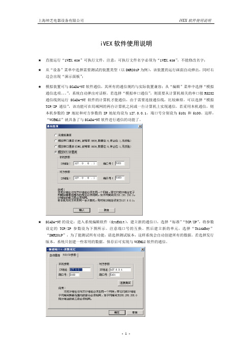
iVEX软件使用说明★直接运行“iVEX.exe”可执行文件,注意:可执行文件名字必须为“iVEX.exe”,不能修改名字;★从“设备”菜单中选择需要测试的装置类型(以DMR201P为例),该装置的运行画面自动弹出,同时右边会出现“演示面板”;★模拟装置可与SCADA-NT软件通信,其所有的通信规约与实际装置兼容;从“编辑”菜单中选择“模拟通信选项。
”,系统自动弹出对话框。
若选择“模拟串口通信”,则需要从计算机相关的串口接RS232通信线到运行SCADA-NT软件的计算机才能通信,由于需要连接通信线,比较麻烦。
可以选择“模拟TCP/IP通信”,该功能可在局域网的两台计算机之间或一台计算机上实现通信。
若采用本机通信,则本机参数的IP地址和对方参数的IP地址均设为127.0.0.1,端口号分别设为5101和5100。
这样,“VCEMLU”就具备了与SCADA-NT软件进行通信的功能了。
★SCADA-NT的设定:进入系统编辑软件(SysEdit),建立新的通信口,选择“标准”“TCP/IP”,将参数设定的TCP/IP参数设为下图所示。
注意端口号的互换。
然后建立新的单元,选择“ThinkBoy”“DMR201P”,为了能测试所有功能,请选择测试版本,这样系统会自动创建所有的数据。
若选择发行版本,系统只创建一些常用的数据。
保存后可实现与VCEMLU软件的通信。
★演示面板的使用:上部是装置的出口继电器KH1~KH6;左边是交流电流电压输入,可设幅值和相位,输入分“正常状态”和“故障状态”两种,并且可以相互切换,以测试保护,正常状态和故障状态的实际输入幅值和相位可分别通过“正常状态设定”和“故障状态设定”进行设置,以模拟不同的故障类型,其中在“故障状态设定”的对话框中可设定故障过渡时间,由正常状态切换到故障状态时,数据会从正常状态等比例连续变化到故障状态,由故障状态切换到正常状态时,数据立即变化到正常状态;右边是所有开关量输入(其中IN01直接从模拟断路器接入),其它的控制输入量包括控制电源失电、合闸回路断线、跳闸回路断线、CT断线、PT断线,以模拟各种告警状态;演示面板内置一个模拟断路器,其中的“○”“┃”分别表示外部控制断路器的分闸和合闸。
TM10e2调试手册

TM-10e2 调试指导本手册的描述下面是TM-10e2逆变器的调试手册—为设备的实际应用而设置适当的参数。
对其操作驱动特定的应用。
在调试过程中,软件TMdrive-Navigator内的参数帮助可获得更多的信息。
(安装程序在文件4GBF0227中处理,当调试装置时有助于减少问题。
)接下来的其他说明,前提都是默认安装是完整和准确的。
本手册的布局重心是在完成第一节步骤过程;如果在调试时出现问题,,那么就必须通过第二节内容来完成项目。
第三节内容只会用在这些情况下。
第一节:初步调试步骤:布线验证→上电启动和装载参数→扭矩调整→电机旋转检查→速度调整→确定传动的应用要求第二节:补充调试附录:电压/赫兹→手动参数调试第三节:支持调试附录:多电机设置→磁化曲线→电可擦只读存储器库→局域网与数字输入设置当需要抓获参数的执行过程时,选择下列程序,并满足他们的使用要求,:Test26、电流调节器性能Test22,速度调节器性能Test29,全过程驱动特性第一部分.详细调试步骤:一.验证连接线:1.检查控制电源电压,及相位顺序控制电源不仅供给风扇,还要以相应电压供给各电路板;1A.使用电压表,确认下面供应控制电源之一:3相 200VAC -- 50Hz;3相 220VAC -- 60Hz;1B.用示波器或相序表,验证提供的控制电源的正确相序U、V、W;2.检查排风扇及风向重要的一点是要确保,从入风口吸入,从柜顶吹出风。
如果相反,可能会导致有很多灰尘进入装置,增加其将来出现问题的可能性。
2A.合风扇开关;2B.分风扇开关;2C.当风扇旋转慢时,检查风扇的转向,确认是从柜顶吹出;如果错误,改变风扇的其中两相电源顺序。
3.验证I / O接线调试时UVS和EXT都需要暂时的短接,另工程师必需在现场,以防出现紧急和需要停止装置的情况。
这两个信号以外的所有其他信号,应该按照每个装置的实际应用,而用线连接。
调试完成后,按UVS和EXT实际应用,用线连接。
IECEx 系统参与与系统费用(第7版)说明书
IECEx OD 019Edition 7.02011-02IECExOPERATIONAL DOCUMENTIEC System for Certification to Standards relating to Equipment for use in Explosive Atmospheres (IECEx System)IECEx System - Participation and System FeesO D 019: 2011 (e )All rights reserved. Unless otherwise specified, no part of this publication may be reproduced or utilized in any form or by any means, electronic or mechanical, including photocopying and microfilm, without permission inAbout the IECThe International Electrotechnical Commission (IEC) is the leading global organization that prepares and publishes International Standards for all electrical, electronic and related technologies.About IEC publicationsThe technical content of IEC publications is kept under constant review by the IEC. Please make sure that you have the latest edition, a corrigenda or an amendment might have been published.▪Catalogue of IEC publications: www.iec.ch/searchpubThe IEC on-line Catalogue enables you to search by a variety of criteria (reference number, text, technical committee). It also gives information on projects, withdrawn and replaced publications.▪IEC Just Published: www.iec.ch/online_news/justpubStay up to date on all new IEC publications. Just Published details twice a month all new publications released. Available on-line and also by email.▪Electropedia: The world's leading online dictionary of electronic and electrical terms containing more than 20 000 terms and definitions in English and French, with equivalent terms in additional languages. Also known as the International Electrotechnical Vocabulary online.▪Customer Service Centre: www.iec.ch/webstore/custservIf you wish to give us your feedback on this publication or need further assistance, please visit the Customer Service Centre FAQ or contact us:Email: **********Tel.: +41 22 919 02 11Fax: +41 22 919 03 00Edition 7.0 2011-02 IECExOPERATIONAL DOCUMENTIEC System for Certification to Standards relating to Equipment for usein Explosive Atmospheres (IECEx System)IECEx Certified Equipment Scheme –IECEx System - Participation and System FeesINTERNATIONALELECTROTECHNICALCOMMISSIONINTERNATIONAL ELECTROTECHNICAL COMMISSION____________IECEx Operational Document 019IECEx Certified Equipment Scheme –IECEx System - Participation and System FeesINTRODUCTIONThis Operational Document, OD 019, sets out the general fees for participation within the IECEx System by Countries and their Ex Certification Bodies and Ex Testing Laboratories. Fees associated with manufacturers or service facilities use of the Schemes are included in as much as they relate to the operation of the Schemes. These costs DO NOT cover the actual testing, assessment and certification costs of the individual Test Laboratory and/or Certification Body. Each ExCB and ExTL is free to impose their own costs in a competitive environment.This Edition has been issued as a result of discussions held during the 2010 ExMC Berlin Meeting and which are recorded in the Confirmed Minutes - ExMC/642B/RM – Confirmed Minutes – 2010 Berlin Meeting of the ExMC and also CAB approval of the 2011 IECEx Budget.Change in this Edition 7 is to include the addition of Clause 4.1.3 IECEx Conformity Mark FeesDocument History:Contact addressIECEx Secretariat Tel: +61 2 8206 6940286 Sussex Street Fax: + 61 2 8206 6272Sydney NSW 2000 E-mail:*********************Australia Web Site: 1. Operational FeesThe “Operational Fees” referred to within this document are those fees that provide an income whereby a fully functional International Certification System for the Ex community can be maintained. The method or means by which IECEx Member Bodies recover the annual fees is a matter determined at the National Level.2. Application Fees for New Countries and ExCBs/ExTLsApplication Fees are applied to Countries and candidate ExCBs and candidate ExTLs seeking to join the IECEx System.2.1 Application Fee for new IECEx Member Bodies (Countries)CHF 4,000 2.2 Application Fee for Certification Bodies from new Countries CHF 3,000 2.3 Application Fees for Testing Laboratories from new Countries CHF 3,000 2.4 Application Fees for Certification Bodies and Testing Laboratories from ExistingMember Countries. Application fees for new Bodies from existing membercountries shall pay the application fee applicable to the year their country joined the IECEx System (as detailed below) or CHF 1’000 whichever is the greater.Thereby giving recognition of investments made by existing IECEx MemberCountries who have been funding the development of the IECEx System overthe past years by way of annual fees and also by way of other contributions, e.g.participation in developmental work of the System.3 Annual FeesAnnual fees apply to countries and their Ex Certification Bodies and Ex Testing Laboratories as a means of contributing to the financing of the System. These are set out in the annual IECEx Budget and posted to the IECEx Website, under ExMC Documents. The formula for calculation of annual fees is set out below:a) Country Contribution (covering 1 ExCB + 1 ExTL for 1 Scheme) CHF 5’250Member Body component (CHF 3’000)ExCB component (CHF 1’250)ExTL Component (CHF 1’000)b) Additional ExCB per Scheme CHF 1’250c) Additional ExTL (applicable to the IECEx 02 Equipment Scheme) CHF 1’000The above annual fees applies to both approved ExCBs / ExTLs and those at the application stage, noting that applicant ExCBs and ExTLs have membership and voting rights of the ExTAG.Item a) applies as a minimum contribution to countries even where there is no ExCB or ExTL.4 IECEx Certificate Fees4.1 IECEx Equipment Certification Scheme (IECEx 02)4.1.1 BackgroundAs a means of securing the long term financing of the IECEx System the IECEx Management Committee, during its 2004 Brdo Meeting, agreed to introduce a “One-Off” Fee for the issuing of an IECEx Equipment Certificate of Conformity. A fee will also apply should any changes be made to an existing IECEx Equipment Certificate of Conformity. This fee is set out as follows: -4.1.2 Certificate Fee LevelThe level set by the IECEx Management Committee is currently set at:•CHF 350 for issuing of new IECEx Equipment Certificates of Conformity•CHF 125 for issuing of IECEx Equipment Certificates of Conformity covering changesNOTE:The CHF 350 for newly issued certificates is a decision from the 2008 Paris ExMC meeting and applies to all new Certificates issued from 1 January 2010 irrespective when the application was made.4.1.3 IECEx Conformity Mark FeesThere are no IECEx fees associated with the issuing of an IECEx Mark License.4.2 IECEx Certified Service Facility Scheme (IECEx 03)4.2.1 BackgroundThe IECEx Management Committee, during its 2007 Denver Meeting, agreed to the introduction of fees for the issuing of an IECEx Certified Service Facility Certificate of Conformity. A fee will also apply should any changes be made to an existing IECEx Certified Service Facility Certificate. These fees are set out as follows>4.2.2 Certificate FeeFees applicable to IECEx Certificates issued under the IECEx Certified Service Facility program (IECEx 03) shall apply as follows:1) Newly Issued Certificates:•Upon Issue of the Certificate (Certificate Fee) CHF 1’000•Annual Fee from 1 January the following and subsequent years subsequent years CHF 500 NOTES:1. The application of an annual fee is due to the likelihood that a Service Facility wouldnormally only hold 1 certificate, given that the 1 certificate may cover all Servicing work undertaken by that Facility.2. The Annual fee applies from the 1st January of the year following the date of acertificate being issued as “Current”.2) Where more than 1 IECEx Service Facility Certificate is held:In situations where a Service Facility holds more than 1 IECEx Certificate, under the IECEx 03 Program, second and subsequent Certificates attract a fee of 50% of the fee shown in 1) above.3) Changes to existing Certificates:•Changes of a Technical Nature, eg scope or location CHF 500•Changes of an Administrative Nature CHF 250 4.3 IECEx Certificate of Personal Competency Scheme (IECEx 05)4.3.1 BackgroundAt the 2008 Sao Paulo meeting the IEC Conformity Assessment Board, CAB approved introduction of the new IECEx Certified Persons Scheme, following the IECEx Management Committee, decisions of its 2008 Paris Meeting. In line with the discussions and decisions of the ExMC Paris 2008 meeting the following Certificate Fees apply as agreed during the 2009 ExMC meeting, to the issuing of IECEx Certificates of Personal Competencies.4.2.2 Certificate Fee per certificate1) Newly Issued Certificates:•Upon Issue of a new Certificate CHF 250• 3 yearly re-newal Fee (re-assessment) CHF 100NOTES:1. Publication of IECEx 05 is under consideration by ExMC.2. There is no annual certificate fee applicable to this Scheme.2) Changes to existing Certificates:•Changes, e.g. scope CHF 1004.4 Collection of Certificate FeeEach IECEx Certification Body (ExCB) is required to collect the Certificate Fee (this may be done by inclusion of the fee in their client’s costs).On no more than a quarterly basis, the IECEx Secretariat will generate an invoice to recover these fees, for the System. Slight variations to this procedure may be made available by the ExCB making arrangements, in advance, with the IECEx Secretary,e.g. a decision may be taken at the national level to have the IECEx Secretariat issue a single invoice to the IECEx Member Body who in turn collects the Certificate Fee from the ExCBs (usually where there is more than one ExCB in a country).5 Surcharges5.1 Surcharges for applications from manufacturers from non-IECEx Member Countries5.1.1 BackgroundSurcharges from manufacturers, applicants or service facilities from non-IECEx Member Countries have been a part of the rules for the IECEx System from the beginning. It is obvious that manufacturers or service facilities from countries that are not Members of the IECEx System may stand to benefit by use of the Scheme’s deliverables in the same manner as manufacturers from IECEx Member countries. A surcharge is seen as a way in which such manufacturers or service facilities provide a contribution towards the operating costs of the System.Surcharges applicable to the IECEx Certified Service Facilities and Certified Persons Schemes relating to applications from Non-member countries currently do not apply and are under future consideration by ExMC.5.1.2 Level of Surcharge for the IECEx Certified Equipment SchemeThe current level of the IECEx surcharge applied to manufacturers from non-IECEx Member Countries is currently set as follows:o CHF 500 per Certificate of Conformity CoC (No ExTR or QAR fee)o CHF 300 per ExTR or QAR (where a CoC is not issued)o Where both ExTR + QAR are issued without a CoC being issued then Surcharge is CHF 3005.1.3 Application of SurchargeThe surcharges in 5.1.2 shall apply to applications where any of the following reside ina non-IECEx member country:1. The applicant2. The manufacturer3. Any manufacturing site5.1.4 Collection of Surcharge FeesAs required by IECEx Operations Manual, OD 009, the ExCB to which the manufacturer has applied, shall inform the manufacturer of the surcharges and shall collect these on behalf of the System and advise the IECEx Secretariat accordingly.The IECEx Secretariat shall arrange for an invoice to be issued to the ExCB, collecting the surcharge fees. The ExCB will then pay the surcharges fees direct to the IECEx Account operated by the IEC Central Office in Geneva.The ExCB has the option to seek individual invoices from the IECEx Secretariat with each application received by the ExCB or, alternatively, may receive a single invoice, following 31 December, to cover all Surcharge Fees received during the year. The ExCB shall inform the IECEx Secretariat of their preferred method of collection.5.2 Surcharges for Late PaymentThe IECEx Management Committee, ExMC, introduced a penalty for late payments with the introduction of a CHF 1,000 surcharge fee. This fee will be added to any outstanding dues.In such situations, the IECEx Secretariat shall issue an invoice to cover this surcharge payment.Where there are any questions concerning the application of the Late Fee Surcharge, e.g. where the Member Body has made efforts to pay the annual fees but the fees have been received shortly after the deadline for payment, the IECEx Secretary in conjunction with the IECEx Chairman and Treasurer shall decide on their application.6 Fees for AssessmentsAssessor fees, payable by the ExCB and ExTL are currently set at:•CHF 1’500 per day or part thereof for Lead Assessors (plus expenses)•CHF 1’250 per day or part thereof for Assessors (plus expenses)As agreed by ExMC, the IECEx Secretariat will issue all invoices to ExCB and ExTL applicants and existing concerning assessments, based on team cost estimates, confirmed by the applicant.The IECEx Secretariat will remunerate the assessors according to the Assessor Internal Remuneration Procedure.7 Fees for Observers attending MeetingsA Fee of CHF 1’000, per delegate, applies for Delegates from Observer countries who have attended beyond 2 meetings._________________。
IEC调试软件IEDScout使用说明
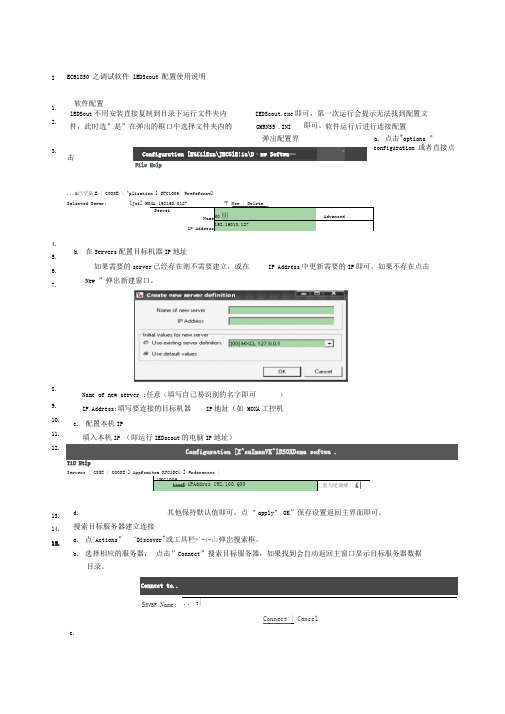
EC61850 之调试软件 lEDScout 配置使用说明软件配置a. 点击"options ”configuration 或者直接点击...&已空砧E | GOOSE \ ^plication ] RFC1006| Prefefencw] Selected Sewer:[Joi] MOXA 192160.0127〒 New | Delete |ServeiNameIP AddressMO 朋 Advanced192.16010.127b. 在Servers 配置目标机器IP 地址如果需要的server 已经存在则不需要建立,或在IP Address 中更新需要的IP 即可,如果不存在点击New ”弹出新建窗口。
Name of new server :任意(填写自己易识别的名字即可 )IP Address:填写要连接的目标机器 IP 地址(如 MOXA 工控机c. 配置本机IP填入本机IP (即运行IEDscout 的电脑IP 地址)Configuration [E^saImanVK^lBSOXDema softwa .TiU HtlpServers | GSSE | GOOSE ] Appfcmito n RFC10C£ ] Prderances |HFC1006Local iPAddrss 192.1G8.Q30匚蓝为逆诵維二i|d.其他保持默认值即可,点 ”apply ” OK ”保存设置返回主界面即可。
搜索目标服务器建立连接a. 点"Actions ” "Discover "或工具栏*'-4-山弹岀搜索框。
b. 选择相应的服务器, 点击”Connect ”搜索目标服务器,如果找到会自动返回主窗口显示目标服务器数据目录。
Connect to.... T | Connect | Cancelc.I1. 2.3.4. 5. 6. 7.8. 9. 10. 11. 12.13. 14. 15.Configuration [E%£ilEzn \JECGlE!ia\D ・nw Softwa —nlEDSout 不用安装直接复制到目录下运行文件夹内 IEDScout.exe 即可,第一次运行会提示无法找到配置文 件,此时选”是”在弹出的框口中选择文件夹内的OMRN55 .INI即可。
IEC61850调试指导手册

IEC61850调试指导手册1、在弹出的对话框中将Ip Address框中输入终端的IP,然后点击“确定”按扭,如下图所示:2、点击“操作”下面的“添加装置连接”,在弹出的对话框中选择刚配置的服务器,然后点击“连接”按钮,如下图所示:3、在出现的页面中点击“建立连接”按钮,再点击“读取模型”按钮,稍等后,将会出现终端的数据模型,展开第一个节点下的“MMTR”下的“ST”,其下的“SupWhSum”、“SupVarhWum”、“DmdWhSum”、“DmdVarhSum”就是第一块电表的四个总电量数据,如下图所示:上行通信的参数设置L30H01-ET304.02_ST01_20150624程序包默认只支持6块电表的数据,相关参数需根据现场实际接入的电表数量进行修改(研发已配置好了支持16块、32块、40块电表的参数,可以直接向研发获取),修改的文件如下:1、wfet3000_hl.icd,该文件需提供给后台系统厂家,由其导入后台系统的SCD文件中,后台系统才能抄读终端数据。
2、model.cfg(终端数据模型参数文件)。
3、meterno2lineno.ini(终端内电表线路号参数文件)。
将修改后的model.cfg,meterno2lineno.ini 通过comtest等升级工具升级到终端,并重启终端。
请注意:1、以上文件的修改能用写字板、记事本工具修改,只能用UltraEdit等支持unix格式的工具修改。
2、model.cfg与meterno2lineno.ini中配置的电表数量必须一样,否则IEC61850程序会运行异常。
与后台系统调试将根据现场修改后的icd文件给后台厂家,后台系统导入icd文件后,可抄读终端数据,后台抄读到的数据与我司wf300软件抄读到的终端数据进行对比,确认后台系统所抄数据正常。
如数据异常,需通过抓包工具(wiresharke)将后台系统与终端的通信报文抓下来分析。
ELUA诊断软件的使用说明

ห้องสมุดไป่ตู้
诊断软件的使用
• 出现的画面
点击这个按 钮会出现右 边画面
以上画面可以看到控制器,驱动器,电机的详细参数(PLC configuration)
END
出现这个画面是正在连接(电脑软件和控制器正在连接)
诊断软件的使用
• 出现的画面
正在连接控制器,并且读取伺服系统的参数
诊断软件的使用
• 出现的画面
点击这个按 钮
可以保存 结果 打开已有 的诊断结 果
诊断软件的使用
• 出现的画面
这边是各个菜单栏,点击后会出现对应的 参数栏
点击show data后显示的控制器的部分参数,左边是各个查看的参数
iVEX使用说明

iVEX软件使用说明★直接运行“iVEX.exe”可执行文件,注意:可执行文件名字必须为“iVEX.exe”,不能修改名字;★从“设备”菜单中选择需要测试的装置类型(以DMR201P为例),该装置的运行画面自动弹出,同时右边会出现“演示面板”;★模拟装置可与SCADA-NT软件通信,其所有的通信规约与实际装置兼容;从“编辑”菜单中选择“模拟通信选项。
”,系统自动弹出对话框。
若选择“模拟串口通信”,则需要从计算机相关的串口接RS232通信线到运行SCADA-NT软件的计算机才能通信,由于需要连接通信线,比较麻烦。
可以选择“模拟TCP/IP通信”,该功能可在局域网的两台计算机之间或一台计算机上实现通信。
若采用本机通信,则本机参数的IP地址和对方参数的IP地址均设为127.0.0.1,端口号分别设为5101和5100。
这样,“VCEMLU”就具备了与SCADA-NT软件进行通信的功能了。
★SCADA-NT的设定:进入系统编辑软件(SysEdit),建立新的通信口,选择“标准”“TCP/IP”,将参数设定的TCP/IP参数设为下图所示。
注意端口号的互换。
然后建立新的单元,选择“ThinkBoy”“DMR201P”,为了能测试所有功能,请选择测试版本,这样系统会自动创建所有的数据。
若选择发行版本,系统只创建一些常用的数据。
保存后可实现与VCEMLU软件的通信。
★演示面板的使用:上部是装置的出口继电器KH1~KH6;左边是交流电流电压输入,可设幅值和相位,输入分“正常状态”和“故障状态”两种,并且可以相互切换,以测试保护,正常状态和故障状态的实际输入幅值和相位可分别通过“正常状态设定”和“故障状态设定”进行设置,以模拟不同的故障类型,其中在“故障状态设定”的对话框中可设定故障过渡时间,由正常状态切换到故障状态时,数据会从正常状态等比例连续变化到故障状态,由故障状态切换到正常状态时,数据立即变化到正常状态;右边是所有开关量输入(其中IN01直接从模拟断路器接入),其它的控制输入量包括控制电源失电、合闸回路断线、跳闸回路断线、CT断线、PT断线,以模拟各种告警状态;演示面板内置一个模拟断路器,其中的“○”“┃”分别表示外部控制断路器的分闸和合闸。
E-Designer 用户手册说明书

E-Designer MA00760 2005-03EnglishPreface E-Designer User’s GuidePrefaceE-Designer is a software application for the configuration of E-series and E1000-series operator terminals. E-Designer helps you create logical, flexible, and effective HMI applications that provide the right information on the right occasion to operators and other systems. This manual is based on an example project that the user completes step by step.E-Designer also includes a Reference Manual (MA00759).© Mitsubishi Electric, MA00760, 2005-02The information in this document is subject to change without notice and is provided as available at the time of printing. The manufacturer reserves the right to change any informa-tion without updating this publication. The manufacturer assumes no responsibility for any errors that may appear in this document. All examples in this document are only intended to improve understanding of the functionality and handling of the equipment. The manufac-turer cannot assume any liability if these examples are used in real applications. In view of the wide range of applications for this software, users must acquire sufficient knowledge themselves in order to ensure that it is correctly used in their specific application. Persons responsible for the application and the equipment must themselves ensure that each applica-tion is in compliance with all relevant requirements, standards and legislation in respect to configuration and safety. The manufacturer will accept no liability for any damage incurred during the installation or use of any equipment mentioned in this document.ContentsContents1Introduction (4)1.1Manual Structure (4)2Installing and Starting the Program (5)2.1System Requirements (5)2.2Installing the Configuration Tool (6)2.3Starting the Configuration Tool (6)3Creating a New Project (7)3.1Select File/New (7)3.2Open the Block Manager (8)3.3Save the Project (8)3.4Add Object (9)4Starting the Simulator (12)5Creating Jumps between Blocks (13)5.1Add a Block (13)5.2Open the Main Block (14)5.3Create a Jump back to the Main Block (14)6Importing Symbols (15)7Adding a Trend Object (17)7.1Test run the Project (18)8Alarm Management (19)8.1Create a Jump back to the Alarm Block (20)8.2Create an Object to Activate the Alarm (20)8.3Test run the Project (21)9Create a Recipe Block (22)9.1Copy Object (24)9.2Create a Series (25)9.3Create Functions to Load and Save Recipes (25)10Report Printouts (27)10.1Print the Report Block (28)11I/O Cross Reference (29)Contents 12I/O Change (30)13Test the Project (31)14Dual Drivers (32)14.1Data Exchange between Controllers (32)15The Terminal as an FTP Server (33)15.1Activate FTP Server (33)Introduction1IntroductionThe E-Designer configuration tool is a software package for the develop-ment of projects for the E-series and E1000-series operator terminals. The HMI system is supplied with all the basic functions you could possibly need for your application. The functions are well tested and have been developed with customer needs and preferences in focus.The configuration tool can be used to easily create a complete process image with the aid of pre-defined objects. In this way, it is easy to gain an overview of a complex application. Users can also customize the pre-defined objects or create their own.Communication drivers for most controllers and automation equipment on the market are available.1.1Manual StructureThis manual is based on examples, which makes it easy to get started with program development with E-Designer. The idea behind the manual is that the reader follows the instructions from the start to finally produce a functioning project that can be further developed or used for ideas. The examples are shown in an operator terminal with touch display.It is assumed that the user has good knowledge of Windows and access to documentation for the Windows 2000/XP operating system. For informa-tion about the use of the configuration tool, refer to the help files (press F1) and the Reference Manual for E1000-series.Installing and Starting the Program 2Installing and Starting the ProgramFor ease of use, we recommend using a mouse with the configuration tool. For keyboard commands, refer to the manual for Windows 2000/XP Professional.The help text for the current function in the program is obtained by pressing the F1 key.2.1System RequirementsHardware and Software RecommendedOperating System Windows 2000 ProfessionalWindows XP ProfessionalProcessor Pentium II, 266 MHzRAM64 MBFree space on hard drive100 MBInstalled software Internet Explorer 5.0 or laterThe configuration tool ought to be used on a color monitor with more than 256 colors.Installing and Starting the Program2.2Installing the Configuration T oolThe configuration tool is supplied on a CD. The manuals can also be read from the CD.The installation creates an icon for the configuration tool in theE-Designer 7 program group.2.3Starting the Configuration T oolOnce the configuration tool is installed, you can start it by selectingE-Designer 7under Start/All Programs/E-Designer 7. The first time the configuration tool is started, the Project Manager is shown together with certain toolbars.Creating a New Project 3Creating a New Project3.1Select File/New...Select File/New... to create a new project. Select Operator Terminal and Controller systems. Click OK. The project is named the first time it is saved.When a new project is created, a tree structure for the project (Project Manager), various menus, toolbars, and object palettes are shown.Creating a New Project3.2Open the Block ManagerIn the manual, we will use the block manager as the starting point when creating our project. Select View/Block Manager to activate the block manager.3.3Save the ProjectSave the project by clicking the diskette symbol or select File/Save as.... Specify a name for the project and the save destination. In this case, name the project User_guide. Finish by clicking Save.Creating a New Project3.4Add Object1.Double-click Main in the block manager. The main block is opened.2.Select the Speedometer object in the object palette and click inthe block. The properties dialog for the object now opens.3.Type D0 in the Analog signal field on the General tab.4.Click OK.The object is now shown in the block. Drag the handles to resize and position the object as desired.Creating a New ProjectWhen, for example, adding objects or drawing graphics in the work area, the Undo function in the Edit menu can be used (10 steps). The keyboard shortcut Ctrl+Z can also be used.5.Now add a slider by selecting theSlider object in the objectpalette and click in the block.6.Type D0 in the Analog signal field on the General tab.7.Click OK .Note:On the Access tab, the Enable operator input function must be checked in order to be able to maneuver the object.Creating a New ProjectStarting the Simulator4Starting the SimulatorThe Simulator is used to test run the project on a personal computer. Savethe project and click the Play button or select Project/Run. Now, a new window is shown, acting as the operator terminal.You can now drag the slider to see how the speedometer changesPress Esc to end the simulator and return to the configuration tool.Creating Jumps between Blocks 5Creating Jumps between Blocks This chapter describes how to create jumps between the different blocks in the project.5.1Add a Block1.Right-click in the block manager and select New Block. Type a namefor the block, in this case Block1, and click OK. The block is now opened.2.Press and hold the left mouse button with the pointer located in themain block in the block manager and drag an arrow to Block1. Ajump is now created to the new block.Block1 is now found in the block manager, as shownCreating Jumps between Blocks5.2Open the Main Block3.Double-click the main block in the block manager.A button has now been automatically created for a jump to Block1.5.3Create a Jump back to the MainBlockCreate a jump back to the main block by dragging an arrow from Block1 to the main block in the block manager. A button is now created in Block1 to implement the jump to the main block.Importing Symbols 6Importing SymbolsIn this chapter we will add a symbol to Block1.1.Double-click on Block1 in the Block Manager.2.Select Symbol in the object palette and click the block. The StaticSymbol dialog opens.3.Click Select. The Select Symbol dialog opens.4.Click Browse....5.Find and select the desired symbol, in this example StaticSymbol2.bmp.Importing SymbolsClick OK.The Digital symbol and Multisymbol objects are added in the same way.Adding a Trend Object 7Adding a Trend ObjectThe trend function is used to store register information from the controller in the operator terminal. We shall now add a trend object with two curves.1.Create a new block and name it Block2.2.Select the T rend object in the object palette and click in the block.The trend dialog now opens.3.Type a name for the trend file, in this example TREND, and select theCurves tab. Make the settings as shown in the figure.Adding a Trend Object4.Click OK.5.Drag to resize and position the object as desired.7.1Test run the ProjectSave the project and click the Play button to test run the project.Alarm Management 8Alarm ManagementWe shall now create a function to generate an alarm.1.Select Functions/Alarms.... The Alarms dialog now opens. Click NewAlarm and make the settings as shown in the figure.2.Type the alarm text Security door open. This text will be shown in thealarm list.3.Specify M0 as the signal to generate the alarm.4.Click OK.5.End Alarms using Exit.Alarm Management8.1Create a Jump to the Alarm Block The alarm block is a so-called system block that already exists. Create a jump to the alarm block by dragging an arrow in the block manager from the main block to the alarm block.8.2Create an Object to Activate theAlarmIn the main block, we add a digital text object that will activate the alarm. Select the object in the object palette and click in the main block. Make the settings in the dialog as shown in the figure.Note:In order to be able to maneuver the object, the Enable operator input function on the Access tab must be checked.Alarm Management 8.3Test run the ProjectSave the project and click the Play button to test run the project.Create a Recipe Block9Create a Recipe BlockThis function is used to save the signal value from the controller in the block in question.1.Add a new block and name it Recipe.2.Add an analog numerical object and make the settings as shown in thefigure.Note:Do not forget to activate Enable operator input on the Access tab.Create a Recipe Block 3.Add a static text object and type D10 as the text in the block.Create a Recipe Block9.1Copy Object4.Select the objects by dragging a frame around them and press Ctrl C.Then press Ctrl V in order to paste a copy. Move the copy so that they are lined up.Edit the new object by double-clicking it. Change the signal to D11 in both the static text and the analog numerical object.Create a Recipe Block9.2Create a Series5.Select the analog numerical objects and select Object/Create Series.6.Specify the number of columns as 6.7.Finish with OK. A series is now created of the relation between thetwo objects first created.You can copy/paste static text objects for the text above the Analog Numer-ic ObjectsCreate a Recipe Block9.3Create Functions to Load and SaveRecipes8.Add a touch key by selecting in the object palette and clicking inthe block.9.The dialog for the key now opens. Select Load recipe under Otherfunctions in the dialog and type the text Load on the T ext tab. 10.Finish by clicking OK.Make another key for Save recipe.During operation, when you select Save a keyboard is shown in order to type the name of the recipe file.11.Finish by clicking OK.Report Printout 10Report PrintoutIn this chapter we will shall create a report printout to be printed on a connected printer.1.Create a new block of the Text type and name it Report.2.Type the desired report text. For example: Report Printout fromE1000-series.3.Add a digital object by selecting a digital text object in the objectpalette and clicking in the block.4.Connect it to the M0 signal.Similarly, add an analog numerical object and connect it to the M1 signal.5.Close the block.Report Printout10.1Print the Report BlockRight-click the report block in the block manager and select Properties. The properties dialog for the block now opens. Specify the M10 signal as Print signal on the Printout tab. When M10 is activated, the report will be printed on the connected printer.I/O Cross Reference 11I/O Cross ReferenceThe I/O Cross Reference function is used to show which signals are used in the project.1.Select View/IO Cross Reference.2.You can specify the start and end signals, for example, D0 to D99. If nointerval is specified, all I/O signals in use are shown.The list that is shown describes the signals with blocks, objects, and pixel positions. No interval is specified for the list below.I/O Change12I/O ChangeIn this chapter we describe how you can easily change a signal throughout the entire project. We shall change D0 to D1.1.Select Edit/I/O Change.2.Type D0 under From I/O and D1 under To I/O.3.Click Start to implement the change.Test the Project 13Test the ProjectWe shall now test the project. Select Project/Test.If you want to test run the project this can be done in the simulator.Dual Drivers14Dual DriversIt is possible to use two different drivers in the operator terminal, which means that the operator terminal can communicate with two different controllers simultaneously.1.Select Project/Properties/Controller2. In the dialog that opens, selectDemo. Finish with OK.2.Create a new block and name it Dual Drivers.3.Make a jump from the main block to Dual Drivers.4.Add an analog numerical object and connect it to C0.5.Add a speedometer and connect it to D0@2 (controller 2)14.1Data Exchange between Controllers1.Select Functions/Data exchange.2.Make the following settings.The Operator Terminal as an FTP 15The Operator Terminal as an FTP ServerFTP (File T ransport Protocol) is a standard Internet protocol. When the operator terminal works as an FTP server it is possible to upload/download files to/from the operator terminal (e.g. recipe files). An FTP client is required in order to upload/download files. HMI Tools, Internet Explorer, Windows Commander, or some other standard FTP program can be used as the FTP client.The FTP server in the operator terminal only allows transfers in passive mode. The operator terminal does not utilize the date stamps on files. The date shown in the FTP client shall therefore be ignored. Language-specific characters are not supported in file names. The files in the different librar-ies in the operator terminal allocate memory from the project memory. Information on the available project memory is included in the file in-fo.txt.15.1Activate FTP Server1.Select Setup/Network/Services.2.Select FTP Server.3.Click Exit.The Operator Terminal as an FTP ServerFig: 1The file structure in the operator terminal.。
Econtrol系统软件使用说明
Econtrols系统软件使用故障保护策略9、ECI EDIS软件安装及使用方法介绍:软件安装:9.1 软件的安装EDIS——Engine Display Interface Software 发动机显示界面软件双击setup.exe安装点击next(下一步),选择安装路径至安装完成。
9.2 软件的使用(确保ECU接线正确、通讯口线束接线正确、连接诊断线)点击开始菜单栏里面的GCP display 图标,出现下图,将密码复制后,点击paste password,再勾上save password and sn ,点击OK进入软件。
主要页面的介绍(主页面、VEcal页面、CLCalNG页面、Boost页面、Service1和Service2、Test页面、Faults页面、)(1)主页面(介绍包含的一些信息:标定文件版本、燃料控制模式等)2、VEcal页面包含有点火提前角、氧浓度、闭环和自适应修正量(3) CLCalNG页面(4) Boost页面(WGP gate pressure 的调整)在怠速状态下调整WGP gage pressure 压力值至23.5左右(6) Test页面(断缸测试、电子油门和节气门的测试)介绍如何断缸测试(spark kill test),以及测试电子油门和节气门(DBW Test)。
注意:现在标定的点火线圈号和气缸号是一致的,也就是1号线圈对应1缸,5号线圈对应5缸,依次类推(测试在以后会有详细介绍)(7) Faults页面(故障)可以看到当前和历史故障,双击历史故障的红点后出现下图可以清除单个历史故障和所有历史故障代码。
还可以根据出现的故障代码判断出现故障的某个环节。
电压值判断传感器是否完好。
9.4 曲线图的采集一、选择参数进行数据采集:1)、用鼠标右键点击所需要采集曲线的参数,这个参数的方框随即会变为绿色2)、最大允许采集10个参数的曲线,选定完成后单击键盘的P键会出现系统绘制出的曲线图。
TM10e2调试手册
TM10e2调试手册TM-10e2调试指导本手册的描述下面是TM-10e2逆变器的调试手册—为设备的实际应用而设置适当的参数。
对其操作驱动特定的应用。
在调试过程中,软件TMdrive-Navigator内的参数帮助可获得更多的信息。
(安装程序在文件4GBF0227中处理,当调试装置时有助于减少问题。
)接下来的其他说明,前提都是默认安装是完整和准确的。
本手册的布局重心是在完成第一节步骤过程;如果在调试时出现问题,,那么就必须通过第二节内容来完成项目。
第三节内容只会用在这些情况下。
第一节:初步调试步骤:布线验证→上电启动和装载参数→扭矩调整→电机旋转检查→速度调整→确定传动的应用要求第二节:补充调试附录:电压/赫兹→手动参数调试第三节:支持调试附录:多电机设置→磁化曲线→电可擦只读存储器库→局域网与数字输入设置当需要抓获参数的执行过程时,选择下列程序,并满足他们的使用要求,:Tet26、电流调节器性能Tet22,速度调节器性能Tet29,全过程驱动特性第一部分.详细调试步骤:一.验证连接线:1.检查控制电源电压,及相位顺序控制电源不仅供给风扇,还要以相应电压供给各电路板;1A.使用电压表,确认下面供应控制电源之一:3相200VAC--50Hz;3相220VAC--60Hz;1B.用示波器或相序表,验证提供的控制电源的正确相序U、V、W;2.检查排风扇及风向重要的一点是要确保,从入风口吸入,从柜顶吹出风。
如果相反,可能会导致有很多灰尘进入装置,增加其将来出现问题的可能性。
2A.合风扇开关;2B.分风扇开关;2C.当风扇旋转慢时,检查风扇的转向,确认是从柜顶吹出;如果错误,改变风扇的其中两相电源顺序。
3.验证I/O接线调试时UVS和E某T都需要暂时的短接,另工程师必需在现场,以防出现紧急和需要停止装置的情况。
这两个信号以外的所有其他信号,应该按照每个装置的实际应用,而用线连接。
调试完成后,按UVS和E某T实际应用,用线连接。
E调试软件IEcout使用说明完整版

E调试软件I E c o u t使用说明HEN system office room 【HEN16H-HENS2AHENS8Q8-HENH1688】IEC61850之调试软件IEDScout配置使用说明1.软件配置2.IEDSout不用安装直接复制到目录下运行文件夹内即可,第一次运行会提示无法找到配置文件,此时选”是”在弹出的框口中选择文件夹内的即可。
软件运行后进行连接配置:3. a.点击“options”?configuration或者直接点击弹出配置界面。
4.5. b.在Servers配置目标机器IP地址6.如果需要的server已经存在则不需要建立,或在IP Address中更新需要的IP即可,如果不存在点击7.“New”弹出新建窗口。
8.9. Name of new server:任意(填写自己易识别的名字即可)10. IP Address: 填写要连接的目标机器IP地址(如MOXA工控机11.c.配置本机IP12.填入本机IP(即运行IEDscout的电脑IP地址)13.14.d.其他保持默认值即可,点”apply”“OK”保存设置返回主界面即可。
15.搜索目标服务器建立连接a.点”Actions”?”Discover”或工具栏弹出搜索框。
b.选择相应的服务器,点击”Connect”搜索目标服务器,如果找到会自动返回主窗口显示目标服务器数据目录。
c.d.e.如果在连接过程中无法找到服务器可以点击“Actions”?”Messages”或查看相当的连接信息排除是否设置不正确16.查看数据17.连接建立后显示的数据目录结果标识如下图:18.19.a. 在连接建立后,主窗口显示目标服务器提供的所有数据目录结构,查看某一节点数的数据请双击该节点弹出20.数据结构窗口查看具体数值。
21.22.b. 数据节点有GGIO,SPC,LLN0,LPHD0等。
23. LLN0,LPHD为设备信息描述数据,描述设备的工作状态,产品类型等。
IEC调试软件IEDScout使用说明
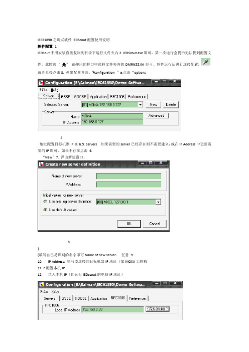
IEC61850之调试软件IEDScout配置使用说明软件配置 1.IEDSout不用安装直接复制到目录下运行文件夹内2.IEDScout.exe即可,第一次运行会提示无法找到配置文件,此时选”是”在弹出的框口中选择文件夹内的OMRN55.INI即可。
软件运行后进行连接配置:或者直接点击3.弹出配置界面。
?configuration ”a.点击“options4.地址配置目标机器IP在b.5.Servers 如果需要的server已经存在则不需要建立,或在IP Address中更新需要的IP即可,如果不存在点击6.“New”7.弹出新建窗口。
8.)(填写自己易识别的名字即可Name of new server:任意9.10.IP Address: 填写要连接的目标机器IP地址(如MOXA工控机11.c.配置本机IP12.填入本机IP(即运行IEDscout的电脑IP地址)13.保存设置返回主界面即可。
“OK”其他保持默认值即可,点14.d.”apply”搜索目标服务器建立连接15.或工具栏弹出搜索框。
Discover”?””Actionsa.点”b.选择相应的服务器,点击”Connect”搜索目标服务器,如果找到会自动返回主窗口显示目标服务器数据目录。
c.d.查看相当的连接信或Messages”?””Actionse.如果在连接过程中无法找到服务器可以点击“息排除是否设置不正确查看数据16.:17.连接建立后显示的数据目录结果标识如下图18.19.a. 在连接建立后,主窗口显示目标服务器提供的所有数据目录结构,查看某一节点数的数据请双击该节点弹出数据结构窗口查看具体数值。
20.21.等。
SPC,LLN0,LPHD022.b. 数据节点有GGIO,23.LLN0,LPHD为设备信息描述数据,描述设备的工作状态,产品类型等。
SPC为具体数据节点,如查电压电流等。
,24.GGIO25.每个数据节点根据功能不同,带不同的功能约束(FC)属性。
优利德 UTS1015E频谱分析仪用户手册 说明书

UTS1015E频谱分析仪用户手册REV12023.10尊敬的用户:您好!感谢您选购全新的优利德仪器,为了正确使用本仪器,请您在本仪器使用之前仔细阅读本使用手册全文,特别有关“安全注意事项”的部分。
如果您已经阅读完本使用手册全文,建议您将此使用手册进行妥善的保管,与仪器一同放置或者放在您随时可以查阅的地方,以便在将来的使用过程中进行查阅。
UNI-T优利德科技(中国)股份有限公司版权所有。
UNI-T产品受中国或其他国家专利权的保护,包括已取得或正在申请的专利。
本公司保留更改产品规格和价格的权利。
UNI-T保留所有权利。
许可软件产品由UNI-T及其子公司或提供商所有,受国家版权法及国际条约规定的保护。
本文中的信息将取代所有以前出版的资料中的信息。
UNI-T是优利德科技(中国)股份有限公司[UNI-TREND TECHNOLOGY(CHINA)CO.,LTD]的注册商标。
如果原购买者自购买该产品之日起一年内,将该产品出售或转让给第三方,则保修期应为自原购买者从UNI-T或授权的UNI-T分销商购买该产品之日起一年内,附件和保险丝等不受此保证的保护。
如果在适用的保修期内证明产品有缺陷,UNI-T可自行决定是修复有缺陷的产品且不收部件和人工费用,或用同等产品(由UNI-T决定)更换有缺陷的产品,UNI-T作保修用途的部件、模块和更换产品可能是全新的,或者经修理具有相当于新产品的性能,所有更换的部件、模块和产品将成为UNI-T的财产。
以下提到的“客户”是指据声明本保证所规定权利的个人或实体。
为获得本保证承诺的服务,“客户”必须在适用的保修期内向UNI-T通报缺陷,并为服务的履行做适当安排,客户应负责将有缺陷的产品装箱并运送到UNI-T指定的维修中心,同时预付运费并提供原购买者的购买证明副本,如果产品要运送到UNI-T维修中心所在国范围内的地点,UNI-T应支付向客户送返产品的费用,如果产品送返到任何其他地点,客户应负责支付所有的运费、关税、税金及任何其他费用。
Tesira EX-IN, EX-AEC, EX-OUT, EX-IO 技术说明书

优点• 输入和输出扩展盒实现了音频信号的远距离接入和发送• 根据系统的变化或对系统进行扩展,扩展设备可以无缝地接入现有的 Tesira 和 TesiraFORTÉ 系统中• 半机架扩展盒安装方便灵活,实现了分布式设计,无需使用设备机柜• 完全通过软件配置和控制功能• AVB 网络实现音频和控制• 由 PoE+供电• 配备欧式凤凰插• 前面板LED ,显示设备状态• 半机架机箱• 获得 CE 标志、UL 认证,符合 RoHS 标准• 享受 Biamp Systems 5 年质保建筑和工程规范4 通道扩展盒应专为 T esira 服务器类设备而设计。
扩展盒应为半机架机箱,由 PoE+ 供电。
扩展盒应能利用 AVB 进行音频联网,并通过软件远程进行配置和控制。
输入、AEC 输入和输入/输出扩展盒应能接收话筒或线路模拟输入,采用欧式凤凰插。
输出和输入/输出扩展盒应能传输线路模拟输出,并采用欧式凤凰插。
A/D 和 D/A 转换应为 24bit 、48kHz 采样率。
扩展盒应具有 CE 标志、UL 认证并与 RoHS 指令兼容。
厂家保修期为5 年。
T esira EX-IN 就是符合以上条件的输入扩展盒。
T esira EX-AEC 就是符合以上条件的 AEC 输入扩展盒.T esira EX-OUT 就是符合以上条件的输出扩展盒。
T esira EX-IO 就是符合以上条件的输入/输出扩展盒。
技术说明书TESIRA® EX-IN,EX-AEC,EX-OUT,EX-IO4 通道输入和输出扩展盒T esira® EX-IN 、EX-AEC 、EX-OUT 和 EX-IO 均为半机架扩展盒,用于 T esira SERVER 、SERVER-IO 和 T esiraFORTÉ AVB 设备。
每个扩展盒共可提供4通道模拟音频。
EX-IN 是 4 通道话筒/线路输入扩展盒,EX-AEC 是带有声学回声消除(AEC )的 4 通道话筒/线路音量输入扩展盒。
- 1、下载文档前请自行甄别文档内容的完整性,平台不提供额外的编辑、内容补充、找答案等附加服务。
- 2、"仅部分预览"的文档,不可在线预览部分如存在完整性等问题,可反馈申请退款(可完整预览的文档不适用该条件!)。
- 3、如文档侵犯您的权益,请联系客服反馈,我们会尽快为您处理(人工客服工作时间:9:00-18:30)。
IEC61850之调试软件IEDScout配置使用说明
1.软件配置
IEDSout不用安装直接复制到目录下运行文件夹内IEDScout.exe即可,第一次运行会提示无法找到配置文件,此时选”是”在弹出的框口中选择文件夹内的OMRN55.INI即可。
软件运行后进行连接配置:
a.点击“options”→configuration或者直接点击弹出配置界面。
b.在Servers配置目标机器IP地址
如果需要的server已经存在则不需要建立,或在IP Address中更新需要的IP即可,如果不存在点击
“New”弹出新建窗口。
Name of new server:任意(填写自己易识别的名字即可)
IP Address: 填写要连接的目标机器IP地址(如MOXA工控机
c.配置本机IP
填入本机IP(即运行IEDscout的电脑IP地址)
d.其他保持默认值即可,点”apply”“OK”保存设置返回主界面即可。
2.搜索目标服务器建立连接
a.点”Actions”→”Discover”或工具栏弹出搜索框。
b.选择相应的服务器,点击”Connect”搜索目标服务器,如果找到会自动返回主窗口显示目标
服务器数据目录。
c.如果在连接过程中无法找到服务器可以点击“Actions” ”Messages”或查看相
当的连接信息排除是否设置不正确
3.查看数据
连接建立后显示的数据目录结果标识如下图:
a. 在连接建立后,主窗口显示目标服务器提供的所有数据目录结构,查看某一节点数的数据请双击该节点弹出
数据结构窗口查看具体数值。
b. 数据节点有GGIO,SPC,LLN0,LPHD0等。
LLN0,LPHD为设备信息描述数据,描述设备的工作状态,产品类型等。
GGIO,SPC为具体数据节点,如查电压电流等。
每个数据节点根据功能不同,带不同的功能约束(FC)属性。
MX:模拟量
ST:状态量
DC:描述
CF:配置
根据不同的FC查看数据,如MX下第一个模拟量f代表当前值(浮点数),q代表质量,t代表数据改变时间。
查看相应的DC下的数据可以知道这个模拟量的描述。
查看CF下的数据可以得知此数据的配置单位等.
c. 查看任一节点数据
在任一节点上点右键弹出菜单:
Read: 单次读,在成功读取后更新该节点下数据
Write: 单次写操作,如果该节点可写,则进行写操作
Start Polling: 定期更新,选择该命令设定相应的ms值后按这个时间周期更新节点下所有数据
Show Attributes: 查看数据的类型
Show Data: 查看数据值
d. 报告方式更新数据
如果数据目录存在RP功能约束节点,表明服务器提供报告更新数据服务,可以根据需要使能相应的报告
功能。
使能相应的报告功能,需在RP节点下的相应报告控制块点击右键弹出控制菜单选择“Enable RCB”
启动报告,选”Disable RCB”停止报告,在使能了报告控制块后选“GI”可以进行一次总召唤报告请求。
在报告成功使能后,RCB中引用的DatSet指向的数据节点数据将按报告周期进行更新,数据节点变成红
底色,并能看到数据更新跳动。
e. 创建数据集
在需要创建数据节点右键弹出菜单选Create DataSet命令弹出创建窗口。
填入相应的数据集名字,并选择相应的数据节点右键”Add To Data Set”加入数据集即可。
添加完数据按”Create”返回主窗口查看Datasets中是否多一个刚才创建的新Dataset。
