HSX使用说明书
HSX Home Server 智能热水控制系统用户手册说明书
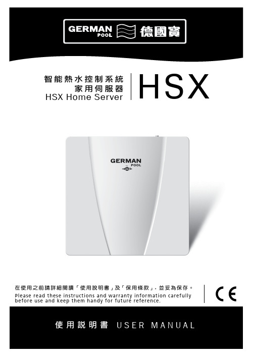
在使用之前請詳細閱讀 「使用說明書」及「保用條款」,並妥為保存。
Please read these instructions and warranty information carefully before use and keep them handy for future reference.HSX Home Server智能熱水控制系統家用伺服器HSX使用說明書U S E R M A N U A L請即進行保用登記﹗有關保用條款細則,請看本說明書最後一頁。
Please register your warranty information now !For Warranty Terms & Conditions,please refer to the last page of these operating instructions.重要提示1.1 如何使用本使用及安裝說明書 1.2 安全指引設備簡介2.1 概覽 2.2 技術規格 2.3 尺寸 2.4 包裝內含物安裝3.1 安裝條件 3.2 安裝位置 3.3 掛牆安裝 3.4 初次使用使用方法4.1 介面及信號燈4.2 家用伺服器與現有網路的連接 4.2.1 通過無線網路連接家用伺服器 4.2.2 通過網路電線連接家用伺服器 4.3 軟件更新 4.3.1 APP更新4.3.2 家用伺服器的軟件更新 4.4 如何使用APP 4.5 恢復出廠設定 4.5.1 重設APP 4.5.2 重設家用伺服器 4.6 清潔與保養疑難排解及客戶服務 5.1 客服地址廢物處理6.1 環境與回收利用目錄03040405060707080811111213121819202013131413171717060917App 圖標環境與回收利用該產品是由高質的元件與材料組成的,均可回收與重複利用。
在產品上的這些標記,代表著這些電子(氣)產品必須和家庭生活垃圾分類處理。
LX-HS05系统基本配置的快速操作方法说明
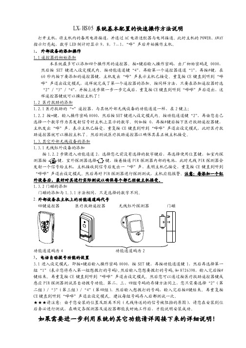
LX-HS05系统基本配置的快速操作方法说明打开主机,将主机内的备用电源接通,并通过AC电源适配器与电网接通。
此时主机的POWER、AWAY 指示灯亮起,数字LED倒计时显示9,8,7…1,“哔”声后开始操作主机。
1.外部设备的添加操作1.1遥控器的初始添加本系统最多可以添加四个操作用的遥控器。
按*键后输入操作密码,出厂初始密码是0000,然后按SET键进入设定模式内。
按功能通道键“4”,再输第一个遥控器通道“1”,再按#键,在60秒内按下要添加的遥控器键,主机发出“哔”声表示主机已接受。
重复按CE键直到听到“哔哔”声退出设定模式,这样就完成了第一个遥控器的添加。
按同样方法,只要在添加遥控器时选“2”/“3”/“4”,并按上述步骤一步一步完成后,重复按CE键直到听到“哔哔”声后退出,这样遥控器键就可以操控主机了!1.2 医疗救助的添加1.2.1医疗救助的“+”遥控器,与其他外部无线设备的功能通道一样,在2键上;1.2.2 按*键,输入操作密码0000,然后按SET键进入设定模式内。
按功能通道键“2”,再由您自己选择一个数字作为其发射信号时主机上显示的数字。
例如按0,再按#键后按下医疗救助遥控器键,主机发出“哔”声,表示主机已接受,重复按CE键直到听到“哔哔”声退出设定模式,此时医疗救助遥控器就可以操控主机了。
然后测试医疗救助遥控器以确保其真正被主机接受。
1.3.其它外部无线设备的添加1.3.1无线红外设备的添加按1.2.2步骤进入功能通道2,选择您之前没有选择的数字键后,再选择使用位置键,如室内探键结束。
再重复按CE键直到听到“哔哔”声退出设定模式。
然后您可以通过按医疗救助遥控器键或感应PIR探测器测试其自动拨号功能。
第二、三、四组号码的存储方法同上,您只需要选择“2”(第二组)/“3”(第三组)/“4”(第四组),然后输入想拨打的号码,输入完后按#键结束。
再重复按CE键直到听到“哔哔”声退出设定模式。
HSS8650 中文操作手册解读

DANI HSS 86.50 顶空进样器中文操作手册DANI HSS 86.50顶空进样器顶空气相色谱法是用来检测低挥发或不挥发溶剂中挥发性物质的方法。
本手册是给DANI HSS 86.50顶空进样器用户提供一个总体上地指导,它包括了安装和使用这台仪器的方针和标准,也包括了HSS 86.50维护和更换部件的信息。
安全信息DANI HSS 86.50是一台IEC(国际电工委员会)安全一级的仪器。
仪器是按照公认的安全标准进行设计并经过测试。
在进行仪器维修之前,必须断开其交流电源。
万一在加热炉里面或者上面碎了一个样品瓶,则仪器在下次使用前必须进行干燥。
安全标志本手册有一些安全标志提醒使用者注意安全操作:WARNING“警告”信息是提醒注意当前的条件或可能出现的情形会伤害用户。
CAUTION“小心”信息是提醒注意当前的条件或可能出现的情形会损坏或毁坏此产品或用户的工作结果。
1.描述DANI HSS 86.50顶空进样器主机(Fig.1)包括:1.1 进样系统1.2 操作程序1.3 气路系统1.1 进样系统进样系统包含三个主要部件(Fig.2/3):1.1.1 样品瓶盘1.1.2 加热炉1.1.3 顶空气体传输部件1.1.1样品瓶盘样品瓶盘有44个位置,位于主机的左边(1-Fig.2)。
通过一个直流马达控制一根分布有单独样品瓶位置的软带,可以向前或向后转动,从而能够带动样品瓶。
1.1.2加热炉加热炉(2-Fig.2)包括一个六位样品瓶转盘,其最大操作温度为200℃,精度1℃。
样品瓶转移系统包含一个装配在横梁(4-Fig.2)上的可移动式抓手(3-Fig.2)。
这个转移系统从样品瓶盘中抓取设定的样品瓶,通过加热炉上的一个进/出口孔(5-Fig.2)把它放进加热炉中。
在加热炉进/出口孔上部有个小盖子(6-Fig.2),打开它就可使用加热炉,这在4.1.6章节会有说明。
在加热时间内,样品瓶可以摇晃。
拿到左侧的面板(7-Fig.2)就能看到仪器内部的电路板。
恒盛兴电力 HSXTX-IX全自动绝缘靴(手套)耐压试验装置 产品说明书

该产品分二部份组成: 1. 绝缘靴(手套)试验车,试验车由:移动托架;盛水水槽;电极杆支撑等组 成; 2. 绝缘靴(手套)操作箱,
绝缘靴(手套)操作箱
4
Anytest 专业测试的首选!
HSXTX-IX 全自动绝缘靴(手套)耐压试验装置使用说明书
高压 变压器
接地端
水槽
高压 水阻
高压 变压器
该产品采用先进的微电子处理技术,全部使用过程可提前进行设置,全中文界 面,操作简单明了。全部测试项目设定后自动进行测试,无须人工干预。
二、工作原理
接入 0~220V 电源,根据电磁感应原理,使变压器产生 0~30KV 工频高压至各 电极,使绝缘靴(手套)获得规定的试验电压。根据绝缘靴(手套)试验规程,读 取、记录测试参数。
九、打印说明
试验完成后按
键进入打印程序,如图:
如上图所示方可进行打印 注意:
1、进行数据打印时,只能对当前测试的结果进行打印。 2、用户在测试前直接进入打印状态进行打印,此时所打印出来的 数据均为零。 打印样式:
试验报告 高压电压: 12.0KV 耐压时间:11
00 S 泄漏电流: I1:0.0mA
我们的宗旨是不断地改进和完善公司的产品,因此您所使用的产品可能与使用说 明书有少许的差别。如果有改动的话,我们会用附页方式告知,敬请谅解!您有不清 楚之处,请与公司售后服务部联络,我们定会满足您的要求。
由于输入输出端子、测试柱等均有可能带电压,您在插拔测试线、电源插座时, 会产生电火花,小心电击,避免触电危险,注意人身安全!
按操作键盘“功能”键进入[过流设定 3]
按操作键盘“功能”键进入[过流设定 4]
9
Anytest 专业测试的首选!
GMN电主轴使用说明书_手动换刀型_cn
continue
GMN 安装使用说明书 103 73 51
主轴 技术
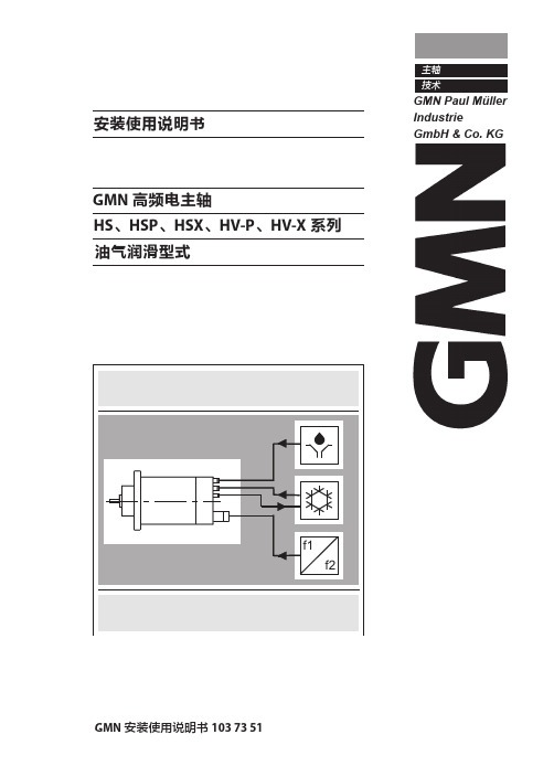
安装使用说明书
GMN 高频电主轴 HS、HSP、HSX、HV-P、HV-X 系列 油气润滑型式
B B
GMN 安装使用说明书 103 73 51
前言
GMN 高频主轴是高精度的精密器械 其性能和使用寿命取决于正确的操作和使用 因此,在使用前所有相关人员(操作者和维护人员)都必须仔细阅读、理解并遵 守本主轴安装使用说明书。
2
GMN 安装使用说明书 103 73 51
SP O3 3.1 3.2 4 4.1 4.2 4.3
基本信息 ................................................................................................................ 5 安全说明................................................................................................................ 7 主轴描述 ................................................................................................................ 9 主轴配备.............................................................................................................................................. 9 主轴运行的供应组件 ...................................................................................................................10 主轴安装 .............................................................................................................. 11 主轴的型号名称 .............................................................................................................................11 主轴的储存和运输 ........................................................................................................................12 主轴夹持............................................................................................................................................13
HS系列说明书

5、统计分析界面
可以统计每天测量工件的数量,及合格率、可修率、超差率;
6、系统设置
该界面一般不需要设置、设置时需要注意操作的正确性,否则会导致仪器无法正常使用;
软件操作手册
HS 系列双面啮合测量仪
操作手册
Manual Veirsion 1.0
HS 系列双面啮合测量仪
软件操作手册
第一章 使用前概述.........................................................................................................................3 一、软件相关符号...................................................................................................................3 二、软件测量项目...................................................................................................................3
实际中心距基础值=心轴 1 直径/2+块规值+心轴 2 直径/2; 输入好中心距基础值之后,将块规放置在两个心轴之间,调整出合适值,选择确定复位 (3)如果设置中心距基础值,先点击“设置基础值”按钮,使基础值编辑框点亮,然后在 编辑框中输入中心距基础值,关闭光栅复位提示,打开参数设置->选择保存参数,中心距基 础值就随着参数一起保存,待下次读取参数时,可直接选择合适的块规进行复位操作。
海斯特FORTENSH6.0FT产品说明书
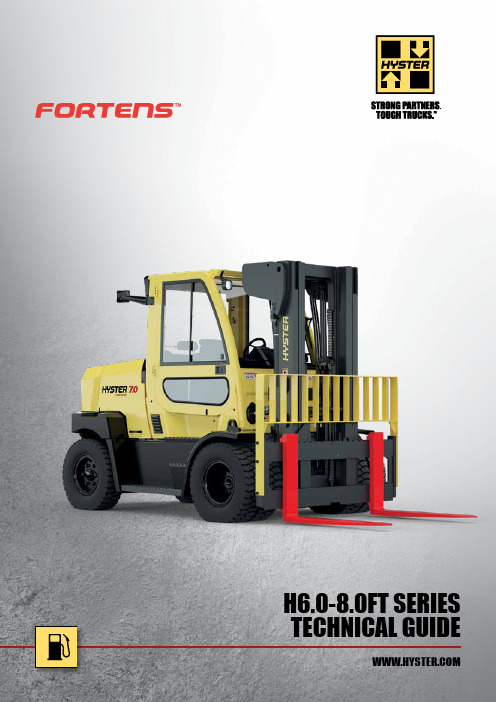
TECHNICAL GUIDEH6.0-8.0FT SERIES2DIMENSIONS h 1sßαh 4h 3h 6m 1h 10yxlc l 1Q1l 5m 2h 7l 2b 2b 1b 11eb 10b 13Wab 5a/2Asta/2H6.0-7.0FTCENTRE OF GRAVITY3h 6h 10h 7y xll 1l 2l 5m 2m 1h 1c Q1sßαh 4h 3b 1b 2b 10b 5eb 13b 11Waa/2Asta/2CENTRE OF GRAVITYH7.0-8.0FTSH6.0FT SPECIFICATIONS 1-11-2H7.0FTS SPECIFICATIONS 1-11-2H8.0FTS SPECIFICATIONS 1-11-27-1Engine manufacturer / modelKUBOTA V3600 62.3KWKUBOTA V3800 81.5KW10-1Operating pressure for attachments bar 155155Parking brakeR A T E D L O A D (k g )STANDARD HOOK TYPE CARRIAGELOAD CENTRE (mm)Load centre - distance from front of forks to centre of gravity of load.Rated load - based on vertical mast.2500350045005500650075008500050010001500H7.0FTH6.0FTH8.0FTSH7.0FTSH7.0FTS9MAST AND CAPACITY INFORMATIONNOTES:Specifications are affected by the condition of the vehicle and how it is equipped, as well as the nature and condition of the operating area. Inform your dealer of the nature and condition of the intended operating area when purchasing your Hyster ® truck.(1) Bottom of forks.(2) W/o load backrest.(3) h 6 subject to +/- 5 mm tolerance. 2549mm for Cab option.(4) Full suspension seat in depressed position. (5) Add 32mm with load backrest.(6) Variable.(7) Measured according to the test cycles and based on the weighting valuescontained in EN12053.All capacities are according to EN1551.MAST TABLES:(1) Deduct 224 with load backrest (2) Add 224 without load backrest (3) Deduct 125 without load backrest (4)Add 125 without load backrestSafety: This truck conforms to the current EU and ANSI requirements.NOTICE:Care must be exercised when handling elevated loads. Operators must be trained and must read, understand and follow the instructions contained in the Operating Manual.All values are nominal values and they are subject to tolerances. For further information, please contact the manufacturer.Hyster products are subject to change without notice.Lift trucks illustrated may feature optional equipment. Values may vary with alternative configurations.Specification data is based on VDI 2198.CERTIFICATION: Hyster lift trucks meet the design and construction requirements of B56.1-1969, per OSHA Section 1910.178(a)(2), and also comply with the B56.1 revision in effect at time of manufacture. Certification of compliance with the applicable ANSI standards appears on the lift truck. Performance specifications are for a truck equipped as described under Standard Equipment on this Technical Guide. Performance specifications are affected by the condition of the vehicle and how it is equipped, as well as by the nature, condition of the operating area, proper service and maintenance of the vehicle. If these specifications are critical, the proposed application should be discussed with your dealer.NOTE: Specifications, unless otherwise listed, are for a standard truck without optional equipment.H6.0FT / H7.0FT / H7.0FTS RATED CAPACITY KG@ 600 MM LOAD CENTREMaximum fork height h 3 + s (mm)Back tilt (°)Lowered height h 1 (mm)Extended height h 4 (mm) (3)Free lift height h 2 + s (m)8.25 x 15-14 Dual pneumatic drive tyresCarriage without sideshift (kg)Carriage with integral sideshift (kg)H8.0FTS H8.0FTS 2-S T A G E L I M I T E D F R E E L I F T 30659°2712435008000796035659°2962485008000795045659°3462585008000793055659°3962685008000790060659°421273500792078103-S T A G E F U L L F R E E L I F T46156°270260771565 (4)8000741055156°300269771865 (4)8000739059656°315274272015 (4)79707360H7.0FTS9 / H8.0FTS RATED CAPACITY KG@ 900 MM LOAD CENTREMaximum fork height h 3 + s (mm)Back tilt (°)Lowered height h 1 (mm)Extended height h 4 (mm) (3)Free lift height h 2 + s (m)8.25 x 15-14 Dual pneumatic drive tyresCarriage without sideshift (kg)Carriage with integral sideshift (kg)H7.0FTS9H8.0FTS H7.0FTS H8.0FTS 2-S T A G E L I M I T E D F R E E L I F T 30659°271243500739067706900632035659°296248500738067606890631045659°346258500736067406880629055659°396268500734067306860628060659°42127350072606650678062003-S T A G E F U L L F R E E L I F T46156°270260771565 (4)688063406430592055156°300269771865 (4)686063206410590059656°315274272015 (4)6840630063905880ERGONOMICS (continued)STD OPT Standard seat belt XHI VIS red seat beltX HI VIS red seat belt with interlock X Air conditioningX Rear drive handle with horn button X Dash mounted 12V auxiliary power outlet XManual lever hydraulic controlsXTouchPoint TMmini lever hydraulic controlsX Joystick X Directional leverXIntegrated directional switch X MonotrolTMX Load weight display XVISIBILITYSTDOPT Dual mirrors side viewX Rear mounted color camera with LCD displayX 2 front and 1 rear LED work lights with stop, tail, indicator & reverse lights X 2 front and 1 rear halogen work lights with stop, tail, indicator & reverse lightsXLED work light protection X Mast mounted LED lights X Hazard warning lights XOPERATIONSTD OPTTurn assist system - H7.0FTS / H7.0FTS9 / H8.0FTS XAudible reverse alarm X Amber strobe lightX Pedestrian awareness light (P .A.L.)X Front pedestrian awareness light (P .A.L.)X Keyswitch start XOperator password startX Push button start with operator password X Push button park brake X Battery disconnect switch X System monitoring package XPremium monitoring packageX Seat switch activated engine, lights and display shutdown system X Signal activated engine shutdown system X Impact monitor with 30s shutdown X Impact monitor with immediate shutdown X Full underbody mesh belly pan X Greasing system for base truck X Optical fuel level sensor X Pressure fuel level sensor X 2 front / 1 rear lifting eyes X Aftermarket-ready telemetry kit X Wireless access card reader X Wireless monitoring - cell XWireless monitoring - wifi X Wireless verification XPACKAGESSTDOPT Cool Truck package which includes belly pan including brake line protection, exhaust wrap, fans in hood key activated and rubber front axle guard XAPPEARANCESTD OPT Hyster yellow paint base truck XSpecial paint colour XSUPPLEMENTAL STDOPT Literature pack X CE certificationX 12 Months / 2,000 Hours manufacturers warranty X36 Months / 6,000 Hours extended warrantyX FEATURES AND OPTIONSSpecial Products Engineering Department (SPED). Contact Hyster for details.www.hyster.eu *********************/HysterEurope @HysterEurope/HysterEuropeSTRONG PARTNERS. TOUGH TRUCKS.TMFOR DEMANDING OPERATIONS, EVERYWHERE.Hyster supplies a complete range of warehouse equipment, IC and electric counterbalanced trucks, container handlers and reach stackers. Hyster is committed to being much more than a lift truck supplier.Our aim is to offer a complete partnership capable ofresponding to the full spectrum of material handling issues: Whether you need professional consultancy on your fleet management, fully qualified service support, or reliable parts supply, you can depend on Hyster.Our network of highly trained dealers provides expert,responsive local support. They can offer cost-effective finance packages and introduce effectively managed maintenance programmes to ensure that you get the best possible value. Our business is dealing with your material handling needs so you can focus on the success of your business today and in the future.HYSTER-YALE UK LIMITED trading as Hyster Europe. Registered Address: Centennial House, Building 4.5, Frimley Business Park, Frimley, Surrey GU16 7SG, United Kingdom.Registered in England and Wales. Company Registration Number: 02636775. ©2020 HYSTER-YALE UK LIMITED, all rights reserved. HYSTER,, STRONG PARTNERS. TOUGH TRUCKS., MONOTROL andare trademarks of HYSTER-YALE Group, Inc.Kubota is a trademark of Kubota Corporation. Grammer is a trademark of Grammer Seating Systems Ltd. Hyster products are subject to change without notice. Forklift trucks illustrated may feature optional equipment.Printed in EU. Part number: 3990331 Rev. 03-01/20HYSTER EUROPECentennial House, Frimley Business Park, Frimley, Surrey, GU16 7SG, England.Tel: +44 (0) 1276 538500。
富士诺彩色扫描声纳CSH-5L CSH-8L操作手册说明书

操作手册彩色扫描声纳CSH-5LCSH-8L型号www.furuno.co.jpPub. No. O ZS-13190-C1 DATE OF ISSUE: Nov. 2010iii目录前言............................................................................................................................v i 系统配置....................................................................................................................v ii 1.操作概述.............................................................................................................1-11.1控制单元......................................................................................................................1-11.2遥控器(选用件)........................................................................................................1-21.3基本操作步骤...............................................................................................................1-31.3.1开启电源............................................................................................................1-31.3.2降下传感器........................................................................................................1-31.3.3发射...................................................................................................................1-41.3.4调整控制单元的背光..........................................................................................1-51.3.5选择显示模式.....................................................................................................1-61.3.6选择显示量程.....................................................................................................1-81.3.7调整增益............................................................................................................1-91.3.8收回传感器和关闭电源......................................................................................1-91.4设置倾斜角................................................................................................................1-101.4.1开启/关闭自动倾斜...........................................................................................1-101.4.2海底和倾斜角...................................................................................................1-121.4.3如何分辨鱼群回波和海底回波..........................................................................1-121.4.4注意事项..........................................................................................................1-131.4.5海面鱼群的倾斜角............................................................................................1-131.4.6适当的倾斜角...................................................................................................1-141.5确定目标的距离和方位...............................................................................................1-141.6“声纳”菜单概述......................................................................................................1-151.6.1操作步骤..........................................................................................................1-151.6.2“声纳”菜单说明............................................................................................1-162.微调声纳画面......................................................................................................2-12.1消除多余回波...............................................................................................................2-12.2清晰显示海面鱼群........................................................................................................2-22.3抑制海底曳尾...............................................................................................................2-22.3.1AGC..................................................................................................................2-22.3.2脉冲长度............................................................................................................2-32.3.3第二AGC.........................................................................................................2-32.4抑制浅水渔场中的海底和海面反射...............................................................................2-42.5抑制声纳干扰和噪讯....................................................................................................2-52.5.1确定噪讯源........................................................................................................2-52.5.2使用干扰抑制功能抑制噪讯...............................................................................2-52.5.3使用噪讯限制功能抑制噪讯...............................................................................2-52.5.4通过TX 周期抑制干扰.....................................................................................2-62.6选择波束宽..................................................................................................................2-72.6.1水平波束宽........................................................................................................2-72.6.2垂直波束宽........................................................................................................2-72.7探测微弱回波...............................................................................................................2-72.8回波平均......................................................................................................................2-7iii3.高级声纳操作......................................................................................................3-13.1跟踪鱼群(目标锁定).................................................................................................3-13.2通过听觉探测鱼群........................................................................................................3-33.3鱼群警报.......................................................................................................................3-43.4测量鱼群速度................................................................................................................3-53.4.1输入鱼群标记.....................................................................................................3-53.4.2删除单个鱼群标记..............................................................................................3-63.5重新定位鱼群以便观察.................................................................................................3-63.6事件标记和本船位置标记..............................................................................................3-73.6.1事件标记.............................................................................................................3-73.6.2输入本船位置标记..............................................................................................3-83.6.3删除事件标记.....................................................................................................3-83.7集体删除标记................................................................................................................3-93.8功能键(F1-F4)...........................................................................................................3-103.8.1操作功能键.......................................................................................................3-103.8.2根据渔场或目标鱼群编程.................................................................................3-103.8.3编程特定功能...................................................................................................3-113.8.4确认功能键程序................................................................................................3-123.9抑制颠簸摇晃造成的影响(减摇装置)......................................................................3-134.回声测深仪模式..................................................................................................4-14.1选择量程.......................................................................................................................4-14.2调节增益.......................................................................................................................4-24.3画面递进速度................................................................................................................4-34.4测量深度.......................................................................................................................4-34.5抑制干扰.......................................................................................................................4-44.6抑制低电平噪讯............................................................................................................4-44.7消除微弱回波................................................................................................................4-54.8“测深仪”菜单上的其它项目......................................................................................4-65.标记和数据.........................................................................................................5-15.1正常显示上的标记和数据..............................................................................................5-15.2回声测深仪和音频显示上的标记和数据........................................................................5-56.屏幕说明.............................................................................................................6-16.1海底回波.......................................................................................................................6-16.2鱼群..............................................................................................................................6-26.3海面反射.......................................................................................................................6-36.4尾迹..............................................................................................................................6-36.5旁波瓣导致的假回波.....................................................................................................6-46.6噪讯和干扰...................................................................................................................6-47.“标记”和“系统”菜单....................................................................................7-17.1“标记”菜单................................................................................................................7-17.2“系统”菜单................................................................................................................7-3 iv8.维护与故障排除..................................................................................................8-18.1一般维护......................................................................................................................8-18.2清洁设备......................................................................................................................8-18.3船体单元维护...............................................................................................................8-28.3.1润滑点,锌板.....................................................................................................8-28.3.2手动升起传感器.................................................................................................8-38.4更换保险丝..................................................................................................................8-48.5更换风扇......................................................................................................................8-48.6故障排除......................................................................................................................8-58.7错误消息......................................................................................................................8-68.8诊断测试......................................................................................................................8-78.8.1选择诊断测试.....................................................................................................8-78.8.2诊断测试说明.....................................................................................................8-8规格......................................................................................................................SP-1 菜单树..................................................................................................................AP-1索引........................................................................................................................IN-1v前言尊敬的 CSH-5L/CSH-8L 用户:承蒙惠购 FURUNO CSH-5L/CSH-8L 彩色扫描声纳。
Dell S2421HS S2721HS S2421HSX S2721HSX 显示器使用指南说明书

Dell S2421HS/S2721HS/S2421HSX/ S2721HSXDell Display Manager使用指南型號:S2421HS/S2721HS/S2421HSX/S2721HSX法規型號:S2421Ht/S2721Ht註:「註」代表可協助您更加善用本產品的重要資訊。
Copyright © 2020 Dell Inc. 或其子公司。
保留所有權利。
Dell、EMC 及其他商標皆為 Dell Inc. 或其子公司所屬商標。
其他商標可能為各擁有者的商標。
2020 – 07修訂版 A00目錄概覽 . . . . . . . . . . . . . . . . . . . . . . . . . . 4使用快速設定對話方塊 . . . . . . . . . . . . . . . . . . 5設定基本顯示器功能 . . . . . . . . . . . . . . . . . . . 7將預設模式指派至應用程式 . . . . . . . . . . . . . . . . 9以 Easy Arrange 配置視窗 . . . . . . . . . . . . . . . .11管理多個視訊輸入 . . . . . . . . . . . . . . . . . . . .15還原應用程式位置 . . . . . . . . . . . . . . . . . . . .17套用節能功能 . . . . . . . . . . . . . . . . . . . . . .18其他快速鍵 . . . . . . . . . . . . . . . . . . . . . . .19將 DDM 附加至使用中視窗(僅限 Window 10) (20)疑難排解 . . . . . . . . . . . . . . . . . . . . . . . .21| 目錄3目錄 | 3概覽Dell Display Manager 為用以管理一台或一組顯示器的 Microsoft Windows 應用程式。
杭州美控自动化技术有限公司双回路数字显示控制仪使用说明书

使用说明书U-HSX 2200-MKCN21.产品介绍双回路数字显示控制仪采用了表面贴装工艺,全自动贴片机生产,具有很强的抗干扰能力。
本仪表支持多种信号类型输入,可与各类传感器、变送器配套使用,实现对温度、压力、液位、速度、力等物理量的测量显示,带报警控制、模拟变送输出、485/232通讯等输出功能,带双屏数码管显示,可自由设定上、下窗口显示内容,可订制数学运算功能,可针对两路测量信号进行加、减、乘、除运算,其适用范围非常广泛。
2.技术参数表1输入输入信号电流电压电阻电偶输入阻抗≤250Ω≥500K Ω输入电流最大限制≤30mA输入电压最大限制≤6V 输出输出信号电流电压继电器24V 配电或馈电输出负载能力≤500Ω≥250K Ω(注:需要更高负载能力时须更换模块)AC220V/0.6(小)DC24V/0.6A (小)AC220V/3A (大)DC24V/3A (大)见备注≤30mA综合参数测量精度0.2%FS ±1字设定方式面板轻触式按键数字设定;参数设定值密码锁定;设定值断电永久保存。
显示方式-1999~9999测量值显示,0~100%测量值光柱显示,发光二级管工作状态显示使用环境环境温度:0~50℃;相对湿度:≤85%RH ;避免强腐蚀气体工作电源AC 100~240V (开关电源),(50-60HZ );DC 20~29V (开关电源)功耗≤5W 结构标准卡入式通讯采用标准MODBUS 通讯协议,RS-485通讯距离可达1公里,RS-232通讯距离可达15米注:仪表带通讯功能时,通讯转换器最好选用有源转换器备注:外形尺寸为D 、E 的仪表继电器输出时允许负载能力为AC220V/0.6A ,DC24V/0.6A 。
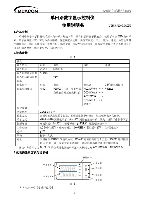
3.仪表的显示面板与功能键图1表2外形尺寸/代码开孔尺寸外形尺寸/代码开孔尺寸160*80mm(横式)/A152*76mm48*96mm(竖式)/E45*92mm80*160mm(竖式)/B76*152mm72*72mm(方式)/F68*68mm96*96mm(方式)/C92*92mm160*80mm(横式光柱)/K152*76mm96*48mm(横式)/D92*45mm80*160mm(竖式光柱)/L76*152mm (2)数码管PV显示窗:显示第一路测量值;可根据要求自行选择显示;在参数设定状态下,显示参数符号。
圣芙玛琪公司紧凑型2产品安装者和用户手册说明书

and Crawlspace DehumidificationP/N 4033600 • Serial No.________________________ Install Date:___________ Sold by:Table of ContentsPrecautions (2)1. Intended Application(s) (2)2. Registrations (2)3. Specifications (3)4. Unit Assembly (3)4.1 Installing Feet (3)4.2 Drain Hose (3)5. Installation (3)5.1 Safety Precautions (3)5.2 Location (3)5.3 Electrical Requirements (3)5.4 Condensate (Water) Removal (3)6. Operation (4)6.1 Humidity Control Adjustment (4)6.2 Defrost Cycle (4)6.3 Fan Operation (4)7. Maintenance (4)7.1 Air Filters (4)7.2 Cleaning Pre-filter (4)7.3 Pleated Filter (5)7.4 Removing Filters (5)7.5 Installing Filters (5)8. Service (5)8.1 Technical Description (5)8.2 Troubleshooting (5)8.3 Refrigerant Charging (6)8.4 Compressor/Capacitor Replacement (6)9. Replacement Parts/Accessories (6)10. Wiring Diagram (6)Warranty (7)Precautions• D o not operate the Santa Fe Compact2 with a cut or frayed power cord.• D o not unplug the unit by pulling on the cord. Grasp the plug firmly and pull it out of the wall socket or power receptacle.• Always use a grounded outlet.• N ever operate electrical equipment near or in standing water.• D o not stick your fingers or other objects through the safety grill.• W hen changing filters, do not stick fingers or other objects in the unit.• D o not restrict airflow in to or out of the unit. This may cause the unit to overheat.• T he unit should never be serviced or cleaned while it is plugged in.• Do not sit or stand on the unit, or use as a shelf or table.• B efore leaving the unit unattended, ensure children do not have access to the equipment. Do not allow children to play with or near the unit or in its air flow.• T he unit is designed to be installed indoors only.• N o user serviceable components. Contact installer or call 1-800-533-7533 for all repair or warranty needs.Read the installation, operation and maintenance instructions carefully before installing and using this unit. Proper adherence to these instructions is essential to obtain maximum benefit from your Santa Fe dehumidifier.1. Intended Application(s)The Santa Fe Compact2 is intended for use in crawlspaces or basements: however, the unit can be placed in almost any residential setting where dehumidification is desired. Use in non-residential applications and pool areas may void warranty.The Santa Fe Compact2 is designed to operate in temperatures between 49° and 95°F. This unit works most effectively between 56° and 95°.In order to efficiently control humidity levels, the area in which the dehumidifier is to be operated must be free of water intrusion or excessive fresh (outside) air infiltration. Before installing the Santa Fe Compact2, water intrusion and air infiltration problems should be addressed.2. RegistrationsThe Santa Fe Compact2 conforms to UL STD 474 and CSA standard C22.2 No. 92.Thank you for purchasing the Santa Fe Compact. For questions regarding this product or to order parts/accessories, contact your dealer or call TOLL-FREE 1-800-533-7533.3. SpecificationsPart Number: 4033600Blower:**********"WGPower:580 watts @ 80°F and 60% RHSupply Voltage:115 volt – 1 phase - 60 HzCurrent Draw: 5.1 AmpsEnergy Factor: 2.4 L/kWhOperating Temp.:49°F Min., 95°F Max.Sized for: Up to 1800 Sq. Ft. - TypicalMinimum Performance at 80°F and 60% RHWater Removal: 70 Pints/DayEfficiency: 5.0 Pints/kWhAir Filter:MERV-8Efficiency: S tandard 65% Efficient, ASHRAE Dust Spot T est Size: 9" x 11" x 1"Power Cord:9', – 110-120 VAC, GroundDrain Connection:3/4" Threaded MPTDrain Hose:5-8" ID x 8'Santa Fe DimensionsUnit ShippingWidth: 12" 15"Height: 12" 17"Length: 21" 25"Weight: 55 lbs 65 lbs4. Unit Assembly4.1 Installing FeetIncluded with your Santa Fe Compact2 are four leveling feet. It is important to level the unit for proper draining. Do not install the feet if you are using the optional hang kit. Adjusting Leveling Feet1. Lay down a protective pad (pillow, blanket, etc.).2. C arefully turn unit onto side.3. Install leveling feet and adjust to the desired position.4. Carefully bring unit to upright position.5. R epeat steps 1-4 until unit is capable of proper drainage as described in section 5.2.3 of this manual.6. Wait a minimum of 10 minutes before operating.Note: Operating the unit immediately after bringing it to an upright position can possibly damage the compressor. A minimum of 10 minutes is needed to allow the compressor oil to return to it’s reservoir for lubrication.4.2 Drain HoseInstall the threaded drain hose fitting into the lower right hand side, on the front of the machine. Place drain hose end on drain port until fully seated. Refer to Section 5.2.3 regarding proper drainage.5. Installation5.1 Safety Precautions• D o not install the Santa Fe Compact2 with the intake or exhaust of the unit within 1' of a wall or other obstruction.• D o not place the unit where curtains or debris can be drawn onto the intake and restrict airflow.• D o not operate in standing water or place the unit near open water.5.2 LocationThe Santa Fe Compact2 can be installed in a variety of locations to meet the dehumidification needs, but should be installed directly in the area to be dehumidified. Other considerations include:1. P roviding access to a 115 VAC power outlet (9' power cord is provided).2. L ocating near a suitable drain (8' drain hose included).3. T he unit is designed to operate while level. If the unit is placed on an unlevel surface, refer to section4.1. Failure to level the unit may result in leakage or improper drainage. 4. T he unit should be hung from the floor joists if there isany possibility of flooding. A flooded unit is not coveredby warranty.5.3 Electrical RequirementsThe Santa Fe Compact2 plugs into a common grounded outlet on a 110-120 VAC 15-Amp circuit. While operating, it draws 5.1 amps @ 80°F, 60% RH and 4.5 amps @ 70°F, 50% RH. Use of a ground fault circuit interrupter (GFCI) protected circuit is recommended. The unit should not be used in areas prone to flooding.5.4 Condensate (Water) RemovalThe Santa Fe Compact2 drains via gravity, therefore, it does not have the ability to push condensate (water) upwards. The drain hose must run down towards the drain location. Condensate can be drained by using the 5/8” clear vinyl hose and the 3/4” threaded adapter provided. Ensure the threaded adapter isthreaded in tightly.The Santa Fe Compact2 requires a drain trap. Creating a drain trap allows a small amount of water to build up in the trap area of the clear hose. This prevents air from back flowing through the hose and into the dehumidifier; essentially causing the unit to backflow water out of the corners of the machine. Position the trap in the hose approximately 8"-10” from the dehumidi-fier and make sure the highest point of the trap is still at least 2”below the black drain port adapter on the dehumidifier. If the highest point of the trap is above the drain port, water will backflow into the dehumidifier. Check the hose regularly to ensure water is draining properly.Several trap options include:For additional information on how to create a proper trap, see our instructional video at:/draintrapUse care to keep the hose as flat to the floor as possible after your trap is in place. Be sure the hose is not kinked or otherwise restricted so water can pass through the hose freely. Improper installation of the drain hose may result in water leakage.If the Santa Fe Compact2 is located too far from the floor drain and the provided hose does not reach, you may use a 1/2” PVC rigid pipe to extend the drain. Rigid PVC tubing is readily available from your local hardware store. Be sure the extension is at a down-word slope to the drain.An optional condensate pump kit may be installed if lift is required to remove condensate. To order, contact your local dealer or visit our website at . You may also reach us by phone at (800) 533-7533.6. Operation6.1 Humidity Control AdjustmentThe humidity control is an adjustable switch that turns the dehumidifier on and off. It turns on when the relative humidity (RH) rises to the dial set point. It turns off when the RH is within ±5% of the set point.Approximate Humidity Levels Per Setting “Drier” 35% to 45% Relative Humidity “Normal” 45% to 55% Relative Humidity(Recommended for most applications)“Humid” 55% to 65% Relative HumidityThe dehumidifier will run continuously until the RH is reduced to the humidity control dial setting. It is notrecommended to set the humidity control to “dry” in rooms under 65°; doing so will result in long periods of ineffective dehumidifier run time.To turn unit on, turn the humidity dial clockwise to therecommended “NORMAL” position and set fan control to “FAN AUTO.” To turn the unit off, turn the humidity dial counter clockwise to the “OFF” position and set fan control to “FANAUTO.”The Humidity Alert ™ (4026208) isavailable to accurately monitor humidity levels. Please contact your dealer or call 1-800-533-7533 to order.6.2 Defrost CycleThis product includes a defrost thermostat. This feature prevents internal damage caused by excessive frost forming within the unit. When the unit is experiencing excessive frost the system will stop dehumidfying and the fan will run until normal operating conditions are present.6.3 Fan OperationTurning the fan switch “FAN ON” will cause the unit’s internal blower to run continuously, whether the unit is dehumidifying or not. This function is desirable if the unit is used for air circulation or filtration. Turning the fan switch to “FAN AUTO” will cause the unit’s internal blower to run only while the unit is dehumidifying.NOTE: Do not operate the unit without the proper filters. The heat exchange coils inside the unit could become clogged, resulting in a loss of effectiveness and/or efficiency and may require disassembly to clean.7.1 Air FiltersThe Santa Fe Compact2 is equipped with a standard MERV-8 65% 1" pleated fabric filter and a 1/4" aluminum framed pre-filter. Operating the unit with a dirty or obstructed filter will reduce dehumidifier capacity and efficiency, and may cause the compressor to cycle on and off unnecessarily.7.2 Cleaning Pre-filterCheck filter every six months. Clean and/or replace when filters are visibly dirty. Replacement filters can be ordered from your dealer or by calling 1-800-533-7533.The 1/4" washable pre-filter should not to be discarded.Inspect for debris, dirt, or other obstructions. Wash the 1/4"PVC materials available from your local hardware store.pre-filter every time the 1" pleated fabric filter is replaced. To clean the 1/4" pre-filter, remove filter from the unit, rinse the 1/4" pre-filter in water with the water flowing through the aluminum support mesh side. Allow the filter to dry completely before reinstalling. Reinstall per section 7.5.7.3 Pleated filterReplace filter every six months per section 7.4-7.5. To orderNOTE: Failure to follow filter handling instructions may result in improper function of the dehumidifier and cause premature filter wear or unit damage.7.4 Removing Filters1. R emove the 1/4" pre-filter by gently pulling on the bottomof the filter frame.2. R emove the 1" pleated fabric filter by gently pulling onthe bottom of the filter frame.7.5 Installing Filters1. A ngle the top of the filter and gently slide 1" pleated filterinto filter slot. Do not force. If resistance is felt, checkalignment for obstructions or debris inside the filterhousing.2. A ngle the top of the filter and gently slide 1/4" pre-filter infront of 1" pleated filter. Do not force. If resistance is felt, check alignment for obstructions or debris inside thefilter housing.Servicing the Santa Fe Compact2, with its high pressure refrigerant system and high voltage circuitry presents a health hazard which could result in death, serious bodily injury, and/or property damage. Only qualified service people should service this unit.8.1 Technical DescriptionThe Santa Fe Compact2 uses a refrigeration system similar to an air conditioner’s to remove heat and moisture from incoming air and add heat to the air that is discharged. Hot, high pressure refrigerant gas is routed from the compressor to the condenser coil. The refrigerant is cooled and condensed by giving up its heat to the air that is discharged from the dehumidifier. The refrigerant liquid then passes through capillary tubing which cause the refrigerant pressure and temperature to drop. It next enters the evaporator coil where it absorbs heat from the incoming air and evaporates. The evaporator operates in a flooded condition, which means that all the evaporator tubes contain liquid refrigerant during normal operation. A flooded evaporator should maintain constant pressure and temperature across the entire coil, from inlet to outlet. The mixture of gas and liquid refrigerant enter the accumulator after leaving the evaporator coil. The accumulator prevents any liquid refrigerant from reaching the compressor. The compressor evacuates the cool refrigerant gas from the accumulator and compresses it to a high pressure and temperature gas to repeat the process.8.2 TroubleshootingFOR THE HOMEOWNER:n If the unit does not work properly, please check the following:— Is the unit unplugged?— Is power to outlet on? (check switch, if applicable)— Is circuit breaker tripped?— Is humidity control set? (turn to “ON”)— Is air flow restricted? (check air filters and grill)If none of the above, call dealer or 1-800-533-7533. FOR THE INSTALLING PROFESSIONAL:n No dehumidification. Neither blower, nor compressor run with fan switch AUTO.1. U nit unplugged or no power to outlet, circuit breakertripped.2. Humidity control set to “Humid” setting.3. L oose connection in internal wiring.4. H umidity control is defective.5. Defective compressor relay.n No dehumidification. Compressor does not run but blower runs with fan switch AUTO and humidity control turned to ON.1. Defrost thermostat open, ambient temperature too low.2. Loose connection in compressor circuit.3. Defective compressor overload.4. Defective compressor or compressor run capacitor.n Blower runs with fan switch AUTO but compressor cycles on & off.1. Low ambient temperature and/or humidity causing unitto cycle through defrost mode.2. Defrost thermostat defective.3. Defective compressor overload.4. Defective compressor.5. Dirty air filter(s) or air flow restriced.n Blower does not run with fan switch in either position.Compressor runs briefly but cycles on and off.1. Loose connection in blower circuit.2. Obstruction prevents impeller rotation.3. Defective blower.4. Defective blower switch.n Evaporator coil frosted continuously, low dehumidifyingcapacity.1. Dirty air filter or air flow restricted.2. D efrost thermostat defective.3. Low refrigerant charge.If none of the above has fixed the issue, call your dealer service department or 1-800-533-7533.8.3 Refrigerant ChargingIf the refrigerant charge is lost due to service or a leak, a new charge must be accurately weighed in. If any of the old charge is left in the system, it must be recovered before weighing in the new charge. Refer to the unit nameplate for the correct charge weight and refrigerant type.8.4 Compressor/Capacitor ReplacementThis compressor is equipped with a two terminal externalCAUTION!must be present to perform some tests. These tests should be performed by a qualified service person.9. Replacement Parts4025560 On/Off Switch 1970010 25A Relay 4027163 15A Relay4029568 Compressor Overload 4021495 Control Knob 4025577 Clear Hose 4026221 Leveling Foot 4029567 Compressor 4027172 Humidity Control 4033032-03 Run Capacitor 4025569 Hose Adaptor 4033031-03 Fan Capacitor 4033358-02 Coil Set 4031384 Impeller4031376Defrost ThermostatAccessories4027168 Pre-Filter 4029748 MERV 8 Filter4030421 MERV 8 Filter 4 Pack + 1 Pre-Filter 4027418 MERV 11 Filter 4 Pack + 1 Pre-Filter 4030113 Pump Kit 4029907 Caster Kit 4029908 Hang Kit4030426 Duct Kit, Supply & Return 4030203 Duct Kit, Supply Only 4030204 Duct Kit, Return Only 4027415 8" Flex Duct 25'4020177 8" Insulated Flex Duct 25'4020175Dehumidistat10. Wiring DiagramTo order, contact your dealer or call 1-800-533-7533.1-800-533-7533. | 。
海洛斯操作手册说明书

HIROSS恒温恒湿机房精密空调操作手册HIMOD系列北京****科技有限公司技术部2009年01月01日目录第一章HIMOD系列海洛斯空调概述....................................................................................1.1型号多 ....................................................................................................................................1.2控制技术先进 ........................................................................................................................1.3制冷系统 ................................................................................................................................1.4送风系统 ................................................................................................................................1.5加湿系统 ................................................................................................................................1.6加热系统 ................................................................................................................................1.7其它 ........................................................................................................................................ 第二章HIMOD系列海洛斯空调型号含义............................................................................ 第三章有关空调的一些资料 ..................................................................................................3.1气流组织方式 ........................................................................................................................3.2盖板纽开启方式 ....................................................................................................................3.3空调重量 ............................................................................................................................3.4机组尺寸及维护空间 ............................................................................................................ 第四章制冷循环管路示意图 ..................................................................................................4.1风冷却(A型).....................................................................................................................4.2水冷却(W型)....................................................................................................................4.3双冷源(D型).....................................................................................................................4.4单系统(C型).....................................................................................................................4.5双系统(C型)..................................................................................................................... 第五章调速风机调速接线示意图........................................................................................... 第六章MICROFACE概述......................................................................................................6.1概述 ........................................................................................................................................6.2Microface面板简介................................................................................................................6.3LCD液晶显示屏介绍 ............................................................................................................ 第七章MICROFACE面板的操作.......................................................................................... 第八章控制器的使用 ..............................................................................................................8.1控制器(HIROMATIC)概述 ..............................................................................................8.2控制器的操作 ........................................................................................................................8.3菜单结构 ................................................................................................................................ 第九章日常维护及特殊维护 ..................................................................................................9.1日常维护 ................................................................................................................................9.2特殊维护 ................................................................................................................................ 第十章常见报警及处理 ................................................................................................................10.1低压报警 ..............................................................................................................................10.2高压报警 ..............................................................................................................................10.3加湿报警 ..............................................................................................................................10.4失风报警 ..............................................................................................................................10.5电加热过热报警 ..................................................................................................................10.6显示器发黑 ..........................................................................................................................10.7空调不制冷 ..........................................................................................................................附录1:参数列表 ....................................................................................................................附录2:报警内容列表 .............................................................................................................附录3:各菜单项含义 .............................................................................................................第一章HIMOD系列海洛斯空调概述HIMOD系列海洛斯空调(HIMOD空调)是当今世界上最先进的机房专用恒温恒湿机房专用精密空调。
xγ射线监测仪使用说明书

xγ射线监测仪使用说明书2012年3月目录1.概述 ----------------------------------------------------------------------- 22.主要技术指标 ----------------------------------------------------------- 22.1 仪器正常使用条件:............................................................................ 22.2 额定工作条件:.................................................................................... 23.仪器功能 ----------------------------------------------------------------- 33.1 声光报警................................................................................................ 33.2 显示单位切换........................................................................................ 33.3 声音报警开关........................................................................................ 33.4 报警阈值设置........................................................................................ 33.5 本机机号设置........................................................................................ 33.6 RS-485通讯功能.................................................................................... 34.操作说明 ----------------------------------------------------------------- 44.1 主面板.................................................................................................... 44.2 显示单位切换功能................................................................................ 54.3 声音报警开关功能................................................................................ 64.4 报警阈值设置........................................................................................ 64.4.1 µGy/h报警阈值设置 ----------------------------------------------------------------------------------- 64.4.2 mR/h报警阈值设置 ------------------------------------------------------------------------------------ 74.4.3 报警阈值增量设置 ------------------------------------------------------------------------------------- 84.5 本机编号设置........................................................................................ 95.操作注意事项 ----------------------------------------------------------- 96.仪器成套 -------------------------------------------------------------- 107.联系方式 ---------------------------------------- 错误!未定义书签。
多功能料理锅HSX一1600说明书

多功能料理锅HSX一1600说明书蒸屉深锅深锅3、深锅手柄4、电源指示灯5、档位指示灯6、档位调节开关7、机身8、机身手柄9、加热盘10、烤盘11、锅盖蒸汽口12、锅盖预热:为了达到最佳烹饪效果,烹饪前可以对机器进行预热。
·产品接通电源前请确保档位调节开关处于“关“的位置。
·始终将本产品置于稳固、水平、平整且隔热的表面上。
将深锅或烤盘放在加热盘上之前,确保加热盘上没有异物或液体。
在预热期间,烤盘会变得非常烫。
用隔热手套握持发烫区域。
·第一次使用本产品时可能会出现一些轻微烟雾。
这是正常现象。
注意:·不要直接在加热盘上烹饪食品。
·深锅和烤盘表面有不粘涂层。
使用木制刮铲搅拌食物。
不要使用金属、尖锐的厨房用具。
·使用深锅进行煮食或者蒸食,请勿超过对应的最大水位线。
·不要将残留食物储存在深锅中。
·使用蒸屉蒸食物时,务必向深锅中加水。
避免深锅干烧。
·用户在使用时如有中途暂停使用的情况,请把档位调节开关移至“关”的位置,再次启动时重新将档位调节开关移动至加热状态。
注意:·每次使用后都应彻底清洁产品。
清洁前请确保已关闭产品并已切断其电源。
清洁前,让深锅、锅盖、烤盘和主机完全冷却。
切勿将产品机身浸入水中或任何其它液体中,深锅和烤盘采用不粘涂层。
不要使用金属厨具或研磨性清洁材料,因为这样可能损坏不粘涂层。
如果食物残渣粘在深锅或烤盘上,请将其浸泡在热水和清洁剂中几分钟。
·使用软布清洁产品外部。
警告-在将产品接通电源以前,首先确认产品底部所标示的电压是作否与当地的电压相符。
火只能将产品用于本用户手册中所述的原定用途。
白如果插头、电源线或产品本身受损,请勿使用本产品。
如果电源线损坏,为避免危险,必须由飞利浦、飞利浦授权的服务中心或类似的专职人员来更换。
产品只能使用带接地线的插座。
不要让电源线接触到高温的表面。
不要将电源线悬挂在放置产品的桌子或工作台的边缘上。
单回路数字显示控制仪使用说明书
增加键:用于增加数值 带打印功能时,用于手动打印
(4)四个指示灯 AL1:第一报警指示灯 AL2:第二报警指示灯 AL3:第三报警指示灯 AL4:第四报警指示灯
4.标准配线
仪表在现场布线注意事项: PV 输入(过程输入) (1)减小电气干扰,低压直流信号和传感器输入的连线应远离强电走线。如果做不到应采用屏蔽导 线,并在一点接地。
96*96mm(方式)/C
92*92mm
160*80mm(横式光柱)/K
152*76mm
96*48mm(横式)/D
92*45mm
80*160mm(竖式光柱)/L
76*152mm
48*96mm(竖式)/E
45*92mm
96*96mm(方式光柱)/M
92*92mm
(2)数码管
PV 显示窗:显示测量值;在参数设定状态下,显示参数符号
为 0.1℃,(1000℃以上自动转为 1℃分辨率)。 时间设定
在仪表 PV 显示测量值的状态下,按压 键进入参数,设定 LOC=130,在 PV 显示 LOC,SV 显示 130 的状态下,按压 键 4 秒,即进入时间参数设定,仪表 PV 显示"dATE",SV 显示当前日期(如:090720 -2009 年 7 月 20 日),在此状态下,可参照仪表参数设定方法,设定当前日期。在仪表当前日期显示状态 下,按压 键,仪表 PV 显示"TlnE",仪表 SV 将显示当前时间(如 183047-18 点 30 分 47 秒),在此状 态下,可参照仪表参数设定方法,设定当前时间。在仪表当前时间显示状态下,再次按压 键,则退出
如果 Loc=577,在 Loc 菜单下,同时按住 键和 键达 4 秒,可以将仪表的所有参数恢复到出厂
卡罗洛加基希电子数字面板表设备介绍说明书

Digital Panel Meters for Industrial Monitoring and ControlIn many automation and process control applications it is important to visually monitor and control variables such as temperature, pressure, vibration etc. A digital panel meter can perform these functions and more - it can provide analog and/or serial re-transmission of the measured value for feedback or data-logging purposes. Carlo Gavazzi offers a complete range of digital panel meters from very basic indicators with no outputs (DI Series) to more complex types (UDM Series), which provide innovative features, such as the multi-color alarm display (also called the "traffic light" function) and the 16-point linearization feature for non-linear input signals. With its modular design, the UDM Series offers great flexibility by providing any input/output combination. The range also includes a cost-effective Universal Signal Conditioner (USC Series), which is a DIN-rail mounted, modular device. By sharing the same input/output modules as the UDM Series, it offers a tremendous number of measuring and control capabilities with a very limited number of modules being required.2The CharacteristicsA wide range of available inputs forvarious applications: voltage, current,frequency, resistance and temperatureModular architecture for medium andhigh-end meters, offering flexiblityand easy configurationDifferent types of outputs available toretransmit the measured variable:analog signal, alarm contacts or serial portEasy to program via keypad or software ports3-, 3 1/2-, 4-digit LED display ordual 6-digit LCD display with alarmand over range indication.3A New Concept of ModularityUSC: 5-slot Module Holder•Maximum In-field Flexibility•Quick Assembly and Configuration•Easy Future ExpansionMeasurement Inputs0.2-2-20mA AC/DC0.2-2-20mA AC/DC + excitation output0.2, 2, 5A AC/DC; 20, 200, 500V AC/DCTC: J-K-S-T-E, Pt100-250-500-1000, Ni100Ω: 0.02, 0.2, 2, 20kΩTachometer: 0.001Hz to 50kHz4To instantly view a data sheet and specify products, visit www.Gavazzi UDM35: 3 1/2-Digit Read-out,or3-Digit + Dummy 0 Read-outDisplay Base UDM40: 4-DigitRead-out, 3-Color DisplayUDM60: Dual 6-DigitRead-out with DualAnalog IndicationPower Supply90 to 260V AC/DC18 to 60V AC/DCOutputsCommunication Port Analog outputs:RS485 and RS232 ports Max 1 analog output:0 to 20mA or 0 to10VDCAlarm outputs:1 relay output2 relay outputs2 relay + 2 open collector outputs4 relay outputs5Specifications are subject to change without notice.USC • Universal signal conditioner • Maximum in-field flexibility • Input signal linearization capability • Programming and network software 6To instantly view a data sheet and specify products, visit www.Gavazzi Online .comDI3 DIN, DI3 72, LDI3, LDM30These value-priced panel meters are easily configurable by dip-switches, this provides a means to set the posi-tion of the decimal point and the primary of the current transformer or to connect a potential transformer.Features/Functions DI3 LDI3 LDM30LDI35/LDM35HUDM40UDM35USC UDM60LDM40UDM60, Two Variables Available at a Glance The 6-digit format provides very accurate mea-surements while the analog indicators show where the variable is compared to its full-scale.UDM40 Color Display RED High priority, abnormal conditionAMBER Low priority, abnormal conditionGREEN Normal condition P r i c eAvailable Modules7Specifications are subject to change without notice.Measurement inputs: LSX, LSE, HSX, TRX, TF1/2RS485 communication port: SXRS232 communication port: SYAnalog output (*): AVRelay and open collector outputs: R1, R2, R4, R5Power supply: H, LUDM35/UDM40/UDM60USCSlot A B C D A B C D E Inputs/Outputs 1 2 3 4 1 2 3 4 5(*) Note: A maximum of one analog output moduleTypeOutput(s) UDM35 UDM40 UDM60 USC Ordering Code UDM35 baseBD35UDM40 baseBD40TachometerCommand inputsUp to 1 alarmUp to 2 alarmsUp to 4 alarmsAnalog output Serial communication Universal power supply DI3 DIN, DI3 72Page 10LDM30, LDI3Page 10LDI35Page 11LDM35HPage 12To instantly view a data sheet and specify products, visit www.Gavazzi 8UDM35 Page 15UDM40Page 16UDM60Page 17USCPage 18LDM40Page 13Specifications are subject to change without notice.9To instantly view a data sheet and specify products, visit www.Gavazzi Online .com 10Hardware FunctionsP e r f o r m a n c e For Performance Icon Definitions see page 19DI3 DIN DI3 72 LDI3 LDM30With just four basic models, this product family is the ideal solution for people with value in mind.DI3 DIN DI3 72 LDI3 LDM30DI3 72, LDI3DI3 DIN LDM30LDM30Description Housing (H x W x D) Type signals Engineering units Accuracy Temperature drift Sampling rate Command inputs Outputs: Alarm Analog Serial Signal/display scaling Power supply Approvals Protection degree 3-DGT µP-based indicator 1A/100VAC, 5A/500VAC1 to 1000HzDC or ACmA, A, V , Hz±(0.5%FS, + 1DGT)±350ppm/°C1 time/secondNot availableNot availableNot availableNot availableYES (CT and VT/PT sel. by dip-switch)24V, 48V, 115V, 230V ACDI 3 72: CE, cCSAus; DI3-DIN: CELDI3: CE, cCSAusLDM30: CE, cURus, cCSAusIP40 (DIN); IP50 (72), IP50(LDI3), IP65 (LDI3 on request; LDM30)Specifications are subject to change without notice.11Hardware Functions Input/OutputP e r f o r m a n c eFor Performance Icon Definitions see page 19LDI353 1/2-DGT µP-based indicator DC and AC Label set DC: ±(0.3%FS + 1DGT) AC: ±(0.5%FS + 1DGT) ±200ppm/°C4 times/second Not available Up to 1 Not available Not available Signal/display scaling. Digitalfilter, Peak and Valley. Burn-out control on temperature input 24, 48, 115, 230VAC, 9 to 32VDC, 40 to 150VDC CE, cCSAus IP65 (on request)DescriptionType signalsEngineering unitsAccuracyTemperature driftSampling rateCommand inputsOutputs: AlarmAnalogSerialOther available characteristicsPower supplyApprovalsProtection degreeLDI35This series is available in two basic models:To instantly view a data sheet and specify products, visit www.Gavazzi Online .com12HardwareFunctions Input/OutputP e r f o r m a n c eFor Performance Icon Definitions see page 19LDM35H3 1/2-DGT µP-based indicator Self adhesive label set DC: ±(0.3%RDG + 3DGT) AC: ±(0.5%RDG + 3DGT) ±150ppm/°C 5 times/second Not available Up to 2 Not available Not available Signal/display scaling. Digitalfilter, Peak and Valley. 90 to 260V AC/DC, 18 to 60V AC/DC CE, cCSAus, cURus IP65DescriptionEngineering unitsAccuracyTemperature driftSampling rateCommand inputsOutputs: AlarmAnalogSerialOther available characteristics Power supplyApprovalsProtection degreeLDM35HSpecifications are subject to change without notice.13Hardware Functions Input/OutputP e r f o r m a n c eFor Performance Icon Definitions see page 19LDM404-DGT µP-based indicator DC: ±(0.1%RDG + 2DGT) AC: ±(0.3%RDG + 2DGT) ±150ppm/°C 5 times/second Not available Up to 2 1 (20mA, 10VDC) RS485 Signal/display scaling. Digitalfilter, Peak and Valley. 90 to 260V AC/DC, 18 to 60V AC/DC CE, cURus and cCSAus pending IP65DescriptionEngineering unitsAccuracyTemperature driftSampling rateCommand inputsOutputs: AlarmAnalogSerialOther available characteristics Power supplyApprovalProtection degreeThe LDM Series has now evolved to a better performing controller with characteristics typically found in higher class products.model tion or analog signal retransmission. If needed it could be LDM40To instantly view a data sheet and specify products, visit www.Gavazzi Online .com14HardwareFunctions Input/OutputP e r f o r m a n c eThe best DPM to suit your needs!For Performance Icon Definitions see page 19UDM35µP-based controller DC and AC TRMSSelf adhesive label set Pulse: ±(0.001%RDG + 3DGT) DC: ±(0.1%RDG + 3DGT) AC: ±(0.3%RDG + 3DGT) ±150ppm/°C 5 times/second 1 (display hold, key pad lock or latch alarm reset) Up to 4 1 (20mA,10VDC) RS485, RS232 Signal/display scaling. Analogoutput scaling. Digital filter, peak and Valley. Burn-out control on temperature inputs only. 90 to 260 AC/DC, 18 to 60V AC/DC CE, cCSAus, cURus IP65Description Type signals Engineering unitsAccuracyTemperature driftSampling rateCommand inputsOutputs: AlarmAnalogSerialOther available characteristicsPower supplyApprovalsProtection degreeUDM35Specifications are subject to change without notice.15HardwareFunctions Input/OutputP e r f o r m a n c eThe best DPM to suit your needs!For Performance Icon Definitions see page 19UDM404-DGT µP-based controller with modular housing Self adhesive label set Pulse: ±(0.001%RDG + 3DGT) DC: ±(0.1%RDG + 3DGT) AC: ±(0.3%RDG + 3DGT) ±150ppm/°C 5 times/second 1 (display hold, key pad lock or latch alarm reset) Up to 4 1 (20mA, 10VDC) RS485, RS232 Signal/display scaling. Analogueoutput scaling. Digital filter. Integra- tion time. Peak and valley. Burn- out control on temp. inputs only. Linearization. Traffic light function. 90 to 260 AC/DC, 18 to 60V AC/DC CE, cCSAus, cURus IP65DescriptionEngineering unitsAccuracyTemperature driftSampling rateCommand inputsOutputs: AlarmAnalogSerialOther available characteristicsPower supplyApprovalsProtection degreeUDM40To instantly view a data sheet and specify products, visit www.Gavazzi Online .com16HardwareFunctions Input/OutputP e r f o r m a n c eUDM606-DGT µP-based controller with DC or AC Self adhesive label set ±(0.001%RDG + 3DGT) ±100ppm/°C 5 times/second 1 (display hold, key pad lock or latch alarm reset) Up to 4 1 (20mA, 10VDC) RS485, RS232 Signal/display scaling. Analogoutput scaling. Digital filter. Peak and valley. Linearization. Combination of the inputs according to predefined functions. Pulse metering and totalizing. 90 to 260 AC/DC, 18 to 60V AC/DC CE, cURus, cCSAus pending IP65DescriptionType signalsEngineering unitsAccuracyTemperature driftSampling rateCommand inputsOutputs: AlarmAnalogSerialOther available characteristicsPower supplyApprovalsProtection degreesuccessful and unique UDM Series now has new complementary model, the UDM 60 - a univeral tachometer counter with dual indication. It is an advanced panel indepen-dent variables, making it two instruments in one. This solu-tion allows the user to maximize panel space, use one me-ter instead of two and save money. The UDM60 features an of an analog display, as the user can see the behaviour of the al-lows the user to see the parameters being measured 'at a BQTFx UDM60The best meter to suit your needs!For Performance Icon Definitions see page 19Specifications are subject to change without notice.17Hardware Functions Input/OutputP e r f o r m a n c e sThe best signal conditioner to suit your needs!For Performance Icon Definitions see page 19USCµP-based signal conditioner with DC and AC TRMS Not available DC: ±(0.1%RDG + 3DGT) AC: ±(0.3%RDG + 3DGT) RPM/Hz: ±(0.001%RDG + 3DGT) ±150ppm/°C 5 times/second 1 (latch alarm reset) Up to 4 1 (20mA, 10VDC) RS485, RS232 Signal/display scaling. Analogoutput scaling. Digital filter. Integration time. Peak and valley. Burn-out control on temp. inputs only. Linearization up to 16 points. 90 to 260 AC/DC, 18 to 60V AC/DC CE, cURus, cCSAus IP20DescriptionType signalsEngineering unitsAccuracyTemperature driftSampling rateCommand inputsOutputs: AlarmAnalogSerialOther available characteristicsPower supplyApprovalsProtection degreeThe LEDs on modules show the power supply USCTo instantly view a data sheet and specify products, visit www.Gavazzi Online .com18Current TransformersTADK TADK2CTD-1XCTD-2XCTD-3XCTD-4XTAD 8TAD 12TACO 110TACO 200Cable and/or bus–bar type AC current transformers; operating frequency: 45 to 65 Hz; max system voltage: 0.72 kV; rated insulation level: 3kV/1min @ 50Hz; security factor: 5; rated secondary current: 5A standard (1A on request); DIN–rail, bus-bar or back-panel mounting. All the products are CE marked.0.50.50.50.5Class 0.515P5150A 2.5 5 cl.3200A 3.256 cl.3250A 2.5 4.52300A 343400A 693500A 1012.54600A 1113.54700A 12.5155750A 1315.55800A 1416.551000A 17.52061200A 2022.561250A 2022.561500A 27.53081600A27.53080.50.50.5/1/5P10Class 0.515P10400A 485500A 6125600A 10205800A 153051000A 204051200A 305051500A 406052000A 508052500A6010050.5/1/5P10Class 0.515P10800A 1530101000A 2040101200A 3060101500A 4080102000A 50100102500A 60120103000A 80160104000A100200100.5/1/5P10Class 0.515P10800A 1530101000A 2040101500A 4080102000A 50100102500A 60120103000A 80160104000A100200100.5/1/5P10Class 0.515P101000A 1530101500A 1530102000A 1530102500A 4080103000A 4080104000A 50100105000A 50100106000A5010010the burden output Primary current at rated output current of 1A/5AAC and DC signal measurement19Easy-to-use Product Selection GuidesUser ManualsDownload BrochuresData Sheetswww.Gavazzi Online .com is an information laden website which offers you the ability to download data sheets, specify products, check pricing and availability, track shipping and so much more:Free Downloadable Programming SoftwareCAD DrawingsAccuracy of the main variables Front housing protection degreeDisplay digits and (sampling rate)Digital filter with action on thedisplay and signal outputsPeak and valley function Instantaneous variables displayingDigital inputs for external command Analog output for variableretransmissionAlarm outputs for variable control Communication port3-color display Excitation output“Traffic light” function. Alarm level connected to the display color Pulse measuring input Integration time LinearizationP E R F O R M A N C E I C O N D E F I N I T I O N SCARLO GAVAZZIA u t o m a t i o n C o m p o n e n t sYour Authorized Distributor:The Complete Product PackageInductive Proximity SensorsTripleshield™ Capacitive Sensors Photoelectric Sensors Inductive Loop Detectors Ultrasonic Sensors Radar Sensors Level Sensors Limit SwitchesMagnetic Switches Solid State RelaysContactors and Overloads Manual Motor Starters Motor ControllersVariable Frequency Drives Electromechanical Relays Pilot Devices Cam SwitchesRotary DisconnectsEnergy Management Digital Panel Meters PID ControllersSwitching Power Supplies Time Delay RelaysCurrent Monitoring Relays Voltage Monitoring Relays Three Phase Monitoring Relays Current Transformers EnclosuresControl Modules Interlock Switches Magnetic Sensors Light Curtains Stack Lights Mat SystemsDupline Field & Installation Bus Building Automation Systems Elevator SystemsA Global Force in Industrial AutomationUSACARLO GAVAZZI INC.750 Hastings LaneBuffalo Grove, IL 60089Tel 847.465.6100Fax 847.465.7373**********************CANADACARLO GAVAZZI (CANADA) INC 2660 Meadowvale Boulevard Mississauga, Ontario L5N 6M6Tel 905.542.0979, Fax 905.542.2248CARLO GAVAZZI (CANADA) LTÉE 3777 Boulevard du Tricentenaire Montréal, Quebec H1B 5W3Tel 514.644.2544, Fax 514.644.2808************************CARLO GAVAZZI has a multitude of sales offi ces spanning North America (not to mention our hundreds of distributors).Therefore, we can be viewed as “your local automation resource” - assisting you every step of the way in fi nding the proper solution for your various application requirements.Naturally, our job is greatly simplifi ed as we have such a vast range of solutions to offer you via our comprehensive product package .Our worldwide sales offi ces make us an ideal business partner, especially for manufacturers of exported machinery , as our products are available locally and they are CE marked.Argentina • Australia • Austria • Bahrain • Belgium • Bolivia • Bosnia • Brazil • Brunei • Bulgaria • CanadaChile • China • Columbia • Croatia • Cyprus • Czech • Denmark • Dominican Republic • Egypt • Estonia Finland • France • Germany • Greece • Hungary • Hong Kong • Iceland • India • Indonesia • Iran • Ireland Italy • JapanJordan • Kenya • Korea • Kuwait • Lebanon • Malaysia • Malta • Maroc • Mauritius • Mexico Netherlands • New Zealand • Norway • Pakistan • Papua New Guinea • Paraguay • Peru • Philippines Poland • Portugal • Qatar • Romania • Russia • Saudi Arabia • Serbia • Singapore • Slovakia • Slovenia South Africa • Spain • Sultanate of Oman • Sweden • Switzerland • Taiwan • Thailand • T unisie • T urkey Ukraine • United Arab Emirates • United Kingdom • Uruguay • United States of America • Venezuela • VietnamB r o c h u r e 3/08Regional / Area Sales Offi ce District Sales Offi ceVisit our website for downloadable data sheets,brochures & pricing: www.Gavazzi Online .comUSA Phone: 847.465.6100 Fax: 800.222.2659Canada Ontario: 905.542.0979 Quebec: 514.644.2544Website Email **********************D P M r o c h u r e 3/08。
华为 XH622 V3 BIOS 软件 V350 版本说明书

XH622 V3V100R003C00SPC613BIOS软件V350版本说明书文档版本01发布日期2016-11-25版权所有© 华为技术有限公司2016。
保留一切权利。
非经本公司书面许可,任何单位和个人不得擅自摘抄、复制本文档内容的部分或全部,并不得以任何形式传播。
商标声明和其他华为商标均为华为技术有限公司的商标。
本文档提及的其他所有商标或注册商标,由各自的所有人拥有。
注意您购买的产品、服务或特性等应受华为公司商业合同和条款的约束,本文档中描述的全部或部分产品、服务或特性可能不在您的购买或使用范围之内。
除非合同另有约定,华为公司对本文档内容不做任何明示或暗示的声明或保证。
由于产品版本升级或其他原因,本文档内容会不定期进行更新。
除非另有约定,本文档仅作为使用指导,本文档中的所有陈述、信息和建议不构成任何明示或暗示的担保。
华为技术有限公司地址:深圳市龙岗区坂田华为总部办公楼邮编:518129网址:or目录1 V350版本说明书 (1)2 V335版本说明书 (2)3 V331版本说明书 (3)4 V327版本说明书 (4)5 V325版本说明书 (5)6 V322版本说明书 (7)7 V318版本说明书 (8)8 V316版本说明书 (9)9 V169版本说明书 (10)10 V157版本说明书 (11)11 V152版本说明书 (12)12 V139版本说明书 (13)13 V132版本说明书 (14)14 V128版本说明书 (15)15 V127版本说明书 (16)16 防病毒扫描说明 (17)1 V350版本说明书发布版本日期:2016-11-25发布许可版本:V350上次更新版本:V335特性描述:●增加128GB 内存支持.●开放IO non-posted prefetch设置菜单.●开放关闭集成显卡功能.●解决配合Haswell CPU,内存性能差问题注意事项:●版本软件与iBMC V228版本配套,升级该软件后需升级配套软件到配套版本。
- 1、下载文档前请自行甄别文档内容的完整性,平台不提供额外的编辑、内容补充、找答案等附加服务。
- 2、"仅部分预览"的文档,不可在线预览部分如存在完整性等问题,可反馈申请退款(可完整预览的文档不适用该条件!)。
- 3、如文档侵犯您的权益,请联系客服反馈,我们会尽快为您处理(人工客服工作时间:9:00-18:30)。
称重传感器技术说明
柯力传感器执行标准:GB/T7551-2008
称重传感器
传感器全国用户产品质
一、综述
模拟传感器工作原理:各系列称重传感器以贴有应变片的弹性体为
敏感原件,在外接激励电源后,输出与外加负荷(力)成正比例的信号
许可证号:浙制00000577号量服务双满意十佳企业,它与相应的仪器配套,可广泛用于料斗秤、配料衡、包装秤等各种电
子衡器和自动称重系统。
此外,还可以选用不同形式的配套仪器,以满
型式批准证号:
产
品
说
明浙换2012F152-33 ISO9001:2008 国际认证企业足计量、检测、调节及控制等其它应用要求。
我公司生产的称重传感器精度高,可靠性好,安装方便,各项性能
稳定,具有良好的防尘防潮等措施,可在各种自然环境下正常工作。
二、传感器额定载荷
10kg、20kg、30kg、40kg、50kg、75kg、100kg、150kg、200kg、2
50kg、300kg、500kg
三、主要技术单项指标
书
(HSX10kg~500kg型)灵敏度
精度等级
输入阻抗
(2.000±0.002)mV/V
C3及以下级别
(400±20)Ω
●
-14使用前仔细阅读本产品使用说明书
●
-14请妥善保管本产品说明书,以备查阅
宁波柯力传感科技股份有限公司输出阻抗
绝缘电阻
(352±3)Ω
≥5000MΩ
便、可靠。
六、电缆芯线色标接线法:求实创新
精益求精追求专业典范创造精确品质
尊敬的用户:
非常感谢您选用本公司的产品
本公司产品适用于:料斗秤、配料衡、包装秤等自动称重系统希望您对我公司产品提出宝贵意见,谢谢。
