奇美液晶屏边板CM 电路图
液晶屏电路原理
D
S
VGS〈Vth
G
D
S
G
(2)Vgs<Vth:訊號保持
D
S
G
D
S
CLC
G
com
1.TFT元件在閘極(G)給予適當電壓。當VGS小於起始電壓 時沒有感應出載子則通道成斷路。
2.故TFT元件可看成開關,當VGS>Vth則ON,當VGS<Vth則 OFF。
8
TFT元件的運作原理
h
G0N,G0P、G1N,G1P、G2N,G2P;B0N,B0P、B1N,B1P、B2N,B2P。时钟数据C CLKP。RSDS按传行模式传送数据,信号触发是双沿的。
三:T-CON T-CON是时序控制器,是逻辑板上的主心片(有逻辑板的屏)。功能是实现将主板/数
上输出的LVDS信号转换成能直接驱动TFT-LCD的源极和门极驱动IC。即是将LVDS信号转 RSDS信号。
8位屏的显示颜色为2 ∧8 ×2 ∧8×2 ∧8=16777216种。
七:灰度电压,COM电压,驱动电压 在逻辑板上DC/DC变换部分产生的,其中灰度电压又叫“伽玛”电压,用于形
COM电压是连接到COM电极上的;驱动电压有门极驱动和源极驱动电压。
液晶屏的基本结构和各部分作用
TFT型液晶屏主要由偏振片,滤色器基板, 液晶,TFT基板,显示电路部分和背光源组 成。在滤色器基板和TFT基板中间冲入液晶, 就构成液晶盒,称为CELL。
2.當ON時信號線的資料寫入液晶電容,此時,TFT元件成 低阻抗(RON),當OFF時TFT元件成高阻抗(ROFF),可防 止信號線資料的洩漏。
3.一般RON與ROFF電阻比至少約為105以上。
11
TFT元件的運作原理
资料:4.3 液晶显示器电路

4.3 单片机与液晶显示电路接口电路设计采用液晶显示可以使显示信息多样化,降低系统的功耗。
本节介绍常用的 MDLS点阵字符型液晶显示模块及LMA97S005AD点阵图形型液晶显示模块接口电路及程序设计。
4.3.1 MDLS点阵字符型液晶显示模块模块及程序设计1. MDLS字符型液晶显示模块与单片机最小系统电路板的接口及操作指令与单片机最小系统电路板的接口J4,如图4.3.1所示。
图4.3.1MDLS字符型液晶显示模块接口从单片机最小系统板原理图中可以得知CS7信号由74LS138译码器产生,当A15A14A13A12=1111时选中CS7,所以CS7的有效地址范围为0XF000H~0XFFFFH,使能信号在读写时由读写信号和片选信号共同产生。
从中可以得出对液晶模块操作地址如表4.3.1所示(没有使用到的地址由0代替):表4.3.1 液晶模块操作地址与控制操作地址CS7 RS R/W 功能0XF000 0 0 0 写指令0XF001 0 0 1 读忙标志和AC值0XF002 0 1 0 写数据0XF003 0 1 1 读数据MDLS系列液晶显示模块的引脚功能定义如表4.3.2所示:表4.3.2 MDLS系列液晶显示模块的引脚功能定义引脚号符号状态功能1 Vss 电源地2 Vdd +5V逻辑3 V0 电源液晶驱动电源4 RS 输入寄存器选择 1:数据; 0:指令5 R/W 输入读写操作选择 1:读;0:写6 E 输入使能信号(MDLS未用,符号NC)7 DB0 三态数据总线8 DB1 三态数据总线9 DB2 三态数据总线10 DB3 三态数据总线11 DB4 三态数据总线12 DB5 三态数据总线13 DB6 三态数据总线14 DB7 三态数据总线(MSB)MDLS字符型液晶显示模块指令集如下所示:(1) 清屏功能:清DDRAM和AC值。
RS R/W DB7 DB6 DB5 DB4 DB3 DB2 DB1 DB00 0 0 0 0 0 0 0 0 1(2) 归位功能:AC=0,光标,画面归HOME位。
奇美2730寸液晶背光灯驱动及保护电路原理分析2

OZ960方框图
驱动板 处理器 存储器 投影镜头
光学
色轮 冷镜 光源
屏幕
OZ960关键脚位描述
2脚OVP(Over Voltage Protection)过压保护 该脚的取样信号是从变压器的输出送来的电压信 号,IC内部设置的极限电平是2V,当取样电压达到这 个极限电平时,IC内部OVP运放输出翻转,保护电路 起动,4个输出激励端停止输出激励脉冲,灯管熄灭, 同时,7脚也没有2.5V的基准电压输出,整个IC不工 作。
U11双电压比较器是用来对输出变压器 T1-T4电流取样信号的电压比较,⑴⑺脚两 个运放输出电平均连接到OZ960的9脚FB输 入,作为对输出变压器T1-T4电流的监测和 保护。
4、LM324(U15)四运算放大器
该IC主要用来对背光控制信号和亮度调 节PWM信号进行电平转换。
5、FDS8958A(U2-U9)双MOSFET
OZ960
输出插座
输出变压器
பைடு நூலகம்
双MOSFET
LM393
LM393
LM324
LM339
一、背光板IC介绍
1、OZ960(U15)背光控制
OZ960是O2Micro公司的一片专用于背 光控制的高效率DC-AC转换IC,具有很宽 的输入电压范围,其亮度控制可用一个模 拟的电压或低频的脉冲宽度调制(PWM) 信号控制。 OZ960采用20脚SSOP封装。
3脚ENA(Enable)点灯使能端 该脚是IC运行与否的使能端,或者说是 灯管点亮的控制端。临界电平设置于1.5V, 当该脚输入电平高于1.5V时,IC开始运行, 灯管点亮,当该脚输入电平低于1.5V时,IC 停止工作,灯管熄灭。 7脚REF(Reference)基准电压 该脚是由5脚电源端经内部稳压后输出的 一个2.5V基准电压,供IC内部和外部电路 工作,IC保护时该脚没有输出。
“奇美”32寸液晶屏逻辑板(TCON)电路分析及故障检修(一、电路原理部分)
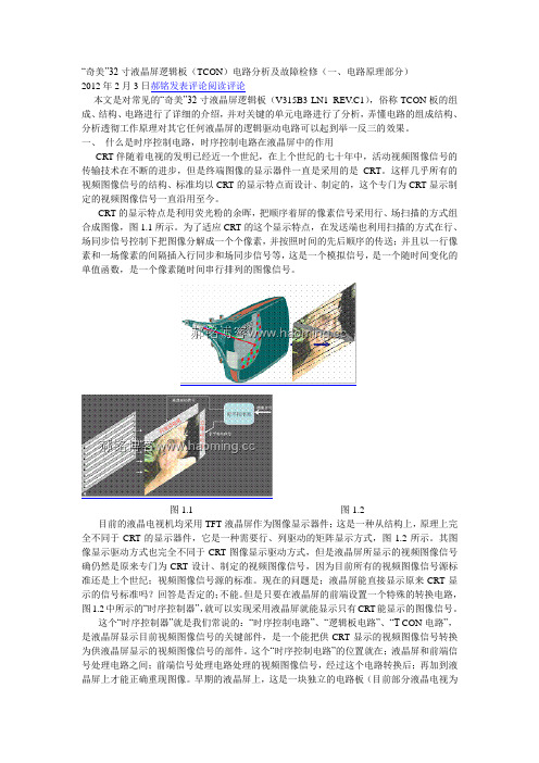
“奇美”32寸液晶屏逻辑板(TCON)电路分析及故障检修(一、电路原理部分)2012年2月3日郝铭发表评论阅读评论本文是对常见的“奇美”32寸液晶屏逻辑板(V315B3-LN1 REV.C1),俗称TCON板的组成、结构、电路进行了详细的介绍,并对关键的单元电路进行了分析,弄懂电路的组成结构、分析透彻工作原理对其它任何液晶屏的逻辑驱动电路可以起到举一反三的效果。
一、什么是时序控制电路,时序控制电路在液晶屏中的作用CRT伴随着电视的发明已经近一个世纪,在上个世纪的七十年中,活动视频图像信号的传输技术在不断的进步,但是终端图像的显示器件一直是采用的是CRT。
这样几乎所有的视频图像信号的结构、标准均以CRT的显示特点而设计、制定的,这个专门为CRT显示制定的视频图像信号一直沿用至今。
CRT的显示特点是利用荧光粉的余晖,把顺序着屏的像素信号采用行、场扫描的方式组合成图像,图1.1所示。
为了适应CRT的这个显示特点,在发送端也利用扫描的方式在行、场同步信号控制下把图像分解成一个个像素,并按照时间的先后顺序的传送;并且以一行像素和一场像素的间隔插入行同步和场同步信号等,这是一个模拟信号,是一个随时间变化的单值函数,是一个像素随时间串行排列的图像信号。
图1.1 图1.2目前的液晶电视机均采用TFT液晶屏作为图像显示器件;这是一种从结构上,原理上完全不同于CRT的显示器件,它是一种需要行、列驱动的矩阵显示方式,图1.2所示。
其图像显示驱动方式也完全不同于CRT图像显示驱动方式,但是液晶屏所显示的视频图像信号确仍然是原来专门为CRT设计、制定的视频图像信号,因为目前所有的视频图像信号源标准还是上个世纪;视频图像信号源的标准。
现在的问题是;液晶屏能直接显示原来CRT显示的信号标准吗?回答是否定的;不能。
但是只要在液晶屏的前端设置一个特殊的转换电路,图1.2中所示的“时序控制器”,就可以实现采用液晶屏就能显示只有CRT能显示的图像信号。
液晶电视cof边板电路诊断解析及维修实例

液晶电视cof边板电路诊断解析及维修实例本文以三星屏、奇美等屏进行分析和介绍,主要讲解边板的作用及组成形式、边板的电路介绍(T-CON板)、如何识别各厂家液晶屏的代表符号、边板上常见问题分析、边板部分的维修思路分析以及维修案例解析等内容。
一、边板的作用及组成形式由主板到屏体之间的信息传递主要包含了T-CON电路、边板和COF后两者是信号的链接线,是OC与PCB链接的纽带,所以要重点研究T-CON电路的原理与维修。
根据厂家屏体设计的不同,主要包含以下几种形式:1、单独的T-CON板电路这是传统的电路组合形式,单独的边条被大多数厂家采用,同时故障率也最高,尤其是LG的边条,只要进水必须要更换便条,严重的还要坏掉COF.原理:由主板产生的LVDS信号送到T-CON板上进行处理转换成需要的各种控制信号(STV、CKV、STH、CKH、POL)及图像数据信号(RSDS)。
以并行的形式加到OC上,呈现图像。
2、边板和T-CON板一体的电路这也是传统的电路组合形式,控制方式同上,只是没有了单独的T-CON板,维修系数增加。
维修时检测几个主要的电压尤为重要:VGH、VGL、VCOM等。
3、高压板、T-CON板和边板一体这款机器少,海尔一款T315XW06 V5的OC使用这种形式。
4、主板直接输出STV、CKV、STH、CKH、POL及图像数据信号(RSDS)到边板,一般都是采用扁排线进边板,现在的一体板很多数采用这种形式,给维修带来了不便。
二、边板的电路介绍(T-CON板)T-CON板,即我们常说的逻辑板,它的结构框图如图1所示,它又被称为中控板、解压板、解码板,是液晶屏显示视频图像信号的关键部件,英语为Timer-Control(时序控制器),缩写为T-CON。
液晶屏驱动电路的供电系统,主要产生四路驱动电路所需的电压, LVDS 信号包括图像的RGB信号和行、场同步信号及时钟、使能信号;这些信号进入时序控制电路后,RGB基色信号经过转换成为RSDS图像数据信号(MINI-LVDS )。
CMI奇美55寸FHD液晶屏手册
□ Tentative Specification■Preliminary Specification□ Approval Specification MODEL NO.: V546HK3SUFFIX: PS5Approved By Checked By Prepared ByChao-Chun Chung Ken WuYI-CHENChiangCONTENTSREVISION HISTORY (4)1. GENERAL DESCRIPTION (5)1.1 OVERVIEW (5)1.2 FEATURES (5)1.3 MECHANICAL SPECIFICATIONS (5)2. ABSOLUTE MAXIMUM RATINGS (6)2.1 ABSOLUTE RATINGS OF ENVIRONMENT (6)2.2 ELECTRICAL ABSOLUTE RATINGS(OPEN CELL) (7)3. ELECTRICAL CHARACTERISTICS (8)3.1 TFT LCD Module (8)4. BLOCK DIAGRAM OF INTERFACE (11)4.1 TFT LCD MODULE (11)5 .INPUT TERMINAL PIN ASSIGNMENT (12)5.1 TFT LCD OPEN CELL (12)5.2 LVDS INTERFACE (20)5.3 COLOR DATA INPUT ASSIGNMENT (21)6. INTERFACE TIMING (24)6.1 INPUT SIGNAL TIMING SPECIFICATIONS (24)6.1.1 Timing spec for Frame Rate = 100Hz (24)6.1.2 Timing spec for Frame Rate = 120Hz (25)6.2 POWER ON/OFF SEQUENCE (Ta = 25 ± 2 ºC) (28)6.2.1 POWER ON/OFF SEQUENCE (28)6.2.2 2D/3D MODE CHANGE2D to 3D SIGNAL SEQUENCE WITHOUT VCC TURN OFF AND TURN ON (29)7. OPTICAL CHARACTERISTICS (30)7.1 TEST CONDITIONS (30)7.2 OPTICAL SPECIFICATIONS (31)8.PRECAUTIONS (34)8.1 ASSEMBLY AND HANDLING PRECAUTIONS (34)8.2 SAFETY PRECAUTIONS (34)9. DEFINITION OF LABELS (35)9.1 OPEN CELL LABEL (35)9.2 CARTON LABEL (37)10. Packaging (38)10.1 PACKING SPECIFICATIONS (38)10.2 PACKING METHOD (38)11. MECHANICAL CHARACTERISTIC (40)Appendix A (42)REVISION HISTORYVersion Date Page(New)Section DescriptionA1(0.0) Oct 03,11 all all Tentative Specification Ver 0.0 was first issued.B1(1.0) Oct 28,11 all all Preliminary Specification Ver 1.0 was first issued.1. GENERAL DESCRIPTION1.1 OVERVIEWV546HK3-PS5 is a 54.6” TFT Liquid Crystal Display product with driver ICs and 4ch-LVDS interface. This product supports 1920 x 1080 HDTV format and can display true 1.073G colors (8-bit + Hi-FRC /color). The backlight unit is not built in.1.2 FEATURESCHARACTERISTICS ITEMS SPECIFICATIONSScreen Diagonal [in] 54.6Pixels [lines] 1920 ×1080Active Area [mm] 1209.6(H) x 680.4(V) (54.6” diagonal)Sub-Pixel Pitch [mm] 0.21(H) x 0.63(V)Pixel Arrangement RGB vertical stripeWeight [g] 3450Physical Size [mm] 1233.2(W) x701.2(H) x 1.80(D) TypDisplay Mode Transmissive mode / Normally blackContrast Ratio 6000:1 Typ.(Typical value measured at CMI’s module)Glass thickness (Array / CF) [mm] 0.7 / 0.7Viewing Angle (CR>20) +88/-88(H),+88/-88(V) Typ.(Typical value measured at CMI’s module)Color Chromaticity R=(0.664, 0.323)G=(0.233, 0.361)B=(0.135, 0.099)W=(0.303, 0.348)* Please refer to “color chromaticity” on 7.2Cell Transparency [%] 6.6%Typ.(Typical value measured at CMI’s module)Polarizer Surface Treatment Anti-Glare coating (3.5% Low Haze)Hardness (H)1.3 MECHANICAL SPECIFICATIONSItem Min. Typ. Max. Unit NoteWeight - 3450 - g -I/F connector mounting position The mounting inclination of the connector makes thescreen center within ±0.5mm as the horizontal. (2)Note (1) Please refer to the attached drawings for more information of front and back outline dimensions. Note (2) Connector mounting position2. ABSOLUTE MAXIMUM RATINGS2.1 ABSOLUTE RATINGS OF ENVIRONMENTValueItemSymbolMin.Max.UnitNoteStorage TemperatureTST-20+60ºC(1)With CMI Module Operating Ambient TemperatureTOP50ºC(1), (2)With CMIModuleNote (1)Temperature and relative humidity range is shown in the figure below. (a) 90 %RH Max. (Ta ≦ 40 ºC).(b) Wet-bulb temperature should be 39 ºC Max. (Ta > 40 ºC).(c) No condensation.Note (2) The maximum operating temperature is based on the test condition that the surface temperature ofdisplay area is less than or equal to 65 ºC with LCD module alone in a temperature controlled chamber. Thermal management should be considered in final product design to prevent the surface temperature of display area from being over 65 ºC. The range of operating temperature may degrade in case of improper thermal management in final product design.2.2 ELECTRICAL ABSOLUTE RATINGS(OPEN CELL)Storage Condition: With shipping package.Storage temperature range: 25±5 ℃Storage humidity range: 50±10%RHShelf life: a month3. ELECTRICAL CHARACTERISTICS3.1 TFT LCD Module(Ta = 25 ± 2 ºC)ValueParameter SymbolMin. Typ. Max.Unit Note Power Supply Voltage V CC10.8 12 13.2 V (1) Rush Current I RUSH--TBD A (2)White Pattern --TBD TBD WHorizontal Stripe --TBD TBD W Power ConsumptionBlack Pattern --TBD TBD WWhite Pattern --TBD TBD AHorizontal Stripe --TBD TBD A Power Supply CurrentBlack Pattern --TBD TBD A(3)Differential Input HighThreshold VoltageV LVTH+100 --mVDifferential Input LowThreshold VoltageV LVTL---100 mVCommon Input Voltage V CM 1.0 1.2 1.4 VDifferential input voltage (single-end) |V ID| 200 -600 mVLVDSinterfaceTerminating Resistor R T-100 -ohm(4)Input High Threshold Voltage V IH 2.7 - 3.3 VCMISinterface Input Low Threshold Voltage VIL0 -0.7 VNote (1) The module should be always operated within the above ranges.Note (2) Measurement condition:Vcc rising time is 470usNote (3) The specified power consumption and power supply current is under the conditions at Vcc = 12 V, Ta =25 ± 2 ºC, f v = 120 Hz, whereas a power dissipation check pattern below is displayed.c. Horizontal PatternNote (4) The LVDS input characteristics are as follows:Active AreaActive Areaa. White Patternb. Black Pattern4. BLOCK DIAGRAM OF INTERFACE 4.1 TFT LCD MODULEGNDVCCL/R_OSCL SDA5 .INPUT TERMINAL PIN ASSIGNMENT5.1 TFT LCD OPEN CELLCNF1 Connector Pin Assignment: (FI-RE51S-HF(JAE) or equivalent)Pin Name Description Note1 N.C. No Connection (1)2 SCL EEPROM Serial Clock (for local dimming demo function)113 SDA EEPROM Serial Data (for local dimming demo function)4 NC No Connection 15 L/R_O Output signal for Left Right Glasses control (10)6 N.C. No Connection (1)7 SELLVDS LVDS Data Format Selection (2)(7)8 N.C. No Connection(1)9 N.C. No Connection10 N.C. No Connection11 GND Ground12 CH1[0]- First pixel Negative LVDS differential data input. Pair 013 CH1[0]+ First pixel Positive LVDS differential data input. Pair 014 CH1[1]- First pixel Negative LVDS differential data input. Pair 1(9)15 CH1[1]+ First pixel Positive LVDS differential data input. Pair 116 CH1[2]- First pixel Negative LVDS differential data input. Pair 217 CH1[2]+ First pixel Positive LVDS differential data input. Pair 218 GND Ground19 CH1CLK- First pixel Negative LVDS differential clock input.(9)20 CH1CLK+ First pixel Positive LVDS differential clock input.21 GND Ground22 CH1[3]- First pixel Negative LVDS differential data input. Pair 323 CH1[3]+ First pixel Positive LVDS differential data input. Pair 3(9)24 CH1[4]- First pixel Negative LVDS differential data input. Pair 425 CH1[4]+ First pixel Positive LVDS differential data input. Pair 426 2D/3D Input signal for 2D/3D Mode Selection (3)(6)(8)27 L/R Input signal for Left Right eye frame synchronous (4)(8)28 CH2[0]- Second pixel Negative LVDS differential data input. Pair 0 (9)29 CH2[0]+ Second pixel Positive LVDS differential data input. Pair 030 CH2[1]- Second pixel Negative LVDS differential data input. Pair 1(9)31 CH2[1]+ Second pixel Positive LVDS differential data input. Pair 132 CH2[2]- Second pixel Negative LVDS differential data input. Pair 233 CH2[2]+ Second pixel Positive LVDS differential data input. Pair 234 GND Ground35 CH2CLK- Second pixel Negative LVDS differential clock input.(9)36 CH2CLK+ Second pixel Positive LVDS differential clock input.37 GND Ground38 CH2[3]- Second pixel Negative LVDS differential data input. Pair 339 CH2[3]+ Second pixel Positive LVDS differential data input. Pair 3(9)40 CH2[4]- Second pixel Negative LVDS differential data input. Pair 441 CH2[4]+ Second pixel Positive LVDS differential data input. Pair 442 LD_EN Input signal for Local Dimming Enable (5)(7)43 SCN_EN Input signal for Scanning Enable (6)(8)44 GND Ground45 GND Ground46 GND Ground47 N.C. No Connection (1)48 VCC +12V power supply49 VCC +12V power supply50 VCC +12V power supply51 VCC +12V power supplyCNF2 Connector Pin Assignment (FI-RE41S-HF (JAE) or equivalent)Pin Name Description Note1 N.C. No Connection2 N.C. No Connection3 N.C. No Connection4 N.C. No Connection(1)5 N.C. No Connection6 N.C. No Connection7 N.C. No Connection8 N.C. No Connection9 GND Ground10 CH3[0]- Third pixel Negative LVDS differential data input. Pair 011 CH3[0]+ Third pixel Positive LVDS differential data input. Pair 012 CH3[1]- Third pixel Negative LVDS differential data input. Pair 1(9)13 CH3[1]+ Third pixel Positive LVDS differential data input. Pair 114 CH3[2]- Third pixel Negative LVDS differential data input. Pair 215 CH3[2]+ Third pixel Positive LVDS differential data input. Pair 216 GND Ground17 CH3CLK- Third pixel Negative LVDS differential clock input.(9)18 CH3CLK+ Third pixel Positive LVDS differential clock input.19 GND Ground20 CH3[3]- Third pixel Negative LVDS differential data input. Pair 321 CH3[3]+ Third pixel Positive LVDS differential data input. Pair 3(9)22 CH3[4]- Third pixel Negative LVDS differential data input. Pair 423 CH3[4]+ Third pixel Positive LVDS differential data input. Pair 424 GND Ground25 GND Ground26 CH4[0]- Fourth pixel Negative LVDS differential data input. Pair 027 CH4[0]+ Fourth pixel Positive LVDS differential data input. Pair 0(9) 28 CH4[1]- Fourth pixel Negative LVDS differential data input. Pair 129 CH4[1]+ Fourth pixel Positive LVDS differential data input. Pair 130 CH4[2]- Fourth pixel Negative LVDS differential data input. Pair 231 CH4[2]+ Fourth pixel Positive LVDS differential data input. Pair 2 (9)32 GND Ground33 CH4CLK- Fourth pixel Negative LVDS differential clock input.(9)34 CH4CLK+ Fourth pixel Positive LVDS differential clock input.35 GND Ground36 CH4[3]- Fourth pixel Negative LVDS differential data input. Pair 337 CH4[3]+ Fourth pixel Positive LVDS differential data input. Pair 3(9)38 CH4[4]- Fourth pixel Negative LVDS differential data input. Pair 439 CH4[4]+ Fourth pixel Positive LVDS differential data input. Pair 440 GND Ground41 GND GroundCN6 Connector Pin Assignment (LM123S-010-H-TF1-3 (UNE) or equivalent)1 N.C. No Connection(1)2 N.C. No Connection3 N.C. No Connection4 GND Ground5 N.C. No Connection (1)6 L/R_O Output signal for Left Right Glasses control (10))7 N.C. No Connection8 N.C. No Connection(1)9 N.C. No Connection10 N.C. No ConnectionNote (1) Reserved for internal use. Please leave it open.Note (2) LVDS format selection.L= Connect to GND, H=Connect to +3.3V or openSELLVDS NoteL JEIDA FormatH or Open VESA FormatNote (3) 2D/3D mode selection.L= Connect to GN D or Open, H=Connect to +3.3V2D/3D NoteL or Open2D Mode H3D ModeNote (4) Input signal for Left Right eye frame synchronousV IL =0~0.8 V, V IH =2.0~3.3 VL/R NoteL Right synchronous signal HLeft synchronous signalNote (5) Local dimming enable selection.L= Connect to GN D H=Connect to +3.3V or OpenLD_EN NoteL or Open Local Dimming Disable H or OpenLocal Dimming EnableNote (6) Scanning enable selection.L= Connect to GN D or Open, H=Connect to +3.3V SCN_EN NoteL or OpenScanning Disable HScanning EnableNote (7) SELLVDS 、LD_EN signal pin connected to the LCM side has the following diagram.R1 in the system side should be less than 1K Ohm. (R1 < 1K Ohm)Note (8) 2D/3D, L/R and SCN_EN signal pin connected to the LCM side has the following diagram.System side R1 < 1KLCM side System sideR1 in the system side should be less than 1K Ohm. (R1 < 1K Ohm)Note (9) LVDS 4-port Data MappingPort Channel of LVDS Data Stream1st Port First Pixel 1, 5, 9, ……1913, 19172nd Port Second Pixel 2, 6, 10, ….1914, 19183rd Port Third Pixel 3, 7, 11, ….1915, 19194th Port Fourth Pixel 4, 8, 12, ….1916, 1920Note (10) The definition of L/R_O signal as followsL= 0V , H= +3.3VL/R_O NoteL Right glass turn onH Left glass turn onNote (11) Please reference Appendix A.Note (12) The screw hole which is distant from the connector is merged with Ground5.2 BLOCK DIAGRAM OF INTERFACEAR0~AR9: First pixel R dataAG0~AG9: First pixel G dataAB0~AB9: First pixel B dataBR0~BR9: Second pixel R dataBG0~BG9: Second pixel G dataBB0~BB9: Second pixel B dataDE: Data enable signalDCLK: Data clock signalThe third and fourth pixel are followed the same rules.CR0~CR9: Third pixel R dataCG0~CG9: Third pixel G dataCB0~CB9: Third pixel B dataDR0~DR9: Fourth pixel R dataDG0~DG9: Fourth pixel G dataDB0~DB9: Fourth pixel B dataNote (1) A ~ D channel are first, second, third and fourth pixel respectively.Note (2) The system must have the transmitter to drive the module.Note (3) LVDS cable impedance shall be 50 ohms per signal line or about 100 ohms per twist-pair line when it is used differentially.5.2 LVDS INTERFACEJEIDA Format : SELLVDS = LVESA Format : SELLVDS = H or OpenAR0~AR9: First Pixel R Data (9; MSB, 0; LSB)AG0~AG9: First Pixel G Data (9; MSB, 0; LSB)AB0~AB9: First Pixel B Data (9; MSB, 0; LSB)DE : Data enable signalDCLK : Data clock signalRSV: Reserved5.3 COLOR DATA INPUT ASSIGNMENTThe brightness of each primary color (red, green and blue) is based on the 10-bit gray scale data input for the color. The higher the binary input, the brighter the color. The table below provides the assignment of the color versus data input.Data SignalRed Green BlueColorR9 R8 R7 R6 R5 R4 R3 R2 R1 R0 G9 G8 G7 G6 G5 G4 G3 G2 G1 G0 B9 B8 B7 B6 B5 B4 B3 B2 B1 B0Basic Colors BlackRedGreenBlueCyanMagentaYellowWhite111111111111111111111111111111111111111111111111111111111111111111111111111111111111111111111111111111111111111111111111Gray Scale Of Red Red (0) / DarkRed (1)Red (2)::Red (1021)Red (1022)Red (1023)111111::111::111::111::111::111::1111::111::11:::::::::::::::::::::;::::::::::::::::::Gray Scale Of Green Green (0) / DarkGreen (1)Green (2)::Green (1021)Green (1022)Green (1023)::::::::::::::::::::::111::111::111::111::111::111::111::1111::111::11::::::::::::::::::::Gray Scale Of Blue Blue (0) / DarkBlue (1)Blue (2)::Blue (1021)Blue (1022)Blue (1023)::::::::::::::::::::::::::::::::::::::::::111::111::111::111::111::111::111::1111::111::11Note (1) 0: Low Level Voltage, 1: High Level Voltage5.4 FLICKER (Vcom) ADJUSTMENT(1) Adjustment Pattern:Flick pattern was shown as below. If customer need below pattern, please directly contact with Account FAE.Frame N Frame N+1(2) Adjustment method: (Auto-Gamma)Programmable memory IC is used for Auto-Gamma adjustment in this model. CMI provide Auto Vcom tools to adjust Auto-Gamma.The detail connection and setting instruction, please directly contact with Account FAE or refer CMI Auto-Gamma adjustment OI. Below items is suggested to be ready before Auto-Gamma adjustment in customer LCM line.a. USB Sensor Board.b. Programmable software.6. INTERFACE TIMING6.1 INPUT SIGNAL TIMING SPECIFICATIONS(Ta = 25 ± 2 ºC)The input signal timing specifications are shown as the following table and timing diagram.SignalItemSymbol Min. Typ. Max. Unit Note Frequency F clkin (=1/TC) 6074.2580MHzInput cycle to cycle jitter T rcl - - 200 ps (3)Spread spectrum modulation range F clkin_mod F clkin -2% - F clkin +2% MHzLVDS Receiver ClockSpread spectrum modulation frequencyF SSM - - 200 KHz (4)Setup TimeTlvsu600--psLVDS Receiver Data Hold TimeTlvhd600--ps(5)6.1.1 Timing spec for Frame Rate = 100HzSignal Item Symbol Min. Typ. Max. Unit Note 2D modeF r5 94 100 106 Hz Frame rate3D modeF r5 100 100 100 Hz (7) TotalTv 1090 1350 1395 Th Tv=Tvd+Tvb Display Tvd 1080 1080 1080 Th - 2D ModeBlank Tvb 10270 315Th -Total Tv 1350 Th Display Tvd 1080 Th Vertical Active Display Term3D Mdoe BlankTvb 270 Th (6),(8) Total Th 520 550 670 Tc Th=Thd+Thb Display Thd 480 480 480 Tc - 2D ModeBlankThb 40 70 190 Tc - Horizontal Active Display Term3D MdoeTotal Th520 550670 TcTh=Thd+ThbDisplay Thd 480 480 480 Tc - BlankThb4070190Tc-6.1.2 Timing spec for Frame Rate = 120HzSignal Item Symbol Min. Typ. Max. Unit Note 2D modeF r6 114 120 126 Hz Frame rate3D modeF r6 120 120 120 Hz (7) TotalTv 1090 1125 1395 Th Tv=Tvd+Tvb Display Tvd 1080 1080 1080 Th - 2D ModeBlank Tvb 1045 315Th -Total Tv 1125 Th Display Tvd 1080 Th Vertical Active Display Term3D Mdoe Blank Tvb 45 Th (6), (8) TotalTh 520 550 670 Tc Th=Thd+Thb Display Thd 480 480 480 Tc - 2D ModeBlank Thb 40 70 190 Tc - Total Th 520 550 670 Tc Th=Thd+Thb Display Thd 480 480 480 Tc - Horizontal Active Display Term3D MdoeBlank Thb40 70190 Tc-Note (1) Since the module is operated in DE only mode, Hsync and Vsync input signals should be set to low logiclevel. Otherwise, this module would operate abnormally.Note (2) Please make sure the range of pixel clock has follow the below equation:F clkin(max) ≧ F r 6 ╳ Tv ╳ Th F r 5 ╳ Tv ╳ Th ≧ F clkin(min)INPUT SIGNAL TIMING DIAGRAMNote (3) The input clock cycle-to-cycle jitter is defined as below figures. Trcl = I T 1– TINote (4) The SSCG (Spread spectrum clock generator) is defined as below figures.Note (5) The LVDS timing diagram and setup/hold time is defined and showing as the following figures.LVDS RECEIVER INTERFACE TIMING DIAGRAMNote (6) Please fix the Vertical timing (Vertical Total =1350 / Display =1080 / Blank = 270) in 100Hz 3D modeand Vertical timing (Vertical Total =1125 / Display =1080 / Blank = 45) in 120Hz 3D modeNote (7) In 3D mode, the set up Fr5 and Fr6 in Typ. ±3 Hz .In order to ensure that the electric function performanceto avoid no display symptom.(Except picture quality symptom.)Note (8) In 3D mode, the set up Tv and Tvb in Typ. ±30.In order to ensure that the electric function performance toavoid no display symptom.(Except picture quality symptom.)RXn+/-141T 143T 145T 147T 149T 1411T1413TTc6.2 POWER ON/OFF SEQUENCE (Ta = 25 ± 2 ºC)6.2.1 POWER ON/OFF SEQUENCETo prevent a latch-up or DC operation of LCD module, the power on/off sequence should be as the diagramPower ON/OFF Sequence6.2.2 2D/3D MODE CHANGE2D to 3D SIGNAL SEQUENCE WITHOUT VCC TURN OFF AND TURN ONNote (1) The supply voltage of the external system for the module input should follow the definition of Vcc.Note (2) Apply the LED voltage within the LCD operation range. When the backlight turns on before the LCD operation or the LCD turns off before the backlight turns off, the display may momentarily becomeabnormal screen.Note (3) In case of Vcc is in off level, please keep the level of input signals on the low or high impedance. If T2<0,that maybe cause electrical overstress failure.Note (4) T4 should be measured after the module has been fully discharged between power off and on period.Note (5) Interface signal shall not be kept at high impedance when the power is on.7. OPTICAL CHARACTERISTICS7.1 TEST CONDITIONSItem Symbol Value Unit Ambient Temperature Ta 25±2 o CAmbient Humidity Ha 50±10 %RHSupply Voltage V CC12V VInput Signal According to typical value in "3. ELECTRICAL CHARACTERISTICS"LED Current I L160 mALocal Dimming Function should be Disable before testing to get the steady optical characteristics (According to5.1 CNF1 Connector Pin Assignment, Pin no. “42”)The LCD module should be stabilized at given temperature for 1 hour to avoid abrupt temperature change during measuring in a windless room.7.2 OPTICAL SPECIFICATIONSThe relative measurement methods of optical characteristics are shown as below. The following items should be measured under the test conditions described in 7.1 and stable environment shown in 7.1.ItemSymbol ConditionMin.Typ. Max. Unit NoteRcx (0.664) - RedRcy(0.323) - Gcx (0.233) - GreenGcy (0.361) - Bcx (0.135) - BlueBcy (0.099) - Wcx(0.303) - Color ChromaticityWhiteWcy θx =0°, θY =0° Viewing Angle at NormalDirectionStandard light source “C”-(0.348) -- (0) Center Transmittance T% - (6.6) - % (1),(6) Contrast Ratio CR θx =0°, θY =0° with CMI module 6000 - - (1),(3) Response TimeGray to gray θx =0°, θY =0° with CMI Module -612 ms(1),(4) White Variation δW θx =0°, θY =0° with CMI module- - 1.3 - (1),(5)θx + - 88 - Horizontalθx - - 88 - θY + - 88 - Viewing AngleVertical θY -CR ≥20 With CMI module -88-Deg. (1),(2)Note (0) Light source is the standard light source ”C” which is defined by CIE and driving voltage are based onsuitable gamma voltages. The calculating method is as following:1. Measure Module’s and BLU’s spectrum at center point. White and R,G,B are with signal input. BLU (for V546HK3-LS5) is supplied by CMI.2. Calculate cell’s spectrum.3. Calculate cell’s chromaticity by using the spectrum of standard light source “C”.Note (1) Light source is the BLU which supplied by CMI and driving voltage are based on suitable gamma voltages.Note (2) Definition of Viewing Angle (θx, θy):Viewing angles are measured by Autronic Conoscope Cono-80Note (3) Definition of Contrast Ratio (CR):The contrast ratio can be calculated by the following expression. Contrast Ratio (CR) =L0 of Luminance SurfaceL255 of Luminance SurfaceL255: Luminance of gray level 255 L 0: Luminance of gray level 0CR = CR (5), where CR (X) is corresponding to the Contrast Ratio of the point X at the figure in Note (5).Note (4) Definition of Gray-to-Gray Switching Time:Optical Response100% 90%10% 0%switching time switching timeThe driving signal means the signal of gray level 0, 124, 252, 380, 508, 636, 764, 892 and 1023. Gray to gray average time means the average switching time of gray level 0, 124, 252, 380, 508, 636, 764, 892 and 1023 to each other.Note (5) Definition of White Variation (δW):Measure the luminance of gray level 255 at 5 pointsδW = Maximum [L (1), L (2), L (3), L (4), L (5)] / Minimum [L (1), L (2), L (3), L (4), L (5)]Note (6) Definition of Transmittance (T%) :Measure the luminance of gray level 255 at center point of LCD module.Transmittance (T%) =100%unitbackligh of Luminance module LCD of Luminance ×Active AreaV e r t i c a l L i n eHorizontal Line: Test Point X=1 to 58.PRECAUTIONS8.1 ASSEMBLY AND HANDLING PRECAUTIONS[ 1 ] Do not apply rough force such as bending or twisting to the module during assembly.[ 2 ] It is recommended to assemble or to install a module into the user’s system in clean working areas. The dust and oil may cause electrical short or worsen the polarizer.[ 3 ] Do not apply pressure or impulse to the module to prevent the damage of LCD panel and Backlight.[ 4 ] Always follow the correct power-on sequence when the LCD module is turned on. This can prevent the damage and latch-up of the CMOS LSI chips.[ 5 ] Do not plug in or pull out the I/F connector while the module is in operation.[ 6 ] Do not disassemble the module.[ 7 ] Use a soft dry cloth without chemicals for cleaning, because the surface of polarizer is very soft and easily scratched.[ 8 ] Moisture can easily penetrate into LCD module and may cause the damage during operation.[ 9 ] When storing modules as spares for a long time, the following precaution is necessary.[ 9.1 ] Do not leave the module in high temperature, and high humidity for a long time. It is highly recommended to store the module with temperature from 0 to 35℃at normal humidity withoutcondensation.[ 9.2 ] The module shall be stored in dark place. Do not store the TFT-LCD module in direct sunlight or fluorescent light.[ 10 ] When ambient temperature is lower than 10ºC, the display quality might be reduced. For example, the response time will become slow, and the starting voltage of CCFL will be higher than that of roomtemperature.8.2 SAFETY PRECAUTIONS[ 1 ] The startup voltage of a Backlight is approximately 1000 Volts. It may cause an electrical shock while assembling with the inverter. Do not disassemble the module or insert anything into the Backlight unit.[ 2 ] If the liquid crystal material leaks from the panel, it should be kept away from the eyes or mouth. In case of contact with hands, skin or clothes, it has to be washed away thoroughly with soap.[ 3 ] After the module’s end of life, it is not harmful in case of normal operation and storage.9. DEFINITION OF LABELS9.1 OPEN CELL LABELThe barcode nameplate is pasted on each open cell as illustration for CMI internal controFigure.8-1 Serial No. Label on SPWB Model Name: V546HK3-PS5Revision: Rev. XX, for example: A0, A1… B1, B2… or C1, C2…etc.Serial ID: X X X X X X X Y M D L N N N NSerial No.Year, Month, DateCMI Internal UseRevisionCMI Internal UseSerial ID includes the information as below:Manufactured Date:Year: 2010=0, 2011=1,2012=2…etc.Month: 1~9, A~C, for Jan. ~ Dec.Day: 1~9, A~Y, for 1st to 31st, exclude I ,O, and U.Revision Code: Cover all the changeSerial No.: Manufacturing sequence of product。
【2019年整理】液晶显示器电源电路图
液晶显示器电源电路图220V交流市电通过交流保险管F101后进入由CXl01、LFl01等组成的抗干扰电路,经抗干扰电路处理后再进入BDl01进行整流。
为了防止瞬间大电流冲击,在整流后加入了THl01 NTC热敏电阻,最后经C101滤波生成约300V的直流电压。
从中可以看出,本电路不同于其他显示器开关电源的地方,一是THl01的位置不同(一般电路多设置在电源进线端),另一点就是未设置电源开关,从而决定了只要插头接人市电,整个开关电源电路就开始工作,这也恰恰是借助于FAN7601优良的“绿色”功能来实现的。
整流滤波电路产生的约300V直流电压分两路输入开关电源电路,一路经开关变压器T1的①一②绕组加到开关管Q101的漏极。
另一路通过启动电阻R117加到开关电源PWM控制器FAN7601的①脚,通过启动控制电路由⑦脚对外部电容c108充电,当C108两端电压上升到11V时,FAN7601内部振荡电路起振,从⑥脚输出驱动脉冲,通过D103、R106、R107加到Q101栅极,使开关管工作于开关状态。
开关变压器各绕组有感应电压产生,通过各整流滤波系统向负载提供直流电压。
其中开关变压器的③-④绕组产生感应电压经R105限流、D102滤波后向FAN7601的⑦脚提供芯片工作电压,启动控制电路关断①脚的电流输入。
在以往的开关电源维修中,尽管采用启动电阻功率比较大但依然是易损元件之一,而且发热量也比较大,实际上就是由于通电后启动电阻一直有电流通过的原因。
而在这款电源中,启动电阻却采用了一个0Ω的贴片元件,是明显区别于其他电路的,这里我们学习到新型“绿色电源芯片”内部都设有一个启动开关,一旦电源达到正常工作状况(启动过程结束),就会切断启动电阻器,这样便可省去一大部分的功率损耗。
其电路本身的故障率也接近于零该机稳压控制电路主要由U101、光电耦合器PC201、精密稳压器件U201(KIA431)及取样电阻R205、R211、R214、R210等组成。
奇美 夏普 日立 友达 三星 LG逻辑板维修
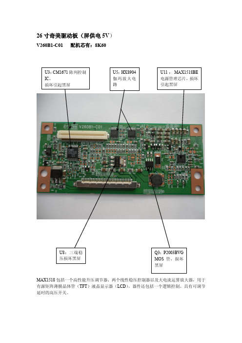
V260B1-C01 配机芯有:8K60MAX1518包括一个高性能升压调节器、两个线性稳压控制器以及大电流运算放大器,用于有源矩阵薄膜晶体管(TFT )液晶显示器(LCD )。
器件还包括一个逻辑控制、具有可调节延时的高压开关。
V315B3-C01 配机芯有8M19TPS65161的20、21、22:电源输入Vin; 此IC 与外围电配合可产生几路电压:VGH :23V V AAP :13.5V VGL :负5V VDA : VON : VOFF : VLOGIC :3.3V 等32寸奇美屏驱动板(屏供电12V )V320B1-C03 配机芯有:8M10FP5138:电源管理芯片,升压、降压、升降压转换IC ,驱动能力强,可以很好的提供LCD 屏正负偏设计方案,各组电压输出稳定,还可以适用于7—12寸LED 液晶屏背光升压垣流驱动。
有短路保护、开路保护、软启动功能,工作电压1.8—15V ,工作电流5.5mA 。
1脚:FB 反馈 2脚:SCP 保护/软启动 3脚:VCC 供电 4脚:CTL 控制 5脚:OUT 输出 6脚:GND 地 7脚:OSC 振荡 8脚:COMP 补偿V296W1-C1,X7 配机芯有:8TG5V296W1-C1逻辑板电路主要有三大部分组成:1.由U4(CM2651B-KQ )为核心的时序与逻辑控制电路,主要功能是将串行的LVDS 信号变成并行的控制信号,用于薄腊晶体管的控制或驱动;2.由U7—U11(HX8904TA 、HX8904SA )为核心的伽玛放大电路,主要是将伽玛信号进行适当的放大,控制薄膜晶体管,实现画面对比度的调整;3.由UP1(FA3269A V )为核心的DC-DC 变换电路,主是是将主板送来的5V 供电变成VGH (20V )、VDA (15V )、VGL (—5V )、V5V (5V )、VDD (3.3V )等等,用于屏驱动供电,此逻辑板损坏的最多的地方就是这部分,易损坏元件为UP1、QP5、DP3、UP2、RP37、LP2电感等等。
液晶屏逻辑电路板维修图

V260B1-C01 配机芯有:8K60MAX1518包括一个高性能升压调节器、两个线性稳压控制器以及大电流运算放大器,用于有源矩阵薄膜晶体管(TFT )液晶显示器(LCD )。
器件还包括一个逻辑控制、具有可调节延时的高压开关。
V315B3-C01 配机芯有8M19TPS65161的20、21、22:电源输入Vin; 此IC 与外围电配合可产生几路电压:VGH :23V V AAP :13.5V VGL :负5V VDA : VON : VOFF : VLOGIC :3.3V 等32寸奇美屏驱动板(屏供电12V )V320B1-C03 配机芯有:8M10FP5138:电源管理芯片,升压、降压、升降压转换IC ,驱动能力强,可以很好的提供LCD 屏正负偏设计方案,各组电压输出稳定,还可以适用于7—12寸LED 液晶屏背光升压垣流驱动。
有短路保护、开路保护、软启动功能,工作电压1.8—15V ,工作电流5.5mA 。
1脚:FB 反馈 2脚:SCP 保护/软启动 3脚:VCC 供电 4脚:CTL 控制 5脚:OUT 输出 6脚:GND 地 7脚:OSC 振荡 8脚:COMP 补偿V296W1-C1,X7 配机芯有:8TG5V296W1-C1逻辑板电路主要有三大部分组成:1.由U4(CM2651B-KQ )为核心的时序与逻辑控制电路,主要功能是将串行的LVDS 信号变成并行的控制信号,用于薄腊晶体管的控制或驱动;2.由U7—U11(HX8904TA 、HX8904SA )为核心的伽玛放大电路,主要是将伽玛信号进行适当的放大,控制薄膜晶体管,实现画面对比度的调整;3.由UP1(FA3269A V )为核心的DC-DC 变换电路,主是是将主板送来的5V 供电变成VGH (20V )、VDA (15V )、VGL (—5V )、V5V (5V )、VDD (3.3V )等等,用于屏驱动供电,此逻辑板损坏的最多的地方就是这部分,易损坏元件为UP1、QP5、DP3、UP2、RP37、LP2电感等等。
奇美夏普日立友达三星LG逻辑板维修
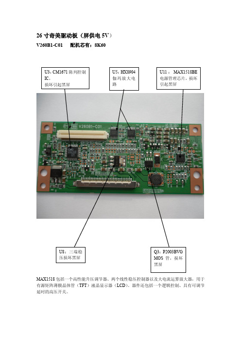
V260B1-C01 配机芯有:8K60MAX1518包括一个高性能升压调节器、两个线性稳压控制器以及大电流运算放大器,用于有源矩阵薄膜晶体管(TFT )液晶显示器(LCD )。
器件还包括一个逻辑控制、具有可调节延时的高压开关。
V315B3-C01 配机芯有8M19TPS65161的20、21、22:电源输入Vin; 此IC 与外围电配合可产生几路电压:VGH :23V V AAP :13.5V VGL :负5V VDA : VON : VOFF : VLOGIC :3.3V 等32寸奇美屏驱动板(屏供电12V )V320B1-C03 配机芯有:8M10FP5138:电源管理芯片,升压、降压、升降压转换IC ,驱动能力强,可以很好的提供LCD 屏正负偏设计方案,各组电压输出稳定,还可以适用于7—12寸LED 液晶屏背光升压垣流驱动。
有短路保护、开路保护、软启动功能,工作电压1.8—15V ,工作电流5.5mA 。
1脚:FB 反馈 2脚:SCP 保护/软启动 3脚:VCC 供电 4脚:CTL 控制 5脚:OUT 输出 6脚:GND 地 7脚:OSC 振荡 8脚:COMP 补偿V296W1-C1,X7 配机芯有:8TG5V296W1-C1逻辑板电路主要有三大部分组成:1.由U4(CM2651B-KQ )为核心的时序与逻辑控制电路,主要功能是将串行的LVDS 信号变成并行的控制信号,用于薄腊晶体管的控制或驱动;2.由U7—U11(HX8904TA 、HX8904SA )为核心的伽玛放大电路,主要是将伽玛信号进行适当的放大,控制薄膜晶体管,实现画面对比度的调整;3.由UP1(FA3269A V )为核心的DC-DC 变换电路,主是是将主板送来的5V 供电变成VGH (20V )、VDA (15V )、VGL (—5V )、V5V (5V )、VDD (3.3V )等等,用于屏驱动供电,此逻辑板损坏的最多的地方就是这部分,易损坏元件为UP1、QP5、DP3、UP2、RP37、LP2电感等等。
