福禄克FLUKE过程校准仪使用说明书
福禄克FLUKE过程校准仪使用使用说明
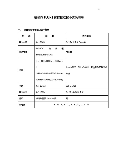
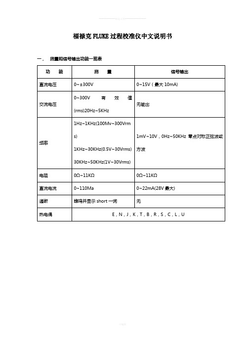
福禄克FLUKE过程校准仪中文说明书一,测量和信号输出功能一览表热电阻2,3,4线测量2线输出100ΩPlatinum(3926)100ΩPlatinum(385)120ΩNickel(672)200ΩPlatinum(385)500ΩPlatinum(385)1000ΩPlatinum(385)10ΩCopper(427)100ΩPlatinum(3916)压力27种压力模块从2.5kPa至69,000kPa *回路电压24或28V(22mA最大)*对于压力输出功能,是指由外部手动压力泵或其它压力源作为压力信号二、初识校准仪1.当你第一次取出校准仪,你需要将电池充电见图9,给电池充电2小时。
2.将电池放入校准仪中。
3.连接校准仪的电压输出端和输入端如下:连接最左端的一对插孔(V、Ω、RTD输出)和最右端的一对插孔(VMEAS)(见图3)。
图3 跨接线连接图4 输入输出的例子4.开机按⊙,按▲,▼以调整对比度。
以达到最好的显示效果。
校准仪在接通电源时是直流电压的测量功能,可以在一对VMEAS输入插孔中得到读数。
5.按看到其测量情况。
6.按V—…键,选择直流电压输出。
按数字键5和ENTER=开始输出5.0000V直流电压。
7.量直流电压。
你将在上半部屏幕看到测量读数,在下半部屏幕看到输出值,如图4所示。
三、操作功能1.输入和输出插孔图5所示,校准器输入和输出插孔,表2解释它的用途。
表2 输入/输出插孔和连接器7,8!SOURCE(输出)mA测量mAΩRTD插孔输出或测量电流、电阻和RTDS插孔,并提供回路电源9,10!SOURE(输出)V ΩRTD插孔输出电压、电阻、频率、和模拟RTDS输出插孔图5 输入/输出插孔和连接2.按键校准仪按键如图6所示,表3解释它们的功能,有4个未带标记的兰色按键,在显示屏幕下面称之为功能键。
其功能在操作过程中屏幕出现的定义所确定。
功能键和其显示内部在本手册中用黑体字标明,例如:Choices图6 按键表3 键的功能序号性能说明15 V-键测量方式中选择直流电压,输出方式中选择直流电压16 开关键电源开关3.显示屏幕图7为典型的显示屏幕。
Fluke CL543B 热敏电阻和热电偶校准仪说明书

U U se in the Plant, Field or Shop
• Includes Rubber Boot and mV Test Leads
Banana jacks for 2-, 3- and 4-wire RTD.
Thermocouple Source
Accuracy: ±(0.008% of setting + 0.006 mV)
Cold Junction Compensation: ±0.05°C (±0.09°F); thermistor traceable to NIST for 11 years
U Perform Heat Treating Surveys and Accuracy Tests • Meets or Exceeds the Requirement of AMS 2750 as Both a Secondary Standard Instrument and as a Field Test Instrument
Input resistance: ≥10 MΩ
RTD CONNECTIONS
Simulating or reading RTDs uses copper wire. Plug 2-, 3- or 4-wires into the corresponding jacks on the calibrator. For RTD source the CL543B simulates the (+) RTD from jacks 1 and 4 and the (-) RTD from jacks 2 and 3.
福禄克111校准步骤

FLUKE110、111、112型万用表校准步骤:一.转动的旋转开关到交流电压档“AC V”位置。
二.按住表背后凹陷处的校准按钮,该表响一次,即进入校准模式。
按下“Hz”按钮。
这些按钮的功能如下:按钮功能HOLD显示测量值。
MINMAX显示需要输入的值。
RANGE跳过不接受校准步骤的项输入信号。
如果你跳过校准步骤,它可能会使校准无效。
Hz接受输入信号,并开始下一个步骤。
也可以用来校准后退出校准模式,校正完成。
注意:在校准期间该测量值在屏幕上显示可能不准确。
如果旋钮设置不符合要求的校准步骤,那么目前的测量将是无效的。
即使旋钮在正确的位置是,目前的测量(报告时,HOLD 键被按下并保持)可能略有不同应用的信号,因为这将展示一个标定测量。
三.开始校准表1。
转动旋转开关至所需的校准功能。
(见校准设置在后面的函数的列表文件)注意:如果旋转开关的立场是错误的校准步骤完成后,响两次,您将无法继续进行校准过程2。
按校准步骤输入所需标准信号,按住MINMAX按钮查看显示屏上所需的值。
3。
等待测量出它的最终值,按住HOLD按钮来查看显示的测量值。
注意:这是一个标定测量,所以很可能是稍微不准确的,这是正常的。
4。
按Hz按钮进入下一个步骤。
该表记录了新的数据。
5。
重复步骤1到4,直到显示屏显示“End”,这表明该校准过程完成。
按下按钮“Hz”恢复正常运作,或关掉的仪表。
FLUKE111、112型校准功能表:步骤功能(开关位置)输入值频率(正弦波)保持时间(秒)C-01AC V-Hz 6.000V900.0Hz4C-02AC V 6.000V60Hz2C-03DC V 6.000V DC1C-04通断测量600Ω1C-05电阻Ω 6.000KΩ1C-06DC A使用安培插孔 6.000A1显示消息:如果校准程序没有完成,仪表将无法正常工作。
如果没有完成正确的校准,仪表显示“CaL”和“Err”,需要重新校准仪表。
如果出现以下信息表示该表已损坏,需要维修服务:•“CaL”和“Err”消息后,继续出现适当的重新校准。
FLUKE718压力校准仪说明书

页
1 2 6 8 9 9 14 16 17 17 18 18 18 19 20
i
718 30G/100G
用户手册 零件和附件 ............................................................................................................... 指标.......................................................................................................................... 压力感应器输入, 718 30G ..................................................................................... 压力感应器输入, 718 100G ................................................................................... 压力模块输入, 718 30G 和 718 100G .................................................................... 直流毫安输入, 718 30G 和 718 100G .................................................................... 回路电源 718 30G 及 718 100G ............................................................................ 综合指标 ............................................................................................................... 如何和 Fluke 联系 .....................................................................................................
fluke使用说明书
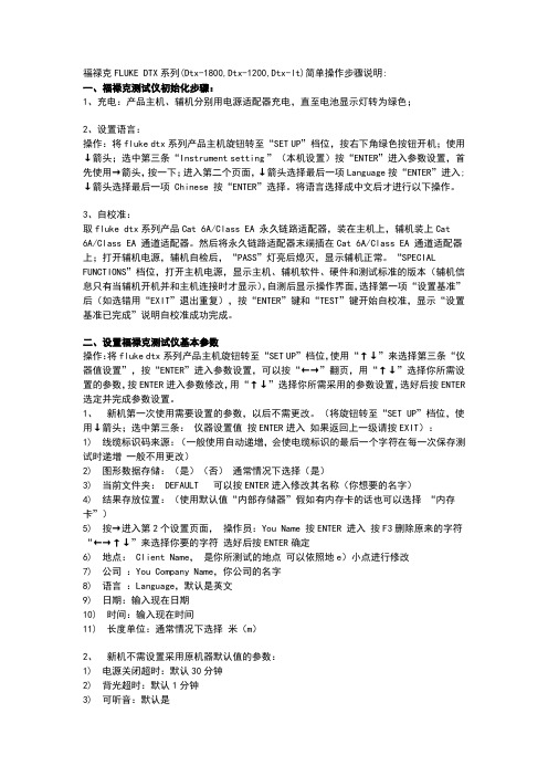
福禄克FLUKE DTX系列(Dtx-1800,Dtx-1200,Dtx-lt)简单操作步骤说明:一、福禄克测试仪初始化步骤:1、充电:产品主机、辅机分别用电源适配器充电,直至电池显示灯转为绿色;2、设置语言:操作:将fluke dtx系列产品主机旋钮转至“SET UP”档位,按右下角绿色按钮开机;使用↓箭头;选中第三条“Instrument setting ”(本机设置)按“ENTER”进入参数设置,首先使用→箭头,按一下;进入第二个页面,↓箭头选择最后一项Language按“ENTER”进入; ↓箭头选择最后一项 Chinese 按“ENTER”选择。
将语言选择成中文后才进行以下操作。
3、自校准:取fluke dtx系列产品Cat 6A/Class EA 永久链路适配器,装在主机上,辅机装上Cat6A/Class EA 通道适配器。
然后将永久链路适配器末端插在Cat 6A/Class EA 通道适配器上;打开辅机电源,辅机自检后,“PASS”灯亮后熄灭,显示辅机正常。
“SPECIAL FUNCTIONS”档位,打开主机电源,显示主机、辅机软件、硬件和测试标准的版本(辅机信息只有当辅机开机并和主机连接时才显示),自测后显示操作界面,选择第一项“设置基准”后(如选错用“EXIT”退出重复),按“ENTER”键和“TEST”键开始自校准,显示“设置基准已完成”说明自校准成功完成。
二、设置福禄克测试仪基本参数操作:将fluke dtx系列产品主机旋钮转至“SET UP”档位,使用“↑↓”来选择第三条“仪器值设置”,按“ENTER”进入参数设置,可以按“←→”翻页,用“↑↓”选择你所需设置的参数,按ENTER进入参数修改,用“↑↓”选择你所需采用的参数设置,选好后按ENTER 选定并完成参数设置。
1、新机第一次使用需要设置的参数,以后不需更改。
(将旋钮转至“SET UP”档位,使用↓箭头;选中第三条:仪器设置值按ENTER进入如果返回上一级请按EXIT):1) 线缆标识码来源:(一般使用自动递增,会使电缆标识的最后一个字符在每一次保存测试时递增一般不用更改)2) 图形数据存储:(是)(否)通常情况下选择(是)3) 当前文件夹: DEFAULT 可以按ENTER进入修改其名称(你想要的名字)4) 结果存放位置:(使用默认值“内部存储器”假如有内存卡的话也可以选择“内存卡”)5) 按→进入第2个设置页面,操作员:You Name 按ENTER 进入按F3删除原来的字符“←→↑↓”来选择你要的字符选好后按ENTER确定6) 地点: Client Name,是你所测试的地点可以依照地e)小点进行修改7) 公司:You Company Name,你公司的名字8) 语言:Language,默认是英文9) 日期:输入现在日期10) 时间:输入现在时间11) 长度单位:通常情况下选择米(m)2、新机不需设置采用原机器默认值的参数:1) 电源关闭超时:默认30分钟2) 背光超时:默认1分钟3) 可听音:默认是4) 电源线频率:默认50Hz5) 数字格式:默认是6) 将旋钮转至“SET UP”档位选择双绞线按ENTER 进入后 NVP 不用修改7) 光纤里面的设置,在测试双绞线是不须修改3、使用过程中经常需要改动的参数:将旋钮转至“SET UP”档位,选择双绞线,按ENTER进入:线缆类型:按ENTER进入后按↑↓选择你要测试的线缆类型例如我要测试超5类的双绞线在按ENTER进入后选择UTP 按ENTER ↑↓选择“Cat 5e UTP ” 按ENTER 返回。
FLUKE 多功能电气安全校准器 说明书
AmPac and Asia Regions VersionFLUKE Corporation / FLUKE International Corporation / PO Box 9090 / Everett WA 98206-9090 USA.(206) 356 5500 / FAX (206) 356-5116Page 1产品发布多功能电气安全校准器利用单台仪器校准和计量各种电气安全测试设备福禄克精密仪器部(FPM )发布了FLUKE5320A —— 一款多功能校准器,为各种各样的电气安全测试仪器的校准提供了齐全的功能和全面解决方案——高电压、大电流、大功率测量和驱动能力,所有这些都集成到了一台仪器内。
通过将多种功能集成到一台仪器,可以用一台校准器替代那些难以找得到的、高电压和大电流、大功率的电阻器和许多旧型号的仪器。
5320A 还包括一台精密数字多用表和电压校准器,可以完全校准多功能电气安装测试仪、兆欧表、环路测试仪、漏电保护测试仪、大地电阻测试、便携式电器设备测试仪、接地连接测试仪、医疗仪器电气安全测试仪,等等。
用户会对5320A 的精密度、可重复测量结果充满信心,并且会通过将5320A 与MET/CAL® Plus 校准管理软件相集成,实现自动化校准,从而实现生产力的大幅提高。
利用5320A 覆盖最多的被校准对象FLUKE 5320A 在单台仪器中集成了多种功能,可保证各种电气安全测试设备校准的产出效率和测量准确度。
谁是目标客户?主要的客户为直流/低频(DC/LF)校准实验室:第三方实验室内部校准实验室(公用事业部门、电信、电气制造厂商)部队/政府电气安全测试仪器制造商5320A的自动测试功能使其非常适合于生产测试和用于校准实验室。
被校准对象是什么?随着全球范围内电气安全标准的日益增多(包括英国的第16版测试标准和德国的VDE 0100及0700标准),电气安装和电器设备的测试成为电工和测试人员从事越来越多的常见任务。
福禄克7526A热工多产品校准器说明书

7526A热工多产品校准器一台仪器就可校准温度、压力及各种过程仪表和热工仪表7526A 热工多产品校准器可校准各类温度压力仪表、变送器以及过程仪表校准器精度更高配套更全方案更多校准更全集多用途、高精度、高价值于一身的台式热工多产品校准器7526A热工多产品校准器是性价比最高的台式校准器,用于校准各类压力和温度过程仪表。
7526A的隔离测量通道,可同时输出并测量电压、电流或电阻,从而更加简单方便地校准温度和压力变送器、热电阻及热电偶测温仪、压力表、数字过程仿真器、面板表、数据记录仪以及其他更多的热工仪表。
•输出和测量直流电压、电流、电阻、热电阻及热电偶•使用福禄克700系列或P系列压力模块测量压力•测量4-20mA环路电流•提供24V环路电压•利用自动开关测试功能测试压力和温度开关•热敏电阻测量至4 kΩ•每个输入/输出参数最多可储存9个可编程设置点•符合ITS-90温标的精密温度测量•兼容MET/CAL® Plus计量校准管理软件7526A 集多种功能于一身,可校准各类热工仪表。
其功能包括:•模拟和测量9种类型的热电阻及13种类型的热电偶•配合福禄克700系列或P系列压力模块,可测量压力至70 MPa•直流电压输出和测量准确度为读数的30ppm/ 50ppm •可输出和测量直流电阻至4 kΩ•直流电流输出0~100mA•测量直流电流0~50mA•提供24V直流环路电压7526A热工多产品校准器 3最符合过程仪表的需求当今,每一个过程仪表生产厂家都希望提高校准工作效率。
为保证产品质量,降低损耗,提高效率以及满足相关标准,测量过程控制参数的仪器,例如温度和压力仪器必须定期进行校准。
然而,选择一个既经济准确又可靠的校准器用于校准工作,不是一件容易的事。
现在7526A热工多产品校准器就提供了一种既准确、又经济、且功能多样的解决方案。
5Ω~4kΩ,准确度:±0.05℃*,支持Pt-100 (385,3926,3916),Pt-200,Pt-500,Pt-1000,Ni-120,Cu-427,SPRT热电偶测量/输出端子准确度:±0.1℃*,用户可选择内部/外部温度补偿支持热电偶类型B,C,E,J,K,L,N,R,S,T,U,XK,BP压力模块连接接口支持700系列和P系列压力模块,自动检测压力模块类型及量程四线RTD/Ω输入端子准确度:±0.02℃*隔离输入控制HART键启动250Ω环路电阻,使HART仪器读取7526A 热工多产品校准器 5温度传感器的计量校准校准温度变送器的电学部分只是全面校准的一部分。
福禄克网络测线仪使用说明书
FLUKE网络测试仪器说明书班级:330910姓名:***学号:********一、福禄克测试仪初始化步骤:1、充电:将Fluke dtx系列产品主机、辅机分别用电源适配器充电,直至电池显示灯转为绿色;2、设置语言:操作:将fluke dtx系列产品主机旋钮转至“SET UP”档位,按右下角绿色按钮开机;使用↓箭头;选中第三条“Instrument setting ”(本机设置)按“ENTER”进入参数设置,首先使用→箭头,按一下;进入第二个页面,↓箭头选择最后一项Language按“ENTER”进入; ↓箭头选择最后一项Chinese 按“ENTER”选择。
将语言选择成中文后才进行以下操作。
3、自校准:取fluke dtx系列产品Cat 6A/Class EA 永久链路适配器,装在主机上,辅机装上Cat 6A/Class EA 通道适配器。
然后将永久链路适配器末端插在Cat 6A/Class EA 通道适配器上;打开辅机电源,辅机自检后,“PASS”灯亮后熄灭,显示辅机正常。
“SPECIAL FUNCTIONS”档位,打开主机电源,显示主机、辅机软件、硬件和测试标准的版本(辅机信息只有当辅机开机并和主机连接时才显示),自测后显示操作界面,选择第一项“设置基准”后(如选错用“EXIT”退出重复),按“ENTER”键和“TEST”键开始自校准,显示“设置基准已完成”说明自校准成功完成。
二、设置福禄克测试仪基本参数操作:将fluke dtx系列产品主机旋钮转至“SET UP”档位,使用“↑↓”来选择第三条“仪器值设置”,按“ENTER”进入参数设置,可以按“←→”翻页,用“↑↓”选择你所需设置的参数,按ENTER进入参数修改,用“↑↓”选择你所需采用的参数设置,选好后按ENTER选定并完成参数设置。
三、福禄克测试仪测试过程:⒈根据需求确定测试极限值和电缆类型:通道测试还是永久链路测试?是CAT5E还是CAT6还是其他?⒉关机后将测试标准对应的适配器安装在主机、辅机上,如选择“TIA CAT5E CHANNEL”通道测试标准时,主辅机安装“DTX-CHA002”通道适配器,如选择“TIA CAT6A PERM.LINK”永久链路测试标准时,主辅机各安装一个“DTX-PLA002”永久链路适配器。
FLUKE 701 Loop Calibrator 说明书
校准器是一种 IEC 61010,CAT I 30 伏,污染第 2 级仪器。CAT I (I 类)仪器的设计使仪器能够承受高压、低能电源,例如电子电路或 复印机,产生的瞬态高压。
校准器功能
功能
量程
分辨率
测量 V dc(A dc(直流毫安) 输出 mA dc(直流毫安) 输出回路电源
显示 MEASURE mA(测量毫安)及 Loop Power(回路电源)。 2. 如下所示,以测试线探针接触载荷电路或电源。 若要退出 Loop Power(回路电源),更改测量模式。
707 LOOP CALIBRATOR
CAT 30V
COM
+
AMP06F.EPS
测量直流电压
W小心 为避免测试时损坏被测装置,确保在连接测试线之前,先将校准 器置于正确的模式。 若要测量直流电压:
缺省为关闭。
A
hij
按键依次通过模式: • Source mA(输出毫安) • Simulate mA(模拟毫安) • Measure mA(测量毫安) • Loop Power(回路电源)(24 伏) • Measure V dc(测量直流电压)
转动 n 增加或减少电流输出。
电流输出可按照 1 µA 或 100 µA 分辨率进行调整 (缺省值是 1 µA)。 • 要以 1 µA 为步长调整电流,转动旋钮即可。 • 要以 100 µA 为步长调整电流,按下并转动旋钮。
707 LOOP CALIBRATOR
CAT 30V
COM
+
AMP03F.EPS
用回路电源测量直流毫安
W小心 为避免测试时损坏被测装置,确保在连接测试线之前,先将校准 器置于正确的模式。 在回路电源档下,校准器能为变送器提供 +24 伏的回路电源,并同时 读出回路电流。 用回路电源测量直流毫安
Fluke 7526A 精密过程校准器说明书

FLUKE-71X.FLUKE-71XSales Guide7526A Precision Process CalibratorSales Training Guide – 7526A Precision Process CalibratorContents7526A PRECISION PROCESS CALIBRATOR (1)1.OBJECTIVE (3)2.INTRODUCTION (3)2.1.K EY F EATURES AT-A-GLANCE (3)2.2.P RODUCT P OSITIONING (3)2.3.7526A VS.525B (4)3.TARGET CUSTOMERS (4)4.KEY FEATURES (5)4.1.F EATURES AT-A-GLANCE (LEFT SIDE) (5)4.2.F EATURES AT-A-GLANCE (RIGHT SIDE) (6)4.3.S TANDBY /O PERATE MODE (7)4.4.HART C OMMUNICATIONS AND L OOP P OWER (7)4.5.T HERMOCOUPLE S OURCE AND M EASURE (8)4.6.I NTERNAL OR E XTERNAL CJC (8)4.7.RTD S OURCE AND M EASURE (8)4.8.P RESET S ETPOINTS (8)4.9.S WITCH T EST M ODE (9)4.10.P RESSURE M EASUREMENT (9)4.10.1.525A S ERIES P RESSURE M ODULES (9)4.10.2.700S ERIES P RESSURE M ODULES (10)PETITIVE COMPARISON (11)5.1.K EY SPECS/FEATURE COMPARISON (11)5.2.P RICE VS.P ERFORMANCE (12)5.3.H OW THE 7526A WINS (12)6.PRODUCT DEMONSTRATION (13)6.1.C URRENT/P RESSURE (I/P)T RANSMITTER (13)6.2.RTD M EASURE (14)7.SUMMARY SPECIFICATIONS (16)SUMMARY SPECIFICATIONS (CONT.) (17)8.ORDERING INFORMATION (18)9.SALES AND MARKETING MATERIALS (19)10.FAQ (20)Sales Training Guide – 7526A Precision Process Calibrator1. ObjectiveGet a quick introduction to the key product features, learn about the target industries andcustomers, see how the 7526A compares with the competition, learn how to perform a step-by-step product demonstration, and learn where to find available marketing materials.2. IntroductionThe Fluke Calibration 7526A, Precision Process Calibrator is a versatile benchtop calibrator designed for calibration of process instrumentation such as temperature and pressure transmitters, RTD and thermocouple readouts, pressure gauges, digital process simulators, data loggers, multimeters, etc. An isolated measurement channel allows the 7526A to simultaneously source and measure either voltage, current or resistance. Two LCD displays allow the user to view both input and output parameters simultaneously.2.1. Key Features at-a-glance∙ Sources and measures DC voltage, DC current, resistance, RTDs and thermocouples ∙ Measures pressure up to 10,000 PSI using Fluke 700 or 525A-P series pressure modules ∙ Measures 4-20 mA loop current∙ Sources 24 Vdc transmitter loop power∙ Tests pressure & thermal switches with unique automated switch-test function ∙ Measures thermistors up to 4 k Ω∙ Stores up to nine programmable setpoints for each input/output parameter ∙ Accepts ITS-90 coefficients for accurate SPRT measurementsCompatible with MET/CAL® Calibration Software2.2. Product PositioningThe 7526A is positioned in terms of price and performance between more expensive, high-end multi-product calibrators like the Fluke 5080A, and less precise, less versatile handheld field calibrators like Fluke process calibrators. It is capable of calibrating most handheld process calibration instrumentation such as loop calibrators, 3.5 digit DMMs, RTD/thermocouple simulators & readouts. It calibrates temperature andpressure transmitters and can calibrate most Documenting Process Calibrators (2:1 TUR relative to the Fluke 754).Fluke Calibration 7080AFluke 726 & 719Fluke Calibration 7526ASample 7526A workloadSales Training Guide – 7526A Precision Process Calibrator2.3. 7526A vs. 525BThe 7526A adds the functions and performance improvements listed in the table below. The 525B will continue to remain available to customers who do not need the additional features of the 7526A. US list price for the 7526A is about 10% higher than the 525B.3. Target CustomersThe 7526A primarily targets process manufacturers whose functions include: maintaining product quality, reducing waste, improving efficiency and conforming to regulatory standards. To accomplish these goals, field instrumentation used to monitor manufacturing processes must be maintained and calibrated regularly. Most field instrumentation such temperature/pressure transmitters, pressure gauges, RTD & thermocouple calibrators and readouts, and DMMs can be calibrated by the 7526A. Below is a summary by industry∙ Process manufacturers: QA Mgr., QC Inspector, Process Eng., Validation Eng., Compliance Mgr. ∙ Manufacturing: Mfg. Eng., Asset Mgr., Test Eng., Production Mgr. ∙ R&D: Design Engineer, Engineering Technician∙3rd party cal labs: Lab Manager, Calibration TechnicianSales Training Guide – 7526A Precision Process Calibrator4. Key features4.1. Features at-a-glance (left side)DC voltage output terminals ∙0 Vdc to 100 Vdc ∙Accuracy: 30 ppm (+3 μV)DC current output terminals ∙0 mA to 100 mA ∙Accuracy: 50 ppmRTD/Ω output terminals (two-wire) ∙ 5 Ω to 4 k Ω,∙Accuracy: ± 0.05 ºC, –200 to 630 ºCFour-wire RTD/Ω input terminals ∙Accuracy: ±0.02 ºC∙Pt 385, 100 Ω, –80 to 100 ºCIsolated pressure module input∙Accepts Fluke 700 & 525A series pressure modules Thermocouple input/output terminal∙Accuracy: ± 0.1 ºC∙–100 to 800 ºC (type K)Sales Training Guide – 7526A Precision Process Calibrator4.2. Features at-a-glance (right side)Isolated input terminalsAllows simultaneous source and measure ∙dc voltage (0 to 100 V)∙dc current measurement (0 to 50 mA) ∙Switch-test input∙24 V dc loop power supplyNumeric and secondary function keysIsolated input controls ∙dc voltage/current ∙Switch test mode ∙24 Vdc power supply ∙250 Ω HART resistor ∙Pressure input modeCursor controlsInput/Output Function Keys∙dc voltage/current ∙TC/RTD ∙Pressure mode ∙Unit type ∙Stby/Operate RS-232 PortGPIB IEEE-488Service port Chassis groundPower line voltage selector and fuse compartmentAC power inlet 120/240 ACPower switchStandard PC interface includes RS-232 and IEEE-488. A USB to serial adapter cable in included as standard.Sales Training Guide – 7526A Precision Process Calibrator4.3. Standby / Operate mode4.4. HART Communications and Loop PowerSTBY/OPR•In Standby mode , changes to the output value are not applied until you select the Operate mode•In Operate mode , each change to the output value is applied immediately•Voltages more than 30 V are not applied. The mode automatically reverts to Standby for safety•In Thermocouple mode, move through the thermocouple types (including millivolts)•In RTD/Ohms mode , move through the RTD types (including ohms)•In Pressure mode , move through the pressure units Select a secondary function from the numeric keypadSales Training Guide – 7526A Precision Process Calibrator4.5. Thermocouple Source and MeasureThe 7526A sources and measures all common thermocouple types and can display basic millivolts from -10.0 to 75.0 mV. See the extended specifications for the accuracy of each thermocouple type of a given temperature range.Thermocouple types include: B, C, E, J, K, L, N, R, S, T, U, XK, and BP.4.6.Internal or External CJCThe 7526A allows the user to select internal or external cold junction compensation forthermocouple temperature measurements. When external compensation is selected, XCJC is shown on the second line of the display. This mode simply disables the internal CJC and the 7526A will no longer monitor room temperature at the junction. When the internal CJC is disabled, an ice bath is used as a temperature source for the cold junction.4.7.RTD Source and MeasureThe 7526A both sources and measures most common types of RTDs and PRTs. The user can store CVD coefficients for up to five different probes and ITS-90 coefficients for one SPRT calibrated from –200 °C to 660 °C.RTD and thermistor types include:•Pt 385 100 Ω, 200 Ω, 500 Ω, 1000 Ω•Pt 3926 100 Ω•Pt 3916 (JIS) 100 Ω•Ni120 120 Ω•Cu 427 (Minco) 10 Ω•YSI 400 thermistorAlthough not listed above, an SPRT with a nominal resistance of 25.5 Ω can be measured when defined using ITS-90 coefficients.4.8.Preset SetpointsNine preset output setpoints can be stored and recalled for each output mode, including:•Voltage•Current•Each thermocouple type, including millivolts•Each of the five RTD definitionsThe setpoints can be recalled individually or can be cycled up and down with a user-defined dwell time at each setpoint. The automatic cycle feature starts at setpoint number 1 and steps to a user-specified end setpoint number. It then goes back down in reverse sequence and cycles through theSales Training Guide – 7526A Precision Process Calibratorsequence again. If the automatic cycle feature is used, the order of the setpoints must be stored in the desired sequence from setpoint 1 to the end setpoint.4.9.Switch Test ModeTo enter the Switch Test mode, the user presses and holds the Volts/mA key (right side of calibrator) for three seconds. After connecting the switch to the calibrator, the user cycles the switch over its range, first in one direction and then in the other. The 7526A will record the measured parameter where the switch changes state and displays the value. After cycling the switch both up and down, the calibrator will automatically display the “deadband,” or the range over which the switch does not actuate.4.10. Pressure MeasurementThe 7526A automatically recognizes either a Fluke 700 or 525A series pressure module whenconnected and automatically selects the appropriate range. Both displays show pressure at the same time but different units of measure can be displayed if desired.4.10.1.525A Series Pressure Modules4.10.2.700 Series Pressure Modulespetitive comparison5.1.Key specs/feature comparison Competitive ComparisonMake/ModelTC meas.accuracy(type K @ 0 C)RTD meas.accurcy(pt 385 @ 0 °C)Switchtest24V loopsupplyDCV,inputaccuracyDCV,outputaccuracyDCI,inputaccuracyDCI, outputrangeDCI, outputaccuracyResistanceinputaccuracyResistanceoutputaccuracyFluke 7526A0.10 °C0.02 °C yes yes 0.005%+ 0.2 uV0.003%+ 1 mV0.005%+ 1uA0 to 100 mA0.005 %+1uA0.004%+ 2 mΩ0.015 ΩFluke 525B0.16 °C0.02 °C no no no 0.003%+ 1 mVno0 to 100 mA0.005 %+1uA0.02 Ω0.015 ΩMartel 3001 0.14 °C0.02 °C no yes 0.005%+ 0.2 uV0.003%+ 1 mV0.005%+ 1uA0 to 100 mA0.005 %+1uA0.004%+ 2 mΩ0.015 ΩAmetek AMC9100.14 °C0.02 °C no yes 0.005%+ 0.2 uV0.003%+ 1 mV0.005%+ 1uA0 to 100 mA0.005 %+1uA0.004%+ 2 mΩ0.015 ΩOmega CL3001 0.14 °C0.02 °C no yes 0.005%+ 0.2 uV0.003%+ 1 mV0.005%+ 1uA0 to 100 mA0.005 %+1uA0.004%+ 2 mΩ0.015 ΩWika Mensor CED7000 0.14 °C0.02 °C no yes0.005%+ 0.2 uV0.003%+ 1 mV0.005%+ 1uA0 to 100 mA0.005 %+1uA0.004%+ 2 mΩ0.015 ΩFluke 7540.3 °C0.07 °C yes no 0.02%+ 50 uV0.01%+ 50 uV0.01%+ 20 uA22 mA0.02%+ 0.007 mA0.1%+ 10Ω0.02%+ 0.02 ΩBeamex MC50.1 °C (no CJC)0.06 °C yes yes0.02%0.02%0.02%0 to 25 mA0.02%0.02%+ 3.5 mΩ0.04%+ 3.5 mΩAOiP PJ 63010.3 °C n/a no no 0.015%+ 500 uV0.015%+ 500 uV0.02%+ 0.6uA0 to 60 mA0.02%+ 0.8uA0.01 %+ 80 mΩ0.01 %+ 100 mΩTongren TD7600 (to be discontinued)0.2 °C0.2 °C no no0.009%0.009%0.010% 1 to 100 mA0.01%= 7uA0.002%+ 30 mΩ0.8 ΩMeatest M5050.1% + 1 °C0.1% + 0.5 °C no no0.1%+ 1 digit0.05%+ 0.1%0.1%+ 1 digit0 to 22 mA0.05%+ 0.1%no0.1%+ 0.5 ΩEctron 11400.08 °C n/a no no0.0025%0.0025%no no no no no5.2. Price vs. Performancea documenting capability, are positioned below the 7526A.5.3. How the 7526A wins6.Product demonstrationWhat you decide to demonstrate will depend largely on the type of demo kit you purchased and the applicable accessories you have on hand. Due to its versatility, the 7526A can be easily demonstrated using common items you likely have in the office such as a 3.5 digit DMM, a temperature indicator or thermometer readout, a handheld pressure pump and pressure module, a common RTD or just about any thermocouple type with a mini-jack termination. Configuring the 7526A is intuitive and the Users Manual includes a section on applications (chapter 4) that illustrates how to connect most DUTs to the 7526A. Before doing any customer demonstration, ensure beforehand that you have all the necessary test leads to interface the DUT and the calibrator. The examples below are just a sampling of what you might consider for a customer demonstration.6.1.Current/Pressure (I/P) TransmitterRequired items include:▪Pressure source▪Pressure transmitter▪Pressure module▪Test leadsIn this example, the 7526A will source a 4-20 mA current to a pressure transmitter. The 7526A measures the corresponding pressure from the pressure module.1.Disconnect test leads from external devices.2.Select current output on the primary display (left side) by pressing Volts/mA to select dc voltageand current mode.3.If dc voltage mode is shown, push the key again to go to dc current mode.e the numeric keypad to type the necessary output value and push ENTER.5.Select pressure input on the isolated display (right side) by pressing the pressure key.6.If necessary, push the pressure key again to cycle through the pressure units until the desiredunit is shown.7.Attach the pressure module to the pressure source. Connect the Lemo connector from thepressure module to the pressure measurement input of the 7526A.8.Connect the transmitter to the calibrator as shown in the illustration.9.Press the STBY/OPR key to source current to the transmitter.10.To verify and calibrate the transmitter, refer to the transmitter documentation.6.2.RTD MeasureRequired items include:Four-wire RTD (e.g. 5615-9-S)In this example, a four-wire RTD (although technically incorrect, also referred to as an SPRT) is connected to the 7526A and ITS-90 coefficients are programmed into the calibrator. Using a Fluke Calibration drywell in this demonstration will allow you to cycle the RTD to different setpointtemperatures.The coefficients A- and B- refer to the A4 and B4 coefficients. These are generated when the SPRT is calibrated at the triple points of argon, mercury, and water. This includes the 83.8058 K (–189 °C) to 273.16 K (0 °C) subrange. Coefficients A, B, and C refer to different coefficients based on which subranges of the SPRT were calibrated. For example, if the 273.15 K (0 °C) to 933.473 K (660 °C) subrange was used, A, B, and C would refer to A7, B7, and C7 whereas if the 273.15 K (0 °C) to 692.67 K (420 °C) subrange was used, A and B would refer to A8 and B8 and C=0.To key in the deviation coefficients for a custom SPRT:1.Select RTD measure mode by pressing TC/RTD to select thermocouple and RTD/Ω mode. Ifthermocouple mode is shown, push the key again to go to RTD/Ω mode. If output mode isshown, push and to select input mode.2.Push TYPE/UNITS until the SPRT type is selected.3.Push ENTER to show the prompt “SET(1)/RECALL(2)”.4.Push to select custom SPRT data entry.5.At the “ENTER MIN TEMP” prompt, key in the minimum temperature limit for the SPRT, andpush ENTER.6.At the "ENTER MAX TEMP" prompt, key in the maximum temperature limit for the SPRT, andpush ENTER.7.At the "ENTER RTPW" prompt, key in the nominal resistance value (RTPW) for the SPRT, andpush ENTER.8.At the "ENTER COEFF A" prompt, key in the first (A) deviation coefficient for the SPRT, and pushENTER. To key in a coefficient that includes an exponent, key in the mantissa, push ENTER and to select the EXP function, key in the exponent and push ENTER.9.When prompted, use the same method to key in the second (B), third (C), fourth (A-), and fifth(B-) deviation coefficients.10.To abort the SPRT entry without stored changes, push TC/RTD.To use the SPRT:1.Select RTD measure mode as described above.2.Push TYPE/UNITS until the SPRT type is selected.3.Push ENTER to show the prompt "SET(1)/RECALL(2)".4.Push to recall the SPRT coefficients.7.Summary specificationsSee Extended Specifications for 90-day and 1-year specifications and specifications for all RTD and thermocouple types. Pressure specifications are determined by the module (see section 4.10.1 and 4.10.2 in this Sales Guide for module accuracy). Listed below are 1-year specifications and limited to more common RTD and thermocouple types. General specifications are included on the following page.Summary Specifications (cont.)8.Ordering informationEach 7526A includes the calibrator, Users Manual (CD ROM), Getting Started Guide, AC mains cord, thermocouple shorting jumper, traceable report of calibration, USB to serial cable adapter.9.Sales and Marketing Materials•The following sales and marketing materials are accessible from the 7526A Launch Page found at: /7526A-LaunchSales Training Guide – 7526A Precision Process CalibratorFluke Corporation Company ConfidentialPage 20 of 2010. FAQFLUKE-71X.FLUKE-71X。
Fluke 700 Series 文档记录过程校准器应用指南说明书
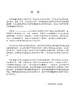
Application NoteBecause pressure is one of the more widely measured param-eters in process industries, it is a critical function of a document-ing process calibrator. Fluke’s pressure modules cover a wide range of pressures and maintain accuracy over a wide tempera-ture range, from 0°C to 50°C (32° F to 122°F). The pressure measurement portion of the Fluke 700 Series Documenting Process Calibrators is separate from the main unit to facilitate connection to fixed or bulky equipment and to provide mul-tiple pressure ranges for a single calibrator.A large selection of gage and differential modulesA family of 27 pressure modules covers the most common pres-sure calibrations from 0-10" H2O (0-2.5 kPa) to 0-10,000 psi(0-70,000 kPa).Gage pressure modules have one pressure fitting and measure the process pressure with re-spect to atmospheric pressure. Differential pressure modules have two pressure fittings and measure the difference between the applied pressure on the high fitting versus the low fitting. Each module is clearly labeled for range, overpressure specifi-cation, and materials compatibil-ity. A metric adapter is included with all but the P29 through P31 high pressure modules. Figure 1 shows the two types.Quick and easy measurements Fluke 700 Series pressure mod-ules are easy to operate. To measure pressure, the technician disconnects the pressure mea-suring transmitter from the process, plumbs the pressure module to a pressure source, and connects the pressure module cable to the calibrator. Pressure is applied, measured by the pres-sure module, and displayed digi-tally on the calibrator. At thetouch of a button, the pressuremay be displayed in any of 10different pressure units. Becausethe 700 Series calibrators cancapture readings electronically,there’s no need to write downresults. The calibrators automati-cally time-stamp and store allsaved measurements, savingtime, and eliminating errors asso-ciated with making manual nota-tions in the field. These self-documenting capabilities areimportant in ensuring accuratemaintenance. They are also veryhelpful in collecting calibrationdata to support compliance withdocumentation standards, includ-ing those established by OSHA,the FDA, the EPA, and ISO 9000.Pressure module performanceFluke 700 Series pressure mod-ules are highly accurate, withsimply stated specifications thatapply from 0% to 100% of fullspan and from 0°C to 50°C (32°Fto 122°F)—a factor that sets themapart from other pressure calibra-tors. Most ranges have total un-certainties of 0.05% of full scale(see Table 1, page 2).This performance is possiblethrough the innovative applica-tion of mathematics and micro-processor power. Fluke pressuremodules have silicon piezo-resistor sensors which consist ofa resistive bridge fabricated in asilicon diaphragm. Pressure ap-plied to the diaphragm causes achange in the balance of thebridge which is proportional tothe applied pressure. The bridgebalance change is not linear andis very sensitive to temperature.However, since these effects arequite stable with time andthrough repetitive changes ofcondition, the sensors can bevery accurate in measuring pres-sure over a wide temperaturerange, provided they are care-fully characterized.During manufacture, Flukepressure modules are character-ized by reading temperature andpressure at more than 100points. A least-squares regres-sion is used to calculate the coef-ficients of polynomial expressionfor pressure. The coefficients,unique to that pressure module,are stored in the module’smemory.Fluke 700 Series Pressure ModulesFigure 1. Gage and Differential pressure modulesEach module has its own microprocessor, allowing it to run the measurement circuitry and to communicate digitally with the calibrator. When con-nected to the calibrator, the coef-ficients are uploaded from the pressure module to the calibrator.Then, when pressure measure-ments are made, raw sensor values for pressure and tempera-ture are digitally loaded to the calibrator, where the raw sensor values and coefficients are manipulated to derive and dis-play the pressure reading. This innovative technique provides several benefits:1.Digital communication elimi-nates errors due to poor connections and electrical interference.2.The modules are inherently temperature-compensated from 0°C to 50°C (32°F to 122°F), with no derating for temperature effects.Figure 2. 700 Series Pressure Modules are overmolded with protective urethane and sealedagainst dirt, dust and moisture. All fittings are made of 316 stainless steel or Hastelloy C276and have internal mechanical supports3.The modules are fully inter-changeable because all signal processing is handled in the pressure module itself and then communicated to the calibrator in digitized form.Modules are calibrated inde-pendently of the calibrator,and can be used with any 700Series calibrator. Each module has its own serial number to facilitate traceability.Sensor protection in isolated modules Many of these modules (see Table 1) incorporate a stainless steel diaphragm to isolate the sensor.With these modules, any medium that is compatible with stainless steel can be used on the high side of the module.Rugged construction The pressure modules are de-signed to operate accurately and reliably despite the rough han-dling and harsh environmental conditions often found in process plants. A urethane overmolding protects against shock if a mod-ule is accidentally dropped and also seals against dirt, dust, and moisture. The module case is held together with screws con-nected to brass-reinforced seats,and all the pressure fittings,which are constructed of 316stainless steel, have internal mechanical supports. Pressure connections are 1/4" NPT. A BSP/ISO adapter is also provided on all but the P29, P30 and P31.Small and lightweight Since process technicians might need to carry two or more pres-sure modules along with the calibrator, the modules are small and lightweight.Remote sensor A one-meter cable between the pressure module and calibrator reduces the length of connecting tubing to the pressure source.The remote pressure head also provides an extra margin of safety and convenience by re-moving the calibrator and opera-tor from the pressure source.Table 1. Pressure specifications1Total uncertainty, % of full span for temperature range 0°C to +50°C, one year interval. Total uncertainty, 1.0% of full span for temperature range -10°C to 0°C, one year interval.2“Dry” indicates dry air or non-corrosive gas as compatible media. “316 SS” indicates media compatible with Type 316 Stainless Steel.“C276” indicates media compatible with Hastelloy C276.Use of pressure zero is required prior to measurement or source.Pressure units available are: psi, kPa, bar, in. Hg, mm Hg, in. H 2O (@4°C), ft. H 2O (@4°C), kg/cm 2, in. H 2O (@60°F), mm. H 2O (@4°C).Maximum overpressure specification includes common mode pressure.Modules are rated.Metric adapter(s): 1/4" NPT female to male BSP/ISO 1/4-19, tapered thread, included with all modules except P29, P30, and P31.Effective October 1996, all modules include a NIST traceable certificate and test data.Notes for 701 and 702 users only: Internal software V1.3 or later required. kg/cm 2, in. H 2O (@60°F), mm H 2O units not available.Not compatible with the PA and PV modules. Resolution in inches H 2O and kPa may vary from that shown in table.Documentation of results The scheduling of calibration, creation of procedures and documentation of your calibration results are facilitated by a number of instrumentation management software packages:•Fluke DPC/TRACK ™•™ InstruMint and DocuMint••T erminologyAbsolute pressure—absolute pressure measurements are referenced to zero pressure,(a perfect vacuum.)Absolute pressure transducer—a transducer that has an internal reference chamber sealed at or close to zero pressure (full vacuum) when exposed to atmospherea reading of approximately14.7 psi results.Boyle’s Law—the volume of a gas is inversely proportional to the pressure of the gas at con-stant temperature: V=1/P. Common mode pressure—the underlying common pressure (or static pressure) within a sys-tem from which a differential measurement is being made.D/P: Differential pressure, (pronounced DP)—other names used to mean the same thing are d/p cell, d/p transmitter and ∆P transmitter (where ∆ is delta or differential). This is the most common type of transmitter used in most process industries. It can be used to measure level, flow, pressure, differential pressure, and density or specific gravity. With some modifications, it can measure such things as tem-perature and oxygen purity. The d/p transmitter can be pneu-matic, electromechanical, or solid state. It can also be a smart transmitter. A typical large pro-cess plant can have hundreds or thousands of d/p transmitters in service.PSI—pounds per square inch(same as psig).PSIA—pounds per square inchabsolute.PSID—pounds per square inchdifferential.PSIG—pounds per square inchgage (same as psi).Square root extractor—aninstrument or software programthat takes the square root ofinput and puts the result on itsoutput. Square root extraction isneeded to linearize many flowsignals. Example: orifice plates,venturis, target flow meters, andpitot tubes all require thetransmitter’s output signal to belinearized. Mag flow meters,turbine flow meters, Dopplerflow meters, and vortex shed-ding flow meters don’t requiresquare root extraction.Static pressure—the zero-veloc-ity pressure at any arbitrarypoint within a system.Wet/dry differential—a differ-ential pressure transducer ortransmitter that uses a metaldiaphragm at the wet portwhere fluids can be applied, andno diaphragm at the dry port.The dry port exposes the sensormaterial to the medium, so onlyclean dry gas can be applied tothis port.Wetted parts—the diaphragmand pressure port material thatcomes in direct contact with themedium (gas, liquid).Gage pressure—the pressurerelative to atmospheric pressure.Gage pressure = absolute pres-sure minus one atmosphere.Gage pressure transducer—a transducer that measures pres-sure relative to atmosphericpressure.Ideal Gas Law—combiningBoyle’s Law and Charles’ Law,results in the Ideal Gas Law:PV=nrT, where nr is constant fora particular gas analogous to thenumber of molecules and therelative size of the molecule.I/P (I to P)—a current to pres-sure transmitter. A common in-strument in modern industrialplants. A typical large paper millor refinery could have 5,000 I/Psin use.Line pressure—the maximumpressure in the pressure vesselor pipe for differential pressuremeasurement.Orifice plate—a very low costand common primary sensingelement (PSE) for measuringflow. It must be used in conjunc-tion with a d/p cell. It creates aventuri and a resulting P isdeveloped across the platewhose square root is propor-tional to flow.P/I (P to I)—a pressure to cur-rent transducer.Pneumatic relay—refers to apneumatic instrument that per-forms a function to its input andprovides the result on its output(Example: square root extractor,adder, etc.).Fluke-700 PCK Calibration KitThe Fluke 700PCK Pressure Cali-bration Kit makes it possible to calibrate your pressure modules at your facility using your own precision pressure standards.The kit consists of a power sup-ply, an interface adapter, appro-priate cables, and Fluke 700PC Pressure Module Calibration soft-ware. When installed on your PC,the Windows ®-based software easily steps you through an as-found verification, a calibration adjustment, and an as-left verifi-cation. Calibration data is cap-tured for import to your database.A 386 or better PC, running Windows 3.1, is required, along with a precision pressure stan-dard with an uncertainty of less than 1/4 that of the pressure mod-ule being verified.Fluke Corporation PO Box 9090, Everett, WA USA 98206Fluke Europe B.V.PO Box 1186, 5602 BDEindhoven, The NetherlandsFor more information call:U.S.A. (800) 443-5853 orFax (425) 356-5116Europe/M-East (31 40) 2 678 200 or Fax (31 40) 2 678 222Canada (905) 890-7600 orFax (905) 890-6866Other countries (425) 356-5500©1998 Fluke Corporation. All rights reserved.Printed in U.S.A. 1/98 B0300UEN Rev C Printed on recycled paper.Figure 8. Calibration kit configuration.Fluke-700 PMP Pressure PumpThis hand operated pressure pump can provide pressures up to approximately 150 psi (1000 kPa)for calibration and troubleshoot-ing of pressure instrumentation.Figure 9. Pressure pump Fluke.Keeping your world up and running.。
Fluke 730G 730GA 730RG 压力校准仪 用户手册说明书

October 2018 (Simplified Chinese)© 2018 Fluke Corporation. All rights reserved. Specifications are subject to change without notice.All product names are trademarks of their respective companies.730G, 730GA, 730RGPressure Calibrators用户手册在正常使用和维护条件下,Fluke公司保证每一个产品都没有材料缺陷和制造工艺问题。
保证期为从产品发货之日起三(3)年。
部件、产品修理和服务的保证期限为90天。
本项保证仅向授权零售商的原始买方或最终用户提供,并且不适用于保险丝和一次性电池或者任何被Fluke公司认定由于误用、改变、疏忽、意外非正常操作和使用所造成的产品损坏。
Fluke公司保证软件能够在完全符合性能指标的条件下至少操作90天,而且软件是正确地记录在无缺陷的媒体上。
Fluke公司并不保证软件没有错误或无操作中断。
Fluke公司仅授权零售商为最终客户提供新产品或未使用过产品的保证。
但并未授权他们代表Fluke公司提供范围更广或内容不同的保证。
只有通过Fluke授权的销售商购买的产品,或者买方已经按适当的国际价格付款的产品,才能享受Fluke的保证支持。
在一个国家购买的产品被送往另一个国家维修时,Fluke公司保留向买方收取修理/更换零部件的进口费用的权利。
Fluke公司的保证责任是有限的,Fluke公司可以选择是否将依购买价退款、免费维修或更换在保证期内退回到Fluke公司委托服务中心的有缺陷产品。
要求保修服务时,请与就近的Fluke授权服务中心联系,获得退还授权信息;然后将产品连同问题描述寄至该服务中心,并预付邮资和保险费用(目的地离岸价格)。
Fluke对运送途中发生的损坏不承担责任。
福禄克Fluke dsp-40004300网络测试仪使用操作说明
福禄克Fluke dsp-4000/4300网络测试仪使用操作说明Fluke DSP4000/4300产品操作,福禄克DSP系列产品说明,操作步骤一、福禄克DSP系列产品使用步骤:1、充电:将福禄克DSP系列产品主机、辅机分别用变压器充电,直至电池显示灯转为绿色;2、自校准:取校准模块(上有DSP4000 CAL MODULE字样),用校准模块将主Fluke DSP4000/4300产品操作,福禄克DSP系列产品说明,操作步骤一、福禄克DSP系列产品使用步骤:1、充电:将福禄克DSP系列产品主机、辅机分别用变压器充电,直至电池显示灯转为绿色;2、自校准:取校准模块(上有“DSP—4000 CAL MODULE”字样),用校准模块将主机及辅机连接好。
打开辅机电源,辅机自检后,“PASS”灯亮后熄灭,显示辅机正常。
将旋钮开关转到任何模式即可打开主机电源,显示主机、辅机软件、硬件和测试标准的版本(辅机信息只有当辅机开机并和主机连接时才显示),自测后显示操作界面,将旋扭转至“SPECIAL FUNCTIONS”档位,用“↑↓”箭头选择第七项“SELF CALIBRATION”后(如选错用“EXIT”退出重复),按“ENTER”键和“TEST”键开始自校准,显示“SELF CALIBRATION COMPLETE”说明自校准成功完成。
3、设置参数:操作:将旋钮转至“SET UP”档位,在第一个黑块处按“ENTER”进入测试标准和电缆类型选择,常用的是“TIA CA T 5E CHANNEL”(超五类通道标准,使用通道适配器);“TIA CAT 6 CHANNEL”(六类通道标准,使用通道适配器),“TIA CAT 6 PERM LINK”(六类永久链路测试标准,使用永久链路适配器),其他不常用,用“↑↓”和“PAGE UP (3号按键)、PAGE DOWN(4号按键)”选择你所需的标准,按“ENTER”确认,回到主菜单。
福禄克FLUKE过程校准仪使用使用说明
福禄克FLUKE过程校准仪中文说明书一,测量和信号输出功能一览表热电阻2,3,4线测量2线输出100ΩPlatinum(3926)100ΩPlatinum(385)120ΩNickel(672)200ΩPlatinum(385)500ΩPlatinum(385)1000ΩPlatinum(385)10ΩCopper(427)100ΩPlatinum(3916)压力27种压力模块从2.5kPa至69,000kPa *回路电压24或28V(22mA最大)*对于压力输出功能,是指由外部手动压力泵或其它压力源作为压力信号二、初识校准仪1.当你第一次取出校准仪,你需要将电池充电见图9,给电池充电2小时。
2.将电池放入校准仪中。
3.连接校准仪的电压输出端和输入端如下:连接最左端的一对插孔(V、Ω、RTD输出)和最右端的一对插孔(VMEAS)(见图3)。
图3 跨接线连接图4 输入输出的例子4.开机按⊙,按▲,▼以调整对比度。
以达到最好的显示效果。
校准仪在接通电源时是直流电压的测量功能,可以在一对VMEAS输入插孔中得到读数。
5.按看到其测量情况。
6.按V—…键,选择直流电压输出。
按数字键5和ENTER=开始输出5.0000V直流电压。
7.量直流电压。
你将在上半部屏幕看到测量读数,在下半部屏幕看到输出值,如图4所示。
三、操作功能1.输入和输出插孔图5所示,校准器输入和输出插孔,表2解释它的用途。
表2 输入/输出插孔和连接器7,8!SOURCE(输出)mA测量mAΩRTD插孔输出或测量电流、电阻和RTDS插孔,并提供回路电源9,10!SOURE(输出)V ΩRTD插孔输出电压、电阻、频率、和模拟RTDS输出插孔图5 输入/输出插孔和连接2.按键校准仪按键如图6所示,表3解释它们的功能,有4个未带标记的兰色按键,在显示屏幕下面称之为功能键。
其功能在操作过程中屏幕出现的定义所确定。
功能键和其显示内部在本手册中用黑体字标明,例如:Choices图6 按键表3 键的功能序号性能说明15 V-键测量方式中选择直流电压,输出方式中选择直流电压16 开关键电源开关3.显示屏幕图7为典型的显示屏幕。
Fluke 9500B 示波器校准器 说明书
高性能、全自动、可升级的示波器校准器● 全自动的功能为您提供完全不用动手的示波器校准能力—能够校准当今高性能、多通道、具有多种功能的示波器。
● 连续升级的能力能够保护您的投资。
● 可以同时输出5个通道意味着你不再需要改接电缆线、不再需要复杂的多路信号切换器或者其它阻抗匹配网络。
● 高达6.4GHz 的稳幅正弦波和达70ps 的脉冲沿提供了校准今天和明天的高性能示波器时所需要的全部性能和灵活性。
● 福禄克独特的有源信号头技术能够在示波器的输入端产生校准信号—您可以不再怀疑波形的畸变到底发生在连接电缆上还是发生在示波器自身。
9500B示波器校准器高性能、全自动、可升级的示波器校准工作站示波器校准工作可能是很复杂,并且很耗费时间。
要完成这样的任务通常需要大量技术熟练的操作人员介入,而且今天的多通道示波器还常常意味着工作中需要进行大量的电缆换接。
甚至很多自动化的系统也需要大量的人工干预才能完成那些简单的校准工作程序。
更为值得注意的是用来实现自动化的开关系统或多路切换器常常会引入比被校准仪器更大的误差和畸变。
与这个问题相关联的是,示波器技术的迅速发展使得人们为追赶示波器的性能发展趋势,需要定期地进行大量的设备再投资才能满足校准示波器的要求。
Fluke 9500B 示波器校准工作站打破了这些常规。
无需手工干预、完全自动化、准确的示波器校准方案已经展现在每一个人的面前。
它具有您所需要的性能水平、您的财务预算能够支持的价格,而且还能够保证在今后需要的时候,通过性能的升级来满足您未来的需求。
2示波器校准工作的自动化可能是很多校准实验室提高校准工作效率的最迫切的要求。
用手工的方法来进行示波器校准工作需要技术熟练的技术人员花费大量的时间进行许多重复性的工作。
半自动或部分自动化的解决方案显然触及到了这个问题,能够把技术熟练的技术人员解脱出来以进行更有价值的工作。
然而,实际上这些方案也有其自身的问题。
在近10年的期间里,示波器已经从2通道的仪器演变成了更为复杂的4通道设备。
福禄克FLUKE过程校准仪使用说明书
福禄克FLUKE过程校准仪中文说明书一,测量和信号输出功能一览表热电阻2,3,4线测量2线输出100ΩPlatinum(3926) 100ΩPlatinum(385) 120ΩNickel(672) 200ΩPlatinum(385) 500ΩPlatinum(385) 1000ΩPlatinum(385) 10ΩCopper(427) 100ΩPlatinum(3916)压力27种压力模块从2.5kPa至69,000kPa*回路电压24或28V(22mA最大)*对于压力输出功能,是指由外部手动压力泵或其它压力源作为压力信号二、初识校准仪1.当你第一次取出校准仪,你需要将电池充电见图9,给电池充电2小时。
2.将电池放入校准仪中。
3.连接校准仪的电压输出端和输入端如下:连接最左端的一对插孔(V、Ω、RTD输出)和最右端的一对插孔(VMEAS)(见图3)。
图3 跨接线连接图4 输入输出的例子4.开机按⊙,按▲,▼以调整对比度。
以达到最好的显示效果。
校准仪在接通电源时是直流电压的测量功能,可以在一对VMEAS输入插孔中得到读数。
5.按看到其测量情况。
6.按V—…键,选择直流电压输出。
按数字键5和ENTER=开始输出5.0000V直流电压。
7.量直流电压。
你将在上半部屏幕看到测量读数,在下半部屏幕看到输出值,如图4所示。
三、操作功能1.输入和输出插孔图5所示,校准器输入和输出插孔,表2解释它的用途。
表2 输入/输出插孔和连接器7,8!SOURCE(输出)mA测量mAΩRTD插孔输出或测量电流、电阻和RTDS插孔,并提供回路电源9,10!SOURE(输出)V ΩRTD插孔输出电压、电阻、频率、和模拟RTDS输出插孔图5 输入/输出插孔和连接2.按键校准仪按键如图6所示,表3解释它们的功能,有4个未带标记的兰色按键,在显示屏幕下面称之为功能键。
其功能在操作过程中屏幕出现的定义所确定。
功能键和其显示内部在本手册中用黑体字标明,例如:Choices图6 按键表3 键的功能序号性能说明15V-键测量方式中选择直流电压,输出方式中选择直流电压16开关键电源开关3.显示屏幕图7为典型的显示屏幕。
Fluke 4180,Fluke 4181 说明书(使用手册)

4.1 温度设定菜单...................................................19 4.2 程序菜单.......................................................20
5 维护.................................................. 23
ii
表
表 1 所用符号........................................................2 表 2 规格...........................................................9 表 3 视温度限制.....................................................18
3.2.1 显示面板.......................................................... 11 3.2.2 显示屏............................................................ 13 3.2.3 后面板............................................................ 14 3.3 语言...........................................................16 3.3.1 言选择............................................................ 16 3.4 冰堆积物和清除程序(仅4180适用).................................16 3.4.1 结冰警告.......................................................... 16 3.4.2 清洗程序.......................................................... 16 3.4.3 除目标上的冰堆积物................................................ 17 3.5 红外温度计的发射率设置.........................................17 3.5.1 视温度设置限制.................................................... 17 3.6 通风和对流.....................................................18
Fluke T+ 和 T+ PRO 电气测试仪校准信息说明书

®P/N 2823862 July 2007© 2007 Fluke Corporation, All rights reserved. Printed in USA. All product names are trademarks of their respective companies.1T+ and T+ PROElectrical TesterCalibration InformationIntroductionThis document provides the following information for the T+ and T+ PRO Electrical Testers (hereafter referred to as the “Tester” or UUT): • Safety information • Symbols • Contacting Fluke • Specifications • Maintenance • Performance tests • Parts and accessories list • Product Warranty StatementFor complete operating instructions, refer to the T+ and T+ PRO Instruction Sheet .Safety InformationXW WarningTo avoid possible electric shock or personal injury, follow these guidelines:• Use the Tester only as specified in this document, otherwise the protection provided by the Tester may be impaired. • The Tester is to be used only by qualified personnel.• Do not use the Tester if it is damaged. Inspect the casebefore use. Look for cracks or missing plastic. Pay particular attention to the insulation surrounding the connectors. • Inspect the test leads for damaged insulation or exposed metal. Check the test leads for continuity. Replace damaged test leads before using the Tester. • Do not use the Tester if it operates abnormally. Protection provided by the Tester may be impaired. When in doubt, have the Tester serviced.T+ and T+ PRO Calibration Information2 •Do not operate the Tester around explosive gas, vapor, or dust.•Do not apply more than the rated voltage, as marked on the Tester, between terminals or between any terminal and earth ground.•When measuring hazardous voltage, verify the Tester’s operation by measuring a known voltage.•Only the test probes and batteries are serviceable. When servicing, use only specified replacement parts.•To determine the LEDs and beeper are working correctly, short the test leads together. The beeper sounds (if enabled) and all LEDs and display segments (T+ PRO) switch onbriefly indicating correct operation.•Comply with local and national safety requirements when working in hazardous locations.•Use proper protective equipment, as required by local or national authorities when working in hazardous areas. •Use caution when working above 30 V ac rms, 42 V peak, or60 V dc. Such voltages pose a shock hazard.•When using probes, keep fingers away from the probe tips. •Connect the common test lead before connecting the live test lead. When disconnecting the test leads, disconnect the live test lead first.•Do not operate the Tester with the battery door or portions of the cover removed or loosened.•When the batteries are depleted, self test will not function. •When the beeper is disabled, it will not sound until the beeper is reactivated.•For voltages above 240 V, you must only connect to a voltage source for a MAXIMUM of 30 seconds and then disconnect for a MINIMUM of 300 seconds.•Perform a self test before any measurements are taken for voltage, continuity, resistance, or rotary field. See “Self Test.” •Exercise caution when performing measurements on PLC inputs. When measuring relay control voltages on PLCs, be aware that this may open or close the relay/switch.W CautionAlthough the Tester may be used with depleted batteries, replace depleted batteries immediately to avoid Tester damage from battery acid leakage.Electrical TesterSymbols3SymbolsTable 1 describes the symbols that appear on the Tester or in this document.Table 1. SymbolsSymbol Explanation SymbolExplanationW Important information X Hazardous VoltageT Double insulated P Conforms to European Union Directives JEarth groundRContinuity beeper) Canadian Standards AssociationtUnderwriters Laboratories Certification~Do not dispose of this product as unsorted municipal waste. Visit Fluke’s Web site for recycling information.; N10140Conforms to relevant Australian standardsCAT III CAT III equipment is designed to protect against transients in equipment in fixed-equipment installations, such as distribution panels, feeders and short branch circuits, and lighting systems in large buildings.CAT IVCAT IV equipment is designed to protect against transients from the primary supply level, such as an electricity meter or an overhead or underground utility service.Contacting FlukeTo order parts, or for warranty service, contact Fluke as follows: USA: 1-888-99-FLUKE (1-888-993-5853) Canada: 1-800-36-FLUKE (1-800-363-5853) Europe: +31 402-675-200 Japan: +81-3-3434-0181 Singapore: +65-738-5655Anywhere in the world: +1-425-446-5500Or, visit Fluke's Web site at . To register your product, go to .SpecificationsTemperature PerformanceOperating ...........................................................−10 °C to 55 °C (14 °F to 131 °F) Storage...............................................................−30 °C to 60 °C (−22 °F to 140 °F) Relative Humidity90 %....................................................................0 °C to 30 °C (32 °F to 86 °F) 75 %....................................................................30 °C to 40 °C (86 °F to 104 °F) 45 %....................................................................40 °C to 50 °C (104 °F to 122 °F) AltitudeOperating............................................................2,000 m Storage...............................................................10,000 m Battery Type/Life ...................................................AAA (2); 40 hoursShock, Vibration ....................................................Sinusoidal vibration per MIL-PRF-28800F for a Class 2 instrument Safety .....................................................................ANSI/ISA S82.02.01, CSA C22.2-1010.1, IEC 61010-1 to 1000 V CATIII/600 V CAT IV AC Bandwidth .......................................................45 Hz to 66 HzT+ and T+ PRO Calibration Information4 Earth Ground.........................................................MAXIMUM working voltage 1000 V ac or dcMAXIMUM measurable voltage 600 V ac or dcThis will be displayed on the LED and LCD (T+ PRO)Duty Cycle.............................................................Indefinitely for voltages up to 240 V.For voltages between 240 V to 600 V, the duty cycle is 30 s on / 300 soff. For voltages above 240 V, the Tester must connect to a voltagesource only for a MAXIMUM of 30 s and then disconnect for aMINIMUM of 300 s.Voltage Hazard LED..............................................LEDs turn on @ voltages > 30 V ac/dc ± 35 % LEDs.......................................................................LEDs turn on @ between 70 % and 100 % of the indicated voltage onthe LED, except for the 12 V LED that turns on @ between 50 % and100 %.AccuracyAC voltage..........................................................± (3 % rdg + 2 digits)DC voltage..........................................................± (2 % rdg + 2 digits)Resistance..........................................................± (5 % rdg + 3 digits)LCD Resolution...................................................0.1 V for voltages < 50 V, 1 V for voltages ≥ 50 V, 0.01 kΩ atresistance measurementGFCI Test Current..............................................100 V to 150 V @ 6 mA to 9 mA ac150 V to 240 V < 12 mAStandard Input Test Current................................< 5 mASize (HxWxL).........................................................1.3 x 2.15 x 7.6 in. Weight....................................................................9.9 ozMaintenanceBasic maintenance for the Tester includes cleaning, checking the battery charge, and replacing depleted batteries.Cleaning the TesterXW WarningTo avoid electrical shock or damage to the Tester, never allowwater inside the case. To avoid damaging the Tester case,never use solvents on the Tester.If the Tester requires cleaning, wipe it down with a cloth that is lightly dampened with water or a mild detergent. Do not use aromatic hydrocarbons, chlorinated solvents, or methanol-based fluids when wiping down the tester. These cleaning agents will damage the Tester case.Testing the BatteriesPerform a self test, described later in this document, to determine the charge state of the batteries on the Tester. The self test will not work with depleted batteries. On T+ PRO Testers, the low battery icon ( B ) on the LCD indicates that the batteries need to be replaced.Replacing the BatteriesXW WarningTo avoid possible electric shock or personal injury:•Disconnect test leads from any electrical source before opening the battery compartment.•Do not operate the Tester with the battery door or portions of the cover removed or loosened.To replace the batteries, do the following:1.Remove the battery door by using a flat blade screwdriver to turn the battery doorfastener one-quarter turn counterclockwise.Electrical Tester Calibration Adjustment52. Observing proper polarity, replace the batteries with two new AAA alkaline batteries.3. Replace the battery door and secure it by turning the battery door fastener one-quarterturn clockwise.Calibration AdjustmentThe T+ and T+ Pro have no field calibration. If the UUT fails any performance test, contact Fluke Service for repair. See “Contacting Fluke .”Performance TestsXW WarningTo avoid possible electric shock, do not perform the performance test procedures unless the Tester is fully assembled and you are qualified to do so.The following performance tests verify the complete operation of the Tester and check theaccuracy of each Tester function against its specifications. The recommended calibration interval is 12 months. In the performance tests, the Tester is referred to as the unit under test (UUT). If the UUT fails any performance test, contact Fluke Service for repair. See “Contacting Fluke .” Required EquipmentTable 2 lists equipment that is required to complete the performance tests:Table 2. Equipment RequirementsEquipment Minimum Required Characteristics Recommended Model Calibratorac / dc voltage range: 10 V to 600 V Accuracy: ± 5 % Frequency 50/60 HzResistance range: 100 Ω to 9 k Ω Accuracy: ± 1.25 %)Fluke 5520A High Performance Multi-Product Calibrator or5500A Multi-Product Calibrator 3-phase power supply 120 V, 3-phase output Elgar 5250A or equivalent Digital multimeterac current range: 0 to 20 mA ± 7Fluke 189 Digital MultimeterSelf TestXW WarningTo avoid possible electric shock or personal injury:• Perform a self test before any measurements are taken for voltage, continuity, resistance, or rotary field. • When the batteries are depleted, self test will not function. Replace the batteries. W CautionAlthough the Tester may be used with depleted batteries,replace depleted batteries immediately to avoid Tester damage from battery acid leakage.To perform the self test, short the two probes. The self test lights all LEDs, and all LCD segments (T+ PRO). The beeper sounds (unless disabled) and the Tester switches to continuity mode. ToT+ and T+ PROCalibration Informationcomplete the self test, measure a known voltage before use. If the Tester fails self test, it must notbe used and requires service. See “Contacting Fluke.”Testing the LCD Display (T+ PRO)Use the following procedure to test the LCD display:NoteThe Tester must remain inactive for approximately 30 seconds beforeperforming the following test. This will force a processor reset that willdisplay all LCD segments for approximately 1 second at power up.1.Observe the LCD and short the test probes together. All LCD segments shown inFigure 1 should light.eqc001f.epsFigure 1. LCD DisplayTesting the LEDsUse the following procedure to test the LEDs:NoteThe Tester must remain inactive for approximately 30 seconds beforeperforming the following test. This will force a processor reset that willdisplay all LCD segments for approximately 1 second at power up.1.Short the test probes together.2.Observe that all LEDs light (voltage range, hazard, volts ac and dc, and continuity).Testing the Backlight (T+ PRO)Use the following procedure to test the backlight:1.Insert the test probes into a voltage source of > 10 V ac or dc.2.Observe that the backlight lights.Testing the Audible SignalUse the following procedure to test the audible signal:1.Short the UUT test probes together. The beeper should sound.2.If inactivated, press and hold Z until you hear three beeps.Testing the FlashlightUse the following procedure to test the flashlight:6Electrical TesterPerformance Tests71. Press the UUT headlight button.2. Observe that the flashlight turns on for approximately five seconds.Accuracy TestsPerform the accuracy and verification tests in Table 3.Table 3. T+ and T+ PRO Accuracy TestsStep Function Range Input ValueUUT Response(LED) LCD Display (T+ PRO) Measurement Limits1 Pos Off 12 V +20 V 12 V LED On - - - 2 Neg Off 12 V −20 V 12 V LED On - - - 3Pos On24 V+40 V+ LED On12 V, 24 V LED On Hazard On - - -4 Neg On 24 V −40 V − LED On12 V, 24 V LED On Hazard On - - -5 +10.5 V 12 V LED On 10.1 to 10.9 6−10.5 V12 V LED On−10.1 to −10.97 +48 V + LED On12 – 48 V LED OnHazard OnBeeper & Vibration On46.8 to 49.2 8dc V 0 – 50 V −48 V − LED On12 – 48 V LED On Hazard OnBeeper & Vibration On−46.8 to −49.29 +55 V+ LED On12 – 48 V LED OnHazard OnBeeper & Vibration On52 to 58 10 −55 V− LED On 12 – 48 V LED On Hazard OnBeeper & Vibration On −52 to −58 11 +590 V+ LED On12 – 600 V LED OnHazard OnBeeper & Vibration On576 to 604 12dc V 0 – 600 V−590 V − LED On12 – 600 V LED On Hazard OnBeeper & Vibration On −576 to −60413Digital DisplayVoltageMeasurementac V0 – 600 V55 V, 60 Hz ac LED On12 – 48 V LED On Hazard OnBeeper & Vibration On51 to 59T+ and T+ PRO Calibration Information8Table 3. T+ and T+ PRO Accuracy Tests (cont.)Step Function RangeInputValueUUT Response(LED)LCD Display (T+ PRO)Measurement Limits14 24 V 24 V 24 V LED On - - -15 120 V 120 V 120 V LED On - - -16 208 V 208 V 208 V LED On - - -17 240 V 240 V 240 V LED On - - -18 277 V 277 V 277 V LED On - - -19347 V(Canada)347 V 347 V LED On - - -20Voltage LEDs480 V 480 V 480 V LED On - - -21 Continuity 0 – 20 kΩShort Continuity LED On Continuity Sign22 Short None 0.00 to 0.0323 100ΩNone 0.06 to 0.1424Resistance0.00 – 9.99kΩ9 ΩNone 8.52 to 9.48Load Current TestTo test the load current, set up the UUT with equipment as shown in Figure 2 and complete the following procedure:1.Set the DMM to the mA dc function.2.Apply 600 V dc from the Source. The DMM reading should be < 5 mA.3.Apply −600 V dc from the Source. The DMM reading should be < 5 mA.Electrical TesterPerformance Testseqc90.epsFigure 2. Load Current/GFCI Current TestGFCI Trip TestTo test the GFCI Trip current accuracy, set up the UUT and equipment as shown in Figure 2, andcomplete the following procedure:NoteWhen you press the GFCI pushbutton, the resulting test will last for up toseven seconds.1.Set the DMM to the mA ac function.2.Apply 100 V, 60 Hz from the Source. The DMM reading should light the 12 – 48 VLEDs and Hazard symbol.3.Press the UUT GFCI pushbutton for one second. The UUT DC + and DC – LEDsshould alternately switch on and off while the beeper sounds. The DMM readingshould be between 6 and 9 mA ac during the test.Rotary Field Test (T+ PRO)To test the rotary field direction indicator, complete the following procedure:1.Connect the UUT to a 60 Hz, three-phase source of > 120 V, with the UUT red leadto A-phase and the UUT COM lead to B-phase. The UUT’s rotary field directionindicator arrow should point to the right.2.Move the UUT COM lead to C-phase. The rotary field direction indicator arrowshould point to the left.9T+ and T+ PRO Calibration Information10 Parts and Accessories ListTable 4 lists the replacement parts and accessories that are available from Fluke for the T+ andT+ PRO.Table 4. Replacement Parts and AccessoriesDescription Fluke Part NumberCalibration Information 2823862Battery Access Door 2558967Test Lead Set 2559535TP2 Replaceable Test Probe (black) 2637501TP2 Replaceable Test Probe (red) 2637512Limited Warranty and Limitation of LiabilityEach Fluke product is warranted to be free from defects in material and workmanship under normal use and service. The warranty period is two years and begins on the date of shipment. Parts, product repairs, and services are warranted for 90 days. This warranty extends only to the original buyer or end-user customer of a Fluke authorized reseller, and does not apply to fuses, disposable batteries, or to any product which, in Fluke's opinion, has been misused, altered, neglected, contaminated, or damaged by accident or abnormal conditions of operation or handling. Fluke warrants that software will operate substantially in accordance with its functional specifications for 90 days and that it has been properly recorded on non-defective media. Fluke does not warrant that software will be error free or operate without interruption.Fluke authorized resellers shall extend this warranty on new and unused products to end-user customers only but have no authority to extend a greater or different warranty on behalf of Fluke. Warranty support is available only if product is purchased through a Fluke authorized sales outlet or Buyer has paid the applicable international price. Fluke reserves the right to invoice Buyer for importation costs of repair/replacement parts when product purchased in one country is submitted for repair in another country.Fluke's warranty obligation is limited, at Fluke's option, to refund of the purchase price, free of charge repair, or replacement of a defective product which is returned to a Fluke authorized service center within the warranty period.To obtain warranty service, contact your nearest Fluke authorized service center to obtain return authorization information, then send the product to that service center, with a description of the difficulty, postage and insurance prepaid (FOB Destination). Fluke assumes no risk for damage in transit. Following warranty repair, the product will be returned to Buyer, transportation prepaid (FOB Destination). If Fluke determines that failure was caused by neglect, misuse, contamination, alteration, accident, or abnormal condition of operation or handling, including overvoltage failures caused by use outside the product’s specified rating, or normal wear and tear of mechanical components, Fluke will provide an estimate of repair costs and obtain authorization before commencing the work. Following repair, the product will be returned to the Buyer transportation prepaid and the Buyer will be billed for the repair and return transportation charges (FOB Shipping Point).THIS WARRANTY IS BUYER'S SOLE AND EXCLUSIVE REMEDY AND IS IN LIEU OF ALL OTHER WARRANTIES, EXPRESS OR IMPLIED, INCLUDING BUT NOT LIMITED TO ANY IMPLIED WARRANTY OF MERCHANTABILITY OR FITNESS FOR A PARTICULAR PURPOSE. FLUKE SHALL NOT BE LIABLE FOR ANY SPECIAL, INDIRECT, INCIDENTAL OR CONSEQUENTIAL DAMAGES OR LOSSES, INCLUDING LOSS OF DATA, ARISING FROM ANY CAUSE OR THEORY.Since some countries or states do not allow limitation of the term of an implied warranty, or exclusion or limitation of incidental or consequential damages, the limitations and exclusions of this warranty may not apply to every buyer. If any provision of this Warranty is held invalid or unenforceable by a court or other decision-maker of competent jurisdiction, such holding will not affect the validity or enforceability of any other provision.Fluke CorporationP.O. Box 9090Everett, WA 98206-9090U.S.A.Fluke Europe B.V.P.O. Box 11865602 BD EindhovenThe Netherlands11/99。
- 1、下载文档前请自行甄别文档内容的完整性,平台不提供额外的编辑、内容补充、找答案等附加服务。
- 2、"仅部分预览"的文档,不可在线预览部分如存在完整性等问题,可反馈申请退款(可完整预览的文档不适用该条件!)。
- 3、如文档侵犯您的权益,请联系客服反馈,我们会尽快为您处理(人工客服工作时间:9:00-18:30)。
福禄克FLUKE过程校准仪中文说明书测量和信号输出功能一览表1•当你第一次取出校准仪,你需要将电池充电见图9,给电池充电2小时。
2.将电池放入校准仪中。
3.连接校准仪的电压输出端和输入端如下:连接最左端的一对插孔(V、Q、RTD输出)和最右端的一对插孔(VMEAS (见图3)。
Figure 3-. Jumper Coniwctlon& for Demonstration HUKE Fouw l图3跨接线连接4.9999 V=5.0000 V-M(Te Fi<jur^4r Ueasurej'Soiirce Example图4输入输出的例子4. 开机按0,按4, ▼以调整对比度。
以达到最好的显示效果。
校准仪在接通电源时是直流电压的测量功能,可以在一对VMEA輸入插孔中得到读数。
5. 按|SETUp键,进入输出屏幕显示,校准仪将仍测量直流电压,并且你可以在显示屏顶部看到其测量情况。
6. 按V—…键,选择直流电压输出。
按数字键5和ENTER开始输出直流电压。
7. 按M EAS SOUR C键,进入双重显示屏幕。
测量、输出同时工作。
校准仪同时输出和测量直流电压。
你将在上半部屏幕看到测量读数,在下半部屏幕看到输出值,如图4所示。
三、操作功能1.输入和输出插孔图5所示,校准器输入和输出插孔,表2解释它的用途。
序号性能说明1外接电源插孔BE9005电源阻隔器插孔,可在交流电供工作室内使用。
本输入不能给电池充电。
2!串行接口连接校准仪与个人计算机。
3压力模块连接器连接校准仪与压力模块4TC输入/输出测量或模拟输出热电偶插孔。
本插孔接受微型扁平(中心距离或英寸)的电偶插头5,6!M E AS V插孔测量电压、频率、或三线或四线RTD(热电阻温度计)输入插孔7,8□SOURCE俞出)mA测量mA Q RTD插孔输出或测量电流、电阻和RTDS插孔,并提供回路电源9,10!S O URE(输出)V Q RTD 插孔输出电压、电阻、频率、和模拟RTDS俞出插孔表2输入/输出插孔和连接器图5输入/输出插孔和连接2. 按键校准仪按键如图6所示,表3解释它们的功能,有4个未带标记的兰色按键,在显示屏幕下面称之为功能键。
其功能在操作过程中屏幕出现的定义所确定。
功能键和其显示内部在本手册中用黑体字标明,例如:Choices图6按键3. 显示屏幕图7为典型的显示屏幕。
显示屏幕显示测量方式,紧靠上部显示为“输出关”,这一区域可显示其它方式(输出或测量)的状态。
其显示部分如下:•状态条:显示时间和日期(在设定方式下设置)同时还显示回路电源、电池储存和屏幕照明开关,所有这些功能都在设置模式中设定。
电池和屏幕照明不足也将在此处显示。
•模式指示器:显示仪器的设置工作状态,是在测量方式,输出方式还是在分割屏幕的测量/输出同时显示方式。
在每一个窗口中都对应着它的相应模式指示。
•测量值:按照你的选择显示工程单位或按百分比显示的测量值。
•量程状态:显示自动量程是否开通及当前所使用的量程。
•用户单位指示:指示所显示单位为用户单位,测量值或输出值的原始工程单位将不显示。
•附属显示:无论在使用缩放比或用户单位使用时,以原始工程单位显示测量或输出值。
Figure 7. Elements of a Typical Display图7典型显示屏幕四、设置校准仪使用带子和支架安装校准仪在您打开校准仪之后,请按图8所示将随机提供的带子依附在仪器上。
您可以按照需要调节带子以将校准仪悬挂至固实的支撑上。
图8还向您展示了在桌面上使用时,如何打开支架,从而将校准仪安装至适合观看的角度。
保持电池使用寿命可选的“自动省电”功能可以在超过设定的空闲时间之后将校准仪关闭。
“自动省电”功能的缺省设置是“关闭”。
当“自动省电”功能开启并且您在使用可选的镉镍电池组(型号BP7217)时,八图标会在显示屏的右上角显示。
在您关闭电源后,对“自动省电”功能的设置会仍然保留。
当使用电池电流转换装置时,“自动省电”功能同样会起作用。
请按照如下步骤开启“自动省电”功能。
1请按动setup。
2按动▼以显亮出现于Auto Battery Save 之后的Off。
3按动ENTER或者按动Choices软键。
4按动▲以显亮ON然后按动ENTER5若您接受显示屏上所显示的暂停时间,请到此停止。
请按动Done以终止设置模式而无需继续进行第6步。
6若您想改动暂停时间,请按动▼以显亮出现于Battery Save Timeout 之后的暂停时间。
7按动或者按动Choices软键。
8请以分钟为单位输入您选择的暂停时间(可接受的范围:1〜120分钟)。
9请按动Done软键。
10请按动Done或者setup以终止Setup模式当具备交流电源时,您可以使用可选的型号为BE9005的Fluke电池电流转换装置以节省电池能量。
当使用电池电流转换装置时,电池在内部是断开的,因而可以将其从校准仪卸除。
电池电流转换装置主要用于在工作台上对工艺仪表进行故障分析。
当您在校准仪表时,使用电池电源将获得最佳的结果。
选择显示语言此校准仪能以五种语言显示信息。
缺省语言是英语。
若您想更改显示语言,请按如下操作进行:1请按动setup。
2按动左边第三个软键两次。
3按动▼三次。
4按动ENTER5按动▲或者▼以显亮您选择的语言。
6请按动ENTER以确认您的选择。
现在您所选择的语言将是接通电源时的缺省语言。
7按动setup以终止Setup模式。
调节显示屏对比度请按动▲或者T以增加对比度。
按动▼或-则用于降低对比度。
当▲或▼键已被占用于从列表中选择条目,例如在Setup模式中时,此时请使用—或者T键调节对比度。
在Calculator 模式下,所有四个方向键都被用于算术功能。
显示日期和时间在正常操作中,显示屏的顶部可以显示日期和时间。
您可以在Setup模式下开启或者关闭日期和时间显示。
您还可以控制显示日期和时间的格式。
不管您是否使用日期和时间显示,您都应该设定日历和时钟,因为所有的已存储结果都应用了时间信息。
请按以下步骤设置日期和时间显示:1请按动setup。
2按动the Next Page 软键。
显示屏将显示如下:3使用▲或者▼键将光标移动至您想要更改的参数,然后按动〔ENTER或者Choice s软键以选择此参数的设定。
例如,在您选择Date Format后将会显示如下信息:4按动▲或者▼键以将光标移至您想要的日期格式。
5按动ENTER以返回[setup显示。
6重新开始另外一次选择,或者按动Done软键或者setup以保存您的设置并终止Setup模式。
五、测量模式提示操作模式(即MEASURESOURC模式)在显示屏上是以反向显示条的形式显示的。
如果校准仪未处于MEASUR模式,请按住|MEAS/SOURC直至MEASUR显示。
您必须处于MEASUR模式下才能对MEASUR参数进行更改。
测量范围此校准仪通常会自动改变到适合的测量范围。
显示屏的右下角视范围状态的不同而显示为“Range”或者"Auto Range ”。
Auto Range切换点在本手册最后的规格中有显示。
当您按动Range软键时,测量范围被锁定。
再次按动将循环至下一个测量范围并锁定。
当您选择另外一个测量功能时,Auto Range被重新激活。
如果测量范围已经锁定,超过此范围的输入将产生------- 的显示。
在Auto Range状态时,超过范围的输入将产生!!!!!!的显示。
测量电气参数当您开启校准仪时,它同时启动直流电压测量功能。
图10显示了电气测量连接。
若您想从SOURC或者MEASURE/SOUR模式选择电气测量功能,请首先按动|MEAS/SOUR~C进入MEASURE模式,然后按照如下步骤进行:1测量电流请按动mA测量直流电压请按动V-,测量交流电压请按动V~/HZ n一次,测量频率请按动|V~/HZ n 两次,测量电阻请按动“欧姆”。
提示当测量频率时,您会得到您所进行的测量要低于20赫兹的提示。
请按动▼以选择更低的频率范围,然后按动|ENTE R2请按照图10所示并依据测量功能的不同连接测试引线。
测试连续性当测试连续性时,当“欧姆”MWA插头和其普通插头之间的电阻晓宇25欧时,校准仪会发出报警声,并且显示屏会显示文字“Short ”。
当电阻大于400欧时,显示屏上会显示文字“Open”。
请按照如下步骤测试连续性:1请将要测试的电路去除电源。
2如有需要,请按动MEAS/SOURC以进入MEASUR模式。
3按动“欧姆”两次以使Open显示。
4请按照图10所示将校准仪连接至所要测量的电路。
5 •测量温度1)使用热电偶校准仪支持11种标准热电偶,每一种都对应有第一个字母表示:E, N, J , K T, B, R, S,C丄或者U表5概括了这些热电偶的范围和特性。
使用热电偶测量温度,请按下列步骤进行:(1)将热电偶导线与相应的TC微型插头相连,然后按图13所示插到TC插孔。
一个插头比另一个宽些。
不要用力将微型插头插入错误的极性中去。
(2)如需要,按M EAS SOUR C选择MEASUR方式。
(3)按TCRTD。
按照屏幕提示去选择热电偶的类型。
(4)使用▲或▼键随后按|ENTER=选择相应的TC类型。
(5)如需要,可按下列在|SETUp方式选择c或T温度单位。
a. 按SETUPb. 按Next Page功能键两次c. 使用▲或▼键移动光标至需改变的参数,然后按ENTER或Choices功能键选择设定参数。
d. 按▲或▼移动光标至所希望的设定值。
e. 按ENTER反回到SETUP显示屏幕。
f. 按Done功能键或者SETUP退出SETUP模式。
(6)如需要,可在SETUP模式下改变ITS-90或IPTS-68温度标准,步骤与上述a~f所述相同。
7441.3” V.'U'WJFigure 13.urinj T&mp9ratun> vritha Thonrwuoupk2)使用铂电阻-温度检测计(RTDS如表6所示,校准仪所接受的RTD类型。
RTDs在0C(32 T )的阻值称为“冰点”或R0b 最常用的R0为100Q。
大部分RTDs检测取自三端结构。
校准仪以两线、三线或四线制连接接受RTD测量输入信号。
其中四线制测量方式精度最高。
两线制测量方式精度最低。
(1)如需要,按M EAS SOUR C选择MEASUR模式。
(2 )按TCRTD两次选择RTD类型显示屏幕。
(3 )按▲或▼选择所希望的RTD类型。
(4)按|ENTE R=(5)按▲或▼选择2 —,3—, 4 —线制连接。
(6)按显示或如图15所示,将RTD插入输入插孔。
如使用3线制连接,请在mA Q RTDMEAS F面的插孔和V MEAS下面的插孔(如图所示)使用提供的跨接线。