建筑土木毕业设计中英文翻译--新型高层建筑物结构交错排列剪力墙结构
土木工程专业外文翻译--高层建筑

外文原文Tall BuildingsAlthough there have been many advancements in building construction technology in general, spectacular achievements have been made in the design and construction of ultrahigh-rise buildings.The early development of high-rise buildings began with structural steel framing. Reinforced concrete and stressed-skin tube systems have since been economically and competitively used in a number of structures for both residential and commercial purposes. The high-rise buildings ranging from 50 to 110 stories that are being built all over the United States are the result of innovations and development of new structural systems.Greater height entails increased column and beam sizes to make buildings more rigid so that under wind load they will not sway beyond an acceptable limit. Excessive lateral sway may cause serious recurring damage to partitions, ceilings, and other architectural details. In addition, excessive sway may cause discomfort to the occupants of the building because of their perception of such motion. Structural systems of reinforced concrete, as well as steel, take full advantage of the inherent potential stiffness of the total building and therefore do not require additional stiffening to limit the sway.In a steel structure, for example, the economy can be defined in terms of the total average quantity of steel per square foot of floor area of the building. Curve A in Fig. 1 represents the average unit weight of a conventional frame with increasing numbers of stories. Curve B represents the average steel weight if the frame is protected from all lateral loads. The gap between the upper boundary and the lower boundary represents the premium for height for the traditional column-and-beam frame; Structural engineers have developed structural systems with a view to eliminating this premium.Systems in steel. Tall buildings in steel developed as a result of several types of structural innovations. The innovations have been applied to the construction of both office and apartment buildings.Frames with rigid belt trusses. In order to tie the exterior columns of a frame structure to the interior vertical trusses, a system of rigid belt trusses at mid-height and at the top of the building may be used. A good example of this system is the First Wisconsin Bank Building (1974) in Milwaukee.Framed tube. The maximum efficiency of the total structure of a tall building, for bothstrength and stiffness, to resist wind load can be achieved only if all column elements can be connected to each other in such a way that the entire building acts as a hollow tube or rigid box in projecting out of the ground. This particular structural system was probably used for the first time in the 43-story reinforced concrete DeWitt Chestnut Apartment Building in Chicago. The most significant use of this system is in the twin structural steel towers of the 110-story World Trade Center building in New York.Column-diagonal truss tube. The exterior columns of a building can be spaced reasonably far apart and yet be made to work together as a tube by connecting them with. Diagonal members intersecting at the center line of the columns and beams. This simple yet extremely efficient system was used for the first time on the John Hancock Center in Chicago, using as much steel as is normally needed for a traditional story building.Fig. 1. Graphical relationship between design quantities of steel and building heights for a typical building frame. Curves A and B correspond to the boundary conditions indicated in the two building diagrams. 1 psf = 0. 048kPa.Bundled tube. With the continuing need for larger and taller buildings, the framed tube or the column-diagonal truss tube may be used in a bundled form to create larger tube envelopes while maintaining high efficiency. The i10-story Sears Roebuck Headquarters Building in Chicago has nine tubes, bundled at tile base of the building in three rows. Some of these individual tubes terminate at different heights of the building, demonstrating the unlimited architectural possibilities of this latest structural concept. The Sears tower, at a height of 1450 ft (442 m), is the world's tallest building.Stressed-skin tube system. The tube structural system was developed for improving the resistance to lateral forces (wind or earthquake) and the control of drift (lateral building movement) in high-rise building. The stressed-skin tube takes the tube system a step further. The development of the stressed-skin tube utilizes the facade of the building as a structural element which acts with the framed tube, thus providing an efficient way of resisting lateral loads in high-rise buildings, and resulting in cost-effective column-free interior space with a high ratio of net to gross floor area.Because of the contribution of the stressed-skin facade, the framed members of the tube require less mass, and are thus lighter and less expensive. All the typical columns and spandrel beams are standard rolled shapes, minimizing the use and cost of special built-up members. The depth requirement for the perimeter spandrel beams is also reduced, and the need for upset beams above floors, which would encroach on valuable space, is minimized.The structural system has been used on the 54-story One Mellon Bank Center in Pittsburgh.Systems in concrete. While tall buildings constructed of steel had an early start, development of tall buildings of reinforced concrete progressed at a fast enough rate to provide a competitive challenge to structural steel systems for both office and apartment buildings.Framed tube. As discussed above, the first framed tube concept for tall buildings was used for the 43-story DeWitt Chestnut Apartment Building. In this building, exterior columns were spaced at 5.5-ft (1.68-m) centers, and interior columns were used as needed to support the 8-in.-thick (20-cm) flat-plate concrete slabs.Tube in tube. Another system in reinforced concrete for office buildings combines the traditional shear wall construction with an exterior framed tube. The system consists of an outer framed tube of very closely spaced columns and an interior rigid shear wall tube enclosing the central service area. The system (Fig.2), known as the tube-in-tube system, made it possible to design the world's present tallest (714 ft or 218m) lightweight concrete Building in Houston)for structure of only 35 s oriel building the unit 52 —story One Shell Plaza of a traditional shear wallSystems compiling both concrete and steel have also been developed ,an example of which is the composite system developed by Skidmore ,Owings & Merrill in which an exterior closely spaced framed tube in concrete envelops an interior steel framing ,thereby combining the advantages of both reinforced concrete and structuralsteel systems.The 52—story One Shell Square Building in New Orleans is based on this system.NEW WORDS AND PHRASES1.spectacular 壮观的,惊人的,引人注意的2.sway 摇动,摇摆,歪,使倾斜3.residential 居住的,住宅的,作住家用的4.commercial 商业的,商业上的,商务的5.innovation 革新,创新,新方法,新事物6.boundary 分界线,边界7.eliminate 排除,消除,除去8.apartment 公寓住宅,单元住宅9.column 柱,支柱,圆柱,柱状物10.demonstrate 示范,证明,演示,11.project 凸出,投射,计划,工程12.stress 应力,压力13.truss 构架,桁架14.bundle 捆,束,包15.terminate 使终止,使结尾,结束16.facade (房屋的)/E 面,立面,表面17.perimeter 周,周围,周界,周长18.encroach 侵犯,侵占,蚕食19. high • rise building 高层建筑20.reinforced concrete 钢筋混凝土21 . spandrel beam 窗下墙的墙托梁22. shear wall 剪力墙中文译文高层建筑大体上建筑施工工艺学方面已经有许多进步, 在超高层的设计和施工上已经取得了惊人的成就。
毕业论文外文翻译-高层建筑结构
毕业论文外文翻译-高层建筑结构High-Rise Building StructureAbstract:High-rise buildings have become common in modern cities across the world. Structural considerations play a crucial role in the planning and design of these buildings. The structural system of a high-rise building must be able to support its own weight as well as any additional loads imposed by occupancy and natural forces such as wind and earthquakes. This paper provides an overview of the structural systems commonly used in high-rise buildings, including reinforced concrete, steel, and hybrid systems. It also discusses the advantages and disadvantages of each system and the factors that affect their selection based on the specific requirements of a building.Introduction:In modern cities, high-rise buildings have become an increasingly popular option for meeting the growing need for office and residential space. High-rise buildings have several advantages, including the efficient use of land, the ability to accommodate large numbers of people, and the provision of spectacular views. To achieve these benefits, it is important to develop a safe and efficient structural system for high-rise buildings.Structural Considerations for High-Rise Buildings:Structural considerations are critical for high-rise buildings. Such structures must be able to support their own weight, as well as resist loads imposed by occupancy and natural forces such as wind and earthquakes. The structural system must also be able to maintain stability throughout the building's lifespan, while providing adequate safety for its occupants.Common Structural Systems for High-Rise Buildings:Reinforced Concrete System:One of the most commonly used structural systems for high-rise buildings is reinforced concrete. This system is desirable because of its strength, durability, and fire resistance. Concrete is also easily moldable, which allows for various shapes and sizes to be used in the building design.Steel System:The steel structural system is another popular choice for high-rise buildings. Steel structures have a high strength-to-weight ratio, which makes them a good choice for taller and lighter buildings. They are also easily adaptable and have high ductility, making them more resistant to earthquake damage.Hybrid System:Hybrid structural systems, which combine the advantages of reinforced concrete and steel, have become increasingly popular in recent years. These systems include concrete encased steel frames, concrete-filled steel tubes, and steel reinforced concrete.Factors Affecting Selection:The selection of a structural system for a high-rise building depends on several factors, including the building height, location, climate, design requirements, and budget. For example, in areas with high wind loads, a steel or hybrid system may be preferable due to its high strength and ductility. In areas with high seismic activity, a reinforced concrete system may be more appropriate because of its superior resistance to earthquake damage.Advantages and Disadvantages of Structural Systems:Each structural system has its advantages and disadvantages. The reinforced concrete system is strong, durable, and fire resistant, but is also heavy and requires a longer construction period. The steel system is adaptable and has a high strength-to-weight ratio, but is also susceptible to corrosion and may require regular maintenance. The hybrid system combines the benefits of both systems but may be more expensive than either system alone.Conclusion:Structural considerations are critical for the planning and design of high-rise buildings. Reinforced concrete, steel, and hybrid systems are the most commonly used structural systems for high-rise buildings. The selection of a system depends on several factors, including the building height, location, climate, design requirements, and budget. Each system has its advantages and disadvantages, and careful consideration of these factors is necessary to develop a safe and efficient structural system for high-rise buildings.。
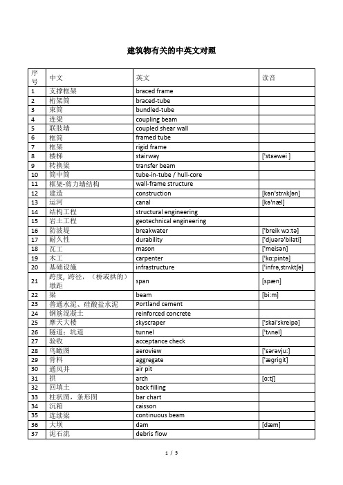
和建筑物有关的英文单词
36
大坝
dam
[dæm]
37
泥石流
debris flow
38
施工图设计,详图设计
detail design
39
土压力
earth pressure
40
抗震设计
earthquake-resistant design
41
屋檐,檐
eaves
[i:vz]
42
构件
element
['elimənt]
127
杆
pole
[pəul]
128
圆柱
column
['kɔləm]
129
抗拉强度
tensile strength
130
压力
compressive force
131
弯曲,弯折;挠度
bending
['bendiŋ]
132
扭曲;翘曲
twisting
['twistiŋ]
133
复合材料
composite material
['infrə,strʌktʃə]
21
跨度, 跨径,(桥或拱的)墩距
span
[spæn]
22
梁
beam
[bi:m]
23
普通水泥、硅酸盐水泥
Portland cement
24
钢筋混凝土
reinforced concrete
25
摩天大楼
skyscraper
['skai'skreipə]
26
隧道;坑道
tunnel
土木工程毕业设计外文翻译原文+翻译

The bridge crack produced the reason to simply analyseIn recent years, the traffic capital construction of our province gets swift and violent development, all parts have built a large number of concrete bridges. In the course of building and using in the bridge, relevant to influence project quality lead of common occurrence report that bridge collapse even because the crack appears The concrete can be said to " often have illness coming on " while fracturing and " frequently-occurring disease ", often perplex bridge engineers and technicians. In fact , if take certain design and construction measure, a lot of cracks can be overcome and controlled. For strengthen understanding of concrete bridge crack further, is it prevent project from endanger larger crack to try one's best, this text make an more overall analysis , summary to concrete kind and reason of production , bridge of crack as much as possible, in order to design , construct and find out the feasible method which control the crack , get the result of taking precautions against Yu WeiRan.Concrete bridge crack kind, origin cause of formation In fact, the origin cause of formation of the concrete structure crack is complicated and various, even many kinds of factors influence each other , but every crack has its one or several kinds of main reasons produced . The kind of the concrete bridge crack, on its reason to produce, can roughly divide several kinds as follows :(1) load the crack caused Concrete in routine quiet .Is it load to move and crack that produce claim to load the crack under the times of stress bridge, summing up has direct stress cracks , two kinds stress crack onces mainly. Direct stress crack refer to outside load direct crack that stress produce that cause. The reason why the crack produces is as follows, 1, Design the stage of calculating , does not calculate or leaks and calculates partly while calculating in structure; Calculate the model is unreasonable; The structure is supposed and accorded with by strength actually by strength ; Load and calculate or leak and calculate few; Internal force and matching the mistake in computation of muscle; Safety coefficient of structure is not enough. Do not consider the possibility that construct at the time of the structural design; It is insufficientto design the section; It is simply little and assigning the mistake for reinforcing bar to set up; Structure rigidity is insufficient; Construct and deal with improperly; The design drawing can not be explained clearly etc.. 2, Construction stage, does not pile up and construct the machines , material limiting ; Is it prefabricate structure structure receive strength characteristic , stand up , is it hang , transport , install to get up at will to understand; Construct not according to the design drawing, alter the construction order of the structure without authorization , change the structure and receive the strength mode; Do not do the tired intensity checking computations under machine vibration and wait to the structure . 3, Using stage, the heavy-duty vehicle which goes beyond the design load passes the bridge; Receive the contact , striking of the vehicle , shipping; Strong wind , heavy snow , earthquake happen , explode etc.. Stress crack once means the stress of secondary caused by loading outside produces the crack. The reason why the crack produces is as follows, 1, In design outside load function , because actual working state and routine , structure of thing calculate have discrepancy or is it consider to calculate, thus cause stress once to cause the structure to fracture in some position. Two is it join bridge arch foot is it is it assign " X " shape reinforcing bar , cut down this place way , section of size design and cut with scissors at the same time to adopt often to design to cut with scissors, theory calculate place this can store curved square in , but reality should is it can resist curved still to cut with scissors, so that present the crack and cause the reinforcing bar corrosion. 2, Bridge structure is it dig trough , turn on hole , set up ox leg ,etc. to need often, difficult to use a accurate one diagrammatic to is it is it calculate to imitate to go on in calculating in routine, set up and receive the strength reinforcing bar in general foundation experience. Studies have shown , after being dug the hole by the strength component , it will produce the diffraction phenomenon that strength flows, intensive near the hole in a utensil, produced the enormous stress to concentrate. In long to step prestressing force of the continuous roof beam , often block the steel bunch according to the needs of section internal force in stepping, set up the anchor head, but can often see the crack in the anchor firm section adjacent place. So if deal with improper, in corner or component form sudden change office , block place to be easy to appear crack strengthreinforcing bar of structure the. In the actual project, stress crack once produced the most common reason which loads the crack. Stress crack once belong to one more piece of nature of drawing , splitting off , shearing. Stress crack once is loaded and caused, only seldom calculate according to the routine too, but with modern to calculate constant perfection of means, times of stress crack to can accomplish reasonable checking computations too. For example to such stresses 2 times of producing as prestressing force , creeping ,etc., department's finite element procedure calculates levels pole correctly now, but more difficult 40 years ago. In the design, should pay attention to avoiding structure sudden change (or section sudden change), when it is unable to avoid , should do part deal with , corner for instance, make round horn , sudden change office make into the gradation zone transition, is it is it mix muscle to construct to strengthen at the same time, corner mix again oblique to reinforcing bar , as to large hole in a utensil can set up protecting in the perimeter at the terms of having angle steel. Load the crack characteristic in accordance with loading differently and presenting different characteristics differently. The crack appear person who draw more, the cutting area or the serious position of vibration. Must point out , is it get up cover or have along keep into short crack of direction to appear person who press, often the structure reaches the sign of bearing the weight of strength limit, it is an omen that the structure is destroyed, its reason is often that sectional size is partial and small. Receive the strength way differently according to the structure, the crack characteristic produced is as follows: 1, The centre is drawn. The crack runs through the component cross section , the interval is equal on the whole , and is perpendicular to receiving the strength direction. While adopting the whorl reinforcing bar , lie in the second-class crack near the reinforcing bar between the cracks. 2, The centre is pressed. It is parallel on the short and dense parallel crack which receive the strength direction to appear along the component. 3, Receive curved. Most near the large section from border is it appear and draw into direction vertical crack to begin person who draw curved square, and develop toward neutralization axle gradually. While adopting the whorl reinforcing bar , can see shorter second-class crack among the cracks. When the structure matches muscles less, there are few but wide cracks, fragility destruction may take place in thestructure 4, Pressed big and partial. Heavy to press and mix person who draw muscle a less one light to pigeonhole into the component while being partial while being partial, similar to receiving the curved component. 5, Pressed small and partial. Small to press and mix person who draw muscle a more one heavy to pigeonhole into the component while being partial while being partial, similar to the centre and pressed the component. 6, Cut. Press obliquly when the hoop muscle is too dense and destroy, the oblique crack which is greater than 45?? direction appears along the belly of roof beam end; Is it is it is it destroy to press to cut to happen when the hoop muscle is proper, underpart is it invite 45?? direction parallel oblique crack each other to appear along roof beam end. 7, Sprained. Component one side belly appear many direction oblique crack, 45?? of treaty, first, and to launch with spiral direction being adjoint. 8, Washed and cut. 4 side is it invite 45?? direction inclined plane draw and split to take place along column cap board, form the tangent plane of washing. 9, Some and is pressed. Some to appear person who press direction roughly parallel large short cracks with pressure.(2) crack caused in temperature changeThe concrete has nature of expanding with heat and contract with cold, look on as the external environment condition or the structure temperature changes, concrete take place out of shape, if out of shape to restrain from, produce the stress in the structure, produce the temperature crack promptly when exceeding concrete tensile strength in stress. In some being heavy to step foot-path among the bridge , temperature stress can is it go beyond living year stress even to reach. The temperature crack distinguishes the main characteristic of other cracks will be varied with temperature and expanded or closed up. The main factor is as follows, to cause temperature and change 1, Annual difference in temperature. Temperature is changing constantly in four seasons in one year, but change relatively slowly, the impact on structure of the bridge is mainly the vertical displacement which causes the bridge, can prop up seat move or set up flexible mound ,etc. not to construct measure coordinate , through bridge floor expansion joint generally, can cause temperature crack only when the displacement of the structure is limited, for example arched bridge , just bridge etc. The annual difference in temperature of our country generally changes therange with the conduct of the average temperature in the moon of January and July. Considering the creep characteristic of the concrete, the elastic mould amount of concrete should be considered rolling over and reducing when the internal force of the annual difference in temperature is calculated. 2, Rizhao. After being tanned by the sun by the sun to the side of bridge panel , the girder or the pier, temperature is obviously higher than other position, the temperature gradient is presented and distributed by the line shape . Because of restrain oneself function, cause part draw stress to be relatively heavy, the crack appears. Rizhao and following to is it cause structure common reason most , temperature of crack to lower the temperature suddenly 3, Lower the temperature suddenly. Fall heavy rain , cold air attack , sunset ,etc. can cause structure surface temperature suddenly dropped suddenly, but because inside temperature change relatively slow producing temperature gradient. Rizhao and lower the temperature internal force can adopt design specification or consult real bridge materials go on when calculating suddenly, concrete elastic mould amount does not consider converting into and reducing 4, Heat of hydration. Appear in the course of constructing, the large volume concrete (thickness exceeds 2. 0), after building because cement water send out heat, cause inside very much high temperature, the internal and external difference in temperature is too large, cause the surface to appear in the crack. Should according to actual conditions in constructing, is it choose heat of hydration low cement variety to try one's best, limit cement unit's consumption, reduce the aggregate and enter the temperature of the mould , reduce the internal and external difference in temperature, and lower the temperature slowly , can adopt the circulation cooling system to carry on the inside to dispel the heat in case of necessity, or adopt the thin layer and build it in succession in order to accelerate dispelling the heat. 5, The construction measure is improper at the time of steam maintenance or the winter construction , the concrete is sudden and cold and sudden and hot, internal and external temperature is uneven , apt to appear in the crack. 6, Prefabricate T roof beam horizontal baffle when the installation , prop up seat bury stencil plate with transfer flat stencil plate when welding in advance, if weld measure to be improper, iron pieces of nearby concrete easy to is it fracture to burn. Adopt electric heat piece draw law piece draw prestressing force at the component ,prestressing force steel temperature can rise to 350 degrees Centigrade , the concrete component is apt to fracture. Experimental study indicates , are caused the intensity of concrete that the high temperature burns to obviously reduce with rising of temperature by such reasons as the fire ,etc., glueing forming the decline thereupon of strength of reinforcing bar and concrete, tensile strength drop by 50% after concrete temperature reaches 300 degrees Centigrade, compression strength drops by 60%, glueing the strength of forming to drop by 80% of only round reinforcing bar and concrete; Because heat, concrete body dissociate ink evaporate and can produce and shrink sharply in a large amount(3) shrink the crack causedIn the actual project, it is the most common because concrete shrinks the crack caused. Shrink kind in concrete, plasticity shrink is it it shrinks (is it contract to do ) to be the main reason that the volume of concrete out of shape happens to shrink, shrink spontaneously in addition and the char shrink. Plasticity shrink. About 4 hours after it is built that in the course of constructing , concrete happens, the cement water response is fierce at this moment, the strand takes shape gradually, secrete water and moisture to evaporate sharply, the concrete desiccates and shrinks, it is at the same time conduct oneself with dignity not sinking because aggregate,so when harden concrete yet,it call plasticity shrink. The plasticity shrink producing amount grade is very big, can be up to about 1%. If stopped by the reinforcing bar while the aggregate sinks, form the crack along the reinforcing bar direction. If web , roof beam of T and roof beam of case and carry baseplate hand over office in component vertical to become sectional place, because sink too really to superficial obeying the web direction crack will happen evenly before hardenning. For reducing concrete plasticity shrink,it should control by water dust when being construct than,last long-time mixing, unloading should not too quick, is it is it take closely knit to smash to shake, vertical to become sectional place should divide layer build. Shrink and shrink (do and contract). After the concrete is formed hard , as the top layer moisture is evaporated progressively , the humidity is reduced progressively , the volume of concrete is reduced, is called and shrunk to shrink (do and contract). Because concrete top layermoisture loss soon, it is slow for inside to lose, produce surface shrink heavy , inside shrink a light one even to shrink, it is out of shape to restrain from by the inside concrete for surface to shrink, cause the surface concrete to bear pulling force, when the surface concrete bears pulling force to exceed its tensile strength, produce and shrink the crack. The concrete hardens after-contraction to just shrink and shrink mainly .Such as mix muscle rate heavy component (exceed 3% ), between reinforcing bar and more obvious restraints relatively that concrete shrink, the concrete surface is apt to appear in the full of cracks crackle. Shrink spontaneously. Spontaneous to it shrinks to be concrete in the course of hardenning , cement and water take place ink react, the shrink with have nothing to do by external humidity, and can positive (whether shrink, such as ordinary portland cement concrete), can negative too (whether expand, such as concrete, concrete of slag cement and cement of fly ash). The char shrinks. Between carbon dioxide and hyrate of cement of atmosphere take place out of shape shrink that chemical reaction cause. The char shrinks and could happen only about 50% of humidity, and accelerate with increase of the density of the carbon dioxide. The char shrinks and seldom calculates . The characteristic that the concrete shrinks the crack is that the majority belongs to the surface crack, the crack is relatively detailed in width , and criss-cross, become the full of cracks form , the form does not have any law . Studies have shown , influence concrete shrink main factor of crack as follows, 1, Variety of cement , grade and consumption. Slag cement , quick-hardening cement , low-heat cement concrete contractivity are relatively high, ordinary cement , volcanic ash cement , alumina cement concrete contractivity are relatively low. Cement grade low in addition, unit volume consumption heavy rubing detailed degree heavy, then the concrete shrinks the more greatly, and shrink time is the longer. For example, in order to improve the intensity of the concrete , often adopt and increase the cement consumption method by force while constructing, the result shrinks the stress to obviously strengthen . 2, Variety of aggregate. Such absorbing water rates as the quartz , limestone , cloud rock , granite , feldspar ,etc. are smaller, contractivity is relatively low in the aggregate; And such absorbing water rates as the sandstone , slate , angle amphibolite ,etc. are greater, contractivity is relatively high. Aggregate grains of foot-path heavy to shrink light inaddition, water content big to shrink the larger. 3, Water gray than. The heavier water consumption is, the higher water and dust are, the concrete shrinks the more greatly. 4, Mix the pharmaceutical outside. It is the better to mix pharmaceutical water-retaining property outside, then the concrete shrinks the smaller. 5, Maintain the method . Water that good maintenance can accelerate the concrete reacts, obtain the intensity of higher concrete. Keep humidity high , low maintaining time to be the longer temperature when maintaining, then the concrete shrinks the smaller. Steam maintain way than maintain way concrete is it take light to shrink naturall. 6, External environment. The humidity is little, the air drying , temperature are high, the wind speed is large in the atmosphere, then the concrete moisture is evaporated fast, the concrete shrinks the faster. 7, Shake and smash the way and time. Machinery shake way of smashing than make firm by ramming or tamping way concrete contractivity take little by hand. Shaking should determine according to mechanical performance to smash time , are generally suitable for 55s / time. It is too short, shake and can not smash closely knit , it is insufficient or not even in intensity to form the concrete; It is too long, cause and divide storey, thick aggregate sinks to the ground floor, the upper strata that the detailed aggregate stays, the intensity is not even , the upper strata incident shrink the crack. And shrink the crack caused to temperature, worthy of constructing the reinforcing bar againing can obviously improve the resisting the splitting of concrete , structure of especially thin wall (thick 200cm of wall ). Mix muscle should is it adopt light diameter reinforcing bar (8 |? construct 14 |? ) to have priority , little interval assign (whether @ 10 construct @ 15cm ) on constructing, the whole section is it mix muscle to be rate unsuitable to be lower than 0 to construct. 3%, can generally adopt 0 . 3%~0. 5%.(4), crack that causes out of shape of plinth of the groundBecause foundation vertical to even to subside or horizontal direction displacement, make the structure produce the additional stress, go beyond resisting the ability of drawing of concrete structure, cause the structure to fracture. The even main reason that subside of the foundation is as follows, 1, Reconnoitres the precision and is not enough for , test the materials inaccuratly in geology. Designing, constructing without fully grasping the geological situation, this is the main reason that cause the ground not to subside evenly .Such as hills area or bridge, district of mountain ridge,, hole interval to be too far when reconnoitring, and ground rise and fall big the rock, reconnoitring the report can't fully reflect the real geological situation . 2, The geological difference of the ground is too large. Building it in the bridge of the valley of the ditch of mountain area, geology of the stream place and place on the hillside change larger, even there are weak grounds in the stream, because the soil of the ground does not causes and does not subside evenly with the compressing. 3, The structure loads the difference too big. Under the unanimous terms, when every foundation too heavy to load difference in geological situation, may cause evenly to subside, for example high to fill out soil case shape in the middle part of the culvert than to is it take heavy to load both sides, to subside soon heavy than both sides middle part, case is it might fracture to contain 4, The difference of basic type of structure is great. Unite it in the bridge the samly , mix and use and does not expand the foundation and a foundation with the foundation, or adopt a foundation when a foot-path or a long difference is great at the same time , or adopt the foundation of expanding when basis elevation is widely different at the same time , may cause the ground not to subside evenly too 5, Foundation built by stages. In the newly-built bridge near the foundation of original bridge, if the half a bridge about expressway built by stages, the newly-built bridge loads or the foundation causes the soil of the ground to consolidate again while dealing with, may cause and subside the foundation of original bridge greatly 6, The ground is frozen bloatedly. The ground soil of higher moisture content on terms that lower than zero degree expands because of being icy; Once temperature goes up , the frozen soil is melted, the setting of ground. So the ground is icy or melts causes and does not subside evenly . 7, Bridge foundation put on body, cave with stalactites and stalagmites, activity fault,etc. of coming down at the bad geology, may cause and does not subside evenly . 8, After the bridge is built up , the condition change of original ground . After most natural grounds and artificial grounds are soaked with water, especially usually fill out such soil of special ground as the soil , loess , expanding in the land ,etc., soil body intensity meet water drop, compress out of shape to strengthen. In the soft soil ground , season causes the water table to drop to draw water or arid artificially, the ground soil layer consolidates and sinks again,reduce the buoyancy on the foundation at the same time , shouldering the obstruction of rubing to increase, the foundation is carried on one's shoulder or back and strengthened .Some bridge foundation is it put too shallow to bury, erode , is it dig to wash flood, the foundation might be moved. Ground load change of terms, bridge nearby is it is it abolish square , grit ,etc. in a large amount to put to pile with cave in , landslide ,etc. reason for instance, it is out of shape that the bridge location range soil layer may be compressed again. So, the condition of original ground change while using may cause and does not subside evenly Produce the structure thing of horizontal thrust to arched bridge ,etc., it is the main reason that horizontal displacement crack emerges to destroy the original geological condition when to that it is unreasonable to grasp incompletely , design and construct in the geological situation.桥梁裂缝产生原因浅析近年来,我省交通基础建设得到迅猛发展,各地建立了大量的混凝土桥梁。
建筑土木毕业设计中英文翻译建筑及高层建筑的组成
建筑土木毕业设计中英文翻译--建筑及高层建筑的组成英文原文Components of A Building and Tall BuildingsAndre1. AbstractMaterials and structural forms are combined to make up the various parts of a building, including the load-carrying frame, skin, floors, and partitions. The building also has mechanical and electrical systems, such as elevators, heating and cooling systems, and lighting systems. The superstructure is that part of a building above ground, and the substructure and foundation is that part of a building below ground.The skyscraper owes its existence to two developments of the 19th century: steel skeleton construction and the passenger elevator. Steel as a construction material dates from the introduction of the Bessemer converter in 1885.Gustave Eiffel (1832-1932) introduced steel construction in France. His designs for the Galerie des Machines and the Tower for the Paris Exposition of 1889 expressed the lightness of the steel framework. The Eiffel Tower, 984 feet (300 meters) high, was the tallest structure built by man and was not surpassed until 40 years later by a series of American skyscrapers.Elisha Otis installed the first elevator in a department store in New York in 1857.In 1889, Eiffel installed the first elevators on a grand scale in the Eiffel Tower, whose hydraulic elevators could transport 2,350 passengers to the summit every hour.2. Load-Carrying FrameUntil the late 19th century, the exterior walls of a building were used as bearing walls to support the floors. This construction is essentially a post and lintel type, and it is still used in frame construction for houses. Bearing-wall construction limited the height of building because of the enormous wall thickness required;for instance, the 16-s tory Monadnock Building built in the 1880’s in Chicago had walls 5 feet (1.5 meters) thick at the lower floors. In 1883, William Le Baron Jenney (1832-1907) supported floors on cast-iron columns to form a cage-like construction. Skeleton construction, consisting of steel beams and columns, was firstused in 1889. As a consequence of skeleton construction, the enclosing walls become a “curtain wall” rather than serving a supporting function. Masonry was the curtain wall material until the 1930’s, when light metal and glass curtain walls were used. After the introduction of buildings continued to increase rapidly.All tall buildings were built with a skeleton of steel until World War Ⅱ. After the war, the shortage of steel and the improved quality of concrete led to tall building being built of reinforced concrete. Marina Tower (1962) in Chicago is the tallest concrete building in the United States;its height—588 feet (179 meters)—is exceeded by the 650-foot (198-meter) Post Office Tower in London and by other towers.A change in attitude about skyscraper construction has brought a return to the use of the bearing wall. In New York City, the Columbia Broadcasting System Building, designed by Eero Saarinen in 1962,has a perimeter wall consisting of 5-foot (1.5meter) wide concrete columns spaced 10 feet (3 meters) from column center to center. This perimeter wall, in effect, constitutes a bearing wall. One reason for this trend is that stiffness against the action of wind can be economically obtained by using the walls of the building as a tube;the World Trade Center building is another example of this tube approach. In contrast, rigid frames or vertical trusses are usually provided to give lateral stability.3. SkinThe skin of a building consists of both transparent elements (windows) and opaque elements (walls). Windows are traditionally glass, although plastics are being used, especially in schools where breakage creates a maintenance problem. The wall elements, which are used to cover the structure and are supported by it, are built of a variety of materials: brick, precast concrete, stone, opaque glass, plastics, steel, and aluminum. Wood is used mainly in house construction;it is not generally used for commercial, industrial, or public building because of the fire hazard.4. FloorsThe construction of the floors in a building depends on the basic structural frame that is used. In steel skeleton construction, floors are either slabs of concrete resting on steel beams or a deck consisting of corrugated steel with a concrete topping. In concrete construction, the floors are either slabs of concrete on concrete beams or a series of closely spaced concrete beams (ribs) in two directions toppedwith a thin concrete slab, giving the appearance of a waffle on its underside. The kind of floor that is used depends on the span between supporting columns or walls and the function of the space. In an apartment building, for instance, where walls and columns are spaced at 12 to 18 feet (3.7 to 5.5 meters), the most popular construction is a solid concrete slab with no beams. The underside of the slab serves as the ceiling for the space below it. Corrugated steel decks are often used in office buildings because the corrugations, when enclosed by another sheet of metal, form ducts for telephone and electrical lines.5. Mechanical and Electrical SystemsA modern building not only contains the space for which it is intended (office, classroom, apartment) but also contains ancillary space for mechanical and electrical systems that help to provide a comfortable environment. These ancillary spaces in a skyscraper office building may constitute 25% of the total building area. The importance of heating, ventilating, electrical, and plumbing systems in an office building is shown by the fact that 40% of the construction budget is allocated to them. Because of the increased use of sealed building with windows that cannot be opened, elaborate mechanical systems are provided for ventilation and air conditioning. Ducts and pipes carry fresh air from central fan rooms and air conditioning machinery. The ceiling, which is suspended below the upper floor construction, conceals the ductwork and contains the lighting units. Electrical wiring for power and for telephone communication may also be located in this ceiling space or may be buried in the floor construction in pipes or conduits.There have been attempts to incorporate the mechanical and electrical systems into the architecture of building by frankly expressing them;for example, the American Republic Insurance Company Building(1965) in Des Moines, Iowa, exposes both the ducts and the floor structure in an organized and elegant pattern and dispenses with the suspended ceiling. This type of approach makes it possible to reduce the cost of the building and permits innovations, such as in the span of the structure.6. Soils and FoundationsAll building are supported on the ground, and therefore the nature of the soil becomes an extremely important consideration in the design of any building. The design of a foundation dependson many soil factors, such as type of soil, soil stratification, thickness of soillavers and their compaction, and groundwater conditions. Soils rarely have a single composition;they generally are mixtures in layers of varying thickness. For evaluation, soils are graded according to particle size, which increases from silt to clay to sand to gravel to rock. In general, the larger particle soils will support heavier loads than the smaller ones. The hardest rock can support loads up to 100 tons per square foot(976.5 metric tons/sq meter), but the softest silt can support a load of only 0.25 ton per square foot(2.44 metric tons/sq meter). All soils beneath the surface are in a state of compaction;that is, they are under a pressure that is equal to the weight of the soil column above it. Many soils (except for most sands and gavels) exhibit elastic properties—they deform when compressed under load and rebound when the load is removed. The elasticity of soils is often time-dependent, that is, deformations of the soil occur over a length of time which may vary from minutes to years after a load is imposed. Over a period of time, a building may settle if it imposes a load on the soil greater than the natural compaction weight of the soil. Conversely, a building may heave if it imposes loads on the soil smaller than the natural compaction weight. The soil may also flow under the weight of a building;that is, it tends to be squeezed out.Due to both the compaction and flow effects, buildings tend settle. Uneven settlements, exemplified by the leaning towers in Pisa and Bologna, can have damaging effects—the building may lean, walls and partitions may crack, windows and doors may become inoperative, and, in the extreme, a building may collapse. Uniform settlements are not so serious, although extreme conditions, such as those in Mexico City, can have serious consequences. Over the past 100 years, a change in the groundwater level there has caused some buildings to settle more than 10 feet (3 meters). Because such movements can occur during and after construction, careful analysis of the behavior of soils under a building is vital.The great variability of soils has led to a variety of solutions to the foundation problem. Wherefirm soil exists close to the surface, the simplest solution is to rest columns on a small slab of concrete(spread footing). Where the soil is softer, it is necessary to spread the column load over a greater area;in this case, a continuous slab of concrete(raft or mat) under the whole building is used. In cases where the soil near the surface is unable to support the weight of the building, piles of wood, steel, or concrete are driven down to firm soil.The construction of a building proceeds naturally from the foundation up to the superstructure. The design process, however, proceeds from the roof down to the foundation (in the direction of gravity). In the past, the foundation was not subject to systematic investigation. A scientific approach to the design of foundations has been developed in the 20th century. Karl Terzaghi of the United States pioneered studies that made it possible to make accurate predictions of the behavior of foundations, using the science of soil mechanics coupled with exploration and testing procedures. Foundation failures of the past, such as the classical example of the leaning tower in Pisa, have become almost nonexistent. Foundations still are a hidden but costly part of many buildings.The early development of high-rise buildings began with structural steel framing. Reinforced concrete and stressed-skin tube systems have since been economically and competitively used in a number of structures for both residential and commercial purposes. The high-rise buildings ranging from 50 to 110 stories that are being built all over the United States are the result of innovations and development of new structural systems.Greater height entails increased column and beam sizes to make buildings more rigid so that under wind load they will not sway beyond an acceptable limit. Excessive lateral sway may causeserious recurring damage to partitions, ceilings, and other architectural details. In addition, excessive sway may cause discomfort to the occupants of the building because of their perception of such motion. Structural systems of reinforced concrete, as well as steel, take full advantage of the inherent potential stiffness of the total building and therefore do not require additional stiffening to limit the sway.中文译文建筑及高层建筑的组成安得烈1 摘要材料和结构类型是构成建筑物各方面的组成部分,这些部分包括承重结构、围护结构、楼地面和隔墙。
高层结构与钢结构 土木工程毕业设计外文翻译
高层结构与钢结构土木工程毕业设计外文翻译High-rise Structure and Steel StructureAbstract:High-rise structures, with their advantages of saving space, optimizing land use, and improving urban landscape, have become a focus of architectural design. Steel structures for high-rise buildings have gradually replaced reinforced concrete structures due to their superior performance. This paper introduces the development and advantages of high-rise buildings and steel structures, discusses the design principles and construction technologies of steel structures for high-rise buildings, and presents examples of steel structure high-rise buildings both domestically and abroad. Through analysis and comparison, the advantages of steel structures for high-rise buildings are summarized, and suggestions for the future development of steel structures in high-rise buildings are proposed.Keywords: high-rise structure; steel structure; design principles; construction technologyIntroductionIn China's urbanization process, the construction of high-rise buildings has become a major trend. High-rise buildings, with their advantages of saving space, optimizing land use, and improving urban landscape, have become a focus of architectural design. Steel structures for high-rise buildings have gradually replaced reinforced concrete structures due to their superior performance. In this paper, the development and advantages of high-rise buildings and steel structures for high-rise buildings are introduced. The design principles and construction technologies of steel structures for high-rise buildings are discussed, and examples of steel structure high-rise buildings both domestically and abroad are presented. Through analysis and comparison, the advantages of steel structures for high-rise buildings are summarized, and suggestions for the future development of steel structures in high-rise buildings are proposed.Development and advantages of high-rise buildingsHigh-rise buildings are defined as buildings with more than nine floors, or buildings with a height of more than 30 meters. With the development of society, the demand for high-rise buildings has increased significantly. High-rise buildings have many advantages:1. Save land and resources. Due to the high density of the population in cities, land resources are limited. High-rise buildings save land resources while meeting the needs of people's living and working.2. Improve the urban landscape. High-rise buildings have a strong visual impact and can improve the image and style of a city.3. Enhance the effectiveness of urban transportation. High-rise buildings located near urban transportation hubs can solve the problem of commuting for a large number of people.4. Provide a sense of security. People above the ground floor have a better sense of security than those on a lower floor. High-rise buildings can serve as disaster shelters in case of natural disasters such as earthquakes, typhoons, and floods.Development and advantages of steel structures for high-rise buildingsSteel structures have become the mainstream structure for high-rise buildings due to their superior performance:1. High strength and good seismic performance. The strength and elastic modulus of steel are high, and steel structures can withstand large deformations under earthquake loads.2. Light weight and good durability. Steel structures have a low self-weight and are not susceptible to corrosion or aging.3. Construction speed and environmental protection. Steel structures are prefabricated in a factory and assembled on-site, which greatly reduces construction time and damage to the environment.Design principles of steel structures for high-rise buildingsThe design of steel structures for high-rise buildings should follow the following principles:1. Optimize the structural system. The structural system should be selected according to the characteristics of the building, and the structural layout should be optimized to reduce the structural weight and improve the stability and integrity of the structure.2. Consider the load conditions. The maximum load conditions of the building should be analyzed, and the structural elements should be designed to withstand the maximum load.3. Ensure the safety of the structure. The design should ensure the safety of the structure during construction, use, and maintenance.4. Ensure the comfort of the building. The spatial layout and structural form should be designed to ensure the comfort of the building.Construction technology of steel structures for high-rise buildingsThe construction technology of steel structures for high-rise buildings includes:1. Prefabrication technology. Steel structures are prefabricated in a factory and assembled on-site, greatly reducing construction time and improving construction efficiency.2. Modular construction technology. The modular construction technology can improve the accuracy of fabrication and reduce the difficulty of installation.3. External stress technology. The external stress technology can improve the load-carrying capacity of steel structures and reduce the deformation of the structure.Examples of steel structure high-rise buildings both domestically and abroadThere are many examples of steel structure high-rise buildings both domestically and abroad. The following are three typical examples:1. Shanghai Tower. The Shanghai Tower is a 632-meter-high steel structure building located in Lujiazui, Shanghai. It is the tallest building in China and the second-tallest building in the world.2. The Shard. The Shard is a 310-meter-high steel structure building located in London, England. It is the tallest building in the UK.3. One Bryant Park. One Bryant Park is a 366-meter-high steel structure building located in New York, USA. It is the first LEED Platinum-certified building in the US.Advantages and suggestions for the future development of steel structures for high-rise buildingsSteel structures for high-rise buildings have many advantages, including high strength, good seismic performance, light weight, good durability, construction speed, and environmental protection. However, there are still some problems that need to be solved in the future development of steel structures for high-rise buildings:1. Improve design and calculation methods for steel structures.2. Improve the connection technology of steel structures.3. Develop new types of structural systems for steel structures.4. Improve the comprehensive performance of steel structures.ConclusionHigh-rise buildings are a major trend in China's urbanization process. Steel structures for high-rise buildings have gradually replaced reinforced concrete structures due to their superior performance. The design principles and construction technologies of steel structures for high-rise buildings have been discussed, and examples of steel structure high-rise buildings both domestically and abroad have been presented. Through analysis and comparison, the advantages of steel structures for high-rise buildings have been summarized, and suggestions for the future development of steel structures in high-rise buildings have been proposed.。
高层建筑剪力墙结构中英文对照外文翻译文献

高层建筑剪力墙结构中英文对照外文翻译文献中英文资料翻译一.英文原文A NEW STAGGERED SHEAR WALL STRUCTURE FOR HIGH-RISE BUILDINGABSTRACTShear wall structure has been widely used in tall buildings. However, there are still two obvious disadvantages in this structure: first of all, space between two shear wall could not too big and the plane layout is not flexible, so that serviceability requirements are dissatisfied for public buildings; secondly, the bigger dead weight will lead to the increase of constructional materials and seismic force which cause desigh difficulty of super-structures and foundations. In this paper, a new type tall building structure-staggered shear wall structure-is presented in order to overcome above disadvantages of traditional shear wall, which not only provide big space for architectural design but also has lighter dead weight and high capacity of resistance to horizontal load. REINFORCEMENT CONCRETE STAGGERED SHEAR WALL STRUCTURAL SYSTEM IN TALL BUILDINGS Structure Style and Features of New Type Shear Wall Structural System:In this new-type shear wall structural system,every shear wall is at staggered location on adjacent floor, as well as adjacent shear walls are staggered with each other.One end of floor slab is supported on top edge of one shear wall; the other end of floor slab is supported on bottom edge of adjacent shear wall. The edge column and beam are set beside every shear wall. The embedded column and connected beam are set on every floor. The advantage of this structural system is its big use spacewith small span floor slab.The shear wall arrangement can be staggered or not according to use requirement, shown in Figure 1. As a result, the width of one bay is increased from L to 2L or 3L. In addition, the dead weigh of staggered shear wall is smaller than that of traditional down-to-ground shear wall, so the material cost is reduced. The structural analysis result indicates the wall amount decreases by 25% and the dead weigh decreased by 20%comparing the new-type shear wall with traditional shear wall, while both have same lateral stiffness. Two main obvious disadvantages of traditional shear wall are overcome and the use space of shear wall structures is enlarged effectively. Besides the architectural convenience, the staggered shear wall has other advantages. Although the stiffness of every shear wall is changed along vertical direction, the sum stiffness of whole structure is even along vertical direction when adjacent shear walls are set on staggered locations. The whole structural deformation is basically bending style. Form the analysis of reference,the staggered shear wall has stronger whole stiffness, less top-storey displacement(decreasing by about 58%),and less relative storey displacement comparing with traditional coupled shear wall.Under the same horizontal load, the staggered shear wall structure could effectively cut down the internal force of coupled beam and embedded column, at the same time the structural seismic performance is improved.1 2Working Mechanism of New Type Shear Wall StructureUnder the vertical load, this structure effect is the same as ordinary frame-shear wall structure, that is, the shear wall and column act together to resist the vertical load. Because thestiffness of every span shear wall is large and the deformation is small, the bending deformation and moment of columns are very small. Under lateral load, the structure deformation is uniform, thereby it can improve the whole stiffness effectively and the higher capability resisting lateral load is obtained.The main cause is the particular arrangement method of walls, which could be explained as follows: firstly, the lateralshearing force transfer mechanism is different from traditional shear wall. The lateral shearing force on top edge of shear wall is transferred to under layer floor slab though the bottom edge of wall, then to under storey adjacent shear wall through the under storey floor slab. At last, the lateral shearing force is transferred to ground floor shear wall and foundation.By this way,the lateral shearing force transfer mechanism is special, in which every floor slab transfer the lateral shearing force of itself floor and above floor.But in traditional shear wall directly. This structure makes the best use of the peculiarity that the slab stiffness is very strong to transfer and resist lateral shear. Although the shear walls are not up bottom in sequence, the slabs which has larger stiffness participate in the work transferring and resisting lateral shear force from the top to the down,from the floor middle part to edge, and from the edge to middle part in whole structure.It corresponds to a space integer structure with large lateral stiffness connected all shear walls by slabs, which have been cut in every story and span. It has been proved in author’s paper that the whole structure will occur integer-bending deformation under lateral force action,while every storey shear walls will occur integer bending without local bending. Secondly, in every piece of staggered shear wall (shown in Figure 2),the shear wall arrangement forms four large Xdiagonal brace along adcb,cfed, ehgf, gjih (dashed as shown in Figure 2).Because the shear walls forming X diagonal brace have large stiffness and strength, the X diagonal brace stiffness is strong. In addition, both the edge beams and columns around the boundary form bracing ‘frame”with large lateral stiffness. Hence, the structural integer stiffness is greatly improved.Due to the above main reasons, this structure is considered to have particular advantages compared with traditional shear wall structure in improving structural lateral stiffness. It can provide larger using space, and reduce the material, earthquake action as well as dead weight.Also, it can provide larger lateral stiffness, which will benefit the structural lateral capability. In author’s paper and in this paper the example calculating results indicates that lateral stiffness of this structure are double of coupled shear wall structure ,and nearly equal to integer shear wall structure (light small than the latter).Aseismic analysis and construction measures in a buildingexampleIn order to study dynamic characteristics and aseismic performances in this structural system, the staggered shear wall will be used as all cross walls in the large bay shear wall structure without internal longitudinal walls.Example. Thereis a nine-storey reinforcement concrete building, which is large bay shear wall struvture, shown in figure3. here,walls columns, beams, and slabs are all cast-in-situ. The thickness t=240mm is used for shear walls from 1 to 3 stories, while thickness t=200mm is used for shear walls from 4 to 9 stories. Given the section of columns of width b=500mm and depth h=600mm . Given the section of beams of width b=300mm and depth h=700mm . The modulus of elasticity is assumed tobe E=2.1*10E7kN/2m and G=1.05*10E7 kN /2m . The external longitudinal walls are cast-in-situ wall frame, and the cross walls are staggered shear walls , showm in Figure 3 (a) (scheme I) ,intensity 8 zones near earthquake, 2type site ground 。
外文翻译---高层建筑及结构设计
外文翻译---高层建筑及结构设计High-rise XXX to define。
Generally。
a low-rise building is considered to be een 1 to 2 stories。
while a medium-rise building ranges from 3 or 4 stories up to 10 or 20 stories or more。
While the basic principles of vertical and horizontal subsystem design remain the same for low-。
medium-。
or high-rise buildings。
the vertical subsystems XXX high-XXX requiring larger columns。
walls。
XXX。
XXX.The design of high-rise buildings must take into account the unique XXX by their height and the need to withstand lateral forces such as wind and earthquakes。
One important aspect of high-rise design is the framework shear system。
XXX。
braced frames。
or XXX the appropriate system depends on the specific building characteristics and the seismicity of the n in which it is located.Another key n in high-rise design is the seismic system。
土木工程毕业设计外文翻译最终中英文
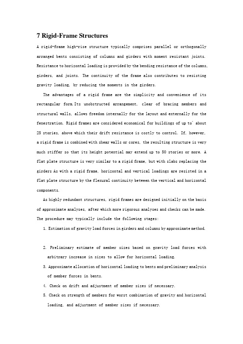
7 Rigid-Frame StructuresA rigid-frame high-rise structure typically comprises parallel or orthogonally arranged bents consisting of columns and girders with moment resistant joints. Resistance to horizontal loading is provided by the bending resistance of the columns, girders, and joints. The continuity of the frame also contributes to resisting gravity loading, by reducing the moments in the girders.The advantages of a rigid frame are the simplicity and convenience of its rectangular form.Its unobstructed arrangement, clear of bracing members and structural walls, allows freedom internally for the layout and externally for the fenestration. Rigid frames are considered economical for buildings of up to' about25 stories, above which their drift resistance is costly to control. If, however,a rigid frame is combined with shear walls or cores, the resulting structure is very much stiffer so that its height potential may extend up to 50 stories or more. A flat plate structure is very similar to a rigid frame, but with slabs replacing the girders As with a rigid frame, horizontal and vertical loadings are resisted in a flat plate structure by the flexural continuity between the vertical and horizontal components.As highly redundant structures, rigid frames are designed initially on the basis of approximate analyses, after which more rigorous analyses and checks can be made. The procedure may typically include the following stages:1. Estimation of gravity load forces in girders and columns by approximate method.2. Preliminary estimate of member sizes based on gravity load forces witharbitrary increase in sizes to allow for horizontal loading.3. Approximate allocation of horizontal loading to bents and preliminary analysisof member forces in bents.4. Check on drift and adjustment of member sizes if necessary.5. Check on strength of members for worst combination of gravity and horizontalloading, and adjustment of member sizes if necessary.6. Computer analysis of total structure for more accurate check on memberstrengths and drift, with further adjustment of sizes where required. This stage may include the second-order P-Delta effects of gravity loading on the member forces and drift..7. Detailed design of members and connections.This chapter considers methods of analysis for the deflections and forces for both gravity and horizontal loading. The methods are included in roughly the order of the design procedure, with approximate methods initially and computer techniques later. Stability analyses of rigid frames are discussed in Chapter 16.7.1 RIGID FRAME BEHAVIORThe horizontal stiffness of a rigid frame is governed mainly by the bending resistance of the girders, the columns, and their connections, and, in a tall frame, by the axial rigidity of the columns. The accumulated horizontal shear above any story of a rigid frame is resisted by shear in the columns of that story (Fig. 7.1). The shear causes the story-height columns to bend in double curvature with points of contraflexure at approximately mid-story-height levels. The moments applied to a joint from the columns above and below are resisted by the attached girders, which also bend in double curvature, with points of contraflexure at approximately mid-span. These deformations of the columns and girders allow racking of the frame and horizontal deflection in each story. The overall deflected shape of a rigid frame structure due to racking has a shear configuration with concavity upwind, a maximum inclination near the base, and a minimum inclination at the top, as shown in Fig.7.1.The overall moment of the external horizontal load is resisted in each story level by the couple resulting from the axial tensile and compressive forces in the columns on opposite sides of the structure (Fig. 7.2). The extension and shortening of the columns cause overall bending and associated horizontal displacements of the structure. Because of the cumulative rotation up the height, the story drift dueto overall bending increases with height, while that due to racking tends to decrease. Consequently the contribution to story drift from overall bending may, in. the uppermost stories, exceed that from racking. The contribution of overall bending to the total drift, however, will usually not exceed 10% of that of racking, except in very tall, slender,, rigid frames. Therefore the overall deflected shape of a high-rise rigid frame usually has a shear configuration.The response of a rigid frame to gravity loading differs from a simply connected frame in the continuous behavior of the girders. Negative moments are induced adjacent to the columns, and positive moments of usually lesser magnitude occur in the mid-span regions. The continuity also causes the maximum girder moments to be sensitive to the pattern of live loading. This must be considered when estimating the worst moment conditions. For example, the gravity load maximum hogging moment adjacent to an edge column occurs when live load acts only on the edge span and alternate other spans, as for A in Fig. 7.3a. The maximum hogging moments adjacent to an interior column are caused, however, when live load acts only on the spans adjacent to the column, as for B in Fig. 7.3b. The maximum mid-span sagging moment occurs when live load acts on the span under consideration, and alternate other spans, as for spans AB and CD in Fig. 7.3a.The dependence of a rigid frame on the moment capacity of the columns for resisting horizontal loading usually causes the columns of a rigid frame to be larger than those of the corresponding fully braced simply connected frame. On the other hand, while girders in braced frames are designed for their mid-span sagging moment, girders in rigid frames are designed for the end-of-span resultant hogging moments, which may be of lesser value. Consequently, girders in a rigid frame may be smaller than in the corresponding braced frame. Such reductions in size allow economy through the lower cost of the girders and possible reductions in story heights. These benefits may be offset, however, by the higher cost of the more complex rigid connections.7.2 APPROXIMATE DETERMINATION OF MEMBER FORCES CAUSED BY GRAVITY LOADSIMGA rigid frame is a highly redundant structure; consequently, an accurate analysis can be made only after the member sizes are assigned. Initially, therefore, member sizes are decided on the basis of approximate forces estimated either by conservative formulas or by simplified methods of analysis that are independent of member properties. Two approaches for estimating girder forces due to gravity loading are given here.7.2.1 Girder Forces—Code Recommended ValuesIn rigid frames with two or more spans in which the longer of any two adjacent spans does not exceed the shorter by more than 20 %, and where the uniformly distributed design live load does not exceed three times the dead load, the girder moment and shears may be estimated from Table 7.1. This summarizes the recommendations given in the Uniform Building Code [7.1]. In other cases a conventional moment distribution or two-cycle moment distribution analysis should be made for a line of girders at a floor level.7.2.2 Two-Cycle Moment Distribution [7.2].This is a concise form of moment distribution for estimating girder moments in a continuous multibay span. It is more accurate than the formulas in Table 7.1, especially for cases of unequal spans and unequal loading in different spans.The following is assumed for the analysis:1. A counterclockwise restraining moment on the end of a girder is positive anda clockwise moment is negative.2. The ends of the columns at the floors above and below the considered girder are fixed.3. In the absence of known member sizes, distribution factors at each joint aretaken equal to 1 /n, where n is the number of members framing into the joint in the plane of the frame.Two-Cycle Moment Distribution—Worked Example. The method is demonstrated by a worked example. In Fig, 7.4, a four-span girder AE from a rigid-frame bent is shown with its loading. The fixed-end moments in each span are calculated for dead loading and total loading using the formulas given in Fig, 7.5. The moments are summarized in Table 7.2.The purpose of the moment distribution is to estimate for each support the maximum girder moments that can occur as a result of dead loading and pattern live loading.A different load combination must be considered for the maximum moment at each support, and a distribution made for each combination.The five distributions are presented separately in Table 7.3, and in a combined form in Table 7.4. Distributions a in Table 7.3 are for the exterior supports A andE. For the maximum hogging moment at A, total loading is applied to span AB with dead loading only on BC. The fixed-end moments are written in rows 1 and 2. In this distribution only .the resulting moment at A is of interest. For the first cycle, joint B is balanced with a correcting moment of- (-867 + 315)/4 = - U/4 assigned to M BA where U is the unbalanced moment. This is not recorded, but half of it, ( - U/4)/2, is carried over to M AB. This is recorded in row 3 and then added to the fixed-end moment and the result recorded in row 4.The second cycle involves the release and balance of joint A. The unbalanced moment of 936 is balanced by adding-U/3 = -936/3 = -312 to M BA (row 5), implicitly adding the same moment to the two column ends at A. This completes the second cycle of the distribution. The resulting maximum moment at A is then given by the addition of rows 4 and 5, 936 - 312 = 624. The distribution for the maximum moment at E follows a similar procedure.Distribution b in Table 7.3 is for the maximum moment at B. The most severe loading pattern for this is with total loading on spans AB and BC and dead load only on CD. The operations are similar to those in Distribution a, except that the T first cycle involves balancing the two adjacent joints A and C while recording only their carryover moments to B. In the second cycle, B is balanced by adding - (-1012 + 782)/4 = 58 to each side of B. The addition of rows 4 and 5 then gives the maximum hogging moments at B. Distributions c and d, for the moments at joints C and D, follow patterns similar to Distribution b.The complete set of operations can be combined as in Table 7.4 by initially recording at each joint the fixed-end moments for both dead and total loading. Then the joint, or joints, adjacent to the one under consideration are balanced for the appropriate combination of loading, and carryover moments assigned .to the considered joint and recorded. The joint is then balanced to complete the distribution for that support.Maximum Mid-Span Moments. The most severe loading condition for a maximum mid-span sagging moment is when the considered span and alternate other spans and total loading. A concise method of obtaining these values may be included in the combined two-cycle distribution, as shown in Table 7.5. Adopting the convention that sagging moments at mid-span are positive, a mid-span total; loading moment is calculated for the fixed-end condition of each span and entered in the mid-span column of row 2. These mid-span moments must now be corrected to allow for rotation of the joints. This is achieved by multiplying the carryover moment, row 3, at the left-hand end of the span by (1 + 0.5 D.F. )/2, and the carryover moment at the right-hand end by -(1 + 0.5 D.F.)/2, where D.F. is the appropriate distribution factor, and recording the results in the middle column. For example, the carryover to the mid-span of AB from A = [(1 + 0.5/3)/2] x 69 = 40 and from B = -[(1+ 0.5/4)/2] x (-145) = 82. These correction moments are then added to the fixed-end mid-span moment to give the maximum mid-span sagging moment, that is, 733 + 40 + 82 = 855.7.2.3 Column ForcesThe gravity load axial force in a column is estimated from the accumulated tributary dead and live floor loading above that level, with reductions in live loading as permitted by the local Code of Practice. The gravity load maximum column moment is estimated by taking the maximum difference of the end moments in the connected girders and allocating it equally between the column ends just above and below the joint. To this should be added any unbalanced moment due to eccentricity of the girderconnections from the centroid of the column, also allocated equally between the column ends above and below the joint.第七章框架结构高层框架结构一般由平行或正交布置的梁柱结构组成,梁柱结构是由带有能承担弯矩作用节点的梁、柱组成。
推荐-土木工程专业 外文文献翻译 高层框架剪力墙结构设计 精品
(本科外文文献翻译学校代码: 10128学 号:题 目:Shear wall structural design of high-level framework 学生姓名: 学 院:土木工程学院 系 别:建筑工程系 专 业:土木工程专业(建筑工程方向) 班 级:土木08-(5)班 指导教师:Shear wall structural design of high-level frameworkWu JichengAbstract: In this paper the basic concepts of manpower from the frame shear wall structure, analysis of the structural design of the content of the frame shear wall, including the seismic wall shear span ratio design, and a concrete structure in the most monly used frame shear wall structure the design of points to note.Keywords: concrete; frame shear wall structure; high-rise buildings The wall is a modern high-rise buildings is an important building content, the size of the frame shear wall must ply with building regulations. The principle is that the larger size but the thickness must be smaller geometric features should be presented to the plate, the force is close to cylindrical. The wall shear wall structure is a flat ponent. Its exposure to the force along the plane level of the role of shear and moment, must also take into account the vertical pressure. Operate under the bined action of bending moments and axial force and shear force by the cantilever deep beam under the action of the force level to look into the bottom mounted on the basis of. Shear wall is divided into a whole wall and the associated shear wall in the actual project, a whole wall for example, such as general housing construction in the gable or fish bone structure film walls and small openings wall. Coupled Shear walls are connected by the coupling beam shear wall. But because the generalcoupling beam stiffness is less than the wall stiffness of the limbs, so. Wall limb alone is obvious. The central beam of the inflection point to pay attention to the wall pressure than the limits of the limb axis. Will form a short wide beams, wide column wall limb shear wall openings too large ponent at both ends with just the domain of variable cross-section rod in the internal forces under the action of many Wall limb inflection point Therefore, the calculations and construction shouldAccording to approximate the frame structure to consider. The design of shear walls should be based on the characteristics of a variety of wall itself, and different mechanical characteristics and requirements, wall of the internal force distribution and failure modes of specific and prehensive consideration of the design reinforcement and structural measures. Frame shear wall structure design is to consider the structure of the overall analysis for both directions of the horizontal and vertical effects. Obtain the internal force is required in accordance with the bias or partial pull normal section force calculation. The wall structure of the frame shear wall structural design of the content frame high-rise buildings, in the actual project in the use of the most seismic walls have sufficient quantities to meet the limits of the layer displacement, the location is relatively flexible. Seismic wall for continuous layout, full-length through. Should be designed to avoid the wall mutations in limb length and alignment is not up and down the hole. The same time. The inside of thehole margins column should not be less than 300mm in order to guarantee the length of the column as the edge of the ponent and constraint edge ponents. The bi-directional lateral force resisting structural form of vertical and horizontal wall connected. Each other as the affinity of the shear wall. For one, two seismic frame shear walls, even beam high ratio should not greater than 5 and a height of not less than 400mm. Midline column and beams, wall midline should not be greater than the column width of 1/4, in order to reduce the torsional effect of the seismic action on the column. Otherwise can be taken to strengthen the stirrup ratio in the column to make up. If the shear wall shear span than the big two. Even the beam cross-height ratio greater than 2.5, then the design pressure of the cut should not make a big 0.2. However, if the shear wall shear span ratio of less than two coupling beams span of less than 2.5, then the shear pression ratio is not greater than 0.15. The other hand, the bottom of the frame shear wall structure to enhance the design should not be less than 200mm and not less than storey 1/16, other parts should not be less than 160mm and not less than storey 1/20. Around the wall of the frame shear wall structure should be set to the beam or dark beam and the side column to form a border. Horizontal distribution of shear walls can from the shear effect, this design when building higher longer or frame structure reinforcement should be appropriately increased, especially in the sensitive parts of the beam position or temperature, stiffness change isbest appropriately increased, then consideration should be given to the wall vertical reinforcement, because it is mainly from the bending effect, and take in some multi-storey shear wall structure reinforced reinforcement rate - like less constrained edge of the ponent or ponents reinforcement of the edge ponent.References: [1 sad Hayashi, He Yaming. On the short shear wall high-rise building design [J].Keyuan, 20XX, (O2).高层框架剪力墙结构设计摘要: 本文从框架剪力墙结构设计的基本概念人手,分析了框架剪力墙的构造设计内容,包括抗震墙、剪跨比等的设计,并出混凝土结构中最常用的框架剪力墙结构设计的注意要点。
毕业论文外文文献翻译-高层建筑

外文翻译题目:高层建筑学院土木建筑工程学院专业土木工程(建筑工程方向)班级学号姓名指导教师Tall BuildingsAlthough there have been many advancements in building construction technology in general, spectacular achievements have been made in the design and construction of ultrahigh-rise buildings.The early development of high-rise buildings began with structural steel framing. Reinforced concrete and stressed-skin tube systems have since been economically and competitively used in a number of structures for both residential and commercial purposes. The high-rise buildings ranging from 50 to 110 stories that are being built all over the United States are the result of innovations and development of new structural systems.Greater height entails increased column and beam sizes to make buildings more rigid so that under wind load they will not sway beyond an acceptable limit. Excessive lateral sway may cause serious recurring damage to partitions, ceilings, and other architectural details. In addition, excessive sway may cause discomfort to the occupants of the building because of their perception of such motion. Structural systems of reinforced concrete, as well as steel, take full advantage of the inherent potential stiffness of the total building and therefore do not require additional stiffening to limit the sway.In a steel structure, for example, the economy can be defined in terms of the total average quantity of steel per square foot of floor area of the building. Curve A in Fig. 1 represents the average unit weight of a conventional frame with increasing numbers of stories. Curve B represents the average steel weight if the frame is protected from all lateral loads. The gap between the upper boundary and the lower boundary represents the premium for height for the traditional column-and-beam frame; Structural engineers have developed structural systems with a view to eliminating this premium.Systems in steel. Tall buildings in steel developed as a result of several types of structural innovations. The innovations have been applied to the construction of both office and apartment buildings.Frames with rigid belt trusses. In order to tie the exterior columns of a frame structure to the interior vertical trusses, a system of rigid belt trusses at mid-height and at the top of the building may be used. A good example of this system is the First Wisconsin Bank Building (1974) in Milwaukee.Framed tube. The maximum efficiency of the total structure of a tall building, for bothstrength and stiffness, to resist wind load can be achieved only if all column elements can be connected to each other in such a way that the entire building acts as a hollow tube or rigid box in projecting out of the ground. This particular structural system was probably used for the first time in the 43-story reinforced concrete DeWitt Chestnut Apartment Building in Chicago. The most significant use of this system is in the twin structural steel towers of the 110-story World Trade Center building in New York.Column-diagonal truss tube. The exterior columns of a building can be spaced reasonably far apart and yet be made to work together as a tube by connecting them with. Diagonal members intersecting at the center line of the columns and beams. This simple yet extremely efficient system was used for the first time on the John Hancock Center in Chicago, using as much steel as is normally needed for a traditional story building.Fig. 1. Graphical relationship between design quantities of steel and building heights for a typical building frame. Curves A and B correspond to the boundary conditions indicated in the two building diagrams. 1 psf = 0. 048kPa.Bundled tube. With the continuing need for larger and taller buildings, the framed tube or the column-diagonal truss tube may be used in a bundled form to create larger tube envelopes while maintaining high efficiency. The i10-story Sears Roebuck Headquarters Building in Chicago has nine tubes, bundled at tile base of the building in three rows. Some of these individual tubes terminate at different heights of the building, demonstrating the unlimited architectural possibilities of this latest structural concept. The Sears tower, at a height of 1450 ft (442 m), is the world's tallest building.Stressed-skin tube system. The tube structural system was developed for improving the resistance to lateral forces (wind or earthquake) and the control of drift (lateral building movement) in high-rise building. The stressed-skin tube takes the tube system a step further. The development of the stressed-skin tube utilizes the facade of the building as a structural element which acts with the framed tube, thus providing an efficient way of resisting lateral loads in high-rise buildings, and resulting in cost-effective column-free interior space with a high ratio of net to gross floor area.Because of the contribution of the stressed-skin facade, the framed members of the tube require less mass, and are thus lighter and less expensive. All the typical columns and spandrel beams are standard rolled shapes, minimizing the use and cost of special built-up members. The depth requirement for the perimeter spandrel beams is also reduced, and the need for upset beams above floors, which would encroach on valuable space, is minimized. The structural system has been used on the 54-story One Mellon Bank Center in Pittsburgh.Systems in concrete. While tall buildings constructed of steel had an early start, development of tall buildings of reinforced concrete progressed at a fast enough rate to provide a competitive challenge to structural steel systems for both office and apartment buildings.Framed tube. As discussed above, the first framed tube concept for tall buildings was used for the 43-story DeWitt Chestnut Apartment Building. In this building, exterior columns were spaced at 5.5-ft (1.68-m) centers, and interior columns were used as needed to support the 8-in.-thick (20-cm) flat-plate concrete slabs.Tube in tube. Another system in reinforced concrete for office buildings combines the traditional shear wall construction with an exterior framed tube. The system consists of an outer framed tube of very closely spaced columns and an interior rigid shear wall tube enclosing the central service area. The system (Fig.2), known as the tube-in-tube system, made it possible to design the world's present tallest (714 ft or 218m) lightweight concrete Building in Houston)for structure of only 35 s oriel building the unit 52—story One Shell Plaza of a traditional shear wallSystems compiling both concrete and steel have also been developed,an example of which is the composite system developed by Skidmore,Owings & Merrill in which an exterior closely spaced framed tube in concrete envelops an interior steel framing,thereby combining the advantages of both reinforced concrete and structuralsteel systems.The 52—story One Shell Square Building in New Orleans is based on this system.NEW WORDS AND PHRASES1.spectacular 壮观的,惊人的,引人注意的2.sway 摇动,摇摆,歪,使倾斜3.residential 居住的,住宅的,作住家用的4.commercial 商业的,商业上的,商务的5.innovation 革新,创新,新方法,新事物6.boundary 分界线,边界7.eliminate 排除,消除,除去8.apartment 公寓住宅,单元住宅9.column 柱,支柱,圆柱,柱状物10.demonstrate 示范,证明,演示,11.project 凸出,投射,计划,工程12.stress 应力,压力13.truss 构架,桁架14.bundle 捆,束,包15.terminate 使终止,使结尾,结束16.facade (房屋的)/E面,立面,表面17.perimeter 周,周围,周界,周长18.encroach 侵犯,侵占,蚕食19.high·rise building 高层建筑20.reinforced concrete 钢筋混凝土21.spandrel beam 窗下墙的墙托梁22.shear wall 剪力墙高层建筑大体上建筑施工工艺学方面已经有许多进步, 在超高层的设计和施工上已经取得了惊人的成就。
建筑设计中英文对照

●房屋各部分Partsofhouse屋面roof屋脊ridge坡屋顶pitchedroof单坡屋顶pentroof,lean-toroof 人字屋顶gableroof四坡顶hippedroof屋面排水沟valley卷材防水屋面membraneroof找平层screed-coat防水层damp-proofcourse泛水flashing屋顶层garret阁楼penthouse,loft,attic天台roof-deck晒台dryingstage组合烟囱chimneystack屋檐eave屋面排水roofingdrainage檐沟,明沟gutter水落管down-pipe,downspout雨棚canopy,awning柱廊colonnade走廊corridor中庭atrium山墙gable女儿墙parapet山花pediment隅石砌quoins阳台balcony,veranda阳台栏杆balustrade阳台栏杆柱baluster,banister平台terrace台阶steps梯子ladder梯级step楼梯staircase(=step)楼梯踏步平板tread楼梯踏步竖板riser楼梯休息平台landing直角转弯平台quarter-spacelanding梯宽runofstair梯高riseofstair楼梯扶手rail,railing回转梯corkscrewstaircase,caracole 踏步突沿nosing窗子window百叶窗blinds,louvers旋转窗balancewindow平开窗,窗叶casement中旋窗awningwindow上下推拉窗double-hungwindow屋顶通气窗clerestory门窗亮子transom窗框windowframe窗台sill,cill采光顶sunroof天窗sunlight老虎窗dormer-window通风窗ventlight落地窗Frenchwindow墙壁wall承重墙bearingwall隔间partition空心墙cavitywall防火隔断(分区)compartmentation 剪力墙shearpanel墙裙wainscot窗间墙pier幕墙curtainwall电梯elevator,lift自动扶梯escalator地板,楼面floor夹层楼面entresol,mezzanine楼座balcony天花板ceiling壁炉andiron,fireplace,grate 地下室basement防火fire-cut防火门firedoor耐热涂料heat-resistingpaints 绝热heatinsulation门槛head-rail,sill柱子column,post,pillar柱头columncap,head斜撑kneebrace悬索catenary梁beam基础梁gradebeam钢板梁plategirder工字梁I-beam过梁lintel,lintol,head椽子purlin基础foundation碎石垫层hardcore混凝土地基concretefoundation 基座、柱础pedestal独立基础isolatedfooting放大基础spreadingfooting条形基础stripfooting浮筏基础floatingfoundation 沉箱基础caisson化粪池cesspool,septictank 伸缩缝expansionjoint冷桥thermalbridge散水wash,apron披水板weathering-board桁架truss组合桁架compositetruss框架framework模板formwork拱券arch穹顶dome平拱flatarch筒拱vault,vaultedroof半圆穹顶concha瓦shingle,tile砖brick瓷砖ceramictile玻璃砖glassblocks大理石marble花岗岩granite水磨石terrazzo砌块masonry混凝土concrete钢筋混凝土reinforcedconcrete钢筋steelreinforcement水泥cement抹灰,灰泥plaster,stucco熟石灰hydrateoflime,slaked-lime 砂浆mortar抹灰层floatedcoat饰面finish木砖grounds,timberbrick石膏gypsum石膏板plasterslab夹胶玻璃plyglass胶合板plywood,clip-board脚手架scaffolding悬臂cantilever叠涩,牛腿corbel遮阳sunshading●制图与构图用语草图sketch,draft图纸drawing施工图workingdrawings工程project方案plan总图grid总平面site立面elevation正立面facade剖面section详图detail门厅上部upperfoyer比例尺scale=透视图,表现图rendering透视perspective轴测isometricperspectiveAxonometricprojection轴线axis建筑面积floorarea,architecturearea 相对标高relativeelevation/level层高,净空headroom,headway室内interior室外exterior室内装修interiordecoration装饰ornament广场square,plaza,publicsquare流线circulation解构deconstruction空间space,spatial比例proportion统一unity均衡balance尺度scale韵律rhythm风格style功能function关系relationship●房屋House高层建筑high-risebuilding社区housingcomplex家舍house茅舍cottage平房one-storyhouse,bungalow,plain-house二楼two-storyhouse公寓(建筑)apartmenthouse公寓(房间)apartment(flat)(英)别墅villa花园洋房gardenhouse寄宿舍dormitory(美)供膳出租房间boardandlodging出租房间roomforrent(美)乡村旅舍countryinn供膳寄宿舍boardinghouse大厦mansions,edifice大楼building预制装配式房屋pre-fabricatehouse一个单元oneunit车库garage报告厅auditorium,lecturehall多功能厅multi-usehall阅览室browsingroom,readingroom茶室refreshmentroom操作间cab,utilityroom●居住Dwelling套房suit主人套房mastersuit门厅,前厅lobby大厅hall,mainhall过厅gallery起居间livingRM,familyRM聚会厅gatheringRM,keepingRM休息厅lounge,sittingRM客厅parlor衣帽间cloakroom更衣、衣橱间walk-in-closet,W.I.C. 厨房kitchen餐厅dinningroom早餐厅nook,breakfastroom食品、餐具间pantry,butlery浴室,洗手间bathroom盥洗室toiletroom前室,门厅foyer寝室,卧房bedroom主人房masterbedroom书斋,书房study,library工作室,画室studio私室,书斋den化妆室boudoir,dressingRM,powderRM 婴儿室nursery客房guestroom壁厨closet,ambry洗衣间laundryroom地窖cellar储藏室storage健身房exerciseRM服务入口serviceentry换鞋处mudroom游艺室gamesroom活动室activitiesroom音乐室musicalcove工人房maidbedroom台球室billiardsroom温室greenhouse●家具Furniture方桌squaretable圆桌roundtableWORD格式伸缩桌extensiontable小桌sidetable凳子stool有肘的椅子armchair摇椅,安乐椅rockingchair藤椅rattanchair塑料椅plasticchair帆布椅deckchair折椅foldingchair沙发sofa长椅couch桌子,餐桌table玻璃桌子glasstable塑料桌子acrylictable木制饭桌wooden-tableZ专业资料整理。
高层建筑设计中英文对照外文翻译文献
中英文对照外文翻译文献(文档含英文原文和中文翻译)Structural Systems to resist lateral loadsmonly Used structural SystemsWith loads measured in tens of thousands kips, there is little room in the design of high-rise buildings for excessively complex thoughts. Indeed, the better high-rise buildings carry the universal traits of simplicity of thought and clarity of expression.It does not follow that there is no room for grand thoughts. Indeed, it is with such grand thoughts that the new family of high-rise buildings has evolved. Perhaps more important, the new concepts of but a few years ago have become commonplace in today’ s technology.Omitting some concepts that are related strictly to the materials of construction, the most commonly used structural systems used in high-rise buildings can be categorized as follows:1.Moment-resisting frames.2.Braced frames, including eccentrically braced frames.3.Shear walls, including steel plate shear walls.4.Tube-in-tube structures.5.Tube-in-tube structures.6.Core-interactive structures.7.Cellular or bundled-tube systems.Particularly with the recent trend toward more complex forms, but in response also to the need for increased stiffness to resist the forces from wind and earthquake, most high-rise buildings have structural systems built up of combinations of frames, braced bents, shear walls, and related systems. Further, for the taller buildings, the majorities are composed of interactive elements in three-dimensional arrays.The method of combining these elements is the very essence of the design process for high-rise buildings. These combinations need evolve in response to environmental, functional, and cost considerations so as to provide efficient structures that provoke the architectural development to new heights. This is not to say that imaginative structural design can create great architecture. To the contrary, many examples of fine architecture have been created with only moderate support from the structural engineer, while only fine structure, not great architecture, can be developed without the genius and the leadership of a talented architect. In any event, the best of both is needed to formulate a truly extraordinary design of a high-rise building.While comprehensive discussions of these seven systems are generally available in the literature, further discussion is warranted here .The essence of the design process is distributed throughout the discussion.2.Moment-Resisting FramesPerhaps the most commonly used system in low-to medium-rise buildings, the moment-resisting frame, is characterized by linear horizontal and vertical members connected essentially rigidly at their joints. Such frames are used as a stand-alone system or in combination with other systems so as to provide the needed resistance to horizontal loads. In the taller of high-rise buildings, the system is likely to be found inappropriate for a stand-alone system, this because of the difficulty in mobilizing sufficient stiffness under lateral forces.Analysis can be accomplished by STRESS, STRUDL, or a host of other appropriatecomputer programs; analysis by the so-called portal method of the cantilever method has no place in today’s technology.Because of the intrinsic flexibility of the column/girder intersection, and because preliminary designs should aim to highlight weaknesses of systems, it is not unusual to use center-to-center dimensions for the frame in the preliminary analysis. Of course, in the latter phases of design, a realistic appraisal in-joint deformation is essential.3.Braced FramesThe braced frame, intrinsically stiffer than the moment –resisting frame, finds also greater application to higher-rise buildings. The system is characterized by linear horizontal, vertical, and diagonal members, connected simply or rigidly at their joints. It is used commonly in conjunction with other systems for taller buildings and as a stand-alone system in low-to medium-rise buildings.While the use of structural steel in braced frames is common, concrete frames are more likely to be of the larger-scale variety.Of special interest in areas of high seismicity is the use of the eccentric braced frame.Again, analysis can be by STRESS, STRUDL, or any one of a series of two –or three dimensional analysis computer programs. And again, center-to-center dimensions are used commonly in the preliminary analysis.4.Shear wallsThe shear wall is yet another step forward along a progression of ever-stiffer structural systems. The system is characterized by relatively thin, generally (but not always) concrete elements that provide both structural strength and separation between building functions.In high-rise buildings, shear wall systems tend to have a relatively high aspect ratio, that is, their height tends to be large compared to their width. Lacking tension in the foundation system, any structural element is limited in its ability to resist overturning moment by the width of the system and by the gravity load supported by the element. Limited to a narrow overturning, One obvious use of the system, which does have the needed width, is in the exterior walls of building, where the requirement for windows is kept small.Structural steel shear walls, generally stiffened against buckling by a concrete overlay, have found application where shear loads are high. The system, intrinsically more economicalthan steel bracing, is particularly effective in carrying shear loads down through the taller floors in the areas immediately above grade. The sys tem has the further advantage of having high ductility a feature of particular importance in areas of high seismicity.The analysis of shear wall systems is made complex because of the inevitable presence of large openings through these walls. Preliminary analysis can be by truss-analogy, by the finite element method, or by making use of a proprietary computer program designed to consider the interaction, or coupling, of shear walls.5.Framed or Braced TubesThe concept of the framed or braced or braced tube erupted into the technology with the IBM Building in Pittsburgh, but was followed immediately with the twin 110-story towers of the World Trade Center, New York and a number of other buildings .The system is characterized by three –dimensional frames, braced frames, or shear walls, forming a closed surface more or less cylindrical in nature, but of nearly any plan configuration. Because those columns that resist lateral forces are placed as far as possible from the cancroids of the system, the overall moment of inertia is increased and stiffness is very high.The analysis of tubular structures is done using three-dimensional concepts, or by two- dimensional analogy, where possible, whichever method is used, it must be capable of accounting for the effects of shear lag.The presence of shear lag, detected first in aircraft structures, is a serious limitation in the stiffness of framed tubes. The concept has limited recent applications of framed tubes to the shear of 60 stories. Designers have developed various techniques for reducing the effects of shear lag, most noticeably the use of belt trusses. This system finds application in buildings perhaps 40stories and higher. However, except for possible aesthetic considerations, belt trusses interfere with nearly every building function associated with the outside wall; the trusses are placed often at mechanical floors, mush to the disapproval of the designers of the mechanical systems. Nevertheless, as a cost-effective structural system, the belt truss works well and will likely find continued approval from designers. Numerous studies have sought to optimize the location of these trusses, with the optimum location very dependent on the number of trusses provided. Experience would indicate, however, that the location of these trusses is provided by the optimization of mechanical systems and by aesthetic considerations,as the economics of the structural system is not highly sensitive to belt truss location.6.Tube-in-Tube StructuresThe tubular framing system mobilizes every column in the exterior wall in resisting over-turning and shearing forces. The term‘tube-in-tube’is largely self-explanatory in that a second ring of columns, the ring surrounding the central service core of the building, is used as an inner framed or braced tube. The purpose of the second tube is to increase resistance to over turning and to increase lateral stiffness. The tubes need not be of the same character; that is, one tube could be framed, while the other could be braced.In considering this system, is important to understand clearly the difference between the shear and the flexural components of deflection, the terms being taken from beam analogy. In a framed tube, the shear component of deflection is associated with the bending deformation of columns and girders (i.e, the webs of the framed tube) while the flexural component is associated with the axial shortening and lengthening of columns (i.e, the flanges of the framed tube). In a braced tube, the shear component of deflection is associated with the axial deformation of diagonals while the flexural component of deflection is associated with the axial shortening and lengthening of columns.Following beam analogy, if plane surfaces remain plane (i.e, the floor slabs),then axial stresses in the columns of the outer tube, being farther form the neutral axis, will be substantially larger than the axial stresses in the inner tube. However, in the tube-in-tube design, when optimized, the axial stresses in the inner ring of columns may be as high, or even higher, than the axial stresses in the outer ring. This seeming anomaly is associated with differences in the shearing component of stiffness between the two systems. This is easiest to under-stand where the inner tube is conceived as a braced (i.e, shear-stiff) tube while the outer tube is conceived as a framed (i.e, shear-flexible) tube.7.Core Interactive StructuresCore interactive structures are a special case of a tube-in-tube wherein the two tubes are coupled together with some form of three-dimensional space frame. Indeed, the system is used often wherein the shear stiffness of the outer tube is zero. The United States Steel Building, Pittsburgh, illustrates the system very well. Here, the inner tube is a braced frame, the outer tube has no shear stiffness, and the two systems are coupled if they were considered as systemspassing in a straight line from the “hat” structure. Note that the exterior columns would be improperly modeled if they were considered as systems passing in a straight line from the “hat” to the foundations; these columns are perhaps 15% stiffer as they follow the elastic curve of the braced core. Note also that the axial forces associated with the lateral forces in the inner columns change from tension to compression over the height of the tube, with the inflection point at about 5/8 of the height of the tube. The outer columns, of course, carry the same axial force under lateral load for the full height of the columns because the columns because the shear stiffness of the system is close to zero.The space structures of outrigger girders or trusses, that connect the inner tube to the outer tube, are located often at several levels in the building. The AT&T headquarters is an example of an astonishing array of interactive elements:1.The structural system is 94 ft (28.6m) wide, 196ft(59.7m) long, and 601ft (183.3m)high.2.Two inner tubes are provided, each 31ft(9.4m) by 40 ft (12.2m), centered 90 ft (27.4m)apart in the long direction of the building.3.The inner tubes are braced in the short direction, but with zero shear stiffness in the longdirection.4. A single outer tube is supplied, which encircles the building perimeter.5.The outer tube is a moment-resisting frame, but with zero shear stiffness for thecenter50ft (15.2m) of each of the long sides.6. A space-truss hat structure is provided at the top of the building.7. A similar space truss is located near the bottom of the building8.The entire assembly is laterally supported at the base on twin steel-plate tubes, becausethe shear stiffness of the outer tube goes to zero at the base of the building.8.Cellular structuresA classic example of a cellular structure is the Sears Tower, Chicago, a bundled tube structure of nine separate tubes. While the Sears Tower contains nine nearly identical tubes, the basic structural system has special application for buildings of irregular shape, as the several tubes need not be similar in plan shape, It is not uncommon that some of the individual tubes one of the strengths and one of the weaknesses of the system.This special weakness of this system, particularly in framed tubes, has to do with the concept of differential column shortening. The shortening of a column under load is given by the expression△=ΣfL/EFor buildings of 12 ft (3.66m) floor-to-floor distances and an average compressive stress of 15 ksi (138MPa), the shortening of a column under load is 15 (12)(12)/29,000 or 0.074in (1.9mm) per story. At 50 stories, the column will have shortened to 3.7 in. (94mm) less than its unstressed length. Where one cell of a bundled tube system is, say, 50stories high and an adjacent cell is, say, 100stories high, those columns near the boundary between .the two systems need to have this differential deflection reconciled.Major structural work has been found to be needed at such locations. In at least one building, the Rialto Project, Melbourne, the structural engineer found it necessary to vertically pre-stress the lower height columns so as to reconcile the differential deflections of columns in close proximity with the post-tensioning of the shorter column simulating the weight to be added on to adjacent, higher columns.抗侧向荷载的结构体系1.常用的结构体系若已测出荷载量达数千万磅重,那么在高层建筑设计中就没有多少可以进行极其复杂的构思余地了。
建筑专业部分相关英语词汇
建筑专业部分相关英语词汇建筑类型类民用建筑civil architecture工业建筑industrial building居住区residential area坡地住宅stepped hillside house联排住宅terraced house错层式住宅split-level house半独立式住宅semi-detached house 公寓apartment, flat多层建筑multi-storey block高层建筑high-rise block商业建筑business premises乡土建筑vernacular architecture本土建筑,地域建筑local architecture 绿色建筑green architecture基础设施infrastructure设计过程类可行性研究feasibility study进度表time schedule方案草图preliminary sketch初步设计preliminary design施工设计final design详图设计detail design图纸drawing平面图plan立面图elevation东立面图east elevation南立面图south elevation西立面图west elevation北立面图north elevation横剖面cross section纵剖面longitudinal section轴测图isometric view鸟瞰图bird’s-eye view施工图working drawing总体规划图master plan 索引图key, key plan现场质量管理site supervision工程质量管理project supervision验收final approval建筑指标类层高story height居住面积living area建筑占地面积covered area容积率plot ratio覆盖率coverage绿地率ratio of green space人口密度population density居住密度density of settlement建筑元素类走廊corridor, passage挑廊overhanging corridor檐廊eaves corridor回廊cloister凉廊loggia过街楼arcade门斗foyer阁楼attic阳台balcony雨篷canopy自然层floor维护结构envelop enclosure围护性幕墙enclosing curtain wall装饰性幕墙decorative faced curtain wall 落地窗French window百叶窗shutter, louver window起居室living room餐室dining room厨房kitchen浴室bathroom淋浴shower单人卧室single bedroom双人卧室double bedroom备餐室pantry洗衣间laundry贮藏室store room地下室basement半地下室semi-basement永久性顶盖permanent cap螺旋楼梯spiral staircase建筑结构类梁beam, girder圈梁ring beam简支梁suspended beam悬臂梁cantilever beam固端梁fixed-end beam连续梁continuous beam拱arch板slab, plate简支板suspended slab嵌固板fixed-edge slab单向板one-way slab双向板two-way slab肋形板ribbed slab井字形梁板groined slab壳shell柱column墙wall承重墙load bearing wall桁架truss框架framework排架bent frame刚架(刚构)rigid frame桩pile板桩sheet pile结构structure基础foundation地基foundation soil, subgrade, subbase 木结构timber structure拱结构arch structure钢结构steel structure砌体结构masonry structure混凝土(砼)结构concrete structure混合结构mixed structure板柱结构slab-column system 框架结构frame structure折板结构folded-plate structure壳体结构shell structure悬索结构cable-suspended structure充气结构pneumatic structure拉膜结构tensile structure剪力墙(结构墙)结构shear wall structure框架-剪力墙结构frame-shear wall structure筒体结构tube structure悬挂结构suspended structure扩展(扩大)基础spread foundation刚性基础rigid foundation独立基础single footing联合基础combined footing条形基础strip foundation壳体基础shell foundation箱形基础box foundation筏形基础raft foundation桩基础pile foundation沉箱基础caisson foundation管柱基础cylinder pile foundation, cylinder caisson foundation基床bed, bedding建筑构造类壁纸wall paper墙面砖wall tile地面砖floor tile勒脚,柱础plinth踢脚skirting木踢脚timber skirting榫槽,地槽groove墙槽wall conduit墙基wall footing踢脚skirting凹圆踢脚coved skirting凹形线脚sunk moulding凹缝open joint平缝butt joint伸缩缝expansion and contraction joint沉降缝settlement joint防震缝aseismic joint变形缝deformation joint施工缝construction joint防潮层moisture barrier隔热保温层heat insulation防水water proofing防湿moisture proofing防潮damp proofing隔声sound proofing外墙external wall内墙internal wall隔墙partition wall女儿墙parapet wall踏面tread踢面riser防滑条reeding栏杆railing扶手handrail排水沟drainage ditch护坡slope protection, revetment挡土墙retaining wall建筑材料类钢筋混凝土reinforced concrete现浇混凝土cast-in-situ concrete预制混凝土precast concrete预应力混凝土prestressed concrete 加气混凝土aerated concrete碎石混凝土rubble concrete清水混凝土exposed concrete水泥cement石灰lime水泥砂浆cement mortar石灰砂浆lime mortar石膏gypsum熟石膏plaster of Paris砂sand砾石gravel砖brick空心砌块hollow block混凝土砌块concrete block木材timber瓦roofing tile 屋面毡roofing felt钢筋reinforcing steel涂料paint景观设计类广场square水景water feature圆形剧场,露天剧场amphitheatre儿童乐园children’s playground羽毛球场badminton court篮球场basketball court网球场tennis court停车场parking area屋顶花园roof garden, green roof凉亭pavilion花架pergola (比较:宝塔pagoda)行车道carriageway人行道sidewalk自行车道bicycle path国外建筑类多立克柱Doric column爱奥尼亚柱Ionic column科林斯柱Corinthian column古典主义的classical新古典主义的neoclassical拜占庭Byzantine文艺复兴renaissance帕拉迪奥母题Palladian motive巴洛克baroque洛可可rococo哥特式gothic罗马风Romanesque新艺术运动art nouveau现代主义运动modern movement现代主义modernism后现代主义post-modernism解构主义deconstructionism邻里单位neighbourhood unit田园城市garden city。
高层建筑剪力墙结构中英文对照外文翻译文献
中英文资料翻译一.英文原文A NEW STAGGERED SHEAR WALL STRUCTURE FOR HIGH-RISE BUILDINGABSTRACTShear wall structure has been widely used in tall buildings. However, there are still two obvious disadvantages in this structure: first of all, space between two shear wall could not too big and the plane layout is not flexible, so that serviceability requirements are dissatisfied for public buildings; secondly, the bigger dead weight will lead to the increase of constructional materials and seismic force which cause desigh difficulty of super-structures and foundations. In this paper, a new type tall building structure-staggered shear wall structure-is presented in order to overcome above disadvantages of traditional shear wall, which not only provide big space for architectural design but also has lighter dead weight and high capacity of resistance to horizontal load. REINFORCEMENT CONCRETE STAGGERED SHEAR WALL STRUCTURAL SYSTEM IN TALL BUILDINGS Structure Style and Features of New Type Shear Wall Structural System:In this new-type shear wall structural system,every shear wall is at staggered location on adjacent floor, as well as adjacent shear walls are staggered with each other.One end of floor slab is supported on top edge of one shear wall; the other end of floor slab is supported on bottom edge of adjacent shear wall. The edge column and beam are set beside every shear wall. The embedded column and connected beam are set on every floor. The advantage of this structural system is its big use space with small span floor slab.The shear wall arrangement can be staggered or not according to use requirement, shown in Figure 1. As a result, the width of one bay is increased from L to 2L or 3L. In addition, the dead weigh of staggered shear wall is smaller than that of traditional down-to-ground shear wall, so the material cost is reduced. The structural analysis result indicates the wall amount decreases by 25% and the dead weigh decreased by 20%comparing the new-type shear wall with traditional shear wall, while both have same lateral stiffness. Two main obvious disadvantages of traditional shear wall are overcome and the use space of shear wall structures is enlarged effectively. Besides the architectural convenience, the staggered shear wall has other advantages. Although the stiffness of every shear wall is changed along vertical direction, the sum stiffness of whole structure is even along vertical direction when adjacent shear walls are set on staggered locations. The whole structural deformation is basically bending style. Form the analysis of reference,the staggered shear wall has stronger whole stiffness, less top-storey displacement(decreasing by about 58%),and less relative storey displacement comparing with traditional coupled shear wall.Under the same horizontal load, the staggered shear wall structure could effectively cut down the internal force of coupled beam and embedded column, at the same time the structural seismic performance is improved.1 2Working Mechanism of New Type Shear Wall StructureUnder the vertical load, this structure effect is the same as ordinary frame-shear wall structure, that is, the shear wall and column act together to resist the vertical load. Because the stiffness of every span shear wall is large and the deformation is small, the bending deformation and moment of columns are very small. Under lateral load, the structure deformation is uniform, thereby it can improve the whole stiffness effectively and the higher capability resisting lateral load is obtained.The main cause is the particular arrangement method of walls, which could be explained as follows: firstly, the lateralshearing force transfer mechanism is different from traditional shear wall. The lateral shearing force on top edge of shear wall is transferred to under layer floor slab though the bottom edge of wall, then to under storey adjacent shear wall through the under storey floor slab. At last, the lateral shearing force is transferred to ground floor shear wall and foundation.By this way,the lateral shearing force transfer mechanism is special, in which every floor slab transfer the lateral shearing force of itself floor and above floor.But in traditional shear wall directly. This structure makes the best use of the peculiarity that the slab stiffness is very strong to transfer and resist lateral shear. Although the shear walls are not up bottom in sequence, the slabs which has larger stiffness participate in the work transferring and resisting lateral shear force from the top to the down,from the floor middle part to edge, and from the edge to middle part in whole structure.It corresponds to a space integer structure with large lateral stiffness connected all shear walls by slabs, which have been cut in every story and span. It has been proved in author’s paper that the whole structure will occur integer-bending deformation under lateral force action,while every storey shear walls will occur integer bending without local bending. Secondly, in every piece of staggered shear wall (shown in Figure 2),the shear wall arrangement forms four large X diagonal brace along adcb,cfed, ehgf, gjih (dashed as shown in Figure 2).Because the shear walls forming X diagonal brace have large stiffness and strength, the X diagonal brace stiffness is strong. In addition, both the edge beams and columns around the boundary form bracing ‘frame”with large lateral stiffness. Hence, the structural integer stiffness is greatly improved.Due to the above main reasons, this structure is considered to have particular advantages compared with traditional shear wall structure in improving structural lateral stiffness. It can provide larger using space, and reduce the material, earthquake action as well as dead weight.Also, it can provide larger lateral stiffness, which will benefit the structural lateral capability. In author’s paper and in this paper the example calculating results indicates that lateral stiffness of this structure are double of coupled shear wall structure ,and nearly equal to integer shear wall structure (light small than the latter).Aseismic analysis and construction measures in a buildingexampleIn order to study dynamic characteristics and aseismic performances in this structural system, the staggered shear wall will be used as all cross walls in the large bay shear wall structure without internal longitudinal walls.Example. Thereis a nine-storey reinforcement concrete building, which is large bay shear wall struvture, shown in figure3. here,walls columns, beams, and slabs are all cast-in-situ. The thickness t=240mm is used for shear walls from 1 to 3 stories, while thickness t=200mm is used for shear walls from 4 to 9 stories. Given the section of columns of width b=500mm and depth h=600mm . Given the section of beams of width b=300mm and depth h=700mm . The modulus of elasticity is assumed to be E=2.1*10E7kN/2m and G=1.05*10E7 kN /2m . The external longitudinal walls are cast-in-situ wall frame, and the cross walls are staggered shear walls , showm in Figure 3 (a) (scheme I) ,intensity 8 zones near earthquake, 2type site ground 。
土木工程毕业设计外文翻译高层建筑结构

Tall Building StructureTall buildings have fascinated mankind from the beginning of civilization, their construction being initially for defense and subsequently for ecclesiastical purposes. The growth in modern tall building construction, however, which began in the 1880s, has been largely for commercial and residential purposes.Tall commercial buildings are primarily a response to the demand by business activities to be as close to each other, and to the city center, as possible, thereby putting intense pressure on the available land space. Also, because they form distinctive landmarks, tall commercial buildings are frequently developed in city centers as prestige symbols for corporate organizations.Further, the business and tourist community, with its increasing mobility, has fuelled a need for more, frequently high-rise, city center hotel accommodations.The rapid growth of the urban population and the consequent pressure on limited space have considerably influenced city residential development. The high cost of land, the desire to avoid a continuous urban sprawl, and the need to preserve important agricultural production have all contributed to drive residential buildings upward.Ideally, in the early stages of planning a building, the entire design team, including the architect, structural engineer, and services engineer, should collaborate to agree on a form of structure to satisfy their respective requirements of function, safety and serviceability, and servicing.It is difficult to define a high-rise building . One may say that a low-rise building ranges from 1 to 2 stories . A medium-rise building probably ranges between 3 or 4 stories up to 10 or 20 stories or more .Although the basic principles of vertical and horizontal subsystem design remain the same for low- , medium- , or high-rise buildings , when a building gets high the vertical subsystems becomea controlling problem for two reasons . Higher vertical loads will require larger columns , walls , and shafts . But , more significantly , the overturning moment and the shear deflections produced by lateral forces are muchlarger and must be carefully provided for .The vertical subsystems in a high-rise building transmit accumulated gravity load from story to story , thus requiring larger column or wall sections to support such loading . In addition these same vertical subsystems must transmit lateral loads , such as wind or seismic loads , to the foundations. However , in contrast to vertical load , lateral load effects on buildings are not linear and increase rapidly with increase in height . Forexample under wind load , the overturning moment at the base of buildings varies approximately as the square of a buildings may vary as the fourth power of buildings height , other things being equal. Earthquake produces an even more pronounced effect.Whenthe structure for a low-or medium-rise building is designed for dead and live load , it is almost an inherent property that the columns , walls , and stair or elevator shafts can carry most of the horizontal forces . The problem is primarily one of shear resistance . Moderate addition bracing for rigid frames in “short ”buildings can easily beprovided by filling certain panels without increasing the sizes of the columns and girders otherwise required for vertical loads.Unfortunately , this is not is for high-rise buildings because the problem is primarily resistance to momentand deflection rather than shear alone . Special structural arrangements will often have to be made and additional structural material is always required for the columns , girders , walls , and slabs in order to made a high-rise buildings sufficiently resistant to much higher lateral deformations .As previously mentioned , the quantity of structural material required per square foot of floor of a high-rise buildings is in excess of that required for low-rise buildings . The vertical components carrying the gravity load , such as walls , columns , and shafts , will need to be strengthened over the full height of the buildings . But quantity of material required for resisting lateral forces is even more significant .With reinforced concrete , the quantity of material also increases as the number of stories increases . But here it should be noted that the increase in the weight of material added for gravity load is much more sizable than steel , whereas for wind load the increase for lateral force resistance is not that muchmore since the weight of a concrete buildings helps to resist overturn . On the other hand , the problem of design for earthquake forces . Additional mass in the upper floors will give rise to a greater overall lateral force under the of seismic effects .In the case of either concrete or steel design , there are certain basic principles for providing additional resistance to lateral to lateral forces and deflections in high-rise buildings without too much sacrifire in economy .1.1ncrease the effective width of the moment-resisting subsystems . This is very useful because increasing the width will cut downthe overturn force directly and will reduce deflection by the third power of the width increase , other things remaining cinstant . However , this does require that vertical components of the widened subsystem be suitably connected to actually gain this benefit.2. Desig n subsystems such that the comp onents are madeto in teract in the most efficient manner . For example , use truss systems with chords and diagonals efficiently stressed , place reinforcing for walls at critical locations , and optimize stiffness ratios for rigid frames .3.1ncrease the material in the most effective resisting components . For example , materials added in the lower floors to the flanges of columns and connecting girders will directly decrease the overall deflection and increase the moment resistance without contributing mass in the upper floors where the earthquake problem is aggravated .4.Arrange to have the greater part of vertical loads be carried directly on the primary moment-resisting components . This will helpstabilize the buildings against tensile overturning forces by precompressing the major overturn-resisting components .5.The local shear in each story can be best resisted by strategicplacement if solid walls or the use of diagonal members in a vertical subsystem . Resisting these shears solely by vertical membersin bending is usually less economical , since achieving sufficient bending resistance in the columns and connecting girders will requiremore material and construction energy than using walls or diagonal members .6.Sufficient horizontal diaphragm action should be provided floor . This will help to bring the various resisting elements to work together instead of separately .7.Create mega-frames by joi ning large vertical and horiz on tai components such as two or more elevator shafts at multistory intervals with a heavy floor subsystems , or by use of very deep girder trusses .Remember that all high-rise buildings are essentially vertical cantilevers which are supported at the ground . Whenthe above principles are judiciously applied , structurally desirable schemes can be obtained by walls , cores , rigid frames, tubular construction , and other vertical subsystems to achieve horizontal strength and rigidity . Some of these applications will now be described in subsequent sections in the following .Shear-Wall SystemsWhenshear walls are compatible with other functional requirements , they can be economically utilized to resist lateral forces in high-rise buildings . For example , apartment buildings naturally require many separation walls . Whensomeof these are designed to be solid , they can act as shear walls to resist lateral forces and to carry thevertical load as well . For buildings up to some 20storise , the use of shear walls is common . If given sufficient length ,such walls can economically resist lateral forces up to 30 to 40 stories or more .However , shear walls can resist lateral load only the plane of the walls ( i.e.not in a diretion perpendicular to them ) . There fore ,it is always necessary to provide shear walls in two perpendicular directions can be at least in sufficient orientation so that lateral force in any direction can be resisted . In addition , that wall layout should reflect consideration of any torsional effect .In design progress , two or more shear walls can be connected to from L-shaped or channel-shaped subsystems . Indeed , internal shear walls can be connected to from a rectangular shaft that will resist lateral forces very efficiently . If all external shear walls are continuously connected then the whole buildings acts as tube , and connected , then the whole buildings acts as a tube , and is excellent Shear-Wall Seystems resisting lateral loads and torsion .Whereasconcrete shear walls are generally of solid type with openings when necessary , steel shear walls are usually made of trusses . These trusses can have single diagonals , “X”diagonals , or “K”arrangements . A trussed wall will have its members act essentially in direct tension or compression under the action of view , and they offer someopportunity and deflection-limitation point of view , and they offer someopportunity for penetration between members . Of course , the inclined members of trusses must be suitable placed so as not to interfere with requirements for wiondows and for circulation service penetrations though these walls .As stated above , the walls of elevator , staircase ,and utility shafts form natural tubes and are commonly employed to resist both vertical and lateral forces . Since these shafts are normally rectangular or circular in cross-section , they can offer an efficient meansfor resisting moments and shear in all directions due to tube structural action . But a problem in the design of these shafts is provided sufficient strength around door openings and other penetrations through these elements . For reinforced concrete construction , special steel reinforcements are placed around such opening .In steel construction , heavier and more rigid connections are required to resist racking at the openings .In many high-rise buildings , a combination of walls and shafts can offer excellent resistance to lateral forces when they are suitablylocated ant connected to one another . It is also desirable that the stiffness offered these subsystems be more-or-less symmertrical in all directions .Rigid-Frame SystemsIn the design of architectural buildings , rigid-frame systems for resisting verticaland lateral loads have long been accepted as an important and standard means for designing building . They are employed for low-and mediummeansfor designing buildings . They are employed for low- and mediumup to high-rise building perhaps 70 or 100 stories high . Whencompared to shear-wall systems , these rigid frames both within and at the outside of a buildings . They also make use of the stiffness in beams and columns that are required for the buildings in any case , but the columns are madestronger whenrigidly connected to resist the lateral as well as vertical forces though frame bending .Frequently , rigid frames will not be as stiff as shear-wall construction , and therefore may produce excessive deflections for the more slender high-rise buildings designs . But because of this flexibility , they are often considered as being more ductile and thus less susceptible to catastrophic earthquake failure when compared with ( some ) shear-wall designs . For example , if over stressing occurs at certain portions of a steel rigid frame ( i.e.,near the joint ) , ductility will allow the structure as a whole to deflect a little more , but it will by no means collapse even under a much larger force than expected on the structure . For this reason , rigid-frame construction is considered by someto be a “best ” seismic -resisting type for high-rise steel buildings On the other hand ,it is also unlikely that a well-designed share-wall system would collapse.In the case of concrete rigid frames ,there is a divergence of opinion It true that if a concrete rigid frame is designed in the conventional manner , without special care to produce higher ductility , it will not be able to withstand a catastrophic earthquake that can produce forces several times lerger than the code design earthquake forces . therefore , somebelieve that it may not have additional capacity possessed by steel rigid frames . But modern research and experience has indicated that concrete frames can be designed to be ductile , when sufficient stirrups and joinery reinforcement are designed in to the frame . Modern buildings codes have specifications for the so-called ductile concrete frames . However , at present , these codes often require excessive reinforcement at certain points in the frame so as to cause congestion and result in construction difficulties 。
(完整版)土木工程毕业设计外文文献翻译
外文文献翻译Reinforced ConcreteConcrete and reinforced concrete are used as building materials in every country. In many, including the United States and Canada, reinforced concrete is a dominant structural material in engineered construction. The universal nature of reinforced concrete construction stems from the wide availability of reinforcing bars and the constituents of concrete, gravel, sand, and cement, the relatively simple skills required in concrete construction, and the economy of reinforced concrete compared to other forms of construction. Concrete and reinforced concrete are used in bridges, buildings of all sorts underground structures, water tanks, television towers, offshore oil exploration and production structures, dams, and even in ships.Reinforced concrete structures may be cast-in-place concrete, constructed in their final location, or they may be precast concrete produced in a factory and erected at the construction site. Concrete structures may be severe and functional in design, or the shape and layout and be whimsical and artistic. Few other building materials off the architect and engineer such versatility and scope.Concrete is strong in compression but weak in tension. As a result, cracks develop whenever loads, or restrained shrinkage of temperature changes, give rise to tensile stresses in excess of the tensile strength of the concrete. In a plain concrete beam, the moments about the neutral axis due to applied loads are resisted by an internal tension-compression couple involving tension in the concrete. Such a beam fails very suddenly and completely when the first crack forms. In a reinforced concrete beam, steel bars are embedded in the concrete in such a way that the tension forces needed for moment equilibrium after the concrete cracks can be developed in the bars.The construction of a reinforced concrete member involves building a from of mold in the shape of the member being built. The form must be strong enough to support both the weight and hydrostatic pressure of the wet concrete, and any forces applied to it by workers, concrete buggies, wind, and so on. The reinforcement is placed in this form and held in placeduring the concreting operation. After the concrete has hardened, the forms are removed. As the forms are removed, props of shores are installed to support the weight of the concrete until it has reached sufficient strength to support the loads by itself.The designer must proportion a concrete member for adequate strength to resist the loads and adequate stiffness to prevent excessive deflections. In beam must be proportioned so that it can be constructed. For example, the reinforcement must be detailed so that it can be assembled in the field, and since the concrete is placed in the form after the reinforcement is in place, the concrete must be able to flow around, between, and past the reinforcement to fill all parts of the form completely.The choice of whether a structure should be built of concrete, steel, masonry, or timber depends on the availability of materials and on a number of value decisions. The choice of structural system is made by the architect of engineer early in the design, based on the following considerations:1. Economy. Frequently, the foremost consideration is the overall const of the structure. This is, of course, a function of the costs of the materials and the labor necessary to erect them. Frequently, however, the overall cost is affected as much or more by the overall construction time since the contractor and owner must borrow or otherwise allocate money to carry out the construction and will not receive a return on this investment until the building is ready for occupancy. In a typical large apartment of commercial project, the cost of construction financing will be a significant fraction of the total cost. As a result, financial savings due to rapid construction may more than offset increased material costs. For this reason, any measures the designer can take to standardize the design and forming will generally pay off in reduced overall costs.In many cases the long-term economy of the structure may be more important than the first cost. As a result, maintenance and durability are important consideration.2. Suitability of material for architectural and structural function.A reinforced concrete system frequently allows the designer to combine the architectural and structural functions. Concrete has the advantage that it is placed in a plastic condition and is given the desired shapeand texture by means of the forms and the finishing techniques. This allows such elements ad flat plates or other types of slabs to serve as load-bearing elements while providing the finished floor and / or ceiling surfaces. Similarly, reinforced concrete walls can provide architecturally attractive surfaces in addition to having the ability to resist gravity, wind, or seismic loads. Finally, the choice of size of shape is governed by the designer and not by the availability of standard manufactured members.3. Fire resistance. The structure in a building must withstand the effects of a fire and remain standing while the building is evacuated and the fire is extinguished. A concrete building inherently has a 1- to 3-hour fire rating without special fireproofing or other details. Structural steel or timber buildings must be fireproofed to attain similar fire ratings.4. Low maintenance.Concrete members inherently require less maintenance than do structural steel or timber members. This is particularly true if dense, air-entrained concrete has been used for surfaces exposed to the atmosphere, and if care has been taken in the design to provide adequate drainage off and away from the structure. Special precautions must be taken for concrete exposed to salts such as deicing chemicals.5. Availability of materials. Sand, gravel, cement, and concrete mixing facilities are very widely available, and reinforcing steel can be transported to most job sites more easily than can structural steel. As a result, reinforced concrete is frequently used in remote areas.On the other hand, there are a number of factors that may cause one to select a material other than reinforced concrete. These include:1. Low tensile strength.The tensile strength concrete is much lower than its compressive strength ( about 1/10 ), and hence concrete is subject to cracking. In structural uses this is overcome by using reinforcement to carry tensile forces and limit crack widths to within acceptable values. Unless care is taken in design and construction, however, these cracks may be unsightly or may allow penetration of water. When this occurs, water or chemicals such as road deicing salts may cause deterioration or staining of the concrete. Special design details are required in such cases. In the case of water-retaining structures, special details and /of prestressing are required to prevent leakage.2. Forms and shoring. The construction of a cast-in-place structure involves three steps not encountered in the construction of steel or timber structures. These are ( a ) the construction of the forms, ( b ) the removal of these forms, and (c) propping or shoring the new concrete to support its weight until its strength is adequate. Each of these steps involves labor and / or materials, which are not necessary with other forms of construction.3. Relatively low strength per unit of weight for volume.The compressive strength of concrete is roughly 5 to 10% that of steel, while its unit density is roughly 30% that of steel. As a result, a concrete structure requires a larger volume and a greater weight of material than does a comparable steel structure. As a result, long-span structures are often built from steel.4. Time-dependent volume changes. Both concrete and steel undergo-approximately the same amount of thermal expansion and contraction. Because there is less mass of steel to be heated or cooled, and because steel is a better concrete, a steel structure is generally affected by temperature changes to a greater extent than is a concrete structure. On the other hand, concrete undergoes frying shrinkage, which, if restrained, may cause deflections or cracking. Furthermore, deflections will tend to increase with time, possibly doubling, due to creep of the concrete under sustained loads.In almost every branch of civil engineering and architecture extensive use is made of reinforced concrete for structures and foundations. Engineers and architects requires basic knowledge of reinforced concrete design throughout their professional careers. Much of this text is directly concerned with the behavior and proportioning of components that make up typical reinforced concrete structures-beams, columns, and slabs. Once the behavior of these individual elements is understood, the designer will have the background to analyze and design a wide range of complex structures, such as foundations, buildings, and bridges, composed of these elements.Since reinforced concrete is a no homogeneous material that creeps, shrinks, and cracks, its stresses cannot be accurately predicted by the traditional equations derived in a course in strength of materials forhomogeneous elastic materials. Much of reinforced concrete design in therefore empirical, i.e., design equations and design methods are based on experimental and time-proved results instead of being derived exclusively from theoretical formulations.A thorough understanding of the behavior of reinforced concrete will allow the designer to convert an otherwise brittle material into tough ductile structural elements and thereby take advantage of concrete’s desirable characteristics, its high compressive strength, its fire resistance, and its durability.Concrete, a stone like material, is made by mixing cement, water, fine aggregate ( often sand ), coarse aggregate, and frequently other additives ( that modify properties ) into a workable mixture. In its unhardened or plastic state, concrete can be placed in forms to produce a large variety of structural elements. Although the hardened concrete by itself, i.e., without any reinforcement, is strong in compression, it lacks tensile strength and therefore cracks easily. Because unreinforced concrete is brittle, it cannot undergo large deformations under load and fails suddenly-without warning. The addition fo steel reinforcement to the concrete reduces the negative effects of its two principal inherent weaknesses, its susceptibility to cracking and its brittleness. When the reinforcement is strongly bonded to the concrete, a strong, stiff, and ductile construction material is produced. This material, called reinforced concrete, is used extensively to construct foundations, structural frames, storage takes, shell roofs, highways, walls, dams, canals, and innumerable other structures and building products. Two other characteristics of concrete that are present even when concrete is reinforced are shrinkage and creep, but the negative effects of these properties can be mitigated by careful design.A code is a set technical specifications and standards that control important details of design and construction. The purpose of codes it produce structures so that the public will be protected from poor of inadequate and construction.Two types f coeds exist. One type, called a structural code, is originated and controlled by specialists who are concerned with the proper use of a specific material or who are involved with the safe design of a particular class of structures.The second type of code, called a building code, is established to cover construction in a given region, often a city or a state. The objective of a building code is also to protect the public by accounting for the influence of the local environmental conditions on construction. For example, local authorities may specify additional provisions to account for such regional conditions as earthquake, heavy snow, or tornados. National structural codes genrally are incorporated into local building codes.The American Concrete Institute ( ACI ) Building Code covering the design of reinforced concrete buildings. It contains provisions covering all aspects of reinforced concrete manufacture, design, and construction. It includes specifications on quality of materials, details on mixing and placing concrete, design assumptions for the analysis of continuous structures, and equations for proportioning members for design forces.All structures must be proportioned so they will not fail or deform excessively under any possible condition of service. Therefore it is important that an engineer use great care in anticipating all the probable loads to which a structure will be subjected during its lifetime.Although the design of most members is controlled typically by dead and live load acting simultaneously, consideration must also be given to the forces produced by wind, impact, shrinkage, temperature change, creep and support settlements, earthquake, and so forth.The load associated with the weight of the structure itself and its permanent components is called the dead load. The dead load of concrete members, which is substantial, should never be neglected in design computations. The exact magnitude of the dead load is not known accurately until members have been sized. Since some figure for the dead load must be used in computations to size the members, its magnitude must be estimated at first. After a structure has been analyzed, the members sized, and architectural details completed, the dead load can be computed more accurately. If the computed dead load is approximately equal to the initial estimate of its value ( or slightly less ), the design is complete, but if a significant difference exists between the computed and estimated values of dead weight, the computations should be revised using an improved value of dead load. An accurate estimate of dead load is particularly important when spans are long, say over 75 ft ( 22.9 m ),because dead load constitutes a major portion of the design load.Live loads associated with building use are specific items of equipment and occupants in a certain area of a building, building codes specify values of uniform live for which members are to be designed.After the structure has been sized for vertical load, it is checked for wind in combination with dead and live load as specified in the code. Wind loads do not usually control the size of members in building less than 16 to 18 stories, but for tall buildings wind loads become significant and cause large forces to develop in the structures. Under these conditions economy can be achieved only by selecting a structural system that is able to transfer horizontal loads into the ground efficiently.钢筋混凝土在每一个国家,混凝土及钢筋混凝土都被用来作为建筑材料。
《高层建筑结构设计》专业英语词汇

18
wind frame
抗风桁架
19
wind bracing
抗风支撑
20
vortex-shedding
旋涡脱落
21
galloping
驰振
22
flutter
颤振
23
buffeting
扰振
24
dampingratio
阻尼比
25
viscous damper
粘滞阻尼器
26
viscoelastic damper
基本雪/风压
79
terrain roughness
地面粗糙度
80
seismic/earthquake load
地震荷载
81
wind load
风荷载
82
torsion eccentricity
扭转偏心距
83
center of rigidity
刚度中心
84
mass center/centroid
质量中心
41
ratio of stirrup/tie
配箍率
42
unit rigidity
线刚度
43
shear span to depth ratio
剪跨比
44
longitudinal tension reinforcement
纵向受拉钢筋
45
prestressing tendon
预应力筋
46
spiral
螺旋筋
85
pseudo-dynamic test
伪动力试验
86
pseudo-static test
伪静力试验
(完整版) 高层剪力墙外文翻译

青岛理工大学毕业设计(外文翻译)院(系):土木工程学院专业:土木工程专业学生姓名:杨敏超学号:201004394设计(论文)题目:临沂中阳水岸设计设计(论文)地点:学院毕业设计专用教室指导教师:郎彬教研室主任:祝英杰外文翻译外文原文High-rise shear wall structure optimization design作者:S. He , C. Ariyaratne , A. E. Vardy作者单位:1 .Department of Mechanical Engineering, University of Sheffield, Sheffield S1 3JD, UK;2 .Therm-Fluid Mechanics Research Centre, University of Sussex, Brighton BN1 9QT, UK;3 .Division of Civil Engineering, University of Dundee, Dundee DD1 4HN, Scotland, UK.刊名:Journal of Fluid Mechanics, 2011, V ol.685 , pp.440-460数据来源:剑桥大学出版社期刊正文:Abstract:Only scientific and reasonable system of shear wall structure can effectively guarantee the safety performance, economic performance and structure of high-rise building as structure design personnel shall be in accordance with the relevant specification requirements and the need of the construction unit, to a reasonable choice of the high-level structure system and optimization.Key words:High-rise buildings; Shear wall structure; The optimization designFirst、The introduction:In recent years as the significant progress of the national economy and the rapid development of urbanization, especially in high-rise building structure design of the technology development and the increasing attention to the seismic requirements, the application of the high-rise shear wall structure in high-rise building has more and more widely, more and more popularity. In comparison with the traditional frame structure, the high-rise shear wall structure is more transparent, spacious, it not only can effectively increase the usable floor area, and the use function of architecture is optimized, at the same time also can give owner decorate and reformed provide acertain amount of flexibility. And structurally, high-rise shear wall structure of reinforced dosage is less, strong integrity, structure stiffness is bigger also, also can be in the hotel and residential living in high-rise building, such as dividing walls by design to guest room and bedroom are divided into small, so that part of the main wall and separation wall in the process of optimizing the allocation of unity, so the economy is relatively high. This article in view of the high-rise shear wall structure optimization design was analyzed and discussed.Second、the high-rise shear wall structure optimization design and analysis1, the aseismic optimum design high-rise shear wall structureAccording to the relevant institutions to analyze the seismic record in the history of the research in China shows that after the high-rise shear wall structure will be a severe damage in the earthquake, investigate its root cause lies in the bottom layer of high-rise shear wall structure stiffness and the gap between the upper stiffness often too, once when the earthquake effect on its underlying, will lead to the underlying are striking and obvious elastic-plastic deformation. So for the high-rise shear wall structure, the underlying stiffness and the ratio of the upper stiffness must be strictly controlled, this is the most critical point. In addition, because of different regions have different seismic fortification intensity, so in for aseismic design of high-rise shear wall structure also should have to discriminate, to ensure its economic rationality.2, coupling beam of high-rise shear wall structure optimization design In the high-rise shear wall structure, even the beam energy dissipation is a key component, its shear failure will have a very adverse effect on structure seismic, and greatly reduce the ductility of the structural system. Therefore in the process of high-rise shear wall structure optimization design, it is important to note that even the beams to its strong shear weak bending calculation, to ensure even later than bending beam shear failure. To artificially increase the coupling beam longitudinal reinforcement operation must be cautious, because it may not be able to meet the requirements of its strong shear weak bending. Of course also cannot simply think that increasing stirrup must be able to ensure that the requirements of its strong shear weak bending, this is because when the beam cannot meet its cross section control condition, blindly blindly increasing stirrup will inevitably lead to the beam in the stirrup also not give full play to the role of a shear failure occurs. The shear calculation, and even the beam cross section for the coupling beam cross ratio greater than 2.5, should pay attention to increase the shear design value multiplied by coefficient.3,Long limb wall high-rise shear wall structure optimization designIn high-rise shear wall structure optimization design must also focus on which its ductility, especially for the high fine shape of shear wall (that is, the ratio of more than 2), it has good ductility and flexural failure properties, which can effectively avoid brittle shear failure. In wall limb length longer cases, however, in order to meet the every wall section of the aspect ratio of more than two, you can take the way of open hole divided wall to become independent, small and uniform wall section. In addition, when the wall section is small, the length of the cracks caused by the bending of the width is small, so you can fully play the role of the shear wall wall reinforcement. In addition to there exist much the length of the shear wall structure more than 8 meters of shear wall wall limbs, in the theoretical calculation of the floor shear force, for the most part, are made by the shear wall wall limb. So the earthquake especially when the intensity of earthquake, the wall limb is the most vulnerable to damage. And short wall limb is because not enough reinforcement, so that the complete destruction of the structure of the whole metope.4,High-rise shear wall structure layout optimizationHigh-rise shear wall structure arrangement should be as far as possible, stick to the principle of concise, rules, and ensure the structure of the center of mass is consistent with the just heart, especially of shear wall arrangement and the length of the wall limbs should be reasonable. Because the shear stiffness of high-rise shear wall structure is opposite bigger, so if complicated plane form, arrangement of wall limb is longer, it is easy to appear stress concentration, local stiffness is too large, often appear even decorate few shear wall can meet the lower level of the upper limit value of lateral stiffness ratio. So on the shear wall layout must adhere to the principle of symmetrical, uniform and surrounding, dispersion, and wall piece should not be too long, wall flat form also should not be enhanced lateral stiffness of the "t", "l", such as plane form, and graphic form should be used as "one" word. At the same time also should control the largest spacing of shear wall, to meet the requirements of specification. Longitudinal shear wall should also open out the vertical axis has been decorated humanly scaled shear wall, so it can greatly enhance the ability of its lateral rigidity, in order to avoid side column to produce too much tension and pressure. Three, endnotesTo sum up, only scientific and reasonable system of shear wall structure can effectively guarantee the safety performance, economic performance and structure of high-rise building as structure design personnel shall be in accordance with the relevant specification requirements and the need of the construction unit, to areasonable choice of the high-level structure system and optimization. And in the process of high-rise shear wall structure optimization design, the entire process of shear wall structure system arrangement and in the final analysis is a process of gradual optimization, because only when will follow the principle of uniform around the symmetrical design of high-rise shear wall structure system stiffness and deformation control in the most reasonable range, to make it play the maximum effect of the whole structural system. In addition, in the midst of high-rise shear wall structure, the effect of coupling beam cannot be underestimated, this is because even the stiffness of the beam are often the rigidity of the high-rise shear wall structure has a controlling influence, therefore in the optimal design of the high-rise shear wall structure, must not blindly increase the stiffness of one or a few structures, otherwise extremely easy to cause the weak parts of the structure system shift and even cause the emergence of a new weak positions.1、Structural use of concrete - Code of practice for design and construction BS 8110-1-19972、Coatings for fire protection of building elements - Code of practice for the selection and installation of sprayed mineral coatings BS 8202-1-19953、Electric cables - 300/500 V screened electric cables having low emission of smoke and corrosive gases when affected by fire, for use in walls, partitions and building voids Mule cables BS 8436-20044、European construction ontology (Ee) BS CWA 15142-20045、European 2. Design of concrete structures - General rules and rules for buildings BS EN 1992-1-1-20046、European 8. Design of structures for earthquake resistance - General rules, seismic actions and rules for buildings BS EN 1998-1-20057、European 2. Design of concrete structures. General rules for buildings (together with United Kingdom National Application Document) DD ENV 1992-1-1-1992 8、European 2: Design of concrete structures. General rules. Structural fire design (together with United Kingdom National Application Document) DD ENV 1992-1-2-1996汉语译文高层剪力墙结构优化设计作者:S. He , C. Ariyaratne , A. E. Vardy作者单位:1.机械工程系,谢菲尔德大学,谢菲尔德S1 3 j d、英国;2.Therm-Fluid力学研究中心,苏塞克斯大学的布莱顿BN19 qt,英国;3.邓迪大学的土木工程,邓迪DD1 4环,苏格兰,英国。
- 1、下载文档前请自行甄别文档内容的完整性,平台不提供额外的编辑、内容补充、找答案等附加服务。
- 2、"仅部分预览"的文档,不可在线预览部分如存在完整性等问题,可反馈申请退款(可完整预览的文档不适用该条件!)。
- 3、如文档侵犯您的权益,请联系客服反馈,我们会尽快为您处理(人工客服工作时间:9:00-18:30)。
建筑土木毕业设计中英文翻译--新型高层建筑物结构交错排列剪力墙结构一.英文原文A NEW STAGGERED SHEAR WALLSTRUCTURE FOR HIGH-RISEBUILDINGABSTRACTShear wall structure has been widely used in tall buildings. However, there are still two obvious disadvantages in this structure: first of all, space between two shear wall could not too big and the plane layout is not flexible, so that serviceability requirements are dissatisfied for public buildings; secondly, the bigger dead weight will lead to the increase of constructional materials and seismic force which cause desigh difficulty of super-structures and foundations. In this paper, a new type tall building structure-staggered shear wall structure-is presented in order to overcome above disadvantages of traditional shear wall, which not only provide big space for architectural design but also has lighter dead weight and high capacity of resistance to horizontal load. REINFORCEMENT CONCRETE STAGGERED SHEAR WALL STRUCTURAL SYSTEM IN TALL BUILDINGS Structure Style and Features of New Type Shear Wall Structural System:In this new-type shear wall structural system,every shear wall is at staggered location on adjacent floor, as well as adjacent shear walls are staggered with each other.One end of floor slab is supported on top edge of one shear wall; the other end of floor slab is supported on bottom edge of adjacent shear wall. The edge column and beam are set beside every shear wall. The embedded column and connected beam are set on every floor. The advantage of this structural system is its big use space with small span floor slab.The shear wall arrangement can be staggered or not according to use requirement, shown in Figure 1. As a result, the width of one bay is increased from L to 2L or 3L. In addition, the dead weigh of staggered shear wall is smaller than that of traditional down-to-ground shear wall, so the material cost is reduced. The structural analysis result indicates the wall amount decreases by 25% and the dead weigh decreased by 20% comparing thenew-type shear wall with traditional shear wall, while both have same lateral stiffness. Two main obvious disadvantages of traditional shear wall are overcome and the use space of shear wall structures is enlarged effectively. Besides the architectural convenience, the staggered shear wall has other advantages. Although the stiffness of every shear wall is changed along vertical direction, the sum stiffness of whole structure is even along vertical direction when adjacent shear walls are set on staggered locations. The whole structural deformation is basically bending style. Form the analysis of reference,the staggered shear wall has stronger whole stiffness, less top-storey displacement(decreasing by about 58%),and less relative storey displacement comparing with traditional coupled shear wall.Under the same horizontal load, the staggered shear wall structure could effectively cut down the internal force of coupled beam and embedded column, at the same time the structural seismic performance is improved.21Working Mechanism of New Type Shear Wall StructureUnder the vertical load, this structure effect is the same as ordinary frame-shear wall structure, that is, the shear wall and column act together to resist the vertical load. Because the stiffness of every span shear wall is large and the deformation is small, the bending deformation and moment of columns are very small. Under lateral load, the structure deformation is uniform, thereby it can improve the whole stiffness effectively and the higher capability resisting lateral load is obtained.The main cause is the particular arrangement method ofwalls, which could be explained as follows: firstly, the lateral shearing force transfer mechanism is different from traditional shear wall. The lateral shearing force on top edge of shear wall is transferred to under layer floor slab though the bottom edge of wall, then to under storey adjacent shear wall through the under storey floor slab. At last, the lateral shearing force is transferred to ground floor shear wall and foundation.By this way,the lateral shearing force transfer mechanism is special, in which every floor slab transfer the lateral shearing force of itself floor and above floor.But in traditional shear wall directly. This structure makes the best use of the peculiarity that the slab stiffness is very strong to transfer and resist lateral shear. Although the shear walls are not up bottom in sequence, the slabs which has larger stiffness participate in the work transferring and resisting lateral shear force from the top to the down,from the floor middle part to edge, and from the edge to middle part in whole structure.It corresponds to a space integer structure with large lateral stiffness connected all shear walls by slabs, which have been cut in every story and span. It has been proved in author’s paper that the whole structure will occur integer-bending deformation under lateral force action,while every storey shear walls will occur integer bending without local bending. Secondly, in every piece of staggered shear wall (shown in Figure 2),the shear wall arrangement forms four large X diagonal brace along adcb,cfed, ehgf, gjih (dashed as shown in Figure 2).Because the shear walls forming X diagonal brace have large stiffness and strength, the X diagonal brace stiffness is strong. In addition, both the edge beams and columns around the boundary form bracing ‘frame”with large lateral stiffness. Hence, the structural integer stiffness is greatly improved.Due to the above main reasons, this structure is considered to have particular advantages compared with traditional shear wall structure in improving structural lateral stiffness. It can provide larger using space, and reduce the material, earthquake action as well as dead weight.Also, it can provide larger lateral stiffness, which will benefit the structural lateral capability. In author’s paper and in this paper the example calculating results indicates that lateral stiffness of this structure are double of coupled shear wall structure ,and nearly equal to integer shear wall structure (light small than the latter).Aseismic analysis and construction measures in a buildingexampleIn order to study dynamic characteristics and aseismic performances in this structural system, the staggered shear wall will be used as all cross walls in the large bay shear wall structure without internal longitudinal walls.Example. Thereis a nine-storey reinforcement concrete building, which is large bay shear wall struvture, shown in figure3. here,walls columns, beams, and slabs are all cast-in-situ. The thickness t=240mm is used for shear walls from 1 to 3 stories, while thickness t=200mm is used for shear walls from 4 to 9 stories. Given the section of columns of width b=500mm and depth h=600mm . Given the section of beams of width b=300mm and depth h=700mm . The modulus ofelasticity is assumed to be E=2.1*10E7 kN/2m and G=1.05*10E7 kN /2m . Theexternal longitudinal walls are cast-in-situ wall frame, and the cross walls are staggered shear walls , showm in Figure 3 (a) (scheme I) ,intensity 8 zones near earthquake, 2type site ground 。