换热器外文翻译
HEI(heat exchange institute)表面换热器设计翻译

进入给水加热器的疏水定义为,由压力较高级进入加热器的任何液体或其他地方来的液体,与壳侧的凝结水混合而成。
1.14总面积
加热器内的管子外表面总面积包括:
(a)有效管子表面积;
(b)管板内的管子表面积;
(c)被淹没的表面积;
(d)无效表面积;
1.15有效面积
有效面积是总表面积的一部分,不包括:(a)管板内的管子表面积;(b)凝结段中被淹没的面积;和/或(c)壳侧中未暴露在流动的蒸汽或凝结水中的面积。
1.6疏水冷却段端差(DCA)
疏水冷却段端差是疏水离开加热器壳侧的温度与进入加热器管侧的给水温度之差值。
1.7对数平均温差(LMTD)
对数平均温差是“初温差与终温差之差值”与“初温差与终温差之差值的自然对数”的比值。
1.8压力降
管侧压力降由通过管子的摩擦损失组成,包括管箱和弯角损失,不包括静压损失。
这些最小值适合于所有材料。
2.3终端温差
无过热段的加热器,建议其终端温差不应小于2°F。
2.4疏水冷却段端差
内置式疏水冷却段的性能,取决于诸多因素,如加热器方位、给水温升、疏水冷却程度、疏水量和被冷却的凝结水的再热。经验告之,能保证的最接近的端差(疏水温度-给水进口温度)是10°F,设计加热器时,建议端差不应小于此值。
注:若进入的疏水不止一个,应分别列出每一个疏水来源。
排出的疏水
列出疏水将流向的下级蒸汽压力(绝压)帕斯卡
流量磅/小时
温度°F
焓英热单位/磅
疏水冷却段端差°F
压力降
过热蒸汽冷却段—最大帕斯卡
疏水冷却段—最大帕斯卡
设计压力(表压)帕斯卡
设计温度°F
最小设计金属温度°F
(e)超载或非正常工况
换热器英语

impingement plate 防冲板
tie rod and spacer 拉杆和定距管
transverse baffle (横向)折流板
floating head backing device 浮头钩圈
floating tube sheet 浮头管板
outside packed floating head exchanger (外)填料函式浮头换热器
kettle type reboiler 釜式重沸器
bayonet type exchanger 内插管式换热器
stacked exchanger 重叠式换热器
tank suction heater 贮罐抽吸加热器
U-tube bundle U形管束
coil heater 盘管式加热器
spiral tube exchanger 螺旋管式换热器
spiral coil 螺旋盘管
hairpin U形盘管
plate exchanger 板式换热器
air cooled heat exchanger 空冷器
channel cover 管箱盖板,平盖
stationary head flange 管箱法兰
instrument connection 仪表接口
stationary head nozzle 管箱接管
pass partition 分程隔板
stationary tubesheet port saddle 固定鞍式支座
sliding support saddle 活动鞍式支座
shell side 壳程
tube side 管程
tema换热器分类

tema换热器分类一、换热器概述换热器(Heat Exchanger)是一种用于实现两个或多个介质之间热量传递的设备,广泛应用于石油、化工、冶金、电力、医药等行业。
换热器能够提高能源利用率、降低能耗,对于节约能源和减少环境污染具有重要意义。
二、换热器分类1.按热媒介质分类根据热媒介质的不同,换热器可分为:(1)水水换热器:主要用于锅炉、热力系统等场合,实现水与水之间的热量传递。
(2)汽汽换热器:主要用于蒸汽之间的热量传递,如锅炉尾部烟道换热器。
(3)水汽换热器:主要用于水与蒸汽之间的热量传递,如汽轮机组的回热抽汽换热器。
2.按结构分类根据结构形式的不同,换热器可分为:(1)壳管式换热器:壳管式换热器由壳体和管束组成,热媒介质在管内流动,壳侧为冷凝或蒸发空间。
适用于高压、高温场合。
(2)板式换热器:板式换热器由一系列平行排列的金属板组成,板间夹层为热媒介质流动通道。
结构紧凑,占地面积小,适用于中低压、温度较低的场合。
(3)螺纹管换热器:螺纹管换热器采用特殊螺纹的管子组成,具有良好的传热性能和抗振性能。
适用于高压、高温场合。
3.按工作原理分类根据工作原理的不同,换热器可分为:(1)间壁式换热器:通过壁面分离热媒介质,实现热量传递。
如壳管式换热器、板式换热器等。
(2)沉浸式换热器:热媒介质直接浸泡在另一介质中,实现热量传递。
如沉浸式水冷器等。
(3)翅片式换热器:在热媒介质管道外表面设置翅片,增加换热面积,实现热量传递。
如空气预热器等。
三、各类换热器的特点与应用1.壳管式换热器:具有良好的热传导性能、较高的承压能力,适用于高压、高温场合。
应用于锅炉、热力系统、化工等领域。
2.板式换热器:结构紧凑,占地面积小,便于清洗和维修,适用于中低压、温度较低的场合。
应用于食品、制药、化妆品等行业。
3.螺纹管换热器:具有良好的传热性能和抗振性能,适用于高压、高温场合。
应用于石油、化工、冶金等领域。
4.沉浸式换热器:传热效果较好,适用于液液、气液等介质的热量传递。
换热器专业术语- 中英对照

换热器专业术语- 中英对照换热器heat exchanger热交换器heat exchanger紧凑式换热器compact heat exchanger管式换热器tubular heat exchanger套管式换热器double-pipe heat exchanger 间壁式换热器surface type heat exchanger 表面式换热器surface type heat exchanger 板管式换热器tube-on-sheet heat exchanger 板翅式换热器plate-fin heat exchanger板式换热器plate heat exchanger螺旋板式换热器spiral plate heat exchanger 平板式换热器flat plate heat exchanger顺流式换热器parallel flow heat exchanger 逆流式换热器counter flow heat exchanger 流式换热器cross-flow heat echanger折流式换热器turn back flow heat exchanger 直接接触式换热器direct heat exchanger旋转式换热器rotary heat exchanger刮削式换热器scraped heat exchanger热管式换热器heat pipe exchanger蓄热器recuperator壳管式换热器shell and tube heat exchanger 管板tube plate可拆端盖removable head管束bundle of tube管束尺寸size of tube bundle顺排管束in-line hank of tubes错排管束staggered hank of tubes盘管coil蛇形管serpentine coilU形管U-tube光管bare tube肋片管finned tube翅片管finned tube肋管finned tube肋管束finned tube bundle肋片fin套片plate fin螺旋肋spiral fin整体肋integral fin纵向肋longitudinal fin钢丝肋wire fin内肋inner fin肋片管尺寸size of fin tube肋片厚度fin thickness肋距spacing of fin肋片数pitch of fin肋片长度finned length肋片高度finned height肋效率fin efficiency换热面积heat exchange surface传热面积heat exchange surface冷却面积cooling surface加热表面heat exchange surface基表面primary surface扩展表面extended surface肋化表面finned surface迎风表面face area流通表面flow area净截面积net area;effective sectional area迎风面流速face velocity净截面流速air velocity at net area迎风面质量流速face velocity of mass净截面质量流速mass velocity at net area冷(热)媒有效流通面积effective area for cooling or heating medium 冷(热)媒流速velocity of cooling or heating medium干工况dry condition;sensible cooling condition湿工况wet condition;dehumidifying condition接触系数contact factor旁通系数bypass factor换热效率系数coefficient of heat transmission effectiveness盘管风阻力air pressure drop of coil;air resistance of coil盘管水阻力pressure drop of cooling or heating medium表面冷却surface cooling蒸发冷却evaporating cooling冷却元件cooling element传热板temp plate heat exchanger夹套型传热板clamp on heat exchanger。
607换热器外文翻译
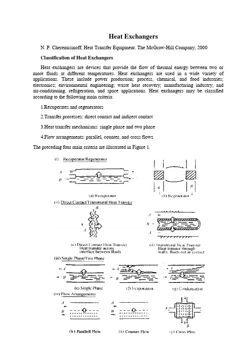
Heat ExchangersN. P. Cheremisinoff, Heat Transfer Equipment. The McGraw-Hill Company, 2000Classification of Heat ExchangersHeat exchangers are devices that provide the flow of thermal energy between two or more fluids at different temperatures. Heat exchangers are used in a wide variety of applications. These include power production; process, chemical, and food industries; electronics; environmental engineering; waste heat recovery; manufacturing industry; and air-conditioning, refrigeration, and space applications. Heat exchangers may be classified according to the following main criteria:1.Recuperates and regenerators2.Transfer processes: direct contact and indirect contact3.Heat transfer mechanisms: single phase and two phase4.Flow arrangements: parallel, counter, and cross flowsThe preceding four main criteria are illustrated in Figure 1.Recuperation and RegenerationThe conventional heat exchangers shown diagrammatically in Figure la with heat transfer between two fluids is called a recuperate, because the hot stream A recovers (recuperates) some of the heat from stream B. The heat transfer is through a separating wall or through the interface between the streams as in the case of direct contact type of heat exchangers (Figure lc).In regenerators or in storage-type heat exchangers, the same flow passage (matrix) is alternately occupied by one of the two fluids. The hot fluid stores the thermal energy in the matrix; during the cold-fluid flow through the same passage later, energy stored will be extracted from the matrix. Therefore, thermal energy is not transferred through the wall as in a direct transfer type of heat exchanger. This cyclic principle is illustrated in Figure lb. While the solid is in the cold stream A it loses heat; while it is in the hot stream B it gains heat (i. e., it is regenerated). Some examples of storage-type heat exchangers are rotary regenerator for preheating the air in a large coal-fired steam power plant, gas turbine rotary regenerator, and fixed-matrix air presenters for blast furnace stoves, steel furnaces, open-hearth steel melting furnaces, and glass furnaces.Criteria used in the classification of heat exchangers, Regenerators can be classified as follows:1.Rotary regenerator2.Fixed-matrix regeneratorRotary regenerators can be further subclassified as:1.Disk type2.Drum typeIn a disk-type regenerator, the heat transfer surface is in a disk form and fluids flow axially. In a drum type, the matrix is in a hollow drum form and fluids flow radially.These regenerators are periodic flow heat exchangers. In rotary regenerators, the operation is continuous. To have this, the matrix moves periodically in and out of the fixed stream of gases. A rotary regenerator can be used for air heating. There are two kinds of regenerative air presenters used in convectional power plants: the rotating-plate type and the stationary-plate type. The rotor of the rotating-plate air heater is mounted within box housing and is installed with the heating surface in the form of plates. As the rotor rotates slowly, the heating surface is exposed alternately to flue gases and to the entering air. When the heating surface is placed in the flue gas stream, the heating surface is heated; and then when it is rotated by mechanical devices into the air stream, the stored heat is released to the air flow. Thus, the air stream is heated. In the stationary-plate air heater, the heating plates are stationary, while cold-air hoods-both top and bottom-are rotated across the heating plates; the heat transfer principles are the same as those of the rotating-plate regenerative air heater. In a fixed-matrix regenerator, the gas flows must be diverted to and from the fixed matrices. Regenerators are compact heat exchangers and they are designed for surface area density of up to approximately 6 600 m2 /m3.Transfer ProcessesAccording to transfer processes, heat exchangers are classified as direct contact type and indirect contact type.In direct contact type heat exchangers, heat is transferred between the cold and hot fluids through a direct contact between these fluids. There is no wall between hot and cold streams, and the heat transfer occurs through the interface between two streams as illustrated in Figure lc. In direct contact-type heat exchangers the streams are two immiscible liquids, a gas-liquid pair, or a solid particle-fluid combination. Spray and tray condensers and cooling towers are good examples of such heat exchangers.In an indirect contact type heat exchanger, the heat energy is exchanged between hot and cold fluids through a heat transfer surface (i.e. a wall separating the fluids). The cold and hot fluids flow simultaneously while heat energy is transferred through a separating wall as illustrated in Figure 16. Id. The fluids are not mixed.Indirect contact- and direct transfer-type heat exchangers are also called recuperates cooling towers; and tray condensers are examples of recuperates.Heat Transfer MechanismsHeat exchanger equipment can also be classified according to the heat transfer mechanisms as:1.Single-phase convection on both sides2.Single-phase convection on one side, rwo-phase convection on other side3.Two-phase convection on both sidesIn heat exchangers like economizers and air heaters in boilers, compressor intercoolers, automotive radiators, regenerators, oil coolers, space heaters, etc., single-phase convection occurs on both sides.Condensers, boilers and steam generators used in pressurized water reactors, power plants, evaporators, and radiators used in air-conditioning and space heating include the mechanisms of condensation, boiling, and radiation on one of the surfaces of the heat exchanger. Two-phase heat transfer could also occur on each side of the heat exchanger such as condensing on one side and boiling on the other side of the heat transfer surface. However, without phase change, we may also have a two-phase flow heat transfer mode as in the case of fluidized beds where a mixture of gas and solid particles transports heat to or from a heat transfer surface.Flow ArrangementsHeat exchangers may be classified according to the fluid-flow path through the heat exchanger. The three basic configurations are1.Parallel flow2.Counter flow3.Cross flowIn parallel flow (concurrent) heat exchangers, the two fluid streams enter together at one end, flow through in the same direction, and leave together at the other end. In counterflow (countercurrent) heat exchangers, two fluid streams flow in opposite directions. In single-crossflow heat exchangers, one fluid flows through the heat transfer surface at right angles to the flow path of the other fluid. Multipass crossflow configurations can also be arranged by having the basic arrangements in series. For example, in a U-baffled tube single-pass shell-and-tube heat exchanger, one fluid flows through the U-tube while the otherfluid flows first downward and then upward, crossing the flow path of the other fluid stream, which is also referred to as crosscounter, cross-parallel flow arrangements.The multipass flow arrangements are frequently used in heat exchanger designs, especially in shell-and-tube heat exchangers with baffles. The main difference between the flow arrangements lies in the temperature distribution along the length of the heat exchanger, and the relative amounts of heat transfer under given temperature specifications for specified heat exchanger surfaces (i.e., for given flow and specified temperatures, a counterflow heat exchanger requires a minimum area, a parallel flow heat exchanger requires a maximum area, while a crossflow heat exchanger requires an area in between).In the crossflow arrangement, the flow may be called mixed or unmixed, depending on the design. If both hot and cold fluids flow through individual flow channels with no fluid mixing between adjacent flow channels, each fluid stream is said to be unmixed. If one fluid flows inside the tubes, thus is not free to move in the transverse direction, and therefore is considered unmixed; on the other hand if another fluid is free to move in the transverse direction and mix itself, and therefore is called unmixed-mixed crossflow heat exchanger.General Design TerminoJogyThe rate of heat transfer from one fluid to another through a metal wall is proportional to the overall heat transfer coefficient, to the area of the metal wall, and to the temperature difference between the hot and cold fluid:Q = U o A MTD eWhen specifying a heat exchanger, the designer nearly always knows or can readily calculate the Q and MTDe terms for the process conditions. It is necessary only to evaluate the coefficient Uo in order to arrive at a proper value of the necessary heat transfer area. Unfortunately, Uo is a function of the actual exchanger design as well as of the fluid properties and fouling rates. For this reason, the design of a heat exchanger requires a trial-and-error calculation.The general procedure used in heat-exchanger design is as follows:1.Establish Q from process considerations.2.Establish MTD e from process considerations. Exchanger type and tube arrange ment will have some effect on MTD? as explained subsequently.3.Assume Uo is the overall duty coefficient.4.Calculate an assumed A from the assumed Uo.5.D etermine the physical dimensions of the applicable type heat exchanger from the calculated A.6.Calculate the fluid pressure drops through the exchanger and modify internals if required to obtain a reasonable balance between pressure drop and exchanger size.7.Calculate Uo from physical properties of the fluids, fouling factors, and theexchanger layout.8.Calculate A based on Q and the calculated valued of U o and MTD e.pare A calculated with A assumed and repeat the calculations until they are equal. (For almost any value of U0there is an exchanger design that satisfies the criterion that Acalculated equals A assumed. However, only a few of these designs are reasonable. ) When heat flows from a fluid on one side of a tube to a fluid on the other side of a tube, it must overcome the following resistances:1.R i0 is the resistance of the fluid laminar "film" on the inside of the tube,2.r io, is the resistance (fouling factor) of foreign material deposited on the inside of the tube,3.r m is the resistance of the metal wall,4.r o is the resistance (fouling factor) of foreign material deposited on the outside of the tube,5.R o is the resistance of the fluid laminar film on the outside of the tube.The sum of these five resistances is R,, the total resistance; andU o=l/R t,The fouling factors r io and r o are estimated based on experience or taken from typical values listed in steam tables. The term r w is calculated from the thickness and thermal conductivity of the metal wall. Rio and R o are functions of mass velocity and physical properties of the fluid and are evaluated from the applicable correlations in temrs of h io and h where 1 /R o = h o, and 1 /R io = h o. The h terms are known as the film coefficients.The resistance terms contain an area dimension, m2, which usually refers to the square meters of surface area at which the resistance occurs. Since the resistance terms must be added to obtain the overall resistance, the area dimensions of each term must refer to the same surface area rather than to its own area. This rationalizes the terms and makes them additive. Standard practice is to use the outside tube area as the basis for calculation and specification of exchangers. As shown earlier, the usual nomenclature indicates this by the subscript io. For example, h io is the inside coefficient based on the outside tube area. For a tube or pipe, h io = h i ( d i/ d o), where hi is the inside coefficient based on the inside tube area. This factor is already included in the correlations presented.The commercially clean coefficient is the overall coefficient which can be expected when a new exchanger is first placed into service and before process fouling of the tubes occurs. It is calculated according to the following:l/U c = Rc = R io + R o + r w+0. 00025The 0.00025 term is an estimated resistance to heat transfer to allow for fouling in a new exchanger due to tube roller lubricants, mild corrosion from hydrostatic testing water, and so on. It is assumed that this allowance is split evenly between the shell-side and the tube-side surfaces.The operating temperatures of the exchanger are usually set by process conditions. However, in certain cases, the exchanger designer will establish the operating temperatures.Temperature of Streams to StorageThe maximum temperature of a stream going to atmospheric storage generally is set by safety, economics, or special process considerations.A stream going to an atmospheric tank at sea level should not exceed that temperature at which its true vapor pressure is 89.6 kPa abs. This value is reduced 11.3 kPa for each 1, 000 m elevation. For heavy streams whose true vapor pressure is difficult to determine, the maximum temperature to tankage should be the lower value of either 28t below the ASTM initial boiling point or 8t below the minimum flash point.Streams should not be sent to tankage at temperatures above 90 to 120℃. Operation in or above this temperature range could cause the tank water heel to flash to steam, resulting in a boll over.The selection of the optimum temperature of a stream going to cone-roof tankage is generally based on an economic balance between the cost of incremental cooler surface and cooling water and the savings due to reduced vapor losses.Opportunity for optimizing the temperature of a stream going to storage is greatest for intermediate products. However, special considerations are required for the following cases;1.Streams that are stored prior to a process requiring refrigeration of the feed.2.Steams whose properties are permanently degraded by high storage temperature.3.Streams those are stored prior to blending. The storage temperatures for such streams should be chosen after considering the properties and temperature of the blend, assuming no heat loss in intermediate tankage.The maximum allowable cooling-water outlet temperatures, set by fouling considerations, for coolers other than box coolers are:•Salt water, 48℃•Brackish water, 51℃•F resh water, 54℃The maximum temperature used for a project should be checked with the affiliate, since this has an important bearing on the economics of surface selection.An equally, if not more, important criteria is the maximum allowable cooling-water temperature. This is the average film temperature at the water outlet. These limits are: • Salt water, 60℃• Fresh water, 65℃For box coolers, the maximum cooling-water outlet temperature is 65℃for both salt and fresh water. If water film temperatures are allowed to exceed the preceding values, catastrophic fouling could result.In those cases where the hot stream outlet temperature is equal to or lower than the maximum allowable cooling-water outlet temperature, a brief economic study may be required to set the optimum cooling-water outlet temperature. The cooling-water outlet temperature is normally determined by designing the exchanger so that the log mean temperature difference correction factor ( Fn) is equal to the minimum allowable value (0. 8). Keep in mind the possibility of using a two-shell pass unit or two shells in series in this situation.At times, a condenser or cooler might be designed using a large amount of cooling water with a relatively low outlet temperature. Consideration should be given to reuse of this water in other coolers where the water outlet temperature may be the maximum permissible. Box coolers invariably operate with reused water.The selection of the optimum arrangement of a series of exchangers (exchanger train) requires a more complex economic study because of the greater number of variables. In many cases, not only must the total heat requirement be distributed between exchangers and a furnace (or steam}, but also several streams at different heat levels may be available to supply the heat. Investment costs must be considered for the exchangers, for the related coolers, and for the furnace (or steam heater). Operating costs for the preceding units must also be included.It is possible to transfer too much heat at the cold end of an exchanger train and thus “pinch out” or require excessive surface at a point farther along when the stream being heated has increased in temperature. Also, in an effort to squeeze out as much heat as possible from a source, the approach temperature (temperature difference between the stream outlet temperatures) used may be too close to be economical. Obviously, for cases where the cost of fuel is high there is more incentive to take a critical look at the economics.The driving force of the heat transfer mechanism is the effective temperature difference, MTD e, between hot and cold fluids. This temperature difference is calculated from the counter-current log mean temperature difference with correction factors applied to account for the actual flow arrangement.In the case of condensation or vaporization, the relationship between Q and the temperature of the fluid usually deviates appreciably from a straight line. In this case, it is necessary to divide the exchanger into zones so that Q is approximately linear with the temperatures for each zone. Based on the logarithmic mean temperature differences and heat duties for the individual zones, a weighted MTD e is obtained for the entire exchanger.Applications of Heat ExchangersMost common heat exchangers are two-fluid heat exchangers. Three-fluid heat I exchangers are widely used in cryogenics. They are also used in various heat exchangers that are used in chemical and process industries, such as air separation systems, purification and liquefaction of hydrogen, and ammonia gas synthesis. Three and multicomponent heat exchangers are very complex to design. They may also include multicomponent two-phase convection as in condensation of mixed vapors in the distillation of hydrocarbons.Heat exchangers are used in a wide variety of applications as in the process, power, air-conditioning, refrigeration, cryogenics, heat recovery, and manufacturing industries. In the power industry, various kinds of fossil boilers, nuclear steam generators, steam condensers, regenerators, and cooling towers are used. In the process industry, two-phase flow heat exchangers are used for vaporizing, condensing, and freezing in crystallization, and for fluidized beds with catalytic reaction. The air-conditioning and refrigeration industries need condensers and evaporators.Energy can be saved by direct contact condensation. By direct contact condensation of a vapor in liquid of the same substance under high pressure, thermal energy can be stored in a storage tank. When the energy is needed again, the liquid is depressurized and flashing occurs that results in producing vapor. The vapor can then be used for heating or as a working fluid for an engine.There have been abrupt developments in heat exchanger applications. One of the mainsteps for the early development of boilers was the introduction of the water-tube boilers. The demand for more powerful engines created a need for boilers that operated at higher pressures, and as a result, individual boilers were built larger and larger. The boiler units used in modern power plants for steam pressures above 1200 lb /in. (80 bar) consist of furnace water-wall tubes, superheaters, and such heat recovery accessories as economizers and air heaters. The development of modem boilers and of more efficient condensers for the power industry has represented a major milestone in engineering. In the pressurized water reactors (PWR), large-sized, inverted U-tube types of steam generators, each providing steam 300 to 400 MW of electrical power, are constructed. In the process industry, engineers are concerned with designing equipment to vaporize a liquid. In the chemical industry, the function of an evaporator is to vaporize a liquid (vaporizer) or to concentrate a solution by vaporizing part of the solvent. Evaporizers may also be used in the crystallization process. Often, the solvent is water, but in many cases the solvent is valuable and recovered for reuse. The vaporizers used in the process chemical industry cover a wide range of sizes and applications.换热器换热器的类型换热器是在两种或多种温度不同的流体间传递热量的一种设备;它有着广泛的应用范围,如动力生产,加工、化学工业及食品行业,电子工业,环境工程,废热回收,制造业,空调、制冷以及空间应用。
换热器Heat-exchanger

Mech/IITD
Shell-and-Tube Shell and Tube Heat Exch Exch.
Shell-and-tube heat exchangers contain a large number of tubes (sometimes several hundred) packed in a shell with their axes parallel to that of the shell.
Mech/IITD
Condenser/Boiler
Q = m h fg g
.
.
The heat capacity rate of a fluid during a phase-change process must approach infinity since the temperature change is practically zero. That is, C = m.Cp → ∞ when ∆T → 0, so that the heat transfer rate is a finite quantity quantity. Therefore Therefore, in heat exchanger analysis analysis, a condensing or boiling fluid is conveniently modeled as a fluid whose heat capacity rate is infinity. Mech/IITD
换热器专业术语-中英对照

换热器专业术语- 中英对照换热器heat exchan ger热交换器heat exchan ger紧凑式换热器compact heat exchan ger管式换热器 t ubula r heat exchan ger套管式换热器double-pipe heat exchan ger 间壁式换热器surface type heat exchan ger 表面式换热器surface type heat exchan ger 板管式换热器tube-on-sheet heat exchan ger 板翅式换热器plate-fin heat exchan ger板式换热器 pl ateheat exchan ger螺旋板式换热器spiral plateheat exchan ger 平板式换热器flat plateheat exchan ger顺流式换热器parall el flow heat exchan ger 逆流式换热器counte r flow heat exchan ger 流式换热器 cross-flow heat echanger折流式换热器turn back flow heat exchan ger 直接接触式换热器direct heat exchan ger旋转式换热器rotary heat exchan ger刮削式换热器scrape d heat exchan ger热管式换热器heat pipe exchan ger蓄热器recupe rator壳管式换热器shell and tube heat exchan ger 管板tube plate可拆端盖remova ble head管束bundle of tube管束尺寸size of tube bundle顺排管束in-line hank of tubes错排管束stagge red hank of tubes盘管coil蛇形管serpen tine coilU形管U-tube光管bare tube肋片管finned tube翅片管finned tube肋管finned tube肋管束finned tube bundle肋片fin套片platefin螺旋肋spiral fin整体肋integral fin纵向肋longit udinal fin钢丝肋wire fin内肋innerfi n肋片管尺寸 size of fin tube肋片厚度fin thickn ess肋距spacin g of fin肋片数pitchof fin肋片长度finned length肋片高度finned height肋效率fin effici ency换热面积heat exchan ge surface传热面积heat exchan ge surface冷却面积coolin g surface加热表面heat exchan ge surface基表面primary surface扩展表面extended surface肋化表面finned surface迎风表面face area流通表面flow area净截面积net area;effect i ve sectio nal area迎风面流速 face veloci ty净截面流速 ai r veloci ty at net area迎风面质量流速face veloci ty of mass净截面质量流速mass veloci ty at net area冷(热)媒有效流通面积effecti ve area for coolin g or heatin g medium 冷(热)媒流速veloci ty of coolin g or heatin g medium干工况dry conditi on;sensib l e coolin g conditi on湿工况wet conditi on;dehumi di fyi ng conditi on接触系数contact factor旁通系数bypass factor换热效率系数coeffi c ient of heat transm i ssio n effecti vene ss盘管风阻力 ai r pressu re drop of coil;air resist anceo f coil盘管水阻力 p ressu re drop of coolin g or heatin g medium表面冷却surface coolin g蒸发冷却evaporating coolin g冷却元件coolin g elemen t传热板plateheat exchan ger夹套型传热板clamp on heat exchan ger。
Heat Exchangers(换热器)

plate-fin heat exchanger
lamella heat exchanger
In the late 30s
shell and tube heat exchanger
• Since the 60s
heat pipe exchanger
• In the middle of the 70's
Cleaning steps:
• • • • Descaling cleaning Clearing-water cleaning Stripping antiseptic cleaning Passivation coating processing
Cleaning equipment:
• preliminary --- self-cleaning water filter
1.Direct contact heat exchanger
• Principle:Hot and cold fluid direct mixed with each other to transfer heat. • It is suitable for occasions where hot and cold fluids can be mixed, such as cold water tower, gas washing tower, spray type heat exchanger and so on.
In industry
• Heat exchangers are widely used in industry both for cooling and heating large scale industrial processes. The type and size of heat exchanger used can be tailored to suit a process depending on the type of fluid, its phase, temperature, density, viscosity, pressures, chemical composition and various other thermodynamic properties. • In many industrial processes there is waste of energy or a heat stream that is being exhausted, heat exchangers can be used to recover this heat and put it to use by heating a different stream in the process. This practice saves a lot of money in industry, as the heat supplied to other streams from the heat exchangers would otherwise come from an external source that is more expensive and more harmful to the environment.
换热器(双语)

赛科 PROPRIETARY INFORMATIONTO BE MAINTAINED IN CONFIDENCELEARNING & DEVELOPMENT SERVICES培训和开发服务PRESENTS课程介绍MODULE: Exchangers-1模块:热交换器-1DESIGNED FORENHANCING OPERATIONS KNOWLEDGE & SKILLS适用于提高操作知识和技能STUDENT PACKAGE学生部分SECCO赛科LEARNING AND DEVELOPMENT SERVICES培训和开发服务MODULE: Exchangers-1模块:热交换器1HEAT TRANSFER and SHELL & TUBE HEAT EXCHANGERS热传递和管壳式热交换器赛科培训和开发服务能量守恒–热交换器赛科培训和开发服务能量守恒–热交换器赛科培训和开发服务能量守恒–热交换器TABLE OF CONTENTS目录If viewing this TOC on a computer, you can move directly to a subject area by pointing with your cursor and single clicking.如果你在计算机上查看本目录,你可以通过移动光标到想要主题的标题上,单击之后直接进入到想要的主题区域INTRODUCTION (9)LEARNING ACTIVITIES (10)DEFINITION (11)G ENERAL C ATEGORIES OF H EAT E XCHANGER E QUIPMENT (12)HOW HEAT EXCHANGERS WORK (13)H EAT T RANSFER (13)M ETHODS OF H EAT T RANSFER (13)Convection (13)Conduction (17)Radiation (19)FACTORS THAT AFFECT HEAT TRANSFER (23)T YPE AND A MOUNT OF F LUIDS (25)T EMPERATURE D IFFERENCE (25)M ATERIALS U SED (25)C ONTAMINATION污染 (26)HEAT EXCHANGERS (27)赛科培训和开发服务能量守恒–热交换器O VERVIEW (27)T YPES OF H EAT E XCHANGERS (27)BASIC DESIGN OF HEAT EXCHANGERS (30)S HELL AND T UBE E XCHANGERS (30)C OMPONENTS OF S HELL AND T UBE E XCHANGERS (33)Shell Side Components (33)Tube Side Components (35)U-T UBE AND F IXED T UBE E XCHANGERS (37)U-Tube (37)Fixed Tube Sheets (39)DETERMINING THE FLOW OF PRODUCT STREAMS (41)T UBE S IDE P RODUCT S TREAMS (41)S HELL S IDE P RODUCT S TREAMS (43)CONDENSERS (45)H OT V APORS I N热蒸汽进口 (45)L IQUID O UT液体出口 (45)W ARM W ATER热水 (45)W ATER C OOLED C ONDENSERS (45)HEAT EXCHANGER OPERATING PARAMETERS AND PROBLEMS (47)O PERATING P ARAMETERS (47)O PERATING P ROBLEMS (49)外部泄漏:热交换器外部法兰、阀或垫圈的故障导致产品流向外界泄漏。
毕业论文《换热器》基础资料

换热器换热器(英语翻译:heat exchanger),是将热流体的部分热量传递给冷流体的设备,又称热交换器。
换热器主要应用于航空科技;航空安全、生命保障系统与航空医学。
换热器是化工、石油、动力、食品及其它许多工业部门的通用设备,在生产中占有重要地位。
在化工生产中换热器可作为加热器、冷却器、冷凝器、蒸发器和再沸器等,应用更加广泛。
换热器种类很多,但根据冷、热流体热量交换的原理和方式基本上可分三大类即:间壁式、混合式和蓄热式。
在三类换热器中,间壁式换热器应用最多。
金属换热器的分类间壁式换热器的类型夹套式换热器这种换热器是在容器外壁安装夹套制成,结构简单;但其加热面受容器壁面限制,传热系数也不高.为提高传热系数且使釜内液体受热均匀,可在釜内安装搅拌器.当夹套中通入冷却水或无相变的加热剂时,亦可在夹套中设置螺旋隔板或其它增加湍动的措施,以提高夹套一侧的给热系数.为补充传热面的不足,也可在釜内部安装蛇管. 夹套式换热器广泛用于反应过程的加热和冷却。
沉浸式蛇管换热器这种换热器是将金属管弯绕成各种与容器相适应的形状,并沉浸在容器内的液体中.蛇管换热器的优点是结构简单,能承受高压,可用耐腐蚀材料制造;其缺点是容器内液体湍动程度低,管外给热系数小.为提高传热系数,容器内可安装搅拌器。
喷淋式换热器这种换热器是将换热管成排地固定在钢架上,热流体在管内流动,冷却水从上方喷淋装置均匀淋下,故也称喷淋式冷却器.喷淋式换热器的管外是一层湍动程度较高的液膜,管外给热系数较沉浸式增大很多.另外,这种换热器大多放置在空气流通之处,冷却水的蒸发亦带走一部分热量,可起到降低冷却水温度,增大传热推动力的作用.因此,和沉浸式相比,喷淋式换热器的传热效果大有改善。
套管式换热器套管式换热器是由直径不同的直管制成的同心套管,并由U形弯头连接而成.在这种换热器中,一种流体走管内,另一种流体走环隙,两者皆可得到较高的流速,故传热系数较大.另外,在套管换热器中,两种流体可为纯逆流,对数平均推动力较大。
外文及翻译---换热器的优化选型
毕业设计(论文)外文翻译外文题目New plate heat exchanger optimization Sel ection译文题目新型板式换热器的优化选型系部机械工程系换热器的优化选型W. Lub 和 S.A. Tassoub英国米德尔塞克斯,布鲁内尔大学机械设计工程部【摘要】板式换热器的优化选型是根据换热器的用途和工艺过程中的参数和NTU=KA/MC=△t/△tm,即传热单元数NTU和温差比(对数平均温差—换热的动力)选择板片形状、板式换热器的类型和结构。
【关键词】平均温差 NTU 板式蒸发器冷凝器1 平均温差△tm从公式Q=K△tmA,△tm=1/A ∫A(t1-t2)dA中可知,平均温差△tm是传热的驱动力,对于各种流动形式,如能求出平均温差,即板面两侧流体间温差对面积的平均值,就能出换热器的传热量。
平均温差是一个较为直观的概念,也是评价板式换热器性能的一项重要指标。
1.1 对数平均温差的计算当换热器传热量为dQ,温度上升为dt时,则C=dQ/dt,将C定义为热容量,它表示单位时间通过单位面积交换的热量,即dQ=K(th -tc)dA=K△tdA,两种流体产生的温度变化分别为dth =-dQ/Ch,dtc=-dQ/Cc,d△t=d(th-tc)=dQ(1/Cc -1/Ch),则dA=[1/k(1/Cc-1/Ch)]·(d△t/△t),当从A=0积分至A=A0时,A=[1/k(1/Cc-1/Ch)]·㏑[(tho-tci)/(thi-tco)],由于两种流体间交换的热量相等,即Q=Ch (thi-tho)=Cc(tco-tci),经简化后可知,Q=KA0{[(tho-tci)-(thi-tco)]/㏑[(tho-tci)/(thi-tco)]},若△t1=t hi -tco,△t2=tho-tci,则Q=KA[(△t1-△t2)/㏑(△t1/△t2)]=KA△tm,式中的△tm=(△t1-△t2)/㏑(△t1/△t2)。
换热器外文翻译 (2)

Heat ExchangersKey Terms Baffles—evenly spaced partitions in a shell and tube heat exchanger that support the tubes, prevent vibration, control fluid velocity and direction, increase turbulent flow, and reduce hot spots. Channel head—a device mounted on the inlet side of a shell-and-tube heat exchanger that is used to channel tube-side flow in a multipass heat exchanger.Condenser—a shell-and-tube heat exchanger used to cool and condense hot vapors.Conduction—the means of heat transfer through a solid, nonporous material resulting from molecular vibration. Conduction can also occur between closely packed molecules.Convection—the means of heat transfer in fluids resulting from currents. Counterflow—refers to the movement of two flow streams in opposite directions; also called countercurrent flow.Crossflow—refers to the movement of two flow streams perpendicular to each other.Differential pressure—the difference between inlet and outlet pressures; represented as ΔP, or delta p.Differential temperature—the difference between inlet and outlet temperature; represented as ΔT, or delta t.Fixed head—a term applied to a shell-and-tube heat exchanger that has the tube sheet firmly attached to the shell.Floating head—a term applied to a tube sheet on a heat exchanger that is not firmly attached to the shell on the return head and is designed to expand (float) inside the shell as temperature rises. Fouling—buildup on the internal surfaces of devices such as cooling towers and heat exchangers, resulting in reduced heat transfer and plugging.Kettle reboiler—a shell-and-tube heat exchanger with a vapor disengaging cavity, used to supply heat for separation of lighter and heavier components in a distillation system and to maintain heat balance. Laminar flow—streamline flow that is more or less unbroken; layers of liquid flowing in a parallel path.Multipass heat exchanger—a type of shell-and-tube heat exchanger that channels the tubeside flow across the tube bundle (heating source) more than once.Parallel flow—refers to the movement of two flow streams in the same direction; for example, tube-side flow and shell-side flow in a heat exchanger; also called concurrent.Radiant heat transfer—conveyance of heat by electromagnetic waves from a source to receivers.Reboiler—a heat exchanger used to add heat to a liquid that was onceboiling until the liquid boils again.Sensible heat—heat that can be measured or sensed by a change in temperature.Shell-and-tube heat exchanger—a heat exchanger that has a cylindrical shell surrounding a tube bundle.Shell side—refers to flow around the outside of the tubes of ashell-and-tube heat exchanger. See also Tube side.Thermosyphon reboiler—a type of heat exchanger that generates natural circulation as a static liquid is heated to its boiling point.Tube sheet—a flat plate to which the ends of the tubes in a heat exchanger are fixed by rolling, welding, or both.Tube side—refers to flow through the tubes of a shell-and-tube heat exchanger; see Shell side.Turbulent flow—random movement or mixing in swirls and eddies of a fluid. Types of Heat Exchangers换热器的类型Heat transfer is an important function of many industrial processes. Heat exchangers are widely used to transfer heat from one process to another.A heat exchanger allows a hot fluid to transfer heat energy to a cooler fluid through conduction and convection. A heat exchanger provides heating or cooling to a process. A wide array of heat exchangers has been designed and manufactured for use in the chemical processing industry. In pipe coil exchangers, pipe coils are submerged in water or sprayed with water to transfer heat. This type of operation has a low heat transfer coefficient and requires a lot of space. It is best suited for condensing vapors with low heat loads.The double-pipe heat exchanger incorporates a tube-within-a-tube design. It can be found with plain or externally finned tubes. Double-pipe heat exchangers are typically used in series-flow operations in high-pressure applications up to 500 psig shell side and 5,000 psig tube side.A shell-and-tube heat exchanger has a cylindrical shell that surrounds a tube bundle. Fluid flow through the exchanger is referred to as tubeside flow or shell-side flow. A series of baffles support the tubes, direct fluid flow, increase velocity, decrease tube vibration, protect tubing, and create pressure drops.Shell-and-tube heat exchangers can be classified as fixed head, single pass; fixed head, multipass; floating head, multipass; or U-tube.On a fixed head heat exchanger (Figure 7.1), tube sheets are attached to the shell. Fixed head heat exchangers are designed to handle temperature differentials up to 200°F (93.33°C). Thermal expansion prevents a fixed head heat exchanger from exceeding this differential temperature. It is best suited for condenser or heater operations.Floating head heat exchangers are designed for high temperature differentia is above 200°F (93.33°C).During operation, one tube sheet is fixed and the other “floats” inside the shell.The floatingend is not attached to the shell and is free toexpand.Figure 7.1 Fixed Head Heat ExchangerReboilers are heat exchangers that are used to add heat to a liquid that was once boiling until the liquid boils again. Types commonly used in industry are kettle reboilers and thermosyphon reboilers.Plate-and-frame heat exchangers are composed of thin, alternating metal plates that are designed for hot and cold service. Each plate has an outer gasket that seals each compartment. Plate-and-frame heat exchangers have a cold and hot fluid inlet and outlet. Cold and hot fluid headers are formed inside the plate pack, allowing access from every other plate on the hot and cold sides. This device is best suited for viscous or corrosive fluid slurries. It provides excellent high heat transfer. Plate-and-frame heat exchangers are compact and easy to clean. Operating limits of 350 to 500°F (176.66°C to 260°C) are designed to protect the internal gasket. Because of the design specification, plate-and-frame heat exchangers are not suited for boiling and condensing. Most industrial processes use this design in liquid-liquid service.Air-cooled heat exchangers do not require the use of a shell in operation. Process tubes are connected to an inlet and a return header box. The tubes can be finned or plain. A fan is used to push or pull outside air over the exposed tubes. Air-cooled heat exchangers are primarily used in condensing operations where a high level of heat transfer is required.Spiral heat exchangers are characterized by a compact concentric design that generates high fluid turbulence in the process medium. As do otherexchangers, the spiral heat exchanger has cold-medium inlet and outlet and a hot-medium inlet and outlet. Internal surface area provides the conductive transfer element. Spiral heat exchangers have two internal chambers.The Tubular Exchanger Manufacturers Association (TEMA) classifies heat exchangers by a variety of design specifications including American Society of Mechanical Engineers (ASME) construction code, tolerances, and mechanical design:●Class B, Designed for general-purpose operation (economy and compactdesign)●Class C. Designed for moderate service and general-purpose operation(economy and compact design)●Class R. Designed for severe conditions (safety and durability) Heat Transfer and Fluid FlowThe methods of heat transfer are conduction, convection, and radiant heat transfer (Figure 7.2). In the petrochemical, refinery, and laboratory environments, these methods need to be understood well. A combination of conduction and convection heat transfer processes can be found in all heat exchangers. The best conditions for heat transfer are large temperature differences between the products being heated and cooled (the higher the temperature difference, the greater the heat transfer), high heating or coolant flow rates, and a large cross-sectional area of the exchanger.ConductionHeat energy is transferred through solid objects such as tubes, heads,baffles, plates, fins, and shell, by conduction. This process occurs when the molecules that make up the solid matrix begin to absorb heat energy from a hotter source. Since the molecules are in a fixed matrix and cannot move, they begin to vibrate and, in so doing, transfer the energy from the hot side to the cooler side.ConvectionConvection occurs in fluids when warmer molecules move toward cooler molecules. The movement of the molecules sets up currents in the fluid that redistribute heat energy. This process will continue until the energy is distributed equally. In a heat exchanger, this process occurs in the moving fluid media as they pass by each other in the exchanger. Baffle arrangements and flow direction will determine how this convective process will occur in the various sections of the exchanger.Radiant Heat TransferThe best example of radiant heat is the sun’s warming of the earth. The sun’s heat is conveyed by electromagnetic waves. Radiant heat transfer is a line-of-sight process, so the position of the source and that of the receiver are important. Radiant heat transfer is not used in a heat exchanger.Laminar and Turbulent FlowTwo major classifications of fluid flow are laminar and turbulent (Figure 7.3). Laminar—or streamline—flow moves through a system in thin cylindrical layers of liquid flowing in parallel fashion. This type of flow will have little if any turbulence (swirling or eddying) in it. Laminar flow usually exists atlow flow rates. As flow rates increase, the laminar flow pattern changes into a turbulent flow pattern. Turbulent flow is the random movement or mixing of fluids. Once the turbulent flow is initiated, molecular activity speeds up until the fluid is uniformly turbulent.Turbulent flow allows molecules of fluid to mix and absorb heat more readily than does laminar flow. Laminar flow promotes the development of static film, which acts as an insulator. Turbulent flow decreases the thickness of static film, increasing the rate of heat transfer. Parallel and Series FlowHeat exchangers can be connected in a variety of ways. The two most common are series and parallel (Figure 7.4). In series flow (Figure 7.5), the tube-side flow in a multipass heat exchanger is discharged into the tubeside flow of the second exchanger. This discharge route could be switched to shell side or tube side depending on how the exchanger is in service. The guiding principle is that the flow passes through one exchanger before it goes to another. In parallel flow, the process flow goes through multiple exchangers at the same time.Figure 7.5 Series Flow Heat ExchangersHeat Exchanger EffectivenessThe design of an exchanger usually dictates how effectively it can transfer heat energy. Fouling is one problem that stops an exchanger’s ability to transfer heat. During continual service, heat exchangers do not remain clean. Dirt, scale, and process deposits combine with heat to form restrictions inside an exchanger. These deposits on the walls of the exchanger resist the flow that tends to remove heat and stop heat conduction by i nsulating the inner walls. An exchanger’s fouling resistance depends on the type of fluid being handled, the amount and type of suspended solids in the system, the exchanger’s susceptibility to thermal decomposition, and the velocity and temperature of the fluid stream. Fouling can be reduced by increasing fluid velocity and lowering the temperature. Fouling is often tracked and identified usingcheck-lists that collect tube inlet and outlet pressures, and shell inlet and outlet pressures. This data can be used to calculate the pressure differential or Δp. Differential pressure is the difference between inlet and outlet pressures; represented as ΔP, or delta p. Corrosion and erosion are other problems found in exchangers. Chemical products, heat, fluid flow, and time tend to wear down the inner components of an exchanger. Chemical inhibitors are added to avoid corrosion and fouling. These inhibitors are designed to minimize corrosion, algae growth, and mineral deposits.Double-Pipe Heat ExchangerA simple design for heat transfer is found in a double-pipe heat exchanger.A double-pipe exchanger has a pipe inside a pipe (Figure 7.6). The outside pipe provides the shell, and the inner pipe provides the tube. The warm and cool fluids can run in the same direction (parallel flow) or in opposite directions (counterflow or countercurrent).Flow direction is usually countercurrent because it is more efficient. This efficiency comes from the turbulent, against-the-grain, stripping effect of the opposing currents. Even though the two liquid streams never come into physical contact with each other, the two heat energy streams (cold and hot) do encounter each other. Energy-laced, convective currents mix within each pipe, distributing the heat.In a parallel flow exchanger, the exit temperature of one fluid can only approach the exit temperature of the other fluid. In a countercurrent flowexchanger, the exit temperature of one fluid can approach the inlet temperature of the other fluid. Less heat will be transferred in a parallel flow exchanger because of this reduction in temperature difference. Static films produced against the piping limit heat transfer by acting like insulating barriers.The liquid close to the pipe is hot, and the liquid farthest away from the pipe is cooler. Any type of turbulent effect would tend to break up the static film and transfer heat energy by swirling it around the chamber. Parallel flow is not conducive to the creation of turbulent eddies. One of the system limitations of double-pipe heat exchangers is the flow rate they can handle. Typically, flow rates are very low in a double-pipe heat exchanger, and low flow rates are conducive to laminar flow. Hairpin Heat ExchangersThe chemical processing industry commonly uses hairpin heat exchangers (Figure 7.7). Hairpin exchangers use two basic modes: double-pipe and multipipe design. Hairpins are typically rated at 500 psig shell side and 5,000 psig tube side. The exchanger takes its name from its unusual hairpin shape. The double-pipe design consists of a pipe within a pipe. Fins can be added to the internal tube’s external wall to increase heat transfer. The multipipe hairpin resembles a typical shell-and-tube heat exchanger, stretched and bent into a hairpin.The hairpin design has several advantages and disadvantages. Among its advantages are its excellent capacity for thermal expansion because of its U-tube type shape; its finned design, which works well with fluids that have a low heat transfer coefficient; and its high pressure on the tube side. In addition, it is easy to install and clean; its modular design makes it easy to add new sections; and replacement parts are inexpensive and always in supply. Among its disadvantages are the facts that it is not as cost effective as most shell-and-tube exchangers and it requires special gaskets.Shell-and-Tube Heat ExchangersThe shell-and-tube heat exchanger is the most common style found inindustry. Shell-and-tube heat exchangers are designed to handle high flow rates in continuous operations. Tube arrangement can vary, depending on the process and the amount of heat transfer required. As the tube-side flow enters the exchanger—or “head”—flow is directed into tubes that run parallel to each other. These tubes run through a shell that has a fluid passing through it. Heat energy is transferred through the tube wall into the cooler fluid. Heat transfer occurs primarily through conduction (first) and convection (second). Figure 7.8 shows a fixed head,single-pass heat exchanger.Fluid flow into and out of the heat exchanger is designed for specific liquid–vapor services. Liquids move from the bottom of the device to the top to remove or reduce trapped vapor in the system. Gases move from top to bottom to remove trapped or accumulated liquids. This standard applies to both tube-side and shell-side flow.Plate-and-Frame Heat ExchangersPlate-and-frame heat exchangers are high heat transfer and high pressure drop devices. They consist of a series of gasketed plates, sandwiched together by two end plates and compression bolts (Figures 7.20 and 7.21). The channels between the plates are designed to create pressure drop and turbulent flow so high heat transfer coefficients can be achieved.The openings on the plate exchanger are located typically on one of the fixed-end covers.As hot fluid enters the hot inlet port on the fixed-end cover, it is directed into alternating plate sections by a common discharge header. The header runs the entire length of the upper plates. As cold fluid enters the countercurrent cold inlet port on the fixed-end cover, it is directed into alternating plate sections. Cold fluid moves up the plates while hot fluid drops down across the plates. The thin plates separate the hot and cold liquids, preventing leakage. Fluid flow passes across the plates one time before entering the collection header. The plates are designed with an alternating series of chambers. Heat energy is transferred through the walls of the plates by conduction and into the liquid by convection. The hot and cold inlet lines run the entire length of the plate heater and function like a distribution header. The hot and cold collection headers run parallel and on the opposite side of the plates from each other. The hot fluid header that passes through the gasketed plate heat exchanger is located in the top. This arrangement accounts for the pressure drop and turbulent flow as fluid drops over the plates and into the collection header. Cold fluid enters the bottom of the gasketed plate heat exchanger and travels countercurrent to the hot fluid. The cold fluid collection header is located in the upper section of the exchanger.Plate-and-frame heat exchangers have several advantages and disadvantages. They are easy to disassemble and clean and distribute heat evenly so there are no hot spots. Plates can easily be added or removed. Other advantages of plate-and-frame heat exchangers are their low fluid resistance time, low fouling, and high heat transfer coefficient. In addition, if gaskets leak, they leak to the outside, and gaskets are easy to replace.The plates prevent cross-contamination of products. Plate-and-frame heat exchangers provide high turbulence and a large pressure drop and are small compared with shell-and-tube heat exchangers.Disadvantages of plate-and-frame heat exchangers are that they have high-pressure and high-temperature limitations. Gaskets are easily damaged and may not be compatible with process fluids.Spiral Heat ExchangersSpiral heat exchangers are characterized by a compact concentric design that generates high fluid turbulence in the process medium (Figure 7.22). This type of heat exchanger comes in two basic types: (1) spiral flow on both sides and (2) spiral flow–crossflow. Type 1 spiral exchangers are used in liquid-liquid, condenser, and gas cooler service. Fluid flow into the exchanger is designed for full counterflow operation. The horizontal axial installation provides excellent self-cleaning of suspended solids.Type 2 spiral heat exchangers are designed for use as condensers, gas coolers, heaters, and reboilers. The vertical installation makes it an excellent choice for combining high liquid velocity and low pressure drop on the vapor-mixture side. Type 2 spirals can be used in liquid-liquid systems where high flow rates on one side are offset by low flow rates on the other.Air-Cooled Heat ExchangersA different approach to heat transfer occurs in the fin fan or air-cooled heat exchanger. Air-cooled heat exchangers provide a structured matrix of plain or finned tubes connected to an inlet and return header (Figure 7.23). Air is used as the outside medium to transfer heat away from the tubes. Fans are used in a variety of arrangements to apply forced convection for heattransfer coefficients. Fans can be mounted above or below the tubes in forced-draft or induced-draft arrangements. Tubes can be installed vertically or horizontally.The headers on an air-cooled heat exchanger can be classified as cast box, welded box, cover plate, or manifold. Cast box and welded box types have plugs on the end plate for each tube. This design provides access for cleaning individual tubes, plugging them if a leak is found, and rerolling to tighten tube joints. Cover plate designs provide easy access to all of the tubes. A gasket is used between the cover plate and head. The manifold type is designed for high-pressure applications.Mechanical fans use a variety of drivers. Common drivers found in service with air-cooled heat exchangers include electric motor and reduction gears, steam turbine or gas engine, belt drives, and hydraulic motors. The fan blades are composed of aluminum or plastic. Aluminum blades are d esigned to operate in temperatures up to 300°F (148.88°C), whereas plastic blades are limited to air temperatures between 160°F and 180°F(71.11°C, 82.22°C).Air-cooled heat exchangers can be found in service on air compressors, in recirculation systems, and in condensing operations. This type of heat transfer device provides a 40°F (4.44°C) temperature differential between the ambient air and the exiting process fluid.Air-cooled heat exchangers have none of the problems associated with water such as fouling or corrosion. They are simple to construct and cheaper to maintain than water-cooled exchangers. They have low operating costs and superior high temperature removal (above 200°F or 93.33°C). Their disadvantages are that they are limited to liquid or condensing service and have a high outlet fluid temperature and high initial cost of equipment. In addition, they are susceptible to fire or explosion in cases of loss of containment.。
化工传热英文讲义-换热器(heatexchangers)
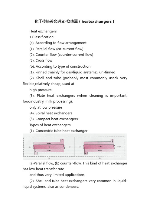
化工传热英文讲义-换热器(heatexchangers)Heat exchangers1.Classification:(a). According to flow arrangement(1). Parallel flow (co-current flow)(2). Counter flow (counter-current flow)(3). Cross flow(b). According to type of construction(1). Finned (mainly for gas/liquid systems), un-finned(2). Shell and tube (probably most commonly used), very flexible,relatively cheap, used athigh pressure(3). Plate heat exchangers (when cleaning is important, foodindustry, milk processing),only at low pressure(4). Spiral heat exchangers(5). Compact heat exchangersTypes of heat exchangers(1). Concentric tube heat exchanger(a)Parallel flow, (b) counter-flow. This kind of heat exchanger has low heat transfer rateand thus very limited applications.(2). Shell and tube heat exchangers-very common in liquid-liquid systems, also as condensers.One shell pass and one tube pass (cross-counterflow)One shell pass and two tube passesTwo shell passes and four tube passesCross flow heat exchangers:(a) (b)(a)Finned with both fluids unmixed, (b) un-finned with one fluid mixed and the other unmixed Compact heat exchanger(a) Fin-tube (flat tubes, continuous plate fins), (b) Fin-tube (circulartubes, continuous plate fins), (c) Fin-tube (circular tubes, circular fins),(d) plate-fin (single pass), (e) plate-fin (single pas).Large specific surface area > 700 m2 /m3 but laminar flow because ofsmall size of channels (low heat transfer coefficients).Overall heat transfer coefficient:Where:R f′′-fouling factor (additional thermal resistance)R w-thermal resistance in the wall separating hot and cold fluid (corresponding to conduction) depends on material and geometryηo-overall surface efficiency de fined q=ηo?A(T b?T∞)Typical values of fouling factor:Typical values of overall heat transfer coefficientsEnergy balance (for all types of heat exchangers)Heat load –net change of internal energy in hot and cold fluid:Subscript h – hot fluid, subscript c – cold fluidIf no phase change and specific heat is constant:Energy transfer from hot to cold fluid:In general T h and T c vary along heat transfer surface.In engineering applications the driving force for the heat transfer is expressed in terms of inlet and outlet temperatures and:F- correction factor for non-parallel flowsEnergy balance:This form of energy balance is always used in engineering calculations and designing of heat exchagersCalculations based on log mean temperature differenceParallel flowCounter flowSpecial operating conditionsTemperature distribution depends on thermal capacity of hot C?=m??c p,? and cold C?=m??c p,c fluid.During boiling/ condensation of a single component fluid/ vapour the temperature is constant assuming.For equal thermal capacities of both fluid local temperature difference is constant.Multi-pass and cross flow heat exchangersThe flow conditions can be more complex but the equations developedfor parallel flow heat exchangers can still be used but log meantemperature difference has to be modified:Calculate the driving force for counter current flow and multiply bycorrection factor F (depends on inlet and outlet temperatures and flowpattern) taken from the literature/graphs.Correction factor for two shells and four passes heat exchanger.Correction factor for cross flow heat exchanger with both fluids unmixed.Calculations based on effectiveness –NTU (number of transfer units) methodIf all inlet and outlet temperatures are given the Log MeanTemperature Difference method is recommended, but if only inlettemperatures are given (typical design problem) use of LMTD requiresiterative procedure.In such cases effectiveness-NTU method is better.Effectiveness of heat exchanger is defined as the ratio of actual heattransfer rate to the maximum possible heat transfer rate:Heat transfer rate can be easily calculated if ε, T h,i and T c,i are known as the actual heat transfer rate can be calculated from:Specific relations between NTU and ε depend on the type of heatexchanger and are given in the literature:For concentric tube, counterflow heat exchanger:For other types of heat exchangers algebraic relation are more complex and graphs are commonly used.Effectiveness of single pass, cross-flow heat exchanger with both fluidsun-mixed.SummaryA. The nature of the whole process for which heat exchanger is designedfrequently determines its type:a) hygiene/cleanliness is important (food industry) –plate heat exchanger,b) When process is carried out at high pressure – shell and tube,c) When space is limited – compact heat exchanger,d) Cost is also a major factor, shell and tube exchangers are cheap, plateor compact exchangers are expensive.B. If the inlet and outlet temperatures and mass flow rate of fluid (A) andthe inlet temperature of fluid (B) are known LMTD is recommended.1. Calculate heat load from energy balance for fluid (A)2. Assume flow rate and inlet temperature of fluid (B) and calculateoutlet temperature of fluid (B), or assume outlet temperature of fluid (B)(often temperature constrains) and calculate flow rate from energybalance for fluids (A) and (B).3. Draw the temperature distributions and calculate driving force4. Calculate heat transfer coefficients5. Calculate overall heat transfer coefficient (see methodology above)6. Calculate the heat transfer areaC. Alternatively (if not all temperatures are given) effectiveness-NTUmethod can be used.。
换热器英汉互译

换热器英汉互译
换热器是一种用于传递热量的设备,一般由管道、容器和换热管束等部分组成。
它的作用是在两种介质之间传递热量,使温度差异减小,达到调节温度的目的。
换热器广泛应用于各种工业领域,如化工、石油、制药、食品、造纸等行业。
在换热器的英汉互译中,常用的英文术语包括heat exchanger、heat transfer equipment、heat exchanger tube、shell and tube heat exchanger、plate heat exchanger等。
其中,heat exchanger 是最常见的术语,是指能够将热量从一个介质传递到另一个介质的设备。
换热器的分类也有很多种,根据不同的工况和工艺要求,可以选择不同类型的换热器来满足。
例如,管壳式换热器适用于高粘度、高含固体、易结垢的介质,而板式换热器则适用于对传热效率和压降有较高要求的介质。
总之,换热器是工业生产过程中必不可少的设备,对于提高生产效率、降低能耗、改善产品质量等方面都有着重要作用。
因此,对于换热器的英汉互译及其相关知识的掌握,是各行各业从事相关工作人员必须具备的基本能力。
- 1 -。
常见换热器形式 英文缩写
常见换热器形式英文缩写English: Common forms of heat exchangers include shell and tube (STHE), plate heat exchanger (PHE), finned tube heat exchanger (FTHE), double pipe heat exchanger (DPHE), and air-cooled heat exchanger (ACHE). Shell and tube heat exchangers consist of a shell with a bundle of tubes inside, allowing for efficient heat transfer between two fluids. Plate heat exchangers utilize a series of plates to facilitate heat exchange, offering high efficiency and compactness. Finned tube heat exchangers enhance heat transfer by adding fins to the exterior of tubes, increasing surface area. Double pipe heat exchangers feature two concentric pipes for fluid flow, suitable for low to moderate pressure applications. Air-cooled heat exchangers employ ambient air to remove heat from a process fluid, making them suitable for remote or outdoor locations where water is scarce or costly.中文翻译: 常见的换热器形式包括壳管式换热器(STHE)、板式换热器(PHE)、翅片管式换热器(FTHE)、双管式换热器(DPHE)和风冷式换热器(ACHE)。
换热器科技名词概念
换热器科技名词概念中文名称:换热器英文名称:heat exchanger其他名称:热互换器概念:将热量从一种载热介质传递给另一种载热介质的装置。
应用学科:航空科技(一级学科);航空平安、生命保障系统与航空医学(二级学科)以上内容由全国科学技术名词审定委员会审定发布百科名片换热器换热器(英语翻译:heat exchanger),是将热流体的部份热量传递给冷流体的设备,又称热互换器。
换热器是化工、石油、动力、食物及其它许多工业部门的通用设备,在生产中占有重腹地位。
在化工生产中换热器可作为加热器、冷却器、冷凝器、蒸发器和再沸器等,应用加倍普遍。
换热器种类很多,但依照冷、热流体热量互换的原理和方式大体上可分三大类即:间壁式、混合式和蓄热式。
在三类换热器中,间壁式换热器应用最多。
目录进展介绍大体概念分类注意事项行业状况概述管壳式市场前景金属换热间壁式混合式蓄热式陶瓷浮头式设计要求优缺点涡流热膜换热器概述性能特点相关内容质检内容质检方式安装方式进展历史机组构造常见问题新型气动喷涂螺旋折流麻花管螺旋管式螺旋板式变声速压侵蚀防护侵蚀防护清洗注意事项系统查验防除垢管网清洁展开进展介绍大体概念分类注意事项行业状况概述管壳式市场前景金属换热间壁式混合式蓄热式陶瓷浮头式设计要求优缺点涡流热膜换热器概述性能特点相关内容质检内容质检方式安装方式进展历史机组构造常见问题新型气动喷涂螺旋折流麻花管螺旋管式螺旋板式变声速压侵蚀防护侵蚀防护清洗注意事项系统查验防除垢管网清洁展开编辑本段进展换热器是一种在不同温度的两种或两种以上流体间实现物料之间热量传递的节能设备,是使热量由较高的流体传递给温度较低的流体,使流体温度达到流程规定的指标,以知足进程工艺条件的需要,同时也提高能源利用率的要紧设备之一。
换热器行业涉及暖通、压力容器、中水处置设备等近30多种产业,彼此形成产业链条。
据《2021-2017年中国换热器行业进展前景预测与转型升级分析报告》[1]数据显示2020年中国换热器产业市场规模在500亿元左右,要紧集中于石油、化工、冶金、电力、船舶、集中供暖、制冷空调、机械、食物、制药等领域。
暖通设备名称中英文对照

暖通设备名称中英文对照第一篇:暖通设备名称中英文对照印尼暖通专业设备中英文对照编号中文名称英文名称屋顶风机Power Roof Ventilator风冷分体空调机Air-cooled Air Conditioner风冷柜式空调机Air-cooled Packaged Air Conditioner风冷壁挂式空调机Air-cooled Wall Mounted Air Conditioner天花板嵌入式(四向气流)空调机(室内机)Ceiling Mounted Cassette Type(Four Flow)Air Conditioner(Indoor Unit)空调室外机Air Conditioner(Outdoor Unit)风机盘管机组Fan Coil Unit轴流风机Axial Fan水冷冷水机组Water-cooled Chiller冷却塔Cooling tower冷却水泵Cooling Water Pump冷水泵Chilled Water Pump膨胀定压装置Pressurization Device空气处理机Air Handling送风机Force draft fan回风机Air Return Fan排风机组Exhaust Air Unit空气处理机组(新风降温型)Air Handling Unit(Fresh Air Cooling Type)新风机组(降温型)Fresh Air Unit(Cooling Type)集中空调控制系统Control System for Central Air Conditioning System防爆轴流风机Explosion-proof Axial Fan第二篇:暖通词汇-中英文对照0703制冷专业英语基本术语制冷 refrigeration 蒸发制冷 evaporative refrigeration 沙漠袋 desert bag 制冷机 refrigerating machine 制冷机械 refrigerating machinery 制冷工程 refrigeration engineering 制冷工程承包商refrigeration contractor 制冷工作者refrigerationist 制冷工程师refrigeration engineer 制冷技术员refrigeration technician 制冷技师 refrigeration technician 制冷技工 refrigeration mechanic 冷藏工人 icer 制冷安装技工 refrigeration installation mechanic 制冷维修技工 refrigeration serviceman 冷藏链 cold chain 制冷与空调维修店 refrigeration and air conditioning repair shop 冷藏 refrigerated prvservation管道与附件配管 tubing 空调制冷配管 ACR tubing 管道 piping,tubing 制冷管路 refrigeration pipe line 系统酸状况 acid condition system 退火 annealing 加压元件 pressure imposing element 检修门access door 气封vapor lock 主管main 歧管mainfold 集管header 盐水管 brine line 盐水集管 brine header 旁通管 by-pass 套管 tube-within-a-tube 伸缩弯 expansion loop 存油弯 oil loop 液环liquid loop 配管tubing 空调制冷配管ACR tubing 管道piping,tubing制冷管路refrigeration pipe line 系统酸状况acid condition system 退火 annealing加压元件 pressure imposing element 检修门 access door 气封vapor lock 主管 main 歧管 mainfold 集管 header 盐水管 brine line 盐水集管 brine header 旁通管 by-pass 套管 tube-within-a-tube 伸缩弯 expansion loop 存油弯 oil loop 液环 liquid loop吸入管 suction line,return line 消声器 muffer分液贮存器 accumulator排出管 discharge line,hot gas line 液体管 liquid line 冷凝液管 condensate line 管道附件 fittings 软接头 connecting hose 加液接头 charging connection快装接头quick-release coupling,quick-coupler 法兰flange 接管 coupling收缩管 constricted tube 异径内承插管 reducing coupling 异径外承插管 double male reduction 异径套管 reducing bushing 螺纹接管 nipple 阀 valve截止阀 stop valve 止回阀 check valve 角阀 angle valve球阀 ball type valve,ball valve 闸阀 gate valve 操作阀 service valve 防通阀 bypass valve 二通阀 two-way valve 三通阀 three-way valve 塞子 plug 端盖 cap 垫 gasket 垫料 gasket 填料 packing 喇叭口接头 flared joint 扩口工具 flaring tool 胀口工具 swaging tool 弯曲弹簧 bending spring 弹簧弯管器 bending spring 扭矩扳手 torquewrench 压力容器 pressure vessel 贮液筒/器 surge drum 高压贮液筒 high pressure receiver 低压贮液筒 low pressure receiver 低压平衡筒accumulator,surge drum 均压管/平衡管equalizer 均压罐equalizer tank平衡罐 balance tank 液体分离器 suction trap 气液分离器flash chamber 经济器economizer 喷射器ejector 搅拌器agitator 抽气回收装置 purge recovery unit 排空 pump-down 循环泵circulation pump 液位指示器liquid level indicator 窥镜sight glass 液体流动指示器liquid flow indicator 吸入压力表suction gauge 排出压力表discharge gauge 净化系统purge recovery system 油分离器 oil separator 集液器 liquid trap 集油器 oil receiver,oil trap 不凝性气体分离器 non condensable gas purger 放空气器gas purger 干燥器dehydrator,drier 过滤器filter,screen,strainer 干燥过滤器 drier-filter 脱水 dehydration 干燥 drying 干燥剂 desiccant 硅胶 silica gel活性铝activated carbon 分子筛molecular sieve 润滑lubrication 滑油冷却器 oil cooler中间冷却器intercooler,interstage cooler 闪发式中间冷却器flash intercooler 膨胀容器expansion tank 冷凝器英语冷凝器condenser 冷凝液 condensate空冷式冷凝器air-cooled condenser 风冷式冷凝器air-cooled condenser自然对流空冷式冷凝器natural convecton air-cooled condenser强制通风式冷凝器forced draught condenser 冷凝风机condensate fan线绕式冷凝器wire and tube condenser 水冷式冷凝器water-cooled condenser 沉浸式盘管冷凝器 submerged coil condenser 套管式冷凝器double pipe condenser 壳管式冷凝器shell and tube condenser 组合式冷凝器 multishell condenser卧式壳管式冷凝器 closed shell and tube condenser卧式冷凝器 closed condenser立式壳管式冷凝器 open shell and tube condenser 立式冷凝器open condenser,vertical condenser 壳盘管式冷凝器shell and coil condenser 分隔式冷凝器split condenser 淋激式冷凝器atmospheric condenser 溢流式冷凝器 bleeder-type condenser 蒸发式冷凝器evaporative condenser 板式冷凝器plate-type condenser空冷板式冷凝器 air-cooled plate-type condenser 水冷板式冷凝器 water-cooled plate-type condenser焊接板式冷凝器 welded sheet condenser 螺旋板式冷凝器 spiral sheet condenser 冷凝-贮液器condenser-receiver 混合式冷凝器barometric condenser 液化器 liquefier冷凝水泵 condensate pump 冷凝器梳 condensate comb 预冷盘管 desuperheating coil 过冷器 subcooler 中间冷却器 intercooler 盐水冷却器brine cooler 气-液回热器liquid or suction heat exchanger 回热器 superheater 紊流器 turbulator 预冷器 precooler 级间冷却器 interstage cooler 饮水冷却器 drinking-water cooler 喷泉式饮水冷却器 bubbler-type drinking water cooler 冷藏间冷却器cold-storage cooler 盐水(水)冷却器 brine(water)cooler 空气冷却器air cooler,forced draught 干式空气冷却器dry-type air cooler 强制循环空气冷却器forced-circulation air cooler 自然对流空气冷却器 natural-convection air cooler 空气冷却机组 air-cooler unit 蒸发盘管干燥盘管 drier coil 冷却盘管 cooling coil 蒸发盘管 expansion coil 蓄冷盘管 hold-voer coil 直接蒸发盘管 direct expansion coil 制冷剂分配器refrigerant distributor 支承板tube support 蓄冷板hold-over plate 共晶混合物板 eutectic plate 折流板 baffle 滴水盘drip tray 冷藏库排管冷却排管cooling coil,cooling grid 冷却排管组cooling battery 顶排管 overhead coil 墙排管 wall coil,wall grid 蓄冷排管hold-over coil,hold-over grid 蓄冷板 hold-over plate 冷却塔自然通风式冷却塔atmpspheric cooling tower,natural draught cooling tower 机械通风式冷水塔mechanical draught cooling tower吸风式冷水塔induced draught cooling tower 送风式冷水塔forced draught cooling tower 水膜式冷水塔 film cooling tower 水滴式冷水塔 drop cooling tower 喷雾式冷水塔 spray cooling tower 拉西环 Rasching rings 温度接近值 approach 水垢 scale 水垢抑制剂scale inhibitor 藻类algae 防藻剂algaecide 淀渣slime升压阀 back-up valve冷水塔water cooling tower,cooling tower 凉水塔water cooling tower,cooling tower 冷却塔water cooling tower,cooling tower 喷水池 spray pond干式冷水塔 dry cooling tower 湿-干式冷水塔 wet-dry cooling tower冷水塔填料 packing of cooling tower,fill of cooling tower 膜式填料 film packing帘栅形填料grid packing,grid fill 片式填料plate packing,plate fill 松散填料 random packing,random fill 飞溅式填料 splash packing 蒸发器壳盘管式蒸发器 shell-and-coil evaporator 壳管式蒸发器 shell-and-tube evaporator 喷淋式蒸发器 spray-type evaporator 立管式蒸发器 vertical-type evaporator平行管蒸发器 receway coil 螺旋管式蒸发器spiral tube evaporator “V”型管蒸发器herringbone type evaporator 沉浸式盘管蒸发器submerged evaporator 板式蒸发器plate-type evaporator 螺旋板式蒸发器spiral sheet evaporator平板式蒸发器plate-type evaporator,tube-in-sheet evaporator管板式蒸发器tube-on-sheet evaporator 凹凸板式蒸发器embossed-plate evaporator 吹胀式蒸发器roll-bond evaporator 压焊板式蒸发器roll-bond evaporator 制冰块器的蒸发器ice cube maker evaporator 结冰式蒸发器 ice-bank evaporator 蓄冰式蒸发器ice-bank evaporator 结霜蒸发器frosting evaporator 除霜蒸发器defrosting evaporator 无霜蒸发器 nonfrosting evaporator 强制通风蒸发器forced circulation evaporator 冷液式蒸发器liquid cooling evaporator 封套式蒸发器 wrap-round evaporator 蒸发器evaporator 直接冷却式蒸发器direct evaporator 直接式蒸发器direct evaporator 间接冷却式蒸发器 indirect cooled evaporator 间接式蒸发器indirect evaporator 干式蒸发器dry expansion evaporator 满液式蒸发器flooded evaporator 再循环式蒸发器recirculation-type evaporator 强制循环式蒸发器pump-feed evaporator 制冷剂制冷剂(制冷工质)refrigerant 高温制冷剂high temperature refrigerant 低压制冷剂low pressure refrigerant 中温制冷剂medium temperature refrigerant 中压制冷剂medium pressure refrigerant 低温制冷剂low temperature refrigerant 高压制冷剂high pressure refrigerant 氟利昂freon 卤化碳制冷剂halocarbo refrigerant 氟利昂11 freon 11 氟利昂12 freon 12 氟利昂13 freon 13 氟利昂14 freon 14 氟利昂22 freon 22 氟利昂113 freon 113 氟利昂125 freon 125 氟利昂134a freon 134a 氟利昂152a freon 152a 碳氢化合物制冷剂hydrocarbon refrigerant 甲烷methane 乙烷ethane 丙烷 propane 丁烷 butane 异丁烷 isobutane乙烯 ethylene无机化合物制冷剂 inorganic compund refrigerant 氨 ammonia 二氧化碳 carbon dioxide 二氧化硫 sulphur dioxide 干冰 dry ice 共沸制冷剂azeotropic mixture refrigerant 氟里昂500 freon 500 氟里昂501 freon 501 氟里昂502 freon 502 氟里昂503 freon 503 氟里昂504 freon 504近共沸溶液制冷剂 near azeotropic mixture refrigerant非共沸溶液制冷剂 nonazeotropic mixture refrigerant 润滑油润滑油lubricant oil 冷冻机油refrigeration oil 冷冻油refrigerant oil 凝点 condensation point 闪点 flash point 浊点 cloud point 絮凝点flock point 流动点pour point 起泡foaming 皂化saponify 油泥 sludge 结碳 carbonization制冷装置试验与操作试运转 commissioning 吹污 flush气密性试验gas-tight test,air-right test 密闭容器closed container 漏气 air infiltration 放气 air vent检漏 leak hunting,leak detection 检漏仪 leak detector 卤素灯 halide torch电子检漏仪 electronic leak detector 真空试验 vacuum test 试验压力test pressure 工作压力operating pressure,working pressure 最高工作压力highest operating pressure 气密试验压力gas-tight test pressure 设计压力 design pressure平衡压力 balance pressure 充气aerate,gas charging 制冷剂充注refrigerant charging 首次充注 initial charge 保护充注 holding charge,service charge 制冷剂不足lack of refrigerant,under-charge,gas shortage 缺液 starveling 充灌台 charging board 充灌量 charge 充注过多 overcharge 供液过多 overfeeding 制冷剂抽空 pump down of refrigerant 降温试验 pull down test 制冷[功能]试验 refrigeration test 卸载起动 no-load starting,unloaded start 卸载机构 unloader 闪发flash vaporization,instantaneous vaporization 闪发气体flash gas 不凝性气体 non condensable gas 气体排除 gas purging,degassing,gasoff 阀针跳动 hammering,needle hammer 阀振荡hunting of a valve 阀片跳动 valve flutter,valve bounce 短期循环short-cycling 异常温升 overheating 泄漏 leak 气蚀 cavitation 制冷剂瓶 refrigerant cylinder,gas bottle 检修用瓶 service cylinder,gas bottle 紧急泄放阀 emergency-relief valve 检修阀 service valve 安全阀pressure relief valve 抽空阀pump out valve 加油阀oil charge valve 放油阀oil drain valve 放空阀purge valve 充灌阀charging valve 喷液阀 liquid injection valve制冷装置制冷装置 refrigerating installation,refrigerating plant工业制冷装置industrial refrigerating plant 商业制冷装置commercial refrigerating plant 中心站房 central station 成套机组self-contained system 规范安装code installation 制冷回路refrigerating circuit 热平衡 heat balance 货物负荷 product load 操作负荷 service load 设计负荷 design load 负荷系数 load factor 制冷系统自动调节流量调节flow regulation 制冷剂控制器refrigerant control 膨胀阀 expansion valve 节流阀 throttle valve 热力膨胀阀 thermostatic expansion valve 热电膨胀阀 thermal electric expansion valve 内平衡热力膨胀阀internal equalizer thermostaice expansion valve外平衡热力膨胀阀 external equalizer thermostaice expansion valve 外平衡管 external equalizer pipe 内平衡管 internal equalizer pipe蒸发器阻力损失 pressure drop of evaporator 同工质充注 same material charge 交*充注 cross charge 吸附充注 absorptive charge 气体充注 gas charge膨胀阀过热度 superheat degree of expansion valve过热温度调节superheat temperature regulation 膨胀阀容量expansion valve capacity 手动膨胀阀 hand expansion valve 自动膨胀阀 automatic expansion valve 浮球调节阀 float regulation valve 浮球阀 float valve低压浮球阀 low pressure float valve 高压浮球阀 high pressure float valve 流量调节flow regualation 制冷剂控制器refrigerant control 膨胀阀expansion valve 节流阀throttle valve 热力膨胀阀thermostatic expansion valve 热电膨胀阀thermal electric expansion valve 内平衡热力膨胀阀 internal equalizer thermostaice expansion valve 外平衡热力膨胀阀external equalizerthermostaice expansion valve 外平衡管 external equalizer pipe 内平衡管internal equalizer pipe 蒸发器阻力损失pressure drop of evaporator 同工质充注 same material charge 交*充注 cross charge 吸附充注absorptive charge 气体充注gas charge 膨胀阀过热度superheat degree of expansion valve 过热温度调节superheat temperature regulation 膨胀阀容量 expansion valve capacity 手动膨胀阀hand expansion valve 自动膨胀阀automatic expansion valve 浮球调节阀 float regulation valve 浮球阀 float valve 低压浮球阀 low pressure float valve 高压浮球阀 high pressure float valve 恒压膨胀阀constant pressure expansion valve 能量调节capacity regulator 单机能量调节 capacity regulation of single unit 卸载能量调节 capacity regulation of load drainage 程序指令式能量调节系统capacity regulation system of program order 电磁阀solenoid valve 电磁滑阀magnetic slide valve 三通电磁阀three way magnetic valve制冷能力及计算术语英语运行工况 operating conditions 标准性能 standard rating 标准工况 standard condition 空调工况 air conditioning condition 内部条件 internal conditions 外部条件 external conditions 蓄热 accumulation of heat 蓄冷 accumulation of cold 制冰能力 ice-making capacity热泵用压缩机的供热系数 heat-pump compressor coefficient of performance 容积效率volumetric efficiency 容积输气量vulumetric displacement 实际输气量 actual displacement 理论输气量 theoretical displacement 冷凝热量 condenser heat 过冷热量heat of subcooling 过热热量 superheat运转工况下的制冷量 rating under working conditions标准制冷量 standard rating 名义工况 normal conditions 试验工况 test conditions 轴功率 brake power 效率 efficiency 指示效率 indicated efficiency 机械效率 mechanical efficiency总效率 overall efficiency制冷系数coefficient of performance(COP)制冷压缩机的制冷系数 refrigerating compressor coefficient of performance 热力完善度thermodynamical perfectness 能效比energy efficiency ratio(EER)热泵供热系数 heat-pump coefficient of performance空调有效显热制冷量useful sensible heat capacity of air conditioner空调有效潜热(减湿)制冷量useful latent heat(dehumidifyying)capacity of air conditioner 空调器有效总制冷量 useful total capacity of air conditioner制冷剂循环量circulating mass of refrigerant 制冷剂循环容积circulating volume of refrigerant 单位压缩功 compress work per mass 示功图indicator diagram 指示功indicated work 摩擦功frictional work 功率power 摩擦功率frictional power 指示功率indicated power 理论功率idea power 制冷量refrigerating capacity 总制冷量gross refrigerating capacity 净制冷量net refrigerating capacity 单位制冷量refrigerating capacity per weighing 单位容积制冷量 refrigerating capacity per unit of swept volume 制冷系统制冷量 system refrigerating capacity 单位轴功率制冷量refrigerating effect per shaft power 压缩冷凝机组制冷量compressor condensing unit refrigerating capacity 制冷压缩机制冷量refrigerant compressor capacity 蒸发器净制冷量net cooler refrigerating capacity制冷暖通行业品牌中英文对照AEROFLEX “亚罗弗”保温AL CO “艾科”自控Alerton 雅利顿Alfa laval阿法拉伐ARMSTRONG “阿姆斯壮”保温AUX 奥克斯BELIMO 瑞士“搏力谋”BERONOR西班牙“北诺尔”电加热器BILTUR 意大利“百得” BOSIC “柏诚”自控BROAD 远大Burnham美国“博恩汉”锅炉CALPEDA意大利“科沛达”水泵CARLY 法国“嘉利”制冷配件Carrier 开利Chigo 志高Cipriani 意大利斯普莱力CLIMAVENETA意大利“克莱门特” Copeland“谷轮”压缩机CYRUS意大利”赛诺思”自控DAIKIN 大金Danfoss丹佛斯Dorin “多菱”压缩机DUNHAM-BUSH 顿汉布什DuPont美国“杜邦”制冷剂Dwyer 美国德威尔EBM “依必安”风机ELIWELL意大利“伊力威”自控EVAPCO美国“益美高”冷却设备EVERY CONTROL意大利“美控” Erie 怡日FRASCOLD 意大利“富士豪”压缩机FRICO瑞典“弗瑞克”空气幕FUJI “富士”变频器FULTON 美国“富尔顿”锅炉GENUIN “正野”风机GREE 格力GREENCOOL格林柯尔GRUNDFOS “格兰富”水泵Haier 海尔Hisense 海信HITACHI 日立Honeywell 霍尼韦尔Johnson 江森Kelon 科龙KRUGER瑞士“科禄格”风机KU BA德国“库宝”冷风机Liang Chi 良机LIEBERT 力博特MARLEY “马利”冷却塔Maneurop法国“美优乐”压缩机McQuary 麦克维尔Midea 美的MITSUBISHI三菱Munters 瑞典“蒙特”除湿机Oventrop德国“欧文托普”阀门Panasonic 松下RANCO “宏高”自控REFCOMP意大利“莱富康”压缩机RIDGID 美国“里奇”工具RUUD美国“路德”空调RYODEN “菱电”冷却塔SanKen “三垦”变频器Samsung 三星SANYO 三洋SASWELL英国森威尔Schneider 施耐德SenseAir 瑞典“森尔”传感器SIEMENS 西门子SINKO “新晃“空调SINRO “新菱”冷却塔STAND “思探得”加湿器SWEP 舒瑞普TECKA “台佳”空调Tecumseh“泰康”压缩机TRANE 特灵TROX德国“妥思”VASALA芬兰“维萨拉”传感器WILO德国“威乐”水泵WITTLER 德国”威特”阀门YORK 约克ZENNER德国“真兰”计量蒸汽喷射式制冷系统英语蒸汽喷射制冷 steam jet refrigeration 蒸汽喷射制冷机 steam-jet refrigerating machine 蒸发式蒸汽喷射制冷机evaporation-type steam jet refrigeration machine 混合式蒸汽喷射制冷机contact-type steam jet refrigerating machine 蒸汽喷射制冷系统 steam jet refrigerating system 蒸汽喷射器steam ejector 主喷射器main ejector 辅助喷射器 auxiliary ejector 喷射系数 jet coefficient 主冷凝器main condenser 辅助冷凝器auxiliary condenser 多效蒸发multieffective evaporation 高位安装 high-level installation 低位安装 low-level installation 高低位安装 high-low-level installation 一般制冷换热器英语换热器heat exchanger 热交换器heat exchanger 紧凑式换热器compact heat exchanger 管式换热器tubular heat exchanger 套管式换热器double-pipe heat exchanger 间壁式换热器 surface type heat exchanger 表面式换热器 surface type heat exchanger 板管式换热器 tube-on-sheet heat exchanger 板翅式换热器 plate-fin heat exchanger 板式换热器 plate heat exchanger螺旋板式换热器 spiral plate heat exchanger平板式换热器 flat plate heat exchanger 顺流式换热器 parallel flow heat exchanger逆流式换热器 counter flow heat exchanger *流式换热器 cross-flow heat echanger 折流式换热器 turn back flow heat exchanger 直接接触式换热器direct heat exchanger 旋转式换热器rotary heat exchanger 刮削式换热器scraped heat exchanger 热管式换热器heat pipe exchanger 蓄热器 recuperator壳管式换热器 shell and tube heat exchanger 管板 tube plate 可拆端盖 removable head 管束 bundle of tube 管束尺寸 size of tube bundle 顺排管束 in-line hank of tubes 错排管束 staggered hank of tubes 盘管 coil蛇形管 serpentine coil U形管 U-tube 光管 bare tube 肋片管finned tube 翅片管 finned tube 肋管 finned tube肋管束 finned tube bundle 肋片 fin 套片 plate fin 螺旋肋 spiral fin 整体肋 integral fin 纵向肋 longitudinal fin 钢丝肋 wire fin 内肋inner fin肋片管尺寸 size of fin tube 肋片厚度 fin thickness 肋距 spacing of fin 肋片数 pitch of fin 肋片长度 finned length 肋片高度 finned height 肋效率 fin efficiency换热面积heat exchange surface 传热面积heat exchange surface 冷却面积 cooling surface 加热表面 heat exchange surface 基表面 primary surface 扩展表面 extended surface 肋化表面 finned surface 迎风表面face area 流通表面flow area 净截面积net area;effective sectional area 迎风面流速 face velocity 净截面流速air velocity at net area 迎风面质量流速 face velocity of mass 净截面质量流速mass velocity at net area 冷(热)媒有效流通面积effective area for cooling or heating medium 冷(热)媒流速velocity of cooling or heating medium 干工况dry condition;sensible cooling condition 湿工况 wet condition;dehumidifying condition 接触系数 contact factor 旁通系数 bypass factor 换热效率系数 coefficient of heat transmission effectiveness 盘管风阻力 air pressure drop of coil;air resistance of coil 盘管水阻力 pressuredrop of cooling or heating medium 表面冷却 surface cooling 蒸发冷却 evaporating cooling 冷却元件 cooling element 盐水冷却系统开式盐水冷却系统open brine system 闭式盐水系统closed brine system 盐水箱 brine bank 盐水混合箱 brine mixing tank 盐水溢流箱 brine return tank 盐水回流箱 brine return tank 盐水膨胀箱brine balance tank 盐水加热器brine heater 盐水冷却器brine cooler 盐水筒brine drum 盐水集管brine header 盐水泵brine pump 盐水喷雾 brine spray 盐水喷淋 brine sparge吸收式制冷机英语吸收式制冷机 absorption refrigerating machine 吸收式制冷系统absorption refrigerating system 间歇式吸收系统intermittent absoprtion system 连续循环吸收式系统continuous cycle absorption system固体吸收式制冷solid absorption refrigeration 氨-水吸收式制冷机 ammonia/water absorption refrigerating machine 单级氨-水吸收式制冷机single stage ammonia/water absorption refrigerating machine 多级氨-水吸收式制冷机multistage ammonia/water absorption refrigerating machine 双级氨-水吸收式制冷机ammonia/water absorption refrigerating machine with two stage absorption process双级发生和双级吸收式氨-水制冷机 ammonia/water absorption refrigerating machine with two stage generation and absoprtion process 分解 decomposition 水解 hydrolysis 扩散 diffusion 能量增强剂energy booster 缓蚀剂anticorrsive 发生不足incomplete boiling 吸收不足incomplete absorption 喷淋密度sprinkle density 溴化锂 lithium bromide溴化锂水溶液 aqueous solution of lithium bromide氨水溶液aqueous solution of ammonia 吸收剂absorbent,absorbing agent 吸附剂 adsorbent 溶液 solution 浓度concentration 溶解度 solubility 溶剂 solvent 溶质 solute 浓溶液rich solution,concentrated solution 稀溶液weak solution,diluted solution 溶液分压 partial pressure of liquor 吸收absorption 吸附 adsorption吸收式制冷absorption refrigeration 吸附式制冷adsorption refrigeration 工质对 working substance 热力系数 heat ratio 放气范围 deflation ratio 焓-浓度图 enthalpy concentration chart 溴化锂吸收式制冷机 lithiumbromide absorption refrigerating machine 单效型溴化锂吸收式制冷机 single-effect lithiumbromide absorption refrigerating machine 两效型溴化锂吸收式制冷机double-effect lithiumbromide absorption refrigerating machine 单筒型溴化锂吸收式制冷机one-shell lithiumbromide absorption refrigerating machine 双筒型溴化锂吸收式制冷机two-shell lithiumbromide absorption refrigerating machine 三筒型溴化锂吸收式制冷机three-shell lithiumbromide absorption refrigerating machine 两级溴化锂吸收式制冷机two-stage lithiumbromide absorption refrigerating machine 直燃式溴化锂吸收式制冷机direct-fired lithiumbormide absorption refrigerating machine 溴化锂吸收式冷温水机组 lithiumbromide absorption water heater chiller 无泵型溴化锂吸收式制冷机lithiumbromide absorption refrigerating machine with bubble pump 蒸汽型吸收式制冷机 steam operated absorption refrigerating machine 热水型吸收式制冷机hot water operated absorption refrigerating machine 发生器 generator 沉浸式发生器submerged generator 喷淋式发生器spray-type generator 立式降膜式发生器 vertical falling film generator 直燃式发生器 direct-fired generator 高压发生器 high pressure generator 低压发生器 low pressure generator 吸收器 absorber 喷淋式吸收器spray absorber 降膜式吸收器 falling film absorber 立式降膜式吸收器vertical falling film absorber 卧式降膜式吸收器horizontal falling film absorber 喷淋装置 spray system 溶液换热器 solutionheat exchanger溶晶管 anti-crystallinic pipe 抽气装置 purging system 精馏器rectifier 屏蔽泵shield pump 发生器泵 generator pump 吸收器泵absorber pump 蒸发器泵 evaporator pump 溶液泵 solution pump 氨水泵 aqua-ammonia pump 混合阀 mixing valve压缩机制冷系统及机组制冷系统refrigeration system 制冷机refrigerating machine机械压缩制冷系统mechanical compression refrigeration system蒸气压缩制冷系统 vapour compression refrigeration system 压缩式系统 compression system 压缩机 compressor制冷压缩机refrigerating compressor,refrigerant compressor 吸气端 suction end 排气端 discharge end 低压侧 low pressure side 高压侧 high pressure side 蒸发压力 evaporating pressure 吸气压力 suction pressure,back pressure 排气压力discharge pressure 蒸发温度 evaporating temperature 冷凝压力 condensing pressure 冷凝温度condensing temperature 吸气温度suction temperature 回气温度back temperature 排气温度discharge temperature 压缩比 compression ratio 双效压缩 dual compression 单级压缩single-stage compression 双级压缩compound compression 多级压缩multistage compression 压缩级compression stage 低压级low pressure stage 高压级high pressure stage 中间压力intermediate pressure 中间冷却intercooling 多级膨胀multistage expansion 湿压缩wet compression 干压缩dry compression 制冷系统refrigerating system 机械制冷系统 mechanical refrigerating system 氟利昂制冷系统 freon refrigerating system 氨制冷系统 ammonia refrigerating system 压缩式制冷系统 compression refrigerating system 单级压缩制冷系统 single-stage compression refrigeration system 双级压缩制冷系统 two-stage compression refrigeration system 多级制冷系统multistage refrigerating system 复叠式制冷系统cascade refrigerating system 混合制冷剂复叠系统mixed refrigerant cascade 集中制冷系统central refrigerating plant 直接制冷系统direct refrigeration system 直接膨胀供液制冷系统refrigeration system with supply liqiud direct expansion 重力供液制冷系统refrigeration system with supply liquid refrigerant for the evaporator by gravity 液泵供液制冷系统 refrigeration system with supply liquid refrigerant for evaporator by liquid pump 间接制冷系统 indirect refrigeration system 融霜系统 defrosting system 热气融霜系统 defrosting system by superheated vapour 电热融霜系统eletrothermal defrosting system 制冷系统故障breakdown of the refrigerating system 冰堵freeze-up 冰塞ice plug 脏堵filth blockage 油堵 greasy blockage 液击(冲缸、敲缸)slugging 湿行程 wet stroke 镀铜现象 appearance of copper-plating 烧毁 burn-out 倒霜 frost back 制冷机组 refrigerating unit压缩机组 compressor unit开启式压缩机组open type compresssor unit 开启式压缩机open type compressor半封闭式压缩机组semihermetic compressor unit 半封闭式压缩机semihermetic compressor 全封闭式压缩机组hermetically sealed compressor unit全封闭式压缩机 hermetically sealed compressor 压缩冷凝机组condensing unit全封闭式压缩冷凝机组 hermetically sealed condensing unit半封闭式压缩冷凝机组semihermetically sealed condensing unit开启式压缩冷凝机组 open type compressor condensing unit 工业用压缩冷凝机组industrial condensing unit 商业用压缩冷凝机组 commercial condensing unit 整马力压缩冷凝机组integral horsepower condensing unit分马力压缩冷凝机组 fractional horsepower condensing unit 跨式制冷机组 straddle refrigerating unit涡流管制冷英语涡流制冷效应vortex refrigerating effect 兰克-赫尔胥效应Ranque-Hilsch effect 涡流管制冷 vortex tube refrigeration 涡流管vortex tube 兰克管 Ranque tube 膨胀喷嘴 expansion injector 涡流室 vortex device 分离孔板 separation orifice 调节阀 control valve 膨胀压力比expansion pressure ratio 冷气流分量cold gas fraction 热气流分量 hot gas fraction 冷却效应 cooling effect 加热效应 heating effect冷却效率cooling efficiency磁制冷英语磁热效应magnetocaloric effect 磁制冷 magnetic refrigeration磁制冷机magnetic refrigerating machine 磁冰箱magnetic refrigerator 透平压缩机及零部件英语涡流swirl 叶片颤振blade flutter 叶片通过频率blade passing frequency 喘振surging 脱流stall 叶轮反应度(反作用度)impeller reaction 叶轮 impeller 半开式叶轮unshrouded impeller 闭式叶轮shrouded impeller 叶片blade,vane 导流叶片组件 pre-rotary vane assembly 扩压器 diffuser 蜗壳scroll 滑动slip 透平压缩机turbocompressor 离心式压缩机centrifugal compressor 轴流式压缩机 axial flow compressor 刚性轴离心式压缩机 stiff-shaft centrifugal compressor 挠性轴离心式压缩机 flexibleshaft centrifugal compressor 亚音速压缩机 subsonic compressor 超音速压缩机 supersonic compressor太阳能制冷与供热英语太阳能solar energy 太阳常数solar constant 太阳能系统solar energy system 被动式太阳能系统passive solar energy system 主动式太阳能系统 active solar energy system 混合式太阳能系统 hybrid solar energy system 太阳能制冷solar cooling 太阳能热机驱动制冷 solarpowered cooling 太阳能吸收式制冷机 solar absorption refrigerating machine 光-热转换制冷photothermal refrigeration 光-电转换制冷photoelectricalrefrigeration 太阳能蒸汽喷射制冷机solar steam jet refrigerating machine 连续式太阳能吸收式制冷机continual solar absorption refrigerating machine 间歇式太阳能吸收式制冷机intermittent solar absorption refrigerating machine敞开式太阳能吸收式制冷机open solar absorption refrigerating machine太阳能空调装置 solar air-conditioning system 太阳能制冷系统solar energy cooling system,solar cooling system 太阳能集热器solar collector选择式吸收表面selective absorber surface 电淀积electrodeposition平板型太阳能集热器 flat plate solar collector 真空管太阳能集热器 tubular solar collector,vacuum tube collector聚光型太阳能机热器focus solar collector 集热量heat-collecting capacity 集热温度 heat-collecting temperature 集热效率heat-collecting efficiency 蓄热介质 heat storge medium 岩石蓄热容器 rock storge container 辅助热源 supplementary heat source 太阳能贮存系统solar energy storge system 太阳能供热系统 solar heating system,solar space heating installation自然循环闭式供水系统 natural convection closed water system 强制循环闭式供水系统forced convection in a closed water system热风供热系统 warm air heating system家用太阳能热水系统 solar domestic water heating system容积式压缩机及零部件英语容积式压缩机 positive displacement compressor 往复式压缩机(活塞式压缩机)reciprocating compressor回转式压缩机rotary compressor 滑片式压缩机sliding vane compressor单滑片回转式压缩机 single vane rotary compressor滚动转子式压缩机rolling rotor compressor 三角转子式压缩机triangle rotor compressor 多滑片回转式压缩机 multi-vane rotary compressor 滑片 blade旋转活塞式压缩机rolling piston compressor 涡旋式压缩机scroll compressor 涡旋盘 scroll 固定涡旋盘 stationary scroll,fixed scroll 驱动涡旋盘 driven scroll,orbiting scroll 斜盘式压缩机(摇盘式压缩机)swash plate compressor 斜盘swash plate 摇盘wobble plate 螺杆式压缩机screw compressor 单螺杆压缩机single screw compressor 阴转子female rotor 阳转子male rotor 主转子main rotor 闸转子 gate rotor 无油压缩机 oil free compressor 膜式压缩机diaphragm compressor 活塞式压缩机reciprocating compressor 单作用压缩机single acting compressor 双作用压缩机double acting compressor 双效压缩机 dual effect compressor 双缸压缩机twin cylinder compressor 闭式曲轴箱压缩机closed crankcase compressor 开式曲轴箱压缩机 open crankcase compressor 顺流式压缩机 uniflow compressor 逆流式压缩机 return flow compressor 干活塞式压缩机dry piston compressor 双级压缩机compund compressor 多级压缩机 multistage compressor 差动活塞式压缩机stepped piston compound compressor,differential piston compressor 串轴式压缩机tandem compressor,dual compressor 截止阀 line valve,stop valve 排气截止阀 discharge line valve 吸气截止阀 suction line valve 部分负荷旁通口 partial duty port 能量调节器 energy regulator 容量控制滑阀 capacity control slide valve 容量控制器capacity control 消声器muffler 联轴节coupling 曲轴箱crankcase 曲轴箱加热器crankcase heater 轴封crankcase seal,shaft seal 填料盒 stuffing box轴封填料 shaft packing 机械密封 mechanical seal 波纹管密封bellows seal 转动密封rotary seal 迷宫密封labyrinth seal 轴承bearing滑动轴承 sleeve bearing 偏心环 eccentric strap 滚珠轴承 ballbearing 滚柱轴承 roller bearing 滚针轴承 needle bearing 止推轴承thrust bearing 外轴承 pedestal bearing 臼形轴承 footstep bearing 轴承箱 bearing housing 止推盘 thrust collar 偏心销 eccentric pin 曲轴平衡块crankshaft counterweight,crankshaft balance weight 曲柄轴 crankaxle偏心轴eccentric type crankshaft 曲拐轴crankthrow type crankshaft 连杆 connecting rod 连杆大头 crank pin end 连杆小头piston pin end 曲轴crankshaft 主轴颈main journal 曲柄crank arm,crank shaft 曲柄销 crank pin 曲拐 crank throw 曲拐机构 crank-toggle 阀盘 valve disc 阀杆 valve stem 阀座 valve seat 阀板 valve plate 阀盖 valve cage 阀罩 valve cover阀升程限制器 valve lift guard 阀升程 valve lift 阀孔 valve port 吸气口 suction inlet压缩机气阀compressor valve 吸气阀suction valve 排气阀delivery valve 圆盘阀 disc valve 环片阀 ring plate valve 簧片阀 reed valve 舌状阀cantilever valve 条状阀beam valve 提升阀poppet valve 菌状阀 mushroom valve 杯状阀 tulip valve 缸径 cylinder bore 余隙容积 clearance volume 附加余隙(补充余隙)clearance pocket 活塞排量 swept volume,piston displacement 理论排量 theoretical displacement 实际排量actual displacement 实际输气量actual displacement,actual output of gas 气缸工作容积 working volume of the cylinder 活塞行程容积 piston displacement 气缸 cylinder 气缸体 cylinder block 气缸壁 cylinder wall 水冷套 water cooled jacket 气缸盖(气缸头)cylinder head 安全盖(假盖)safety head 假盖false head 活塞环 piston ring 气环 sealing ring 刮油环 scraper ring 油环scrape ring 活塞销piston pin 活塞piston 活塞行程piston stroke 吸气行程 suction stroke 膨胀行程 expansion stroke 压缩行程compression stroke 排气行程discharge stroke 升压压缩机booster compressor 立式压缩机vertical compressor 卧式压缩机horizontal compressor 角度式压缩机 angular type compressor 对。
换热器外文翻译 (2)
Heat ExchangersKey Terms Baffles—evenly spaced partitions in a shell and tube heat exchanger that support the tubes, prevent vibration, control fluid velocity and direction, increase turbulent flow, and reduce hot spots. Channel head—a device mounted on the inlet side of a shell-and-tube heat exchanger that is used to channel tube-side flow in a multipass heat exchanger.Condenser—a shell-and-tube heat exchanger used to cool and condense hot vapors.Conduction—the means of heat transfer through a solid, nonporous material resulting from molecular vibration. Conduction can also occur between closely packed molecules.Convection—the means of heat transfer in fluids resulting from currents. Counterflow—refers to the movement of two flow streams in opposite directions; also called countercurrent flow.Crossflow—refers to the movement of two flow streams perpendicular to each other.Differential pressure—the difference between inlet and outlet pressures; represented as ΔP, or delta p.Differential temperature—the difference between inlet and outlet temperature; represented as ΔT, or delta t.Fixed head—a term applied to a shell-and-tube heat exchanger that has the tube sheet firmly attached to the shell.Floating head—a term applied to a tube sheet on a heat exchanger that is not firmly attached to the shell on the return head and is designed to expand (float) inside the shell as temperature rises. Fouling—buildup on the internal surfaces of devices such as cooling towers and heat exchangers, resulting in reduced heat transfer and plugging.Kettle reboiler—a shell-and-tube heat exchanger with a vapor disengaging cavity, used to supply heat for separation of lighter and heavier components in a distillation system and to maintain heat balance. Laminar flow—streamline flow that is more or less unbroken; layers of liquid flowing in a parallel path.Multipass heat exchanger—a type of shell-and-tube heat exchanger that channels the tubeside flow across the tube bundle (heating source) more than once.Parallel flow—refers to the movement of two flow streams in the same direction; for example, tube-side flow and shell-side flow in a heat exchanger; also called concurrent.Radiant heat transfer—conveyance of heat by electromagnetic waves from a source to receivers.Reboiler—a heat exchanger used to add heat to a liquid that was onceboiling until the liquid boils again.Sensible heat—heat that can be measured or sensed by a change in temperature.Shell-and-tube heat exchanger—a heat exchanger that has a cylindrical shell surrounding a tube bundle.Shell side—refers to flow around the outside of the tubes of ashell-and-tube heat exchanger. See also Tube side.Thermosyphon reboiler—a type of heat exchanger that generates natural circulation as a static liquid is heated to its boiling point.Tube sheet—a flat plate to which the ends of the tubes in a heat exchanger are fixed by rolling, welding, or both.Tube side—refers to flow through the tubes of a shell-and-tube heat exchanger; see Shell side.Turbulent flow—random movement or mixing in swirls and eddies of a fluid. Types of Heat Exchangers换热器的类型Heat transfer is an important function of many industrial processes. Heat exchangers are widely used to transfer heat from one process to another.A heat exchanger allows a hot fluid to transfer heat energy to a cooler fluid through conduction and convection. A heat exchanger provides heating or cooling to a process. A wide array of heat exchangers has been designed and manufactured for use in the chemical processing industry. In pipe coil exchangers, pipe coils are submerged in water or sprayed with water to transfer heat. This type of operation has a low heat transfer coefficient and requires a lot of space. It is best suited for condensing vapors with low heat loads.The double-pipe heat exchanger incorporates a tube-within-a-tube design. It can be found with plain or externally finned tubes. Double-pipe heat exchangers are typically used in series-flow operations in high-pressure applications up to 500 psig shell side and 5,000 psig tube side.A shell-and-tube heat exchanger has a cylindrical shell that surrounds a tube bundle. Fluid flow through the exchanger is referred to as tubeside flow or shell-side flow. A series of baffles support the tubes, direct fluid flow, increase velocity, decrease tube vibration, protect tubing, and create pressure drops.Shell-and-tube heat exchangers can be classified as fixed head, single pass; fixed head, multipass; floating head, multipass; or U-tube.On a fixed head heat exchanger (Figure 7.1), tube sheets are attached to the shell. Fixed head heat exchangers are designed to handle temperature differentials up to 200°F (93.33°C). Thermal expansion prevents a fixed head heat exchanger from exceeding this differential temperature. It is best suited for condenser or heater operations.Floating head heat exchangers are designed for high temperature differentia is above 200°F (93.33°C).During operation, one tube sheet is fixed and the other “floats” inside the shell.The floatingend is not attached to the shell and is free toexpand.Figure 7.1 Fixed Head Heat ExchangerReboilers are heat exchangers that are used to add heat to a liquid that was once boiling until the liquid boils again. Types commonly used in industry are kettle reboilers and thermosyphon reboilers.Plate-and-frame heat exchangers are composed of thin, alternating metal plates that are designed for hot and cold service. Each plate has an outer gasket that seals each compartment. Plate-and-frame heat exchangers have a cold and hot fluid inlet and outlet. Cold and hot fluid headers are formed inside the plate pack, allowing access from every other plate on the hot and cold sides. This device is best suited for viscous or corrosive fluid slurries. It provides excellent high heat transfer. Plate-and-frame heat exchangers are compact and easy to clean. Operating limits of 350 to 500°F (176.66°C to 260°C) are designed to protect the internal gasket. Because of the design specification, plate-and-frame heat exchangers are not suited for boiling and condensing. Most industrial processes use this design in liquid-liquid service.Air-cooled heat exchangers do not require the use of a shell in operation. Process tubes are connected to an inlet and a return header box. The tubes can be finned or plain. A fan is used to push or pull outside air over the exposed tubes. Air-cooled heat exchangers are primarily used in condensing operations where a high level of heat transfer is required.Spiral heat exchangers are characterized by a compact concentric design that generates high fluid turbulence in the process medium. As do otherexchangers, the spiral heat exchanger has cold-medium inlet and outlet and a hot-medium inlet and outlet. Internal surface area provides the conductive transfer element. Spiral heat exchangers have two internal chambers.The Tubular Exchanger Manufacturers Association (TEMA) classifies heat exchangers by a variety of design specifications including American Society of Mechanical Engineers (ASME) construction code, tolerances, and mechanical design:●Class B, Designed for general-purpose operation (economy and compactdesign)●Class C. Designed for moderate service and general-purpose operation(economy and compact design)●Class R. Designed for severe conditions (safety and durability) Heat Transfer and Fluid FlowThe methods of heat transfer are conduction, convection, and radiant heat transfer (Figure 7.2). In the petrochemical, refinery, and laboratory environments, these methods need to be understood well. A combination of conduction and convection heat transfer processes can be found in all heat exchangers. The best conditions for heat transfer are large temperature differences between the products being heated and cooled (the higher the temperature difference, the greater the heat transfer), high heating or coolant flow rates, and a large cross-sectional area of the exchanger.ConductionHeat energy is transferred through solid objects such as tubes, heads,baffles, plates, fins, and shell, by conduction. This process occurs when the molecules that make up the solid matrix begin to absorb heat energy from a hotter source. Since the molecules are in a fixed matrix and cannot move, they begin to vibrate and, in so doing, transfer the energy from the hot side to the cooler side.ConvectionConvection occurs in fluids when warmer molecules move toward cooler molecules. The movement of the molecules sets up currents in the fluid that redistribute heat energy. This process will continue until the energy is distributed equally. In a heat exchanger, this process occurs in the moving fluid media as they pass by each other in the exchanger. Baffle arrangements and flow direction will determine how this convective process will occur in the various sections of the exchanger.Radiant Heat TransferThe best example of radiant heat is the sun’s warming of the earth. The sun’s heat is conveyed by electromagnetic waves. Radiant heat transfer is a line-of-sight process, so the position of the source and that of the receiver are important. Radiant heat transfer is not used in a heat exchanger.Laminar and Turbulent FlowTwo major classifications of fluid flow are laminar and turbulent (Figure 7.3). Laminar—or streamline—flow moves through a system in thin cylindrical layers of liquid flowing in parallel fashion. This type of flow will have little if any turbulence (swirling or eddying) in it. Laminar flow usually exists atlow flow rates. As flow rates increase, the laminar flow pattern changes into a turbulent flow pattern. Turbulent flow is the random movement or mixing of fluids. Once the turbulent flow is initiated, molecular activity speeds up until the fluid is uniformly turbulent.Turbulent flow allows molecules of fluid to mix and absorb heat more readily than does laminar flow. Laminar flow promotes the development of static film, which acts as an insulator. Turbulent flow decreases the thickness of static film, increasing the rate of heat transfer. Parallel and Series FlowHeat exchangers can be connected in a variety of ways. The two most common are series and parallel (Figure 7.4). In series flow (Figure 7.5), the tube-side flow in a multipass heat exchanger is discharged into the tubeside flow of the second exchanger. This discharge route could be switched to shell side or tube side depending on how the exchanger is in service. The guiding principle is that the flow passes through one exchanger before it goes to another. In parallel flow, the process flow goes through multiple exchangers at the same time.Figure 7.5 Series Flow Heat ExchangersHeat Exchanger EffectivenessThe design of an exchanger usually dictates how effectively it can transfer heat energy. Fouling is one problem that stops an exchanger’s ability to transfer heat. During continual service, heat exchangers do not remain clean. Dirt, scale, and process deposits combine with heat to form restrictions inside an exchanger. These deposits on the walls of the exchanger resist the flow that tends to remove heat and stop heat conduction by i nsulating the inner walls. An exchanger’s fouling resistance depends on the type of fluid being handled, the amount and type of suspended solids in the system, the exchanger’s susceptibility to thermal decomposition, and the velocity and temperature of the fluid stream. Fouling can be reduced by increasing fluid velocity and lowering the temperature. Fouling is often tracked and identified usingcheck-lists that collect tube inlet and outlet pressures, and shell inlet and outlet pressures. This data can be used to calculate the pressure differential or Δp. Differential pressure is the difference between inlet and outlet pressures; represented as ΔP, or delta p. Corrosion and erosion are other problems found in exchangers. Chemical products, heat, fluid flow, and time tend to wear down the inner components of an exchanger. Chemical inhibitors are added to avoid corrosion and fouling. These inhibitors are designed to minimize corrosion, algae growth, and mineral deposits.Double-Pipe Heat ExchangerA simple design for heat transfer is found in a double-pipe heat exchanger.A double-pipe exchanger has a pipe inside a pipe (Figure 7.6). The outside pipe provides the shell, and the inner pipe provides the tube. The warm and cool fluids can run in the same direction (parallel flow) or in opposite directions (counterflow or countercurrent).Flow direction is usually countercurrent because it is more efficient. This efficiency comes from the turbulent, against-the-grain, stripping effect of the opposing currents. Even though the two liquid streams never come into physical contact with each other, the two heat energy streams (cold and hot) do encounter each other. Energy-laced, convective currents mix within each pipe, distributing the heat.In a parallel flow exchanger, the exit temperature of one fluid can only approach the exit temperature of the other fluid. In a countercurrent flowexchanger, the exit temperature of one fluid can approach the inlet temperature of the other fluid. Less heat will be transferred in a parallel flow exchanger because of this reduction in temperature difference. Static films produced against the piping limit heat transfer by acting like insulating barriers.The liquid close to the pipe is hot, and the liquid farthest away from the pipe is cooler. Any type of turbulent effect would tend to break up the static film and transfer heat energy by swirling it around the chamber. Parallel flow is not conducive to the creation of turbulent eddies. One of the system limitations of double-pipe heat exchangers is the flow rate they can handle. Typically, flow rates are very low in a double-pipe heat exchanger, and low flow rates are conducive to laminar flow. Hairpin Heat ExchangersThe chemical processing industry commonly uses hairpin heat exchangers (Figure 7.7). Hairpin exchangers use two basic modes: double-pipe and multipipe design. Hairpins are typically rated at 500 psig shell side and 5,000 psig tube side. The exchanger takes its name from its unusual hairpin shape. The double-pipe design consists of a pipe within a pipe. Fins can be added to the internal tube’s external wall to increase heat transfer. The multipipe hairpin resembles a typical shell-and-tube heat exchanger, stretched and bent into a hairpin.The hairpin design has several advantages and disadvantages. Among its advantages are its excellent capacity for thermal expansion because of its U-tube type shape; its finned design, which works well with fluids that have a low heat transfer coefficient; and its high pressure on the tube side. In addition, it is easy to install and clean; its modular design makes it easy to add new sections; and replacement parts are inexpensive and always in supply. Among its disadvantages are the facts that it is not as cost effective as most shell-and-tube exchangers and it requires special gaskets.Shell-and-Tube Heat ExchangersThe shell-and-tube heat exchanger is the most common style found inindustry. Shell-and-tube heat exchangers are designed to handle high flow rates in continuous operations. Tube arrangement can vary, depending on the process and the amount of heat transfer required. As the tube-side flow enters the exchanger—or “head”—flow is directed into tubes that run parallel to each other. These tubes run through a shell that has a fluid passing through it. Heat energy is transferred through the tube wall into the cooler fluid. Heat transfer occurs primarily through conduction (first) and convection (second). Figure 7.8 shows a fixed head,single-pass heat exchanger.Fluid flow into and out of the heat exchanger is designed for specific liquid–vapor services. Liquids move from the bottom of the device to the top to remove or reduce trapped vapor in the system. Gases move from top to bottom to remove trapped or accumulated liquids. This standard applies to both tube-side and shell-side flow.Plate-and-Frame Heat ExchangersPlate-and-frame heat exchangers are high heat transfer and high pressure drop devices. They consist of a series of gasketed plates, sandwiched together by two end plates and compression bolts (Figures 7.20 and 7.21). The channels between the plates are designed to create pressure drop and turbulent flow so high heat transfer coefficients can be achieved.The openings on the plate exchanger are located typically on one of the fixed-end covers.As hot fluid enters the hot inlet port on the fixed-end cover, it is directed into alternating plate sections by a common discharge header. The header runs the entire length of the upper plates. As cold fluid enters the countercurrent cold inlet port on the fixed-end cover, it is directed into alternating plate sections. Cold fluid moves up the plates while hot fluid drops down across the plates. The thin plates separate the hot and cold liquids, preventing leakage. Fluid flow passes across the plates one time before entering the collection header. The plates are designed with an alternating series of chambers. Heat energy is transferred through the walls of the plates by conduction and into the liquid by convection. The hot and cold inlet lines run the entire length of the plate heater and function like a distribution header. The hot and cold collection headers run parallel and on the opposite side of the plates from each other. The hot fluid header that passes through the gasketed plate heat exchanger is located in the top. This arrangement accounts for the pressure drop and turbulent flow as fluid drops over the plates and into the collection header. Cold fluid enters the bottom of the gasketed plate heat exchanger and travels countercurrent to the hot fluid. The cold fluid collection header is located in the upper section of the exchanger.Plate-and-frame heat exchangers have several advantages and disadvantages. They are easy to disassemble and clean and distribute heat evenly so there are no hot spots. Plates can easily be added or removed. Other advantages of plate-and-frame heat exchangers are their low fluid resistance time, low fouling, and high heat transfer coefficient. In addition, if gaskets leak, they leak to the outside, and gaskets are easy to replace.The plates prevent cross-contamination of products. Plate-and-frame heat exchangers provide high turbulence and a large pressure drop and are small compared with shell-and-tube heat exchangers.Disadvantages of plate-and-frame heat exchangers are that they have high-pressure and high-temperature limitations. Gaskets are easily damaged and may not be compatible with process fluids.Spiral Heat ExchangersSpiral heat exchangers are characterized by a compact concentric design that generates high fluid turbulence in the process medium (Figure 7.22). This type of heat exchanger comes in two basic types: (1) spiral flow on both sides and (2) spiral flow–crossflow. Type 1 spiral exchangers are used in liquid-liquid, condenser, and gas cooler service. Fluid flow into the exchanger is designed for full counterflow operation. The horizontal axial installation provides excellent self-cleaning of suspended solids.Type 2 spiral heat exchangers are designed for use as condensers, gas coolers, heaters, and reboilers. The vertical installation makes it an excellent choice for combining high liquid velocity and low pressure drop on the vapor-mixture side. Type 2 spirals can be used in liquid-liquid systems where high flow rates on one side are offset by low flow rates on the other.Air-Cooled Heat ExchangersA different approach to heat transfer occurs in the fin fan or air-cooled heat exchanger. Air-cooled heat exchangers provide a structured matrix of plain or finned tubes connected to an inlet and return header (Figure 7.23). Air is used as the outside medium to transfer heat away from the tubes. Fans are used in a variety of arrangements to apply forced convection for heattransfer coefficients. Fans can be mounted above or below the tubes in forced-draft or induced-draft arrangements. Tubes can be installed vertically or horizontally.The headers on an air-cooled heat exchanger can be classified as cast box, welded box, cover plate, or manifold. Cast box and welded box types have plugs on the end plate for each tube. This design provides access for cleaning individual tubes, plugging them if a leak is found, and rerolling to tighten tube joints. Cover plate designs provide easy access to all of the tubes. A gasket is used between the cover plate and head. The manifold type is designed for high-pressure applications.Mechanical fans use a variety of drivers. Common drivers found in service with air-cooled heat exchangers include electric motor and reduction gears, steam turbine or gas engine, belt drives, and hydraulic motors. The fan blades are composed of aluminum or plastic. Aluminum blades are d esigned to operate in temperatures up to 300°F (148.88°C), whereas plastic blades are limited to air temperatures between 160°F and 180°F(71.11°C, 82.22°C).Air-cooled heat exchangers can be found in service on air compressors, in recirculation systems, and in condensing operations. This type of heat transfer device provides a 40°F (4.44°C) temperature differential between the ambient air and the exiting process fluid.Air-cooled heat exchangers have none of the problems associated with water such as fouling or corrosion. They are simple to construct and cheaper to maintain than water-cooled exchangers. They have low operating costs and superior high temperature removal (above 200°F or 93.33°C). Their disadvantages are that they are limited to liquid or condensing service and have a high outlet fluid temperature and high initial cost of equipment. In addition, they are susceptible to fire or explosion in cases of loss of containment.。
焊接,换热器的专业英文 英翻中词汇 呕血翻译的总结

unfired shell and tube type heat exchangers. 未燃烧壳管式热交换器EXCHANGER UNIT 热交换器机组Purchaser's identification number 买方识别号thermal design specification sheet热设计规格单U- tube bundles U型管束U-bend portion U型弯管部分shell nozzle location 壳体接管位置GENERAL总则SCOPE 范围Specification 规范material/purchase requisition 材料或请购单and/or 和/或Equipment data sheet/DWG's 设备数据表/图纸Licensers standards/specifications and drawings 许可标准/规范和图纸Tubular Exchanger 管式换热器Boiler and Pressure Vessel Code 锅炉和压力容器规范Welding Electrodes 电焊条Spherical and Cylindrical Shells 球形和圆柱壳External Loading 外部负载Local load stress 局部荷载应力Uniform Building Code 统一建筑规范Steel Pipe Flanges 钢制管法兰Flanged Fittings 法兰配件Forged Steel Fittings锻钢配件Socket-welding and Threaded承插焊和螺纹Ring Joint环缘接合Spiral Wound and jacketed螺旋状伤用金属垫片Large Diameter Carbon Steel Flanges大直径碳钢法兰Expansion Joint 伸缩接头Nozzles 喷嘴tapered pipe threads锥管螺纹pipe fittings管件bolts 螺栓nuts 螺帽gasket 垫圈design, fabrication and testing 设计、制造和测试specifications, standards, drawings, provisions and codes 规格、标准、图纸、规定和规范longitudinal seam 纵向接缝circumferential seamspecific applicable item 具体适用项weld joint 焊缝automatic submerged arc process 自动埋弧过程integral cladding 整体电镀overlay 覆盖面、层weld metal 焊缝金属filler metal 填充金属,焊料filler rod 焊条eposited weld metal 堆积焊接金属joining base metal 接缝基底金属base metal 基底金属nominal composition 标定成分,标称化学成分dissimilar joint 异种接头austenitic stainless steel 奥氏体不锈钢check analysis 校检分析成品分析Production overlay weld composition 生产覆盖焊接成分Clad equipment 堆焊设备Lined equipment 线性设备Overlay equipment 覆面设备inert gas tungsten n arc process 惰性气体钨电弧焊过程pressure containing weldsweld overlaid vessels or vessel component 焊接覆盖容器或容器组件weld bead 焊缝Shell and head joint 壳头接头double-welded butt joints 双焊对接接头cladding 电镀,包层Back-up ring 支撑环back-up bar 备份栏fusion 熔接bevel 斜面。
- 1、下载文档前请自行甄别文档内容的完整性,平台不提供额外的编辑、内容补充、找答案等附加服务。
- 2、"仅部分预览"的文档,不可在线预览部分如存在完整性等问题,可反馈申请退款(可完整预览的文档不适用该条件!)。
- 3、如文档侵犯您的权益,请联系客服反馈,我们会尽快为您处理(人工客服工作时间:9:00-18:30)。
换热器关键术语折流板-在管壳式换热器内等间距排布,支撑管束,防止震动,控制流速和流向,增大湍流程度,减少热点。
管箱-安装在管壳式换热器入口侧用于引导多管程换热器管侧流体流动的装置。
冷凝器-用于冷却和冷凝热蒸汽的一种管壳式换热器。
传导-由分子震动引起的通过固体即无空介质的热传递的方式。
对流-在流体中由流体流动引起的热传递方式。
逆流-指两股流束沿着相反方向流动,也称为反流。
错流-指两股流束沿着彼此垂直的方向流动。
压差-进出口之间的压力差;表示为ΔP,或德尔塔p。
温差-进出口之间的温度差;表示为ΔT,或德尔塔t。
固定管板式换热器-用于指管板与壳体刚性固定的管壳式换热器的术语。
浮头-指换热器上介质返回侧管板不与壳体固定,并且设计成当温度升高时可在壳体内伸长(浮动)。
污垢-在如冷却塔和换热器等设备内表面形成的,导致热传递效率降低和堵塞。
釜式再沸器-带有蒸汽分离腔的管壳式换热器,用于蒸馏系统中,为分离轻重组分提供高温,并维持热平衡。
层流-近乎完整的流线型流动,液流层在平行的轨道上流动。
多管程换热器-一种管程流体流过管束(热源)超过一次的管壳式换热器平行流-指两股流束沿着相同的方向流动,例如,管壳式换热器中的管侧流和壳侧流;也称为并流辐射热传递-热量在热源和接收者之间通过电磁波传输。
再沸器-用于加热曾经沸腾的液体直到液体再次沸腾的换热器。
显热-通过温度的改变能够测量或感觉到的热量。
管壳式换热器-一种有一个圆筒壳环绕着管束的换热器。
壳侧-指管壳式换热器绕管外侧的流道。
参见管侧。
热虹吸再沸器-当静态的液体被加热到沸点时会产生自然循环的换热器型式。
管板-管壳式换热器管端通过滚胀、焊接、或者两者并用的方法连接固定在其上的平板。
管侧-指通过管壳式换热器管内的流道,参见壳侧。
湍流-流体在漩涡中随机运动或混合。
换热器的类型热量传递在工业过程中有非常重要作用。
换热器广泛用于过程之间的热量传递,它能够使热流体的热通过热传导或对流的方式传递给冷流体。
换热器为此过程提供加热或冷却。
各种各样的的换热器被用于化工过程工业中。
在盘管式换热器中,蛇管浸没在水里或向其喷水来进行传热,这种操作方式传热系数较低且需要较大空间,因此它最适用于用较低的热负荷来冷凝蒸汽。
套管式换热器是采用一个管子包含在另一个管子里面的设计,管子可以是光管或外部翅片管。
套管换热器通常采用串联使用,壳侧操作压力高至500磅/平方英寸(表压),而管侧5,000磅/平方英寸(表压)。
管壳式换热器有一个圆筒形壳体包在管束外面。
流过换热器的流体被称为管侧流体或壳侧流体。
换热器内有一系列折流板支撑着管束,用于引导流体流动,增大流速,减少管子震动,保护管子,并产生压力降。
管壳式换热器可以分类为单程固定管板式、多程固定管板式、多程浮头式和U型管式。
固定管板式换热器(图7.1)的管板与壳体固定。
固定管板式换热器适用于最大温差为200°F (93.33°C)的操作。
由于热膨胀的存在固定管板式换热器不能超过这个温差值。
它最适合用于冷凝或加热操作。
浮头式换热器是为200°F (93.33°C)以上的高温差设计的。
操作过程中,一块管板固定而另一块管板在壳体内“浮动”,浮动端未与壳体固定且可以自由膨胀。
再沸器是用于加热曾经沸腾的液体直到液体再次沸腾的换热器。
工业上常用的类型有釜式和热虹吸式。
板式换热器主要由若干个金属板片构成,交替排列的金属板片是为冷热交换设计的。
两相邻板片的边缘处有垫片,压紧后可达到密封的目的。
板式换热器有冷热流体的进口和出口。
板片和垫片的四个角孔形成了流体的分配管和汇集管,使冷热流体逆向经过相邻板间的波纹流道空间,该装置最适用于粘性和腐蚀性介质,其传热效率很高。
板式换热器结构紧凑且便于清洗,操作温度限制在350到500°F (176.66°C到260°C),其目的是为了保护内部垫片,由于设计要求板式换热器不适合于沸腾和冷凝。
工业过程中的大多数液液两相流体的交换都使用该设计。
风冷换热器在操作过程中不需要壳体,工艺管连接在一个进水口和一个可回程的汇流箱中,管子上可能存在翅片管或光管,翅片的作用是推动或拉动外界的空气越过暴露的管子,风冷换热器主要应用于高传热的冷凝操作。
螺旋板式换热器的特点是结构紧凑,该设计使流体在媒介中形成高湍流。
同其他换热器一样,螺旋板式换热器有冷热流体的进口和出口,在内表面实现热的交换,螺旋板式换热器还有两个内部腔。
管式换热器的制造商协会通过多种设计的规范标准将换热器进行分类,其中包括美国机械工程师协会(ASME)的结构代码,公差和机械设计:●B类,专为通用操作(经济和紧凑设计)●C类,专为适度的服务和通用操作(经济和紧凑设计)●R类,专为恶劣的条件下(安全耐久性)传热和流体流动传热的方式有热传导,热对流,热辐射(图7.2),在石油化学产品中,炼油厂和实验室的环境中,这些方法需要被充分的理解,在所有的换热器中都能发现热传导和热对流过程的结合。
传热的最佳条件是产品受热或冷却有较大的温差(温差越大,传热效果越好),高能量或高的冷却剂流率,较大的换热面积。
图7.2 传热传导热传导的热量是通过固体传递的,例如管子,封头,挡板,管板,翅片和壳体。
这个过程发生在当分子固体矩阵从热源吸收热量,由于分子在一个固体矩阵并且不能移动,它们开始振动,这时能量就从热的一侧转移到冷的一侧。
热对流对流是液体中较热部分和较冷部分之间通过循环流动使温度趋于均匀的过程,在液体中分子的运动形成电流,然后再重新分配能量,这个过程将持续进行直到能量分布均匀为止,在一个换热器中,这个过程发生在流体介质彼此接触进行能量交换时。
挡板的排列方式和流体的流向将要决定这个对流会发生在换热器的各个部分。
热辐射热辐射最好的例子是太阳使地球变得温暖,太阳的热量是通过电磁波传递的。
热辐射是一个视线的过程,因此发射源和接收源的位置是非常重要的,在热交换器中没有辐射传热过程。
层流和湍流流体流动的两个主要分类是层流和湍流(图7.3)。
层式或流线型流动流体在管内流动时,其质点沿着与管轴平行的方向作平滑直线运动。
此类流动的流量很小,有很小的扰动(旋转和涡流)。
湍流通常有很大的流速。
当流速增加时,层流模式将要改变成扰动模式,湍流是随机的运动或流体的混合。
一旦湍流流动开始,分子的运动速度就要加快直到流体统一扰动为止。
湍流流动允许液体分子混合使其比层流流动更容易吸收热量。
层流流动促进了静电膜的发展,静电膜是一个绝缘体。
湍流流动减少了静电膜的厚度,提高了传热率。
平行流和串流换热器可以通过不同的方式连接,最常见的串联和并联(图7.4),串流中(图7.4),在一个多通道的换热器中通过管侧流动排入到第二个换热器中,根据换热器是如何运行的这种排放路线可以被转向到壳程或管程中。
导向原则是经过一个换热器的流动在它到第二个换热器之前。
在并联流动中工艺工程是在同一时间经过多个换热器。
图7.3 层流和湍流图7.4 并联和串联流图7.5换热器的串行流换热器的有效性换热器的设计通常要考虑它是如何有效的传递能量,污垢是一个难题,它可能使一个换热器停止传递热量,在持续的运作期间,换热器不能保持清洁。
污垢,水锈,和过程中的沉积物的结合使换热器内部的传热受到限制。
这些沉积物在壳体壁面存在,抵抗了流体流动,减慢或停止热量的传导。
一个换热器的污垢阻力取决于被处理液体的类型,在系统中的数量和悬浮物的类型,对换热器的热分解,和液流的流速和温度。
增加流速或降低温度可以使污垢减少,通过检查管程内外的压力,壳程内外压力可以识别污垢。
这些数据常被用来计算压差或计算管段阻力损失,进口,出口的压差是不同的,作为管段阻力损失或腐蚀和侵蚀是在热交换中存在的另一个问题,化学制品,热量,流体流动和时间会磨损换热器的内部结构。
化学抑制剂被添加来防止腐蚀和结垢。
这些抑制剂用来减轻腐蚀,藻类生长和矿物质的沉积。
套管换热器套管换热器是一个简单的传热装置设计,套管换热器的管内部还有一根管子(图7.6)。
外部管道作为壳程,内管作为管程,冷热流体能在同一个方向流动(并联流动),或相反方向流动(逆流或对流)。
流动方向通常是相反的,因为这样传热效率高,此效率是由于扰动,相碰撞的颗粒,相反的气流引起的。
即使两个液体流从未彼此直接接触,这两个热能量流(冷和热)没有相互遇到。
在每个管道内气流的对流混合散发热量。
图7.6 套管换热器在一个平行流式换热器中,单相流的出口温度接近另一单相流的出口温度,在一个两相逆流换热器中,一种单相流的出口温度接近于另一单相流的进口温度,因为降低的温差小在平行流式换热器中只能进行少量的能量传递,静电膜对管道内热量交换产生限制,就如隔热屏障。
接近管子的液体是热的,远离管子的液体是冷的,任何类型的湍流效应将会打破静态膜和传递能量涡流室周围的一切,平行流不能产生湍流的漩涡。
套管换热器的系统局限性是其可以处理流率,最有代表性的是套管换热器的流率是很小的,低流率有利于层流流动。
夹套式换热器夹套式换热器通常被使用于化工行业(图7.7),夹套式换热器有两种基本模式:套管和多管设计,夹套式换热器的规定壳程压力是500磅/平方英寸(表压),管程压力是5000磅/平方英寸(表压)。
此类换热器得名于其不同寻常的发夹式形状,套管设计是管内部还有一根管子,翅片添加在管子外部可以增加热传递。
这个发夹类似于管壳式换热器,拉伸和弯曲成一个发夹。
这个发夹设计有几个优点和缺点:它最大的优点是由于U型管的形状使其热膨胀系数很高, 它的翅片设计同时有要求流体有一个较低的传热系数,管侧有很高的压力。
此外它很容易安装和清洗,其模块化的设计很容易增加节段;或更换部件物美价廉,供应充足。
其缺点是并不像管壳式换热器成本效益低并且它需要特殊的垫圈。
图7.7 夹套式换热器管壳式换热器管壳式换热器是在工业中最常见的一种换热器。
管壳式换热器适用于高流量,连续操作的场合,根据流程和需要的传热量管子的排列方式可以发生改变,当管侧流或封头内流体进入到换热器中时两流体彼此平行流动。
管程内有一种流体,壳程内有另一种流体流动。
热量通过管壁传递给冷流体,热传递的发生首先是热传导,其次是热对流。
图7.8显示的是一个单程固定封头式换热器。
流体流进和流出的交换器是针对特定于的液体蒸汽。
在系统中液体从底部装置流动到顶部以减少或消除受到限制的蒸汽。
气体从顶部流动到底部消除被堵塞或积累的液体,此标准既适用于管程流动又适合于壳程流动。
板框式换热器板框式换热器是高传热、高压降装置。
它由一系列用压缩螺栓固定的两端板间的垫圈(图 7.20 和 7.21)。
平板之间的通道是为压降和湍流流动设计的,以为了完成高的传热效率。
板式换热器的开口通常位于杆端盖处。