GM950E I电台编程手册
iCOM IC-F1100D和IC-F5062D系列收音机编程手册说明书
2021届衡阳市第一中学高三英语期中考试试题及答案解析第一部分阅读(共两节,满分40分)第一节(共15小题;每小题2分,满分30分)阅读下列短文,从每题所给的A、B、C、D四个选项中选出最佳选项AIn the age of social distancing, using robots for some health care interactions is a promising way to reduce in-person contact between health care workers and sick patients. However, a key question is how patients will react to a robot entering the room. Researchers from MIT and Brigham and Women’s Hospital recently set out to answer that question.In a study, the team found that a large majority of patients reported that interacting with a health care provider through a video screen fixed on a robot was similar to an in-person interaction with a health care worker.“We’re working on robots that can help provide care to ensure the safety of the patient and the health care workforce. The results of this study give us some confidence that people are ready and willing to join us. In a larger online survey carried out nationwide, we also found that a majority of respondents were open to having robots perform small tasks such as taking a nose swab (拭子).” says Giovanni Traverso, an MIT assistant professor and the senior author of the study.After the COVID-19 pandemic began early last year, Traverso and his colleagues turned their attention toward new strategies to reduce interactions between potentially sick patients and health care workers. To that end, they created a mobile robot that could interact with patients as they waited in the emergency department. The robots were equipped with sensors that allow them to measure vital signs, including skin temperature, breathing rate, and pulse(脉搏) rate. The robots also carried an iPad for remote video communication with a health care provider.The study suggests that it could be worthwhile to develop robots that can perform tasks that currently require a lot of human effort, such as turning a patient over in bed. These days, turning COVID-19 patients onto their stomachs requires several people. Doing Covid-19 tests is another task that takes a lot of time and effort from health care workers, who could be arranged for other tasks if robots could help.1. Why did the researchers from MIT and BWH carry out the studies?A. To shorten the social distance between doctors and patients.B. To figure out the response of patients to robotic doctors.C. To reduce the risk of being infected with coronavirus.D. To ensure the safety of patients during the pandemic.2. What could be learned from the study?A. Robots are not welcomed by patients.B. Robots will soon replace doctors.C. Robots may help to deal with Covid-19 patients.D. Robots can operate on different patients.3. Which of the following is the best title for the text?A. StrengthsAnd Weaknesses In Robot CareB. The Robotic Doctor Will See You NowC. The Robots Speed Up COVID-19 TestingD. The Development Of Robots In HospitalsBSonja Redding and her family were on their way home to Omaha, Nebraska, after a weeklong visit to Washington, D. C. with her two sons, one of whom, 5-year-old Xayvior, has autism(自闭症).Although all of the other flights had gone fine, Xayvior became angry during one of the flights, and Redding couldn’t calm him.“It felt like everyone on the plane was looking at us and got angry with my son, ” she wrote in a Facebook post after she got home. “I don’t know what to do when others just don’t understand that he is not just a kid with no discipline(自制力),but a child with special needs who doesn’t know how to control himself.”The day was saved by Delta flight attendant(空乘人员)Amanda Amburgy. She tried to help Xayvior watch a movie, but when that failed, she offered to take him on a tour of the airplane.That worked, and soon the child was not only calm, but having a good time.“When they came back, Xayvior was much calmer and happier,” wrote Redding in the post,which now has 2,700 likes and over 500 shares. “I want to thank this Delta attendant. She didn’t judge, and she just showed love. We need more people like this in the world. ”It wasn’t long before Amburgy was told about the post.“ We’re there to help, and that’s what we want to do,” she said in an interview. “So, we always want to make anything easier for the family as well as other passengers.”She also shared what she felt when she read Redding’s story. “When I read it, it touched my heart. It’s something I would do for anyone on the plane, because that’s what I’m here for. It really made a difference in her life.”4. How did Redding feel on the plane?A. Tired.B. Uncomfortable.C. Very angry.D. Deeply afraid.5. What did Amburgy do to help the family?A. She asked the family to stay beside her.B. She asked the other passengers for help.C. She tried her best to calm the boy.D. She helped look after the other boy.6. Why did Redding post the story?A. To show her thanks.B. To help kids with autism.C. To get in touch with Amburgy.D. To share her travel experience.7. Which of the following words can best describe Amburgy?A. Proud.B. Honest.C. Hard-working.D. Warm-hearted.CA new study has discovered that meditation (冥想) and oxygen sport together reduce depression. The Rutgers University study found that this mind and body combination, done twice a week for only two months,reduced the symptoms for a group of students by 40 percent.“We are excited by the findings because we saw such a meaningful improvement in both clinically depressed and non-depressed students,” said lead author Dr. Brandon Alderman. “It is the first time that both of these two behavioral ways have been looked at together for dealing with depression.”Researchers believe the two activities have an interactive effect on combatingdepression. Alderman and Dr. Tracey Shors discovered that a combination of mental and physical training (MAP) enabled students with major depressive disorder not to let problems or negative thoughts defeat them.Rutgers researchers say those who participated in the study began with 30 minutes of focused attention meditation followed by 30 minutes of oxygen sport. They were told that if their thoughts drifted to the past or the future they should refocus on their breathing, enabling those with depression to accept moment-to-moment changes in attention.Shors, who studies the productionof new brain cells in the hippocampus—part of the brain involved inmemory and learning—says scientists have shown in animal models that oxygen sport exercise keeps a large number of certain cells alive.The idea for the human intervention (干预) came fromher laboratory studies, she says, with the main goal of helping individuals acquire new skills so that they can learn to recover from stressful life events.By learning to focus their attention and exercise, people who are fighting depression can acquire new learning skills that can help them process information and reduce the overwhelming recollection of memories from the past, Shors says.“We know these treatments can be practiced over a lifetime and that they will be effective in improving mental health.” said Alderman. “The good news is that this intervention can be practiced by anyone at any time and at no cost.”8. What made the research so different?A. Adopting a way of meaningful talk.B. Combining the two behavioral ways to treat depression.C. Treating depression with special medicine.D. Comparing the depressed with the non-depressed.9. The underlined word “combating” in Paragraph 3 can be replaced by ______.A. fightingB. identifyingC. distinguishingD. examining10. What did the participants do in the research?A. They did oxygen sport half an hour before thinking.B. They thought quietly and then took exercise.C. They took exercise longer than they thought.D. They took exercise while thinking quietly.11. What is Shors’ main purpose of her studies?A. To find out certain brain cells of humans.B. To study the production of new brain cells.C. To offer people a new method to treat stress.D. To decide the links between stress and exercise.DImagine turning on the GPS and seeing an image of your car from above. As the car drives, the map followsalong in real time, alarming you to any traffic, pedestrians,animals, or other things nearby. Routes and names of roads appear over the live stream. It's like the map has come to life.This type of map isn't available yet. But it could be soon. In 2014, the Worldview-3 satellites was launched into space. Even though it orbits Earth at more than 370 miles(600 km)away, it can capture images of objects on Earth that are just 10 inches(25cm)across.Peeringall the way from outer space, it can make out a smartphone held in your hand. It can tell what types of cars are traveling down a road. But it can't identify your face or read the cars' license plate numbers . . . at least not openly.According to some reports, this satellite and other US spy satellites have the technology to take even sharper images, with a resolution(分辨率)of up to around 4 inches(10cm). ButUS law forbids making these super-sharp pictures public, to prevent enemies from using them. But the idea that anybody might be able to spy on the entire Earth in such detail may seem horrible. Live, high-detail satellite mapping could possibly be used to monitor anybody at any time. Ray Purdy of University College London told CNN that he is concerned about what this could mean for privacy. Most satellites are commercially owned, so if you have money you can buy that imagery. “It means anyone can spy on anyone,” he said.At the same time, live, detailed maps of Earth's surface could be useful in amazing ways. Live maps of a disaster area could quickly discover people in need of rescue as well as the safest routes in or out. Satellite images are already helping catch illegal logging and fishing operations. Higher detail may make it possible to catch other criminals in the act. The images could also make it easier for farmers to watch over their crops.What do you think? Do you wish everyone could access high-detail live maps of Earth's surface?12. What does the underlined word in paragraph 2 mean?A. SeeingB. StandingC. WalkingD. Hearing13. Why does US law forbid making super-sharp pictures public?A. to protect the technology.B. for the sake of safety.C. to protect the environment.D. to threat other countries.14. Which of the following statements is true according to the text?A. This super-sharp map hasn't been put into market.B. Worldview-3 satellites orbits the Earth at 370 km away.C. Personal privacy is safely protected if you use the super-sharp map.D. The super-sharp map should be completely forbidden.15. How is this technology used in agriculture?A. It can help improve the production of crops.B. It can help kill pests.C. It can help farmer to watch over their crops from far away.D. It can help increase farm land.第二节(共5小题;每小题2分,满分10分)阅读下面短文,从短文后的选项中选出可以填入空白处的最佳选项。
GM950E I电台编程手册

G M950E/I电台编程手册一、所需硬件设备或以上或兼容机,8兆以上内存,10兆以上硬盘空闲空间,寸软盘驱动器。
操作系统3.电台编程接口(RIB)RLN4008B4.电台编程接口至计算机连接电缆3080369B715.电台编程接口电源EPN4040A/EPN4041AA(交流220V)或9V叠层电池。
6.电台编程接口至电台编程测试电缆GTF374A7.电台电源GPN6133A或其它12伏10安培输出电源二、硬件设备连接1.通过计算机连接电缆3080369B71/72将电台编程接口RLN4008B和计算机串行通信口相连。
要弄清连接的计算机串口是第几个口(COM1,COM2),在运行RSS 编程软件时,在Configuration对话框中选择该串口,如果不清,请查阅计算机使用说明书。
2.将电台编程测试电缆GTF374A的25针插头连接到电台编程接口的插座上,然后将另一端的RJ45插头插入电台麦克连接插座上。
3.将电台编程接口电源EPN4040A/EPN4041A输出连接到将电台编程接口,将交流电源线插到电源插座上。
将电台编程接口电源开关打开,发光二极管点亮。
也可以用9V叠层电池给电台编程接口供电。
4.将电台电源线连接到电台电源GPN6133A或其它12伏10安培的电源输出上,打开电台电源开关,再打开车台电源开关。
(写频软xp下使用请把软件放到硬盘的根目录下,另外安装xp系统自带的第一个打印机驱动)三、RSS编程软件安装1.将RSS编程软件安装软盘插入软驱。
2.运行A:盘上的文件。
3.当RSS编程安装软件提示时,输入详细信息:-Destination软件安装目录-GroupNameoftheProgramGroup程序组组名-ComPort1-4计算机串行通信口选择,应根据实际连接设定-Language语音-UserName用户名-CompanyName公司名4.安装软件会检测软件安装目录里是否已经安装过RSS编程软件,如果已经安装过,安装程序会提示用户是否需要覆盖原来的编程软件。
GM950搭设中继的方法

GM950搭设中继的方法
1. 简介
在低成本的系统应用中,可以用两台GM950搭设中继台。
应该选用型号为GM950I或GM950PLUS的电台,GM950E因16脚扩展接口不全,不能用于此类用途。
2. 软件设置
假定中继台要工作在发射439.750MHz、接收434.750 MHz上,同时为了防止干扰以及非法使用,收发加代码为025的数字私线(DPL)保护。
首先通过RSS软件设置发信电台频率及数字私线保护功能等,如下图:
然后类似地设置收信电台的频率及数字私线保护功能等。
再通过RSS软件设置收信电台和发信电台的扩展16脚接口的通用IO,如下图所示:
3. 扩展接口的连接
如下表所示连接连线:
收信电台16脚扩展接口连接方法收信电台16脚扩展接口第4脚或第8脚(1)直接连线第3脚第7脚直接连线第7脚第11脚分压后连线(2)第2脚
注:(1)用第4脚连接第3脚时,中转通过载频启动;用第8脚连接第3脚时,中转通过私线启动。
(2)第11脚连接到一端接地的1K欧姆的可变电位器,电位器的中心抽头再连接到第2脚,需调整电位器的分压,使发信机达到正常的调制度。
4. 注意事项
由于GM950设计时没有考虑到做中转发射使用,因此实际应用中发信电台应该安放在散热条件较好的位置,必要时可以加电风扇强制散热。
电台编程时应该去掉发射保护限时
类似的也可以用此方法搭建双向跨频段中继,这时只要按照连线表格,把收信看成是发信,发信看成是收信,再将相应的接线连接好即可。
FT-950中文说明(菜单项)
MHZ Z无线电收发信机HF/50MHFT-950(PEP版)操作手册功能设置部分操作手册功能设置部分编译:许磊 洛铭BG3NCK编译:许磊QQ:420079E-mail:bg3nck@鸣谢:BD2IMS BH3PCNYAESU FT950交流群群号:86942972本书旨在增加设备交流,仅供参考菜单模式为您提供了丰富的设置菜单,您可以根据自己的需要设置您的设备。
菜单项按FT-950为您提供了丰富的设置菜单,您可以根据自己的需要设置您的设备。
菜单项按FT-950“001AGCFST DLY”至“118TGEN EMRGNCY”。
照类别划成菜单组,编号从照类别划成菜单组,编号从“1、短按【MENU】键进入菜单模式。
显示屏将显示菜单编号,菜单组的名称或菜单项名称。
短按[SELECT]旋钮切换显示“”和“菜单项名称”。
多功能显示窗口将显示当前菜单项的设置值。
2、旋转[SELECT]旋钮,选择需要修改的菜单项。
3、旋转[CLAR/VFO-B]旋钮改变当前菜单项的设置值。
忠告:短按[CLEAR]键(位于的[SELECT]旋钮右上角)恢复菜单项的工厂预设值。
4、当您完成您的调整,长按【MENU】键一秒保存新的设置,显示窗口恢复了正常。
如果你只有瞬间按下【MENU】按钮,新设置将不会被保存。
菜单模式复位如果需要的话,您可以将所有菜单项的设置值重置到工厂预设值。
1、长按[POWER]键关掉电源。
2、按住【MENU】键并按[POWEPOWER R]键开启电源,直至屏幕正常显示后,松开【MENU】键。
菜单模式*1、需要使用另购的DMU-2000数据管理单元。
*2、需要使用另购天线旋转器。
*3、需要使用另购的DVS-6语音记忆单元。
RFμμTuning。
*4、需要使用另购的RF菜单模式*1、需要使用另购的DMU-2000数据管理单元。
菜单模式设置MIC EQ,国外的一些数值,仅供参考。
Menu064(SSB TX bandwidth):1-30(100-3000Hz).Setting at2-28(200-2800Hz)gives a bandwidth of2600Hz and makes you sound morenarrow/sharp(better for DX?).Parametriq EQ(withouth PROC)Menu091:100Menu092:+6Menu093:3Menu094:1000Menu095:-5Menu096:5Menu097:3200Menu098:+10Menu099:1Parametriq EQ(with PROC)Menu100:100Menu101:-10Menu102:6to8Menu103:800Menu104:0to-3Menu105:8Menu106:2400to2600Menu107:+10Menu108:1Menu109(PROC GAIN):try25%NOTE!!distorts badly if turned up toomuch!!Use the monitor function and headphones to hear at which leveldistortion starts.IMPORTANT!Don't forget to push and hold MENU for2seconds to exitmenu and store new settings! Mic gain at11-12'o clock(watch the ALC-level)Using PROC really cuts throug in noisy band conditions.This is mostlybecause of the difference in parametriq equalizer settings.VERY IMPORTANT!Distance to MD-100:around15-20cm.(6-8inches).Please set all controls underneath the MD-100in the OFF/THRUEposition.Distance to MH-31b8:around8-10cm.(3-4inches)any closer than2inches will create breathing noise(very unpleasant).Other menu settings:Menu036:A3E mic gain(AM):90Menu056:F3E mic gain(FM):25。
GM300车台16芯接口

巧用Motorola常规车载台GM300的16芯接口二是否有这种情况,某一个单位早期采用150M频段的对讲机,但由种种原因而采用了400M频段的对讲机,从而是这二批对讲机不能进行正常的通信,而造成一定的损失,并带来管理的不利因素。
为此您可以采用以下方法,使以上情况得以解决。
注1:具体接线头定义请参考GM300通用16芯接口定义。
功能说明:电台A为400M频段对讲机,电台B为150M对讲机。
1.当电台A接收到载波时,产生CSQ信号去控制电台B的发射控制端PTT。
同时将接收到的音频信号送至电台B的调制输入端。
2.当电台B接收到载波时,产生CSQ信号去控制电台A的发射控制端PTT。
同时将接收到的音频信号送至电台A的调制输入端。
注2:在对讲机软件编程时请将,“接收是禁止发射”选中。
即时通信先锋巧用Motorola常规车载台GM300的16芯接口一有的时候,由于一些突发情况,急需一台中转台便于更好的进行工作。
利用Motorola常规车载台GM300二台,并且不需要任何元器件,可以构成一个简单的中转系统,并且工作可靠,可解燃眉之急。
具体实现方法如图所视:注:具体接线头定义请参考GM300通用16芯接口定义。
功能说明:电台A做为接收机,电台B做为发射机。
当电台A接收到载波时,产生CSQ信号去控制电台B的发射控制端PTT。
同时将接收到的音频信号送至电台B的调制输入端。
即时通信先锋写码器接口图(普及型)即时通信先锋Gm300写码口定义即时通信先锋Gp68有线复制电缆制作图即时通信先锋Gp88s有线复制电缆制作图即时通信先锋一种简易检测功率的辅助测试笔一种简易检测功率的辅助测试笔,是维修时的好帮手。
该电路将射频经检波电路和低通虑波器转换成直流电压,并用万用表电压档检测。
是维修发射通道的好帮手。
也是外出工作的一简单工具。
应用1:型号为Gp88的无线电对讲机,其天线部分是由一个弹簧片和外壳上的金属片接触。
由于旋上天线时的张力,常常会使弹簧片变形而导致空载,以至发射和接收出现故障。
GM950i系列对讲机扩展接口功能详解
GM950i系列对讲机扩展接口功能详解(GM300系列等机型可参考)一.功能详解1.扬声器负极、扬声器正极RX_AUDIO为接收信号的音频信号和CPU提示音的输入端口。
AUDIO_PA_ENABLE为音频功放使能端口,控制音频功放是否工作。
而扬声器负极(1)、扬声器正极(16)正是音频功放的音频输出端口,用来外接大功率喇叭。
2.外部话筒音频输入(2)外部话筒音频输入(2)和话筒音频信号经过缓冲,进入音频出来芯片AFIC 3.末级发射音频输入(5)该引脚用来输入高速数传信令,其经过一级缓冲和CPU送来的高速信令选择性的送入AFIC音频处理芯片。
4.接地(7)5.点火控制输入(10)由于GM950系列车载对讲机采用电子开关,因此在断电后,必需按电源开关触发接通对讲机内部电源。
其控制原理为:当用户按下电源开关后,ON_OFF_CONTROL端口输入一个高电平对C0611 充电,当C0611两端充达一定电位后,Q0612 导通,从而触发电源管Q0611导通供电。
由于ON_OFF_CONTROL处为一个触发电平,因此触发电平过后,C0611继续维持Q0611的导通。
当CPU工作后,CPU将B+_CONTROL常加为高电平,从而维持Q0611导通。
从原理图中可看出,只要您将IGNITION_CONTROL常接为13.8V,那么对讲机只要一加电,对讲机立即供电工作。
6.接收音频输出(11)该端口为接收信号音频输出。
GM950为可编程端口,GM300内部有插针转换。
其输出类型有:*带滤波静噪控制音频*不带滤波静噪控制音频*不带滤波静噪不控制音频7.经过开关控制的电源输出(13)当外接设备需要大电流时,可使用该引脚(最大0.3A)。
其供电由Q0611提供。
8.接收信号强度指示(15)其相应于接收信号场强的模拟电压,可用来比较接收信号强度。
二.可编程功能详解Hook:挂机输入,相当于话筒后的挂钩/External Mic PTT:外部麦克PTT控制。
汽车收音demo用户手册说明书
汽车收音demo车收音demo用户手册UM01010101 1.2.00 Date:2023/2/27类别内容关键词汽车收音demo、操作摘要简单介绍汽车收音demo的使用方式©2023 Guangzhou ZLG Technology Corp.,Ltd.修订历史版本日期原因V1.0.00 2008/01/01 创建文档V1.1.00 2019/02/19 修改企业名称V1.1.01 2023/02/27 更新模版目录1. Demo简介 (1)2. Demo资源 (4)2.1汽车收音demo 底板 (4)2.2汽车收音demo 子板 (4)2.2.1SAF775D-EVB子板 (4)2.2.2TEF6638-EVB子板 (5)3. 接口简介 (7)3.1tuner-EVB-demo 底板接口 (7)3.2SAF775D-EVB子板接口 (8)3.3TEF6638-EVB子板接口 (10)4. 开发环境 (12)4.1SAF775D开发环境 (12)4.2TEF6638开发环境 (12)4.3TDF8532开发环境 (12)4.4TDF8546开发环境 (12)4.5TEF7018开发环境 (12)5. 操作详解 (13)5.1SAF775D部分 (13)5.1.1SAF775D启动 (13)5.1.2SAF775D GUI功能介绍 (14)5.1.3Radio部分 (15)5.1.4Audio部分 (18)5.2TEF6638部分 (31)5.2.1HERO GUI主面板 (31)5.2.2HERO GUI-FM (32)5.2.3HERO GUI-AM (37)5.2.4HERO GUI-AUDIO (38)5.3TDF8532部分 (38)5.4TDF8546部分 (42)5.5TEF7018部分 (43)6. 汽车收音damo的应用 (44)6.1手机音乐播放 (44)6.1.1连接线路 (44)6.1.2操作说明 (44)6.2以太网音乐播放 (44)6.2.1线路连接 (44)6.2.2操作说明 (45)6.3收音机播放 (46)6.3.1线路连接 (46)6.3.2操作说明 (46)7. 免责声明 (48)1. Demo简介欢迎您选择立功科技,我们将竭诚为您提供专业的服务。
GM950电台编程手册
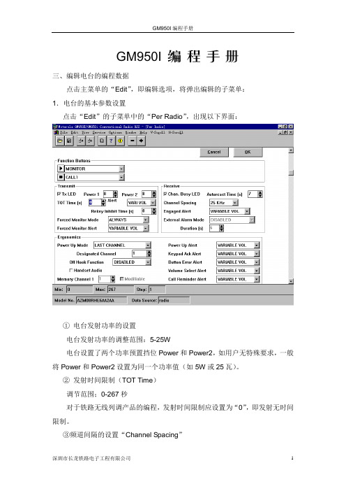
GM950I编程手册三、编辑电台的编程数据点击主菜单的“Edit”,即编辑选项,将弹出编辑的子菜单:1.电台的基本参数设置点击“Edit”的子菜单中的“Per Radio”,出现以下界面:①电台发射功率的设置电台发射功率的调整范围:5-25W电台设置了两个功率预置挡位Power和Power2,如用户无特殊要求,一般将Power和Power2设置为同一个功率值(如5W或25瓦)。
②发射时间限制(TOT Time)调节范围;0-267秒对于铁路无线列调产品的编程,发射时间限制应设置为“0”,即发射无时间限制。
③频道间隔的设置“Channel Spacing”规定频道间隔必须设置成25KHz。
④其它参数同出厂值。
参数设置完毕后,点击“OK”退到编程的主界面。
2.电台各频道收/发频率的设置点击“Edit”的子菜单中的“Per Channer”,出现以下界面:①设置电台对应频道的收/发频率,及发射功率;②其它选项同出厂值;③参数设置完毕后,点击“OK”退到编程的主界面。
3.增加电台的频道点击“Edit”的子菜单中的“Add Channer”,出现以下界面:点击“Add”将按照CH1的格式复制CH2频道,然后屏幕自动回到主菜单。
4.删除电台的频道点击“Edit”的子菜单中的“Delete Channer”,出现以下界面:选择要删除的频道,点击“Delete”,将完成删除,并自动回到主菜单。
5.电台各收/发频率列表清单点击“Edit”的子菜单中的“Overview”,出现以下界面:点击“OK”退出。
四、电台指标的调整点击主菜单的“Servise”,将弹出子菜单:共有“TX Alignments”和“Rx Alignments”两个选项1.电台发射指标的调整“TX Alignments”①供电电压上下限的设置“Bettery Thresholds”,见下图:上述两个值:11.5V及15V不应改变。
②功率的调整“RF Power”可以微调某一频段的高或低功率值的调整,用“Toggle PTT”用试验频率发射功率,用“Program”存储,并自动退到主菜单。
950-ME1机械驱动1学习系统说明书

The 950-ME1 Mechanical Drives 1 Learning System teaches fundamentals of mechanical
CURRICULUM
LearningTopics:
(16) -CoToolboxstorageshelf -Motorcontrolunitmounting -Casters,lockingtype(2)
PronyBrake
-TorqueRange,0-3.05N-M -Manualtorqueadjustment -Springgaugeforcereadout -Coolantspraybottle -Loaddrumwithcoolantchamber
•ChainandV-BeltDrives
onthejobandtowithstandfrequentstudentuse.
•FlexibleJawCouplings
•Pillow-BlockTypeBearings
Additionalpanelsarealsoavailabletoextendthelearningcapabilities
ConstantSpeedMotor
-Singlephase,capacitorstart -1/3Hprating;Nema56frame;1750RPM
AdjustableMotorBase
-Formedsteel,11gauge -Dualleadscrewadjustment -Traveladjustment,5.75in(146mm)
950用户手册
B E T A950用户手册武汉奥泰克仪器仪表有限公司1、产品简介BETA950是一种便携式、由电池供电的多功能过程校验仪,该设备可测量或模拟输出多种电信号和物理量。
BETA950具有如下功能及特点:1、具有双通道显示,显示屏上半部分的显示区域可显示电压、电流和压力的测量值,显示屏下半部分的显示区域可显示电压、电流、压力、热电阻、热电偶、频率和电阻的测量值,还可以模拟输出脉冲值。
2、热电偶输入输出端带有自动冷端温度补偿。
3、每个电信号或物理量的测量量程范围内均可设定5个递增或递减数值点。
4、互动式的使用菜单。
5、可使用自带的RS232接口进行远程控制。
6、独立的重复读数功能可校验变送器。
7、可进行开关测试。
1.1标准配置一套完整的BETA950应包括如下部分:BETA950主机,使用手册,测量导线套,橡胶外壳,NIST 证书。
1.2 安全事项请在使用BETA950时需注意以下几点:1、请勿超过额定电压,详见量程范围说明。
2、遵循一切设备安全条例。
3、当测量导线插在电流测量端时,请不要使测量头接触电压源。
4、如BETA950已损坏,请不要继续使用。
5、在使用前请检查仪器的外壳,查看是否有裂纹或缺口。
6、要特别注意连接导线的接头部位的绝缘材料是否完整。
7、测量时请选择正确的功能和量程。
8、使用前请确认电池仓的盖子是否已关严。
9、打开电池仓之前请将测量导线从BETA950上拔下。
10、检查测量导线的绝缘材料是否已经损坏或已有金属部分裸露在外,在使用BETA950前请将已坏的测量导线进行更换。
11、在使用测量导线的夹头时,手指部分请不要触摸夹头。
12、请勿非正常使用BETA950,这种行为可能会减少仪器的使用寿命。
13、在使用中如有疑问,请与我公司技术售后服务部门联系。
14、请不要在含有爆炸性气体、蒸汽或灰尘的环境中使用BETA950。
15、当外接压力模块时,请确保压力导管在连接或拆除时处于关闭和泄压状态。
写频软件说明

说明
1、G M300是MOTOROLA GM300、M120 150MHz及400MHz
车载台专用的写频软件。
于MS-DOS状态下操作。
操作路径如下:F(光盘或硬盘盘符):\MOTOROLA\GM300\GM300 回车
2、G M300A是MOTOROLA GM300、M120 350MHz车载台专用
的写频软件。
于MS-DOS状态下操作。
硬件要求为486及以下微机即可。
操作路径如下:
F(光盘或硬盘盘符):\MOTOROLA\GM300A\GM300A 回车
3、S M50是专用于MOTOROLA SM50车载台的写频软件。
操作命
令如下:
F(光盘或硬盘盘符):\MOTOROLA\SM50\MAIN 回车。
4、G P88是专用于MOTOROLA GP88、GP300对讲机的写频软件。
操作路径如下:
F(光盘或硬盘盘符):\MOTOROLA\GP88\P 回车GM950写频软件可用于MOTOROLA GM950e 、GM950i、GM950plus 车载台的写频。
在写频菜单中选择即可。
于WIN 9X 状态下操作。
5、G P88S写频软件是专用于MOTOROLA GP88S对讲机的写频软
件。
于WIN 9X 状态下操作。
6、G R1225是专用于MOTOROLA GR1225中转台的写频软件。
于
WIN 9X 状态下操作。
艾莫德 AS-950 无线个人监控系统说明书
AS-950The AS-950 is easy to use. The Any Spot ® WPM replaces floor wedges and the amplifiers that power them. Simply plug the ANY SPOT ® into a ‘monitor out’ jack on the mixing console, create the desired mix, and it’s ready to deliver quality sound. The AS-950 has 16 selectable UHF frequencies which can transmit in either mono or stereo.The AS-950R (receiver) features an 50mW x 2 headphone amplifier with a standard 3.5mm (1/8") headphone output. The LCD Display and Up/Down buttons make channel selecting an easy task. The AS-950R is sure to be plenty loud for any environment. The receiver has a built-in limiter.The AS-950T (transmitter) has two XLR/1/4" combo jacks for its inputs, stereo/mono switch & headphone output w/ volume control. The transmitter includes a single/dual rack mount kit, for mounting one unit in one rack space or mounting two transmitters side by side in one rack space.The Any Spot ® Series of Wireless Personal Monitors is a great alternative for performers who are tired of lugging around heavy and bulky floor monitors and tired of leaving a gig with ringing ears. The AS-950 allows the user to move freely around the stage and continue to hear the monitor mix.Band Pack SystemThe AS-950-4 Band Pack Systems makes it easy for any band to Get Personal . The system includes four receivers and one transmitter. It is designed to get the whole band wireless in one package. The AS-950-4 will allow a band to send one stereo mix to 4 individuals. Add as many additional receivers as needed.AS-950T16 Selectable UHF Frequencies● Send a Stereo or Mono Mix to Any Number of ● Receivers on StageEasy Setup Right Out of the Box ● XLR / 1/4 Combo Line Level Input ●" Easy to Read Audio LED Indicators ● Input Level Control● 1/4 Headphone Output with Volume Control for ●" Easy MonitoringAS-950RBuilt-in Limiter● ●Multi-function LCD DisplayUp and Down Channel Select Buttons● Operates on 2 AA Batteries (Alkaline or Rechargeable)● Lightweight Titanium Driver EB4 Ear Buds Included●®ANY SP TOWIRELESS PERSONAL MONITORSpecifications subject to change without notice.V20180823601 E. Pawnee Wichita, KS 67211 316. 263.2852 FAX 316.263.0642 Distributed in Canada by Audio Distributors International (ADI ) 1275 Newton, unit 6 Boucherville, QC J4B 5H2 Canada450.449.8177 FAX 450.449.8180AS-950Specifications:AS-950 System Band: UHFTransmitter Output Level: 10 mWOperating Range: Under Typical Conditions 200' (61m) Note: actual range depends on RF signal absorption, reflection, interference, and battery characteristics Audio Frequency Response: +/-3dB 50Hz~15kHz Total Harmonic Distortion: <1% @ 1kHz Signal to Noise: >80dBAMaximum Deviation Range: +/-40kHz Dynamic Range: >90dB A-weightedOperating Temperature Range: 14ºF to 122ºF (-10º C to +50º C) Note: battery characteristics may limit this rangeIncluded Accessories: Power Supply, EB4 Ear Buds, Antenna, Single/Dual Rack Ears, Quick Start GuideAS-950T TransmitterMain Frame Size: EIA STANDARD 1/2U Modulation Mode: FM Stereo Modulation RF Output: 10 mWMax Audio Input Level: +6dBV Gain Adjustment Range: 40dBControls: Headphone Volume, Channel Up/Down, and Power Button Audio Input: Line Level x 2, XLR/1/4" Combo Jack XLR Input: Impedance balanced Pin: 1 Ground (cable shield) Pin: 2 Audio + Pin: 3 No Audio -Dimensions: 1.73" x 8.34" x 3.77" (44 x 212 x 96 mm)(HxWxD)Weight: 19.75 oz (560 g)12-18 V DC at 300mA supplied by Power Supplied By:external power supplyAS-950R Body Pack Receiver Audio Output Level: 50mW x 2Sensitivity: -94dBm for 30dBStereo Separation: 40dB (at 1kHz)Output Connector: 1/8" (3.5mm) Stereo Earphone Connector Controls: Volume, Channel Up/DownIndicators: Multi-function LCD, LOW Battery, RF LED Dimensions: 3.54" x 2.51" x 0.9" (90 x 64 x 23 mm)(HxWxD)Weight: 3.35 oz (95 g) without batteries2 (AA) size alkaline or rechargeable batteries Power Supplied By:Battery Life: Up to 12 hours (alkaline)AS-950T T ransmitterBACK VIEWTOP VIEWAS-950R®ANY SP TO WIRELESS PERSONAL MONITOREB4 StandardEar BudsCODE N MH 518 - 542 z 470 - 489 CODE P2MHz。
摩托罗拉GM950_Control_Head维修手册

摩托罗拉GM950_Control_Head维修⼿册Table of ContentsChapter 4Control Heads/Control MicrophonesSpeci?c InformationT able of ContentsChapter Page 4A Control Head for Radio Model N2 ........................................................4A.1-i 4B Control Head for Radio Model N3.........................................................4B.1-i 4C Hand Held Control Microphone GMN6151...........................................4C.1-i 4D Control Head for Radio Model N4.........................................................4D.1-iControl Heads/Control Microphones Specific Information4-iTable of Contents4-ii Control Heads/Control Microphones Specific InformationTable of ContentsChapter 4BControl Head for Radio Model N3Table of ContentsChapter4B.1Introduction/Theory of Operation4B.2PCB/Schematic Diagram and Parts ListControl Head for Radio Model N34B-iTable of Contents4B-ii Control Head for Radio Model N3Table of ContentsChapter 4B.1Introduction/Theory of OperationT able of ContentsParagraph Page1.0Introduction (1)2.0Exploded View Diagram (1)3.0Theory of Operation (2)Introduction/Theory of Operation4B.1-iTable of Contents4B.1-ii Introduction/Theory of OperationThe features of the N3 radio control head are as follows: s On/Off Buttons Rocker Type Volume Up/Down Controls 3 digit, 7 segment Backlit LCD displays8 LCD Annunciators/Iconss 3 LEDs (Red, Y ellow, Green)s Up/Down keys for Channel Increment/Decrements 6 Dealer Programmable Option Buttonss Internal 4W LoudspeakerExploded View DiagramHousing incl.LCD Gasket1502612Y01LCD7202695Y01 (5 Tone)7202662Y01 (MPT /Conventional)Keypad7502615Y01 (MPT)7502615Y02 (Conventional)7502615Y04 (5 Tone)Printed Circuit Board 8402622Y_Speaker 5005156Z02 andGasket 3205932V01Frame LCD0702643Y01Connector Elastromeric2802638Y04 top2802638Y03 bottomGEPD5493Introduction/Theory of Operation4B.1-13.0Theory of Operation3.1GeneralThe Control Head contains the internal speaker, the microphone connector, several buttons to operate the radio, and several indicator Light Emitting Diodes (LED) to inform the user about the radio status.Additionally, the control head uses a 3 digit / 7 segment Liquid Crystal Display (LCD) for the numerical information e.g. channel number, select code.3.2Power SuppliesThe power supply to the Control Head is taken from the host radio’s FLT A+ voltage via connectorJ0901 pin 2 and the regulated +5V via connector J0901 pin 10. The voltage FLT A+ is at batterylevel and is used for the LEDs, the back light and to power up the radio via the On / Off button. The stabilized +5 volt is used for the display, the display driver, the shiftregister and the keypad buttons.3.3Power On / OffThe On/Off button when pressed switches the radio’s voltage regulators on by pulling ON OFFCONTROL to high via (D0925) and connects the base of (Q0925) to FLT A+. This transistor pulls the line ANALOG 3 to low to inform the µP that the On/Off button is pressed. If the radio is switched off, the µP will switch it on and vice versa. If theOn/Off button is pressed and held while the radio is on, the software detects a low state on line ANALOG 3 and switches the radio off.3.4Keypad KeysThe Control Head keypad is an (11) - key keypad. All keys are con?gured as 3 analogue lines(ANALOG 1 2 3) to the radio. Lines ANALOG 1,2 each control four keys; line ANALOG 3 controlsthree keys. The voltage on the analogue lines varies between 0V and +5V depending on which key has been pressed. If a button is pressed, it will connect one of the 3 lines ANALOG 1,2,3 to aresistive voltage divider connected to +5V. The voltages of the lines are A/D converted inside the µP and specify the pressed button.3.5Status LED and Back Light CircuitAll the indicator LEDs (4) and the back light LEDs (20) are driven by current sources (Q0942 -Q0944, Q0951, Q0952) and controlled by the µP via SERIAL PERIPHERAL INTERFACE (SPI). The current is determined by the resistor at the emitter of the respective current source transistor.Shiftregister (U0941) stores the LED status. T o update the LED status line LED CLCK BUF shifts the data of line SPI DA TA BUF into the shiftregister. When all the data has been written, line LED CE is set to low for a few microseconds to update the output of the shiftregister with the new data.4B.1-2Introduction/Theory of OperationTheory of Operation3.6Liquid Crystal Display (LCD)The LCD display H0931 is a 3 digit / 7 segment display which incorporates (11) annunciators. Data is loaded serially into the display driver U0932 via the SPI interface. The display data of line SPIDA TA BUF is shifted serially into the display driver by clock signal LCD CLCK BUF. When the last bit has been received, the LCD display is updated.3.7Microphone ConnectorSignals BUS+, PTT, HOOK VPP, MIC HI, HANDSET AUDIO from the microphone connector (J0903) are fed to the radio’s controller section via connector (J0901) .3.8SpeakerThe Control Head contains a speaker for the receiver audio. The receiver audio signal from thedifferential audio output of the audio ampli?er located on the radio’s controller is fed via lines INTSPKR+, INT SPKR-, connector (J0901-18,17) to the speaker connector (J0902) pin 1 and pin 2. The speaker is connected to the connector (J0902) .3.9Electrostatic Transient ProtectionElectrostatic transient protection is provided for the sensitive components in the Control Head bydiodes (VR0901 - VR0909). The diodes limit any transient voltages to tolerable levels. Theassociated capacitors provide Radio Frequency Interference (RFI) protection.3.10Reversible Control HeadThe control head is connected to the RF transceiver by means of a short ?exible ribbon cable. This allows the control head to be mounted either way up in relation to the body of the transceiver. Thismeans that the transceiver can be mounted in the most cosmetically pleasing and most ef?cientcooling orientation and still have the user interface the “right way” up.Introduction/Theory of Operation4B.1-34B.1-4Introduction/Theory of OperationTable of ContentsChapter 4B.2PCB/Schematic Diagram and Parts ListT able of ContentsDescription Page Control Head (N3) - Diagrams and Parts ListsPCB Layout Component Side . . . . . . . . . . . . . . . . . . . . . . . . . . . . . . . . . . . . . . . . . . . . .1 PCB Layout Solder Side . . . . . . . . . . . . . . . . . . . . . . . . . . . . . . . . . . . . . . . . . . . . . . . . .1 Schematic Diagram. . . . . . . . . . . . . . . . . . . . . . . . . . . . . . . . . . . . . . . . . . . . . . . . . . . . .3 Parts List . . . . . . . . . . . . . . . . . . . . . . . . . . . . . . . . . . . . . . . . . . . . . . . . . . . . . . . . . . . . .4PCB/Schematic Diagram and Parts List4B.2-iTable of Contents4B.2-ii PCB/Schematic Diagram and Parts ListControl Head (N3) PCB No. 8402622Y04_T2PCB No. 8402622Y04_T2 Diagrams and Parts List4B.2-1Control Head (N3) PCB No. 8402622Y04_T24B.2-2Diagrams and Parts ListControl Head (N3) Schematic DiagramDiagrams and Parts List4B.2-3Control Head (N3) Schematic Diagram4B.2-4Diagrams and Parts ListControl Head (N3)Parts ListCircuit RefMotorola Part No.DescriptionC0901*******F17470pF 50V C0902*******F17470pF 50V C0934*******K15100nF 16V C0935*******F4910nF 50VC0941*******K15100nF 16VC09422311049J23T ANT CP 10uF 10% 6V D09254813833C02DUAL SOT MMBD6100D0941*******G73LED SMT YELD09424805729G73LED SMT YEL D0943*******G74LED SMT RED D09444805729G75LED SMT GREEN D0951-D09704805729G75LED SMT GREEN H0931*******Y01CNTL K DISPLAY J0901*******Y01CONN FLEX Side EntryJ0902*******G01CONN 1.25MM CTR SUR J0903*******V01CONNECTOR MIC Q09254880048M01NPN DIG 47k/47kQ0931*******M16PNP SOT MMBT3906Q0941*******M01NPN DIG 47k/47k Q09424813824A10NPN 40V .2A B=50-150Q0943*******A10NPN 40V .2A B=50-150Q09444813824A10NPN 40V .2A B=50-150Q0951*******A10NPN 40V .2AB=50-150Q0952*******A20R0901*******A35270 5 1/8R0902*******A491k 1/16W 5%R0911-R09220662057A654k7 1/16W5%R09250662057A654k7 1/16W 5%R09260662057A654k7 1/16W 5%R09310662057A654k7 1/16W 5%R09320662057A7310k 1/16W 5%R0933*******A97100k 1/16W R0941*******A7310k 1/16W 5%R09420662057A8947k 1/16W5%R0943*******A8947k 1/16W 5%R09440660076A35270 5 1/8R09450662057A8947k 1/16W 5%R09460662057A41470 1/16W 5%R09470662057A8947k 1/16W 5%R09480660076A35270 5 1/8R0952*******A8020k 1/16W5%R0953*******A7310k 1/16W 5%R0954*******M0110 1W 5%U0932*******U61LCD DRIVER33 SEGMENT ST A TIC U0941*******A35MC14094, REG,8-ST AGE,SHIFT/STOREU VR0901*******A14 5.1V 5% 225mW VR0902*******A14 5.1V 5% 225mW VR0903*******A2714V 5% 225mW VR09044813830A2714V 5% 225mW VR09054813830A2714V 5% 225mW VR0906*******A14 5.1V 5% 225mW VR09074813830A14 5.1V 5% 225mW VR09084813830A145.1V 5% 225mWCircuit RefMotorola Part No.Description。
GM使用手册

LED
¥ LCD
Msg Received
Message #_ No Alias
¥
E
ÐÐ
¥
E(
)
ÐÐ
¥ )
E (
¥ ¥ ¥
20
(
6-7 ).
¥ ¥ ¥
K
Radio Disabled
ID ID
1u 2 yz
3u 4 yz
5u 6 yz
7u 8 yz 9u
10
11 u
Program Lists Program Lists RadioCall List RadioCall List Edit Entry? Edit Entry?
18
7
PTT
8
9t
ÐÐ
t
Call In Prog
Acknowledge No Acknowledge Radio Check
14
1u 2 yz
Status
3u 4 yz
ÐÐ
ÐÐ 6-7 )
Status (
14
1u 2 yz
3u 4 yz
ÐÐ
ÐÐ 6-7 )
Message Message
(
19
¥
¥
5u 6 yz
ID ÐÐ
ID
7
PTT
Radio Call
8
PTT
9
t
ÐÐ
t
Selective Call
Radio Call Selective Call
Selective Call
¥ ¥ LED ¥ LCD
F
ID
16
PAGE)
(CALL ALERTª
摩托罗拉GM950_Control_Head维修手册

Table of ContentsChapter 4Control Heads/Control MicrophonesSpecific InformationT able of ContentsChapter Page 4A Control Head for Radio Model N2 ........................................................4A.1-i 4B Control Head for Radio Model N3.........................................................4B.1-i 4C Hand Held Control Microphone GMN6151...........................................4C.1-i 4D Control Head for Radio Model N4.........................................................4D.1-iControl Heads/Control Microphones Specific Information4-iTable of Contents4-ii Control Heads/Control Microphones Specific InformationTable of ContentsChapter 4BControl Head for Radio Model N3Table of ContentsChapter4B.1Introduction/Theory of Operation4B.2PCB/Schematic Diagram and Parts ListControl Head for Radio Model N34B-iTable of Contents4B-ii Control Head for Radio Model N3Table of ContentsChapter 4B.1Introduction/Theory of OperationT able of ContentsParagraph Page1.0Introduction (1)2.0Exploded View Diagram (1)3.0Theory of Operation (2)Introduction/Theory of Operation4B.1-iTable of Contents4B.1-ii Introduction/Theory of OperationThe features of the N3 radio control head are as follows: s On/Off Buttons Rocker Type Volume Up/Down Controls 3 digit, 7 segment Backlit LCD displays8 LCD Annunciators/Iconss 3 LEDs (Red, Y ellow, Green)s Up/Down keys for Channel Increment/Decrements 6 Dealer Programmable Option Buttonss Internal 4W LoudspeakerExploded View DiagramHousing incl.LCD Gasket1502612Y01LCD7202695Y01 (5 Tone)7202662Y01 (MPT /Conventional)Keypad7502615Y01 (MPT)7502615Y02 (Conventional)7502615Y04 (5 Tone)Printed Circuit Board 8402622Y_Speaker 5005156Z02 andGasket 3205932V01Frame LCD0702643Y01Connector Elastromeric2802638Y04 top2802638Y03 bottomGEPD5493Introduction/Theory of Operation4B.1-13.0Theory of Operation3.1GeneralThe Control Head contains the internal speaker, the microphone connector, several buttons tooperate the radio, and several indicator Light Emitting Diodes (LED) to inform the user about theradio status.Additionally, the control head uses a 3 digit / 7 segment Liquid Crystal Display (LCD) for thenumerical information e.g. channel number, select code.3.2Power SuppliesThe power supply to the Control Head is taken from the host radio’s FLT A+ voltage via connectorJ0901 pin 2 and the regulated +5V via connector J0901 pin 10. The voltage FLT A+ is at batterylevel and is used for the LEDs, the back light and to power up the radio via the On / Off button. The stabilized +5 volt is used for the display, the display driver, the shiftregister and the keypad buttons.3.3Power On / OffThe On/Off button when pressed switches the radio’s voltage regulators on by pulling ON OFFCONTROL to high via (D0925) and connects the base of (Q0925) to FLT A+. This transistor pulls the line ANALOG 3 to low to inform the µP that the On/Off button is pressed. If the radio is switched off, the µP will switch it on and vice versa. If the On/Off button is pressed and held while the radio is on, the software detects a low state on line ANALOG 3 and switches the radio off.3.4Keypad KeysThe Control Head keypad is an (11) - key keypad. All keys are configured as 3 analogue lines(ANALOG 1 2 3) to the radio. Lines ANALOG 1,2 each control four keys; line ANALOG 3 controlsthree keys. The voltage on the analogue lines varies between 0V and +5V depending on which key has been pressed. If a button is pressed, it will connect one of the 3 lines ANALOG 1,2,3 to aresistive voltage divider connected to +5V. The voltages of the lines are A/D converted inside the µP and specify the pressed button.3.5Status LED and Back Light CircuitAll the indicator LEDs (4) and the back light LEDs (20) are driven by current sources (Q0942 -Q0944, Q0951, Q0952) and controlled by the µP via SERIAL PERIPHERAL INTERFACE (SPI). The current is determined by the resistor at the emitter of the respective current source transistor.Shiftregister (U0941) stores the LED status. T o update the LED status line LED CLCK BUF shifts the data of line SPI DA TA BUF into the shiftregister. When all the data has been written, line LED CE is set to low for a few microseconds to update the output of the shiftregister with the new data.4B.1-2Introduction/Theory of OperationTheory of Operation3.6Liquid Crystal Display (LCD)The LCD display H0931 is a 3 digit / 7 segment display which incorporates (11) annunciators. Data is loaded serially into the display driver U0932 via the SPI interface. The display data of line SPIDA TA BUF is shifted serially into the display driver by clock signal LCD CLCK BUF. When the last bit has been received, the LCD display is updated.3.7Microphone ConnectorSignals BUS+, PTT, HOOK VPP, MIC HI, HANDSET AUDIO from the microphone connector (J0903) are fed to the radio’s controller section via connector (J0901) .3.8SpeakerThe Control Head contains a speaker for the receiver audio. The receiver audio signal from thedifferential audio output of the audio amplifier located on the radio’s controller is fed via lines INTSPKR+, INT SPKR-, connector (J0901-18,17) to the speaker connector (J0902) pin 1 and pin 2. The speaker is connected to the connector (J0902) .3.9Electrostatic Transient ProtectionElectrostatic transient protection is provided for the sensitive components in the Control Head bydiodes (VR0901 - VR0909). The diodes limit any transient voltages to tolerable levels. Theassociated capacitors provide Radio Frequency Interference (RFI) protection.3.10Reversible Control HeadThe control head is connected to the RF transceiver by means of a short flexible ribbon cable. This allows the control head to be mounted either way up in relation to the body of the transceiver. Thismeans that the transceiver can be mounted in the most cosmetically pleasing and most efficientcooling orientation and still have the user interface the “right way” up.Introduction/Theory of Operation4B.1-34B.1-4Introduction/Theory of OperationTable of ContentsChapter 4B.2PCB/Schematic Diagram and Parts ListT able of ContentsDescription Page Control Head (N3) - Diagrams and Parts ListsPCB Layout Component Side . . . . . . . . . . . . . . . . . . . . . . . . . . . . . . . . . . . . . . . . . . . . .1 PCB Layout Solder Side . . . . . . . . . . . . . . . . . . . . . . . . . . . . . . . . . . . . . . . . . . . . . . . . .1 Schematic Diagram. . . . . . . . . . . . . . . . . . . . . . . . . . . . . . . . . . . . . . . . . . . . . . . . . . . . .3 Parts List . . . . . . . . . . . . . . . . . . . . . . . . . . . . . . . . . . . . . . . . . . . . . . . . . . . . . . . . . . . . .4PCB/Schematic Diagram and Parts List4B.2-iTable of Contents4B.2-ii PCB/Schematic Diagram and Parts ListControl Head (N3) PCB No. 8402622Y04_T2PCB No. 8402622Y04_T2 Diagrams and Parts List4B.2-1Control Head (N3) PCB No. 8402622Y04_T24B.2-2Diagrams and Parts ListControl Head (N3) Schematic DiagramDiagrams and Parts List4B.2-3Control Head (N3) Schematic Diagram4B.2-4Diagrams and Parts ListControl Head (N3)Parts ListCircuit RefMotorola Part No.DescriptionC0901*******F17470pF 50V C0902*******F17470pF 50V C0934*******K15100nF 16V C0935*******F4910nF 50V C0941*******K15100nF 16VC09422311049J23T ANT CP 10uF 10% 6V D09254813833C02DUAL SOT MMBD6100D0941*******G73LED SMT YEL D09424805729G73LED SMT YEL D0943*******G74LED SMT RED D09444805729G75LED SMT GREEN D0951-D09704805729G75LED SMT GREEN H0931*******Y01CNTL K DISPLAY J0901*******Y01CONN FLEX Side Entry J0902*******G01CONN 1.25MM CTR SUR J0903*******V01CONNECTOR MIC Q09254880048M01NPN DIG 47k/47k Q0931*******M16PNP SOT MMBT3906Q0941*******M01NPN DIG 47k/47k Q09424813824A10NPN 40V .2A B=50-150Q0943*******A10NPN 40V .2A B=50-150Q09444813824A10NPN 40V .2A B=50-150Q0951*******A10NPN 40V .2A B=50-150Q0952*******A20R0901*******A35270 5 1/8R0902*******A491k 1/16W 5%R0911-R09220662057A654k7 1/16W 5%R09250662057A654k7 1/16W 5%R09260662057A654k7 1/16W 5%R09310662057A654k7 1/16W 5%R09320662057A7310k 1/16W 5%R0933*******A97100k 1/16W R0941*******A7310k 1/16W 5%R09420662057A8947k 1/16W 5%R0943*******A8947k 1/16W 5%R09440660076A35270 5 1/8R09450662057A8947k 1/16W 5%R09460662057A41470 1/16W 5%R09470662057A8947k 1/16W 5%R09480660076A35270 5 1/8R0952*******A8020k 1/16W 5%R0953*******A7310k 1/16W 5%R0954*******M0110 1W 5%U0932*******U61LCD DRIVER33 SEGMENT ST A TIC U0941*******A35MC14094, REG,8-ST AGE,SHIFT/STOREU VR0901*******A14 5.1V 5% 225mW VR0902*******A14 5.1V 5% 225mW VR0903*******A2714V 5% 225mW VR09044813830A2714V 5% 225mW VR09054813830A2714V 5% 225mW VR0906*******A14 5.1V 5% 225mW VR09074813830A14 5.1V 5% 225mW VR09084813830A145.1V 5% 225mWCircuit RefMotorola Part No.Description。
Gm软件用户指南说明书

Package‘gm’October13,2022Type PackageTitle Generate Music Easily and Show Them AnywhereVersion1.0.2Author Renfei MaoMaintainer Renfei Mao<*******************>Description Provides a simple and intuitive high-level language,with which you can create music easily.Takes care of all the dirty technicaldetails in converting your music to musical scores and audiofiles.Works in'R Markdown'documents<https:///>, R'Jupyter Notebooks'<https:///>,and'RStudio'<https:///>,so you can embed generated musicanywhere.Internally,uses'MusicXML'<https:///>to represent musical scores,and'MuseScore'<https:///>to convert'MusicXML'.License MIT+file LICENSEURL https:///flujoo/gm,https://flujoo.github.io/gm/ Encoding UTF-8RoxygenNote7.1.1Suggests rmarkdown,testthatImports base64enc,glue,htmltools,knitr,magick,magrittr,MASS, rlang,rstudioapi,stringr,utilsVignetteBuilder knitrSystemRequirements MuseScore-https:/// NeedsCompilation noRepository CRANDate/Publication2021-04-1705:40:02UTC12+.Music R topics documented:+.Music (2)Clef (3)export (4)gm (5)inspect_errors (5)Key (6)Line (7)Meter (9)Music (10)show (11)Tempo (12)Tupler (13)tuplet (14)Index15 +.Music Add Component to Music ObjectDescriptionAdd a component to a Music object.Usage##S3method for class Musicmusic+termArgumentsmusic A Music object.term A Line,Meter,Key,Clef or Tempo object.ValueA list with class Music.See AlsoMusic()for initializing a Music object.Line(),Meter(),Key(),Clef()and Tempo()for creating objects of corresponding classes.Clef3Examples#initialize a Music objectm<-Music()#add a Line objectm<-m+Line(list("C4"),list(1))m#add a Meter objectm<-m+Meter(4,4)m#add a Key objectm<-m+Key(1)m#add a Clef objectm<-m+Clef("G",to=1)m#add a Tempo objectm<-m+Tempo(120)mClef Create Clef ObjectDescriptionCreate a Clef object.Clef objects represent clefs.UsageClef(sign,line=NULL,octave=NULL,to=NULL,bar=NULL,offset=NULL) Argumentssign"G","F"or"C",case insensitive.line Optional,1or2if sign is"G",an integer between3and5if sign is"F",or an integer between1and5if sign is"C".octave Optional,-1or1.octave can be specified only when sign is"G"and line is 2,or sign is"F"and line is4.to an index or a Line name,which indicates to which Line object to add the Clef object.bar Optional.A positive integer which indicates the number of the measure to which to add the Clef object.By default,a Clef object will be added to thefirstmeasure.4export offset Optional.A duration value,sum of duration values or0,which indicates the position in a measure,at which to add the Clef object.The default value is0.ValueA list with class Clef.See Also+.Music()for adding Clef objects to a Music object.vignette("gm",package="gm")for details about duration values.Examples#create a Clef objectClef("G",line=2,octave=1)#add a Clef object to a Music objectMusic()+Line(list("C4"),list(1))+Clef("F",to=1,bar=10,offset=1)export Export ObjectDescriptionExport an object to variousfile formats.Usageexport(x,dir_path,file_name,formats)##S3method for class Musicexport(x,dir_path,file_name,formats)Argumentsx An object.dir_path A single character which specifies the directory to which to export the object.file_name A single character which specifies the name of the exportedfile(s).formats A character vector which specifies thefile formats.Supportedfile formats are"mscz","mscx","pdf","png","svg","wav","mp3","flac","ogg","midi","mid","musicxml","mxl","xml","metajson","mlog","mpos"and"spos".gm5ValueInvisible NULL.Files with name file_name and with extensions formats are generated in dir_path.Methods(by class)•Music:export a Music object.Examplesif(interactive()){m<-Music()+Meter(4,4)+Line(list("C4"),list(4))export(m,tempdir(),"x",c("mp3","png"))}gm gm:Generate Music Easily and Show Them AnywhereDescriptionProvides a simple and intuitive high-level language,with which you can create music easily.Takes care of all the dirty technical details in converting your music to musical scores and audiofiles.Works in R Markdown documents,R Jupyter Notebooks and RStudio,so you can embed generated music anywhere.AuthorRenfei Mao*******************inspect_errors See Full Error ReportDescriptionSee a full error report when the error message is too long and thus shortened.Usageinspect_errors()ValueInvisible NULL.The full error report is printed in console.6Key Examples##Not run:Line(list(c,"p",NULL,1:3,TRUE,NA_character_))##End(Not run)Key Create Key ObjectDescriptionCreate a Key object.Key objects represent key signatures.UsageKey(key,bar=NULL,to=NULL,scope=NULL)Argumentskey An integer between-7and7,which indicates the number offlat or sharp symbols in the key signature.bar Optional.A positive integer which indicates the number of the measure into which to insert the Key object.By default,a Key object will be inserted into thefirst measure(s).to Optional.A positive integer or a single character which indicates the Line object to which to add the Key object.By default,a Key object will be added to a wholeMusic object rather than to any specific Line object.scope Optional."part"or"staff",which indicates whether to add the Key object toa whole part or only to a staff of a part,if the argument to is specified,or thisargument will be ignored.The default value is"part".ValueA list with class Key.See Also+.Music()for adding Key objects to a Music object.Line7Examples#create a Key objectKey(-7)#insert a Key object into a specific measureMusic()+Key(7,bar=2)m<-Music()+Line(list("E5"),list(1),name="a")+Line(list("C4"),list(1),name="b",as="staff")#add a Key to a partm+Key(2,to="b")#add a Key to a staffm+Key(2,to="b",scope="staff")Line Create Line ObjectDescriptionCreate a Line object.Line objects represent musical lines.UsageLine(pitches,durations,tie=NULL,name=NULL,as=NULL,to=NULL,after=NULL,bar=NULL,offset=NULL)Argumentspitches A list whose members are1.single pitch notations,like"C4",to represent the pitch contents of notes,2.single MIDI note numbers,like60or"60",also to represent the pitch con-tents of notes,3.single NA s to represent the pitch contents of rests,or8Line4.vectors of pitch notations and MIDI note numbers,like c("C4","61"),torepresent the pitch contents of chords.durations A list whose members are1.single duration notations or their abbreviations,like"quarter"or just"q",2.single duration values,like1,which is equivalent to"quarter",or3.Duration objects returned by tuplet(),which is used to create complextuplets.tie Optional.A list of indices of argument pitches,which indicates at which posi-tions to add ties.name Optional.A single character to name the Line object.as Optional."part","staff"or"voice",to specify the state of the Line object.The default value is"part".to Optional.An index or a Line name,which indicates with which Line object as the reference to add the Line object.after Optional.A single logical which indicates whether to add the Line object after or before a reference Line object.The default value is TRUE.bar Optional.A positive integer which indicates the number of the measure to which to insert the Line object.By default,a Line object will be inserted to thefirstmeasure.offset Optional.A duration value,sum of duration values or0,which indicates the position in a measure,at which to insert the Line object.The default value is0.ValueA list with class Line.See Also+.Music()for adding Line objects to a Music object.vignette("gm",package="gm")for more details about Line objects.Examples#create a Music objectm<-Music()+Meter(4,4)+Line(list("C4"),list(8),name="a")#create a Line objectl<-Line(pitches=list("C5","C5","C5"),durations=list(1,1,1),#tie the first two notestie=list(1),#add the Line as a voiceas="voice",Meter9 #with Line"a"as referenceto="a",#before Line"a"after=FALSE,#insert the Line to bar2with offset1bar=2,offset=1)l#add the Line object to the Music objectm<-m+lmif(interactive()){show(m)}Meter Create Meter ObjectDescriptionCreate a Meter object.Meter objects represent time signatures.UsageMeter(number,unit,bar=NULL,actual_number=NULL,actual_unit=NULL,invisible=NULL)Argumentsnumber A positive number to represent the upper numeral in a time signature symbol, which indicates how many beats are contained in each measure.unit1,2,4,8,16,32or64to represent the lower numeral in a time signature symbol, which indicates the duration of one beat.bar Optional.A positive integer which indicates the number of the measure into which to insert the Meter object.By default,a Meter object will be insertedinto thefirst measure(s).10Music actual_number,actual_unitOptional,which defines the actual time signature rather than the time signaturesymbol on ually used to create pickup measures.By default,these twoarguments are the same with number and unit respectively.invisible Optional.A single logical,which indicates whether to show the time signature symbol on score.The default value is FALSE.ValueA list with class Meter.See Also+.Music()for adding Meter objects to a Music object.Examples#create a3/4time signatureMeter(3,4)#insert a time signature into a specific measureMusic()+Meter(3,4,bar=10)m<-Music()+Line(list("C5"),list(3))#specify the actual time signaturets<-Meter(3,4,actual_number=1,actual_unit=4)tsif(interactive()){show(m+ts)}#make a time signature invisible on scoreif(interactive()){ts<-Meter(3,4,invisible=TRUE)show(m+ts)}Music Initialize Music ObjectDescriptionInitialize a Music object.Music objects represent whole music pieces.UsageMusic()show11DetailsA typical workflow with Music objects:1.Initialize an empty Music object with Music().2.Add components to it with+.Music().3.Print it,or display it as musical score or audiofile with show(),to check its structure.4.Keep adding components and checking it until you get what you want.5.Sometimes you may want to export thefinal Music object with export().ValueA list with class Music.See Also+.Music()for adding components to a Music object.show()for displaying a Music object as musical score and audiofile.export()for exporting a Music object to variousfile formats.Examples#initialize a Music objectMusic()#print a Music object to check its structurem<-Music()+Meter(4,4)+Line(list("C4"),list(4))mshow Show ObjectDescriptionShow an object as musical score or audiofile.Usageshow(x,to)##S3method for class Musicshow(x,to=NULL)Argumentsx An object.to Optional.A character vector which contains"score","audio"or both,which indicates whether to show the object as musical score or audiofile.The defaultvalue is"score".12TempoValueInvisible NULL.The generated musical score or audiofile is1.showed in Viewer panel if show is called in RStudio,2.included in generated HTMLfile if called in R Markdown document,3.showed in output cell if called in R Jupyter Notebook,and4.showed in user’s browser if called in a normal R console.Methods(by class)•Music:show a Music object.Examplesif(interactive()){m<-Music()+Meter(4,4)+Line(list("C4"),list(4))show(m,c("score","audio"))}Tempo Create Tempo ObjectDescriptionCreate a Tempo object.Tempo objects represent tempo marks.UsageTempo(tempo,unit=NULL,bar=NULL,offset=NULL)Argumentstempo A number between5and999which indicates how many quarter notes per minute the tempo is.unit Optional.A duration notation,its abbreviation,or duration value corresponding to"whole","half","quarter","eighth","16th",with or without a dot.The defaultunit is"quarter".bar Optional.A positive integer which indicates the number of the measure at which to add the Tempo object.By default,a Tempo object will be added at thefirstmeasure.offset Optional.A duration value,sum of duration values or0,which indicates the position in a measure,at which to add the Tempo object.The default value is0.Tupler13ValueA list with class Tempo.See Also+.Music()for adding Tempo objects to a Music object.vignette("gm",package="gm")for details about duration notations and duration values.Examples#create a Tempo objectTempo(200)#set unit in a Tempo objectTempo(120,unit="half.")#add Tempo objects to a Music objectMusic()+Tempo(200)+Tempo(100,bar=10,offset=1)Tupler Create Tupler ObjectDescriptionCreate a Tupler object.Tupler objects are used in tuplet()to create tuplets.UsageTupler(n,unit=NULL,take=unit)Argumentsn A positive integer which indicates into how many parts to divide a duration.unit,take A duration type followed by zero to four dots,or its corresponding duration value.ValueA list with class Tupler.See Alsotuplet()vignette("gm",package="gm")for a friendly guide to tuplets.14tupletExamples#create a triplet quarter notet<-Tupler(3,unit="quarter",take="quarter")ttuplet("half",t)tuplet Create TupletDescriptionCreate a tuplet.Usagetuplet(duration,...)Argumentsduration A duration notation,duration value,or Duration object....Tupler objects returned by Tupler(),which specify how to divide the argument duration into parts,and how to take from these parts.ValueA list with class Duration.See AlsoTupler()vignette("gm",package="gm")for a friendly guide to tuplets.Examples#create a triplet quarter notetuplet("half",Tupler(3,unit="quarter",take="quarter"))Index+.Music,2+.Music(),4,6,8,10,11,13Clef,3Clef(),2export,4export(),11gm,5inspect_errors,5Key,6Key(),2Line,7Line(),2Meter,9Meter(),2Music,10Music(),2,11show,11show(),11Tempo,12Tempo(),2Tupler,13Tupler(),14tuplet,14tuplet(),1315。
GM338说明书

篇一:长沙基站台说明长沙无线基站通信系统说明1.系统介绍整个无线通信系统包括1异频中转设备摩托罗拉gr3188b,双工器,天馈线系统。
摩托罗拉gp338(摩托罗拉cp1660)对讲机及摩托罗拉无线调频基地台gf338等组成。
系统投资少,实施快,运用技术成熟,性能完善并预留扩展接口,升级扩容简单方便。
3.1.中转台摩拖罗拉gr3188b:由摩托罗拉gm3188等设备组装搭建而成的新一代中继台,内部结构设计更加优良,性能可靠稳定,可内置8组工作频率,具有功能扩展接口。
.19英寸标准机柜设计,便于系统机柜安装,也可以台式使用。
.优良的射频辐射性能体现了gm3188最为可靠的一面.内置交直流稳压电源和散热风扇.内置双工器双工工作,兼容同频工作 .无线多基站互控功能.录音接口实现计算机数字录音.遥控功能:无线遥控中转开启/关闭,中继延时0-15秒可调主要性能指标如下:频率范围:146-174mhz 403-470mhz信道数:8ch工作温度范围:-30 ℃to +60 ℃天线阻抗:50ωn型或n型重量:12kg 电源:13.8v dc 220v ac 频道间隔12.5/25 khz(vhf)尺寸:132(高)×485(宽)×285(长)mm音频输出功率:3w(内部扬声器)13w(外部扬声器)最大频率偏移:±5.0khz(25khz);±2.5khz(12.5khz)音频失真:1khz,60%频偏时<3%灵敏度:<0.35μv(12.5);<0.35μv(25)静噪灵敏度:-4db μv typ.(emf.threshold)杂波抑制:75db互调:67db typ.输出功率:25 ~40w频率稳定性±2.5 ppm(vhf);±2 ppm(uhf)计算机调整的项目:接收频率、发射频率、发射频偏、接收输出电平、输出功率等3.2.摩托罗拉手持对讲机 gp338 简介128信道频率范围是136-174mhz/403-470mhz 标配pmnn4008ar高容量氢电,智能充电器,通过ip54防雨实验,符合美国军标。
捷麦 T10L 无线电台信道编程手册说明书

--V1.2T10L 无线PLCDESCRIPITION OF PRODUCTSF0020E北京捷麦顺驰科技有限公司 ***************目录1.无线数传电台信道概述 (4)1.1 基本工作原理 (4)1.2 频率与频点 (4)1.3 电台地址寻址方式 (4)2.参数设置和编程连接 (6)2.1 参数说明 (6)2.2 设置操作 (7)2.3 编程连接 (8)2.4 工程下载 (8)3.编程操作 (11)3.1 信道初始化 (11)3.2 接收 (13)3.2.1 包结构 (13)3.2.2 用户接收处理 (13)3.2.3 电台接收完成事件 (14)3.2.4 相关系统变量/函数清单 (17)3.2.5 示例 (17)3.3 发送 (19)3.3.1 电台广播式发送字符串 (20)3.3.2 电台广播式发送数据块 (21)3.3.3 电台指定式发送字符串 (22)3.3.4 电台指定式发送数据块 (23)4.辅助功能 (25)4.1 无线电接收信号强度指示RSSI (25)4.2 电台信道通信测试 (27)24.2.1 回传测试01 (28)4.2.2 响应测试02 (31)4.2.3 请求发送1010 03 (32)4.2.4 测试接收信号强度04 (32)4.2.5 测试周围环境干扰信号强度05 (33)5.附录 (34)5.1 系统变量清单 (34)5.2 电台信道相关系统函数清单 (37)5.3 SM寄存器清单 (38)5.4 电台无线信道指令盒清单 (41)5.5 中断事件编号表 (43)5.6 透传电台编程实例 (44)5.6.1 C语言 (44)5.6.1 梯形图 (45)5.6.1 STL (46)5.7 产品家族介绍 (47)5.8 相关文档及阅读指南 (49)5.9 版权声明 (50)5.10 免责声明 (50)5.11 技术支持 (50)5.12 变更历程 (51)31. 无线数传电台信道概述T10L无线PLC内部集成了430M无线数传电台通信信道。
GM950E说明书

一、所需硬件设备1. IBM PC 386 DX33 或以上或兼容机,8 兆以上内存,10 兆以上硬盘空闲空间,3.5 寸软盘驱动器。
2. WINDOWS3.1/95/98/ME 操作系统3. 电台编程接口(RIB)RLN4008B4. 电台编程接口至计算机连接电缆3080369B71/725. 电台编程接口电源EPN4040A/EPN4041A EPN4041A(交流220V)或9V 叠层电池。
6. 电台编程接口至电台编程测试电缆GTF374A7. 电台电源GPN6133A 或其它12 伏10 安培输出电源二、硬件设备连接1. 通过计算机连接电缆3080369B71/72 将电台编程接口RLN4008B 和计算机串行通信口相连。
要弄清连接的计算机串口是第几个口(COM1,COM2…),在运行RSS 编程软件时,在Configuration 对话框中选择该串口,如果不清楚,请查阅计算机使用说明书。
2. 将电台编程测试电缆GTF374A 的25针插头连接到电台编程接口的插座上,然后将另一端的RJ45 插头插入电台麦克连接插座上。
3. 将电台编程接口电源EPN4040A/EPN4041A 输出连接到将电台编程接口,将交流电源线插到电源插座上。
将电台编程接口电源开关打开,发光二极管点亮。
也可以用9 V 叠层电池给电台编程接口供电。
4. 将电台电源线连接到电台电源GPN6133A 或其它12 伏10 安培的电源输出上,打开电台电源开关,再打开车台电源开关。
三、RSS 编程软件安装1. 将RSS 编程软件安装软盘插入软驱。
2. 运行A:盘上的SETUP.EXE 文件。
3. 当RSS 编程安装软件提示时,输入详细信息:- Destination 软件安装目录- Group Name of the Program Group 程序组组名- ComPort 1-4? 计算机串行通信口选择,应根据实际连接设定- Language 语音- User Name 用户名- Company Name 公司名4. 安装软件会检测软件安装目录里是否已经安装过RSS编程软件,如果已经安装过,安装程序会提示用户是否需要覆盖原来的编程软件。
GM950I说明书
安全信息安全及一般信息安全和有效操作的重要信息.在使用您的双向对讲机之前,请阅读下列信息。
本文提供的信息是取代2000年10月份前出版的用户手册,其中有关—般安全信息的内容。
对于在危险环境范围里使用对讲机的安全信息,请参阅厂际公约许可手册补充或指示卡,该信息包含在提供这些性能的对讲机型号中。
对讲机射频能量的操作按下通话键传输信息(讲话);释放通话键接收信息(接听)当对讲饥传输信息时,将产生对讲机射频能量;当对讲机接收信息时或关机时,不会产生对讲机射频能量:对讲机的操作及电磁能量的暴露您的摩托罗拉对讲饥在设计过程中严格遵照了下列国家和国际的标准和原则。
这些标准和原则用以保护暴露在射频电磁能量下工作人员的人身安全:1 美国联邦通信委员会,联邦管理条例;47cfr第2部分的j部分2 美国国家标准委员会(ansl)/电器和电子工程帅协会(1eee)c95.1-19923 电器和电子工程师协会(1eee)c95.1-1999版4 美国国家辐射保护和测量委员会(ncrp)报告86,19 865 国际非电离辐射保护委员(1cnirp)19986 加拿大卫生部安全条例6:人体暴露在频率范围从3 khz到300ghz的对讲机频率电磁场中的限制,1999澳大利亚通信特许对讲机通信(电磁辐射-暴露于人体)标准1999 (仅适用于无线电话)为确保对讲机的最佳性能,并确保人员暴露在对讲机的频率电磁能量是根据上述规定标准之内,请您务必遵守下列操作程序:便携式对讲机操作当您使用对讲机时,将对讲机垂直,麦克风对准嘴部距离1到2英寸(2.5到5厘米)。
身体佩戴操作为保证符合美国联邦通信委员会(fcc)射频(rf)暴露的有关规定,如果您在身上鼠带—部正在发射的对讲机,请您务必将对讲机放置在摩托罗拉提供或认可的夹子,机座、皮套、容器或全套身体装备.使用非摩托罗拉许可的附件可能造成超过美国联邦通信委员会(fcc)射频(rf)暴霹的有关规定,如果您不使用摩托罗拉认可的身体佩带附件,同时正确的使用对讲机,例如:对游扔处在电话模式盹不将对讲机放在耳朵的正常使用位置处在双向无线电对讲机模式时,不将对讲机手持于脸部前,请您在发射时,确保对讲机天线与人体至少有根据以下的距离:电话模式或双向对讲机模式时:1英寸(2.5匣米)使用任何一个数据性能与附件电缆:1英寸(2.5厘米)对子天线的保护仅使用提供或者被认可的替代天线.未许可的天线,修改或附件可能毁坏对讲机,并且可能违反美国联邦通信委员会(fcc)的规定,当对讲帆处在"inuse"(使用中九切勿触摸它的电线。
- 1、下载文档前请自行甄别文档内容的完整性,平台不提供额外的编辑、内容补充、找答案等附加服务。
- 2、"仅部分预览"的文档,不可在线预览部分如存在完整性等问题,可反馈申请退款(可完整预览的文档不适用该条件!)。
- 3、如文档侵犯您的权益,请联系客服反馈,我们会尽快为您处理(人工客服工作时间:9:00-18:30)。
GM950E/I 电台编程手册一、所需硬件设备1 . IBM PC 386 DX33 或以上或兼容机,8 兆以上内存,10 兆以上硬盘空闲空间,3.5 寸软盘驱动器。
2. WINDOWS3.1/95/98/ME 操作系统3. 电台编程接口(RIB)RLN4008B4. 电台编程接口至计算机连接电缆3080369B715. 电台编程接口电源EPN4040A/EPN4041AA(交流220V)或9V 叠层电池。
6. 电台编程接口至电台编程测试电缆GTF374A7. 电台电源GPN6133A 或其它12 伏10 安培输出电源二、硬件设备连接1 . 通过计算机连接电缆3080369B71/72 将电台编程接口RLN4008B 和计算机串行通信口相连。
要弄清连接的计算机串口是第几个口(COM1,COM2),在运行RSS 编程软件时,在Configuration 对话框中选择该串口,如果不清,请查阅计算机使用说明书。
2. 将电台编程测试电缆GTF374A的25针插头连接到电台编程接口的插座上,然后将另一端的RJ45 插头插入电台麦克连接插座上。
3. 将电台编程接口电源EPN4040A/EPN4041A 输出连接到将电台编程接口,将交流电源线插到电源插座上。
将电台编程接口电源开关打开,发光二极管点亮。
也可以用9 V 叠层电池给电台编程接口供电。
4. 将电台电源线连接到电台电源GPN6133A 或其它12 伏10 安培的电源输出上,打开电台电源开关,再打开车台电源开关。
(写频软xp下使用请把软件放到硬盘的根目录下,另外安装xp系统自带的第一个打印机驱动)三、RSS 编程软件安装1 . 将RSS 编程软件安装软盘插入软驱。
2. 运行A:盘上的SETUP.EXE 文件。
3. 当RSS 编程安装软件提示时,输入详细信息:-Destination 软件安装目录- Group Name of the Program Group 程序组组名- ComPort 1-4? 计算机串行通信口选择,应根据实际连接设定- Language 语音- User Name 用户名- Company Name 公司名4. 安装软件会检测软件安装目录里是否已经安装过RSS编程软件,如果已经安装过,安装程序会提示用户是否需要覆盖原来的编程软件。
5. 回答了所有的提示后,RSS编程软件将会被安装在计算机上。
6. 运行RSS编程软件。
方法和WINDOWS执行其它程序一样。
四、RSS 编程软件操作运行RSS 编程软件后,各个菜单描述及操作如以下各章所述。
五、File 文件操作菜单1. Open File 读取备份文件将保存在计算机备份文件上的文件上的电台参数读取到计算机内存中。
2. Save File 保存备份文件将计算机内存中的电台参数保存到计算机的备份文件上。
3. Read Radio 读取电台参数通过连接到计算机上的电台接口(RIB)将电台中保存的参数读取到计算机内存。
4. Write Radio 保存电台参数计算机内存中的电台参数通过连接到计算机上的电台接口(RIB)保将计算存到电台中。
5. Print打印电台参数打印计算机内存中的电台参数。
6. Exit 退出程序退出编程程序。
六、Edit 编辑菜单1. Per Radio 编辑电台参数编辑整体电台相关的参数,如功能键、发射、接收、人机相关及音量设置等。
2. Per Channel 编辑信道参数编辑与各个信道相关的参数,如普通选项、发射、接收、发射选项、接收静噪及单音选呼的编码、解码等。
3. Add Channel 添加信道添加一个或多个信道。
4. Delete Channel 删除信道删除一个或多个信道。
5. Single Tone 编辑单音选呼参数编辑单音选呼相关参数。
6. Scan 编辑扫描参数编辑扫描相关的参数7. GP I/O Line 编辑通用接口参数编辑电台外部16 针接口相关参数。
8. Overview 编辑整体参数编辑整体主要参数。
七、Per Radio 电台参数编辑对话框1. Function Buttons 功能键设置GM950E 两个功能键和GM950I 上的六个功能键可以由用户根据自己的需求设置成需要的功能,可供设置的功能如下:MONITOR: 允许用户选择信道的静噪模式。
REPEATER TALKAROUND: 将当前信道的发射频率设置成和接收相同的频率。
CODED / CLEAR: 开关内部语音加密逻辑控制板。
KEY SELECT: 选择内部语音加密逻辑控制板加密用的密匙。
CALL 1: 在当前信道上发射单音选呼1。
CALL 2: 在当前信道上发射单音选呼2。
SCAN A: 启动或停止扫描。
用扫描列表A。
SCAN B: 启动或停止扫描。
用扫描列表A。
NUISANCE DELETE: 将不需要的信道从扫描列表中删除。
MEMORY CHANNEL 1: 选择或设置第一个记忆信道。
MEMORY CHANNEL 2: 选择或设置第二个记忆信道。
EXTERNAL ALARM: 用户开关外部呼叫提示(EXTERNAL ALARM)功能。
注:选项Scan A 和Scan B, Nuisance Delete, Memory Channel 1 和Memory Channel 2, External Alarm, Coded/Clear 以及Key Select 只有在GM950I 电台上才可选用。
2. Transmit 发射Tx LED: 此项打勾后发射时电台上的红色发光二极管将连续点亮。
Power 1: 定义某一信道设置为Power 1 的发射功率。
Power 2: 定义某一信道设置为Power 2 的发射功率。
TOT Time(s): 设置发射超时时间,单位秒。
当用户按PTT 连续发射超过该时间后,电台会自动停止发射,同时喇叭发出警示音,知道用户松开PTT。
Pre Alert: 在发射超时前5 秒中喇叭发出会发出一个短提示音。
选项包括Disabled(禁止), Fixed V olume(固定音量)和Variable V olume(由当前音量大小决定)。
Rekey Inhibit Time(s): 超时后禁止再次发射时间,单位秒。
Force Monitor Mode: 强迫用户在按PTT 或单音编码发射前监听当前信道。
在不允许发射的状态下,如果用户按PTT 或单音编码键,喇叭中会有禁止发射提示音。
有如下两项可供选择:Always(总是需要)IF CARRIER(只有该信道有载波存在时).Force Monitor Alert: 强迫监听的连续提示音。
选项包括Disabled(禁止), Fixed V olume(固定音量)和Variable V olume(由当前音量大小决定)。
3. Receive 接收Chan. Busy LED: 此项打勾后接收时如果信道上有载波电台上的红色发光二极管将闪亮。
Autorest time(s): 设置Autoreset 时间,单位秒。
当进入autoreset 模式时,autoreset 计时器开始计数。
计数器超出设置的Autoreset 时间后,电台会进入默认的静噪状态。
由于下列原因会进入autoreset 模式:1 . 松开发射键。
2. 电台被选呼。
3. 在仅由PL/DPL 静噪的信道上检测到正确的PL/DPL。
4. 在off-hook(话筒摘机状态)后。
当Hook 被设置称由时间控制时。
5. 由Force Monitor 方式强迫在发射前监听信道状态时。
Channel Spacing: 选择信道间隔(20KHz 或25KHz)。
12.5KHz 的电台此项不可选。
External Alarm Mode: 当被选呼时,启动外部提示功能,如启动汽车喇叭、车灯等。
选项包括Disabled(禁止), Always(总是允许)和On Button(有按键选择)。
Duration(s): External Alarm 提示时间,单位秒。
4. Ergonomics 人机相关Power Up Mode: 开机方式。
选项包括Last Channel(关机时使用的信道), Designated Channel(预先指定的信道)。
Designated Channel: 预先指定的开机信道。
Off Hook Function: 设置话筒摘机方式。
选项包括Disabled(禁止), Timed(计时)和Permanent(永久)。
Handset Audio: 使用Handset 而不是普通的麦克。
Memory Channel 1: 记忆信道1Memory Channel 2: 记忆信道2Modifiable: 可以由用户在使用时修改。
Power Up Alert: 开机提示音。
Keypad Ack Alert: 按键确认提示音。
Button Error Alert: 按键误提示音。
V olume Select Alert: 音量调整提示音。
Call Reminder Alert: 选呼提醒提示音。
Call Alert: 选呼提示音。
5. V olume 音量Variable V olume: 设定Variable 提示音的音量,该音量的设置是相对用户通过电台上音量按钮设置的音量而设定的。
可以高于、低于或相同。
Fixed V olume: 设定Fixed 提示音的音量。
Minimum V olume:设定最小音量。
Side Tone V olume: 设定侧音(单音编码、PTTID 等)音量,相对量。
Mic Gain Adjust: 调整麦克增益。
八、Per Channel 信道参数编辑对话框1. Common Options 普通选项Allow Channel Selection: 此项打勾后该信道即允许使用。
Pre_Emp/De-Emp On: 开关发射预加重/接收去加重。
Talkaround Allowed: 允许Talkaround 功能。
2. Display 显示Display Channel Number: 显示信道号码。
Display Alias: 显示信道别名。
可用数字0 到9, 空格及字符ACEFH。
3. Transmit 发射Frequency(MHz): 发射频率,单位兆赫。
RF Power: 发射功率。
可选POWER 1 或POWER 2。
TX PL/DPL Mode: 发射PL(私线即亚音)/DPL(数字私线)选择。
DPL Encode Invert: 数字私线编码反向。
通常不需要,只要当通过某类特殊中继或音频通道时才选用。
DPL TOC: 当选择DPL(数字私线)时,应该选此项,以避免发射结束时,接收方收到刺耳的噪音。
