TPM-310-2无扰动稳定控制装置技术说明书
mmpr-310hb-2x型微机电动机保护装置用户手册.doc

珠海万力达电气股份有限公司MMPR-310Hb-2X型微机电动机保护装置用户手册文件编号:WLD[K]-JY-01-402-2005 2005年6月前言1.版本说明1.1硬件版本:V1.01.2软件版本:V1.01.3通讯发码表:《300系列保护装置通讯发码表》(WLD[K]-JF-01-301-2004)2.型号说明MMPR-310Hb-3X型电动机保护具有A、B、C三相电流输入;MMPR-310Hb-2X型电动机保护具有A、C两相电流输入。
3.引用标准《静态继电保护及安全自动装置通用技术条件》 DL 478-20011. 产品说明MMPR-310Hb-2X 型微机电动机保护装置主要用于大中容量电动机的综合保护和测控。
该装置的特点:采用高档16位单片机作控制器,计算速度快,保护功能齐全,动作可靠。
具有掉电记忆芯片存储保护定值;具有掉电实时时钟;可准确记录8次保护动作信息;具有完善的自检功能。
采用汉化液晶显示,通过键盘对各项菜单进行操作,操作简便,显示直观。
该装置带有高速的CAN 、RS485通讯接口,所有保护动作信息可通过CAN 网或RS485通讯网上传到后台计算机监控系统。
装置完成保护功能的同时把远动三遥功能集成于机箱内,保护、测量电流分别从不同CT 引入,所有的保护动作信息、遥信、遥测、遥控均可通过通讯网实现。
装置内配有完善的操作箱功能,可直接对断路器进行操作。
该装置为插件结构,体积小,接线简单,防震、防电磁干扰能力强,可组屏或直接安装于开关柜,是变电站自动化系统的理想设备。
2. 功能描述 2.1 正序保护保护电流中任何一相电流的幅值大于正序电流定值并达到正序延时时,保护动作。
电动机启动时间内与启动时间后的正序电流定值可分别整定。
2.2 负序保护负序保护可对电动机断相、反相及严重不平衡运行的情况进行有效的保护。
负序定时限保护是当负序电流超过负序定时限电流定值并达到整定延时时保护动作。
TPM300-2无扰动稳定控制装置技术资料

TPM300-2系列微机无扰动稳定控制装置技术说明书合富共展机电科技有限公司二0一二年六月目录1.用途 (1)2.主要功能 (1)3.技术参数 (2)4.硬件说明 (4)5.切换功能 (6)6.母线保护功能 (10)7.闭锁及报警功能 (10)8.测量显示、事故记录、录波、通信 (11)9.切换(合闸)原理 (13)10.开孔尺寸 (17)11. 附图 (18)TPM300-2型微机无扰动稳定控制装置技术说明书1.用途TPM300-2微机无扰动稳定控制装置在TPM-300微机无扰动稳定控制装置成熟基础上研制,采用2片32位ARM+FPGA硬件平台,先进的数模混合算法,具备强大的数据处理、交互、通讯能力。
适用于石化工业、煤炭、冶金、热电厂等或特大型发电厂的厂用电系统以及环保系统等领域6KV 及以上供电系统。
采用该无扰动稳定控制装置的任务是在供电线路断电的情况下,根据系统的状态以最快的速度把负荷切换到备用线路上,避免在电源切换时造成运行中断或设备冲击损坏,简化切换操作并减少误操作,以保证负荷不断电连续运行。
装置全部采用模块化设计思想,可靠性高,功能配置灵活,通用性强。
2.主要功能●根据断路器的状态自动识别是运行于双电源方式或母线分段的方式。
●装置手动、自动完全分开,人工启动区分菜单启动和手动启动。
●根据对象选择实现进线一、母联开关、进线二之间的人工切换或菜单切换,实现六种逻辑切换。
●每种手动切换可选择串联、并联、同时三种切换方式。
其中串联、同时切换方式有快速、同相、残压合闸条件。
●事故切换可实现进线一至母联、进线二至母联、进线一至进线二和进线二至进线一的四种逻辑。
●事故切换可选择串联、同时两种切换方式。
每种切换方式含有快速、同相、残压合闸条件。
●事故切换启动包含失压启动、品质启动、逆功率启动等模拟量启动方式,以及变位启动、联跳启动、保护启动等开关量启动。
●装置包含完善的母联保护测控,包含母联后加速保护、遥控、遥信。
罗斯蒙特 C 310 多功能变送器 操作手册说明书
差压 / 风速 / 风量 / 湿度 / 温度 /大气压 / CO / CO2操作手册C 310多功能变送器0 / 4 ~ 20 m A - 电流输出信号接线端口 (a)电源供应 (c)电缆接入电源种类(a)模拟输出 (1)0 ~ 5 / 10 V - 电压G N D - 接地差压自动校准元件压力连接端口智能型探头连接端口差压或大气压模块差压手动零点校准以太网通讯模块总线通讯RS 485 (d)继电器 (b)N OC O MN C(b)继电器 (1)N OC O MN C继电器 (4)N OC O MN C继电器 (3)N OC O MN C继电器 (2)0 / 4 ~ 20 m A - 电流模拟输出 (4)0 ~ 5 / 10 V - 电压G N D - 接地0 / 4 ~ 20 m A- 电流模拟输出 (3)0 ~ 5 / 10 V- 电压G N D - 接地0 / 4 ~ 20 m A - 电流模拟输出 (2)0 ~ 5 / 10 V - 电压G N D - 接地(c)用于电源供应相位 中性 (c)用于电源供应相位 中性 (d)Modbus RS-485ABC 310 接线图电气接线 - 符合 NFC15-100 标准接线应由合格技术人员操作。
当接线时, 变送器必须停止供应电源。
➢电流输出信号 0 / 4 ~ 20 mA 接线方式:➢电源供应 24 Vdc 接线方式:➢电源供应 24 Vac 接线方式:➢电源供应 230 Vdc 接线方式:电源供应 24 Vac Class II显示仪 或 PLC / BMS主动种类+-24 Vdc电源供应+-N LLN Pe 230 VacLN Pe 230 Vac或LN LN LN 24 VacLN 230 Vac电源供应GND-+显示仪 或 PLC / BMS主动种类-+GNDL N 24 Vac电源供应 24 Vac Class II➢电压输出信号 0 ~ 5 / 10 V 接线方式:内容目录1. 产品介绍 (5)1.1 变送器介绍 (5)1.2 按键介绍 (5)1.3 温湿度传感器保护盖 (6)2. Modbus 通讯 (7)2.1 设置参数 (7)2.2 功能 (7)2.3 寄存器读取码 (7)3. 设置变送器 (12)3.1 输入安全码 (12)3.2 设置变送器的参数 (12)3.2.1 设置显示屏 (13)3.2.2 设置曲线图时段 (13)3.2.3 设置语言 (13)3.2.4 设置日期和时间 (13)3.2.5 开启/关闭按键音 (13)3.2.6 锁定或开启按键 (13)3.2.7 修改安全码 (14)3.2.8 恢复出厂设置 (14)3.2.9 设置Modbus通讯 (适用于已订购此功能) (14)3.2.10 设置以太网通讯 (适用于已订购此功能) (14)3.2.11 访问变送器信息 (15)3.3 设置测量通道 (15)3.4 设置模拟信号输出 (15)3.4.1 选择模拟信号输出类型 (15)3.4.2 设置模拟信号输出对应量程 (16)3.4.3 输出信号自诊断 (16)3.5 设置报警 (17)3.5.1 选择报警模式 (17)3.5.2 设置上升或下降报警模式 (18)3.5.3 设置监测报警模式 (18)3.5.4 设置变送器状态报警模式 (19)3.5.5 设置继电器 (适用于已订购此功能) (19)3.6 设置探头, 模块和标准参数 (20)3.6.1 设置风速和风量探头 (20)3.6.2 设置二氧化碳或温湿度探头 (21)3.6.3 设置模块 (21)3.7 开启其他选购功能 (24)4. 功能描述和 Modbus 通讯连接 (26)4.1 变送器 (26)4.2 测量通道 (27)4.3 输出信号 (27)4.4 报警和继电器 (28)4.4.1 报警 (28)4.4.2 继电器 (29)4.5 测量参数 (29)4.6 差压模块和探头 1 和 2 参数 (30)4.6.1 差压模块参数 (30)4.6.2 探头 1 参数 (31)4.6.3 探头 2 参数 (31)4.6.4 标准参数 (32)1. 产品介绍1.1变送器介绍C310 变送器含显示屏型号可通过按键进行设置。
无扰动使用说明书

TPM-300型无扰动稳定控制装置使用说明书合富共展机电科技有限公司目录1.引言 (1)2.装置硬件构成 (1)2.1 面板 (1)2.2 内部插件 (2)2.3 背板端子 (3)3.运行巡检说明 (7)3.1光字牌或DCS信号 (7)3.2面板巡检 (8)4. 液晶显示及操作说明 (8)4.1主菜单 (8)4.2子菜单 (9)5. 定值参数设定 (17)5.1整定定值 (17)5.2方式设置 (19)6.现场调试投运 (19)6.1准备工作 (19)6.2静态调试试验 (20)6.3.空载传动试验 (21)6.4带负荷实切试验 (22)1、引言TPM-300型微机型无扰动稳定控制装置是专门为解决厂用电的安全运行而研制的。
采用该装置后,可避免母线电压(残压)与备用电源电压差压过大合闸而对电机造成冲击;尽量缩短断电时间,可采用快速切换,如失去快速切换的机会,则装置自动转换为同期判别或残压判别的慢速切换,不仅提高了厂用电切换的成功率,而且确保设备安全。
2、装置硬件构成TPM-300型无扰动稳定控制装置硬件主要由以下几部分组成:◇大面板◇内部插件◇背板端子2.1 面板本装置面板由液晶显示屏、操作键、指示灯、部分组成。
2.1.1 液晶显示屏液晶显示屏是操作使用人员与装置间的主要交流工具。
本装置采用240×128宽温液晶屏,配合操作键,可以进行测量值显示、功能投退、定值整定、就地手动切换操作、事件追忆、打印等操作。
2.1.2 操作键操作键共有9个,分别为:◇↑、↓:上下移动菜单或滚屏。
◇←、→:移动定值参数位或选择追忆事件。
◇ +、-:修改定值参数时,增减数字。
◇ Q(取消):取消当前定值输入或退出当前菜单。
◇确定:菜单选择确认或定值输入确认。
◇复位:可同时将主、辅CPU复位,但不能清信号。
◇复归:可同时将主、辅CPU复位并清信号。
2.1.3 指示灯指示灯共有6个,分别为:◇ 运行:装置处于正常运行状态时,约每秒钟闪亮3次,当处于闭锁状态时,约每2秒钟闪亮1次。
松江3102A和3102使用说明书
松江3102A和3102使用说明书松江云安JB-3102安装调试说明书1.系统概述:1.1 系统简介:(1).JB-3102智能型模拟量火灾报警控制器(联动型)是我厂自2003年9月份以来最新开发的新产品,具有系统优化,箱体美观大方,整机稳定性好的特点。
用VFD屏来作为“状态显示屏”,既美观又实用。
在整机的外形上,给人以一种“焕然一新”的感觉。
(2).系统容量大,单机最大容量为4800点,可满足建筑面积在10万平方米左右工程对火灾自动报警控制系统的需要。
若有一个规模庞大的建筑群体,可用CAN总线把16台JB-3102智能型模拟量火灾报警控制器(联动型)联网起来管理。
最大容量可达70000多点,保护面积可达200万平方米。
(3).智能型模拟量探测器使用微功耗MCU处理器,能自行处理模拟量传感器的数据并通过模数转换传输给火灾报警控制器,进行数据分析。
控制器应用算法可对模拟量探测器的本底进行自动补偿,用软件方式对模拟量探测器的灵敏度进行调节,从而使得模拟量探测器能够适应使用环境对其灵敏度的要求。
并可显示智能型模拟量探测器的运行数据和变化曲线,使用户更好地了解全系统的运行状态。
(4).控制器采用640?480点阵式彩色液晶显示屏做文字图形显示,操作方便,直观清晰。
(5).JB-3102型控制器新产品是在JB-QGZ-2002型火灾报警控制器的基础上,进行了硬件和软件,以及内部结构、箱体外形和各种配件等诸多方面的技术改造,已于2004年6月全项目通过了国家检验,并于同年11 月取得了中国国家强制性产品认证证书(即“3C”认证书)。
本产品在国内具有技术领先的水平,与世界先进水平接近,适合在高级别场合使用。
1.2 技术指标:(1).供电方式:交流电源(主电)AC220V(+10% ~-15%)50±1Hz。
直流电源(备电)DC24V 24Ah。
(2).功率:监控功率≤ 40W,最大功率≤ 200W (不包括联动电源)。
TPM-300快速切换技术说明书2

TPM-300型微机无扰动切换控制装置技术说明书合富共展机电科技有限公司二00四年六月目录前言 (1)产品具有特点 (1)切换控制功能简表 (2)1.用途 (3)2.主要功能 (3)3.技术参数 (3)4.硬件说明 (6)5.切换原理 (7)6.切换功能 (11)7.闭锁及报警功能 (15)8.测量显示、事故记录、录波、打印、通信 (16)9.组屏与安装 (18)10. 附图 (19)TPM-300型微机无扰动切换控制装置技术说明书前言电压下降或完全断电已成为今日为提高供电质量必须解决的首要问题。
电子控制系统和其它敏感设备中的供电电压不稳定会导致整个生产线的瘫痪和生产设备的损坏以及长时间的停电。
TPM-300型微机无扰动切换控制装置为不间断供电提供了最佳的保证。
采用该装置后,可避免母线电压(残压)与备用电源电压差压过大合闸而对设备造成冲击;尽量缩短断电时间,可采用快速切换,如失去快速切换的机会,则装置自动转换为同相判别或残压判别的慢速切换,如果在一设定的时间结束之前无法进行切换,可执行长延时切换,作为三种切换的总后备。
通过快速自动切换到备用电源,TPM-300型保证了不间断的供电,并防止辅机的停机。
另外,人工启动快切的功能可大大简化设备的操作。
无扰动切换控制装置的任务是在供电线路断电的情况下,根据系统的状态以最快的速度把负荷切换到备用线路上,以保证负荷不断电连续运行。
考虑到应用领域的多样性,TPM-300根据断路器的状态自动识别是运行于双馈线的方式或是双馈线加母联的方式,为实现不间断的供电,应至少有两个同步且互相独立的供电电源同时装有快速切换控制装置。
特别适合两条线路具有同等地位的场合。
当线路故障引起供电中断时,快速切换控制装置的自动投入可避免停电时间过长。
即使一次简单的成功的切换,也可保证装置的持续工作,从而减少停电时间,节省了昂贵的重新启动的费用,即可补偿整个装置的投资。
由此,可大大地提高了设备的可用性,降低成本,赢回投资。
法特隆310+电子保护器说明书
ContentsDescription Page Section 1: General Information . . . . . . . . . . . . . .2Section 2 . Trip Unit Installation . . . . . . . . . . . . . . .2Section 3 . Trip Unit Controls and Functions . . . . .5Section 4 . Neutral Current Sensor Information . . .7Section 5 . 100% Rated LD and MDL FrameCircuit Breakers . . . . . . . . . . . . . . . . . .7Instruction Leaflet for theLES/MES 310+ Electronic Trip Unit2Instruction Leaflet IL012043ENEffective January 2016Instruction Leaflet for theLES/MES 310+ Electronic T rip UnitEATON WARNINGDO NOT ATTEMPT TO INSTALL OR PERFORM MAINTENANCE ON EQUIP-MENT WHILE IT IS ENERGIZED. DEATH OR SEVERE PERSONAL INJURY CAN RESULT FROM CONTACT WITH ENERGIZED EQUIPMENT. ALWAYS VERIFY THAT NO VOLTAGE IS PRESENT BEFORE PROCEEDING.Section 1: General InformationT able 1. Parts ListL OR M 310+ ELECTRONIC TRIP UNIT IL FOR 310+ ELECTRONIC TRIP UNITSNEUTRAL CURRENT SENSOR (GROUND FAULT ONLY)NEUTRAL & ALARM LEADS (GROUND FAULT ONLY)4TH POLE CT ASSEMBLY (4 POLE ONLY)Section 2. Trip Unit InstallationStep 1Remove the 8 screws (10 for MDL -frame) holding the base and cover together (Figure 1) .Figure 1. LES Base-cover Screws.Step 2Remove the 2 retaining screws (3 for 4-pole breaker) from the shunt plate inserts in the base of the circuit breaker frame .Step 3 (4-pole Only)Plug the current sensor secondary winding connector into the recep-tacle in the side of the trip unit . Either polarity is acceptable since the secondary winding connector is not polarized .Figure 2. 4th Pole Installation.Step 4Position the retaining screws in the trip unit and current sensor con-ductor holes (Figure 3) .Figure 3. Retaining Screws Location in Trip Unit.Trip UnitSecondary Winding ConnectorCurrentSensor3Instruction Leaflet IL012043ENEffective January 2016Instruction Leaflet for theLES/MES 310+ Electronic T rip Unit EATON Figure 5. Wire Routing Cable Tie Placement.Cable TiesBreaker Frame Wiring HarnessesFigure 7. LES 4-pole T rip Unit Mounting Screw Locations.Load EndTest Port4Instruction Leaflet IL012043ENEffective January 2016Instruction Leaflet for theLES/MES 310+ Electronic T rip UnitEATON Step 7 (MES Trip Units)Starting with the center pole (mech pole), torque line side screws to 10-12 lb .-ft . (14-16 N·m) and load side screws to 6 – 8 lb .-ft . (8 – 10 N·m) (Figure 8) .Figure 8. MES T rip Unit Mounting Screw Locations.Step 8.Install any accessories, if required, using the appropriate instruction leaflet .The following types of internal accessories, which mount on the trip unit, are available for use . The number of the IL covering the installa-tion of each accessory is shown .• Alarm (Signal)/Lockout (ASL) Switch . . . . . . . . . . . . . . . . . . . . . . . . . . . . . .I .L . 29C183• Auxiliary Switch . . . . . . . . . . . . . . . . . . . . . . . . . . . . . . . . . . . . . . . . . . . . . . . . . . . . . . . . . . . . . .I .L . 29C123• Shunt Trip . . . . . . . . . . . . . . . . . . . . . . . . . . . . . . . . . . . . . . . . . . . . . . . . . . . . . . . . . . . . . . . . . . . . . . . .I .L . 29C146• Low Energy Shunt Trip . . . . . . . . . . . . . . . . . . . . . . . . . . . . . . . . . . . . . . . . . . . . . . . . . . .I .L . 29C147•Undervoltage Release Mechanism (Handle Reset) . . . . . . .I .L . 29C170Trip Unit Wire Routings with Accessories:•Alarm (Signal)/Lockout (ASL) Switch and Auxiliary Switch:From trip unit, route wiring harnesses through the recessed cen-ter portion of the accessory bracket and through the slots in the breaker frame .•Shunt Trip:From trip unit, route wiring harnesses through the recessed cen-ter portion of the accessory bracket overlapping the white and yellow accessory wires, over the shunt trip, and through the slots in the breaker frame .•Low Energy Shunt Trip and Undervoltage Release Mechanism (Handle Reset):From trip unit, route wiring harnesses under accessory bracket and through the slots in the breaker frame .Step 9Finish the installation by installing the cover on the base, as shown in Figure 10 .Figure 9. Re-attach Cover and Base of the Breaker.5Instruction Leaflet IL012043ENEffective January 2016Instruction Leaflet for theLES/MES 310+ Electronic T rip Unit EATON Figure 11. LSIG Short Delay and Ground Fault Time Settings.1 . Test Port - A test port is built into each trip unit to allow use of afunctional test kit . The test kit performs a test of the Long Delay, Short Delay and Ground Fault functions (Plug-In Test Kit Catalog #MTST230V) . Remove the test port cover prior to connecting to the test port .2 . Test/Alarm LED - A dual function, bi-color (red-amber) LED . It isused as an amber no trip indicator when using the test port . In normal modes, the red LED indicates a high load alarm . For a high load alarm, it will blink ON-OFF if the continuous current is 105% of the I r setting and is present for a duration over 38 sec-onds .3 . I r - Continuous current setting . In accordance with standardsrequirements, the trip unit initiates a trip of the circuit breaker within 2 hours for an overload of 135% and will trip as a function of l²t for higher currents . Continuous current values for each let-tered setting are indicated by the chart displayed on the left side of the trip unit label .4 . t r - The number of seconds required to trip @ 6x I r . For example,if I r = 250A, t r = 2 sec, and load current = 1500A, or 6x I r , then the breaker will trip in 2 seconds .5 . l sd - Setting in multiples of l r for short circuit conditions thatexceed the short delay pick-up setting, the trip unit initiates a trip after a predetermined delay .otee:N In addition to the short delay trip function, there is a fixed instan-taneous override for the 600A and 800A trip units . The override for the 600A is fixed at 5620A, the override for the 800A is fixed at 6800A . If a fault current exceeds these override values, the breaker will trip instanta-neously (in 20 milliseconds or less) .6 . I g - Ground fault pick-up setting . It is used on the LSIG and LSGstyles to set the ground fault pick-up as a percentage of I n (frame current) . For example, a 600A frame with an I g setting of 0 .4 will provide a ground fault pick-up at 240A .7 . t sd - for the LSI style, the short delay time is a flat responsedetermined by the tsd switch settings of INST 120ms, or 300ms . For the LS styles, the short delay time is an I²t function, with a delay of 67ms at a Isd setting of 6x .8 . t sd / t g - For the LSIG style, the short delay is a flat responsedetermined by the tsd/tg switch settings of INST 120ms or 300ms . This switch is a dual switch that also determines the ground fault time settings of INST , 120ms or 300ms . For exam-ple, if the t sd /t g switch is set at position J, then both short delay time and ground fault time are at INST flat . As another example, set the t sd /t g switch at position L; the short delay time is INST and the ground fault time is 300ms . The LSIG label (Figure 11) should be used in conjunction with the t sd /t g switch to set any one of nine possible combinations of short delay and ground fault times .9 . t g - For the LSG style, the short delay time is an I²t functionwhile the ground fault flat time is set by the t g switch .10 . Status LED - A green status light indicates the operational statusof the trip unit . If the load current exceeds approximately 20% of the maximum current rating (I n ) of the breaker, the status lightSection 3. Trip Unit Controls and FunctionsA . Trip unit controls and settings (refer to Figures 10 and 11) .Figure 10. LES / MES T rip Units Settings.I r Settings LESMESA = 250AA = 320AB = 300A B = 400AC = 315A C = 450AD = 350A D = 500AE = 400A E = 600AF = 450AF = 630AG = 500A G = 700AH = 600A = InH = 800A = In*Settings t g (ms)Inst.120300t sd(ms)Inst.J K L 120M n O 300PQR6Instruction Leaflet IL012043ENEffective January 2016Instruction Leaflet for theLES/MES 310+ Electronic T rip UnitEATON will blink on for one second and off for one second .B . Other features and options of the LES/MES 310+ trip units .1 . The High Load Alarm Relay option will provide a SPST contactclosure when the trip unit current equals or is greater than 105% of In for a period of 38 seconds . If the current drops below the 105% value, the contact will open . The yellow and green wires that exit the right side of the breaker are the common (C) and normally open (NO) of this relay (See Figure 12) .2 . The Ground Fault Alarm Only option operates in a similar fash-ion as the High Load Alarm . The SPST contact will close if the ground fault pick-up setting is exceeded and will open when below the ground fault pick-up setting . The yellow and green wires that exit the right side of the breaker are the common (C) and normally open (NO) of this relay (See Figure 12) .3 . The Ground Fault Relay option will provide a SPST contact clo-sure immediately before the breaker will trip on a ground fault over current detect . This closure is momentary (50ms) and the customer must provide the necessary external circuitry in order to latch this signal . The yellow and green wires that exit the right side of the breaker are the common (C) and normally open (NO) of this relay (See Figure 12) .otee:N The High Load Alarm Relay can be selected with LS, LSI LSG, and LSIG trip units . For the LSG and LSIG trip units, the High Load Alarm will function normally . However, if the breaker trips due to a ground fault con-dition, the relay will respond with a ground fault alarm as indicated above .The Ground Fault Alarm Only can be selected for LSG and LSIG trip units only . This selection has precedence over all other relay functions . When the Ground Fault Alarm Only is selected, the High Load Alarm Relay feature is not available .otee:N The contact ratings of the relay are: 2A at 30 VDC and 0 .5 A at 125 VAC .4 . The Zone Selective Interlock (ZSI) option provides a wired meth-od of coordinating Upstream and Downstream breakers . The coordinating signals are provided by the White\Red stripe (Z in ), White\Black stripe (Z out ), and Black (common ground) wires that exit the right side of the breaker . ZSI may be ordered on LSI and LSIG trip units .Zone Selective Interlocking is active for the short delay and the ground fault delay tripping functions . The LES/MES 310+ Trip Unit Zone Selective Interlocking feature is compatible with OPTIM and Digitrip Trip Units, including all other 310+ models on Series G: (RG, NG LG, JG) and Series C (FD and KD) breakers .Three wires exit the breaker with the following color code and function: White/Black Stripe=Zone Out, White/Red Stripe=Zone In, and Black=Common (See Figure 12) .A typical connection for a two breaker system is accomplished by connecting the Z out wire of the downstream breaker to the Z in of the upstream breaker . The common black wires of both break-ers must also be connected .If a high current fault is sensed from the load on the down-stream breaker, both breakers will sense the fault . However, the downstream breaker will send the interlock signal to the upstream breaker informing it not to trip . This delay allows the downstream breaker to clear the fault without the upstream breaker tripping .However, if for some reason the downstream breaker does not clear the fault in the set delay time, the upstream breaker will then clear the fault at or before its defined t sd or t g .Multiple breakers may be connected in a system to create a zone of protection . For faults outside the zone of protection, the trip unit of the circuit breaker nearest the fault sends an inter-locking signal (Z out ) to the trip unit of the up-stream circuit break-er . (Z in ) This interlocking signal restrains immediate tripping of the upstream circuit breaker until its programmed coordination time is reached . Thus zone selective interlocking applied correctly can reduce damage due to circuit or ground fault conditions . A table of the settings of the two breakers with the respective outcomes (Both Trip or Downstream (Dn) Trips) of the breakers is indicated below for the conditions mentioned in the table head-ing .UpstreamINST120ms 300ms D o w n s t r e a mINST Both Dn 43ms Dn 43ms 120ms Both Dn 52ms Dn 52ms 300msBothDn 43msDn 43msotee:N A single breaker with the Zone Selective Interlocking feature enabled will not trip at the programmed time settings, unless Self Interlocked . That is, the Z out wire should be connected to the Z in wire .5 . Remote Maintenance Mode (RMM) is an option that allows auser to remotely lower the instantaneous pickup of the breaker to 2 .5x the frame rating (I n ), and to bypass any programmed delays (t sd or t g ) . The purpose of the function is to to reduce inci-dent energy during a fault condition . For example, a 600A (I n ) LD breaker with the switch set to 2 .5x would trip instantaneously when the current exceeded 1500 A .The RMM is enabled by applying 24VDC to the two wire cable that exits the left side of the breaker . The wires are color coded Y ellow (+24V) and Black (common ground) - see Figure 14 . A blue colored LED on the trip unit lights when the breaker is in RMM (Figure 13) .The lighted blue LED indicates that RMM is enabled . This setting corresponds to 2 .5x of I n . Turning the I sd switch on the trip unit has no effect on either the Maintenance Mode or the t sd \t g set-tings while the blue LED is lit .Also, a relay contact closure indicates that the RMM has been enabled . The blue and red wires are the C and NO contacts of this relay . The relay has a dual function: 1) enable RMM and 2) provide a contact closure indication that RMM is enabled .Both the yellow and black set of wires and the red and blue set of wires exit on the left side of the breaker .otee:N The RMM contacts are rated at 2A at 30 VDC and 0 .5A at 125 VAC .7Instruction Leaflet IL012043ENEffective January 2016Instruction Leaflet for theLES/MES 310+ Electronic T rip Unit EATON Figure 12. Alarm, ZSI, and Neutral Wiring Diagram.GRN YELBLKWHI/BLK STRIPEN.C.WHI/RED STRIPEGRYWHIALARM ZSIRELAYCABLENEUTRAL12D7NRD40041+10-3W12NC14NO18W29NC27NO2K2CONT 2A 24VDC TQ2SA-24VJ7-38-POS "PHD" RAJ7-1J7-5J7-7J7-8J7-2J7-6J7-4ZOUTZINSection 4. Neutral Current Sensor Informa-tion.Ground fault trip units are supplied from the factory with pigtail lead connections for a neutral current sensor (white and grey wires) . A neutral current sensor shown in Figure 14 is available . 310+ Ground Fault Trip Units detect ground fault currents through Residual Sensing . They are not designed to use source ground or zero sequence ground fault sensing methods . If the system neutral is grounded, but no phase to neutral loads are used, the neutral cur-rent sensor is not necessary . In that case, the white and grey leads on the trip should be cut off before installation . If the system neutral is grounded and phase to neutral loads are used, then the neutral current sensor must be used . It should be connected to the breaker according to Figure 15 It has the same turns ratio as the phase cur-rent sensors in the trip unit .NOTICETHE POLARITY OF THE SENSOR CONNECTIONS IS CRITICAL. ALWAYS OBSERVE THE POLARITY MARKINGS ON THE INSTALLATION DRAW-INGS. THE POLARITY MARKINGS ARE IDENTIFIED AS WHITE DOTS ON THE TRANSFORMERS. TO INSURE CORRECT GROUND FAULT EQUIPMENT PERFORMANCE, CONDUCT FIELD TESTS TO COMPLY WITH NATIONAL ELECTRIC CODE REQUIREMENTS UNDER ARTICLE 230-95-C.otee:N See wiring instructions below for special restrictions on accessory wir-ing for ground fault breakers . Then install the ground fault alarm and neutral current sensor connector printed circuit board as described previously .CAUTIONLEADS COULD BE DAMAGED IF IN CONTACT WITH MOVING PARTS. ACCESSORY WIRES SHOULD BE FORMED AND ROUTED TO CLEAR ALL MOVING PARTS.Leads to be routed:1 .2 leads (white and grey) for the neutral current sensor .2 . 2 leads (yellow and green) for the ground fault alarm relay It is not possible to have leads exiting the breaker on the opposite side . For rear exiting leads, thread the leads through the wiring troughs/tunnels in the side of the circuit breaker case . For side exiting leads, use the slots in the side of the case . Use the center trough or slot for the neutral current sensor leads (white and grey) and the trough or slot closest to the trip unit for the alarm leads (yel-low and green) .Any other leads to be brought out should then be threaded through the wiring trough closest to the trip unit .Section 5. 100% Rated LD and MDL Frame Circuit BreakersCLD, CHLD, CLDC, CMDL, and CHMDL circuit breakers are suitable for continuous operation at 100% of the frame rating if used with CU only 90° C insulated wire and AL9CU terminals in an enclosure which measures at least 24” high x 15” wide x 6” deep for the LD and 42" high x 18" wide x 7 .5" deep for the MDL . Ventilation is not required in an enclosure having these minimum dimensions .EatonElectrical Sector1000 Eaton Boulevard Cleveland, OH 44122United States877-ETN-CARE (877-386-2273) © 2016 EatonAll Rights ReservedPrinted in USAPublication No. IL012043EN / TBG001166 Part Number: IL012043ENH03 January 2016Eaton is a registered trademark.All other trademarks are property of their respective owners.Instruction Leaflet IL012043EN Effective January 2016Instruction Leaflet for the LES/MES 310+ Electronic T rip UnitFigure 15. Neutral and Alarm Wiring Diagram.The information, recommendations, descriptions, and safety nota-tions in this document are based on Eaton’s experience and judg-ment with respect to Retrofitting of Power Breakers . This instruction-al literature is published solely for information purposes and should not be considered all-inclusive . If further information is required, you should consult an authorized Eaton sales representative .The sale of the product shown in this literature is subject to the terms and conditions outlined in appropriate Eaton selling policies or other contractual agreement between the parties . This literature is not intended to and does not enlarge or add to any such contract . The sole source governing the rights and remedies of any purchaser of this equipment is the contract between the purchaser and Eaton . NO WARRANTIES, EXPRESSED OR IMPLIED, INCLUDING WARRANTIES OF FITNESS FOR A PARTICULAR PURPOSE OR MERCHANTABILITY, OR WARRANTIES ARISING FROM COURSE OF DEALING OR USAGE OF TRADE, ARE MADE REGARDING THE INFORMATION, RECOMMENDATIONS, AND DESCRIPTIONS CONTAINED HEREIN. In no event will Eaton be responsible to the purchaser or user in contract, in tort (including negligence), strict liability or otherwise for any special, indirect, incidental or conse-quential damage or loss whatsoever, including but not limited to damage or loss of use of equipment, plant or power system, costof capital, loss of power, additional expenses in the use of existing power facilities, or claims against the purchaser or user by its cus-tomers resulting from the use of the information, recommendations and description contained herein .。
MMPR-310Hb-3(2)型微机电动机保护装置用户手册V3.04.01

负序电流保护投/退 保护出口
T2set
图 4 负序电流定时限保护动作逻辑框图 注:I2set:负序电流定时限保护电流整定值 T2set:负序电流定时限保护延时整定值 负序电流反时限保护: 负序反时限电流保护是当负序电流大于负序反时限电流启动值,保护按反时限判据动作于出口, 本保护采用的反时限曲线方程为:
3. 注意
DL 478-2001 GB/T 14285—2006
开入回路为自产 24V,对装置进行耐压实验时,开入回路耐压不要超过 500V,以 免装置损坏 本装置内部的操作回路只能采用直流电源供电,禁止交流供电 在做装置校验及联动试验时,不要长时间通入大电流,或将大电流通入零序 CT 禁止带电插接各功能板,确认电源关闭才可插拔,否则可能损坏装置 装置在运行过程中,禁止进行开出实验 如果为MMPR-310Hb-3(2)X型装置,禁止向9-10端子施加电流,该端子为4-20mA 输出。
WLD[K]-JY-402-2009
Ia>Igfhset Ib>Igfhset Ic>Igfhset
过负荷投/退
投
≥
退
Tgfhset Tgfhset
保护出口 过负荷告警
图 5 注:Igfhset:过负荷电流整定值 Tgfhset:过负荷延时整定值 2.6 零序电流保护
过负荷保护逻辑框图
当零序电流大于整定值并达到整定延时时,保护动作。保护出口可选择动作于信号或动作于跳 闸。
3
MMPR-310Hb-3(2)型微机电动机保护装置用户手册
WLD[K]-JY-402-2009
1.2.4 通讯功能 CAN 总线,以及标准的 RS485 多机通讯接口 1.2.5 装置特点 采用高档微控制器,计算速度快,保护功能齐全,动作可靠。具有掉电记忆芯片存储保护定 值 具有掉电实时时钟 可准确记录 30 次保护动作信息,事件顺序记录并上传 SOE 事件 采用汉化液晶显示,通过键盘对各项菜单进行操作,操作简便,显示直观 设有独立的起动元件用来开放继电器电源,提高装置的安全性 装置内配有完善的操作箱功能,可直接对断路器进行操作。 该装置为插件式结构,体积小,接线简单,防震、防电磁干扰能力强,可组屏或直接安装于 开关柜,是厂矿企业自动化系统的理想设备 1.2.6 主要性能指标 额定数据 装置电源(交直两用) :DC(AC) 220V,110V 允许偏差: -20%,+10% 交流电压: 交流电流: 频 率:
TPM-310型使用说明书2.21

交流量模件
信号模件
出口模件
XB
电源模件
XC XD
1 2 1 2 3 4 5 6 7 U1a U1b 母线I 段电压 U1c U1n UJ1 进线 一电压 UJ1* 3 4 5 6 7 8 9 10 11 12 13 14 15 16
装置动作
1 2 3 4 5 6 7 8 9 10 11 12 13 14 15 16
TPM-310 型 无扰动稳定控制装置 使 用 说 明 书
合富共展机电科技有限公司
PDF 文件使用 "pdfFactory Pro" 试用版本创建
PDF 文件使用 "pdfFactory Pro" 试用版本创建
目
录
1. 引言 ............................................................................................................................ 1 2. 装置硬件构成 ............................................................................................................. 1 2.1 2.2 2.3 面板...................................................................................................................... 1 内部插件 .............................................................................................................. 2 背板端子 .............................................................................................................. 4
LM300+、LM310+系列说明书06[1].01
![LM300+、LM310+系列说明书06[1].01](https://img.taocdn.com/s3/m/06d954687e21af45b307a89a.png)
TU
UT
TU
UT
1.1 产品特点......................................................................................................................................... 1
其派生产品lm3e具有te时间保护适用于连续运行工作状态下包括容易起动和不频繁起动时不会出现明显的附加温升允许采用反时限过载保护装置的增安型防爆电机如
HUAJIAN
2006.1 版
LM-300+、LM-310+系列
P
P
P
P
微机电动机 保护监控装置
说明书
上海华建电力设备有限公司
Shanghai huajian electrical power equipwent Co.,Ltd.
UT
4.9 外部故障保护............................................................................................................................... 16
TU
UT
TU
UT
TU
UT
TU
UT
5.1 操作面板....................................................................................................................................... 17
TU
UT
TPM-300-2无扰动稳定控制装置技术说明书

5.2. 就绪条件
馈线一 3PT 3DL 4PT 4DL 馈线二
1DL 母 线 I段 1HJD 1PT 5DL
2DL 母 线 II段 2HJD
TPM-300-2无扰动稳定控制装置 技术说明书
TPM-300-2无扰动稳定控制装置的一个特别重要的特性是连续跟踪计算同步判据的条件。 当以下条件满足时,整定时间后装置自动进入就绪状态: 双进线加母联的配置方式 母联
1
TPM-300-2无扰动稳定控制装置 技术说明书
3. 技术参数
3.1. 装置电源
额定电压:DC220V/DC110V/AC220V 纹波系数:不大于5%
3.2. 额定交流输入
交流电流:5A/1A 交流电压:100 V 或 57.7 V 频率:50Hz
3.3. 功率消耗
交流电流回路:当I=5A时,每相不大于0.3VA 交流电压回路:当U=100V时,每相不大于0.3VA 直流电源回路:当正常工作时,不大于30W,切换时,不大于50W。
进线一 进线二
5.3. 正常切换(人工切换)
正常切换指系统正常工作时,人工切换主进线与备用进线开关。正常切换是双向的,可以由 主进线切向备用进线,也可以由备用进线切向主进线。该功能由人工起动,在控制台、DCS系统 或装置面板上均可进行。正常切换可分为并联切换、同时切换和串联切换。 5.3.1.正常并联切换 由人工起动,若并联切换条件满足,装置将先合备用进线(主进线)开关,再自动跳开主进 线(备用进线)开关。若起动后并联切换条件不满足、备用进线(主进线)开关未合上、主进线 (备用进线)开关未跳开,装置将闭锁同时发切换失败和装置闭锁信号。
3.10.抗干扰性能
能承受GB/T14598.14-1998(idt IEC255-22-2)标准规定的严酷等级Ⅳ的静电放电试验。 能承受GB/T14598.9-1995(idt IEC255-22-3)标准规定的严酷等级Ⅳ的辐射电磁场干扰试 验。 能承受GB/T14598.13-1998(idt IEC255-22-1)标准规定的严酷等级Ⅳ的1MHz脉冲群干扰 试验。 能承受 GB/T14598.10-1996(idt IEC255-22-4) 标准规定的严酷等级Ⅳ的快速瞬变干扰试 验。
MPTS-310Hb型微机PT切换及低电压保护装置用户手册-10页精选文档

珠海万力达电气股份有限公司http://zhwldMPTS-310Hb型微机PT切换及低电压保护装置用户手册文件编号:WLD[K]-JY-01-511-2019 2019年10月前言1.版本说明1.1硬件版本:V101.2软件版本:V1.01.3通讯发码表:《300系列保护装置通讯发码表》(WLD[K]-JF-01-301-2019)2.引用标准《静态继电保护及安全自动装置通用技术条件》 DL 478-921.产品说明MPTS-310Hb型微机PT切换及低电压保护装置适用于6KV及其以上电压等级。
装置能够根据母线及PT运行状况作出相应切换动作。
该装置的特点:采用高档16位单片机作控制器,计算速度快,保护功能齐全,动作可靠。
具有掉电记忆芯片存储保护定值;具有掉电实时时钟;可准确记录8次保护动作信息;具有完善的自检功能。
采用汉化液晶显示,通过键盘对各项菜单进行操作,操作简便,显示直观。
该装置带有高速的CAN、RS485通讯接口,所有保护动作信息可通过CAN网或RS485通讯网上传到后台计算机监控系统。
装置完成保护功能的同时把远动三遥功能集成于机箱内,所有的保护动作信息、遥信、遥测、遥控均可通过通讯网实现。
该装置为插件结构,体积小,接线简单,防震、防电磁干扰能力强,可组屏或直接安装于开关柜,是变电站自动化系统的理想设备。
2.功能描述2.1PT切换功能对于双母线或单母分段运行情况,当两段母线上的PT有一组发生故障需退出运行时,可通过本装置进行手动或遥控PT切换。
2.2低电压保护功能本装置可监测两段母线电压,当某段母线电压低于低电压整定值,并达到延时时低电压保护动作,两段母线低电压分别动作于不同的出口。
2.3绝缘监视功能(零序电压告警功能)本装置可监测两段母线电压绝缘情况。
当某段母线发生单相接地即零序电压大于整定值,并达到延时时发零序告警信号。
2.4PT断线告警功能本装置可监测两段母线PT断线情况。
当∣UA+UB+UC∣> 7V,并且任两个线电压的模差大于18V,判为PT断线。
TPM310装置培训手册

可将CPU复位并清信号 可将CPU复位, 但不能清信号
上下移动菜单或滚屏
修改定值参数时
取消当前定值输入 或退出当前菜单 菜单选择确认 或定值输入确认
移动定值参数位或选择追忆事件
TPM-310装置面板
装置通电该灯就亮
亮时表明装置刚进 行过切换操作,复 归后熄灭
馈线一电源开关 合时亮
手动切换
分
合 母联切向线一 合
合
合
分
手动切换
母联切向线二
合
分
合
合
合
分
五、正常检修注意事项
当系统检修或进行正常手动倒闸操作时,此 时需要将装置的出口闭锁压板打到“闭锁”位 置,完成检修等工作后,把装置出口闭锁压板 退出。
六、 UPS电源
对于部分380伏的低压变电所因没有不间断 电源,为保证装置正常工作,由UPS电源给310 装置供电。 注意:在整个变电所全部停电时要关掉UPS 电源,以防止UPS电源存储的电量释放完后, 再次投运时310装置无法工作;
可由进线二切到进线一
分
合
合
(3) 双进线状态之进线二、母联合
可由进线一切到进线二
合
分
合
(2) 双进线状态之进线一、母联合
三、装置自动解除闭锁
装置每动作一次会闭锁装置,外部恢复正常 后,装置会15秒后自动解除闭锁,准备下次动 作。
四、手动切换
手动切换是指双进线运行方式恢复到双进线 加母联运行方式的一种操作方式,若实现了一 次切换后,要恢复到双进线加母联运行方式时, 按手动切换按钮即可实现。
可由进线二切到母联
合
合
分
图(1)双进线加母联工作方式
TPM-310-2无扰动稳定控制装置技术说明书

TPM-310-2无扰动稳定控制装置 技术说明书
1. 用途
TPM-310-2无扰动稳定控制装置在TPM-310无扰动稳定控制装置成熟基础上研制, 采用2片32 位ARM+FPGA硬件平台,先进的数模混合算法,具备强大的数据处理、交互、通讯能力。适用于 石化工业、煤炭、冶金、热电厂或特大型发电厂的厂用电系统以及环保系统等领域380V和660V供 电系统。该无扰动稳定控制装置的任务是在供电线路断电的情况下,根据系统的状态以最快的速 度把负荷切换到备用线路上,避免在电源切换时造成运行中断或设备冲击损坏,简化切换操作并 减少误操作,以保证负荷不断电连续运行。装置全部采用模块化设计思想,可靠性高,功能配置 灵活,通用性强。
3.3. 功率消耗
交流电流回路:当I=5A时,每相不大于0.3VA 交流电压回路:当U=100V时,每相不大于0.3VA 直流电源回路:当正常工作时,不大于30W,切换时,不大于50W。
3.4. 过载能力
交流电流回路: 2倍额定电流下装置可连续工作 10倍额定电流下装置可连续运行10S 40倍额定电流下装置可连续运行1S 交流电压回路:1.5倍额定电压下装置可连续工作
3.10.抗干扰性能
能承受GB/T14598.14-1998(idt IEC255-22-2)标准规定的严酷等级Ⅳ的静电放电试验。 能承受GB/T14598.9-1995(idt IEC255-22-3)标准规定的严酷等级Ⅳ的辐射电磁场干扰试 验。 能承受GB/T14598.13-1998(idt IEC255-22-1)标准规定的严酷等级Ⅳ的1MHz脉冲群干扰 试验。 能承受 GB/T14598.10-1996(idt IEC255-22-4) 标准规定的严酷等级Ⅳ的快速瞬变干扰试 验。
TPM-300型使用说明书V3.0

R1,R2:装置失电信号。开关电源输出电压监视回路常闭接点,+5、+15、-15、+24V四路输出接点并接。
R3,R4:予留开出。
R5,R6:予留开出。
11,12:予留出口。
信号模件端子XD:
L1,L2:PT断线信号。装置检测到厂用母线PT一相或两相发生断线时,将自行闭锁并发出此信号。空接点方式输出,保持至故障解除并复归。
L3,L4:出口闭锁信号。当装置出现以下任意一种情况时,装置将发出此信号,同时,装置不能进行切换操作。空接点方式输出。“出口闭锁”时,装置不发“装置闭锁”中控信号,一旦下列条件均不满足,装置“出口闭锁”信号自动将解除,同时装置可以进行切换操作,即装置“出口闭锁”可往复投退而不必复归。
指示灯共有6个,分别为:
运行:装置处于正常运行状态时,约每秒钟闪亮3次,当处于闭锁状态时,约每2秒钟闪亮1次。
进线一:进线一电源开关合时亮。
进线二:进线二电源开关合时亮。
动作:表明装置刚进行过切换操作,复归后熄灭。
闭锁:表明装置处于闭锁状态,含装置闭锁及出口闭锁。
母联:母联电源开关合时亮。
2.2
2.2.1
1:进线一保护起动。接进线一变压器或进线一馈线保护出口接点。应将所有需要进行厂用电切换的出口接点并接。接通方式为闭合短脉冲。
2:保护闭锁:接6KV母线保护(若有的话)、进线一电源分支保护、高厂变后备保护等保护的出口接点,在这些保护动作时,应闭锁快切装置。接通方式为闭合短脉冲。
3:进线一分支电源开关(进线一电源开关)辅助常开接点。
化工企业电气系统抗晃电技术措施及应用
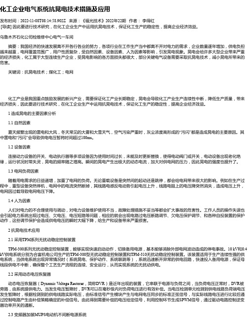
化工企业电气系统抗晃电技术措施及应用发布时间:2022-11-08T08:14:58.902Z 来源:《福光技术》2022年22期作者:李得红[导读] 因此要进行技术研究,在化工企业生产中运用抗晃电技术,保证化工生产的稳定性,提高企业经济效益。
乌鲁木齐石化公司检维修中心电气一车间摘要:我国经济的快速发展离不开各行各业的努力,各项行业在工作生产当中都离不开对电力的需求,企业数量逐年增加,供电负担越来越重,电网覆盖范围广,用户性质复杂,受自然因素、设备因素、人为因素等影响,引发晃电现象。
晃电会给许多大型企业带来严重的经济损失,化工属于大型连续生产企业,受晃电影响的各方面损失都很大,部分关键电气设备需要采取抗晃电技术,减小晃电所带来的危害。
关键词:抗晃电技术;煤化工;电网化工产业是我国重点鼓励发展的新兴产业,需要保证化工产业长期稳定,晃电会导致化工产业生产连续性中断,降低生产质量,带来经济损失,因此要进行技术研究,在化工企业生产中运用抗晃电技术,保证化工生产的稳定性,提高企业经济效益。
1 造成晃电的主要因素分析1.1 自然因素夏天频繁出现的雷电和大风,冬天常见的大雾和大雪天气,空气污染严重时,灰尘浓度高形成的“污闪”都是造成晃电的主要原因。
其中雷电和“污闪”会导致供电电压暂将时间超过100ms。
1.2 设备因素连接动力设备的开关、电动执行器等多项设备因为使用时间过长,未能及时更新替换,使得电动阀门或开关,电动设备出现老化绝缘,运行状况时常失灵,晃电的频率随之增高。
瞬间的晃电产生出极大的动态电流,加大对供电网的压力,因此晃电的强度也提升了。
1.3 电网负荷因素随着用电需求的日益递增,加重了电网的负荷。
无论重载设备是突然间的起动还是跳停,都会给电网带来很大的影响。
例如在生产过程中,重型设备突然停机,电网中的电流突然断掉,其线路电感反电动势引起电压上升,线路电阻上的电压降突然消失,造成电压上升,电网因过载导致电网电压下降。
TPM-310型使用说明书V2.10

4.3.0主菜单
按上下键移动光标,按确认键后进入对应子菜单。下同。
1.测量显示
2.定值设置
3.试验
4.追忆
5.校时
6.密码通信
7.异常报告
4.2
4.2.1“测量显示”一级子菜单,单位:标幺值
U1a= * *. *%
U1b= * *. *%
U1பைடு நூலகம்= * *. *%
UJ1a= * *. *%
UJ2a= * *. *%
母线I段与馈线II段舜时压差。
母线II段与馈线I段舜时压差。
母线I段零序电压U0m1。
母线II段零序电压U0m2。
4.2.2“定值设置”一级子菜单
定值设置时,上下键可以翻屏,当光标在数字键区域时,当连续按加减键时,数字可连续加减。所在行定值在输入完后必须按“确认”键,此时,合理定值将被写入装置的非易失ROM中,为保证可靠性,装置内部自动检查整定定值范围,越限定值将无法整定进装置。按每屏显示的菜单及说明如下:
装置故障此信号发出时,表明装置自检到某些主要部件出了故障,应立即通知制造厂。
3.2
运行状态指示灯“进线一”和“进线二”指示灯正常时应亮;“母联”灯应不亮;“动作”和“闭锁”灯应不亮。
测量显示:显示出的电压、压差等均应与实际状态相一致。
定值设置:各定值应与整定值相一致。
异常报告:应无异常报告。
4.
TPM-310装置使用的液晶为12864点阵,可显示48行的汉字,或816行字符。装置采用汉字显示,操作简便直观。
此时装置面板“装置动作”,“装置闭锁”灯亮,切换完成。
8:进线二保护起动。接进线二变压器或进线二馈线保护出口接点。应将所有需要进行厂用电切换的出口接点并接。接通方式为闭合短脉冲。
- 1、下载文档前请自行甄别文档内容的完整性,平台不提供额外的编辑、内容补充、找答案等附加服务。
- 2、"仅部分预览"的文档,不可在线预览部分如存在完整性等问题,可反馈申请退款(可完整预览的文档不适用该条件!)。
- 3、如文档侵犯您的权益,请联系客服反馈,我们会尽快为您处理(人工客服工作时间:9:00-18:30)。
2. 主要功能
根据断路器的状态自动识别是运行于双进线的方式或是双进线加母联的方式。 装置手动、自动完全分开,人工起动区分菜单起动和手动起动。 根据对象选择实现进线一、母联开关、进线二之间的人工切换或菜单切换,实现六种逻 辑切换。 每种手动切换可选择串联、并联、同时三种切换方式。其中串联、同时切换方式有快速、 同相、残压合闸条件。 事故切换可实现进线一至母联、进线二至母联、进线一至进线二和进线二至进线一的四 种逻辑。 事故切换可选择串联、同时两种切换方式。每种切换方式含有快速、同相、残压合闸条 件。 事故切换起动包含失压起动、品质起动、逆功率起动等模拟量起动方式,以及开关变位 起动、联跳起动、保护起动等开关量起动。 PT 断线报警、过流闭锁、开关接点异常闭锁等。 装置提供保护闭锁、装置闭锁、切换闭锁等多种闭锁功能。 事故记录完善的录波功能以及 USB 导出。 支持 RS485、CAN 等多种通讯方式,支持 IEC61850 通讯以及 IRIG-B 对时功能。
TPM-310-2 无扰动稳定控制装置 技 术 说 明 书
合富共展机电科技有限公司
二 0 一二年六月
目
录
1. 2. 3. 3.1. 3.2. 3.3. 3.4. 3.5. 3.6. 3.7. 3.8. 3.9. 3.10. 3.11. 3.12. 3.13. 3.14. 4. 4.1. 4.2. 4.3. 4.4. 4.5. 4.6. 5. 5.1. 5.2. 5.3. 5.4. 5.5. 5.6.
3.5. 测量精度
电压电流:≤1% 频率:≤0.02Hz 相角:≤0.2 延时:≤2mS
3.6. 接点输入输出容量
跳合闸出口:DC220V 信号:DC220V 5A
2
5A
TPM-310-2无扰动稳定控制装置 技术说明书
开入量输入:DC48V或DC110V
3.7. 时钟精度
3.11.工作环境条件
环境温度:-30~+70℃
3
TPM-310-2无扰动稳定控制装置 技术说明书
相对湿度:5%~95% 大气压力:80~110Kpa
3.12.其他指标满足DL478-92《静态继电保护及安全自动装置通用技术条件》。 3.13.外形尺寸
标准插箱:225(W)×266(H)×250(D)mm
6. 6.1. 6.2. 6.3. 6.4. 6.5. 6.6. 6.7. 6.8. 7. 7.1. 7.2. 7.3. 7.4. 7.5. 8. 8.1. 8.2. 8.3. 8.4.
闭锁及报警功能 ....................................... 9 保护闭锁 ........................................... 9 装置闭锁 .......................................... 10 开关位置异常及去耦合 .............................. 10 装置异常 .......................................... 10 PT断线 ............................................ 10 后备电源失电监测 .................................. 10 装置闭锁 .......................................... 10 装置失电 .......................................... 11 测量显示、事故记录、录波、打印、通信 ................ 11 测量显示 .......................................... 11 事故记录 .......................................... 11 录波及输出 ........................................ 11 通信 .............................................. 12 GPS对时 ........................................... 12 切换(合闸)原理 .................................... 12 快速切换 .......................................... 12 同相切换 .......................................... 13 残压切换 .......................................... 14 快速切换补充说明 .................................. 15
3.10.抗干扰性能
能承受GB/T14598.14-1998(idt IEC255-22-2)标准规定的严酷等级Ⅳ的静电放电试验。 能承受GB/T14598.9-1995(idt IEC255-22-3)标准规定的严酷等级Ⅳ的辐射电磁场干扰试 验。 能承受GB/T14598.13-1998(idt IEC255-22-1)标准规定的严酷等级Ⅳ的1MHz脉冲群干扰 试验。 能承受 GB/T14598.10-1996(idt IEC255-22-4) 标准规定的严-310-2无扰动稳定控制装置 技术说明书
3. 技术参数
3.1. 装置电源
额定电压:DC220V/DC110V/AC220V(若为交流供电,请使用不间断电源。) 纹波系数:不大于5%
3.2. 额定交流输入
交流电流:5A/1A 交流电压:100 V 或380 V 频率:50Hz
用途 ................................................. 1 主要功能 ............................................. 1 技术参数 ............................................. 2 装置电源 ........................................... 2 额定交流输入 ....................................... 2 功率消耗 ........................................... 2 过载能力 ........................................... 2 测量精度 ........................................... 2 接点输入输出容量 ................................... 2 时钟精度 ........................................... 3 快速切换时间 ....................................... 3 绝缘性能 ........................................... 3 抗干扰性能 ........................................ 3 工作环境条件 ...................................... 3 其他指标 .......................................... 4 外形尺寸 .......................................... 4 重量 .............................................. 4 硬件说明 ............................................. 4 电源模件(POWER) ................................ 5 出口模件(KOUT) .................................. 5 开入模件(KIN) .................................... 5 CPUA模件(CPUA) ................................. 5 CPUB模件(CPUB) ................................. 5 交流模件(AL) ..................................... 5 切换功能 ............................................. 5 切换(合闸)条件 ...................................... 5 就绪条件 ........................................... 6 正常切换(人工切换) ............................... 7 事故切换方式 ....................................... 8 事故切换起动条件 ................................... 8 切换逻辑 ........................................... 9
3.3. 功率消耗
交流电流回路:当I=5A时,每相不大于0.3VA 交流电压回路:当U=100V时,每相不大于0.3VA 直流电源回路:当正常工作时,不大于30W,切换时,不大于50W。
3.4. 过载能力
交流电流回路: 2倍额定电流下装置可连续工作 10倍额定电流下装置可连续运行10S 40倍额定电流下装置可连续运行1S 交流电压回路:1.5倍额定电压下装置可连续工作
装置不仅自身带时钟,还可通过通信进行对时,支持IRIG-BTTL电平或RS485对时,与GPS 进行精确对时,误差≤2ms。