SJC030B测试仪说明书A5
测量仪器说明书

目录一、GeoPluse浅地层剖面仪操作规程 (1)1、仪器简介 (1)1)功能简介 (1)2)系统配置 (1)2、GeoPluse浅地层剖面仪系统配置连接 (1)1)换能器安装 (1)2)5430A收发机与5210A接收机连接 (2)3)接通电源 (4)3、5210A与5430A收发机功能键简介 (4)1)5430A收发机功能键简介 (5)2)5210A接收机功能键简介 (5)4、数据采集后处理 (7)二、Knudsen 320Ms双频测深仪操作规程 (14)1、仪器简介 (14)1)工作原理 (14)2)功能简介 (14)2、系统配置连接 (15)1)换能器连接 (15)2)Knudsen 320Ms主机与电脑的连接 (15)3)接通电源 (16)3、Knudsen 320Ms菜单结构 (16)4、数据采集后处理 (21)三、TideMaster型潮位仪操作规程 (29)1、仪器硬件设置 (29)1)主要设备仪器 (29)2)操作及安装使用 (31)2、临时验潮站站址选择原则 (31)3、仪器的软件设置 (31)四、GPS操作规程 (41)1、工作原理 (41)2、基准站操作 (41)1)仪器架设 (41)2)用手簿启动基准站 (44)3、Trimble SPS461 GPS罗经设置及使用说明 (46)1)网络连接方法设置461 (46)2)SPS461 信标机定位定向仪液晶屏设置说明 (51)五、海底管线铺设导航、定位技术 (64)1、GPS定位原理 (64)2、海洋定位技术 (65)1)差分GPS技术 (65)2)信标差分技术 (65)3、GPS 控制网及基准站的设立解算 (66)1)基准站的选定和设立 (66)2)GPS控制网的布设、施测和解算 (67)3)测区的坐标七参数的解算 (68)4)利用转化参数转换坐标 (69)4、海底管道施工导航定位技术 (69)1)海底管线临时定位桩施工 (69)2)铺管船法海底管线铺设导航定位 (71)六、海底管线预、后调查方案 (75)1、概述 (75)1)项目概述 (75)2)海底管线状态简介 (75)2、使用检测仪器进行海底管线铺设后调查内容 (76)1)海底管线外观检查 (76)2)经处理后的完工调查 (77)3、后调查作业设备及选用原则 (77)1)测深设备 (77)2)旁侧声纳 (78)3)浅地层剖面仪 (78)4、调查作业施工 (79)1)作业准备 (79)2)计划线布设 (79)3)作业方法和步骤 (80)4)作业注意事项 (82)5、数据采集、记录以及报告 (83)1)数据采集 (83)2)数据处理 (84)6、组织机构与职责 (85)一、GeoPluse浅地层剖面仪操作规程1、仪器简介1)功能简介使用GeoPluse浅地层剖面,得到几十米深的纵断面工程地质图,探明海底泥层的构成、岩性、断层位置以及有无埋设其他管道等,然后将所取得的几条走向资料进行对比,以确定最优的路由。
双钳多功能接地电阻测试仪使用手册【模板】

HZJD-S双钳多功能接地电阻测试仪使用手册**市合众电气设备制造有限公司尊敬的顾客感谢您使用本公司产品。
在您初次使用该仪器前,请您详细地阅读本使用说明书,将可帮助您熟练地使用本仪器。
我们的宗旨是不断地改进和完善公司的产品,因此您所使用的仪器可能与使用说明书有少许的差别。
如果有改动的话,我们会用附页方式告知,敬请谅解!您有不清楚之处,请与公司售后服务部联络,我们定会满足您的要求。
由于输入输出端子、测试柱等均有可能带电压,您在插拔测试线、电源插座时,会产生电火花,小心电击,避免触电危险,注意人身安全!衷心感谢您选用了本公司的双钳多功能接地电阻测试仪,您因此将获得本公司全面的技术支持和服务保障。
为了更好地使用本产品,请一定:——详细阅读本用户手册。
——遵守本手册所列出的操作注意事项。
任何情况下,使用本钳表应特别注意安全。
注意本钳表所规定的测量范围及使用环境。
注意本钳表面板及背板的标贴文字。
钳口接触平面必须保持清洁,不能用腐蚀剂和粗糙物擦拭。
避免本钳表受冲击,尤其是钳口接合面。
测量导线电流不要超过本钳表的上量限。
拆卸、校准、维修本钳表,必须由有授权资格的人员操作。
由于本钳表原因,继续使用会带来危险时,应立即停止使用,并马上封存,由有授权资格的机构处理。
关于本用户手册■当您在使用本产品前,请仔细阅读本用户手册并妥善保存以备今后参考之用。
■如果您在使用本产品的过程中有疑问或困难,请及时与本公司联系。
目录一、引言 (4)二、概述 (4)三、主要特点 (4)四、主要技术指标 (5)五、面板功能简介 (5)六、测量原理及使用方法 (6)七、注意事项 (11)八、装箱清单 (11)一、引言欢迎使用高质量专业测试仪表HZJD-S双钳多功能接地电阻测试仪,该仪器用于接地电阻的测量,并在此基础上评价接地质量。
该仪器是基于我们多年接地电阻和电气安装测试设备的生产和开发经验设计并制造。
HZJD-S双钳多功能接地电阻测试仪是一种手持式的接地测量仪。
索佳B20 B30 B40自动安排水准仪使用说明书
索佳计量器具型式批准证书编号:2016L120-44执行产品标准:GB/T10156-2009 水准仪B20/B30/B40自动安平水准仪 使用说明书这是日本测量仪器制造厂商协会的标志。
测量仪器索佳B20/B30/B40自动安平水准仪使用说明书感谢您购买索佳B20/B30/B40自动安排水准仪。
●使用本产品之前,请仔细阅读本说明书。
●检查仪器包含的所有设备。
“8. 标准配置”●本说明书的内容可能会未经告示而改变。
●本说明书的插图为B20的图形。
●为便于阅读,说明书中部分插图进行了简化处理。
●仪器的技术指标和外观随时可能改变而有别于本说明书。
恕不另行通知,敬请谅解。
目录1.安全操作注意事项 (1)2.注意事项 (5)3. B20/B30/B40特点 (7)4.仪器部件名称 (8)5.测量准备 (9)5.1仪器设置 (9)5.2调焦和照准 (11)6.测量方法 (13)6.1高差测量 (13)6.2水平角测量 (15)6.3视距法距离测量 (16)7.检验和校正 (17)7.1圆水准器检验和校正 (17)7.2自动补偿器检验和校正 (19)7.3十字丝(视准轴)检验和校正 (20)8.标准配置 (22)9.可选配件 (24)10.技术指标 (27)1.安全操作注意事项为了确保仪器安全操作,避免造成人员身体伤害或财产损失,本说明书使用“警告”或“注意”来提示应遵循的条款。
在阅读本说明书主要内容之前,请首先弄清这些提示的含义。
提示含义警告忽视本提示而出现错误操作,可能会造成操作人员的重伤或死亡。
注意忽视本提示而出现错误操作,可能会造成操作人员的受伤或财产损失。
本符号用于需特别注意条款的提示,有关细节说明随符号给出。
本符号用于禁止条款的提示,有关细节说明随符号给出。
本符号用于必须执行条款的提示,有关细节说明随符号给出。
1一般情况警告禁止直接用望远镜观察太阳,以免造成眼睛失明。
禁止用望远镜观察经棱镜或其它反射目标反射的太阳光,以免损伤视力。
cm-03型便携式cod测定仪操作手册共12页文档
简便操作方法本公司仪器出厂前已经经过校准,无需再做标准曲线,用户可以直接采用下面方法快速测量水样的COD值。
1、打开加热器和测定仪开关,按加热器的“确定”键,仪器开始升温。
测定仪显示H,输入两位操作员编号按确定键,显示时间。
2、取3支洗净并且烘干的专用比色管,其中2支分别加入待测水样,另外1支加入1.5ml蒸馏水或纯净水作为空白,然后分别在3个专用比色管中加入0.5ml 1号试剂、1.5ml 2号试剂、2.5ml3号试剂。
3、加热器显示“OK”后将上述3支专用比色管放入加热器中并且按“确定”键,仪器开始计时,15分钟后仪器发出报警声,表示消解时间到,取出比色管,冷却到不烫手。
4、将3支专用比色管擦拭干净等待测量。
5、首先取加入蒸馏水的专用比色管插入测定仪的比色孔,按测定仪的“功能”键加4(按“功能”再按“4”),进入水样测量状态,显示“P”,按采用的曲线号:1为高量程(200-2500mg/L),2为低量程(0-200mg/L),按确定后显示“A0”,放入空白水样后按“确定”键开始调零,读数稳定后按“确定”键,仪器显示“n1”。
6、取2支装有水样的专用比色管中的1支放入比色孔中按“确定”键,仪器显示吸光度数值,稳定后按“确定”键,显示数值即为第一个水样的COD实际数值,然后再按“确定”键,显示“n2”;放入第二个水样其他操作同第一个水样,仪器显示“n3”后按“.”结束测量。
注意事项(1)每次测试时将试管的白色标签面对测试者。
(2)每次分析前应将专用比色管烘干,可将专用比色管放在加热器的加热孔中烘干。
(3)为了减少操作的系统误差,每次分析要做空白试验。
(4)如全部试剂加入后溶液颜色不匀,应将其冷却后摇匀,再进行消解。
(5)如水样中的氯离子含量较高(≥2000mg/L),不配置1号试剂,而是在消解前根据水样中的氯离子浓度直接将适量的硫酸汞粉末加入专用比色管(汞:氯≥10)即可达到消除氯离子干扰的目的。
测试仪器说明书

生产验证测试流程图 第二章 安装 检查包装当您收拆开全新的ND-5000/5001后,请如下检查随机物品是否有短缺,如有短缺请尽速与本公司服务人员或本产品代理商联系。
检查无误者可在左边方格打勾。
□ ND-5000+/5001X 1□ 产品光盘(内含电子手册) X 1□ 中文操作手册 X 1□ AC 电源线 X 1□ 3转2 AC 电源转接头 X 1□ RS-232缆线(9母←→9母) X 1□堆栈用连接线(ND-5000+ Slave Only) X 1□ 产品保证卡X 1□ 产品测试报告X 1 硬件安装扩充卡安装说明1 ND-5000在出厂时皆已为客户安装好指定Port数的扩充卡。
故实际上在您收到机器时,只需将其接上电源即可操作使用。
为使您明了扩充卡安装过程,以便日后自行扩充或更换。
在此以16埠机种安装做为示范。
ND-5000提供了四个扩充槽,如图中Slot 1到Slot 4。
本例中我们需要装上2片EC-5000P的扩充卡,请卸下机背上Slot 1和Slot 2的饰板螺丝钉(图中圈起来处)。
2 卸下饰板螺丝钉后,即可将Slot 1和Slot 2的饰板取下。
3 将第一片EC-5000P扩充卡水平插入Slot 1中。
插入时请对准两侧固定沟,再徐徐推入至底部总线中。
当扩充卡顶到总线插座时,请稍用力推入,以确保扩充卡上的排针能确实进入插座中。
然后将原先的饰板螺丝钉锁上扩充卡尾端的固定孔即可。
第二片扩充卡的安装同上。
如需安装第三、第四片卡,则请重复步骤一至三。
4 锁定饰板螺丝钉后,即安装完成。
日后如需拆换卡时,也是先卸下饰板螺丝钉,然后以双手同时抓住卡耳,依杠杆原理向两侧顶,再向后拉即可拆下扩充卡。
堆栈安装说明使用两台堆栈时,将堆栈线任一端接至Master机台上的"NDT Stack OUT",再将另一端接至Slave机台上的"NDT Stack IN"。
如需再连接第二台Slave机台,则将另一条堆栈线任一端接至第一台Slave机台上的"NDT Stack OUT",另一端接至第二台Slave机台上的"NDT Stack IN"。
3B SCIENTIFIC 数字多功能测量仪说明书

3B SCIENTIFIC ® PHYSICSDigital Multimeter E 1006809Instruction sheet11/14 SD/UD1 Measuring probe 1a Finger guards2 Measurement socket “20 A” for current measurement in 20-A range (positive)3 Measurement socket “A” for current measurement for up to 2 A (positive)4 Measurement socket “COM“ (negative)5 Measurement socket “V/Ω“ for voltage and resistance meas-urement (positive)6 Transistor test socket7 Measurement range dial8 Hold function button9 On/Off switch 10 Display11 Unlock button1. Safety instructions/using the equipment safelyDigital multimeter E is designed to display elec-trical measurements in the ranges and meas-urement environments specified in its technical data.It conforms to safety regulations for electrical measurement, control and laboratory equip-ment, as specified in DIN EN 61010-1, protec-tion class 2 and to excess voltage category CAT I for up to 1000 V. It is intended for measurements on experiments and laboratory apparatus. It is not approved for measurements on low-voltage mains distribution equipment, such as sockets, fuses, etc.CAT I: Signal layer, telecommunications, elec-tronic equipment with only minor excess voltage transientsCAT II: domestic appliances, mains sockets, portable instruments etc.CAT III: Supply via buried cabling, built-in swit-ches, automatic circuit breakers, sockets or contactorsCAT IV: Equipment and installations supplied, for example, by overhead mains cables and therefore subject to greater risk of lightning strikes. This includes, for example, main swit-ches at the building mains feed, electricity me-ters and ripple control receivers.Safe operation of the multimeter is guaranteed if it is solely used as specified. Safety cannot be guaranteed, however, if the multimeter is used incorrectly or handled without due care and at-tention. In order to avoid serious injury due to current or voltage shocks, the following safety instructions are to be observed at all times:• Carefully read the instruction manual beforeusing the multimeter and obey the instruc-tions therein.• The multimeter may only be used by per-sons who are able to recognise the risks of contact and take due precautions to avoid them.This multimeter is not a toy and must not fall into the hands of children.• Do not place it, keep it or use it anywherewithin reach of children.• When the multimeter is used by teenagers,trainees etc., a suitable person should su-pervise to ensure the equipment is used safely.• If measurements are made where there areany risks of coming into contact with electric-ity, a second person is to be informed.The assumption needs to be made that unfore-seen voltages may be present in the vicinity of objects being measured (e.g. faulty equipment or capacitors).•Before using the multimeter, check the housing and measuring leads for damage and if there should be any malfunctions or visible damage, the multimeter is not to be used. Pay specific attention to the insulation for the measuring sockets.•Be particularly careful when measuring volt-ages in excess of 33 V AC (RMS) or 70 V DC.•The authorised measuring range is not to be exceeded. If measurements are made when the magnitude of the variable is unknown, always select a large measuring range be-fore shifting down to lower ones.•The multimeter may not be used to make measurement on circuits which exhibit co-rona discharge (high voltage). •Particular care is to be taken when making measurements on high-frequency circuits where dangerous voltages may arise due to superimposition of components.•Make very sure that the voltage value be-tween the measured contact and earth or between the ground socket and the meas-urement socket does not exceed 1000 V. •In order to check that the multimeter is ready to use, select the battery test function. Af-terwards, it is then possible to check that the voltage source is disconnected and no volt-age is present.•The multimeter may only be used in a dry, dust-free environment with no risk of explo-sions occurring.•When measuring current in a circuit, make sure to switch off the power before connect-ing the multimeter into the circuit.•When making measurements, always con-nect the ground lead first. Disconnect the sig-nal measurement lead before unplugging the ground.•When using the measuring leads always hold them with your fingers behind the finger guard.•To avoid false readings, which may result in electric shocks or injuries, always replace the battery as soon as the flat battery indica-tor ( + - ) is displayed.•Turn off the multimeter before opening the casing, disconnect the power to the circuit and the measuring leads from the multime-ter.•Never use the multimeter when its casing is open.2. Equipment supplied1 Digital multimeter1 Pair of measuring probes1 Battery1 Instruction manual3. Symbol legendHazard, read instruction sheetDangerous voltagesV DC voltageADC currentVAC currentEarth symbol┴Ground symbol4. Technical dataGeneral specificationsDimensions: 90x190x35 mm approx. Weight: 310 g approx. (with bat-tery)Display: 3½-digit LCD,24 mm, max. 1999 Operating voltage: 9-V battery, 6F22 Automatic cut-off: After 15 minutes Fuse: F2A/250 V Connectors: 4-mm safety sockets Measurements/second: 2 – 3 timesOverload display: “1” shown on display Overload protection:Voltage limits: 1000 V long-term in allvoltage ranges Current limits:2 A range: max. 2 A20 A range: max. 20 A for 10 s withminimum interval 15minsOperating temperature: 0°C – 40°C with0 – 75% humidity Storage temperature: -10°C – 50°C with0 – 75% humidity Electrical safety:Safety specifications: EN 61010-1 Excess voltagecategory: CAT I: 1000 V Contamination level: 2Protection type: IP20 Electromagnetic compatibility: Interference emission: EN 55011:2009 Interference resistance: EN 61326-1:2013Electrical specificationsVMeasuring rangeAccuracy200 mV ±0.5 % ± 3 digits2 V, 20 V, 200 V ±0.8 % ± 2 digits1000 V ±1.0 % ± 2 digitsDC voltageInput impedance: 10 MΩVMeasuring range Accuracy20 µA ±1.8 % ± 2 digits200 µA, 2 mA, 2 mA20 mA, 200 mA±2.0 % ± 2 digits2 A, 20 A ±2.0 % ± 10 digitsDC currentMeasuring voltage drop: 200 mVA6.1 Method of measurementWarning! Dangerous voltages maybe present at the input terminals andmay not be displayed.6.1.1 Voltage measurement•Set the measurement range dial at the re-quired position or . •Connect the black test lead to the meas-urement socket "COM" and the red test lead to the "V/Ω" socket. The meter is connected parallel to the measuring point. The polarity of the red lead connection will be indicated at the same time as the voltage.Note•lf the voltage to be tested is unknown be-forehand, set the measurement range dial to the highest range and work down.•When only the figure "1" is displayed, over range is being indicated and the measure-ment range dial has be set to a higher range.•Never measure voltages higher than 1000 V.6.1.2 Current measurement•Set the measurement range dial at the re-quired position or . •Connect the black test lead to the meas-urement socket "COM" and the red test lead to the "A" socket for measurements up to2 A. For measurements over 2 A connect itto the socket “20A”. The meter is connected in series to the measuring object. The polar-ity of the red lead connection will be indi-cated at the same time as the current.Note•lf the current to be tested is unknown be-forehand, set the measurement range dial to the highest range and work down.•When only the figure "1" is displayed, over range is being indicated and the measure-ment range dial has be set to a higher range.•Limit measurements in the 20-A range to max. 15 s.6.1.3 Resistance measurementWarning! To avoid electrical shockor damage to the meter when meas-uring resistance in a circuit, makesure the power to the circuit isturned off and all capacitors aredischarged.•Set the measurement range dial to the Ω range.•Connect the black test lead to the meas-urement socket "COM" and the red test lead to the "V/Ω" socket. Measurement is done parallel to the resistor Note•lf the resistance to be tested is unknown beforehand, set the measurement range dial to the highest range and work down. •When only the figure "1" is displayed, over range is being indicated and the measure-ment range dial has be set to a higher range.When the input is not connected, i.e. at open circuit, the figure "1" will be displayed for the over range condition.6.1.4 Diode test•Set the measurement range dial to. •Connect the black test lead to the meas-urement socket "COM" and the red test lead to the "V/Ω" socket.A built-In buzzer sounds if the resistance is less than 30 ± 10 Ω.6.1.6 Transistor hFE test•Set the measurement range dial to hFE. •Make sure the transistor is "NPN" or "PNP"type. Insert the transistor correctly into the corresponding transistor test socket. Display reading is approx. transistor hFE value. Base current approx. 10 µA, V CE approx.2.8 V.6.2 LCD Display panel angle selectionLCD display panel is locked in lie down position in normal operating condition and storage. •To change the display panel angle, push down the button which is above the top case, and release lock.•Rotate the display panel to the best angle.7. MaintenanceTurn off the meter and remove the testleads before you service or clean thedevice.Beyond replacing batteries and fuses, do not attempt to repair or service your meter unless you are qualified to do so and have the relevant calibration, performance test, and service in-structions.7.1 Battery and fuse replacementReplace the battery as soon as the flatbattery icon ( + - ) appears.Remove from the multimeter any bat-teries which are flat or starting to disin-tegrate.Also remove batteries from the mul-timeter if it has not been used for a longperiod of time.Turn off the meter and remove the testleads before opening the case. •Loosen screws with suitable screwdriver and remove case bottom.•Replace the battery or the fuse. •Replace the case bottom and reinstall the three screws. Never operate the meter unless the case bottom is fully closed.•Do not dispose of the battery in regularhousehold refuse. Fol-low the local regula-tions (In Germany: BattG; EU: 2006/66/EG). 7.2 Cleaning•Periodically wipe the case with a damp cloth and mild detergent.•Do not use abrasives or solvents.Dirt or moisture in the measurement sockets can affect readings.•Shake out any dirt that may be in the meas-urement sockets.•Soak a new swab with isopropyl alcohol and work around the inside of each measure-ment socket.8. Disposal•The packaging should be disposed of at local recycling points.•Should you need todispose of the equip-ment itself, neverthrow it away in nor-mal domesticwaste.Local regulations forthe disposal of electri-cal equipment will ap-ply.•Do not dispose of the battery in regular household refuse. Follow the local regula-tions (In Germany: BattG; EU: 2006/66/EG).3B Scientific GmbH ▪ Rudorffweg 8 ▪ 21031 Hamburg ▪ Germany ▪ 。
精工自动化检测系统 使用指南说明书

Optical AutomatedInspection for Intelligent Production LinesTechnical Parameter3D SystemTypeUltra-fast scanningLaser lines in totalAccuracy Measurement rate up toScanning area 0.025 mm1,900,000 measurements/s310 mm × 350 mm 1 extra blue laser line42Deep hole scanning17 blue laser crosses AutoScan-T427 blue parallel laser linesHyperfine scanning0.020 mm Volumetric accuracy (With MSCAN-L15 photogrammetry system)Stand-off distance Depth of fieldOutput formats Operating temperature rangeInterface modeUSB 3.0Patents Laser class Resolution10.4 m³18.0 m³0.064 mm 0.044 mm + 0.012 mm/mCLASSⅡ (eye-safe)0.078 mm 300 mm 320 mm.stl, .ply, .obj, .igs, wrl, .xyz, .dae, .fbx, .ma, .asc or customized-10°C ~ 40°CCN204329903U, CN104501740B, CN104165600B, CN204988183U, CN204854633U, CN204944431U, CN204902788U, CN105068384B, CN105049664B, CN204902784U, CN204963812U, CN204902785U, CN204902790U, CN106403845B, CN209197685U, CN209263911U, CN106500627B, CN106500628B, CN206132003U, CN211121096U, US10309770B2, KR102096806B1Volumetric accuracyScan modeSCANTECH (HANGZHOU) CO., L TD(1) ISO 17025 accredited: Based on VDI/VDE 2634 Part 3 standard and JJF 1951 specification, probing error (size) (PS) performance is evaluated.(2) ISO 17025 accredited: Based on VDI/VDE 2634 Part3 standard and JJF 1951 specification, sphere spacing error (SD) performance is evaluated.(1)(2)SCANTECH (HANGZHOU) CO., L TDBuilding 12, No.998, West Wenyi Road, Yuhang District, Hangzhou, Zhejiang Province, ChinaTel: 0086-571-85852597 Fax: 0086-571-85370381E-mail:********************Website : Copyright ©Based on automatic optical tracking and seamlessly integrated into production line, it is designed for online batch inspection and enhances iterativeefficiency of the production process greatly.Work Seamlessly with Production LineConjunction with handheld 3D scanner, portable CMM, MSCAN photogrammetry system, rotary platforms, and guide rails, realize simultaneous optical tracking and scanning and personalizedsolutions.Multiple ConfigurationsWith adoptions of blue laser and synchronoustracking technologies, it reaches up to 1,900,000 measurements/s and accuracy of 0.025 mm. Efficient and flexible automated manufacturing can beachieved without being affected by external factors.Speed up Precise InspectionBeing insusceptible to temperature, vibration, dust, etc., the military-grade design presents superior adaptability in harsh industrial environment.Military-grade QualityDue to one-click start, offline programming and automatically generating inspection, it enables simple operation for users, regardless of their experience, to easily finish the measurement.Simple OperationAutoScan-T42 automated 3D system is a new upgrade for intelligent automatic inspection. It is specially designed for automated quality control in shop-floor conditions, facilitating enterprises to achieve the optimum matching between cost and efficiency.AutoScan-T42 conducts non-destructive scanning without attaching markers. Its seamless connection with production line greatly contributes to the reduction the workload. The military-grade manufacturing qualitypresents strong anti-interference and high adaptation to complex and harsh workshop environment. It can be extensively used in national defense, energy, 5G, mold manufacturing, etc., users can easily operate the system owing to one-click start, offline programming, and compatibility with 3D software.。
测试仪使用说明书

转辙机综合测试仪使用说明书一、开机/关机1.开机按下键并保持2-3s后,仪器开机并开始初始化自检,自检期间蜂鸣器鸣响。
初始化完毕后进入主菜单,蜂鸣器停止鸣响,进入主菜单开机完毕。
主菜单显示当前存储器通道号、当前道岔号、当前日期、时钟及电池电量。
2.关机在任意状态下,按下键后仪器即时关机,关机后关闭所有电源。
并将部分设定内容存储。
二、设定内容及操作方法1.显示液晶对比度当显示液晶受温度、光照等因数造成显示不清时,你可以通过设置液晶的显示对比度进行修正。
在主菜单下按键及键可调整液晶的显示对比度。
设定内容可自动保存。
2.显示液晶辅助背光开关当使用环境的光线不足、能见度较低,你可以开关液晶的辅助背光。
在主菜单下按键及键可开关液晶的辅助背光。
设定不可保存。
3.修改当前通道在自动、手动、显示等菜单中按键及键可改变当前的默认存储通道。
4.设置菜单在主菜单下按键后进入设置菜单,你可以在此菜单中修改道岔号、当前时钟、打印数据间隔。
1)改变当前的道岔号在设置菜单中选择1进入。
显示当前的道岔号,随光标位置输入新的道岔号后按确定完成修改。
2)调整日期、时钟在设置菜单中选择2开始进行调整。
随光标位置输入新的日期、时间后按确定完成修改。
3)修改打印数据间隔在设置菜单中选择3进行修改。
首先显示的是当前的打印数键或键来进行修改,设定范围为0.15s – 0.9s,设定间隔为 0.15s。
三、电池充电当电池电量降至30 %时,仪器的蜂鸣器鸣响,电池欠电报警,请立即停止使用,并请及时充电。
当可能较长时间不用时,请带电保存。
并请每3个月充电一次。
电池的充电时间为12-16 小时。
四、连接、联线请将综合测试线的电压测试线并接在转辙机电机电源线的任意两相上。
请将综合测试线的电流测试线串接在转辙机电源线的回路中。
请将综合测试线的时间测试线接在转辙机到位闭合的一组备用接点上。
请将拉力传感器替换转辙机与安装装置的连接销后用联线与仪器连接。
请将压力传感器替换转辙机被测压力腔侧的二动调节阀后用联线与仪器连接(只限于电液转辙机)。
系列钳形接地电阻测试仪说明书

ETCR2000系列钳形接地电阻测试仪使用手册武汉智能星电气有限公司2012-2-20目录一、概述2二、功能特点2三、产品规格41、型号说明:42、量限及准确度43、基本参数4四、外形结构5五、显示部分6六、使用方法7七、故障排除10八、注意事项11九、运输、贮存11十、售后服务12十一、附录12ETCRCR2000系列钳形接地电阻测试仪一、概述ETCR2000系列主要用于电力、电信、气象以及其它电气设备的接地电阻测量。
使用这种方法测量时,不用辅助电极,不存在布极误差。
重复测试时,结果的一致性非常好。
国家有关部门对钳形接地电阻测试仪与传统电压电流法对比试验的结果说明,它完全可取代传统的接地电阻测试方法,准确地测量出接地电阻。
在实际应用中,2000系列钳形接地电阻仪在各行各业,各种不同的使用环境中得到了广大客户的认同。
二、功能特点对比传统电压电流测试法,2000系列钳形接地电阻仪优越性能表现如下:1. 操作简便:只须将钳表的钳口钳绕被测接地线,即可从液晶屏上读出接地电阻值。
而传统电压电流测试法必须将接地线从接地系统中分离,同时还要将电压极及电流极按规定的距离打入土壤中作为辅助电极才能进行测量。
2. 测量准确:传统电压电流测试法的准确度取决于辅助电极之间的位置,以及它们与接地体之间的相对位置。
另外,电压极电流极与接地体之间的土壤电阻率的不均匀性都会影响测量结果。
如果辅助电极的位置受到限制,不能符合计算值,则会带来所谓布极误差。
对于同一个接地体,不同的辅助电极位置,可能会使测量结果有一定程度的分散性。
从而影响测量的准确度。
不存在布极误差。
只要客户在测量时,先对本产品附带的测试环进行测量,如果读数准确,那么之后所测量的接地电阻值就是准确的。
3. 不受周围环境限制:传统电压电流测试法因为要设置两个有相对位置要求的辅助电极,所以对周围环境是有要求的,否则会影响测量的准确度。
而随着我国城市化的发展,有时被测接地体周围很难找到土壤,它们全被水泥所覆盖,何况还要找到满足相对位置要求的土壤,有时就更为困难。
水测试仪用户手册说明书

50 1.47%
CANCEL - hold 5 sec
A graph will be plotted during the test time (180 seconds for the EasySHIP Test and 120 seconds for the Reagent B Test).
Test complete
Always start the test with the highest range selected, when in doubt about the approximate amount of water in your test oil. Overpressure can occur if an oil sample is tested with a very high water content on the low range 100-3000ppm. This can cause permanent damage to the pressure sensor.
5)Replace Lid
BACK
START
NB: The amount of oil and reagent used changes with the range. Always use gloves when handling EasySHIP Sachets.
*Squeeze all of the EasySHIP Paste into the centre of the cell ** Range 100 - 3000ppm = Add 35ml ReagA
Range 0.02 - 1.0%
WATER TEST
Range 0 - 10% Range 100 - 3000ppm
各种检验测试仪器使用说明
检验测试仪器使用说明:目录:1,指针式推拉力计使用说明----------------------2 2,手持式扭力计使用说明-------------------------5 3,尖点测试仪使用说明----------------------------6 4,各种千分尺使用说明----------------------------8 5,游标卡尺使用说明------------------------------13 6,塑胶硬度计使用说明---------------------------15 7,一,指针式推拉力计使用说明一、推拉力计简介Nk系列推拉力计是小型便攜式的拉力、压力测试仪器,具有高精度、易操作、可同时显示牛顿和公斤单位、攜带方便之优点,而且有一个可作荷重峰值(PEAK)测试及连续荷重值(TRACK)测试切換使用的切換旋钮(PEAK/TRACK钮)。
现广泛应用于电子、高低压电器、五金製锁、汽车配件、粘胶化工、打火机及点火装置、製笔、轻工、建筑、纺织、机械等行业和科研机构作拉压负荷、插拔力、破坏性试验测试等,是老式测力计的替代产品。
使用本仪器前请详细阅读此说明书,以便充分运用本仪器所具有的功能,使测试时能得到准确的数值。
二、随机附件明细表略三、结构名称四、外形及安装尺寸五、测试前准备选择合适的测试用接头夹具,安装到推拉力计上。
(1) 拉伸测试将拉伸用夹具安装到推拉桿上标示拉(PULL)的一端。
(2) 压缩测试将推压用夹具安装到推拉桿上标示压(PUSH)的一端。
(3) 加长桿的应用当单凭拉、压用夹具无法接触到被测试物时,请利用加长桿来安装夹具。
注意:测试时,被测试力与推拉力计的推拉桿需在同一直线上,否则无法测得准确的荷重值。
(4) 切換旋钮的使用方法(a) 荷重峰值(PEAK)——连续荷重值(TRACK)的切換:将切換旋钮轻轻的往下压同时往左方向转,使旋钮的“●”标记停在连续荷重值(TRACK)的位置上。
SL-030B型重锤式表妹电阻测试仪 说明书

SL-030B型重锤式表面电阻测试仪使用说明书概述本仪器是高集成度微电脑的3.1/2位LCD(LED)双数字显示,便携式绝缘表面电阻测试仪(高阻计)。
量程从10×103Ω~10×1012Ω,同时配有高精度数字温湿度传感器。
机内测试电压为DC10V和100V自动切换。
以数字直接显示出电阻值,精度高、显示迅速、稳定性好、读数方便。
本仪器适用于防静电产品如防静电鞋、防静电塑料橡胶制品、计算机房防静电活动地板等的检验和电子电器产品的绝缘电阻测量。
SL-030B型数字绝缘电阻测试仪(高阻计)适用于测量绝缘材料、电工产品、各类元器件的绝缘电阻,还能测量在不同温度下的塑料电线电缆(无屏蔽层)的绝缘电阻。
规格和技术参数1. 电阻测量范围: 10×103Ω~10×1012Ω2. 温度测量范围:-0~50.℃3. 湿度测量范围:0~100%RH4. 显示: 3 .1/2位LCD(LED)双显示5. 分辨率:1/20006. 准确度: 0.5%~5%7. 机内测试电压: 10V ,100V自动切换8. 供电形式: 9V电池9. 仪器尺寸: 175mm× 98mm× 50 mm10. 质量: 约300g11. 重锤:2.5kg×2仪器结构及工作原理1 结构由直流高压测试电源、高阻抗直流放大器、重锤和显示器组成。
2 工作原理根据欧姆定律,被测电阻Rx等于施加电压V除以通过的电流I, 即R=V/I 普通的高阻计(主要是指针式高阻计和一些常用的数字高阻计)的工作原理是测量电压V固定,通过测量流过取样电阻的电流I来得到电阻值。
从上式可以看出,由于电流I是与电阻成反比,而不是成正比,所以电阻的显示值是非线性的,即电阻无穷大时,电流为零,即表头的零位处是∞,此处的刻度非常密,分辨率很低。
整个刻度是非线性的。
又由于测量不同的电阻时,其电压V也会有些变化,所以普通的高阻计的精度是很难提高的。
科研检测仪使用说明说明书

目录一、产品技术参数 0二、性能特点 0三、术语定义 (1)四、面板布置 (2)五、菜单操作说明 (3)5.1主菜单【设置】: (4)5.2主菜单【测试】 (6)5.3主菜单【查看】 (7)5.4主菜单【文件】 (9)5.5主菜单【帮助】 (9)六、现场连线 (9)6.1地线与断口线 (9)6.2分合闸控制线 (9)七、传感器的安装 (10)7.1旋转传感器 (10)7.2、直线传感器 (11)附录一、使用仪器所测得的部分图形和文本结果 (11)附录二、内部电源控制接线图 (12)附录三、断口接线图(三断口) (14)附录四、测试现场常见技术问题及处理办法 (14)附录五、技术答疑 (17)I一、产品技术参数1.1、使用环境输入电源220V±10%50Hz±10%大气压力86~106kpa 温度-10~40℃湿度≦80%RH 1.2、安全性能绝缘电阻>2MΩ介电强度电源对机壳工频1.5KV耐压1分钟,无闪络与飞弧。
1.3、基本参数◆时间:量程4000.0ms分辩率0.1ms误差①100ms以内0.1ms±1个字◆◆◆◆输出电源:DC30~250V数字可调/20A(瞬时工作)◆外形尺寸:360mm(L)×280mm(W)×300mm(H)◆重量:9kg二、性能特点2.1产品性能●时间:12个断口的固有分、合闸时间,同相同期、相间同期。
●重合闸:每断口的合-分,分-合,分-合-分过程时间:一分时间、一合时间、二合时间、金短时间、无电流时间值。
●弹跳:每断口的合闸弹跳时间,弹跳次数,弹跳过程,弹跳波形;每断口的分闸反弹幅值。
●速度:刚分、刚合速度,最大速度,时间-行程特性曲线。
●行程:总行程,开距,超行程,过冲行程,反弹幅值。
●电流:分、合闸线圈的分、合闸电流值、电流波形图。
●动作电压:机内提供DC30~250V/20A数字可调断路器动作电源,自动完成断路器的低电压动作试验,测量断路器的动作电压值。
三丰surftest sj-301便携式粗糙度测试仪使用手册说明书
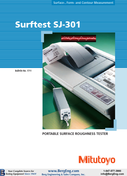
•The large LCD window makes it easy to readmeasurement resultand analysis graph at a glance. The profile-speed thermal printer prints out clear and fast.•Designed to increaseoperability – the large keypads are used for measuringoperations, while the touch panelLCD is used for setting various measurement conditions.•Measured data can be downloaded to a PC. Various analyses can be made by using Surfpak-SJ, dedicated software for surface texture analysis.A portable surface roughness testerwith a touch-panel LCD and a built-in printer.Surftest SJ-301Conforming to various standards•Conforming to the JIS (1994/1982),ISO, DIN, and ANSI standards.•Additionally, the horizontal roughness parameters S, Sm, tp (mr) can be reported. The SJ-301 also performs such special parameters as plateau rate and RK-related parameters.Storing measurement conditions and data•The SJ-301 main unit can store a maximum of 5 sets of measuring conditions. Individual measuring conditions can be selected for each workpiece.•The measuring conditions stored in the SJ-301 can be recalled and switched by direct key operations.•Measured data can be saved at the measurement site and be printed out or recalculated later.•By using an optional memory card, a maximum of 20 sets of measuring conditions, measured data, and statistical results can be stored.High-speed thermal printer•Equipped with a highly sophisticated,high-speed thermal printer.•Selectable orientation for printout –Choose the portrait for conventional printout or the landscape for printing out the image as it is displayed.•BAC (Bearing Area Curve) and ADC (Amplitude Distribution Curve) can be printed out.Key-masking function•This function limits touch panel operation to prevent the detector calibration data and measuring conditions from being altered or deleted.•Measuring conditions can be easily controlled among multiple users.Landscape printoutPortrait printoutResistance to environment•The SJ-301 keypads have excellentdurability -- No need to worry about oil stains from the user's hand.Reading profiles in the LCD window•Measurement results and analysis profiles can be read in the LCD window.•Signal waves can be scrolled smaller or larger, enabling the operator to read fine details.Customization function•The user can select only theparameters needed from a variety of surface roughness parameters provided.Mobility•A built-in buttery in the SJ-301 makes it possible to inspect surface roughness even at a site where there is no electrical outlet available.•Portable and convenient – the drive unit and the detector can be stored in the display unit. (Carrying case is a standard accessory.)•Measurement can be performed while the display unit is in the carrying case.The carrying case can be used to protect the display unit.Auto calibration•Calibration can be easily performed by simply inputting and measuring the Ra value inscribed on the roughness reference specimen.•No adjustment with a tool, such as a volume adjustment, etc. is required.Statistical analysis functions•Statistical analysis of one parameter is possible.•Displays and prints frequency histograms as well as statisticalcalculation results (average, standard deviation, maximum value, minimum value, pass ratio).GO/NG judgement function•Tolerance values in three-steps can be set for the surface roughness parameters.•Judgment symbol is displayed in the result display for a quick judgment of GO/NG.Selectable language for display/printoutDisplay/printout language is selectable from among English, German, French,Italy, Spanish and Japanese.Surftest SJ-301 Arbitrary evaluationlength•An arbitrary evaluation length withinthe range of 0.3 mm - 12.5 mm (Unit:0.1 mm) can be set.•Measurement in a limited space, wheremeasurement is difficult under themeasuring conditions in accordancewith JIS standards, is made possible byusing the start-up OFF function.One-step detectorreplacement•Special detectors are available formeasurements that cannot beperformed with a standard detector -such as measurement of small-diameters and deep-grooves.•No tool is required for replacing thedetector. Simply pull out and insert adetector.•Just one SJ-301 can performmeasurement on a variety ofworkpieces, since various types ofdetectors, depending on theworkpiece, can be used.25.2mm (.99")Approx. 21mm (.83")horizontallyApprox. 2mm (.08")verticallyHigh-accuracy detector•SJ-301 employs a differentialinductance method, which is used inhigh-end models.•Measurement with a high-accuracyand a wide measuring range of350µm.•Parameters that require high-accuracyfeed such as Sm and S can bemeasured with the SJ-301.•The detector can be retracted into thedrive unit when the SJ-301 is notperforming a measurement.room to build a highly expandable desktop evaluation system.Surftest SJ-301Specifications**Evaluation length can be specified arbitrary in the range from 0.3mm (.01”) to 12.5mm (.49”).Roughness specimenSurftest SJ-301MichiganPhone: (734) 459-2810IllinoisPhone: (630) 978-5385CaliforniaPhone: (626) 961-9661MassachusettsPhone: (978) 692-8765IndianaPhone: (317) 577-6070North CarolinaPhone: (704) 875-8332Coordinate Measuring Machines Small Tool Instruments and Data ManagementHardness Measuring Sensor Systems Optical Measuring Digital Scale and DRO Systems Surface-, Form- and Contour MeasurementVision Measuring Systems Note: All information regarding our products, and in particular the illustrations, drawings, dimensional and performance data contained in this pamphlet, as well as other technical data are to be regarded as approximate average values. We therefore reserve the right to make changes to the corresponding designs, dimensions and weights. The stated standards, similar technical regulations, descriptions and illustrations of the products were valid at the time of printing. In addition, the latest applicable version of our General Trading Conditions will apply. Only quotations submitted by ourselves may be regarded as definitive.Job No.11B-7。
双钳多功能接地电阻测试仪使用说明书

目录安全须知 (2)一.简介 (3)二.技术规格 (4)三.产品图 (9)四.LCD显示器 (10)五.测量原理 (11)六.操作 (14)1.基本操作 (14)2.测试 (15)七.电池管理 (27)八.装箱单 (28)安全须知●本仪表根据IEC61010安全规格进行设计、生产、检验。
●任何情况下,使用本仪表应特别注意安全。
●本仪表的USB接口与内部电路为非隔离接口,严禁在测试电压的时候连接电脑,否则会烧坏仪表或引起触电事故。
必须先将电压测试线拔出仪表后才能连接USB数据线到电脑读取数据。
●注意本仪表机身的标贴文字及符号。
●接地电阻测试时注意电流钳的电流方向。
●使用前应确认仪表及附件完好,仪表、测试线绝缘层无破损、无裸露、无断线才能使用。
●测量过程中,严禁接触裸露导体及正在测量的回路。
●测量前请先确认FUNCTION功能旋钮所处的位置。
●确认导线的连接插头已紧密地插入仪表接口内。
●请勿在测试端与接口之间施加超过100V的交流电压或直流电压,否则可能损坏仪表。
●请勿在易燃性场所测量,火花可能引起爆炸。
●请勿于高温潮湿,有结露的场所及日光直射下长时间放置和存放仪表。
●若仪器潮湿,请干燥后再保管。
●给电池充电时请确认测试线已移离仪表,FUNCTION旋钮处于“OFF”位置。
●仪表显示电池电压低符号,应及时给电池充电。
●长时间不用本仪表,请每隔3个月给电池充电一次。
●注意本仪表所规定的测量范围及使用环境。
●使用、拆卸、校准、维修本仪表,必须由有授权资格的人员操作。
●由于本仪表原因,继续使用会带来危险时,应立即停止使用,并马上封存,由有授权资格的机构处理。
●仪表及手册中的安全警告标志,使用者须严格依照本手册内容进行安全操作。
一.简介双钳多功能接地电阻测试仪是结合新的防雷接地电阻检测标准,专为现场测量接地电阻、土壤电阻率、接地电压、接地线漏电流、交流电流、直流电阻而精心设计制造的,测试电流达20mA,采用最新数字处理技术,精密4线法、3线法和简易2线法、选择法、双钳法测量接地电阻,大口径电流钳设计,可测量使用大型接地引下线的接地系统,可灵活准确测量单点和网状接地等各种复杂接地情况的任意接地电阻值,并联接地测量时无需断开任何并联接地电极,最大程度地提高测量的方便性。
继电保护测试仪使用说明书模板
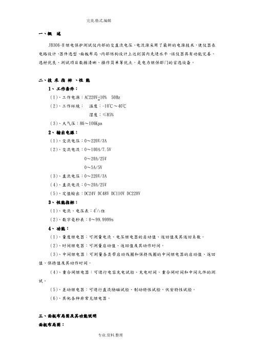
一、概述JB306-H继电保护测试仪内部的交直流电压、电流源采用了最新的电源技术,使仪器在电路设计、器件选型、面板布局、内部结构设计上达到国内先进水平。
该仪器具有功能完善、选材优良、测试项目数据清晰、操作简单等优点,是电力继保部门的首选设备。
二、技术指标、性能1、工作条件:(1)、工作电源:AC220V+10% 50Hz(2)、工作环境:温度:-10℃~40℃湿度:≤85%(3)、大气压:86~106Kpa2、输出电源:(1)、交流电压:0~220V/3A(2)、交流电流:0~100A/7.5V0~20A/25V0~5A/5V(3)、直流电压:0~220V/3A(4)、直流电流:0~20A/25V(5)、定值输出:DC24V DC48V DC110V DC220V3、性能指标:(1)、电流、电压表:41/2位(2)、数字毫秒表:0~99.9999s4、功能:(1)、量度继电器:可测量电流、电压继电器的启动值、返回值及其返回系数。
(2)、时间继电器:可测量启动值、返回值及其动作时间。
(3)、中间继电器:可测量各类带启动线圈和保持线圈的中间继电器的启动值、返回值、保持值及其动作时间。
(4)、重合闸继电器:可进行电容充电试验、充电时间、重合闸时间和中间元件的测试。
(5)、差动继电器:可进行直流励磁试验、制动特性试验、伏安特性试验。
(6)、其他各种非常见继电器。
三、面板布局图及其功能说明面板布局图:功能说明:(1)J1、J2、J3、J4、J5分别为交流、直流电源及其定值输出端子,如面板所示。
(2)X1为电流电压值显示(显示启动值、返回值和额定值),X2数字毫秒表。
(3)S1电源插座, S2电源开关。
(4)T1电源输出选择旋钮,T2定值输出选择旋钮,T3触点状态选择旋钮(其中:示可以用灯来判断动作值及返回值,Ⅰ表示常开触点通电延时合,Ⅱ表示常开触点断电延时开,Ⅲ表示常闭触点通电延时开,Ⅳ表示常闭触点断电延时闭。
综合测试仪设备操作说明书
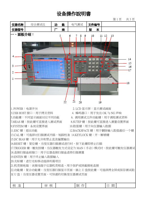
仪器名称 综合测试仪功 能 电气测试文件编号仪器型号厂 商版 本 一、面板介绍:1. POWER :电源开关2. LCD 显示屏:显示测试画面B HOST 接口:用于拷贝资料4. 蜂鸣器口:用于发出OK 与NG 声响5.功能键:不同显示画面对应不同功能6. 调用测试文件功能键:用于调取测试资料7.MEAS 键:按此键可直接进入测试界面8.SUTEP 键:按此键可直接进入测量设置界面9.SYSTEM 键:系统设置界面 10.数值键:用于向仪器输入数据11.ESC 键:退出功能 12.BACKSPACE 键:用于删除输入数值最后一个键 13.CAL 键:可选择对扫描测试开路、短路校准 14.KEYLOCK 键:开、解锁键 15.DC BIAS 键:用于允许和禁止直流偏置输出16.RESET 键:复位键,当变压器扫描测试进行时,按下此键即停止扫描17.TRIGGER 键:触发按键,当仪器触发方式设定为MAN (手动)模式时,按此键可触发仪器测试 18.连接扫描盒前端口:用于仪器连接扫描盒进持扫描测量 19.ENTEN 键:用于终止输入数据输入 20.光标键:进行光标移动选择所需项目21.机壳接地端:该接线端于仪器机壳相连。
用于保护或屏蔽接地连接22.功能键:复合功能键。
当变压器扫描显示页面,插上U 盘按此键,可选择拷全屏或保存测试数至U 盘;当变压器设置页面,可快速的切换变压器测试页面核 准 审 核 制 作 日 期4321567 8 910110 120130140 150 160 170 18192021 22仪器名称 综合测试仪功 能 电气测试文件编号 仪器型号厂 商版 本二、操作说明:1.仪器、扫描盒、治具的连接如下图:23.连接扫描盒前端口:用于扫描盒连接仪器 24.扫描盒:由仪器控制其扫描测量 25.脚踏板开关: 26.综合测试治具27.SCANNER :控制端口,用专用电缆线将扫描盒SCANNER 接口与仪器SCANNER 接口相连接 28.专用电缆线:用于仪器与扫描盒的连接 29.电源线:用于接通220V/50HZ 的电压 30.SCANNER 接口:通过SCANNER 接口控制变压器扫描盒2.仪器的开机:接通220V/50HZ 电源后,按下如图“1”电源开关按键后再按MEAS 键进入变压器测试界面。
接地电阻测试仪使用说明书样本

4102A/4105A接地电阻测试仪使用说明书目录1安全事项------------------------------------------1 2特点----------------------------------------------2 3规格----------------------------------------------2 4部件名称------------------------------------------4 5准备测量------------------------------------------5 6测量方法------------------------------------------5 7更换电池------------------------------------------8 8机壳与背带----------------------------------------91.安全事项本仪器符合以下的标准●IEC 61010-1 CATⅢ-300V.二级●IEC 61O10-2-31●IEC 61557-1, 5●IEC 60529(IP54)●JIS C1304-95为正确使用本测试仪及避免触电的危险,使用前请务必详读本说明书。
在说明书中,遇到特别需要注意事项均以表示,请仔细阅读之: 危险是标示有可能造成触电事故的注意事项,注意是标示可能起仪器损坏或测量误差的注意事项。
为确保安全,以下的注意事项请务必遵守:(1)测试前请先确认量程选择开关已设定在适当的档位。
(2)测试导线的连接插头已紧密地插入端子内。
( 3)主机于潮湿状态下.请勿作接线动作。
(4)在各档位中, 请勿加载超于该量程额定值的电量。
(5)请勿在线接于被测物上时切换量程选择开关。
(6)测试端子间请勿加载超过200安培的交流或直流电压。
(7)请勿在易燃性场所测试, 火花可能会引起爆炸。
测试仪使用说明书

Content1.Introduction / Product Package2.Safety Measures3.Danger of electric shock and other dangers4.Intended Use5.Tester Information6.Preparation for tests6.1 Auto-power on/ switching on 6.2 Auto-power off 6.3 Self-Test7.Conducting Tests7.1 Voltage Test7.2 Single-pole phase test 7.3 Phase Rotation Test 7.4 Trip Test of RCD7.5 Continuity test (Rx) / Diode test 7.6 Resistance test 7.7 Torch Light 7.8 Data Hold 7.9 Buzzer 8.Battery Replacement 9.Technical Data 10. Cleaning and storage 11.Safety advicesReferences marked on testerW arning of a potential danger, comply with instructionmanual.☞Reference. Please pay utmost attention.C aution! Dangerous voltage. Danger of electrical shock.Equipment for working under live voltageContinuous double or reinforced insulation complies with category II DIN EN 61140.Conformity symbol, the instrument complies with the valid directives. It complies with theEMCDirective(2014/30/EU)complies with the Low Voltage Directive (2014/35/EU), StandardEN61243-3:2014T ester complieswith thestandard (2012/19/EU)WEEET he instruction manual contains information and refe-rences, necessary for safe operation and maintenance of the tester.Prior to using the tester (commissioning/ assembly)the user is kindly requested to thoroughly read the in-struction manual and comply with it in all sections. F ailure to read the tester manual or to comply with the warnings and references contained herein can result in serious bodily injury or tester damag.The respectiveaccidentprevention regulations es-tablished by the professional associations are to be strictly enforced at all times1.Introduction / Product PackageThe voltage tester 2200X is universally applicable tester and trip test of RCD.The tester is constructed according to the latest safety re-gulations and guarantee safe and reliable working.The voltage tester 2200X is characterized by the following features:•D esigned to meet international safety standards. EN61243-3:2014 and IEC61010-1• M easurement Category (CAT.) IV 600V, III 1000V• A C and DC voltage test up to 1000Vac and 1500Vdc with LCD •P olarity indication •S ingle-pole phase test • P hase rotation test • T rip Test of RCD • C ontinuity test • R esistance test • A uto-power ON / OFF • T orch light • I P64 (IEC60529)After unpacking, check that the instrument is undamaged.The product package comprises:1 pc Tester 2200X 2 pcs 4mm test tip adapters 2 pcs CAT III/ 1000V test tip cover 2 pcs batteries 1.5V, IEC LR031 pc instruction Manual7.Conducting Tests7.1 Voltage test•Connect both probes to the object under test.• The voltage is indicated by LEDs and LCD • B uzzer sounds when a threshold voltage of 50VAC or approx. 120 VDC is exceeded.•Voltage polarity is indicated in following manner.➘AC: + and – 12V LED are on ➘+DC: +12V LED is on➘-DC: -12V LED is on (and “-“ is shown on LCD)☞ W hen the L2 probe + is the positive (negative) po-tential, the Polarity indication LED indicates “+DC”(“-DC”).☞During voltage test, L or R LED may light up.☞I n case of empty batteries, the ELV LED lights up>50VAC, >120VDC7.2 Single-pole phase test☞ F unction of this test may not be fully achieved if theinsulation condition/ grounding conditions of user or of the equipment under test aren’t good enough. Ve-Single-pole phase test only, but on the voltage test.•H old the tester well in your hand. Connect the “L2 +”probe to the object under test.Single pole LED lights up and buzzer sounds when a voltage of approx. 100V AC or more exists in the object under test. (Pol≥100VAC).7.3 Phase rotation test •L LED and R LED for Phase rotation test may operate on various wiring systems, but effective testing result can be obtained only on three-phase 4-wire system.•H old the tester good in your hand and connect both probes to the object under the test.•Phase-to-phase voltage is indicated by Voltage LEDs.•• •M easurement principle: The instrument detects the phase rising order regarding the user as earth.☞ F unction of this test may not be fully achieved if theinsulation condition/ grounding conditions of user or of the equipment under test is not good enough.7.4 Trip Test of RCD☞ F or voltage tests in systems with RCD (earth leakagecircuit breakers) an RCD can be tripped with a 10mA or 30mA nominal leakage current on single phase AC 230V power system.• C onnect probes “L1” and ”L2” between L and PE of RCD protected system.• P ress simultaneously both of Trip TEST RCD Push-buttons.• The RCD should trip.7.5 Continuity test (Rx) / Diode test T he test circuit/object shall be de-energized before measurement.• C heck for the absence of voltage by conducting a two pole voltage test on the test object.I f the indication “voltage present” appears although the checked part is considered as disconnected, it is recommended to verify additional measures if the measured voltage is an interference voltage or not.4.Intended UseThe tester may be used only under the conditions and forthe purposes for which it was designed. Therefore, obser-ve in particular the safety instructions, the technical data including environmental conditions.5.Tester Information1.Test Probe, L12.Test Tip, L23.Torch Light4.Display5.Torch Light Button / Activation R-measurement6.Trip TEST RCD Pushbuttons7.Main body8.Battery door9.Technical data•V oltage range: 6…1000V AC (40…400Hz), 6…1500V DC(±)•L ED Nominal voltage: 12/24/50/120/230/400/690/ 1000V, AC (40…400Hz), DC(±)•LED tolerances according to EN61243-3•ELV indication LED >50VAC, >120VDC•Response time: < 1s at 100% of each nominal voltage •LCD Range: 6…1000VAC, 1500VDC(±)•LCD Resolution: 1V•LCD Accuracy : ±3%±3dgt (6…1000Vac/1500Vdc)•LCD Overrange indication: “OL”•Peak current: Is<3.5mA (at 1000V)•M easurement Duty: 30s ON (operation time), 240s OFF (recovery time)•Internal battery consumption: Approx. 80mA •S ingle-pole phase test voltage range: 100…1000V AC (50/60Hz)•P hase rotation test: 170…1000V phase-to-phase, AC 50/60Hz•Continuity test: Detection range 0…500kΩ + 50%•R esistance m easurement: 0-1999Ω ±(5% + 10dgt); Resolution: 1Ω•Battery: 3V (IEC LR03 1.5V x 2)•T emperature: -5…40°C operation; -20…70°C sto-rage, No condensation •Humidity: Max 85% RH •Altitude up to 2000m•Overvoltage CAT. III 1000V/ CAT. IV 600V •Standard EN61243-3:2014 and IEC61010-1•Pollution degree 2•Protection: IP 6410.Cleaning and storageT ester does not need any special maintenance if used according to user manual.Remove tester from all test points before cleaning. U se a lightly damp cloth with neutral detergent for cleaning the instrument. Do not use abrasives or sol-vents.D o not expose the instrument to direct sun light, high temperature and humidity or dewfall.R emove batteries when the instrument will not be in use for a long period.2.Safety MeasuresT he testers have been constructed and tested in ac-cordance with the safety regulations for voltage tes-ters and have left the factory in a safe and perfect condition.T he operating instructions contain information and References required for safe operation and use of the tester. Before using the tester, read the operating instructions carefully and follow them in all respects.3. D anger of electric shock and other dangersT o avoid an electric shock, observe the precautions when working with voltages exceeding 120 V (60 V)DC or 50 V (25 V) eff AC. In accordance with DIN VDE these values represent the threshold contact voltages (values in brackets refer to limited ranges,e.g. in agricultural areas).T he tester must not be used with the battery compart-ment openB efore using the tester, ensure that the test lead and device are in perfect working order. Look out e.g. for broken cables or leaking batteries.H old the tester and accessories by the designated grip areas only, the display elements must not be co-vered. Never touch the test probes.-surement ranges and in low-voltage installations up to 1000 Vac/1500Vdc.T he tester may be used only in the measuring circuit category it has been designed for.B efore and after use, always check that the tester is in perfect working order (e.g. on a known voltage source). T he tester must no longer be used if one or more functions fail or if no functionality is indicated. I t is not permitted to use the tester during rain or pre-cipitation.A perfect display is guaranteed only within a tempe-rature range of -5°C to +40°C at relative air humidity less than 85%.I f the safety of the user cannot be guaranteed, the tester must be switched off and secured against unin-tentional use.S afety is no longer guaranteed e.g. in the following cases:•obvious damage•broken housing, cracks in housing• i f the tester can no longer perform the required mea-surements/ tests•stored for too long in unfavorable conditions •damaged during transport •leaking batteriesT he tester complies with all EMC regulations. Never-theless it can happen in rare cases that electric de-or the tester is disturbed by electrical devices. Never use the tester in explosive environment Tester must be operated by trained users only O perational safety is no longer guaranteed if the tes- T he tester may be opened by an authorized service technician only.• C onnect both test probes together or press the Torch Light Pushbutton to switch ON the tester.• C onnect both test probes to the test object. For continuity (up to approx. 500kΩ) the Continuity Test LED – Rx is on and the buzzer is active.• C ontinuity test automatically switches OFF after ap-prox. 30 seconds if no continuity is detected. When tester is OFF, If continuity is detected it will be auto-matically switched on again.7.6. Resistance test Make sure that object test isn’t live.• S witch into resistance measurement by short press of torch light. Connect both test probes to the ob-ject under test. Resistance up to 2k show on LCD display. For resistance less than 30 Ohm buzzer sounds continuously to indicate low continuity.• S econd short press switches into voltage measure-ment7.7 Torch light• P ressing the torch light button will turn on the light and after approx. 30s it will turn itself off.• W hen torch light is on, pressing the torch light button for more than 6s will turn off the torch.7.8 Data HoldU nder data hold mode, The LCD screen will only show the last saved measured voltage value. No auto refresh of LCD screen reading under Data Hold mode whether the voltage tester is connected to energized or non-energized circuit. The LED voltage indicators will always show the actual voltage of the circuit un-der measurement.• A fter pressing the Torch Light push button for more than 2 seconds, the data hold function is activated and replies with a short sound. The LCD screen shows “the last measured value” and sym-bol “HOLD”. The hold function can be deactivated manually by pressing the Torch Light push button again. Function deactivation will be announced with a short sound.8.Battery ReplacementR emove the probes from any testing point, when ope -ning the Battery case. Batteries are empty when the continuity test with both test probes connected cannot be done anymore. A battery symbol in the LCD indica -tes low battery.Follow the procedure below and replace bat -teries with new ones (type IEC LR03 1.5V).• U nscrew the battery door using Philips type screwdriver.•P ull out the Battery door and replace the batteries.Insert new batteries according to the engraving on the Battery door.Control elements1.Buzzer hole for acoustic indication2.Single Pole Test ELV Warning3.Continuity Test4.5. L CD Display indication voltage,polarity and low battery 6.LED’s indicating 12V and polarity 7.Voltage IndicationAccessory1. 4 mm test Tips,2.Plug on cover (GS38)3.Protective cover6.Preparation for tests6.1 Auto-power-on/ switching on • T he tester switches on when it detects continuity, an AC or DC voltage above approx. 6V or a live phase on L2 (single pole test).•It can be switched on with the torch light button.6.2 Auto-power off• T ester is automatically powered off after 30 sec when there is no signal contacted to the probes.• The torch light switches off after approx. 30 sec.6.3 Self-Test• W hen voltage tester is off short both probes L1 and L2, hold probes shorted.• A ll LEDs, all symbols on LCD and buzzer will be on for a 2s.• S elf-test will start automatically when replacing bat-teries.I f some of LEDs is not ON, or some LCD symbols are not ON or Buzzer or Torch light is not ON, the device is not safe for use. Replace the battery and start Self-Test again. If some of these indications are not ON again, the device is not safe for use and must NOT be used.Do not use tester while Self-Test procedure is activated.11. S afety advices•D epending on the internal impedance of the voltagedetector there will be a different capability of indica-ting the presence or absence of operating voltage in case of the presence of interference voltage.•A voltage detector of relatively low internal impe-dance, compared to the reference value of 100 kΩ,will not indicate all interference voltages having an original voltage value above the ELV level. When in contact with the parts to be tested, the voltage detec-tor may discharge temporarily the interference volta-ge to a level below the ELV, but it will be back to the original value when the voltage detector is removed.•W hen the indication “voltage present” does not ap-pear, it is highly recommended installing earthing equipment before work.•A voltage detector of relatively high internal impe-dance, compared to the reference value of 100 kΩ,may not per¬mit to clearly indicate the absence of operating voltage in case of presence of interference voltage.•W hen the indication “voltage present” appears on a part that is expected to be disconnected of the instal--ther means (e.g. use of an adequate voltage detector,visual check of the disconnecting point of the electric circuit, etc.) that there is no operating voltage on the part to be tested and to conclude that the voltage indicated by the voltage detector is an interference voltage.•A voltage detector declaring two values of internal im-pedance has passed a performance test of managing interference voltages and is (within technical limits)able to distinguish operating voltage from interfe-rence voltage and has a means to directly or indirectly indicate which type of voltage is present.Voltage TesterElma 2200XManualElma Instruments A/S Ryttermarken 2DK-3520 Farum T: +45 7022 1000F: +45 7022 1001************7.9 BuzzerPress the …torchlight“ button for 5s to switch the buzzer off or on. The display indicates with “b_O” (buzzer off)and with “b_I” (buzzer on) the status of the buzzer for 2s on LCD.By default the buzzer is on (as well after battery repla-cement).•Re-assemble battery doo r.prior to measurements.。
- 1、下载文档前请自行甄别文档内容的完整性,平台不提供额外的编辑、内容补充、找答案等附加服务。
- 2、"仅部分预览"的文档,不可在线预览部分如存在完整性等问题,可反馈申请退款(可完整预览的文档不适用该条件!)。
- 3、如文档侵犯您的权益,请联系客服反馈,我们会尽快为您处理(人工客服工作时间:9:00-18:30)。
SJC030B兆欧仪中文使用说明书一、产品详细介绍SJC030B型兆欧表是依据EOS/ESD,CECC、ASTM和UL测试规程设计的,用于测量所有导电型、抗静电型及静电泄放型表面的阻抗或电阻。
使用容易,高品质,高可靠度,该仪表还可测量影响电性能的相对湿度和温度。
测量阻抗温度和湿度。
“湿度和温度会影响阻抗,所以必须测量”测量表面阻抗103-1012欧姆/□,测量电阻103-1012欧姆二、产品功能描述三、产品物理特征. 测量阻抗、温度和湿度,符合ESD标准,S4.1,S7.1和S11.111. 03-1012欧姆/□量程,可测试各种材料的电性能。
. 0伏/100伏测量标度,适合于标准规定的工作台面和地面。
. 塑料仪表保护箱,防止仪表受损. 重量轻,只有425g,携带方便. 液晶数码显示,容易使用,读数方便. 自动断电功能,延长电池使用寿命. 自动回零,保证精确度. 平行电极,1磅重探头及内置阻抗探头,均符合ASTM,EOS和CECC标准. 一年质量保修期. NIST追踪,ISO9000保证. 可替换探头,延长使用寿命. V直流电或镍镉充电电池或交流变压器。
.集阻抗、湿度、温度三种测量仪表于一体。
市场上主流重锤式表面电阻测试仪对比:2四、操作手册测量前,首先确保待测表面干净无污染。
1、表面阻抗(1)、平行探头阻抗测量法(Parallel Probe Resistivity Method)平行探头阻抗测量法是符合EOS/ESD-S11.11-1993标准的测量方法,这是一种快速的测量平面均匀材料电阻值的方法。
这种方法也适合于多层材料的测量,但是在阻抗值报告中必须注明测量时的温度和湿度条件。
A、将表放在待测量的物体表面。
B、将开关调到所需的电压位置(10伏或100伏)C、以大约5磅的压力持续按下测量按钮,此时LCD屏会显示出测量的3表面阻抗,温度和相对湿度值,整个测量过程大约为十五秒种。
.表面阻抗单位为欧姆/□.温度单位为摄式.相对湿度单位为百分比在每次测量中,按下测量按钮后,SJC030B表将连续显示修整测量值,松开按钮后约四十五秒内,显示的是最后一个测量值。
(2)、同心环探头阻抗测量法(Concentric Ring Probe Resistivity method)(同心环探头为选购件)将连线插头插入表的两个3.5毫米插孔,并将香蕉插头与同心环探头(选购件)相联。
将探头放在待测试物体表面后,按下按钮约15秒钟后,在液晶显示屏上将显示出正确的温度和相对湿度,正确的表面阻抗值为液晶显示屏上的读数乘以10,单位为欧姆/□。
2、表面电阻测量这个测量方法是符合EOS/ESD-S4.1测量要求来测量独立于接地的两点之间的电阻,用这个测量方法得出的测量结果与被测物体的处理、两个5磅探头之间的距离等因素有关,因此,应选择正确的测量规程,每次在同样要求的测量条件下进行测试。
A、将连线插头插入表的两个3.5毫米插孔,并将香蕉插头与两个5磅重探头相联。
B、按照测量规程将两个探头放置在待测物体表面。
C、选择所需的电压值(10伏或100伏)D、按下开关直到显示出所选的电压值(10伏或100伏),继续按着开关直至所测电阻(单位为欧姆),相对湿度和温度显示在液晶显示屏上。
电阻值范围:10e3=1千欧姆410e4=10千欧姆10e5=100千欧姆10e6=1兆欧姆10e7=10兆欧姆10e8=100兆欧姆10e9=1000兆欧姆10e10=10000兆欧姆10e11=100000千欧姆10e12=1000000兆欧姆不同于其他LED类型的表面电阻测试仪,SJC030B的LCD显示屏会将实测精确值显示出来。
比如:27欧姆(2.7*10e7)将会显示为:2.7 e07 ohms/sq测量的电阻值范围区分:3、表面对地电阻测量这个测量方法是用于测量物体表面一点与表面上另一接地点之间的表面电阻,测量方法符合EOS/ESD S S4.1测量标准。
A、将两条连线的一端分别插入表的两个3.5毫米插孔,然后将其中一条接鳄鱼夹,另外一条与一个5磅重盘形探头相联。
B、将鳄鱼夹子接到所知的接地点上,按照测量要求将盘形探头放在待测物体表面上。
5C、按下测量按钮直至电阻(单位为欧姆)、相对湿度、温度值显示在显示屏上,测量结果符合EIA,EOS/ESD,ANSI,IEC-93,CECC,ASTM 测量标准,对于高阻抗材料的测量时为保证测得高精度测量结果,需注意不要使两引线交叠,不要用手接触探头,引线和被测物体。
五、校准步骤1、范围为103到1012具有精度1%的阻抗电桥。
高精度相对湿度表(Relative Humidity Hygrometer)高精度温度表(High accuracy Thermometer)2、打开表盖,小心切莫损伤电路板上两条连接电源开关的导线。
3、找到电路板右下方三个校正调节器(Calibration Pots)4、使表在这一环境条件下起码1/2小时,取得自平衡后才可开始测试。
5、采用SJC030B表自带的连接线一端连接上鳄鱼夹,另一端香蕉插头。
6、将3.5毫米长的插头插入表的插口。
7、用鳄鱼夹连接电阻器两端。
8、三个校正调节器,最上面的为“湿度”测量,中间的为“阻抗”,最下面的为“温度用小号螺丝刀调节”。
顺时针方向为增加值调节,逆时针方向为降低值调节。
9、按下电源开关,同时比较“温度”,“湿度”和“电阻”值。
10、释放电源开关,并慢慢调节相应的校正调节器。
11、再次按下电源开关,观察LCD显示屏。
12、如需要再校准,可再按下电源开关和调节校正器。
13、盖上表盖并将四个固定螺丝上紧。
14、按下电源开关确定表是否工作正常。
10V范围的精确度:10e3-10e4 +/-9%@RH<90%10e4-10e8+/-5%@RH<90%10e8-10e9+/-9%@RH<90%10e9-10e10+/-25%@RH<60%6100V范围的精确度:10e-10e8+/-5%@RH<90%10e9-10e10+/-9%@RH<60%10e10-10e11+/-15%@RH<50%10e11-10e12+/-25%@RH<40%当湿度与温度在70%与70华氏度以内时,湿度与温度误差在3%与+/-3华氏度;当湿度与温度均超过70%与70华氏度,湿度与温度误差在5%与5华氏度。
六、问题解答1、、为什么说温度和湿度的测量很重要?由于温度和湿度会直接影响被测物体的电特性。
在温度和湿度都较低的条件下,物体的电阻会明显增大,使静电泄放速度缓慢,时间增加,在高湿度条件下,物体表面凝结或吸附一层薄薄的水膜。
这种吸湿性增强了材料的导电性,对于那些能吸收水汽的材料尤其如此。
随着温度的升高,自由电的流动性增大,因此增强了材料的导电性,尤其是那些添加了碳黑、金属氧化物、金属或其他导电物质的材料。
当温度较低的时候,材料会产生内应力,使其中的导电添加物之间距离增加,从而增大其电阻。
因此,必须要了解湿度和温度。
在湿度高的条件下测试一种材料,它可能会通过所有被测指标,但当用户购买了该材料,并在低湿度或温度使用时,它可能会达不到要求,这样就造成了废品和损失。
必须测量和记录温度/湿度的另一个原因是ANSI/ESD协会和欧洲CECC也承认环境温度/湿度的影响,并在他们制订的标准中要求必须测量和记录这些数据。
例如:在ESD DS4.1 ESD防护工作表面,6.2.4节和ESD S7.1-1994材料阻抗参数,地面材料第5.2.4节和5.3.3节均要求,“同时报告测试时的温度和相对湿度”。
7ANSI/EOS/ESD-S11.11-1993静电泄放平面材料的表面阻抗测量第11.0节.B.“报告调节周期,相对湿度和温度。
”必须同时测量和记录这些数据以免发生错误,制造商、经销商和销售人员和用户必须了解环境湿度和温度参数,以免对一些特殊材料拒收或报废。
2、为什么或什么情况下要分别在10伏和100伏条件下同时测量?过去,人们要测量阻抗,必须依照ASTM D264,ASTM 991A或NFPA 56A或99等标。
在这些测量过程中要求测量电压在500或1000伏,对实验人员的安全有一定的影响,因此人们希望用较小的、经济的测量仪器在9伏电压下进行测量。
但在9伏电压下,阻抗值大于107欧姆时精度难以保证,所得到的结果不准确。
最后ESD协会标准化了测量过程。
标准过程规定:在阻抗值大于106欧姆/□时,必须在稳定的100伏电压下测量,阻抗值小于106欧姆/□时必须使用10伏测量。
这一规定在ANSI/EOS/ESD标准DS4.1,S7.1和S11.11中有解释。
3、为什么数码显示优于模拟显示或发光二相管(LED)显示?模拟显示较难读数,LED显示较难确定量级。
4、该仪表可使用充电电池吗?可以。
5、没有外部探头,可以使用该仪表吗?可以,在仪表底部有内置或平行探头,测量值的单位是欧姆/□。
可以快速测量表面阻抗,完全符合ASTM D-257测试方法,以及要求约5磅的压力。
86、当松开按钮时,读数仍在显示,会消耗电池吗?不会。
7、如果连续测量,必须回零吗?不必,该仪表自动回零。
8、什么是RTT、RTG,与阻抗有何关系?RTT是两点间电阻,RTG是一点对地的电阻,电阻是确定产品在实际使用中是否有效的最好办法。
9、当电池电量不足时,还能使用该仪表吗?是的。
如果电池电量不足时仪表显示“low battery”。
但即使在这种情况下,该仪表仍会给出精确的读数。
当电池电量低到不能保证一个稳定的100伏输出时,该仪表就完全不再工作。
此时,电池中仍用一定的电量,可用于对电量要求不高的其他仪器设备。
10、如果测试一种高电阻的材料,测量电压会低于100伏吗?不会,该仪表的变压器在全阻抗量程中都会保持稳定的100伏电压。
10伏电压测试中也一样。
11、如果平行电极坏了,可以换吗?可以。
12、该仪表可以在220伏电压下使用吗?可以,随表提供120伏的接口。
如在220伏下使用,须买一个12伏直流/220伏交流变压器。
13、如果仪表坏了,可以修吗?如果不是由于使用不当或摔碰造成的故障,提供一年保修服务。
914、当仪表从冷的地方带到暖和的地方时,温度变化较大时,必须等半个小时让其适应环境条件。
因此,半个小时后才能正常工作。
15、该仪表的适用范围有哪些?该仪表可用于包括工程制造、保护、质量控制、进货检验,科研以及销售等方面的对任何平面材料的测试。
16、该仪表可用于哪些行业?胶片、医学、超净间、电子自动化、制药、科研及涂料等。
17、使用该仪表可测试何种材料?任何静电泄放材料,包括电阻大于1000欧姆的导体材料均可。
如地垫、桌垫、防静电地板砖、表面涂层、地板涂料、袋子、容器、工作服、鞋套、脚环、腕带、接地线等。
