2020年(情绪管理)GRT气体继电器压力释放阀自动测试仪
德尔塔4000自动电 funeral性因素测试装置配件说明书
AccessoriesTESTING LARGE SPECIMENSThe resonating inductor expands the capacitance range of the DELTA automated insulation power factor test sets. The resonating inductor is a self-contained, air-insulated tool which allows the user to perform capacitance and dissipation factor tests on high-capacitance items such as large motors, large generators and long cable runs.A manual tuning wheel on the resonating inductor varies the inductance to tune the parallel circuit for minimum load current.Resonating Inductor includes:High-voltage interface cable, 8 ft (2.4 m) Ground interconnect lead, 8 ft (2.4 m)Inductor return cable, 8 ft (2.4 m), with connector Ground lead, 15 ft (4.6 m)Cable bag Instruction manual30012-1330991-11001-8024702-518313670600a_UGSPECIFICATIONSMaximum Capacitive Load1 µF , at 60 Hz - 12kV1.2 µF , at 50 Hz - 12 kV 1.33 µF , at 45 Hz - 12 kV(from DELTA4000 variable frequency source)Dimensions 38.7 H x 21.4 W x 25.3 D in. 983 H x 543 W x 641 D mm Weight280 lbs (127 kg)Megger provides adapter kits that offer solutions for users who already own an older style or competitor’s resonating inductor and need to connect to a DELTA4000. Our C/N 1002-455 includes:High-voltage interface cable, 8 ft (2.4 m) Inductor return cable, 8 ft (2.4 m), with connector Adapter kit box, unterminated Connector assembly30012-141001-8021002-231-11002-506Cat. No. 670600-1Cat. No. 1002- 455For more information about these products,visit our website FIELD & LAB CALIBRATIONThe CAL4000 is designed for use in performing calibration adjustments of the DELTA4000 series of instruments. Together with provided software, it allows for proper adjustment of critical measurements within the DELTA4000 including: tan delta (PF), capacitance, voltage, current, watts and other measurements. Operators are able to perform the calibration adjustments within a 20 to 30 minute timeframe. This tool does not replace a traceable report, only a method to bring the DELTA4000 to within specified accuracy.When field testing, the reliability of test results is critical in determining the true condition of the transformer or related asset. In order toconfirm proper operation of the DELTA4000 and its nominal accuracy, Megger has developed a set of capacitors that provide this confirmation of results. The capacitors come in a set of three where two capacitors contain one nominal tan delta (PF) value as to simulate a typical test result. The third capacitor is of a higher value and serves a second purpose as a TTR add-on function capability. All units include a field transit case for easy store and protection.Capacitors can be purchased individually should the specific need arise.SPECIFICATIONS HV Capacitors10 nf, 10 kV – C/N 36610100 pf, 10 kV – C/N 36610-11000 pf, 10 kV – C/N 36610-2Transit case for capacitor with set of 3 above C/N 36610-CCCat. No. 2002-137Cat. No. 36610-KIT2Shown here: TTR cap, 2 ref caps, test hook, test clip, transit caseHV Reference Standard, Capacitance and Tan Delta (PF)This is typically used by laboratories where traceable calibration results for capacitance and tan delta (PF) are required. The reference standard can be used with the DELTA4000 and any related test equipment that performs similar testing as the DELTA4000. The reference standard offers a maximum test voltage of 10 kV. To confirm proper DELTA4000 accuracy at critical values, this unit comes with six switch selectable tan delta (PF) test points. It is supplied with a report traceable to NIST.SPECIFICATIONS Rated Voltage 10 kV maximum (with oil)Nominal CapacitanceHigh to low 100 pF (±1.0%)(internal SF6 filled capacitor, 10 psig)Tan delta (PF) (at 0 position)High to low <0.005% (50ppm)Nominal tan delta values (switch positions)0.0%, 0.105%, 0.32%, 1.05%, 3.2%, 10.5%Weight 18 lbs (8.4 kg)Dimensions11 x 9.5 x 16 in. (28 x 24 x 41 cm)Cat. No. 670500-1FIELD AND LAB OIL TESTINGAs an optional accessory, the field oil cell allows spot testing of oil while in the field without the delay required when sending samples to the lab. This cell is also useful for validation of oil taken from a tanker prior to filling a transformer, and associated assets. The oil cell has added value when validation of the condition/operation of a DELTA unit is required.SPECIFICATIONSCell Type3 terminalMaximum Voltage 2 kV empty; 10 kV with insulating oil Volume 0.6 L (20 fl. oz.)Gap Space 0.35 in. (0.9 cm)Weight6 lbs (2.7 kg)Temperature Limits Field oil cell+2° C to +80° CThe high-temperature lab oil cell is of the identical construction/dimension as the field oil cell with the exception of the insulated spacers. The difference is the plastic insulators of the lab oil cell are replaced with Borosilicate glass, which allows operation under higher temperatures with no significant effect on results. The lab oil cell is designed to test to ASTM D924, IEC250, and other related standards. Because this glass can break easily, it is not recommended for rough field use. It does include a rugged transit case to ensure safe transport.SPECIFICATIONS Cell Type3 terminalMaximum Voltage 2 kV empty; 10 kV with insulating oil Volume 0.6 L (20 fl. oz.)Gap Space 0.35 in. (0.9 cm)Weight6 lbs (2.7 kg)Temperature Limits High-temp lab cell+2° C to +105° C Cat. No. 670511Cat. No. 1004-716All accessories above are includedFor more information about these products,visit our website FACTORY AND FIELD RATIO TESTINGExpand your testing capabilities with the latest transducer available for the DELTA4000. Accurate ratio and phase measurements are a sure-fire way to verify CVT stack integrity, as traditional capacitance measurements will not change significantly when there is a problem. With ±0.1% accuracy, the HV CVT/VT Ratio transducer provides factory accuracy while testing in the field.The HV CVT/VT ratio comes complete with all the accessories you will need to connect to terminal blocks of CVTs or PT/VTs.Note: Requires Delta 4010B HV Unit for ±0.1% AccuracyMeasuring the ratio of power or distribution transformers is now easier than ever with the new HV TTR Transducer for the DELTA4000. This latest accessory utilizes the latest clamps for secure connection to the top of bushings, and provides an easy-to-follow connection diagram and steps to complete the test on the back of the accessory. With a ±0.1% accuracy, this accessory turns the DELTA into a true multifunction instrument.Note: Requires Delta 4010B HV Unit for ±0.1% AccuracySPECIFICATIONS Voltage Range 1 - 600 V Frequency Range 1 - 500 Hz Ratio Accuracy ± 0.10%Phase Accuracy± 3 minSPECIFICATIONS Voltage Range 1 - 12,000 V Frequency Range 1 - 500 Hz Ratio Accuracy ± 0.10%Phase Accuracy± 3 minFor safe testing procedures, Megger offers a high-intensity flashing strobe complete with a 60 ft (18 m) detachable cable. A ruggedconnector on both ends enables typical field use. The cable used is oil resistant and designed for varying temperature condition.The following can be purchased separatelyHV strobeCat. No. 90009-210Detachable cable, 60 ft (18 m)Cat. No. 1004-532SAFETY EQUIPMENTCat. No. 1004-639For hands-free operation, Megger offers a foot-operated safety switch. It comes with a 6.6 ft (2 m) rugged cable and an industrial ratedmechanical foot pedal. This is a convenient accessory for operation of the DELTA4000 while performing routine testingCat. No. 1001-852TRANSIT CASESSturdy protection for your DELTA4000 and its test leads is critical. Megger offers a rugged, moisture-proof solution for storage and transport of your investment. This case is made of a tough plasticdesigned for harsh environments. Its foam-padded interior offers extra protection for your valuable equipment in an organized manner.SPECIFICATIONS Dimensions27 x 27 x 16 in. (69 x 69 x 41 cm)Dust and water protection rating IP54Weight37 lbs (17 kg) emptyCat. No. 2005-115TRANSIT CASESIf a rugged transit case is not needed or desired, a soft-padded case is available to carry your DELTA4000. This case is convenient to store the unit in when not in use yet durable enough to transport the DELTA4000 between jobs.This carry case is NOT intended for transporting instruments via commercial carriers; its intention is for local transit from location to locationSPECIFICATIONSDimensions 11 x 12 x 20 in (28 x 30.5 x 50.8 cm)Weight1.6 lbs (0.7 kg)Transport CartFor substations and related environments where terrain is rough, and DELTA4000 is required to be moved to various testing locations, Megger offers a collapsible trolley/cart. The DELTA4000 can be setup on the cart for easy testing and allows for convenient movement throughout the testing area. The cart is equipped with a sturdy, wide handle for comfortable steering and control.SPECIFICATIONS Dimensions 20.5 D x 59 H x 24 W in. (52 x 150 x 61 cm)Weight 30 lbs (13.6 kg)Folded dimensions11 D x 37 H x 24 W in. (28 x 94 x 61 cm)Cat. No. 2001-766Cat. No. 2009-071For more information about these products,visit our website Testing transformers requires the performance of specific tests where additional apparatus is needed. Megger offers a kit that includes the most commonly used tools.A J” probe bushing adapter probe 30917G 6m (20ft) non-insulating shorting lead2014-136-20B Bushing tap adapter, 1 in. (2.5 cm)30918-100H Bushing tap adapter – ABB (older style bushings)2006-375C Bushing tap adapter, 0.75 in. (1.9 cm)30918-000I Bushing adapter, female-to-female banana jack 90014-353D Thermometer – hygrometer – clock 670504J Bushing adapter, male to female90021-216E Hot collar strap (set of 3)670505KTemperature humidity probe with 20 ft (7 m) lead2002-138F3m (10ft) non-insulating shorting lead2014-136-10ACCESSORY KITSABCDEFGHIJKDATA MANAGEMENT SOFTWAREPowerDB Pro software is a relational database with formatted test forms for data entry and reporting. Over 300 test forms are comprised in the standard forms library. Data is entered, or gathered, by remote users in “field” databases and then merged into a central master database for access by all users. Data can be imported from various sources, acquired directly from test instruments, or entered manually. Assets are efficiently organized in the database and can be searched for by location, serial number or asset ID number.Another optional software program is PowerDB Advanced, which gives customers access to all forms within PowerDB Pro but without the relational database. The forms and ability to edit the results allow customers easy access to useful forms that can be used as a platform to develop a reliable test program.PowerDB Pro software on USB dongleCat. No. DB1001S-A PowerDB Pro software via soft key Cat. No. DB1001-A PowerDB AdvancedCat. No. DB1011Extended Warranty ProgramAn extended warranty is offered as a safeguard against unexpectedinstrument repairs. This also helps to ensure that repair costs are covered without undue financial stress. Megger offers an extended warranty beyond the standard 12-month increments of 6 additional months,followed by 12 months, 24 months and 36 month terms. Customers are only responsible for proper return to Megger Authorized Centers, and for their shipment back.Additional 6-month product warranty Y6-WARRANTY Additional 12-month product warranty Y12-WARRANTY Additional 24-month product warranty Y24-WARRANTY Additional 36-month product warrantyY36-WARRANTYEXTENDED WARRANTYDELTA_Accessories_BR_en_V07The word ‘Megger’ is a registered trademark Copyright © 2016Megger。
GRT—91、92气体继电器压力释放阀自动测试仪
安全指南尊敬的用户,感谢您选用我们的产品,为便于仪器能正常使用,请先阅读下列说明:1.请遵守仪器和说明书上标示各种警告及说明事项;2.清洁仪器时,请先关闭电源,拔下电源插头;3.为避免损伤仪器底部,请勿将本产品放置于不平物和表面上;4.请使用说明书指定的电源为仪器供电;5.切勿将任何物体插入仪器内。
机内有高压、变压器油,避免导致电击、短路或火灾;6.请在看懂本说明书后才使用仪器;7.请妥善保存本说明书,以便随时查阅;注意:发生下列情形时,请关闭电源和拔下电源插头,并与维修人员联系,我们将及时地帮助您解决问题。
1.电源线损坏或磨损;2.仪器遭受雨淋(或其它液体);3.虽按正确方法使用,但仪器仍无法正常工作;4.曾进行不正确的调整;5.本产品跌落或损坏;6.本产品性能无法完全发挥效能。
RLC-8(QYG)气体继电器压力释放阀自动测试仪主要特点RLC-8QYG型气体继电器压力释放阀自动测试仪是在RLC-7QYG2型半自动校验台的基础上改进的高科技专利新产品,其主要特点是:1.流速测量模拟变压器内部故障情况,采用压差法测脉冲流速的原理是经原能源部电力司组织全国专家技术评审认为:测试原理先进,测量离散率小,误差符合要求,携带方便、适于现场使用,是全国急需的试验设备,很有推广使用价值。
2.采用东北、华中、云南的综合计量基准,可在全国范围内适用。
新设计有两种误差修正装置,使测量精度符合国内外标准校验台校验要求。
3.功能更多、应用范围更广。
除具有直接测试QJ-25、QJ-50、QJ-80、QI-50W、QJ-80W型继电器流速、容积、密封等检验项目外,还可满足变压器YSF-25、50、80、130型压力释放阀进行开启、关闭压力试验。
4.本测试仪自动化程度高。
采用微机测控、数码显示,操作试验时除人工配合回油外,实现了测量、参数调整、控制操作、记录打印自动化。
5.本测试仪技术性能完全可代替固定式油泵法校验台使用,并具有体积小,便于携带、满足现场试验需要,节约设备和试验室大量投资等优点。
变电检修工作总结(精选8篇)_变电检修管理工作总结
在这一阶段的培训里,让我学到了很多知识,在各位师傅的悉心指导、栽培下,我各方面都有了一定的提高。
同时自身也存在不足,还有很多知识需要摄入,在下面的培训中,我要更加主动地、虚心地多学习,多请教,自觉遵守现场劳动纪律及各种规章制度,积极主动帮组师傅完成各项工作,使自己不断得到更多知识。
第7篇:变电检修4.1.1选择题下列每题都有4个答案,其中只有一个正确答案,将正确答案填在括号内 1 2 3 4 5 6 7 8 9 10 11 12 13 14 15 16 17 18La5A1001 我们把两点之间的电位差称为()。
(A)电动势(B)电势差(C)电压(D)电压差 La5A1002 电源电动势的大小表示()做功本领的大小。
(A)电场力(B)外力(C)摩擦力(D)磁场力 La5A1003 力的三要素是指力的大小、方向和()。
(A)强度(B)单位(C)合成(D)作用点La5A1005 在30Ω电阻的两端加60V的电压,则通过该电阻的电流是()。
(A)1800A(B)90A(C)30A(D)2A La5A1006 在一电压恒定的直流电路中,电阻值增大时,电流()。
(A)提高测量精度(B)确定测量范围(C)防止二次过负荷(D)保证人生安全 Lb5A2043 (A)(B)(C)(D)(A)(B)(C)(D)(A)(B)(C)(D)(A)(B)(C)(D)(A)(B)(C)(D)(A)(B)(C)(D)A39 40C D41 42 43 44 45 464.1.2判断题判断下列描述是否正确,正确的在括号内打“√”,错误的在括号内打“×”。
1 2 3 4 5 6 7 8 9 10 11 12 13 14 15 16 17 18 19 20 21 22 23 24 25 26 27 28 29 30 31 32 33 34 35 36 37La5A1001La5A1002La5A1003La5A1005La5A1006La5A1007La5A10 08La5A2009La5A2010La5A2011La5A2012La5A3013La5A3015La5A3016La5A1017La4A1018La4A1019La4A2020La4A20 21La4A302238 39 40 41 42 43 44 45 46第8篇:变电检修个人工作总结。
河北工业大学科技成果——油罐呼吸阀压力自动测试仪
河北工业大学科技成果——油罐呼吸阀压力自动测试仪项目简介呼吸阀是安装在固定顶储罐或运输油罐上的通风装置,可减少油品蒸发损耗,控制储罐压力平衡,是必不可少的安全装置。
呼吸阀的压力是最重要的安全指标,主要检测四个压力值:正压开启压力,正压关闭压力,负压开启压力和负压关闭压力。
现有的压力测试装置一般采用气泵作为压力源,以压力表或数字压力计对这些压力进行检测,不仅体积庞大而且操作不便,更不能完成自动、多只和多批次的检验和测试。
本测试仪是一种新型测试仪,摒弃了气泵等笨重设备,其主要技术特点:采用新的加压/减压方式,所有部件集中在一个便携装置内,体积小巧;采用计算机控制方式,可在几秒钟内一次自动完成呼吸阀的四个压力值的测试;可以对呼吸阀进行任意循环、多只、多批次的自动测试,检验测试效率高;采用高精度压力传感器,高精度USB 数据采集卡,确保测试的高精度;计算机操作界面采用LABVIEW编程,操作简单,判定直观;可以对测试数据存储和分析。
市场前景根据有关标准,各种呼吸阀在出厂前和使用过程中都必须经过检验和定期检测。
除生产企业外,使用呼吸阀的主要行业是:石油、石化行业;铁路、船舶、公路运输;质量监督部门对产品质量监督;环保部门呼吸阀的污染物排放控制;消防部门的安全检测;呼吸阀生产企业对出厂产品进行的测试;呼吸阀研究机构。
规模与投资本项目是一种机电、计算机测控一体化产品,包括测试设备和计算机软件。
对于年产100台的规模,投资50万元即可。
生产设备常规的机加工能力(车、铣、钎),也可以外协加工;电路板焊接、组装、调试。
效益分析根据不同的需求,本项目有许多不同的型号产品,如测试运输罐呼吸阀的小型测试装置,用于测试固定储罐的中型装置以及多只呼吸阀的大型装置等。
与同类型产品相比,本项目成本很低,但性能很高,根据不同型号,每台产品售价一般为3-20万元。
合作方式合作开发、技术转让。
释放装置在线功能检查报告(中英文)
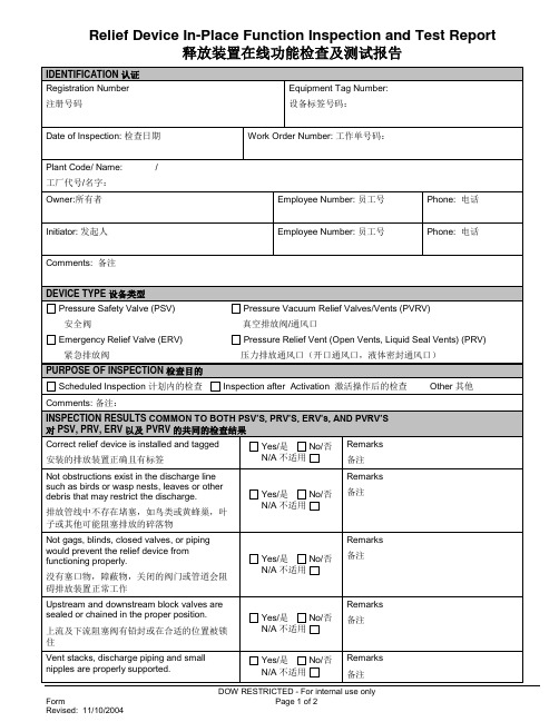
Remarks
备注
Relief device doesnot leak. (Consider use of ultrasonic detection for leak through).
排放装置没有泄漏处(考虑使用超声进行探测)
Yes/是No/否N/A不适用
Remarks
紧急排放阀压力排放通风口(开口通风口,液体密封通风口)
PURPOSEOF INSPECTION检查目的
ScheduledInspection计划内的检查Inspection afterActivation激活操作后的检查Other其他
Comments:备注:
INSPECTION RESULTS COMMON TO BOTH PSV’S, PRV’S, ERV’s,AND PVRV’S
整定压力最初测试:起跳压力为
AdjustmentRequiredYes/是No/否N/A不适用
需要调整
Adjustments completedYes/是No/否
完成调整
Final Test: Pops atPSIG
最终测试:起跳压力为
Registration Number (GEMTS or MMS Equivalent):
Work Order Number:工作单号码:
Plant Code/Name:/
工厂代号/名字:
Owner:所有者
Employee Number:员工号
Phone:电话
Initiator:发起人
Employee Number:员工号
Phone:电话
Comments:备注
DEVICE TYPE设备类型
没有塞口物,障蔽物,关闭的阀门或管道会阻碍排放装置正常工作
GE ADTS 505 高精度气动测试设备说明书
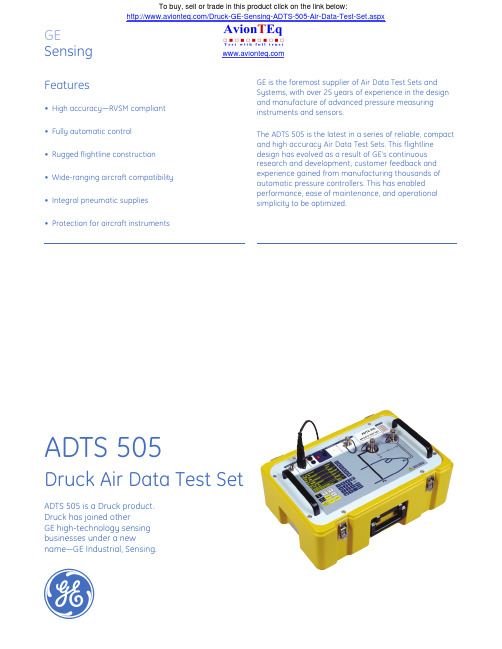
GESensingDruck Air Data Test Setg•High accuracy —RVSM compliant •Fully automatic control •Rugged flightline construction •Wide-ranging aircraft compatibility •Integral pneumatic supplies •Protection for aircraft instrumentsGE is the foremost supplier of Air Data Test Sets and Systems, with over 25 years of experience in the design and manufacture of advanced pressure measuring instruments and sensors.The ADTS 505 is the latest in a series of reliable, compact and high accuracy Air Data Test Sets. This flightline design has evolved as a result of GE’s continuous research and development, customer feedback and experience gained from manufacturing thousands of automatic pressure controllers. This has enabled performance, ease of maintenance, and operational simplicity to be optimized.FeaturesADTS 505 is a Druck product.Druck has joined other GE high-technology sensing businesses under a newname—GE Industrial, Sensing.ADTS 505To buy, sell or trade in this product click on the link below:/Druck-GE-Sensing-ADTS-505-Air-Data-Test-Set.aspxHigh AccuracyCompliant with RVSM (Reduced Vertical Separation Minima) requirements, the ADTS 505 is a precisiontwin-channel Ps and Pt pressure control test set for the accurate calibration/verification of civil aircraft pitot statics.It utilizes advanced micro-machined, piezo-resistive and resonant silicon sensors, developed by GE specifically for high accuracy measurement applications. This technology provides excellent thermal and long term stability.Suitable for use with a wide range of fixed or rotary wing civil aircraft, the ADTS 505 enables vital flight instrumentation such as Altimeters, Airspeed Indicators, Rate of Climb Indicators, Mach Meters and Air Data Computers to be quickly and accurately tested on the flightline.User FriendlyThe sophisticated, yet user-friendly display is fully programmable for a range of test requirements. It can be configured, with limits and preferred units of measurement, for individual aircraft types. The level of information displayed can be determined by the operator to suit the particular task at hand.Advanced FunctionsIn addition to the standard pitot-static functions of the ADTS 505, there are many additional advanced features which include automatic go-to-ground, leak test mode and device under test protection limits amongst others. This enables the operator to undertake flightline testing accurately and efficiently, without compromising safety standards.Cost EffectiveHighly portable, quick and easy to use, the ADTS 505 is also designed for low maintenance, with a recommended 12 month recalibration interval. Operational productivity is optimized and aircraft downtime is minimized.Fully Automatic ControlThe ADTS 505 has fully automatic control by means of the menu-driven high contrast, electro-luminescent display and tactile membrane keypad. The desired altitude, airspeed or rate of climb can be input, and the ADTS 505 will automatically generate and continuously maintain the desired value.A choice of units is provided for Altitude, Airspeed, Rate of Climb, Engine Pressure Ratio and other related test functions. Control and measurement is available for these parameters as well as Static, Pitot and Calibrated Airspeed.Testing With ConfidenceProtection for the aircraft instruments under test includes a power failure protection feature, which, in the event of an interruption to the electrical supply, locks the pneumatic system and allows safe restoration to ambient ground conditions.The ADTS 505 will operate with leaking systems, which in practice can often occur. The required aim value is maintained, enabling the test to be completed.Easy Flightline OperationThe self-contained ADTS 505 simplifies accurate and RVSM compliant pitot-static testing for a wide range of civil aircraft. Featuring a highly compact and lightweight yet rugged construction, it enables single-handed portability for convenient use on the flightline. Integral Pneumatic SuppliesMatched pressure and vacuum pumps are included within the ABS case, which also provides storage for the pneumatic test hoses supplied with AN4 aircraft connections. The ADTS505 is conveniently powered from any aircraft or national single phase supply, with no user switching required.Weighing just 15 kg (33 lb), the compact ADTS 505 offers a convenient yet high performance solution for responding quickly to pitot static and pressure related Air Data Test requirements on the flightline.ADTS 505 SpecificationParameter Operatin g Resolutio n Accuracy Repeatability rangeAltitude-609 to 18288 m(1)0.30 m 0.91 m (3 ft) at ±0.30 m (±1 ft) (-2,000 to 60,000 ft)(1 ft)seal level(2)2.13 m at 9144 m(2)±0.60 m (±2 ft)(7 ft at 30,000 ft)8.83 m at 18288 m(2)±1.82 m (±7 ft)(29 ft at 60,000 ft)Static 35(3) to 1355 0.01 mbar ±0.1 mbar ±0.05 mbar Sensor mbar abs (0.000 inHg) (±0.003 inHg) (±0.0015 inHg)(1 to 40 inHg)Airspeed20 to 650 knots(4)0.1 kts ±0.5 kts at 50 kts±0.4 kts Airspeed0 to 2500 mbar 0.01 mbar±0.1% reading0.05 mbar (Qc) diff (1 to 74 inHg) (0.0001 inHg)±0.125 mbar rising to0.17 mbarRate 0 to 1829 m/min(5) 0.30 m/min±2% of value ±0.5%of Climb(0 to 6000 ft/min)(1 ft/min)(measurement) Mach 0.6 to 2.80.001Better than 0.0050.001 risingto 0.005 Engine 0.1 to 100.001Better than 0.005PressureRation(EPR)1.105,000 ft (32004 m) available (measure mode).2.Accuracy at ambient 5°C to 35°C (41°F to 95°F) for 0°C to 50°C (32°F to 122°F) x 1.53.35 mbar (1 inHg) lowest calibration point. (Will measure below this value.)4.Limits settable to prevent excessive Mach. (Civil limit Mach 1).5.To 9144 m (30,000 ft) into 4 litres. Higher altitudes at lower rates available.The ADTS 505 is housed in a rugged weatherproof case, complete with internal pneumatic pumps for pressureand vacuum generation. Automatic control is implemented by simple menu instruction and keypress at the front panel.Scaling Factors•Altitude: ft, meters•Airspeed: knots, km/hr, mph•Rate of Climb: ft/min, m/min, m/s, hm/s•Others: mbar, inHg, inH2O, mmHg, kPa, hPa, psiRate Control/Indication•Roc: Rate of Climb•Rt Ps: Rate of Static•Rt Pt: Rate of Pitot•Rt Qc: Rate of Pt_Ps•Rt CAS: Rate of calibrated airspeed•Rt EPR: Rate of engine pressure ratioOverpressureNegligible calibration change with up to 1.25 x full scale (FS) overload applied.Calibration StabilityBetter than 0.005% (Ps) and 0.08% (Qc) FS per annum. RecalibrationSimple keypad instruction. 12 month interval suggested. Use of primary standard pressure reference (e.g. Ruska Primary Pitot Static Tester model 2468) is recommended. DisplayLarge area, 1/4 VGA, high contrast, electro-luminescent display. 96 mm x 73 mm (3.7 in x 2.8 in), 320 x 240 pixels. ResponseTwo readings-per-second display value update.Power Supplies•90 to 132 VAC at 47 to -440 Hz, 180 to 265 VAC at47 to 66Hz auto-selection•Rating 200 VAPower Failure ProtectionSystem locks, and a manual let-down feature is provided. Self TestIntegral test routines and reporting for both electrical and pneumatic systems.Temperature Range•Calibrated: 5°C to 35°C (41°F to 95°F)•Operating: 0°C to 50°C (32°F to 122°F)•Storage: -20°C to 70°C (-4°F to 158°F)SealingWeatherproof in operating mode (lid removed). Humidity0 to 95% non-condensing. “Tropicalized” specification. Shock/VibrationDesigned to meet MIL-T-28800 Class 2.ConformityEN61010, EN61326. CE marked.Physical•Weight 15 kg (33 lb) nominal•Dimensions (including lid): 265 mm x 520 mm x 355 mm (10.4 in x 20.5 in x 14 in)CaseABS moulded case with removable lid and storage for accessories.ADTS 505SpecificationPneumatic ConnectionsAN4 for Ps and Pt, both color-coded.Supplied with mating (approximately) 2 m (6 ft) long flexible hoses with AN4 fittings at one end.Pneumatic SuppliesIntegral pressure and vacuum pumps capable of generating the following supply rates:•1829 m/min (6000 ft/min) into a 4 litre volume at 9144 m (30,000 ft)•300 knots/min into a 2 litre volume at 650 knots •Water/moisture content is vented automatically.AccessoriesAC power lead—2 m (6 ft) length approximately. Ps and Pt hoses—2 m (6 ft) lengths approximately. Operators manual and calibration certificate also supplied asstandard.Calibration StandardsInstruments manufactured by GE are calibrated against precision calibration equipment traceable to international standards.Ordering InformationPlease state the following:1.ADTS 5052.Any special requirements。
Honeywell iSeries 智能气体传感器诊断测试说明书
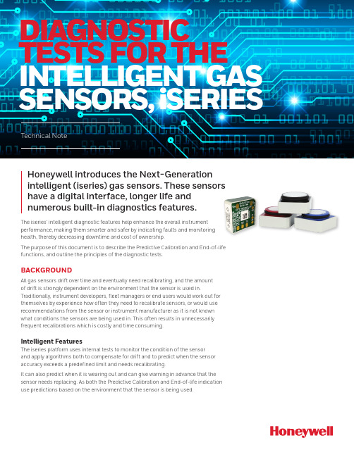
DIAGNOSTIC TESTS FOR THE INTELLIGENT GAS SENSORS, iSERIESTechnical NoteHoneywell introduces the Next-Generationintelligent (iseries) gas sensors. These sensorshave a digital interface, longer life andnumerous built-in diagnostics features.The iseries’ intelligent diagnostic features help enhance the overall instrumentperformance, making them smarter and safer by indicating faults and monitoringhealth, thereby decreasing downtime and cost of ownership.The purpose of this document is to describe the Predictive Calibration and End-of-lifefunctions, and outline the principles of the diagnostic tests.BACKGROUNDAll gas sensors drift over time and eventually need recalibrating, and the amountof drift is strongly dependent on the environment that the sensor is used in.Traditionally, instrument developers, fleet managers or end users would work out forthemselves by experience how often they need to recalibrate sensors, or would use recommendations from the sensor or instrument manufacturer as it is not knownwhat conditions the sensors are being used in. This often results in unnecessarilyfrequent recalibrations which is costly and time consuming.Intelligent FeaturesThe iseries platform uses internal tests to monitor the condition of the sensorand apply algorithms both to compensate for drift and to predict when the sensoraccuracy exceeds a predefined limit and needs recalibrating.It can also predict when it is wearing out and can give warning in advance that thesensor needs replacing. As both the Predictive Calibration and End-of-life indicationuse predictions based on the environment that the sensor is being used.Definition of Diagnostic TestsPredictive Calibration: The calibration process can be very tedious, costly and a time-consuming process. With this function, sensors can predict in advance whenits accuracy is becoming too poor to give a reliable reading. This function helps to identify exactly when a recalibration is required.The sensor can estimate the time to recalibration up to six months in advance. Recalibration intervals will be typically at least twice as long as for conventional sensors and will adapt depending on the environment – with sensors used in more benign environments needing less frequent calibrations than those in aggressive ones.The user can configure the accuracy limit of the sensor, and this will determine the interval at which the calibration is needed. In other words, the tighter the accuracy value, the more frequent calibration needed.The user can therefore trade off accuracy against recalibration interval. There is also a configurable built in fixed interval recalibration countdown timer for applications where legislation requires calibration at certain intervals.End-of-Life: The lifespan of a sensor depends mostly on the environmental conditions at which the sensor is exposed. With this function, the sensor can predict in advance when its sensitivity is falling too low to give a reliable and accurate reading. When the End-of-life function is triggered, the sensor automatically warns the instrument via a set of fault flags sent together with the gas reading. If the fault is detected the instrument can warn the user to stop using the sensor.How was the design of the sensor optimised?Honeywell engineers performed finite element analysis of the water management and electrolyte distribution within sensors and gained an extensive understandingof the optimum designs for retaining the electrolyte in the right place at the right concentration.Subsequently, safety operating area charts were developed based on a combination of fundamental physical theory, modelling and experimental verification to show how sensors will perform and withstand over the full temperature, humidity and time.To validate that the sensor will last in real-world applications, an environmental database was obtained. The database contains hundreds of locations around the world, with temperature and humidity data for 10 years with two hourly resolution. The knowledge of use cases for sensors was combined, for example time spent indoors and outdoors, charging to provide input data on the actual conditionssensors are exposed to in the real world. This information was fed into the models to predict how long sensors will last and how their performance will change in real world conditions, and to assist us in optimising the sensor design for maximum performance and life.The environmental performance data was generated by storing sensors in a rangeof environmental conditions over a two-year period. There were more than 8000 individual gas responses recorded for each gas typeDuring this period, the sensors were tested to generate different databases corresponding to the performance of the sensor at particular environments.The resulting predictive algorithm keeps track of the electrolyte concentration and environmental conditions over time and extrapolates this data with a linear regression in order to accurately predict when does the sensor need to be calibrated or when does the sensor is about to reach its lifespan.How does the predictive model for EoL and Predictive Calibration works?To estimate the EoL and Predictive Calibration, a 30-day time period is defined. During this period, the sensor will keep track of the environmental changes. The model works under the assumption that the sensor will be exposed to similar conditions.For instance, if the sensor has been in an extremely hot and dry environment, the predicted model will calculate the corresponding water loss as if the conditions remained the same; giving warning to the user in order to prevent further dry out. Figure 1 shows how the electrolyte concentration and predicted electrolyte concentration vary for a sensor in an extreme environment. The environment chosen corresponds to a challenging environment for the sensor to survive: during winter, outdoor temperatures can be -40°C or less, and in a heated unhumidified buildingor car, the relative humidity can be extremely low due to the very low water content of the cold outside air. Therefore, a sensor which spends part of the day indoors and part outdoors (a typical ‘field worker’ use case) not only gets very dry in winter but is also expected to function at very low temperatures.A perfect prediction (theoretical) would follow the dashed black line. In other words, the predicted days to recalibration would be exactly equal to the actual days to recalibration.The solid black line shows the true electrolyte concentration, which gets dry (high concentration) each winter but recovers to some extent each summer. The yellow line shows how the concentration has been predicted. The historical relative humidityis calculated from the average of another 30 days prior to that. As the prediction is made over a longer time, it becomes less accurate, mainly because the historical environmental conditions become less representative of the future conditions. How often does the sensor updates the EoL and Predictive Calibration?The diagnostic test runs automatically every 24 hours. However, the test is only performed when the sensor is in sleep mode, so it is highly recommended to change the sensor to sleep mode whenever it is not in use (otherwise the End of Life and Predictive Calibration estimations will not be updated/recalculated, leading to non-accurate results).The sensor needs to be in sleep mode at least two minutes per day, so it can update the EoL and Predictive Calibration values.What technique is used for the diagnostic tests?For this test, a smart indicative gadget is used as a diagnostic electrode. Thenan electrochemical technique called square wave voltammetry is applied to the electrode.The technique is a linear potential sweep voltammetry that uses a combined staircase potential and a square wave, which has the advantage of having better peak definition and location than conventional cyclic voltammetry or staircase voltammetry.The diagnostic test is performed to determine the electrolyte concentration of the sensor.Figure 2. Diagnostic TestingHow and when the End-of-Life and Predictive Calibration are flagged?The error and faults can be transmitted to the instrument every time it requests a gas reading from the sensor. For additional information about the gas reading format consult get data pack command (0x30) in the User’s Manual.Predictive Calibration alarm consists of two different parameters, and the • Thealarm will be triggered when either the countdown or the accuracy threshold are reached (whichever is triggered first):o The Predictive Calibration estimation will depend on the requested accuracy of the sensor. This parameter can be configured by the user: the tighter theaccuracy value, the more frequently the calibration.o Additionally, a countdown timer can be set by the user. This period can reflect the time required to calibrate the sensor, which may vary depending on thespecified standard or applications.• Likewise, the End-of-life is flagged when either the countdown or the future prediction algorithm conditions are met (whichever is triggered first):o The predicted End-of-Life algorithm is flagged when the sensor detects less than 50% of its initial sensitivity or when the electrolyte concentrationis above or below its limit. The sensitivity estimation is constantly updatedand its calculation is based on the measure at the minimum temperatures atwhich the sensor has been exposed to.o Along with this, there is a five-year countdown timer. The alarm is flagged after the sensor has reached its expected lifespan.How accurate are the End-of-life andPredictive Calibration functions?The predictive model for End-of-life and time to calibrationis highly accurate if the environmental conditions remainadequately constant.An analogy to this is the ETA (estimated time to arrival) in a car’s GPS system, which is based on previous average speed. If you travel at a constant speed, the ETA will count down linearly and be quite accurate over long distances. However, if you speed up or slow down the ETA could increase of decrease significantly throughout the journey. Similarly, if a sensor is kept in constant conditions, the future prediction based on historical conditions should predict a long way into the future quite accurately, and as a result the time to end of life or recalibration would decrease linearly over time. If the sensor is put into a more aggressive environment, then its predicted time to EOL/ recalibration will start to drop rapidly, whereas if a sensor that has been running in aggressive (e.g. dry) conditions is transferred to more benign conditions, the time to end of life or recalibration prediction may even increase over time.Other diagnostic tests:Just like the End-of-life and Predictive Calibration flags, the sensor can warn the instrument about other possible errors and failures that may appear on a sensor whenever a gas reading command is requested. These flags could also be used to indicate to the end user what type of maintenance is required, for example if the sensor warns that its electrolyte is getting too dry or wet the instrument could advise the user to store it in a suitable humidity environment to recover it.The following table shows the possible failures that the sensor may encounter along with their corresponding automatic detection methods:002717-2-EN | 2 | 08/21HoneywellAdvanced Sensing Technologies 830 East Arapaho Road Richardson, TX 75081FOR MORE INFORMATIONHoneywell Advanced Sensing Technol-ogies services its customers through a worldwide network of sales offices and distributors. For application assistance, current specifications, pricing, or the nearest Authorized Distributor, visit /ast or call:USA/Canada +302 613 4491Latin America +1 305 805 8188Europe +44 1344 238258Japan +81 (0) 3-6730-7152Singapore +65 6355 2828Greater China+86 4006396841WARRANTY/REMEDYHoneywell warrants goods of itsmanufacture as being free of defective materials and faulty workmanship during the applicable warranty period. Honeywell’s standard product warranty applies unless agreed to otherwise by Honeywell in writing; please refer to your order acknowledgment or consult your local sales office for specific warranty details. If warranted goods are returned to Honeywell during the period ofcoverage, Honeywell will repair or replace, at its option, without charge those items that Honeywell, in its sole discretion,finds defective. The foregoing is buyer’s sole remedy and is in lieu of all other warranties, expressed or implied, including those of merchantability and fitness for a particular purpose. In no event shall Honeywell be liable for consequential, special, or indirect damages.While Honeywell may provide application assistance personally, through ourliterature and the Honeywell web site, it is buyer’s sole responsibility to determine the suitability of the product in the application.Specifications may change without notice. The information we supply isbelieved to be accurate and reliable as of this writing. However, Honeywell assumes no responsibility for its use.。
无锡格林通安全装备 Model TS4000 智能型毒性气体探测器 说明书

使用说明书REV.4.1.1 2009.01.22 无锡格林通安全装备有限公司Wuxi GeLin Tong Safety Equipment Co.,Ltd担 保无锡格林通安全装备有限公司(以下称GLT)将全面负责型号规格为TS4000智能型毒性气体探测器(以下简称仪表)的使用、调试、服务、维修、安装指导等工作,并在正常使用和保养之下,从发运之日开始免费保修壹年。
但所有担保不包括未经GLT批准同意而擅自进行更换和修理的产品,或因不慎和不正确的安装和使用所造成的损坏,也不包括原来的商标已被撕掉或被更换的产品。
重 要 提 示1.使用仪表之前,请详细阅读本使用说明书;2.本仪表的操作、维修必须经过专职培训合格人员才能完成,GLT可提供此类培训;3.请严格按照本使用说明书的规定要求安装,并应遵守国家和企业的有关法律、法规、标准,以充分保障员工的安全,避免发生危险;4.我们建议和GLT签订一份长期的维修服务合同,以保证仪表获得最佳的运行性能。
目 录1、产品简介1.1总述1.2 特性与优点1.3 应用1.4 控制显示模块1.5 前置模块2、 安装2.1准备安装2.2 所需工具2.3 探测地点选择指南2.4 安装总观2.5 安装指导3、 供电和开始运行4.0 运行4.1 启动核对表4.2 用户菜单结构4.3 用户菜单显示4.4 启动4.5 使用功能选择磁环4.6 可选择的选项4.7 气体核对模式4.8 标定模式4.9 标定气体设定4.10 剩余传感器寿命4.11输出电流调整4.12 标定设备-便携式标定箱5、维修与保养6、故障分析7、技术参数1、产品简介1.1、总述型号TS4000的毒性气体探测器(以下简称仪表),是引进进口仪表控制技术,采用进口电化学传感器设计生产的智能仪表。
仪表由电化学传感器、前置模块、控制显示模块组成。
仪表支持多种电化学传感器(例CO、CL2、H2S等),并只要替换和标定传感器就可以作为一个通用的毒性气体探测器。
德尔格X-am5100单一气体检测仪参数彩页
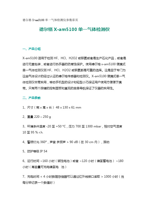
德尔格X-am5100单一气体检测仪参数彩页德尔格X-am5100单一气体检测仪一、产品介绍X-am5100适用于检测HF、HCl、H2O2 或联氨或者是生产石化产品,或者是进行无菌包装,或者进行热手器的防腐蚀保护。
使用德尔格x-am5100便携式单一气体检测仪测HF、HCl、H2O2 或联氨都是可靠的选择。
这是益于专门为这些气体设计的经过认证的德尔格传感器和检测仪。
X-am5100便携式单一气体检测仪非常实用,移动手机型的设计和轻型小巧保证用户使用方便便于携带。
只有两个按键的控制面板和直观的菜单导航保证了仪器的实用性。
二、产品参数1、尺寸(宽 x 高 x 长) 48 x 130 x 61 mm2、重量 220 – 250 g3、环境条件温度 -20 至 +50 °C,压力 700 至 1300 mbar,相对空气湿度10 至 95 % r.h.4、警报灯光 360°,声音多频声 > 90 dB(在 30 cm 内),振动5、防护等级IP 546、运行时间 ~160 小时(碱性电池)或者 ~120 小时(镍氢蓄电池) ~180 小时(高容量可充电镍氢电池)7、充电时间 < 4 小时数据存储器可以通过红外线接口读取 > 1000 小时(当每分钟记录一个数值时)8、认证 ATEX I M1 Ex ia I Ma II 1G Ex ia IIC T4/T3 Ga -20 °C ≤ Ta ≤+55/40 °C IECEx Ex ia I Ma Ex ia IIC T4/T3 Ga -20 °C ≤ Ta ≤ +55/40 °CCE 标识电磁兼容性指令 2004/108/EC 防爆指令 94/9/仪器外部有一层橡胶使得仪器更坚固耐用且防护等*为IP65。
背面配有的腰带夹可将仪器别在使用者的工作服上。
聚创环保为您提供全面的技术支持和完善的售后服务!。
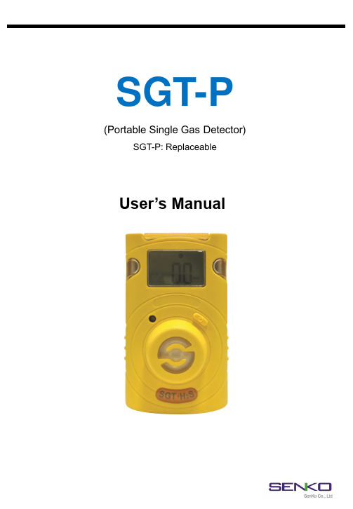
SGT-P 可替换型气体传感器手持检测仪用户手册说明书
SGT-P (Portable Single Gas Detector) SGT-P: ReplaceableUser’s ManualProduct OverviewSGT-P is a portable single gas detector designed to detect the presence of oxygen, toxic and combustible gases in the ambient environment. SGT-P is the replaceable type of a gas sensor and battery. When activated, SGT-P continuously monitors ambient air for the presence of a specific gas and alerts the user to potentially unsafe exposure with LED, vibrating, and audible alarms in the event that gas concentration exceeds alarm set points. And the alarm set point, calibration range, and display configuration can be changed via SENKO-IR Link (Optional). WARNINGAny unauthorized attempt to repair or modify the product,or any other cause of damage beyond the range of the intended use,including damage by fire,lightening,or other hazard,voids liability of the manufacturer.Activate this product only if sensor,visual,detection,and audible cover are clear from contaminants such as dirt and debris that could block the area where gas is to be detected.Do not clean and rub the LCD screen of the products with a dry cloth or hands in hazardous environment to prevent the static electricity.Perform cleaning and maintenance of the products in fresh air that is free of hazardous gasesTest the response of a sensor regularly by the gas concentration exceeding alarm set point.Test LED,audio and vibration manually.Gas concentration measurements by the sensor can vary based on the environment(temperature, pressure and humidity).Therefore,calibration of SGT-P should be performed in the same(or similar) environment of the device’s actual use.If the temperature changes sharply during use of the device(e.g.,indoors vs outdoors),the value of the measured gas concentration can suddenly change.Please use the SGT-P after the gas concentration value has stabilized.Severe vibration or shock to the device may cause a sudden reading change.Please use SGT-P after the value of gas concentration has stabilized.Excessive shock to SGT-P can cause the device and/or sensor to malfunction.All alarm value is set based on the alarm standard that is required by international standard.Therefore,alarm values should be changed only under the responsibility and approval of the administration of the work site where the instrument is used.Use IR communications in the safety zone which is free of hazardous gases.Replace the battery and sensor in clean environment,which is free of hazardous gas.CAUTIONBefore operating this device,please read the manual carefully.This device is not a measurement device,but a gas detector.If calibration and self-test fails continuously,please do not use the device.For the O2detector,perform calibration every30days in the fresh air environment.Before use,please check the activation date,and if the activation date is past,please do not use the device.Clean detectors with a soft cloth and do not use chemical substances for cleaning.To maintain24months life time,avoid the below activities except the necessary cases to check events(Max/Min),lifetime/concentration,and alarm set points.Otherwise,the frequent use of the button will deplete the battery lifetime less than24months.1.Push the button frequently without valid reasons.2.Frequent alarm operation or alarms are remained for a long time.*Normal Alarm Use:1timeand2minutes per day.3.Connect with the SGT-P IR Link frequently except the bump testing.View a serial number on the label at the back side of the device.(ex,20170101)1.The serial number indicates below.ex) SG 01 01 0012017(Year) 01(Months)01(Day)001(Manufacture Order)Table Contents1. Product Overview …………………………………………………..................…2. Activation & Deactivation …………………………………………..................…3. Mode 1) Measuring Mode 2) Display Mode 3) Alarm Activation & Setting Alarm Set Points4. Event Log5. Calibration 1) Fresh Air Calibration 2) Standard Gas Calibration 3) Return to Measuring mode6. Self Test &Bump Test7. Specification 9. Certification …………………………………………………..................………………………………………………...................………………………………………………...................…….………..….……....………………………………………………………..................……………………………………………………..................………………….……………………….............………………….……………………….............………………….……………………….............……………………………………………………..................………………………………………………...................……………………………………………………..................…456666688991011128. Sensor & Battery Replacement …………………………………...................…1110. Warranty (13)1. Product OverviewIR PortLCD displayAlarm LEDBuzzerButtonGas sensorGas TypeLCD Display SymbolsAlarm condition Remaining Month(Month)Low Alarm Display Remaining DayHigh Alarm Display Remaining Time(Hour)Stabilization Success Max Peak ValueStabilization Failure Min Peak ValueFresh Air Calibration Measurement UnitStandard Gas Calibration Remaining Battery Life2. Activation & Deactivation<CAUTION>Before use, check the manufacturing date on the box. Please do not open if it isover the shelf life below.Shelf LifeSGT-P-Oxygen: 6 months from the manufacturing dateSGT-P-Toxic: 6 months from the manufacturing dateIn a safe environment, when pressing and holding the button for 3 seconds, gas type and firmware version (ex. v2.2) will be displayed. For 10 seconds countdown, the device will be stabilized. After stabilization is completed, “V” icon will appear on the display screen and the device will move to Measuring mode.OFFIn the event that stabilization of the device fails, will appear on the display and Measuring mode will not be entered. In this case, contact authorized reseller or SENKO service center at 82-31-492-0445 for repair / return information.To deactivate the device, pleas press and hold the button for three seconds.<CAUTION>Always ensure that the device makes the proper detection response to the pertinent gas. Verify that debris that could interfere with the detection of gas are not blocking the area where gas is to be detected.3. Mode3.1. Measuring mode•When activated, in Measuring mode, gas concentration will appear onthe screen.•Oxygen concentration is displayed in percent by volume (%Vol) andtoxic concentration is displayed in parts per million. (PPM)3.2. Display modeIn Measuring Mode, by pressing button for one second, the following ICONs will appear in order.Min (only for oxygen) -> Max -> clr-> 1st alarm set point -> 2nd alarm set point -> Firmware version -> Remaining Calibration Day -> Calibration Concentration. At the last step, if you press button or do not push any button for a second, the device will return to Measuring Mode.3.3. Alarm Activation & Setting Alarm set pointsWhen the gas concentration exceeds alarm set points, or will be displayed and the device will vibrate, flash (LED), and beep. To remove alarms, move to a clean air location. and then a gas concentration will decrease, and alarm will stop.To set the alarm setpoints, please follow the steps below.-Press the button until the above alarm setpoint is displayed.-Press and hold the button for three seconds and the first digit of alarm setpoint starts to blink.-To increase the value, press the button for one second .-To save the alarm setpoints, press the button for 3 seconds.*Ensure that the second alarm set point must be greater than first alarm setpoint.*Ensure Standard Factory alarm set points vary depending on countries, states, and companies.Before changing alarm setpoints, please ensure the alarm set points are in compliance with yourlocal guidelines.4. Event LogLast 30 events are stored on a device. Once more than 30 events are stored, the log events are removed automatically in the order starting at Event 1. And, the stored log events data can betransferred to SENKO-IR LINK. Each alarm event records followings:-Types of alarms (1st or 2nd) / Alarm concentration in ppm or % / Peak concentration5. CalibrationWhen pressing and holding the button for 5 seconds in the calibration mode( ), icon and ‘CAL’ mark will appear on the LCD.And, press the button to initiate calibration for three seconds. When calibration begins, a countdown (starting at 10) will appear on the screen. <CAUTION > Initial calibration is performed on all devices prior to shipment. Once received, calibration should be performed monthly (or quarterly) depending on frequency of use.5.1. Fresh Air Calibration Fresh Air Calibration Standard Gas CalibrationOnce completed, icon will appear on the LCD.If calibration fails, icon will appear on the display. If this continues, please contact the sales representative or SENKO service center.<CAUTION > Calibration should be performed in a fresh-air environment that is free for any influence of other gases (since calibration is assumed to be performed in an environment with 20.9% of Oxygen). It is also recommended that calibration should be performed in a space that is not confined.5.2. Remaining Calibration DayIf you set the calibration interval via IR LINK, the remaining day will bedisplayed. To check the remaining day, press the button until the above imageis displayed.Initial SettingThe default day will be 180daysWhen pressing and holding the button for 5 seconds in the calibration mode , icon and ‘CAL’ mark will appear, and when pressing button once again, icon will appear. And then, press and hold the button for three second to initiate calibration. When calibration begins, a countdown (60 seconds or more depending on sensor types) will appear on the screen.5.2. Standard Gas CalibrationOnce completed, icon will appear several seconds on the display. Then, the device will return to Measuring mode.Once calibration fails, icon will appear on the display. If this continues, please contact the sales representatives or SENKO service center.In the standard calibration mode , by pressing the button for a second, the fresh air calibration, standard calibration, and ESC will appear on the display consecutively. In the ESC mode, press the button for 3 seconds, the device will be get out of the calibration mode. And press the button onetime, it will return Measuring mode.5.3. Return to Measuring Mode.Calibration concentration.Gas O2CO H2S H2SO2Cl2NH3NO2Concentration0.0%Vol(N2:99.9%Vol)100 ppm50 ppm500 ppm10ppm10ppm100ppm10pm6. Self Test & Bump Test6.1. Self TestThe default of Self-Test is N/A, and the interval is 8hr~20hr, or N/A. To initiate the self-test, please set the self-test interval via the IR link. After the setting interval is activated, STS message will flash.(The message will flash until users perform the Self-test.) Once you press the button, it will testbuzzer, LED, Vibration, LCD, 1ST alarm, and 2ND alarm. After the test is completed, END message with icon will be displayed. (Users are required to check the test processes manually.)6.2. Bump TestThe interval of Bump-test is 1~365days, and the default is N/A. To initiate the bump test, set the bump test interval. Once the bump test time reaches, bts message will flash. Once you press and hold the button for 3 seconds, the tst message will be displayed for 45 seconds (To cancel, press the button for one second). Within the 45 seconds, apply a test gas (If no gases are applied, the btsmessage will flash again). After the selected gas is applied, if the test is successful, SUC message with will be displayed after 30 seconds. And then, remove the calibration cap and gas tube. If the test fails, FA message with will be displayed and bts message will be flashing until the test is successful.7. Sensor & Battery Replacement<CAUTION>1.It is absolutely prohibited to replace battery at potential explosion or dangerous regions.Replace the battery in a clean environment, which has no hazardous gases.2.Replacement of components can invalidate the intrinsic safety function. Replacing thesensor and battery should be performed by authorized sellers, agents, distributors, ormanagers.3.The sensors published by SENKO should be used for replacement.Product: Tekcell(SB-AA02 3.6V) / Brand: Vitzrocell, Co.Ltd4.Disassembly should be necessary only for sensors & battery replacement. After the sensorreplacement, the span gas calibration should be done.5. Before disassembling, please turn off the power and remove screws.7.1. Sensor Replacement1.Deactivate the detector2.Remove the 6 screws on the back case.3.Remove the 2 screws on the PCB board.4.After removing the battery, replace with the new sensor matching with the gas type. For instance,If you have the SGT-P CO, the CO sensor should be used for the replacement.5. Assemble the detector.6. After assembling, perform the fresh air calibration and standard calibration with theconcentration in this manual.6.Have the sensor stabilized for 5 minutes before use.7.2. Battery Replacement1.Deactivate the detector2.Remove the 6 screws on the back case.3.Replace with the new battery.4.Assemble the detector.5.After assembling, perform the fresh and standard calibration.6.Before use, have the sensor stabilized for 5 minutes.Model SGT-PMeasure Gas O2CO H2S H2SO2Cl2NH3NO2 Range 0~30%Vol0~500ppm0~100ppm0~1000ppm0~50ppm0~20ppm0~100ppm0~20ppm Sensor Type ElectrochemicalMeasurement Diffusion typeDisplay LCD displayAudible 90dB at 10cmWarningLampRed Flashing LEDs (Light-Emitting Diode) Vibration Vibration AlarmBattery Manufacture: Vitzrocell/ P/N: SB-AA02(P) / System: Lithium Primary Battery Nominal voltage: 3.6V / Nominal capacity: 1.2AhTemperature & Humidity -40℃~ +50℃(for Toxic) / -35℃~ +50℃(for O2) 5% ~ 95% RH (non-condensing)Case Rubber EnclosureAccessories Calibration Cap, Manual, Test Report Option External Sampling Pump (SP-Pump101), SENKO-IR Link, Docking StationSize & WeightSize: 54mm(W) x 91mm(H) x 32mm(D)/ Weight: 93g(Toxic), 104g(O2) (Battery, clip included)OperatingLife24 months, based on 2 minutes of alarm per dayEvent Log Recent 30 alarmsApproval Ex ia IIC T4 Ga/ IP67 (Korea Ex, IECEx, ATEX, CSA & UL, INMETRO12Intrinsic Safety:The detector is in conformity of the following standardsIECEx: Ex ia IIC T4GaIECEx KTL 19.0019XExplosion Protected Protection Concept Gas GroupTemperature Classification Equipment Protection levelATEX: 2198II 1 G Ex ia IIC T4 Ga IP67KRH 19 ATEX 1022X Directive 2014/34/EUKCS: Ex ia IIC T4KTL 19-KA2BO-0491XCompliance: Electromagnetic Compatibility Directive 2014/30/EUStandards:The electrical apparatus and any acceptable variations to it specified in the schedule of this certificate and the identified documents, was found to comply with the following standards:•IEC 60079-0: 2011 Ed. 6•IEC 60079-11: 2011 Ed 6•UL 61010-1, Ed. 3•UL 913, Ed. 8•UL 60079-0, Ed. 6•UL 60079-11, Ed. 6•C22.2 No. 60079-0:2015•C22.2 No. 60079-11:2014•C22.2 No. 61010-1-12:2012•EN 60079-0: 2012+A11:2013 •EN 60079-11: 2012Manufacturing Approval:The detector manufacturer is certified compliant with ISO 9001:2000 provisions12①②③①②③④⑤④⑤Limited WarrantySENKO warrants this product to be free of defects in workmanship and materials-under normal use and service for two years from the date of purchase from the manufacturer or from the product’s authorized reseller.The manufacturer is not liable (under this warranty) if its testing and examination disclose that the alleged defect in the product does not exist or was caused by the purchaser’s (or any third party’s) misuse, neglect, or improper installation, testing, or calibrations. Any unauthorized attempt to repair or modify the product, or any other cause of damage beyond the range of the intended use, including damage by fire, lightening, water damage or other hazard, voids liability of the manufacturer.In the event that a product should fail to perform up to manufacturer specifications during the applicable warranty period, please contact the product’s authorized reseller or SENKO service center at 82-31-492-0445 to repair/return information.73, Oesammi-ro15 beon-gil, Osan-si, Gyeonggi-do, 18111, South KoreaTel : 82-31-492-0445 Fax : 82-31-492-0446Email:**************.krWeb:www.senko.co.kr13。
国家电网公司变电运维管理规定试行第1分册油浸式变压器电抗器运维细则共17页.doc
国家电网公司变电运维管理规定(试行)第1分册油浸式变压器(电抗器)运维细则国家电网公司二〇一七年三月目录前言 (II)1 运行规定 (1)1.1 一般规定 (1)1.2 运行温度要求 (2)1.3 负载状态的分类及运行规定 (2)1.4 运行电压要求 (3)1.5 并列运行的基本条件 (3)1.6 紧急申请停运规定 (3)2 巡视及操作 (4)2.1 巡视 (4)2.2 操作 (6)3 维护 (7)3.1 吸湿器维护 (7)3.2 冷却系统维护 (7)3.3 变压器事故油池维护 (7)3.4 瓦斯继电器放气 (7)3.5 变压器铁心、夹件接地电流测试 (7)3.6 红外检测 (7)3.7 在线监测装置载气更换 (8)4 典型故障和异常处理 (8)4.1 变压器本体主保护动作 (8)4.2 变压器有载调压重瓦斯动作 (8)4.3 变压器后备保护动作 (9)4.4 变压器着火 (10)4.5 变压器套管炸裂 (10)4.6 压力释放阀动作 (11)4.7 变压器轻瓦斯动作 (11)4.8 声响异常的 (12)4.9 强油风冷变压器冷却器全停 (12)4.10 油温异常升高 (13)4.11 油位异常 (13)4.12 套管渗漏、油位异常和末屏放电 (13)4.13 油色谱在线监测装置告警 (14)前言为进一步提升公司变电运检管理水平,实现变电管理全公司、全过程、全方位标准化,国网运检部组织26家省公司及中国电科院全面总结公司系统多年来变电设备运维检修管理经验,对现行各项管理规定进行提炼、整合、优化和标准化,以各环节工作和专业分工为对象,编制了国家电网公司变电验收、运维、检测、评价、检修管理规定和反事故措施(以下简称“五通一措”)。
经反复征求意见,于2017年3月正式发布,用于替代国网总部及省、市公司原有相关变电运检管理规定,适用于公司系统各级单位。
本细则是依据《国家电网公司变电运维管理规定(试行)》编制的第1分册《油浸式变压器(电抗器)运维细则》,适用于35kV及以上变电站油浸式变压器(电抗器)。
西安瑞斯特 PT2C-1564 气体检测仪 GD-70D 系列 GD-70D GD-70D-NT G
PT2C-1564气体检测仪GD-70D系列GD-70DGD-70D-NTGD-70D-EAGD-70D-DVGD-70D-LN使用说明书目录1 产品概要1-1. 前言・・・・・・・・・・・・・・・・・・・・・・・・・・・・・・・・・・・・ 31-2. 使用目的・・・・・・・・・・・・・・・・・・・・・・・・・・・・・・・・・・ 31-3. 危险、警告、注意、注记的定义・・・・・・・・・・・・・・・・・・・・・・・・ 31-4. CE/UKCA标志规格的确认方法・・・・・・・・・・・・・・・・・・・・・・・・・ 32 安全重要事项2-1. 危险事项・・・・・・・・・・・・・・・・・・・・・・・・・・・・・・・・・・ 42-2. 警告事项・・・・・・・・・・・・・・・・・・・・・・・・・・・・・・・・・・ 42-3. 注意事项・・・・・・・・・・・・・・・・・・・・・・・・・・・・・・・・・・ 53 产品组成3-1. 主机及标准附件・・・・・・・・・・・・・・・・・・・・・・・・・・・・・・・ 63-2. 外形图・・・・・・・・・・・・・・・・・・・・・・・・・・・・・・・・・・・73-3. 各部名称与作用・・・・・・・・・・・・・・・・・・・・・・・・・・・・・・・83-4. 框图・・・・・・・・・・・・・・・・・・・・・・・・・・・・・・・・・・・・164 使用方法4-1. 使用时・・・・・・・・・・・・・・・・・・・・・・・・・・・・・・・・・・・18 4-2. 关于安装场所的注意事项・・・・・・・・・・・・・・・・・・・・・・・・・・・18 4-3. 系统设计上的注意事项・・・・・・・・・・・・・・・・・・・・・・・・・・・・19 4-4. 安装方法・・・・・・・・・・・・・・・・・・・・・・・・・・・・・・・・・・21 4-5. 配线方法・・・・・・・・・・・・・・・・・・・・・・・・・・・・・・・・・・24 4-6. 配管方法・・・・・・・・・・・・・・・・・・・・・・・・・・・・・・・・・・345 操作方法5-1. 启动准备・・・・・・・・・・・・・・・・・・・・・・・・・・・・・・・・・・35 5-2. 基本操作流程・・・・・・・・・・・・・・・・・・・・・・・・・・・・・・・・35 5-3. 启动方法・・・・・・・・・・・・・・・・・・・・・・・・・・・・・・・・・・36 5-4. 关于各种模式・・・・・・・・・・・・・・・・・・・・・・・・・・・・・・・・37 5-5. 检测模式・・・・・・・・・・・・・・・・・・・・・・・・・・・・・・・・・・38 5-6. 警报测试模式・・・・・・・・・・・・・・・・・・・・・・・・・・・・・・・・38 5-7. 用户模式・・・・・・・・・・・・・・・・・・・・・・・・・・・・・・・・・・39 5-8. 结束方法・・・・・・・・・・・・・・・・・・・・・・・・・・・・・・・・・・436 各种动作和功能6-1. 气体警报操作・・・・・・・・・・・・・・・・・・・・・・・・・・・・・・・・44 6-2. 故障警报操作・・・・・・・・・・・・・・・・・・・・・・・・・・・・・・・・48 6-3. 外部输出操作・・・・・・・・・・・・・・・・・・・・・・・・・・・・・・・・49 6-4. 关于各种功能・・・・・・・・・・・・・・・・・・・・・・・・・・・・・・・・52 6-5. 关于LONWORKS(LN规格) ・・・・・・・・・・・・・・・・・・・・・・・・・・・547 保养检查7-1. 检查频率和检查项目・・・・・・・・・・・・・・・・・・・・・・・・・・・・・57 7-2. 定期检查模式・・・・・・・・・・・・・・・・・・・・・・・・・・・・・・・・58 7-3. 气体校正方法・・・・・・・・・・・・・・・・・・・・・・・・・・・・・・・・73 7-4. 其他调整和清扫方法・・・・・・・・・・・・・・・・・・・・・・・・・・・・・75 7-5. 各部件的更换方法・・・・・・・・・・・・・・・・・・・・・・・・・・・・・・768 关于储存、移机和报废8-1. 储存或长期不使用时的处理・・・・・・・・・・・・・・・・・・・・・・・・・・78 8-2. 移机或者重新使用时的处理・・・・・・・・・・・・・・・・・・・・・・・・・・78 8-3. 产品的报废・・・・・・・・・・・・・・・・・・・・・・・・・・・・・・・・・789 故障排除・・・・・・・・・・・・・・・・・・・・・・・・・・・・・・・・・・8010 产品规格10-1.规格一览・・・・・・・・・・・・・・・・・・・・・・・・・・・・・・・・・・83 10-2.附件一览・・・・・・・・・・・・・・・・・・・・・・・・・・・・・・・・・・86 10-3.检测原理・・・・・・・・・・・・・・・・・・・・・・・・・・・・・・・・・・8711 术语的定义・・・・・・・・・・・・・・・・・・・・・・・・・・・・・・・・・981.产品概要1-1.前言感谢您购买GD-70D 系列气体检测仪。
气体安全检测仪器培训教材PPT课件

经调查发现,事故原因是设备 老化、维护不当导致气体管道 破裂。
消防、环保等部门迅速赶到现 场,使用气体安全检测仪器检 测泄漏气体的种类和浓度,采 取措施控制泄漏源,并对泄漏 气体进行处置。
事故暴露出企业对设备维护管 理不到位、安全意识薄弱等问 题。应加强设备巡检、完善安 全管理制度、提高员工安全意 识等措施,预防类似事故再次 发生。
供数据支持。
水质监测
在水质监测中,气体安全检测仪器 用于检测水体中的有害气体和氧气 含量,确保水质安全。
土壤监测
在土壤监测中,气体安全检测仪器 用于检测土壤中的有害气体和挥发 性有机物,评估土壤污染状况。
公共安全中的应用场景
消防救援
在消防救援中,气体安全检测仪器用于快速检测火灾现场的有毒 有害气体和氧气浓度,为救援提供科学依据。
05
气体安全检测仪器操作规范与注意事
项
操作规范
根据检测需求选择合适的检 测模式和量程,避免超量程
使用。
仪器使用前应检查电源、气 源是否正常,确保仪器处于
良好工作状态。
01
02
03
严格按照仪器说明书进行操 作,遵循操作步骤,避免误
操作。
检测过程中应保持仪器稳定, 避免剧烈震动或撞击。
04
05
检测结束后,及时关闭仪器, 断开电源,整理存放。
注意事项
01
仪器应存放在干燥、无 尘、无腐蚀的环境中, 避免阳光直射和高温。
02
定期对仪器进行校准和 维护,确保仪器准确性 和可靠性。
03
对于有毒、有害、易燃 易爆气体,应选择经过 认证的合格仪器,并注 意个人防护。
04
仪器出现异常或故障时, 应及时停止使用,联系 专业人员进行维修。
(情绪管理)GRT—、气体继电器压力释放阀自动测试仪
安全指南尊敬的用户,感谢您选用我们的产品,为便于仪器能正常使用,请先阅读下列说明:1.请遵守仪器和说明书上标示各种警告及说明事项;2.清洁仪器时,请先关闭电源,拔下电源插头;3.为避免损伤仪器底部,请勿将本产品放置于不平物和表面上;4.请使用说明书指定的电源为仪器供电;5.切勿将任何物体插入仪器内。
机内有高压、变压器油,避免导致电击、短路或火灾;6.请在看懂本说明书后才使用仪器;7.请妥善保存本说明书,以便随时查阅;注意:发生下列情形时,请关闭电源和拔下电源插头,并与维修人员联系,我们将及时地帮助您解决问题。
1.电源线损坏或磨损;2.仪器遭受雨淋(或其它液体);3.虽按正确方法使用,但仪器仍无法正常工作;4.曾进行不正确的调整;5.本产品跌落或损坏;6.本产品性能无法完全发挥效能。
RLC-8(QYG)气体继电器压力释放阀自动测试仪主要特点RLC-8QYG型气体继电器压力释放阀自动测试仪是在RLC-7QYG2型半自动校验台的基础上改进的高科技专利新产品,其主要特点是:1.流速测量模拟变压器内部故障情况,采用压差法测脉冲流速的原理是经原能源部电力司组织全国专家技术评审认为:测试原理先进,测量离散率小,误差符合要求,携带方便、适于现场使用,是全国急需的试验设备,很有推广使用价值。
2.采用东北、华中、云南的综合计量基准,可在全国范围内适用。
新设计有两种误差修正装置,使测量精度符合国内外标准校验台校验要求。
3.功能更多、应用范围更广。
除具有直接测试QJ-25、QJ-50、QJ-80、QI-50W、QJ-80W型继电器流速、容积、密封等检验项目外,还可满足变压器YSF-25、50、80、130型压力释放阀进行开启、关闭压力试验。
4.本测试仪自动化程度高。
采用微机测控、数码显示,操作试验时除人工配合回油外,实现了测量、参数调整、控制操作、记录打印自动化。
5.本测试仪技术性能完全可代替固定式油泵法校验台使用,并具有体积小,便于携带、满足现场试验需要,节约设备和试验室大量投资等优点。
- 1、下载文档前请自行甄别文档内容的完整性,平台不提供额外的编辑、内容补充、找答案等附加服务。
- 2、"仅部分预览"的文档,不可在线预览部分如存在完整性等问题,可反馈申请退款(可完整预览的文档不适用该条件!)。
- 3、如文档侵犯您的权益,请联系客服反馈,我们会尽快为您处理(人工客服工作时间:9:00-18:30)。
(情绪管理)GRT—、气体继电器压力释放阀自动测试仪安全指南尊敬的用户,感谢您选用我们的产品,为便于仪器能正常使用,请先阅读下列说明:1.请遵守仪器和说明书上标示各种警告及说明事项;2.清洁仪器时,请先关闭电源,拔下电源插头;3.为避免损伤仪器底部,请勿将本产品放置于不平物和表面上;4.请使用说明书指定的电源为仪器供电;5.切勿将任何物体插入仪器内。
机内有高压、变压器油,避免导致电击、短路或火灾;6.请于见懂本说明书后才使用仪器;7.请妥善保存本说明书,以便随时查阅;注意:发生下列情形时,请关闭电源和拔下电源插头,且和维修人员联系,我们将及时地帮助您解决问题。
1.电源线损坏或磨损;2.仪器遭受雨淋(或其它液体);3.虽按正确方法使用,但仪器仍无法正常工作;4.曾进行不正确的调整;5.本产品跌落或损坏;6.本产品性能无法完全发挥效能。
RLC-8(QYG)气体继电器压力释放阀自动测试仪主要特点RLC-8QYG型气体继电器压力释放阀自动测试仪是于RLC-7QYG2型半自动校验台的基础上改进的高科技专利新产品,其主要特点是:1.流速测量模拟变压器内部故障情况,采用压差法测脉冲流速的原理是经原能源部电力司组织全国专家技术评审认为:测试原理先进,测量离散率小,误差符合要求,携带方便、适于现场使用,是全国急需的试验设备,很有推广使用价值。
2.采用东北、华中、云南的综合计量基准,可于全国范围内适用。
新设计有俩种误差修正装置,使测量精度符合国内外标准校验台校验要求。
3.功能更多、应用范围更广。
除具有直接测试QJ-25、QJ-50、QJ-80、QI-50W、QJ-80W型继电器流速、容积、密封等检验项目外,仍可满足变压器YSF-25、50、80、130型压力释放阀进行开启、关闭压力试验。
4.本测试仪自动化程度高。
采用微机测控、数码显示,操作试验时除人工配合回油外,实现了测量、参数调整、控制操作、记录打印自动化。
5.本测试仪技术性能完全可代替固定式油泵法校验台使用,且具有体积小,便于携带、满足现场试验需要,节约设备和试验室大量投资等优点。
6.RLC-8QYG测试仪配有QJ-25、50、80流速测量尺共3把,可分别直接测试相同型号气体继电器动作流速,且和测试仪进行定期校核,是理想的量值传递工具。
7.本测试仪实现了气体继电器流速、容积、密封试验和压力释放阀开启、关闭压力等检验项目,全部自动测试且打印记录。
结构原理如附图壹、二、三、四所示:RLC-8QYG型自动测试仪由气体继电器校验台、释放阀校验台和微机测控箱、微型电动空压机四部分组成。
由气体继电器校验台和微机测控箱、空压机组成气体继电器自动测试仪(图壹);由压力释放阀校验台和微机测控箱、空压机组成压力释放阀自动测试仪(图二)。
气体继电器校验台底部设有油盆(图中未画出),可调支架20装于油盆内,支架四角有调整水平的调节螺钉,由拉杆紧固件18将带水平仪7、压力油筒2的组件和带快速阀11的回油筒14组件通过被试继电器8组成整体,通过拉杆中部的轴承将组装好的本体支承于轴承座上,拉杆18上装有双向定位板21的孔和轴承座上定位销19构成90°的自动定位,由于俩侧重量相近,试验人员可轻松地将校验台旋转至水平或垂直位置。
压力油筒2顶部有进气阀3可通过微型空压机(图中示画出)的软管24连接,压力油筒顶部装有压力传感器5和电磁排气阀6,通过带插头的屏蔽电缆22和微机测控箱1后板的传感器电缆接口39相接,水平仪7装于带法兰盘的压力油筒2的出口处;回油筒14和带法兰盘的电磁快速阀11通过螺纹连接成组件。
电磁快速阀11设有油位开关17,法兰盘靠外侧装有软管9和换气阀10,试验时将软管和被试继电器顶盖上的气塞连接;法兰盘靠外侧装有放油阀16,可将继电器的油通过软管和回油筒14底部的容积计量装置15连接。
通过电缆和电磁快速阀上的安装的测量插口12连接,再由电缆23和测控箱后板上的信号插座45连接。
微机测控箱1后板布置见图2;布置有传感器连接插口39、测量信号电缆插口45、轴流风机40、电源开关41、保险器42和电源插座43,微型电动空压机电源插座44。
微机测控箱1内部元件布置采用分类重复屏蔽措施,有效地减少信号干扰。
主控、驱动、电源三块板平行组装插入箱内,通过插口接头和箱体其它元件连接以方便检验维修。
采用四位数码显示器,以满足流速、容积、压力显示要求。
微机测控箱1的面板布置见图壹:模式开关33和流速指示灯34、容积指示35、压力指示灯36、信号指示灯37、调零电阻38装于面板右上角。
微型打印机31装于左下角,左上角布置四位数码流速、容积、压力显示器32,右下侧布置功能曲线开关29,流速、压力整定开关26,中层分别布置试验开关30、容积试验开关28、排气阀开关27、空压机进气阀开关25;功能曲线旋钮有11档,可选择4种不同型号的继电器流速试验,1~4档分别为QJ-25、QJ-50、QJ-80型流速试验,5档为“P1”压力试验,调零、6档为“V”容积试验,第7档为“P2”档释放阀压力调零,第8~11档分别为YSF/25、YSF/50、/80、/130型释放阀开启压力试验;流速压力整定旋转26有11档,外圈刻度线1~11档分别为0.5~1.5m/s流速整定值;内圈刻度线3~9档分别为15、25、35、55、70、85、100kpa压力整定值预置参数。
如图壹、二所示:由释放阀校验台和微机测控箱组成压力释放阀校验仪(空压机图中未画出),试验介质为空气。
校验台由储气筒46通过三通管和电磁阀连接,储气筒壹侧装有压力传感器5,后侧装有排气阀3(图中未画出),另壹侧装有接线柱53和插口54且通过电缆23和释放阀插口45连接。
设计有4种规格的密封盘,Ф130为47、Ф80为48、Ф50为49、Ф25为50,试验时选择和压力释放阀52相同型号的密封盘组装于壹起,最后装上信号支架51,本校验仪可满足YSF-/25、-/50、-/80、-/130型压力释放阀进行开启/关闭压力试验。
为了校验仪经常处于准确可靠状态,方便定期检验和量值传递,RLC-8QYG型校验仪随机配有RLC-QJ-25、QJ-50、QJ-80流速尺各壹把,出厂时用相同型号的继电器做校验仪和流速尺对比试验,用流速尺测量时,随机配有壹个9V电池的声光信号装置(图中未示出)。
技术参数RLC-冉式校验仪代号。
R代表专利发明人冉式,L代表“流速”,C代表“尺”,因第壹代设计产品为“流速测量尺”、RLC代表“冉式流速尺”,以后产品不断更新换代均沿用“RLC”。
8QYG型:8代表第8次设计序号、Q代表气体继电器、Y 代表压力释放阀、8QYG代表气体继电器、压力释放阀自动测试仪。
1.气体继电器:1.1流速试验:0.5~1.6m/s,最小分辨率0.02m/s精度0.5级,绝对误差值≦0.04m/s1.2容积试验:250~300ml,最小分辨率5ml,精度0.5级最大误差≤5%;1.3密封试验:0~150Kpa,最小分辨率1Kpa,精度1.5级,时间20min;2.YSF-4型压力释放阀:2.1Φ25、Φ50有口径的开启压力/关闭压力为15/8;25/13.3;35/19;55/29.5Kpa2.2Φ80、Φ130有口径的开启压力/关闭压力为35/19;55/29.5;70/37.5;85/45.5Kpa;2.3最小分辨率2Kpa,精度0.5级,用于测试压力释放阀开启/关闭压力。
3.试验介质:3.1气体继电器试验介质为25#变压器油;3.2压力释放阀试验介质为空气。
4.RLC-QJ25、QJ-50、QJ-80型流速尺4.1RLC-QJ80型流速尺流速量程:0.6~1.6m/s,感量0.01m/s,误差≦0.04m/s。
流速尺身和大、小法码均为黄铜制作。
当流速整定值为0.6~1.0m/s,用小法码读取尺身上刻度线左边缘刻度值;当流速整定值为1.05~1.60m/s时,用大法码读取下刻度线左边缘刻度值。
4.2RLC-QJ50型流速尺流速量程:0.55~1.6m/s,感量0.01m/s,误差≦0.04m/s,流速尺身和大、小法码为黄铜制作,当≦1.0m/s用小法码读取上刻度线,当>1.0m/s用大法码读下刻度线。
4.3RLC-QJ25型流速尺流速量程:0.9~1.4m/s,感量0.01m/s,相对误差≦5%,尺身为铝质、只有壹个法码为黄铜制作,只有壹条刻度线。
5.微机测控箱电源:1Φ220V150W6.电动微型空压机:1Φ220V120W7.仪器箱:7.1气体继电器校验台(木质)外形尺寸:长×宽×高55×30×46cm重35kg7.2压力释放阀校验台(铝合金箱)外形尺寸:长×宽×高48×37×36cm重20kg7.3微型测控箱(铝合金箱)外形尺寸:长×宽×高42×40×25cm重15kg7.4电动微型空压机(外购件)使用方法1.气体继电器试验:1.1检验前准备工作:将各部件从仪器箱中取出。
将校验台油盆置于试验桌上,可调支架20放于油盆内,四角有调节螺钉将支架初调平稳,支架安放的方向如图壹所示。
将压力油筒2和回油筒14组合件竖立,拆卸连接螺栓,卸下压力筒2和回油筒14;将带有双向定位板21的拉杆18和压力筒2法兰的槽孔配合,将另壹拉杆18和法兰另壹槽孔配合,双手提起拉杆且将其轴放入支架上的轴承座内,且将定位销19插入双向定位板21的孔内,使拉杆固定于垂直位置。
于拉杆上端旋上螺帽、将回油筒组合件法兰插入拉杆上部,放入垫圈、旋上螺帽定位,调整螺帽使上下组件法兰之间的距离应能安装被试继电器,按顺序于压力油筒法兰盘上放上被试继电器8,注意继电器顶盖箭头方向应指向回油筒,装配时以管孔中心和法兰盘边缘为基础,尽量将各部件的孔中心组合于壹条线上,且使继电器和油筒相互平直,最后将俩根拉杆的下螺帽松开,上螺帽对称旋紧。
注意装配时不能用手握住电气元件、快速阀杆等部件,以免损坏或变形。
旋转校验台的方法:右手扶着回油筒,左手拔出定位销19、待校验仪旋转少许即松开左手,继续旋转定位于水平位置。
注意:试验时必须卸下闷盖13;调整可调支架20,使压力油筒2上的水平仪7使校验台处于水平状态。
将继电器抽芯按规程检查应完好,清除绑线、杂物后装复,随机配有垫板壹块,抽芯后将垫板放于外壳顶上,于将继电器芯。
