ADAM4117模块使用手册.pdf
ADAM-4117模块使用手册簿
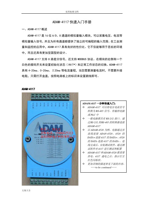
ADAM-4117快速入门手册一、ADAM-4117概述ADAM-4117是16位A/D 、8通道的模拟量输入模块,可以采集电压、电流等模拟量输入信号,并且为所有通道都提供了独立的可编程的输入范围。
在工业测量和监控的应用中,ADAM-4117具有良好的性价比。
它不仅能够用于恶劣的环境中,而且还具有更加坚固型的设计。
ADAM-4117支持8路差分信号,还支持MODBUS 协议。
在模块的右侧有一个白色的拨码开关来设置初始化状态(INIT*)和正常工作状态的切换。
ADAM-4117具有4-20ma 、0-20ma 、±20ma 等电流量程,当您需要测量电流时,不需要外接电阻,只需打开盒盖,按照电路板上的标识来设置跳线即可。
ADAM-4117规格说明AI 模拟量输入●有效分辨率:16位●通道:8路差分,可独立设置量程●高共模电压:200Vdc●通讯协议:ASCII命令,Modbus协议●输入类型:mV,V(支持单双极性),mA●输入量程:0~150mV, 0~500mV, 0~1V, 0~5V, 0~10V, 0~15V,±150 mV, ±500 mV, ±1V, ±5 V, ±10 V, ±15V, 0~20mA,±20 mA, 4~20mA●隔离电压:3000VDC●过压保护:±60V●采样速率:10/100 采样点每秒(通过测试软件设置)●输入内阻:电压20MΩ,电流120Ω●精确度:电压模式:±0.1% or better 电流模式:±0.2% or better●零点漂移:±6μV/℃●跨度漂移:±25 ppm/° C●共模抑制(CMR)@50/60Hz dB min●内置看门狗●内置 TVS/ESD保护●功耗1.2W@24VDC跳线设置:当ADAM-4117测量电流时,需要跳线。
ADAM-4118快速入门手册
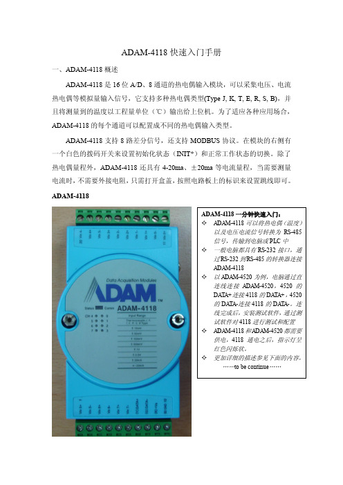
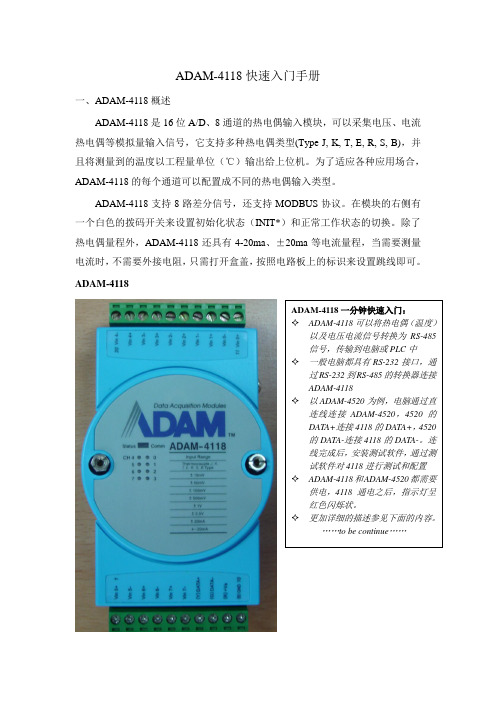
ADAM-4118快速入门手册一、ADAM-4118概述ADAM-4118是16位A/D、8通道的热电偶输入模块,可以采集电压、电流热电偶等模拟量输入信号,它支持多种热电偶类型(Type J, K, T, E, R, S, B),并且将测量到的温度以工程量单位(℃)输出给上位机。
为了适应各种应用场合,ADAM-4118的每个通道可以配置成不同的热电偶输入类型。
ADAM-4118支持8路差分信号,还支持MODBUS协议。
在模块的右侧有一个白色的拨码开关来设置初始化状态(INIT*)和正常工作状态的切换。
除了热电偶量程外,ADAM-4118还具有4-20ma、±20ma等电流量程,当需要测量电流时,不需要外接电阻,只需打开盒盖,按照电路板上的标识来设置跳线即可。
ADAM-4118规格说明AI 模拟量输入● 有效分辨率:16位● 通道:8路差分,可独立设置量程● 高共模电压:200Vdc● 通讯协议:ASCII 命令,Modbus 协议● 输入类型 & 量程范围50mV , ±100mV , ±500mV , ±1V , ±2.5V电流模式 ±20 mA, +4~20 mA● 隔离电压:3000VDC ● 过压保护:±60V● 采样速率:10/100 采样点每秒(通过测试软件设置)● 输入内阻:电压20M Ω,电流120Ω● 精确度:电压模式:±0.1% or better 电流模式& 高速模式:±0.2% or better ● 零点漂移:±6μV /℃● 跨度漂移:±25 ppm/° C● 共模抑制(CMR )@50/60Hz dB min● 内置看门狗● 内置 TVS/ESD 保护● 功耗 1.2W@24VDC跳线设置:ADAM-4118测量电流时需要跳线。
拆开盒盖,可以看到板上有八个跳线,按照下图或电路板标识进行跳线,测电流跳到“I ”端,测量电压保持跳线在“V ”端的出厂设置不变。
ADAM模块设置指南
ADAM模块(4017+,4015)设置指南ADAM4017+和ADAM4015是集成RS485通讯口的数据采集模块,分别用于采集模拟量和PT100温度信号。
在现有产品中,ADAM模块主要用在TX2040,TX1880,TX1400,TX940N等电控系统的变送器箱和左右检测箱中,与PLC主控制模块配合采集各种电流,压力,温度,油位,湿度等信号。
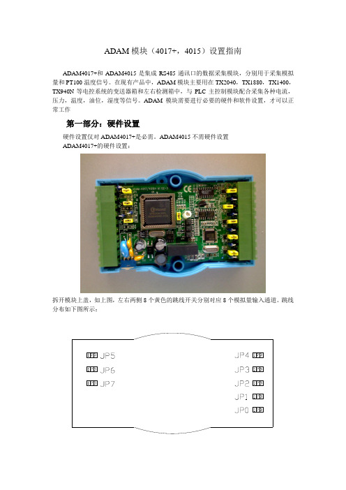
ADAM模块需要进行必要的硬件和软件设置,才可以正常工作第一部分:硬件设置硬件设置仅对ADAM4017+是必需。
ADAM4015不需硬件设置ADAM4017+的硬件设置:拆开模块上盖,如上图,左右两侧8个黄色的跳线开关分别对应8个模拟量输入通道。
跳线分布如下图所示:JP0~JP7分别对应ADAM4017+的0~7通道,用于选择通道输入信号是电压还是电流。
跳线默认位置是短接2和3,对应电压输入。
如果通道输入的是电流信号,则需要将跳线短接1和2.第二部分:软件设置在硬件选择输入信号种类的基础上,还可通过软件设置,选择ADAM4017+和ADAM4015输入信号的测量范围。
要进行软件设置,需要硬件连线和软件安装。
1,硬件连线:2,软件设置:软件设置的工具是:ADAM Utility。
运行界面如下图:(1)设置模块地址:模块初始未设置地址,设置模块地址时,4520须单独连接该模块。
首先在断电状态把模块侧面开关拨至“Init”位置,上电。
点击选择界面中实际使用的COM口,然后点击菜单“TOOLs-〉Search”,软件会自动搜索4520连接的模块并将模块显示在选择的COM口下面。
选中搜索到的模块,出现下面窗口:修改Address:后面的数字,点击Update,即可修改模块地址,修改完后,模块断电,把模块侧面开关拨至“Normal”位置,重新上电,修改地址完成。
(2)设置通道数据:确认侧面开关拨至“Normal”位置,使用上面所述方法搜索到模块,打开该模块设置界面,在“Channel Mode Setting”中选择需要修改的通道“Channel”,改变“Range”,点击Update按钮,完成通道设置。
易控对研华Adam-4017+测试方法
研华Adam-4017+测试方法
模块是接10—30V dc.我在这里测试的时候接的是24V DC
1 研华Adam-4017+的有两种模式,Init和Normal。
Init状态下可以改变模块的协议方式(Modbus协议、研华协议)。
Normal状态下是进行正常通讯的。
如何改变两种协议呢?下面是演示:
首先把模块侧面的拨码开关拨到INIT 一边,表明模块在初始化的状态下,可以修改模块的地址,波特率,协议方式,数据结构等参数。
这些操作时是在研华软件上进行的。
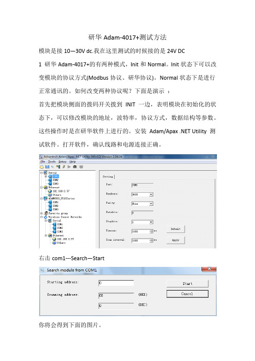
安装Adam/Apax .NET Utility 测试软件。
打开软件,确认线路和电源连接正确。
右击com1---Search—Start
你将会得到下面的图片。
Modbus对应的是标准的Modbus协议,Advantech对应着研华协议如上图所示,有地址、波特率和协议选择的修改。
然后点击---Apply change。
注意:在完成初始化要修改的参数后,把模块断电,然后拨码开关拨到Normal 状态。
模块就可以再正常状态下工作了。
谨记两种协议之间的修改,必须要在Init状态下。
2 打开易控,建立工程。
IO通信---串口---模块---研华--- Adam4017. 这个对应的是研华协议。
以上参数配置请与在研华测试软件上设置的一致。
参数配置好之后,点击运行
在公司测试的时候,设备的协议修改为是Modbus协议,设备地址是3。
您可以根据自己的需要进行测试。
ICP DAS HRT-711 用户指南说明书
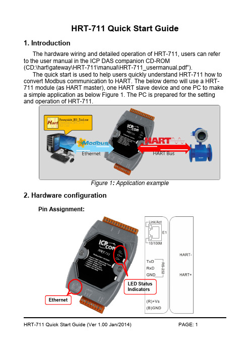
HRT-711 Quick Start Guide1. IntroductionThe hardware wiring and detailed operation of HRT-711, users can refer to the user manual in the ICP DAS companion CD-ROM(CD:\hart\gateway\HRT-711\manual\HRT-711_usermanual.pdf”).The quick start is used to help users quickly understand HRT-711 how to convert Modbus communication to HART. The below demo will use a HRT-711 module (as HART master), one HART slave device and one PC to make a simple application as below Figure 1. The PC is prepared for the setting and operation of HRT-711.Figure 1: Application example2. Hardware configurationPin Assignment:LED StatusIndicatorsEthernetPin Name GroupDescriptionHART+ HART Positive of HART HART- Negative of HART+VS Power SourceV+ of Power Supply(+10 ~ +30 VDC) GND GND of Power Supply TXD Configuration Transmit Data of RS-232RXD Receive Data of RS-232GND GND of RS-232E1Modbus/TCPEthernet RJ45 connector for Modbus/TCPDIP Switch:If user set the DIP switch in the backplane of HRT-711 to be “Default” position, HRT-711 will run in the default mode.Jumper:Jumper DescriptionJP2Enable/Disable hardware WDT. (Default setting is enable)NOTE: Please do not disable the hardware WDT. JP3For updating firmware. (Default setting is on 1 and 2)NOTE: Please do not switch to 2 and 3 when in normal operation. JP4 The jumper can provide HART bus with 250 Ω (1/4 W) resistor. When the pin 1&2 of JP4 is closed, the resistor will connect to HART bus.When the pin 2&3 of JP4 is closed or JP4 without jumper connected,it will disconnect the resistor from HART bus. By default, the pin1&2 of JP4 is closed.LED Indicator:LEDStatus DescriptionETHBlink Blink every 0.2 second :Receiving Ethernet packet Blink every 3 second :The network function is normal OffEthernet ErrorHARTBlinkBlink every 1 second :The HRT-711 is in the initialing procedure Blink every 0.5 second :The HRT-711 is handling the burst frame sent from HART deviceSolid The HRT-711 is in the normal status Off Firmware is not loaded ERRBlink HART communication error OffHART communication is goodRS-232 connection: Without CA-0910With CA-0910HART network wiring:3. Install HG_Tool Utility[ Install .NET Compact Framework ](1) When executing utility, the .NET Framework 2.0 or above must be installed first. If the .NET Framework 2.0 or above exists in the PC, please omit the step.(2) User can download and Install .NET Compact Framework from the below website.◆ Microsoft .Net Framework Version 2.0:/downloads/details.aspx?FamilyID=0856eacb-4362-4b0d-8edd-aab15c5e04f5&DisplayLang=en◆ Microsoft .Net Framework Version 3.5:/downloads/details.aspx?familyid=333325FD-AE52-4E35-B531-508D977D32A6&displaylang=en[ Install HRT-711 Utility ](1) Users can download the installation file of “HRT-711 Utility ” from the CD- (“CD:\hart\gateway\hrt-711\utilities\”) or ICP DAS web site :“ftp:///pub/cd/fieldbus_cd/hart/gateway/hrt-711/utilities/”(2) Execute the “HRT-711 Utility x.x.x.x.exe ” file to install the utility.(3) After finishing the installation of the HRT-711 Utility, users can run theutility. (refer to the path in the below figure)Windows XP Windows 7&84. Communication testStep 1: Connect PC, HRT-711 and HART slave device according to figure1.Step 2: Swtich the DIP switch to the “Init ” position.Step 3: Turn on the power of the HRT-711.Step 4: Wait for the “HART ” LED indicator to be always on status. If theled always flashes, please check the HART network wiring. It means the HRT-711 can’t connect to the HART slave devices.Step 5: Execute the HRT-711 utility.Step 6: Click “HART to Modbus ”Step 7: Select HRT-711 and ComPort in the communication settings.Step 8: Click “Connect” button.Step 9: Wait for the traffic light changes into “green” light. If the traffic light always keeps in the “yellow” light, it means the PC can’t connectto HRT-711, please check the RS-232 connection.Step 10: Click the “Device Information”icon. Then select the default command or user command and right-click the mouse to choosethe “Basic Operation” option to get the information of thecorresponding HART command.The information of HART command 0Step 11: Close all window to back to the main form in Step 6, and then click the Ethernet to configure network.Step 12: Switch the DIP switch to the “Normal” position then power cycle the module.Step 13: When the Ethernet LED on the RJ-45 is on, click Search Servers to search all ICPDAS devices.Step 14: Double click HRT-711 in the list to assign network parameters.Then click OK to apply new setting when finish configuration.Step 15: Users now can read HART device process variable from Modbus.There are many Modbus/TCP client software to test. (Ex: ModbusUtility) The following figure is an example to read Cmd 3 processvariables.。
ADAM4017
快速入门手册一、的概述是位通道的模拟量输入模块,可以采集电压、电流等模拟量输入信号。
它为所有通道都提供了可编程的输入范围,这些模块为工业测量和监控的应用中提供很好的性价比;而且它的模拟量输入通道和模块之间还提供了的电压隔离,这样就有效的防止模块在受到高压冲击时而损坏。
支持路差分,路单端信号,输入范围,,,,,。
如果测试电流信号,需在该通道的输入端口并联一欧姆的精密电阻。
支持路差分信号,还支持协议。
各通道可独立设置其输入范围,同时在模块右侧使用了一个拨码开关来设置和正常工作状态的切换,还增加了的输入范围,测量电流时,不需要外接电阻,只需打开盒盖,设置跳线到△即可。
:通道:通道差分,通道单端输入范围:毫伏电压输入:和电压输入:和电流输入:(需外接Ω电阻)模块按工程单位的方式给主机数据(,,)跳线设置: .默认设置是六通道差分,两通道单端.的技术说明ADAM-4017 差分通道输入(0 通道~5 通道)二、硬件连线ADAM-4017 单端输入(6 通道,7 通ADAM-4017+ 8 通道模拟量输入模块接线图二线制电流变送器和模拟量输入通道的接线方法变送器的“ ”接供电电源的高电压端,变送器的“”接模块板卡的,接电源对应的低电压端()。
注意在模块板卡的和并联电阻。
三、的使用的应用软件的安装把随机附带光盘放入计算机的光驱中,出现如下画面:选择安装选项,出现如下安装界面:根据后续的软件安装提示,完成的安装。
机上就会出现的软件如下图的快速使用1.选中 COM1 或 COM2,点击工具栏快捷键 search:2.弹出“Se arch Ins talled M odules ”窗口,提示扫描模块的范围,允许输入0~255。
RS-485 网络扫描如下图所示3.点击模块,进入测试/配置界面:4.ADAM-4017+还支持Modbus协议,如下所示:(Modbus寄存器支持列表请见说明书)5.终端(Terminal)在 TOOL 菜单,选择 Terminal 功能,弹出一个【Terminal】对话框,用于测试命令。
宏电H7710DTUGPRS远传实例
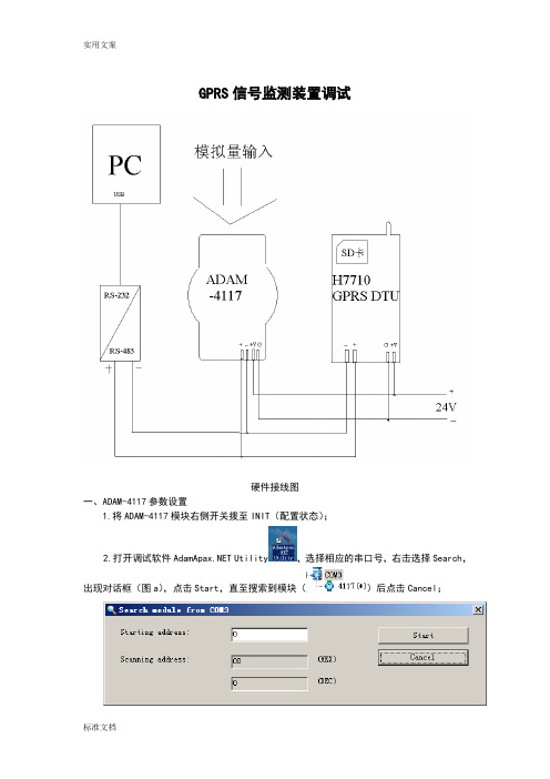
GPRS信号监测装置调试硬件接线图一、ADAM-4117参数设置1.将ADAM-4117模块右侧开关拨至INIT(配置状态);2.打开调试软件 Utility,选择相应的串口号,右击选择Search,出现对话框(图a),点击Start,直至搜索到模块()后点击Cancel;图a3.点击4117(*),配置并保存相应参数,如图(b)。
点击右上角的“Apply change”保存设置到模块的芯片里。
图b二、宏电H7710 GPRS DTU模块参数设置1.断电,打开调试软件sscom32.exe,选择相应串口号,设置相应参数如图c(修改参数的波特率一直为57600);图c2.按住空格键,通电,直至出现图d现象;图d3.按照帮助指示输入“H”,出现主菜单(图e),输入“C”,再输入密码“1234”,回车,进入DTU配置(C)菜单(图f);图e 图f 图g4.输入“3”,进入“数据服务中心设置(DSC)”菜单(图g),输入“1”,配置“DSC IP地址(公网地址,http//:192.168.1.1)”,;输入“2”,配置“DSC 域名”;(注:若已配置固态IP地址,则无需配置域名,即配置域名时按回车键即可;若使用动态IP地址,则将IP地址设为0.0.0.0,域名改为相应的域名地址)输入“3”,配置“DSC 通讯端口”,端口号自己定义,但必须与读取时端口号设置一致;输入“4”,配置“DNS IP地址”,,一般设为主站的DNS IP地址;输入“r”,保存设置输入Y或者N。
5.输入“4”进入“用户串口设置”菜单(图h)图h 图i输入“1”,配置波特率(图i),一般采用9600bps,故输入“4”,再输入“r”返回菜单;输入“2”,配置数据位,一般设为8;输入“3”,配置校验位,一般设为无校验位,故输入“1”,再输入“r”返回菜单;输入“4”,配置停止位,一般设为1;输入“r”,返回主菜单。
6.输入“5”,进入“特殊选项设置”菜单(图j)图j输入“6”,配置“通讯协议选择(透明 0/DDP协议 1)”,一般选择透明,故输入“0”;输入“7”,配置“网络连接方式(UDP 0/TCP 1)”,一般采用TCP连接方式,故输入“1”;输入“r”,再输入“r”返回主菜单。
adam7017模块说明书

adam7017模块说明书
1、信号接入方法:一个adam7017模块可接入6路差动输入+2路单端输入,或者接入8路差动输入(需跳线设置)。
我们现场使用一般都是每一个模块接入8路差动输入,接法就是分别将每一路信号的+端和一端接到adam7017模块上对应的每一路通道的+和一端子上去。
2、供电方法:adam7520模块和adam7017模块都是使用+24V电源供电,多个模块使用的情况下一般只需接入一路+24V电源,再将其余模块并联接入+24V电源即可。
3、通讯连接方法:adam7017模块和adam7520模块之间通过RS485通讯,一个7520模块可以搭配多个adam7017模块,连接方法是将每一个adam7017模块的DATA端并联接入7520
模块的DATA端即可。
再给每一个adam7017模块分配一个不同的ID号,则7520模块就可根据不同的ID号区别出是那个adam7017模块发送过来的数据。
完成adam7017和7520模块的接线之后就可以对adam7017进行设置和通讯了。
由于每一个adam7017出厂默认ID号都为1,当多个adam7017并联使用时,必须将每一个adam7017模块的ID号都作更改:
1. 安装好威达IPC模块调试软件。
2. 因为adam7017 模块出厂默认ID 都相同,所以先对其中一个adam7017 模块上电,其他的模块断电(可以将其他模块的电压端子拔出)。
以上就是adam7017 模块说明书。
ADAM-4117测试文档
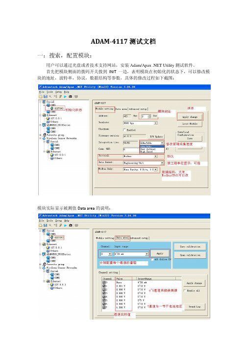
ADAM-4117测试文档一:搜索,配置模块:用户可以通过光盘或者技术支持网站,安装Adam/Apax .NET Utility测试软件。
首先把模块侧面的拨码开关拨到INIT一边,表明模块在初始化的状态下,可以修改模块的地址,波特率,协议,数据结构等参数,具体的修改过程如下截图:模块实际显示被测值Data area的说明:初始化状态下的校准功能,一般情况下,用户无需自行校准。
当模块使用几年后,可能会产生一些零点漂移,在这种情况下,如果您有标准信号源,您可以自行校准,也可以寄到研华维修部门来校准。
校准过程如下,只需校准一个通道,所有通道便都已经校准。
按照界面显示值,直接校准即可。
Trend Log画图功能,可以把采集到的数据,按照指定的路径和方式保存起来,格式为Excel,命名为WaveScanLog_Adam4117(可以有保存的时间显示)或者HistoryLog_Adam4117说明如下:保存后的表格形式如下:初始化高级设置的界面:块就可以再正常状态下工作了。
二:命令测试1.Modbus命令测试在英文说明书的附录B部分有寄存器地址的说明,如下:先把模块配置成Modbus协议,截图如图下:Modbus协议下,在CH7通道Vin7+和Vin7管脚间-接1.5V干电池,其他通道悬空,显示数值如下:用软件的测试功能,测试结果如下:用普通的串口调试助手,发送Modbus指令,读取八个通道的数值。
注意::模拟量占一个字长(16bit),返回值用4个十六进制数表示一个字长,即一个通道注意的读出值;若模块为16位的,则模拟量0~10V对应于十进制的0~65535。
2.ASCII(研华协议)命令测试在英文说明书中,有详细的指令说明,如下的指令表:用软件的测试结果如下:3.Burn-out断线检测功能测试ADAM-4117在输入4~20ma信号输入时,有短线检测的功能,当CH0设定输入范围为4~20ma ,即显示Burn,表明断线。
ADAM-4117模块使用手册

ADAM-4117快速入门手册一、ADAM-4117概述ADAM-4117是16位A/D 、8通道的模拟量输入模块,可以采集电压、电流等模拟量输入信号,并且为所有通道都提供了独立的可编程的输入范围。
在工业测量和监控的应用中,ADAM-4117具有良好的性价比。
它不仅能够用于恶劣的环境中,而且还具有更加坚固型的设计。
ADAM-4117支持8路差分信号,还支持MODBUS 协议。
在模块的右侧有一个白色的拨码开关来设置初始化状态(INIT*)和正常工作状态的切换。
ADAM-4117具有4-20ma 、0-20ma 、±20ma 等电流量程,当您需要测量电流时,不需要外接电阻,只需打开盒盖,按照电路板上的标识来设置跳线即可。
ADAM-4117规格说明AI 模拟量输入●有效分辨率:16位●通道:8路差分,可独立设置量程●高共模电压:200Vdc●通讯协议:ASCII命令,Modbus协议●输入类型:mV,V(支持单双极性),mA●输入量程:0~150mV, 0~500mV, 0~1V, 0~5V, 0~10V, 0~15V,±150 mV, ±500 mV,±1V, ±5 V, ±10 V, ±15V, 0~20mA,±20 mA, 4~20mA●隔离电压:3000VDC●过压保护:±60V●采样速率:10/100 采样点每秒(通过测试软件设置)●输入内阻:电压20MΩ,电流120Ω●精确度:电压模式:±0.1% or better 电流模式:±0.2% or better●零点漂移:±6μV/℃●跨度漂移:±25 ppm/° C●共模抑制(CMR)@50/60Hz dB min●内置看门狗●内置TVS/ESD保护●功耗1.2W@24VDC跳线设置:当ADAM-4117测量电流时,需要跳线。
ADAM-4117模块使用手册

ADAM-4117快速入门手册、ADAM-4117概述ADAM-411是16位A/D 、8通道的模拟量输入模块,可以采集电压、电流等 模拟量输入信号,并且为所有通道都提供了独立的可编程的输入范围。
在工业测量和监控的应用中,ADAM-411;具有良好的性价比。
它不仅能够用于恶劣的环境 中,而且还具有更加坚固型的设计。
ADAM-4117支持8路差分信号,还支持 MODBU 协议。
在模块的右侧有一个 白色的拨码开关来设置初始化状态 (INIT*)和正常工作状态的切换。
ADAM-4117 具有4-20ma 0-20ma 土 20ma 等电流量程,当您需要测量电流时,不需要外接 电阻,只需打开盒盖,按照电路板上的标识来设置跳线即可。
ADAM-41170~150mV,0~500mV,0~1V, 0~5V, 0~10V, 0~15V, ± 150 mV, ± 500mV, ± 1V, ± 5 V, ± 10 V, ± 15V, 0~20mA, ± 20 mA, 4~20mA隔离电压:3000VDC规格说明AI 模拟量输入有效分辨率:16位通道:8路差分,可独立设置量程 高共模电压:200Vdc通讯协议:ASCII 命令,Modbus 协议输入类型:mV V (支持单双极性),mA 输入量程过压保护:土60V采样速率:10/100采样点每秒(通过测试软件设置)输入内阻:电压20MQ,电流120Q精确度:电压模式:土% or better 电流模式:土% or better零点漂移:土6yVC跨度漂移:土25 ppm/ ° C共模抑制(CMR @50/60Hz dB min内置看门狗内置TVS/ESD保护功耗@24VDC 跳线设置:当ADAM-4117测量电流时,需要跳线。
将盒盖拆开,可以看到电路板上有八个跳线,按照下图或者按照电路板上的标识进行跳线,测量电流需要将跳线跳到“I”端,测量电压则需要保持跳线在“ V'端的出厂设置不变。
ADAM-4118快速入门手册
ADAM-4118快速入门手册一、ADAM-4118概述ADAM-4118是16位A/D、8通道的热电偶输入模块,可以采集电压、电流热电偶等模拟量输入信号,它支持多种热电偶类型(Type J, K, T, E, R, S, B),并且将测量到的温度以工程量单位(℃)输出给上位机。
为了适应各种应用场合,ADAM-4118的每个通道可以配置成不同的热电偶输入类型。
ADAM-4118支持8路差分信号,还支持MODBUS协议。
在模块的右侧有一个白色的拨码开关来设置初始化状态(INIT*)和正常工作状态的切换。
除了热电偶量程外,ADAM-4118还具有4-20ma、±20ma等电流量程,当需要测量电流时,不需要外接电阻,只需打开盒盖,按照电路板上的标识来设置跳线即可。
ADAM-4118ADAM-4118一分钟快速入门:✧ADAM-4118可以将热电偶(温度)以及电压电流信号转换为RS-485信号,传输到电脑或PLC中✧一般电脑都具有RS-232接口,通过RS-232到RS-485的转换器连接ADAM-4118✧以ADAM-4520为例,电脑通过直连线连接ADAM-4520,4520的DATA+连接4118的DATA+,4520的DATA-连接4118的DATA-。
连线完成后,安装测试软件,通过测试软件对4118进行测试和配置✧ADAM-4118和ADAM-4520都需要供电,4118通电之后,指示灯呈红色闪烁状。
✧更加详细的描述参见下面的内容。
……to be continue……规格说明AI 模拟量输入●有效分辨率:16位●通道:8路差分,可独立设置量程●高共模电压:200Vdc●通讯协议:ASCII命令,Modbus协议●输入类型& 量程范围J 0 ~ 760 ℃K 0 ~ 1370 ℃T -100 ~ 400 ℃E 0 ~ 1000 ℃R 500 ~ 1750 ℃S 500 ~ 1750 ℃B 500 ~ 1800 ℃电压模式50mV, ±100mV, ±500mV, ±1V, ±2.5V电流模式±20 mA, +4~20 mA●隔离电压:3000VDC●过压保护:±60V●采样速率:10/100 采样点每秒(通过测试软件设置)●输入内阻:电压20MΩ,电流120Ω●精确度:电压模式:±0.1% or better 电流模式& 高速模式:±0.2% or better ●零点漂移:±6μV/℃●跨度漂移:±25 ppm/° C●共模抑制(CMR)@50/60Hz dB min●内置看门狗●内置TVS/ESD保护●功耗1.2W@24VDC跳线设置:ADAM-4118测量电流时需要跳线。
Omega 4117 AC Power Controller 产品说明书
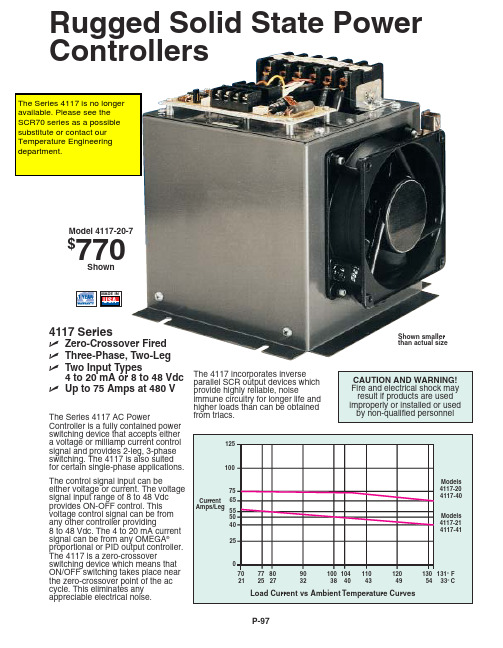
P-97Rugged Solid State Power ControllersThe Series 4117 AC PowerController is a fully contained power switching device that accepts either a voltage or milliamp current control signal and provides 2-leg, 3-phase switching. The 4117 is also suited for certain single-phase applications.The control signal input can beeither voltage or current. The voltage signal input range of 8 to 48 Vdc provides ON-OFF control. This voltage control signal can be from any other controller providing8 to 48 Vdc. The 4 to 20 mA current signal can be from any OMEGA ®proportional or PID output controller.The 4117 is a zero-crossoverswitching device which means that ON/OFF switching takes place near the zero-crossover point of the ac cycle. This eliminates any appreciable electrical noise.4117 SeriesߜZero-Crossover Fired ߜThree-Phase, Two-Leg ߜTwo Input Types4 to 20 mA or 8 to 48 Vdc ߜUp to 75 Amps at 480 VModel 4117-20-7$770ShownShown smaller than actual sizeThe 4117 incorporates inverseparallel SCR output devices whichprovide highly reliable, noiseimmune circuitry for longer life and higher loads than can be obtained from triacs.P-98AccessoriesSpecifications GeneralIsolation Input to Output:2500 Vac or 109Ωdc Isolation Input to Base:2500 Vac or 109Ωdc Ambient Temperature:0 to 55°C (30 to 130°F)Line Frequency: 47 to 63 Hz Enclosure:Heavy duty metal frame, voltage isolatedPower Terminals:Convenient high pressure connectors to accept #4 to #12 wire (no lugs required)Weight:13 lb (5.9 kg) (approx.)Current InputControl Signal Input (3 choices):(1) 4 to 20 mA, (2) External Contact Closure (ON/OFF Control), (3) External 10 K Potentiometer (Manual Adjust)Input Impedance:200 ΩTurn ON Signal:4-6 mA dc, typical Full ON Signal:18 to 20 mA dc, typicalCycle Time:1 second nominal Line Voltage Compensation:Automatic, over range of 40 to 100% of power (can be disabled)Indications:Red LED indicates load power "ON"Power Limit Adjustment:0 to 100%, internalpotentiometer, for testing or limit protectionVoltage InputControl Signal Range:8 to 48 Vdc Minimum Turn ON Voltage: 8 VdcTurn OFF Voltage:2 Vdc Input Current at 32 Vdc:20 mA max Reverse Voltage: up to 48 Vdc Input Isolation Voltage:2500 VRugged Solid State Power Controllerscontroller mounted vertically in still air.CANADA www.omega.ca Laval(Quebec) 1-800-TC-OMEGA UNITED KINGDOM www. Manchester, England0800-488-488GERMANY www.omega.deDeckenpfronn, Germany************FRANCE www.omega.frGuyancourt, France088-466-342BENELUX www.omega.nl Amstelveen, NL 0800-099-33-44UNITED STATES 1-800-TC-OMEGA Stamford, CT.CZECH REPUBLIC www.omegaeng.cz Karviná, Czech Republic596-311-899TemperatureCalibrators, Connectors, General Test and MeasurementInstruments, Glass Bulb Thermometers, Handheld Instruments for Temperature Measurement, Ice Point References,Indicating Labels, Crayons, Cements and Lacquers, Infrared Temperature Measurement Instruments, Recorders Relative Humidity Measurement Instruments, RTD Probes, Elements and Assemblies, Temperature & Process Meters, Timers and Counters, Temperature and Process Controllers and Power Switching Devices, Thermistor Elements, Probes andAssemblies,Thermocouples Thermowells and Head and Well Assemblies, Transmitters, WirePressure, Strain and ForceDisplacement Transducers, Dynamic Measurement Force Sensors, Instrumentation for Pressure and Strain Measurements, Load Cells, Pressure Gauges, PressureReference Section, Pressure Switches, Pressure Transducers, Proximity Transducers, Regulators,Strain Gages, Torque Transducers, ValvespH and ConductivityConductivity Instrumentation, Dissolved OxygenInstrumentation, Environmental Instrumentation, pH Electrodes and Instruments, Water and Soil Analysis InstrumentationHeatersBand Heaters, Cartridge Heaters, Circulation Heaters, Comfort Heaters, Controllers, Meters and SwitchingDevices, Flexible Heaters, General Test and Measurement Instruments, Heater Hook-up Wire, Heating Cable Systems, Immersion Heaters, Process Air and Duct, Heaters, Radiant Heaters, Strip Heaters, Tubular HeatersFlow and LevelAir Velocity Indicators, Doppler Flowmeters, LevelMeasurement, Magnetic Flowmeters, Mass Flowmeters,Pitot Tubes, Pumps, Rotameters, Turbine and Paddle Wheel Flowmeters, Ultrasonic Flowmeters, Valves, Variable Area Flowmeters, Vortex Shedding FlowmetersData AcquisitionAuto-Dialers and Alarm Monitoring Systems, Communication Products and Converters, Data Acquisition and Analysis Software, Data LoggersPlug-in Cards, Signal Conditioners, USB, RS232, RS485 and Parallel Port Data Acquisition Systems, Wireless Transmitters and Receivers。
ADAM-4117快速入门手册

ADAM-4117快速入门手册一、ADAM-4117概述ADAM-4117是16位A/D、8通道的模拟量输入模块,可以采集电压、电流等模拟量输入信号,并且为所有通道都提供了独立的可编程的输入范围。
在工业测量和监控的应用中,ADAM-4117具有良好的性价比。
它不仅能够用于恶劣的环境中,而且还具有更加坚固型的设计。
ADAM-4117支持8路差分信号,还支持MODBUS协议。
在模块的右侧有一个白色的拨码开关来设置初始化状态(INIT*)和正常工作状态的切换。
ADAM-4117具有4-20ma、0-20ma、±20ma等电流量程,当您需要测量电流时,不需要外接电阻,只需打开盒盖,按照电路板上的标识来设置跳线即可。
ADAM-4117ADAM-4117一分钟快速入门:✧ADAM-4117可以将电压电流信号转换为RS-485信号,传输到电脑或PLC中✧一般电脑都具有RS-232接口,通过RS-232到RS-485的转换器连接ADAM-4117✧以ADAM-4520为例,电脑通过直连线连接ADAN-4520,4520的DATA+连接4117的DATA+,4520的DATA-连接4117的DATA-。
连线完成后,安装测试软件,通过测试软件对4117进行测试和配置✧ADAM-4117和ADAM-4520都需要供电,4117通电之后,指示灯呈红色闪烁状。
✧更加详细的描述参见下面的内容。
……to be continued……规格说明AI 模拟量输入●有效分辨率:16位●通道:8路差分,可独立设置量程●高共模电压:200Vdc●通讯协议:ASCII命令,Modbus协议●输入类型:mV,V(支持单双极性),mA●输入量程:0~150mV, 0~500mV, 0~1V, 0~5V, 0~10V, 0~15V,±150 mV, ±500 mV,±1V, ±5 V, ±10 V, ±15V, 0~20mA,±20 mA, 4~20mA●隔离电压:3000VDC●过压保护:±60V●采样速率:10/100 采样点每秒(通过测试软件设置)●输入内阻:电压20MΩ,电流120Ω●精确度:电压模式:±0.1% or better 电流模式:±0.2% or better●零点漂移:±6μV/℃●跨度漂移:±25 ppm/° C●共模抑制(CMR)@50/60Hz dB min●内置看门狗●内置TVS/ESD保护●功耗1.2W@24VDC跳线设置:当ADAM-4117测量电流时,需要跳线。
ADAM-40174017+快速入门手册范本
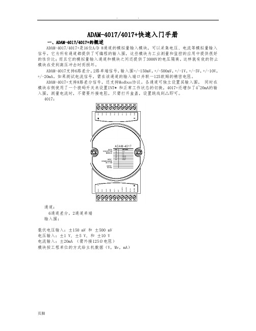
ADAM-4017/4017+快速入门手册一、ADAM-4017/4017+的概述ADAM-4017/4017+是16位A/D 8通道的模拟量输入模块,可以采集电压、电流等模拟量输入信号。
它为所有通道都提供了可编程的输入围,这些模块为工业测量和监控的应用中提供很好的性价比;而且它的模拟量输入通道和模块之间还提供了3000V的电压隔离,这样就有效的防止模块在受到高压冲击时而损坏。
ADAM-4017支持6路差分,2路单端信号,输入围+/-150mV,+/-500mV,+/-1V,+/-5V,+/-10V,+/-20mA。
如果测试电流信号,需在该通道的输入端口并联一125欧姆的精密电阻。
ADAM-4017+支持8路差分信号,还支持Modbus协议。
各通道可独立设置其输入围,同时在模块右侧使用了一个拨码开关来设置INT* 和正常工作状态的切换,4017+还增加了4~20mA的输入围,测量电流时,不需要外接电阻,只需打开盒盖,设置跳线到△即可。
4017:通道:6通道差分,2通道单端输入围:毫伏电压输入:±150 mV 和±500 mV电压输入:±1 V, ±5 V, 和±10 V电流输入:±20mA (需外接125Ω电阻)模块按工程单位的方式给主机数据(V,Mv,mA)ADAM-4017+跳线设置:1.JP9 和 JP10(默认设置是六通道差分,两通道单端)JP9,JP10 六通道差分,两通道单端八通道差分2.JP1~JP8JP1~JP8 20mA输入围电压输入围映射到通道3.JP13 系统处于正常模式系统处于初始模式ADAM-4017+的技术说明通道数8输入类型mV,V,mA输入围+/-150mV, +/-500mV, +/-1mV, +/-5mV, +/-10mV,+/-20mV, 4~20mA隔离电压3000VDC最高额定电压+/-35V采样速率10个采样点/秒(总的)输入阻抗20MΩ精确度≤+/-0.1%功率 1.2WI/0连接器类型 十针连接器二、 ADAM-4017/4017+硬件连线ADAM-4017 差分通道输入(0通道~5通道)ADAM-4017单端输入(6通道,7通1.ADAM-4017/4017+模块简单控制接线图主机RS-232/ RS-485转换器+ 一10V~30VDC电源DA TA+ DA TA-+Vs GND三、 ADAM-4000 Utility 的使用1.ADAM-4000的应用软件-ADAM Utility 的安装把ADAM4000 随机附带光盘放入计算机的光驱中,出现如下画面:选择ADAM4000 Utility 安装选项,出现如下安装界面:ADAM-4017+ 8通道模拟量输入模块接线图根据后续的软件安装提示,完成ADAM4000 Utility 的安装。
Adam Equipment DUNE Series 权重仪操作手册说明书
Adam EquipmentDUNE SERIES(P.N. 9384, Revision A, April 2008)1.0 CONTENTS1.0 CONTENTS (3)2.0 INTRODUCTION (3)3.0 SET UP (4)3.1 UNPACKING AND SETTING UP YOUR SCALE (4)3.2 LOCATING AND PROTECTING YOUR SCALE (5)4.0 BASIC OPERATION (6)4.1 TURING ON THE SCALE (6)4.2 ZEROING / TARE (6)4.4 WEIGHING (6)5.0 FUNCTIONS (7)5.1 AUTO POWER OFF (7)6.0 CALIBRATION (7)7.0 TROUBLE SHOOTING (8)7.1 ERROR MESSAGES (8)7.2 REPLACEMENT PARTS AND ACCESSORIES (8)8.0 SPECIFICATIONS (9)9.0 WARRANTY STATEMENT (10)2.0 INTRODUCTIONThank you for purchasing the Dune TM compact scales, Every Dune is equipped with the features you really need: AC adapter, auto‐calibration through the keypad, low‐battery indicator, and overload indicator. With its alternate battery operation, splash‐proof key pad, and sturdy plastic construction throughout, the Dune will deliver accurate readings both indoors and out.3.0 SET UP3.1 UNPACKING AND SETTING UP YOUR SCALE1) Remove the top pan and card board packaging between top pan and machine.2) Connect the power adapter to the socket on the back of the machine.3.2 LOCATING AND PROTECTING YOUR SCALEIn order to keep you scale functioning at its best we suggest that you do the following:Avoid extremes of temperature. Do not place in direct sunlight or near air conditioning vents.Make sure the scale is located on a strong table and free from vibration.Avoid unstable power sources. Do not use near large users of electricity such as welding equipment or large motors. Do not mix batteries and use only the factory approved power adapter supplied with the machine. Do not use batteries and the AC adapter at the same time.Keep free from vibration. Do not place near heavy or vibrating machinery.Avoid high humidity that might cause condensation. Keep away from direct contact with water. Do not spray or immerse the scales in water.Do not place near open windows, air ‐conditioning vents or fans that may cause a draft and unstable readings.Keep the scales clean. Do not stack material on the scale / balance when it is not in use.4.0 BASIC OPERATION4.1 TURING ON THE SCALEPlug in the unit using the AC adapter or use batteries. Do not use battery power and the AC adapter at the same time.1)To turn on press the [on/off] key once and release. All of the segments onthe display will light up, then the display shows zero >0<2)The scale is ready to be use.3)To turn the scale off after use press the [on/off] key again. There is an autopower‐off function that will automatically turn the unit off after 4 min of inactivity or no change in the weight reading.4.2 ZEROING / TAREYou can press the [Tare] key to set a new zero point and show the zero reading if the weight reading is less than 4% of the total of the maximum capacity of the scale. This may be necessary if the weight is not reading zero with nothing on the platform. The zero indicators will light up: >0<.If you are using a container to weigh then you can place this on the platform and press the [Tare] key, providing the container weight is more than 4% of the maximum capacity of the scale, the display will show zero and tare indicator will light up. You can then weigh your object in the container. Taring weight subtracts from the total scale capacity.Note: When the container is removed a negative value will be shown. If the scale was tared just before removing the container, this value is the gross weight of the container plus all products which were removed.4.4 WEIGHINGTo determine the weight of a sample, first tare an empty container (if used), then place the sample in the container. The display will show the weight and the unit of weight currently in use.5.0 FUNCTIONS5.1 AUTO POWER OFFThe auto power off helps conserve power when using on battery or the AC adapter, the machine will automatically turn off after 4 min of inactive use or no change in the displayed weight.6.0 CALIBRATIONBefore calibrating the Dune series it is best to turn on the unit for about 1 min to let the components warm up.1)Press [on/off] key to turn the power on, if it is not already.2)Press and hold the [Unit] key, until “CAL” is displayed3)Remove any weight from the pan.4)Press the [Unit] key, the display will flash “CAL” them will show the cal massrequired. If the cal mass is not displayed then the machine is not stable or is not within a zero range. Turn off the unit and try zeroing the display before trying another calibration.5)Place the appropriate calibration mass on the scale:Model Calibration MassDCT 201 200gDCT 2000 2000gDCT 5000 5000g6)After the stable reading the display will show “PASS” then revert to theweighing mode. If the calibration does not pass the display will show “FAIL”and shut off.7) The calibration is now finished. If the calibration is correct, the display willshow the weight value.NOTE: If the calibration fails retry, if it still fails then there may be damage to the mechanics or an issue with the power. If you do not follow the procedures in a timely manner the machine will automatically switch off and the calibration will not be accepted.7.0 TROUBLE SHOOTING7.1 ERROR MESSAGESIf an error message is shown, repeat the step that caused the message. If the error message is still shown then contact your dealer for support.ERROR CODE DESCRIPTION POSSIBLE CAUSESO-Ld Overload Remove weight from the pan. Makesure the machine is reading zerobefore weighing. Do not over loadthe pan. If the problem recurscalibrate. Possible damage to themechanics.OUt2 Out of Zero reading Make sure the pan is fitted correctly.Make sure nothing is touching thepan when turning on the unit.Calibrate the machine. Possibledamage to the mechanics.UnSt Unstable Make sure the balance is on a flatsurface and away from vibration.Possible damage to the mechanics. LO or Low Battery indicator Change the batteries or use on thepower adapter.ErrE E‐Prom error Software error turn off and restart.Contact Adam Equipment or yourdealer for further assistance.No Power when turning on Change the batteries or use on thepower adapter.7.2 REPLACEMENT PARTS AND ACCESSORIESIf you need to order any spare parts and accessories, contact your supplier or Adam Equipment. A partial list of the more common items follows:Part Number Description9402 AC adapter(Country Dependent)9401 Plastic pan8.0 SPECIFICATIONSModel # DCT‐201 DCT‐2000 DCT‐5000 Maximum Capacity 200g 2000g 5000gReadability 0.1g 1g 2gRepeatability (Std Dev) 0.1g 1g 2gLinearity ± 0.2g 2g 4gUnits of Measure g / oz g / lb /ozStabilisation Time 2 secondsOperating Temperature0ºC to 40ºC 32ºF to 104ºFPower Supply 12VAC @ 150mA adapter or 6x AA batteries Calibration Push button calibration using external mass Calibration Mass 200g 2000g 5000g Display 5 digit LCD display 15mm high Balance Housing ABS PlasticPan Size 145 x 145mm5.8” x 5.8”Overall Dimensions (w x d x h) 145 x 210 x 40mm 5.8" x 8.3" x 1.6"Gross Weight 1kg, 2.2lbFeatures Low battery, Stable and Zero indications9.0 WARRANTY STATEMENTAdam Equipment offers Limited Warranty (Parts and Labour) for the components failed due to defects in materials or workmanship. Warranty starts from the date of delivery.During the warranty period, should any repairs be necessary, the customer must inform the supplier or Adam Equipment. The company or its authorised Technician reserves the right to repair or replace any components at its own discretion. Any shipping costs involved in sending the faulty units to a service centre is the customers responsibility.The warranty will cease to operate if the equipment is not returned in the original packaging and with correct documentation for a claim to be processed. All claims are at the sole discretion of Adam Equipment.This warranty does not cover equipment where defects or poor performance is due to misuse, accidental damage, exposure to radioactive or corrosive materials, negligence, faulty installation, unauthorised modifications or attempted repair or failure to observe the requirements and recommendations as given in this User Manual.Repairs carried out under the warranty does not extend the warranty period. Components removed during the warranty repairs become the company property.The statutory right of the purchaser is not affected by this warranty. The terms of this warranty is governed by the English Law. For complete details on Warranty Information, see the terms and conditions of sale available on our web‐site.Manufacturer’s Declaration of ConformityThis product has been manufactured in accordance with theharmonised European standards, following the provisions of thebelow stated directives:Electro Magnetic Compatibility Directive 2004/108/ENLow Voltage Directive 73/23/EECAdam Equipment Co. Ltd.Bond Avenue, Denbigh EastMilton Keynes, MK1 1SWUnited KingdomFCC COMPLIANCEThis equipment has been tested and found to comply with the limits for a Class A digital device, pursuant to Part 15 of the FCC Rules. These limits are designed to provide reasonable protection against harmful interference when the equipment is operated in a commercial environment. The equipment generates, uses, and can radiate radio frequency energy and, if not installed and used in accordance with the instruction manual, may cause harmful interference to radio communications. Operation of this equipment in a residential area is likely to cause harmful interference in which case the user will be required to correct the interference at his own expense.Shielded interconnect cables must be employed with this equipment to insure compliance with the pertinent RF emission limits governing this device.Changes or modifications not expressly approved by Adam Equipment could void the user's authority to operate the equipment.WEEE COMPLIANCEAny Electrical or Electronic Equipment (EEE) component or assembly of parts intended to be incorporated into EEE devices as defined by European Directive 2002/95/EEC must be recycled or disposed using techniques that do not introduce hazardous substances harmful to our health or the environment as listed in Directive 2002/95/EC or amending legislation. Battery disposal in Landfill Sites is more regulated since July 2002 by regulation 9 of the Landfill (England and Wales) Regulations 2002 and Hazardous Waste Regulations 2005.ADAM EQUIPMENT is an ISO 9001:2000 certified global company with more than 35 years experience in the production and sale of electronic weighing equipment.For a complete listing of all Adam scales and balances visit our website at:© Copyright by Adam Equipment Co. Ltd. All rights reserved. No part of this publication may be reprinted or translated in any form or by any means without the prior permission of Adam Equipment.Adam Equipment reserves the right to make changes to the technology, features, specifications and design of the equipment without notice.All information contained within this publication is to the best of our knowledge timely, complete and accurate when issued. However, we are not responsible for misinterpretations which may result from the reading of this material.The latest version of this publication can be found on our Website.Head Office:Adam Equipment Co. Ltd.Bond Avenue,Milton Keynes,MK1 1 SWTel: +44 (0)1908 274545FaX: +44 (0)1908 641339**********************.ukFor regional office worldwide visit 。
ADAM-4117/4118自动滤波功能解决干扰问题
ADAM-4117/4118自动滤波功能解决干扰问题
佚名
【期刊名称】《测控技术》
【年(卷),期】2008(27)8
【摘要】研华自动化的强固型数据采集模块ADAM-4100系列产品,专为恶劣环境下的可靠操作而设计,能够在宽温度工作范围,宽电源输入范围,甚至在噪音干扰环境中操作。
ADAM-4100系列中,模拟量输入采集模块ADAM-4117和热电偶采集模块ADAM-4118均具备了自动滤波器功能,可以根据噪音的最大频率来自动调整滤波参数,从而可以有效过滤干扰,保证信号采集的准确和稳定。
【总页数】1页(P100-100)
【关键词】干扰问题;滤波功能;数据采集模块;输入范围;干扰环境;滤波参数;自动调整;信号采集
【正文语种】中文
【中图分类】TP368.1;TN643
【相关文献】
1.巧用机车信号载频自动切换功能解决邻线干扰问题 [J], 刘连峰
2.ADAM-4117/4118自动滤波功能成功解决干扰问题/华北工控特种计算机闪耀08中国消费电子展 [J],
3.关于卫星C频段滤波器解决5G基站干扰问题的研究 [J], 秦恒;潘宇
4.关于卫星C频段滤波器解决5G基站干扰问题的研究 [J], 秦恒;潘宇
5.ADAM-4117/4118自动滤波功能成功解决干扰问题 [J],
因版权原因,仅展示原文概要,查看原文内容请购买。
- 1、下载文档前请自行甄别文档内容的完整性,平台不提供额外的编辑、内容补充、找答案等附加服务。
- 2、"仅部分预览"的文档,不可在线预览部分如存在完整性等问题,可反馈申请退款(可完整预览的文档不适用该条件!)。
- 3、如文档侵犯您的权益,请联系客服反馈,我们会尽快为您处理(人工客服工作时间:9:00-18:30)。
ADAM-4117快速入门手册一、ADAM-4117概述ADAM-4117是16位A/D、8通道的模拟量输入模块,可以采集电压、电流等模拟量输入信号,并且为所有通道都提供了独立的可编程的输入范围。
在工业测量和监控的应用中,ADAM-4117具有良好的性价比。
它不仅能够用于恶劣的环境中,而且还具有更加坚固型的设计。
ADAM-4117支持8路差分信号,还支持MODBUS协议。
在模块的右侧有一个白色的拨码开关来设置初始化状态(INIT*)和正常工作状态的切换。
ADAM-4117具有4-20ma、0-20ma、±20ma等电流量程,当您需要测量电流时,不需要外接电阻,只需打开盒盖,按照电路板上的标识来设置跳线即可。
ADAM-4117ADAM-4117一分钟快速入门:✧ADAM-4117可以将电压电流信号转换为RS-485信号,传输到电脑或PLC中✧一般电脑都具有RS-232接口,通过RS-232到RS-485的转换器连接ADAM-4117✧以ADAM-4520为例,电脑通过直连线连接ADAN-4520,4520的DATA+连接4117的DATA+,4520的DATA-连接4117的DATA-。
连线完成后,安装测试软件,通过测试软件对4117进行测试和配置✧ADAM-4117和ADAM-4520都需要供电,4117通电之后,指示灯呈红色闪烁状。
✧更加详细的描述参见下面的内容。
……to be continued……规格说明AI 模拟量输入⚫有效分辨率:16位⚫通道:8路差分,可独立设置量程⚫高共模电压:200Vdc⚫通讯协议:ASCII命令,Modbus协议⚫输入类型:mV,V(支持单双极性),mA⚫输入量程:0~150mV, 0~500mV, 0~1V, 0~5V, 0~10V, 0~15V,±150 mV, ±500 mV, ±1V, ±5 V, ±10 V, ±15V, 0~20mA,±20 mA, 4~20mA⚫隔离电压:3000VDC⚫过压保护:±60V⚫采样速率:10/100 采样点每秒(通过测试软件设置)⚫输入内阻:电压20MΩ,电流120Ω⚫精确度:电压模式:±0.1% or better 电流模式:±0.2% or better⚫零点漂移:±6μV/℃⚫跨度漂移:±25 ppm/° C⚫共模抑制(CMR)@50/60Hz dB min⚫内置看门狗⚫内置TVS/ESD保护⚫功耗跳线设置:当ADAM-4117测量电流时,需要跳线。
将盒盖拆开,可以看到电路板上有八个跳线,按照下图或者按照电路板上的标识进行跳线,测量电流需要将跳线跳到“I”端,测量电压则需要保持跳线在“V”端的出厂设置不变。
跳线完成后,可以使用万用表测量V+与V-之间,正常应该有120Ω的电阻。
二、ADAM-4117硬件连线如果需要连接二线制变送器,可以参考下图的接线方法。
如果变送器是电流变送器,请注意模块内部的电流跳线。
三、测试软件(Utility)的使用ADAM-4117适用ADAM-4000-5000 Utility(old)或ADAM .Net Utility(new). 下面以ADAM .Net Utility为例,演示ADAM-4117的安装、配置和测试过程。
1. Utility的安装将ADAM-4117盒子里附带的小光盘放入计算机的光驱中,取消自动播放,使用右键打开,先按照如下路径安装Microsoft DotNet framework,即下图中的dotnetfx.exe。
安装完Microsoft .net fx之后,再安装测试软件Advantech Utility:注意:如果PC是Win XXXX/XP操作系统,需要运行的是Win 32下的安装文件安装完成之后,可以通过如下路径打开Adam .net Utility:如果希望使用年代比较久一些的ADAM-4000-5000 Utility,也可以通过光盘上的如下路径安装这个测试软件:2. Adam .net Utility的快速使用Step 1选择连接到ADAM-4117的com口,点击上面的放大镜图标search:注意:如果使用串口扩展卡,扩展出来的com口序号较大(例如com5),可能需要您点击Utility上面Setup菜单中的refresh按钮来显示所有的com口一般情况下,鼠标点击到com1时,右侧setting中的参数无需改变,除非您确认您已经修改了ADAM-4520以及ADAM-4117的串口通讯参数(例如波特率、数据位等)Step 2一般情况下,无需更改弹出窗口的Starting address,直接点击Start即可。
这项参数的含义是从哪个RS-485地址开始搜索,一直搜索到Address 255为止。
Step 3搜索到模块后,可以点击Cancel按钮取消搜索,点击左侧菜单中的模块名称进入模块配置页面。
在上面的Utility画面中,可以配置RS-485 地址(Address)、波特率(Baudrate)、通讯协议(Procotol)等。
修改完毕后,点击右上角的“Apply change”保存设置到模块的芯片里。
注意:上面截图中的ADAM-4117为初始化状态,所以可以修改波特率和通讯协议等参数。
切换初始化状态的开关在模块右侧,拨到INIT为初始化状态(配置状态),拨到Normal为用户正常使用状态。
切换开关的操作必须在模块断电状态下进行才有效。
3. ADAM-4117的MODBUS协议ADAM-4117支持MODBUS RTU协议,在模块初始化状态的情况下,可以在Utility下通过“Protocol”项的下拉菜单将协议更改为“Modbus”。
更改协议之后,将拨码开关拨到Normal,可以通过MODBUS寄存器地址40001~40008来读取CH0~CH8的数值。
更加详细的MODBUS地址对照表参见ADAM-4100系列的英文手册。
Modbus协议读到的数值为16进制或10进制的整数,数值从0-65535,分别对应量程的上下限。
例如,当量程为±10V时,如果输入的电压值为0V,则读取到的Modbus数值为32767。
4. ADAM-4117 的ASCII协议将ADAM-4117的拨码开关拨到Normal状态后上电,用鼠标点一下ADAM-4117所在的com口,再点一下上面的黄色闪电图标,打开Terminal 工具。
如果希望读取ADAM-4117全部8个通道的数值,可以使用的ASCII命令是“#”+“地址”+“回车(cr)”;例如当4117地址为1时,可以发送命令“#01(cr)”.更加详细的ASCII指令表参见ADAM-4100系列英文手册。
注意:在ADAM Utility中,已经默认在ASCII命令后面增加回车,所以看不出来需要使用回车。
如果使用网络上的“串口调试助手”或自己编写程序,那么一定要在命令后面添加回车(对应的ASCII为0D)才会收到4117的回复。
5. 校准(警告:非必要无需自行校准!)ADAM-4117出厂时已经经过校准,所以一般情况下,用户无需自行校准。
当模块使用几年后,可能会产生一些零点漂移,在这种情况下,如果您有标准信号源,您可以自行校准,也可以寄到研华维修部门来校准。
校准过程如下:Step1:将模块右侧的拨码开关拨到INIT状态Step2:点击Zero calibration按钮,会弹出一个对话框提示“请提供0.0mV的电压到模块的CH0通道”。
此时,在CH0通过标准信号源接入0.0mV的信号后,点击“Apply”。
如果您没有接入标准信号源,不小心误点了Zero calibration按钮,请点击弹出窗口右上角的红叉,退出校准过程。
务必不要在没有外接0.0mV信号的情况下点击“Apply”按钮!!!!!注意:如果您使用的不是+/-10V的量程,需要您在CH0输入的信号可能不是0mV,请您按照弹出对话框的提示来输入实际信号!Step3:点击Span calibration按钮,会弹出一个对话框提示“请提供10.0V的电压到模块的CH0通道”。
此时,在CH0通过标准信号源接入10.0V的信号后,点击“Apply”。
如果您没有接入标准信号源,不小心误点了Zero calibration按钮,请点击弹出窗口右上角的红叉,退出校准过程。
务必不要在没有外接10.0mV信号的情况下点击“Apply”按钮!!!!!注意:如果您使用的不是+/-10V的量程,需要您在CH0输入的信号可能不是0mV,请您按照弹出对话框的提示来输入实际信号!四、ADAM-4100的软件编程ADAM-4117的编程,主要的流程就是通过串口发出命令,然后收取模块的回复。
当使用Modbus协议时,通过串口发出的命令就是Modbus命令,具体可以参考Modbus RTU的标准协议内容,由于是公开的通用协议,在此不再赘述。
如果使用 XXXX/XXXX对Modbus进行编程,可以参考下面Step3的例程。
下面主要讲解如何通过ASCII协议来对ADAM-4117模块进行编程。
注意:更加详细的ASCII指令表参见ADAM-4100系列英文手册。
Step1 使用Utility上的Terminal功能测试(参见上面3.4小节中的内容),确认ADAM-4117配置正确,可以接收ASCII命令。
如果使用Visual Studio6.0编程,请参考Step2的内容;如果使用Visual Studio200/XXXX,请参考Step3.Step2 (使用VS6.0编程)参考ADAM-4100系列英文手册18页-23页的内容,有VB 6.0编程的讲解。
如果使用VC、Labview等编程,可以参考如下的程序流程图进行编程注释:1.程序的关键在于将ASCII命令后面的“回车符”发送出去。
不同语言的程序,发送回车符的方式不同。
2.收取回复的时候,回复同样以回车符作为结束,因此需要添加判断,当收到回车符时,收取回复完成。
3.如果使用多个模块,由于RS-485总线的半双工特性,无法同时发送多个命令。
需要在发送每个命令之后增加延时,当收到回复或者判断Timeout之后再发送下一个命令Step3 (使用VSXXXX/XXXX编程)安装光盘里的ADAM .Net class library,安装之后可以在C盘的如下路径找到VB和VC#的例程:C:\Program Files\Advantech\ Class Library\VSXXXX\Samples\Win32对于ADAM-4117模块,使用ASCII协议时,可以参考Adam4017P_18P或Comporttest例程;使用Modbus协议时,可以参考ModbusRTU例程。