三星显示器图纸 (1)
三星s27r350fhc s27r352fhc s27r354fhc s27r356fhc s27r

第 1 章在使用本产品前清洁如果在附近使用超声波加湿器,高光泽机型的表面可能会积聚白色污点。
―如需清洁产品内部,请联系距离最近的 Samsung 客服中心(需收取服务费。
)请勿用手或其他物体挤压产品屏幕。
存在损坏屏幕之风险。
―清洁时请务必小心,因为高级 LCD 的面板和表面很容易刮划。
―清洁时请执行以下步骤。
1 关闭产品和计算机电源。
2 拔下产品的电源线。
―抓住电源插头来插拔电源线,请勿用湿手触摸电源线。
否则,可能会导致触电。
3 使用干净、柔软的干布擦拭本产品。
‒请勿使用含有酒精、溶剂或表面活性剂的清洁剂清洁本产品。
‒请勿将水或清洁剂直接喷到本产品上。
4 将软布在水中浸湿并拧干,然后用布将产品外部擦净。
5 清洁完毕,将电源线连接到产品。
6 接通产品和计算机的电源。
电气安全警告•请勿使用破损的电源线或电源插头,或松动的电源插座。
•请勿将多个产品的电源插头连接到一个电源插座。
•请勿用湿手插拔电源插头。
•请插紧电源插头。
•将电源插头连接到接地的电源插座(仅限 1 级绝缘装置)。
•请勿强行弯折或拉扯电源线。
请小心不要让电源线置于重物下。
•请勿将电源线或产品放在热源附近。
•请用干布擦拭电源线插脚或电源插座周围的灰尘。
注意•产品在使用中时请勿拔下电源线。
•请仅使用 Samsung 为本产品提供的电源线。
请勿使用其他产品的电源线。
•请勿让物体挡住连接电源线的电源插座。
‒出现问题时,必须拔下电源线,以切断本产品的电源。
•从电源插座上拔下电源线时,请抓住电源插头。
警告•请勿将蜡烛、蚊香或香烟放在本产品上。
也不可在热源附近安装本产品。
•请将塑料包装放在儿童无法触及之处。
‒否则,如果儿童玩耍包装袋,可能导致窒息。
•请勿将本产品安装在不稳固或容易震动的表面(摇晃的架子、倾斜的表面等。
);‒否则,本产品可能因掉落而受损和/或导致人身伤害。
‒在震动过大的区域使用本产品可能会损坏本产品或导致火灾。
•请勿将本产品安装在车辆上或有灰尘、湿气(水滴等)、油或烟的地方。
三星 Q70
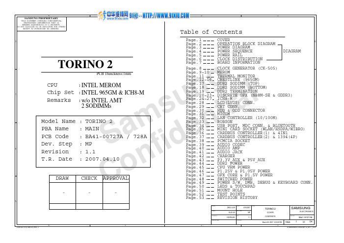
S a m s u n g Co n f i d e n t i a l THERMAL MONITOR 20~23TITLEAPPROVAL384CRT CONN.DDR2 SODIMM (BOTTOM)-Page.BModel Name : Aw/o INTEL AMT A35TORINO 2PBA Name : COVERMEROMPage.CRESTLINE (965GM)AUDIO AMP 40Page.BD Page.POWER SEQUENCEPART NO.12~16MOUNT HOLE Page.Page.39DIAGRAM MAIN 51Page.29CHECKGFX CORE & P1.5V POWER 53Page.8T.R. Date : 228CRemarks : CPU : 46Page.HDD & ODD CONNECTOR DDR2 SODIMM (TOP)Page.Page.48Page.Page.Page.Page.SAMSUNGAUDIO CODEC POWER RAILTEST POINTSPage.INTEL MEROM REV301.12007.04.10Page.1819MP -EXCEPT AS AUTHORIZED BY SAMSUNG.N CONTROLLER (10/100M)36CARDBUS CONTROLLER(2) & 1394(4P)73P1.25V & P1.05V POWER DPage.PCB Code : Page.44CLOCK DISTRIBUTION DDR2 TERMINATION-DATE11DEV. STEP5Page.3437Page.Page.P3.3V_AUX & P5V_AUX USB PORT, MDC CONN. & BLUETOOTHPage.SWITCHED POWERDO NOT DISCLOSE TO OR DUPLICATE FOR OTHERSPage.24~27CHARGERCHECKChip Set : 4547Page.BA41-00727A / 728A POWER DIAGRAMTORINO 22 SODIMMsICH8-M49CARDBUS CONTROLLER(1) & 4IN1DDR2 POWER Page.Page.Page.141Page.ELECTRONICS6MINI CARD SOCKET (WLAN/HSDPA/WIBRO)5243Page.Page.Table of ContentsCPU VRM POWERLCD(LVDS) CONN.Page. Page.REVISION HISTORYPage.ROBSON3133Page.42Page.POWER S/W, DMB, DEBUG & KEYBOARD CONN.LEDS & TOUCHPAD APPROVALDRAWBOARD INFORMATIONPage.32DRAWPCB Thinckness:1mmINTEL 965GM & ICH8-M Revision : 50CAUDIO JACK 179~10Dev. Step : CLOCK GENERATOR (CK-505)PCMCIA SOCKET Page.Page.DISCRETE GFX (NB8M-SE & GDDR3)OPERATION BLOCK DIAGRAM MICOMPage.Page.ZHOU JUNGUO LEIKEVIN LEE4/10/2007MP1.1BA41-00727/8ATORINO 2COVER CONTENTSS a m s u n g Co n f i d e n t i a l 10.1625 V 01.0375 V 0System Power StatesDual Mode Region0111P1.5V PCI Devices010710.8375 V 0100000.8875 V 00.4250 V 010*********Crystal 30100SAMSUNG0011.3500 V SODIMM1001.1375 V 110001 011X H8S/2110BV P3.3V Hex 11.4375 V CHP3_SLPS5* S5, Soft Off(SOFF) : System context is not maintained. All power is shut off except for the logic required to restart. A full boot is required when waking.01010IDSEL#0Note that this state does not preclude power being removed from non-essential devices, such as disk drives. During this state, CPU can be selected 01.1750 V 111110000SCHEMATIC ANNOTATIONS AND BOARD INFORMATION0IMVP-601101CHP3_SLPS1* S1, Powered-On-Suspend(POS) : In this state, all clocks(except the 32.768KHz clock) are stopped.111EMC2102(Thermal Sensor)MICOMPrimary DC system power supply (7 to 21V)0-0SYSTEM PORT A 100P1.05V MINIPCI-E Devices0.0000 V 000110Devices 0Address 110.5750 V 11CPU_CORE 010 1.0250 V ASSIGNED TO 00.0000 V 01LAN10010001 1.2625 V 100VDC-03.3V switched power rail (off in S3-S5)1CHP3_SLPS3* S3, Suspend-To-RAM(STR) : The system context is maintained in system DRAM, but power is shut off to non-critical circuits.1.0125 V0 1.2375 V Core voltage for Processor (1.308~1.068V)1111110.9750 V BOARD INFORMATION00100.6250 V 1110.7250 V 0100.6625 V 001100.0125 V 0.8500 V 00VID(6:0)01LAN11The system context is maintained in system DRAM. Power is maintained to PCI, the CPU, memory controller, memory, and all other criticial subsystems.010.9875 V 10.6000 V 01SYSTEM PORT B Bus100.1000 V 010********SAMSUNG ELECTRONICS CO’S PROPERTY.111101110P1.8V_AUX 11001110.9125 V 1P3.3V_AUX 11000.1750 V 1010MHz 211.1000 V PORT NUMBER 01CK-505 (Clock Generator)0001101USAGE REVMemory is retained, and refreshes continue. All clocks stop except RTC clock.CHP3_SLP4S* S4, Suspend-To-Disk(STD) : The Context of the system is maintained on the disk. All power is then shut off to the system except for the logic required to resume.1for either Deep Sleep or Deeper Sleep.1001110.9625 V 1010001A0h APPROVAL0P1.2V 14.318MHz 0.0000 V 1011101011101 001x 110100.3625 V 0111ICH811.0750 V 01P3.3V_MICOM CK-505001B00.6125 V 0.8625 V 000100P1.8V 100.9000 V 000000.7125 V 00FREQUENCY 10001GMCH & ICH8 Core Voltage1.5V switched power rail (off in S3-S5)010011101011Crystal 1011.4500 V 0.2375 V 0000000.0000 V 01.4250 V P5.0V010000111 101X11011011.5000 V TYPE 01.1250 V 00.1375 V 0110000.0250 V 0Active/Deeper Sleep0.2625 V 013940.1875 V 1107Ah01Externally appears same as S5, but may have different wake events.011100110010111011.0875 V 11101100100000Crystal 1111000.7750 V 00110.7625 V 01100.0875 V 0111.4625 V 1.2V switched power rail (off in S3-S5)110010D011Crystal 0.0000 V 100.6875 V 110 or 10 1.0500 V 111000.0375 V 0.1125 V 100Core voltage for NB8M-SE (1.0 ~ 1.1V)010.8750 V C110001010.5250 V 010GFX_CORE Cardbus Controller 11.0625 V 001100.2750 V 1010.2000 V 001011D110DEVICE00.3750 V 111000110.0000 V 1000.4125 V 111P2.5V 1100.7875 V 1111VID(6:0)0.9500 V 11110010.3000 V 11001000010.0000 V 1P5.0V_ALW 1000101101100.3875 V 001VID(6:0)0THIS DOCUMENT CONTAINS CONFIDENTIAL 110.5500 V Crystal / Oscillator10100001001110110.8125 V Active0.1250 V 1111111010.8000 V 110001010P12.0V_ALW11DPRSLPVR 010.4750 V 1010000.4625 V 00.3125 V 0Dual Mode Region11000.2250 V 01DEV. STEP010.6375 V 11.3250 V 10.7375 V 0100BLUETOOTH1DPRSTP*110100111110.5125 V 10-000010100110CPU Core Voltage Table110 1.2750 V 000010.3375 V 101A0010011001DPRSTP*110.9V switched power rail (off in S3-S5)10 1.3375 V 3.3V always on power rail for MICOM 4110010011110Master 50 1.4750 V 11011Deeper Slp1101.2125 V 0 1.4000 V 03.3V power rail (off in S4-S5) 1.2875 V 10010P0.9V 101101.1625 V 000SMBUS Master 01.1125 V 0.6750 V 1.0000 V PART NO.Deeper Sleep/Extended Deeper Sleep 0.7500 V 10.0750 V 11001000110E,F,G5.0V switched power rail (off in S3-S5)10.5875 V ELECTRONICS101WIBRO SIM CARD 0000.0625 V 010ICH8-M Real Time Clock 1010.3500 V 1 1.3625 V 000I C / SMB Address 00.2875 V 0102.5V switched power rail (off in S3-S5)11P5V_AUX 1.1875 V 0101AD2525MHz0101111110111111000 1.2000 V 05V power rail (Always On)110A10111Voltage Rails00.0500 V 0 1.4875 V 111000020.4875 V 0010.4500 V 0.4000 V 1110110.1500 V 5.0V power rail (off in S4-S5) 1.2250 V 1101HSDPA 00REQ/GNT#100.2500 V 0011Processor System Bus(PSB) Termination (1.05V)1101A4h 11000 or 1MICOM 0SMBUS Master 0000012V power rail (Always On)PROPRIETARY INFORMATION THAT IS 000100032.768KHz 1111011PRTC_BAT 10EXCEPT AS AUTHORIZED BY SAMSUNG.110100.2125 V 00CLOCK-Generator Voltage 0.6500 V 1001*"1111111" : 0V power good asserted.1.8V power rail for DDR2 (off in S4-S5)1110DATEActive Mode1Interrupts 00Clock, Unused Clock Output Disable 10011110000011Thermal Sensor10.7000 V 00110101101113.0V power rail (ALWAYS ON)101USB PORT Assign0.0000 V1TITLE24.576MHz Crystal1010001011010600CHECK1.4125 V 010.8250 V 100.9375 V 0.9250 V 11.2500 V 1C-110DO NOT DISCLOSE TO OR DUPLICATE FOR OTHERS100010Voltage010*******BATTERY0010DMB CARD 10.3250 V 011PSI2*0In Deeper Sleep, CPU voltage reduced in this state to reduce the leakage power.0.5375 V 0 1.3125 V B110000111-011.3000 V 16h 0 1.1500 V 111.8V power rail for GDDR3 (off in S3-S5)01100.4375 V 100100000100.5000 VDRAW0100000DPRSLPVR 11010 010X 01010*******Master PSI2*0101Voltage00110101.3875 V 0100.5625 V 0Cardbus0011CAMERA1.3750 V 11011011D2h SODIMM01010 000X 10110BOARD INFORMATIONMAINTORINO 2BA41-00727/8A1.1MP4/10/2007KEVIN LEEGUO LEIZHOU JUN。
三星LA46F71B液晶彩电原理图
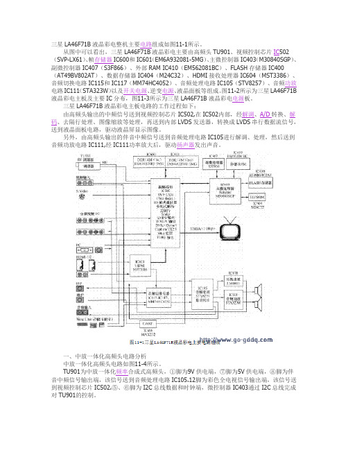
三星LA46F71B液晶彩电整机主要电路组成如图11-1所示。
从图中可以看出,三星LA46F71B液晶彩电主要由高频头TU901、视频控制芯片IC502(SVP-LX61)、帧存储器IC600和IC601(EM6A932081-5MG)、主微控制器IC403(M30840SGP)、副微控制器IC407(S3F866)、外部RAM IC410(EM562081BC)、FLASH存储器IC400(AT49BV802AT)、数据存储器IC404(M24C32)、HDMI接收处理器IC604(MST3386)、音频切换电路IC115和IC117(MM74HC4052)、音频处理电路IC105(STV8257)、音频功放电路IC111(STA323W)以及开关电源、逆变电源、液晶面板等组成。
图11-2所示为三星LA46F71B 液晶彩电主板及主要IC分布,图11-3所示为三星LA46F71B液晶彩电电源板。
三星LA46F71B液晶彩电主板电路的工作过程如下:由高频头输出的中频信号送到视频控制芯片IC502,在IC502内部,经解调、A/D转换、解码、去隔行处理、图像缩放等处理,再送到内部LVDS发送器,转换成LVDS串行数据流信号,送到液晶面板电路,驱动液晶屏显示图像。
另外,由高频头输出的伴音中频信号送到音频处理电路IC105进行解调、处理,然后送到音频功放电路IC111,经IC111功率放大后,驱动扬声器发出声音。
一、中放一体化高频头电路分析中放一体化高频头电路如图11-4所示。
TU901为中放一体化频率合成式高频头,①脚为9V供电端,⑦脚为5V供电端,⑧脚为伴音中频信号输出端,该信号送到音频处理电路IC105.12脚为彩色全电视信号输出端,该信号送到视频控制芯片IC502.⑤、⑥脚为I2C总线数据和时钟端,微控制器IC403通过I2C总线完成对TU901的控制。
二、输入接口电路分析三星LA46F71B液晶彩电的输入接口较多,下面仅对其中的YPbPr、VGA、HDMI接口电路进行分析。
三星 液晶显示器-电视LA22B450C4HXXZ LA22B450C4HXZK 维修手册

维 修薄膜液晶显示器电视目录LA22B450C4H1. 注意事项 2. 产品规格 3. 拆卸和重新组装 4. 故障排除5. 分解图和零件清单 6. 接线图参阅GSPN 维修手册(翻阅封底)获取更多信息。
液晶显示器-电视底板:N66C型号: LA22B450C4HXXZLA22B450C4HXZK手 册目录表1.注意事项........................................................................................................................................1-1 1-1安全注意事项...........................................................................................................................1-1 1-2维修注意事项...........................................................................................................................1-2 1-3静电敏感器件(ESD)注意事项..............................................................................................1-2 1-4安装注意事项...........................................................................................................................1-3 2.产品规格........................................................................................................................................2-1 2-1特点与规格..............................................................................................................................2-1 2-2与老型号的规格比较................................................................................................................2-4 2-3附件.........................................................................................................................................2-5 3.拆卸和重新组装..............................................................................................................................3-1 3-1拆卸和重新组装.....................................................................................................................3-1 4.故障排除........................................................................................................................................4-1 4-1故障排除 .............................................................................................................................4-1 4-2调整和调节............................................................................................................................4-13 4-3工厂模式调节.........................................................................................................................4-14 4-4设置旅馆选项数据 ............................................................................................................4-24 4-5白平衡-校准...........................................................................................................................4-28 4-6维修信息................................................................................................................................4-30 5.分解图和零件清单..........................................................................................................................5-1 5-1 LA22B450C4H分解图.............................................................................................................5-1 5-2 LA22B450C4H零件清单.........................................................................................................5-3 6.接线图............................................................................................................................................6-1 6-1接线图形..................................................................................................................................6-1 6-2接线图片..................................................................................................................................6-4 6-2连接器功能..............................................................................................................................6-4 6-3接线.........................................................................................................................................6-5GSPN (全球维修合作网络)国家网站北美拉丁美洲CIS 欧洲中国亚洲中东&非洲本维修手册归三星电子有限公司所有。
Hannstar HG171A液晶显示器图纸

Model Name:HG171A Model No:HSG1033 17” Color TFT LCD DisplayCopyrightCopyright © 2006 by HannStar Corporation. All rights reserved. No part of this publication may be reproduced, transmitted, transcribed, stored in a retrieval system, or translated into anylanguage or computer language, in any form or by any means, electronic, mechanical, magnetic, optical, chemical, manual or otherwise, without the prior written permission of HannStar Corporation.DisclaimerHannStar makes no representations or warranties, either expressed or implied, with respect to the contents hereof and specifically disclaims any warranty of merchantability or fitness for any particular purpose. Further, HannStar reserves the right to revise this publication and to make changes from time to time in the contents hereof without obligation of HannStar to notify any person of such revision or changes.TrademarksOpt quest is a registered trademark of HannStar Corporation.HannStar is a registered trademark of HannStar Corporation.All other trademarks used within this document are the property of their respective owners.Revision HistoryRevision SM Editing Date ECR Number Description of Changes TPV Model A00 Sep.-10-08 First Version Release T7RHM5D8AWHZNCA01 Dec.-02-08 Add new BOM in item 16 T7RHM5DBAWZ3NNTABLE OF CONTENTS1. Dimensions 42. Precautions and Safety Notice 63.Monitor Specification 74.LCD Monitor Description 85.Operation Instruction 96. Input/output Specification 147. Mechanical Instructions 188. Block Diagram 219.Schematic 2710.PCB Layout 3541 11.Maintainability12 DDC Instruction 4713. White-Balance, Luminance adjustment 5314.Monitor Exploded View 5515. BOM List 5616.Different Parts List (65)1. Dimensions 1.1 Front View1.2 Back View1.3 Side View1.4 Bottom View2. Precautions and Safety NoticesProper service and repair is important to the safe, reliable operation of all AOC Company Equipment. The service procedures recommended by AOC and described in this service manual are effective methods of performing service operations. Some of these service operations require the use of tools specially designed for the purpose. The special tools should be used when and as recommended.It is important to note that this manual contains various CAUTIONS and NOTICES which should be carefully read in order to minimize the risk of personal injury to service personnel. The possibility exists that improper service methods may damage the equipment. It is also important to understand that these CAUTIONS and NOTICES ARE NOT EXHAUSTIVE. AOC could not possibly know, evaluate and advise the service trade of all conceivable ways in which service might be done or of the possible hazardous consequences of each way. Consequently, AOC has not undertaken any such broad evaluation. Accordingly, a servicer who uses a service procedure or tool which is not recommended by AOC must first satisfy himself thoroughly that neither his safety nor the safe operation of the equipment will be jeopardized by the service method selected.Hereafter throughout this manual, AOC Company will be referred to as AOC.WARNINGUse of substitute replacement parts, which do not have the same, specified safety characteristics may create shock, fire, or other hazards.Under no circumstances should the original design be modified or altered without written permission from AOC. AOC assumes no liability, express or implied, arising out of any unauthorized modification of design.Servicer assumes all liability.FOR PRODUCTS CONTAINING LASER:DANGER-Invisible laser radiation when open AVOID DIRECT EXPOSURE TO BEAM.CAUTION-Use of controls or adjustments or performance of procedures other than those specified herein may result in hazardous radiation exposure.CAUTION -The use of optical instruments with this product will increase eye hazard.TO ENSURE THE CONTINUED RELIABILITY OF THIS PRODUCT, USE ONLY ORIGINAL MANUFACTURER'S REPLACEMENT PARTS, WHICH ARE LISTED WITH THEIR PART NUMBERS IN THE PARTS LIST SECTION OF THIS SERVICE MANUAL.Take care during handling the LCD module with backlight unit.-Must mount the module using mounting holes arranged in four corners.-Do not press on the panel, edge of the frame strongly or electric shock as this will result in damage to the screen.-Do not scratch or press on the panel with any sharp objects, such as pencil or pen as this may result in damage to the panel.-Protect the module from the ESD as it may damage the electronic circuit (C-MOS).-Make certain that treatment person’s body is grounded through wristband.-Do not leave the module in high temperature and in areas of high humidity for a long time.-Avoid contact with water as it may a short circuit within the module.‐If the surface of panel becomes dirty, please wipe it off with a soft material. (Cleaning with a dirty or rough cloth may damage3. Monitor Specifications4. LCD Monitor DescriptionAssembly DescriptionThe LCD MONITOR will contain a main board, a power board, and a key board which house the flat panel control logic, brightness control logic and DDC.The power board will provide AC to DC Inverter voltage to drive the backlight of panel and the main board chips each voltage.5. Operating Instructions5.1 General InstructionsPress the power button to turn the monitor on or off. The control buttons are located in the front of the monitor.By changing these settings, the picture can be adjusted to your personal preferences.-The power cord should be connected.-Connect the video cable from the monitor to the video card.-Press the power button to turn on the monitor, the power indicator will light up.5.2 Control ButtonsFRONT PANEL CONTROL• Power Button:Press this button to switch ON/OFF of monitor’s power.• Power Indicator:Green — Power On mode.Orange — Power Saving mode.• MENU / ENTER:1. Turn the OSD menu on/off or return to the previous menu2. Exit OSD menu when in volume OSD status.• Adjust < >:1. Activates the volume control when the OSD is OFF.2. Navigate through adjustment icons when OSD is ON or adjust a function when function is activated.• A Button:• The OSD menu is used as ¡§confirmation¡¨ function during start-up. 2. Press and hold this button more than 3 seconds will start 「Auto Adjust」function when using VGA input only. (The auto adjustment function is used to optimize the 「horizontal position」, 「vertical position」,「clock」,and 「phase」.)NOTES:• Do not install the monitor in a location near heat sources such as radiators or air dusts, or in a place subject to direct sunlight, or excessive dust or mechanical vibration or shock.• Save the original shipping box and packing materials, as they will come in handy if you ever have to ship your monitor. • For maximum protection, repackage your monitor as it was originally packed at the factory.• To keep the monitor looking new, periodically clean it with a soft cloth. Stubborn stains may be removed with a cloth lightly dampened with a mild detergent solution. Never use strong solvents such as thinner, benzene, or abrasive cleaners, since these will damage the cabinet. As a safety precaution, always unplug the monitor before cleaning it. • Function Key Lock:Press the 「<」, 「>」 and the 「Menu」buttons simultaneously to enable the Function Key Lock. When the Function Key Lock is enabled, only the Power button is active. Press the 「<, 「>」 and the 「Menu」buttons simultaneously again to unlock the function keys.08/09/09 5.3 Adjusting the Picture08/09/0908/09/096. Input/output Specification 6.1 Input Signal Connector6.2 Factory Preset Display Modes6.3 Panel SpecificationHannStar Display model HSD170MGW1-B00 is a color active matrix thin film transistor(TFT) liquid crystal display (LCD) that uses amorphous silicon TFT as a switching device. This model is composed of a TFT LCD panel, a driving circuit and a back light system. This TFT LCD has a 17.0 inch diagonally measured active display area withXGA resolution (900 vertical by 1440 horizontal pixel array) and can display up to 16.2M (6-bit+FRC)colors.6.3.1 Features_ 17.0 WXGA+ for Monitor application_ High Resolution: 1440*900_ 2-ch LVDS interface system_ LCD Timing Controller_ Wide Viewing Angle_ RoHS compliance6.3.2 Display Characteristics6.3.3 Electrical Characteristics1. TFT LCD Module2. Backlight Unit6.3.4 Optical CharacteristicsMeasuring Condition_ Measuring surrounding: dark room_ Lamp current IBL: 7.5±0.1mA, lamp freq. FL=50 KHz, Inverter: TDK TBD315NR-1 _ VDD=5.0V, fV=60Hz_ Ambient temperature: 25±2oC_ 30min. Warm-up time.7. Mechanical Instructions08/09/0908/09/091) MCU initialize.2) Is the EPROM blank?3) Program the EPROM by default values.4) Get the PWM value of brightness from EPROM.5) Is the power key pressed?6) Clear all global flags.7) Are the AUTO and SELECT keys pressed?8) Enter factory mode.9) Save the power key status into EPROM.Turn on the LED and set it to green color.Scalar initializes.10) In standby mode?11) Update the lifetime of back light.12) Check the analog port, are there any signals coming?13) Does the scalar send out an interrupt request?14) Wake up the scalar.15) Are there any signals coming from analog port?16) Display "No connection Check Signal Cable" message. And go into standby mode after the message disappear.17) Program the scalar to be able to show the coming mode.18) Process the OSD display.19) Read the keyboard. Is the power key pressed?8.2 Electrical Block Diagram 8.2.1 Main Board8.2.2 Power/Inverter Board8.3 Mechanical Block Diagram 8.3.1 Assembly Block8.3.1 Disassembly Block08/09/09 9. Schematic9.1 Main BoardTSUM16FWR SCHEMATICXGA/SXGA LVDS OUTPUT08/09/095555555HG171A F B 47Monday , July 21, 2008715G2904-1D <称爹>02.InputG2904-1D-2-X -4-080728OEM MODEL Size Rev DateSheetofTPV MODEL PCB NAME 称爹T P V ( Top Victory Electronics Co . , Ltd. )Key Component絬 隔 瓜 絪 腹5555HG171A F B 77Monday , July 21, 2008715G2904-1D <称爹>05.PowerG2904-1D-2-X -4-080728OEM MODEL Size Rev DateSheetofTPV MODEL PCB NAME 称爹T P V ( Top Victory Electronics Co . , Ltd. )Key Component絬 隔 瓜 絪 腹4, 508/09/095HG171A F A 67Monday , July 21, 2008715G2904-1D <称爹>04.OutputG2904-1D-2-X-4-080728OEM MODEL Size Rev DateSheetofTPV MODEL PCB NAME 称爹T P V ( Top Victory Electronics Co . , Ltd. )Key Component絬 隔 瓜 絪 腹5PPWR_ON#508/09/09 9.2 Power Board08/09/0908/09/0908/09/09 10. PCB Layout10.1 Main Board08/09/0908/09/0908/09/0910.2 Power Board08/09/0908/09/09 10.3 key board11. Maintainability11.1 Equipments and Tools Requirement1. Voltmeter.2. Oscilloscope.3. Pattern Generator.4. DDC Tool with Compatible Computer.5. Alignment Tool.6. LCD Color Analyzer.7. Service Manual.8. User Manual.11.2 Trouble Shooting11.2.1 Main BoardNo powerNo picture (LED orange)08/09/09 White screen08/09/09 11.2.2 Power Board1) No power08/09/09 2.) No Backlight11.2.3 Key Board12. DDC InstructionGeneralDDC Data Re-programmingIn case the main EEPROM with Software DDC which store all factory settings were replaced because a defect, repaired monitor’ the serial numbers have to be re-programmed.It is advised to re- soldered the main EEPROM with Software DDC from the old board onto the new board if circuit board have been replaced, in this case the DDC data does not need to be re-programmed.Additional information about DDC (Display Data Channel) may be obtained from Video Electronics Standards Association (VESA). Extended Display Identification Data (EDID) information may be also obtained from VESA. 1. An i486 (or above) personal computer or compatible. 2. Microsoft operation system Windows 95/98/2000/XP . 3. “ PORT95NT.exe, WinDDC_ setup” program. 4. Software OSD SN Alignment kits The kit contents: a. OSD SN BOARD x1b.Printer cablex1c. VGA cable x1d. Digital cable x1e. 12V DC power source1. Install the “PORT95NT.EXE”, and restart the computer.2. Install the “WinDDC_ setup”3. Connect the DDC board as follow: (Take philips 190B8 for example)Note: Pin5 of the VGA cable which connects to the monitor should be cut off.08/09/09 4. Take analog DDC write for example, as followa. Double-click ,appear as follow Figs:b. Click .c. Key 14 numbers in the Serial Number blank, then click “OK”. Now analog DDC Write completes, as follow.Note: The way of digital DDC write is the same as analog DDC write.HG171A EDID128 bytes EDID Data (Hex):00 01 02 03 04 05 06 07 08 09 10 11 12 13 14 150: 00 FF FF FF FF FF FF 00 22 64 D1 1B sn sn sn sn16: ww yy 01 03 0A 25 17 78 EA B6 90 A6 54 51 91 2532: 17 50 54 BF EF 80 81 80 81 C0 81 40 71 4F 61 4648: 90 4F 95 0F 01 01 9A 29 A0 D0 51 84 22 30 50 9864: 36 00 72 E6 10 00 00 1E 00 00 00 FD 00 sn sn sn80: sn sn sn sn sn sn sn sn sn sn 00 00 00 FF 00 3296: 33 31 31 32 33 31 32 33 31 32 33 33 00 00 00 FC112: 00 48 61 6E 6E 73 2E 47 20 48 47 31 37 31 00 D2。
SAMSUNG 4.3inch 480X272RGB TFT-LCD
Aug. 20. 2007
Rev. No.
000
Page
Summary
Rev.000 was first issues.
Doc . No LTE430WQ-F0C Rev.No
000
Page
2 /34
Approval
Contents
General Description 1. Absolute Maximum Ratings
----------------------------- (22) -------------------------- (27) -------------------------- (28) -------------------------- (29) -------------------------- (30) -------------------------- (31)
Doc . No LTE430WQ-F0C Rev.No
000
Page
6 /34
Approval
1.2 Electrical Absolute Ratings (1) TFT-LCD Module
(Ta = 25 ± 2°C, VSS=GND=0)
Item Digital power supply
------------------------- (14)
5. Block Diagram
-------------------------- (17)
5.1 TFT-LCD Module(Interface System Structure) with Back Light Unit 5.2 Touch Screen Panel 5.3 Back-light Unit
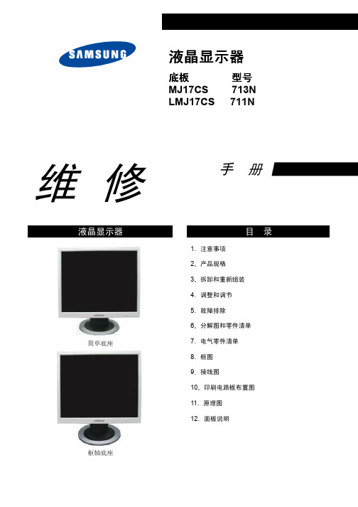
17寸三星液晶显示器维修
3-2 重新组装
重新组装步骤与拆卸步骤相反
3-2
4 调整和调节
维修手册本章说明如何使用 RS232 JIG 该功能为更换 AD 板和程序存储器 IC110 所需
4-1 所需的设备
以下设备为调整显示器所需 • 装有Windows 95 Windows 98或Windows NT的计算机 • MTI-2031 DDC管理工具
1. 亮度和对比度值应变为零 2. 在 5 秒内 按 确定/来源 键 3. 维修功能 OSD 将显示 *如果您想取消维修功能 OSD 则必须断电
显示屏信息
图 2. 维修功能 OSD 举例
软件版本 检验和
维修功能 OSD 是基于 29 列 12 排的网格 维修功能 OSD 包含显示屏信息 软件版本和 MICOM 检验和
4-6-2 如何控制维修功能 OSD
1. 在 OSD 上选择了显示屏时 在您按下右键时 底色会改变成蓝色 从 显示屏 到 上灯 下灯
图 3.
4-2
4-6-3 如何控制维修功能 OSD
*在更换显示屏或灯后 必须重设维修功能 OSD *更换显示屏的情况 在更换显示屏后 在 5 秒内按菜单键 然后 显示屏频道数升高一级且显示屏时间信息被重设为零 同时 其它信息被重设为零 上/下灯 显示屏循环
4 调整和调节
图 4.
4-6-4 如何控制维修功能 OSD
*在更换上灯或下灯的情况下 在更换上灯或下灯后 1. 选择上灯或下灯 2. 在 5 秒内按菜单键 然后 频道数和时间会被重设为零 仅限于选定项
图5 6
4-3
4 调整和调节
备忘录
4-4
故障排除
5 故障排除
注意
1. 在进行故障排除之前 按如下方式设置 PC 显示器 分辨率 1024 768 水平频率 61 kHz 垂直频率 75 Hz
三星700S显示器维修

三星700S显示器一、三星700S显示器的整机结构三星700S显示器是比较流行的一种多频显示器,它具有节约功能。
三星700S显示器的电路结构比较紧凑,电路支架比较牢固,拆去后盖可以看到它的主要部件,如图1~图3所示。
图1 三星700S显示器的整机构成图2 三星700S显示器的后视图图3 三星700S显示器的侧视图1.三星700S显示器的电路图4是三星700S显示器的电路方框图,从图可见,它主要是由视频信号处理电路,系统控制电路,行/场扫描电路,电源电路等部分构成的。
图4 三星700S显示器电路方框图电脑主机中显卡的输出信号送入显示器,其中R、G、B图像信号送入视频电路,先经IC101(KA2140B)视频前置放大器,对R、G、B信号进行预放,然后再送到视频输出电路IC102(LM2405T)进行主放大,经放大后去驱动显像管三个阴极。
IC104(LSC 4350)为屏上显示电路为IC101提供字符显示信号,IC103(KA324)对R、G、B信号进行截止控制。
电脑显卡输出的行/场同步信号直接送到微处理器IC201,IC201对行/场同步信号(H-SYNC、V-SYNC)进行处理,然后输出行/场同步信号到扫描信号产生电路IC401UPC 188作为扫描基准信号。
微处理器接收面板的人工指令信号,同时也为IC401输出水平和垂直扫描的幅度、位置和枕形校正线性等控制信号。
扫描电路中IC401是扫描信号产生电路,它为场扫描、行扫描等电路输出脉冲信号。
同时还输出行扫描电源驱动信号和高压激励信号,以及场消隐信号。
行输出级晶体管为Q406,行输出级变压器为T402。
高压电路是独立的电路,高压输出晶体管Q508为高压输出变压器T501提供驱动脉冲,高压输出变压器T501为显像管提供阴极高压、聚焦极电压、加速极电压、以及辅助电压。
开关电源主要是输出+70V、+45V、+13V、-12V、+7V等电压。
二、行扫描电路1.扫描信号产生电路图5是三星700S显示器的扫描信号产生电路,该系列显示器机采用以μPC1883为核心的扫描信号处理电路。
三星等离子V3屏电源电路原理与维修资料

海信使用的三星V3 屏等离子电视,社会拥有量很大。
随着时间的推移,该系列产品正逐渐进入维修期。
等离子彩电上的主板和AV 板由于大家经常接触,都比较熟悉,这里不作介绍。
由于等离子电源是和屏电路一起由三星公司成套提供,维修配件和维修资料都相对匮乏,给维修人员地检修带来了相当大的难度。
由于各厂家换板的周期长,并且还不一定能申领到备件,这就导致了我们必须要对电源进行元器件的维修。
下面主要介绍一下,该系列机型用的三星V3 屏等离子电源的工作原理与常见故障的检修。
整机电源电压产生流程方框图:图1 等离子V3 屏电源方框图上面是根据检修经验所得而绘制成的电压产生方框图,从上图可以看出,每一个电源电压的产生,都是需要有前提条件的。
也就是说,后级电压的产生,都是建立在前级工作正常的条件下的。
如果前级电压不能正常产生,后级的电压肯定不正常。
大家只要明白了某一路电压的产生条件,就会准确找到相应的故障部位。
一、进线抗干扰电路及VSB(待机5V)电压形成电路:AC 220V 经插座CN8001 进入后,经F8001 进入SA8001、R8005、C8004、C8096、L8002、RA8001、R8004、C8003、C8008、C8006 组成的过压保护电路和前级进线抗干扰电路。
滤除干扰信号后的交流电压分成两路,一路送到由L8003 等元器件组成的下一级抗干扰电路,如图2 所示:图2 二级进线抗干扰电路另一路经F8002、D8007、C8017 整流滤波后,形成不稳定的300V 直流电压。
该电压经过T8001 的#2 脚~#1 脚绕组加到IC8003(TOP223PN)的#5 脚。
TOP223PN 的内部方框图如图3 所示,5VSB 形成电路如图4 所示:图3 TOP223P 内部方框图图4 5VSB 电压形成电路IC8003 进入工作状态,从T8001 的次级绕组整流滤波(D8014、C8018)后,形成VSB(+5V)电压,给主板CPU供电。
三星显示器说明书
请把监视器的直流电源适配器插到监视器背后的电源端口上。
将信号线连接至显示器背面的 15 针 D-sub 端口。
Kensington 防盗锁是一种用于防止系统在公共场所使用时被盗的实用 设备。(此锁必须另行购买。) 关于如何使用防盗锁的信息,请联系经销商。
关于电缆连接的进一步信息请看连接你的显示器。
连接显示器
电源按钮 [ ] 电源指示灯
运行 MagicBright 功能,然后按下 [ ] 键 5 秒钟,转换到 MagicBright ECO 功能。 MagicBright ECO功能运行状态下,按下 [ ] 键5秒钟,转换到 MagicBright 功能。 >>点击这里以观看动画剪辑。
当屏幕上没有 OSD 时,按下按钮可以调节亮度。 这些按钮让你选择突出并调整菜单里的一些项目。 用于选择 OSD 菜单。
请不要把显示器的荧屏朝地面放置。 z 液晶显示器(TFT-LCD)的表面可能受到损伤。
安装墙壁支架必须由有资格的专业人员进行。 z 没有资格的人员进行安装可能会导致人身伤害。 z 切记只能使用用户手册中规定的安装设备。
在安装本产品时,出于保持通风之目的,请确保将它与墙壁隔开一段距离(大 于 10 厘米/4 英寸)。
不要只是拉动电线或信号电缆来使显示器左右移动。 z 这样由于会损坏电线而造成破坏、电击或起火。
不要盖住显示器机壳上的通风口。 z 通风不好可能会使工作停止甚至会起火。
不要在显示器上放置任何重的东西。 z 这有可能造成电击或起火。
不要让本产品接近易燃化学喷雾或易燃物品。 z 这有可能造成爆炸或火灾。
其他
不要打开护盖(或后盖)。 z 这会造成电击或起火。 z 要让合格的维修人员来维修。
如果你的显示器工作不正常—特别是当有任何异常的声音或气味从显示器里出来的 话—要立即拔下插头,并与一个授权的经销商或服务部门联系。
