维卡软化点D1525
塑料软化点(维卡)的测定
1.试样与预处理 (1)试样厚度为6mm,宽和长各为20mm。 (2)试样的支撑面和侧面应平行,表面平整光滑、
无气泡、无锯齿痕迹、凹痕或飞边等缺陷。 (3)每组试样为2个。 (4)试样的预处理可按产品标准规定进行,产品
标准若无规定时,可直接进行测定。
2.实验设备
本实验采用RHV-300微机控制式热变形维卡软化 点温度测定仪来测量塑料软化点温度。此试验仪 由机械部分和电气部分组成:机械部分主要完成 承载液压油,装夹试样,对试样施加固定载荷以 及对液压油的搅拌等。电气部分完成对液压油的 加热和控温,试验数据的采集和对整个试验过程 的控制。
塑料软化点(维卡)的测定
一、实验目的 测定热塑性材料的软化点(维卡)的温度,并掌握
其试验方法。
二、实验简述(实验原理)
本实验是在特定的液体传热介质中、一定的升温 速度下,施加特定的负载后,横截面积为1mm2 的平头针刺入塑料试样中1mm时的温度。
各种塑料的高温作用下,所发生的作用是不同的, 温度对塑料的各方面的性质影响较大,为了测定 塑料温度随温度上升而发生变形来确定塑料使用 的范围,规定了许多的测试方法,最常用的是 “马丁耐热试验方法”、“维卡软化点测试方 法”。这些方法测试的温度,仅仅是在该方法规 定的载荷大小、施力方式、升温速度下到达规定 的变形量时的温度,而不是这种材料的使用温度 上限。
四、实验过程
(1)将被测试样放在支架上,其中心位置应在顶针 头下面,载荷杆与试样垂直,经机械加工的试样, 加工面应紧贴支架底座。
(2)将装好试样的支架小心浸入浴槽内,试样位于 液面35mm以下,起始温度应至少低于该材料软 化点(维卡)50℃。
(3)试样装好后,加上负载,打开搅拌器搅拌 5min后调节变形测量装置,使之为零。
POM性能

什么叫“夺钢”共聚甲醛树脂“夺钢)(DURACON)“夺钢”被认为最能信赖的工程塑料,而为各方面所注目。
工程塑料就是“在结构材料及机能配件的领城里寻找主要用途的塑料”。
因此,用做工业材料时,即或生产严酷的温度、负荷、环境条件下放置长时间,其物理性必须要保持信赖性。
由化学的观点来说,“夺钢”是称为“缩醛共聚物”的结晶性热塑树脂,以甲醛三量体的三哑烷(trioxane)为主要原料,而在聚氧化甲烯主锁[--C—0]中含有[--C-C---结合]的共聚物。
共聚用单体<IMG height=48 alt="z-1.jpg (12037 bytes)" src="mk:@MSITStore:C:\Documents%20and%20Settings\ym\My%20Documents\pom.chm::/z-1. jpg" width=350>“夺钢”由于含有做为共聚物而引进的[--C—C---结合],因而即使由于热或是其他原因而开始分解,也由于在聚氧化甲烯主锁[---O---CH2--]以防止以后的分解聚合。
因此,“夺钢”较之缩醛均聚物不论在化学性上或对于热均稳定性上均更卓越。
如此,“夺钢”是具备着共聚物卓越的稳定性和氧化甲烯的卓越机械强度的工程塑料,而在原有的塑料所预料不到的领域里发挥其优越特性,正在开拓着广泛的用途。
,“夺钢”的特点∙如将“夺钢”的特点与其他塑料比较,则可举出如下各点。
∙保持平衡的机械性质∙塑料中能受最高的耐疲劳性∙在广泛环境下卓越的耐蠕动变性∙卓越的磨擦、损耗特性∙卓越的耐有机药品性、耐碱性∙卓越的耐热性.“夺钢”胶粒的种类“夺钢”胶粒的种类可大别为M90系和M25系。
M90系较M25系,熔融粘度为低,一般地适于压射成形,M25系则适于挤压成形。
M90系、M25系均有添加润滑剂者与不添加者。
《第1表》示以胶粒种类和其使用区分的一般原则。
意大利CEAST公司热变形维卡软化点仪

H D T3&6VI C A TThese instruments are made incompliance with CE healthand safety requirementsD E S I GN A ND P R OD U C TI O N OFI N S T RU M E NT S A ND A P PA R A T USF O R QU A L I TY C O NT R O LO N MA T E R IA L S“HDT” test means: determination of temperature of deflection under load Field of applicationThe test determines the temperature at which a specified deflection occurs when a standard test specimen is subjected to a bending stress, to produce one of the nominal surface stresses according to international standards. This test is very important for both quality control and research into plastics because it determines the heat resistance characteristics of materials, and is indispensable to define precisely the thermal behaviour of the polymers. The values obtained are indicative of the heat resistance characteristics of materials, even if not directly applicable for design purposes.MethodThe specimen, in the form of a rectangular bar of dimensions complying with the chosen standard, is tested as a simple beam with a load applied at midspan to produce amaximum, nominal surface stress according to the chosen standard. The test assembly, with the loaded specimen, is then immersed in a heat-transfer medium, equipped with a system capable of increasing the temperature linearly at a uniform rate (generally 2 °C/min). The temperature, when the specimen reaches a specified deflection is recorded.This value is indicated as the Temperature of Deflection Under Load, in degrees Celsius, of the material under test.“VICAT” test means: determination of the VICAT softening temperature Field of applicationThe test determines the temperature at which a standard indenter penetrates 1 mm into the surface of a test specimen under load. It is used to establish the differences between many types of thermoplastic materials with regard to their softening properties.MethodAn indenting tip of 1 mm 2circular cross sectional area is placed on the specimen and is loaded with a constant force (10 N or 50 N depending on the standard method used).The test assembly, with the loaded specimen, is immersed in a heat-transfer medium equipped with a system capable of increasing the temperature linearly at a uniform rate (generally, 50°C/hour or 120°C/hour).The temperature, when the needle has penetrated 1 mm into the specimen, is recorded.This temperature, expressed in °C, is indicated as the VICAT Softening Temperature of the material under load.Additional testsUsing this instrument it is possible to perform flexural creep tests and to determine the elastic modulus of materials and to measure the thermal dilatation.The elastic modulus can be evaluated at different temperatureso that it is possible to study the trend of elastic modulus of a material as a function of temperature.StandardsDesigned and built to meet the following standards:“HDT” TESTISO 75, ASTM D 648, DIN 53461, BSI 2782, Method 121 C,NT T 51-005, UNE 53075and others equivalent.“VICAT” TESTISO 306, ASTM D 1525, DIN 53460, BSI 2782, Method 120 C,NT T 51-021, UNE 53118and others equivalent.HDT test stationVICAT test stationInstrument FeaturesCompact instrument for HDT, VICAT, and also CREEP testing with automatic control of entire test cycle complete with command keyboard, built in parameters and results display and ability to continuously monitor bothtemperature and deflection/penetration. Cooling cycle is automatic at test end. Nitrogen blanket diffusor for oil bath safety at high temperature with external electro valve and connection.Ability to print out full quality control report including graph on A4 printer without need for a PC. Possibility to work with Windows based software without need for any separate interface.HDT/VICAT keyboard and displayHDT 3 VICAT - code 6911.000 Technical data 6911.000 6921.000Number of stations 36Test capabilities:Hdt, Vicats s Hdt and Vicat results at the same time s Creep, Thermal dilatation, Elastic modulus ❏❏Thermal distribution °C (100 to 250°C)±0.2 to ±0.3±0.2 to ±0.3Thermal stability °C (300°C)±0.5±0.5Temperature range °C20 to 30020 to 300Temperature preset accuracy °C ±0.2±0.2Temperature resolution °C0.10.1Temperature ramps selectable via keyboard:• 120°C/h ±10°C (12 ±1°C/6 min)s s • 50°C/h ±5°C (5 ±0.5°C/6 min)s s • Operator may select any other rate between 50 and 120°C/h s s Temperature measurement:• Each station - PT 100 thermoresistance calibrated 36• bath control - PT 100 thermoresistance calibrated 11Deflection/penetration measurement:• LVDT accuracy for each station (mm) calibrated0.0010.001Independent automatic compensation via dedicated software for thermalexpansion of each work station. Calibration data can be printed for each station s s Built-in microprocessor to automatically carry out instrument processing with PID heating controlss6911.000 6921.000 Electronic control unit with alphanumeric keyboard:• Liquid Crystal Display 128 x 240 points s s • CPU board s s • Amplifier and signal board independent s s • DC power supply s s Data display (graphs, parameters)s s Automatic deflection/penetration transducer zeroing s s Automatic cooling system at test end s s Cooling time from 200 to 50°C (min)2020 Autocheck during test execution s s Nitrogen diffuser and electrovalve, to create a layer of Nitrogen to prevent theheat transfer medium from degrading at high temperatures s s Nitrogen bottle and connections❏❏Oil pump s sOil level depstick s s Safety thermostat s s Heat tranfer fluid (kg)1520 Binary mass system (one set for each station) consisting of a set of 13 masses tocover all HDT and VICAT tests using any mass from 67 to 5140 g in minimum❍❍steps of 1 gHDT testHDT capability to test sample in flatwise or edgewise position with 64 or100 mm free span according to international standards s s Automatic calculation and list of masses to apply to reach defined stressaccording to standards 0.450 - 0.455 - 0.500 - 1.80 - 1.82 - 5.00 - 8.00 MPa s s HDT testing heads complete with traceable certificates (one for each station)❍❍HDT head positioning tool for HDT head positioning❏❏VICAT testVICAT masses (one set for each station) for a total of 10N and 50N. For VICATtests only. These masses are ready included in the binary mass system, which❏❏allows to perform HDT and VICAT testsVICAT testing heads complete with traceable certificates (one for each station)❍❍Data acquisitionParallel port for full report print-out by printer s sRS232 serial port for connection to PC in conjunction with WinHDT6 software s s Software in Windows 95, 98 and NT environment❏❏Data acquisition interface built into the basic instrument s s Personal computer❏❏Graphic printer 80 columns, parallel interface and cable❏❏s Included ❏Optional ❍Necessary to perform testsCeast Software Available with Hdt Vicat Family VisualTHERM code 0710.500 - Base ModuleThe program works in Windows environment and can run on any PC.VisualTHERM enables the user to perform the following operations and to obtain the following results depending on which instrument the software has been configured for: Parameter Management•Possibilty to select, for each station, the test type (HDT or VICAT)•Presetting of End Test condition: End Displacement (deflection or penetration, even at different values from the standard ones), End Temperature or both•Saving and reloading of test parameters•Calculation and display of the load weight needed to apply the required stress on the specimensProcess Management•Transmission of the selected set of parameters to the instrument•Management of the asynchronous utility commands from the PC (Basket up, Basket down,… )•Synoptic panel management: instrument status and read out values•Station calibration guide with graphic panel•Test Management is done with guided messages and dedicated buttons•Test execution with data acquisition from apparatus, real-time graph managementResult Processing•Saving of all the data acquired by the instrument (raw data)•Measuring Units selection: SI, BU or other main measuring systems•Visualization of graph with overlay curves•Visualization of graph with single curve: possibility to select the station displayed in the graph•Choice of the kind of graphics: Deflection or Penetration curves Vs Time or Temperature and Shifted curves •Visualization of table in which all data of each active station are displayed•Visualization of test general and statistical data •Visualization of data of single station•Graphic point management: display ofMeasurement/Temperature/Time of the point indicated •Possibility to modify comment after Test•It is possible to export the selected parameters and the selected data in TXT format file•It is possible to export the test graphs (even if elaborated by the operator) in BMP format fileStandard Report•Printout of parameters, graph and data of the Test for the selected stations.•It is possible to change the customer logoParameters ManagementPresentation of Results Real Time Graph ManagementHDT 6 VICAT - code 6921.000Technical Characteristics 6911.0006921.000Total bath capacity [l]1830Overall dimensions (L x D x H) [mm 3]1100 x 510 x 6001420 x 510 x 600Weight [kg]110130Supply 230 V - 50/60 Hz - Singlephase (110 V on request)Power [W]30004000Paintfuchsia RAL 4006 - gray RAL 7035Additional CEAST software modules:OPERATOR Module - code 0710.501Password-based operator access level management to assure data security and also to simplify the operating procedure of the non-expert operator . 3 levels available: Supervisor ,Manager , OperatorMULTI Module - code 0710.503.nConcurrent management of n instruments at the same time for all enabled functions, including the complete handling of the process: parameters selection, test execution, real-time synoptic and data acquisitionTRANSFER Module - code 0710.502Possibility to manage and transfer data in Excel and Text file with format templates managementCREEP Module - code 0710.443CREEP test management to have an idea of flexural creep behaviour of materials at different temperaturesELASTIC MODULUS Module - code 0710.444To measure Flexural Elastic Module at different temperatures THERMAL DILATATION Module - code 0710.445To investigate the thermal dilatation which the materials might show if kept in temperatureExample of Multi PresentationA P 911-04 0303- V A L F R È - P R I N T E D I N I T A L YCEAST S.p.A.• Via Airauda 12 - 10044 Pianezza - TO - Italy。
ABS树脂加纤物性参考表

2010GF性能Properties 测试标准Standard测试条件Condition单位Unit数值Value 物理性能Physical Properties密度Specific Gravity ASTM D79223℃g/cm3 1.1洛氏硬度Rockwell Hardness ASTM D78523℃102~113成型收缩Mold Shrinkage,Flow ASTM D955Cold mold, 48 hrs%0.2~0.4吸水率Moisture Absorption ASTM D57023 °C; 50 % RH%0.3机械性能Mechanical Properties拉伸强度Tensile Strength ASTM D63850mm/min Mpa46~60断裂伸长率Elongation at Break ASTM D63850mm/min%2~5弯曲强度Flexural Strength ASTM D7903mm/min Mpa75.8~90弯曲模量Flexural Modulus ASTM D7903mm/min Mpa3000~4000悬臂梁冲击强度Izod Impact, Notched ASTM D256J/m53~90热性能Thermal Properties维卡软化点Vicat Softening Temperature ASTM D1525℃110熔融指数MFR ASTM D1238220℃/10kg g/10min30热变形温度HDT ASTM D648 1.8 Mpa℃90~100阻燃性能Flammability UL94 1.6 mm HBASIA INT’L ENTERPRISE ( HONG KONG ) LIMITED深圳市亞太興實業有限公司廣東省深圳市寶安九區廣場大廈14樓 Tel:86-755-29993288 Fax:86-755-29991288High Performance SAN+10~30%GF HB Polyetherimide Materials该表为本产品测试的典型值,不作为产品验收的标准。
维卡常见问题及问答

维卡软化温度测试常见问题解答1. 什么是维卡软化温度?它反映材料的什么性质?答:维卡软化温度是指,当匀速升温时,某一负荷条件下,横截面积为1 mm2的标准压针刺入热塑性塑料1mm深时的温度。
该温度反映了材料在升温装置中使用时期望的软化点,即材料在受热和受力的情况下的耐热性能。
2.维卡软化温度测试的原理与本质是什么?答:材料的软化实质上是玻璃化转变。
低于玻璃化转变点时材料为刚性状态,高于玻璃化转变点时,材料为软化状态,可由横截面积为1 mm2的标准压针刺入热塑性塑料1mm深来指定相同的软化程度,这样就方便不同的材料按照相同的测试条件进行比较。
3.哪些材料需要测试维卡软化温度?答:维卡软化温度适用于测试热塑性硬质或半硬质塑料,材料在使用过程中受力和受热的情况下需要测试维卡软化温度或者热变形温度。
受力面积小如针尖的测维卡软化温度,受力面积较大的测热变形温度。
4.哪些材料不适用于维卡软化温度测试?答:由于维卡软化温度测试仅适用于热塑性硬质或半硬质塑料,所以热固性的材料或者软质材料就不适用于此方法测试。
判断材料是否是软质可凭手感,或者直接将试样放在压针下并加载砝码,过段时间压针如果直接刺入样品内部则不适宜用此方法检测。
5.维卡软化温度测试常用的测试标准有哪些?答:ISO 306:2004热塑性塑料维卡软化温度(VST)的测定,GB/T 1633-2000 热塑性塑料维卡软化温度(VST)的测定,ASTM D1525-2009塑料维卡软化温度的标准测试方法。
6.ISO 306:2004、GB/T 1633-2000以及ASTM D1525-2009,这三个标准有何不同?答:ISO 306:2004与GB/T 1633-2000是一致的,但与ASTM D1525-2009有两点区别。
一是ASTM D1525增加了可用流体粉末等作为传热介质的规定;二是两者加载负载时间不同,ISO306:2004是先将样品放入介质,5分钟后加载砝码再将千分表清零,ASTM D1525-2009则是先将样品放入介质,然后加载砝码,再过5分钟后将千分表的读数清零。
PolyCarbonate(PC)简介

•维卡软化点(VST, ASTM D 1525) 维卡软化点一般比热变形温度高,并且对树脂的实质软化点的测试上非常有用,因 为不受试样注塑条件的影响。 PC 树脂的维卡软化点随熔融指数增加也能维持较高 的维卡软化点。 ( 熔融指数 4 :151℃;熔融指数 22: 147℃) 另外, 因PC树脂的收缩率(0.005-0.007mm/mm)和线性热膨胀系数低,所以可用于高 温环境下要求耐热性能的产品。
PC原材料的用途及应用范围
应用范围 电器和电子 产品 一般机械 举例 通讯(手机, 传呼机)零部件, 家电(VTR, 音响)零部件, 电子 (电脑, 终端设备, 连接器)零部件, 照明(信号灯)零部件 电动工具零部件, 泵叶轮, 螺栓, 螺丝
精密办公 设备
汽车配件 医疗机械 安全设备
相机配件, 表的零部件, 现金出纳机零部件, 复印机零部件
大前灯镜头, 仪表板 眼药水容器 头盔, 防尘眼镜
PC的冲击强度与缺口直径的关系
缺口直径的大小对PC的冲击强度影响很大。 上图为不同熔融指数所对应的冲击强度与缺口直径的关系。当缺口直径为10-mil时, 随熔融指数增加冲击强度没有大幅度的下降情况;当缺口直径为 5-mil时,因应力过 于集中,当熔融指数高于12时,冲击强度有急速下降的情况。
PC的应力-应变(S-S) 曲线(@23℃)
PC的熔融指数与螺旋流长度的关系
如图所示在相同的加工温度及相同的挤出压力条件下,可以看得出熔融指数为22的树脂 比熔融指数为15的树脂在流动距离上比较长.因此螺旋流试验对树脂的实质流动性比较 上非常有用.
PC的伊佐德式冲击强度与温度关系
如上图所示温度和流动性对冲击强度的影响。当温度上升时,分子的运动会活跃起来, 因此树脂的柔软性和冲击强度也跟着增加。反之,当温度低于零摄氏度以下时,冲击 强度有急剧下降的倾向,特别是熔融指数越高这种倾向越明显,因此在选择低温条件 下使用的材料时得考虑上述倾向问题。
PP-R增韧剂功能及应用
PP-R增韧剂功能及应用PP-R增韧剂功能及应用无规共聚:无规共聚所得的产物称为无规共聚物。
由两种(或两种以上)单体单元规则排列连接形成。
两种单体羊元序列长度分布各自均无规分布。
组成不均一的混合物。
无规共聚物都具有很好的性能。
抗蠕变性:材料在恒载下(外界载荷不变)的情况下,变形程度随时间增加的现象,蠕变不仅出现在塑料(高分子材料中),还出现在金属材料中.蠕变反映的是材料在载荷下的流变性质,即受载后的流动;对于塑料和其他高分子材料而言反映了其内在的粘弹性.蠕变性还反映了塑料在温度变化下,自身的稳定情况温度梯度:是自然界中气温、水温或土壤温度随陆地高度或水域及土壤深度变化而出现的阶梯式递增或递减的现象。
通常把温度增加的方向作为正方向。
结晶取向:聚合物以结晶态存在,取向为化学结构的取向排布温度是塑料结晶过程中最敏感的因素,温度相差1℃,则结晶的速度可相差几倍。
塑料熔体从Tm以上冷却到Tg以下,这一过程的速度称为冷却速度,它是晶核存在或生长的决定性条件。
PP-R存在的问题1、PPR材料天然缺陷:低温(0℃以下)韧性不好即会产生低温脆裂,特别是在北方低温水管会脆裂,施工的过程中还要轻拿轻放。
2、产生一定的废品率(20-40%):管材在加工过程中管拉出来后会冷却,管材冷却即为结晶的过程,要求结晶取向、结晶粒越多越小,晶粒之间有许多连接点,表现为良好的韧性、抗压强度高且抗蠕变开裂,要求管材加工企业需要有严格的加工条件,精确的施工工艺控制和冷却定型温度梯度场值(受到环境、天气、温度、湿度、工艺等因素的影响)。
这对于绝大多数企业来说是一个难以逾越的挑战。
产生的废品需要破碎回炉。
3、PPR冷水管目前主要采用POE或EPDM等软性材料进行增韧处理,)这种增韧方法除了导致成本上升,另使管材使用寿命大幅下降(PPR 管材设计寿命为50年,此种增韧方式降到5年)这些增韧剂无法用在热水管,耐压强度不过关,因为这些增韧剂热变形温度在50℃,PPR热水管要求长期使用温度为70℃,短期使用温度为90℃。
维卡软化点测试

(5)检查下仪器显示,打开加热开关。 (6)观察视频显示记录实验数据。 (7)当达到预设的变形量或温度,实验自动停止后,打开
冷却水源进行冷却。然后向上移动位移传感器托架,将砝 码移开,升起试样支架,将试样取出。 (8)实验完毕后,依次关闭主机、工控机、打印机、电脑 电源。
7化点 英 文 名 称 :Vicat softening temperature(VST) 维卡软化温度:当匀速升温时,某一负荷条件下,截面1 m ㎡的标准压针刺入热塑性塑料1mm深时的温度。该温度反映 了当一种材料在升温装置中使用时期望的软化点。 测 试 标 准 :ASTM D1525, ISO 306, GB/T 1633 试 验 数 据 :维卡软化点试验测定了针头压入试样1mm时的 温度
3
实验仪器及试样
微机控制热变形维卡 软化点温度试验机
4
VST实验示意图
负载杆针头长3—5mm,横截面积为 (1.000+0.015)平方毫米,压针 头平端与负载杆成直角,不允许带 毛刺等缺陷。
加热浴槽选择对试样无影响的传热 介质,如硅油,变压器油、液体石 蜡等,室温粘度较低。
加热器等速升温速率为: (5±0.5)℃/6min 或(12±0.5)℃/6min。
1
维卡软化点测定的实验原理
聚合物的耐热性能,通常是指它在温度 升高时保持其物理机械性质的能力。聚合 物材料的耐热温度是指在一定负荷下,其 到达某一规定形变值时的温度。发生形变 时的温度通常称为塑料的软化点Ts 。
2
热塑性塑料维卡软化温度(VST)实验方法
依据现行的标准:GB/T1633-2000
试样承受的静负载G=W+R,其中 W—法码重量(克) R—压针及负 载杆的重量(克)
HDT和维卡软化点

• 测试步骤: 测试步骤:
• 1)将符合要求的试样按规定进行状态调节; • 2)测量试样中点附近处的高度(h)和宽度(b),精确到 0.05mm,确定试样的变形量; • 试样应变量与试样的高度及中点变形量成正比关系。
6 hy ε = l
• 3)计算砝码质量,使试样承载后最大弯曲正应力为1.8N/mm2 或0.45N/mm2; • 采用小负荷时,其数据分散性较大,相对误差较大。 • 蠕变较大的塑料如聚乙烯、尼龙等材料,采用小负荷。
• 4)将试样对称地放在试样支座上,高度为15mm的一面垂直 , 放置,插入温度计,温度计水银球在试样两支座的中点附近, 与试样相距在3mm以内,不要触及试样。 • 把装好试样的支架小心放入保温浴槽内,试样应位于液面 35mm以下,加上砝码,开动搅拌器,5min后调节变形测量装 置,使之为零。 • 按升温按钮加热升温。当试样中点弯曲变形量达到规定值 (0.21)mm时,迅速记录此时温度。 • 此温度为试样在相应最大弯曲正应力条件下的热变形温度。 • 不同尺寸的试样,其变形量按规定值。
试样高度变化时相应形变量的变化表
试样高度 h 9.8~9.9 10.0~10.3 10.4~10.6 10.7~10.9 11.0~11.4 11.5~11.9 12.0~12.3 相对变形量 0.33 0.32 0.31 0.30 0.39 0.28 0.27 试样高度 h 12.4~12.7 12.8~13.2 13.3~13.7 13.8~14.1 14.2~14.6 14.7~15.0 相对变形量 0.26 0.25 0.24 0.23 0.22 0.21
常用塑料原料的HDT 常用塑料原料的HDT
常用原料的的维卡软化点
未改性材料 HDPE LDPE EVA PP PS PMAA PTFE ABS PSF POM PC PA6 PA66 PA1010 PBT PI 维卡软化点 120 95 64 150 105 120 110 160 180 141 153 180 217 159 177 300
ABS 台湾奇美 PA-777D
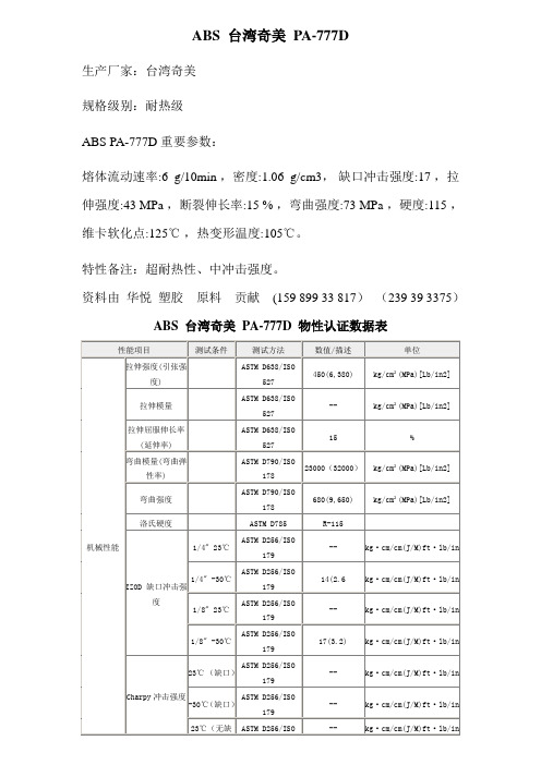
ABS 台湾奇美PA-777D生产厂家:台湾奇美规格级别:耐热级ABS PA-777D重要参数:熔体流动速率:6 g/10min ,密度:1.06 g/cm3,缺口冲击强度:17 ,拉伸强度:43 MPa ,断裂伸长率:15 % ,弯曲强度:73 MPa ,硬度:115 ,维卡软化点:125℃,热变形温度:105℃。
特性备注:超耐热性、中冲击强度。
资料由华悦塑胶原料贡献(159 899 33 817)(239 39 3375)ABS 台湾奇美PA-777D 物性认证数据表性能项目测试条件测试方法数值/描述单位机械性能拉伸强度(引张强度)ASTM D638/ISO527450(6,380) kg/cm²(MPa)[Lb/in2]拉伸模量ASTM D638/ISO527-- kg/cm²(MPa)[Lb/in2]拉伸屈服伸长率(延伸率)ASTM D638/ISO52715 %弯曲模量(弯曲弹性率)ASTM D790/ISO17823000(32000)kg/cm²(MPa)[Lb/in2]弯曲强度ASTM D790/ISO178680(9,650) kg/cm²(MPa)[Lb/in2]洛氏硬度ASTM D785 R-115IZOD 缺口冲击强度1/4" 23℃ASTM D256/ISO179-- kg·cm/cm(J/M)ft·lb/in 1/4" -30℃ASTM D256/ISO17914(2.6 kg·cm/cm(J/M)ft·lb/in 1/8" 23℃ASTM D256/ISO179-- kg·cm/cm(J/M)ft·lb/in 1/8" -30℃ASTM D256/ISO17917(3.2) kg·cm/cm(J/M)ft·lb/in Charpy冲击强度23℃ (缺口)ASTM D256/ISO179-- kg·cm/cm(J/M)ft·lb/in -30℃(缺口)ASTM D256/ISO179-- kg·cm/cm(J/M)ft·lb/in 23℃(无缺ASTM D256/ISO -- kg·cm/cm(J/M)ft·lb/in口)179-30℃(无缺口)ASTM D256/ISO179-- kg·cm/cm(J/M)ft·lb/in物性性能比重(密度)ASTM D792/ISO11831.06成型收缩率ASTM D955 -- %熔融指数(流动系数)200℃/5kgASTM D1238/ISO1133-- g/10min 220℃/10kgASTM D1238/ISO11335.5 g/10min 吸水率23℃/24H ASTM D570/ISO 62 -- %热性能热变形温度退火ASTM D648/ISO 75 115(239) ℃(℉)未退火ASTM D648/ISO 75 105(221) ℃(℉)维卡软化点ASTM D1525/ISOR306125(257) ℃(℉)熔点- -- ℃(℉)燃烧性(率)UL94 1.6mmHB线性膨胀系数ASTM D696/ISO11359-- mm/mm.℃加工条件干燥条件90~105°C下烘料约3小时加工温度射嘴220~250°C℃料筒前段230~250 °C℃料筒中段230~250 ℃℃料筒后段220~240 ℃℃熔体温度-- ℃模具温度30~70°C℃压力注塑压力50~70kg/cm²Mpa保压压力40~60kg/cm²Mpa 背压5~15kg/cm²Mpa 螺杆转速-- rpm其他备注在射出周期中勿将热融胶长期停留在加热管中颜色--特性超耐热性、中冲击强度用途发热家电外壳 / 乾发吹风筒 / 熨斗外壳 / 暖风机 / 汽车零配件如仪表板/ 水箱护罩等。
采用tma4000测定材料熔点和软化点-仪器谱
采用TMA4000测定材料熔点和软化点材料的基本特征之一—无论是塑料、金属或者陶瓷—是它的熔点。
一台DSC 能够确定结晶熔融发生时有吸热现象所对应的温度,或者在玻璃化转变的地方有热容的增加,同样也可以用机械分析仪来确定在何温度下样品由刚性变软或弯曲—即模量显著降低。
动态机械分析DMA 给出了最宽范围内的模量变化定量数据,但是通常采用热机械分析TMA 这种更简便的测试手段,足以对材料加热时变软的变化加以定性或定量分析。
为满足更宽范围内各种样品的测试要求,TMA 采用压缩、柔性变形(弯曲)和拉伸等特定的探头来适应多种几何形状的样品。
当一个样品加热到它的熔点时,它在探头施加的力的作用下变形。
TMA 探测并记录下样品高度随温度变化的变化。
这种方法是某些工业上常用熔点测试的基本方法,为求简单快速,大多采用TMA 进行测试。
应用文献简介Author:Bruce Cassel Kevin Menard PerkinElmer, Inc.Shelton, CTTMA4000分析仪特别适合于进行快速和可靠的熔融测量方法的要求。
图1显示的是这台仪器的断面图。
这里自下而上给出了它所具有的特点:度,并且如果发生大尺寸的变化也可以跟踪。
LVDT 是温度恒定的,这样可以使它的输出不受炉温和实验室温度的影响。
一个阿基米德浮体(完全浸没)支撑了样品探头及中心杆的重量。
这就提供了对环境震动的阻滞和装样品或停电时对自由下落的石英附件的保护。
为什么其他生产厂家不提供这种独特和有用的特性呢?因为他们宁愿给他们的TMA 提供准DMA 的功能。
力传感器同样也是宽范围的线性的,只根据TMA 使用者的选择提供向上或向下的力(因为它不需要支持探头和中心杆的重量)。
压缩下的软化最简单形式的软化点测试方法是把一个样品放进TMA 中,然后施加一个力将平头探杆降到样品上,然后加热。
(图2)有两种不同平头端的探杆可供选择来施加合适大小的应力。
图3显示的是铝饮料罐上的一层涂层材料的软化点的测量曲线。
维卡软化点测定

负荷热变形温度的测定负荷热变形温度是衡量塑料耐热性的主要指标之一。
方法原理把一个具有一定尺寸要求的矩形试样,放在跨度为100mm的支座上,并在两支座的中点处,施加规定的负荷,形成三点式简支梁式静弯曲,负荷力的大小,必须使试样形成1.81N/mm2或0.45N/mm2的表面弯曲应力,把受荷后的试样浸在导热的液体介质中,以120℃/h的升温速度升温,当试样中点的变形量达到与试样高度相对应的规定值时,读取其温度,这就是负荷热变形温度。
方法要点1)仪器加热浴箱中的液体热介质,应选取在试验过程中对试样不造成溶胀、软化、开裂等影响的液体,对于大部分塑料,选用硅油较合适。
2)试样试样为一矩形样条,其长度为120mm,高为9.8~15mm之间,其厚度对于模塑材料为3.0~4.2mm ,对于板材可用板材原始厚度3~13mm 的范围,如板材的厚度大于13mm ,则应在其一面机械加工至符合要求的厚度。
3)测定首先要精确测量试样的尺寸,再根据试样实际的尺寸计算出负荷力的大小,计算公式如下:Lbd F 322σ=式中:F ——负荷力,N ; b ——试样宽度,mm d ——试样高度,mm L ——支座间距离,100mmσ——试样公称表面应力(1.81N/mm 2或0.45N/mm 2)。
根据计算出来的力,调节试样的负荷,试验设备中的负荷杆及变形测量装置的附加力都应计入总负荷之中。
其后按规定进行升温,当试样中点的变形量达到规定值时,读取其温度即为负荷热变形温度。
还需指出,试样高度的变化不但要改变负荷力的大小,而且对试验终了时的中点变形量也要作出相应的改变。
试样高度与标准变形量对应关系见下表表试样高度同标准变形量关系试验方法标准中,规定了可选用两种表面应力,但对于0.45N、mm2的应力,由于试样所受的力较小,而试样尺寸的测量,仪器附加力的计算及传力杆摩擦等因素所产生的误差基本上是一个定数,因此其相对误差较大。
测试结果也表明,采用小负荷时其数据分散性较大,因此一般不采用小负荷。
HDT和维卡软化点
• 维卡软化试验是1894年维卡尔提出,1910最先由德国正式建 立原则措施。
• 我国1970年采用这一试验措施用于测试热塑性塑料旳热性能, 1979年建立国标。
• (一)测试原理
• 伴随温度旳提升,材料抵抗外力旳能力下降,在恒定外力作用 下压针头刺入试样旳深度因之逐渐加深。
• 当要求针入量为一定值(1mm)时,多种热塑性塑料到达该针入 量时旳温度就各自为一定值。
•测试措施: •测试原则:GB/T1633—2023
•维卡软化点试验装置与热变形温度测试旳基本一样。 由支架、保温浴槽、液体传热介质、砝码、测温装置、 变形测量装置和冷却装置等构成。
•压针头平端与负载杆成直角,截面积为1mm2。 •测试图:
• 采用小负荷时,其数据分散性较大,相对误差较大。
• 蠕变较大旳塑料如聚乙烯、尼龙等材料,采用小负荷。
• 4)将试样对称地放在试样支座上,高度为15mm旳一面垂 直放置,插入温度计,温度计水银球在试样两支座旳中点附 近,与试样相距在3mm以内,不要触及试样。
• 把装好试样旳支架小心放入保温浴槽内,试样应位于液面 35mm下列,加上砝码,开动搅拌器,5min后调整变形测 量装置,使之为零。
•测试条件: •等速升温:A:5±0.5℃/6min;B:12±1.0℃/6min。 •砝码大小:9.81N(1000gf);49.05N(5000gf) •试验时旳起始温度可取室温。 •以压针头刺入试样旳量1mm为试验终点。 •试样要求: •试样厚度应在3~6mm范围,宽和长至少为10×10mm,或直径 不小于10mm旳圆片。 •模塑试样厚度应在3~4mm范围。 •板材试样取原厚,超出6mm时,单面加工成3~4mm •不足3mm时,由2~3块迭合成厚度不小于3mm使用。 •试样旳支撑面和受测面应平行,表面平整光滑,无气泡,无锯 切痕迹,凹痕或飞边等缺陷, •按产品原则要求进行预处理。 •每组试样为2个。
亚克力 维卡软化温度
亚克力维卡软化温度
亚克力,也称为聚甲基丙烯酸甲酯(PMMA),是一种常见的透
明塑料材料,具有良好的透明度、耐候性和耐化学性。
维卡软化温
度是指亚克力材料在加热过程中开始软化的温度。
一般来说,维卡
软化温度是亚克力材料的重要物理特性之一,可以影响其在不同环
境条件下的应用。
亚克力的维卡软化温度通常在70°C至115°C之间,具体数值
取决于制造商和材料的配方。
在达到软化温度后,亚克力材料会开
始变软并失去其原有的强度和硬度,因此在设计和应用中需要考虑
到这一特性。
维卡软化温度对于亚克力材料的加工和使用具有重要意义。
在
加工过程中,了解材料的软化温度可以帮助确定加工参数,避免过
热导致材料变形或损坏。
在实际使用中,了解软化温度可以帮助选
择合适的材料,以确保其在预期温度范围内保持结构稳定性。
除了维卡软化温度,亚克力材料的热变形温度也是需要考虑的
参数。
热变形温度是指材料在加热过程中开始发生可见变形的温度,通常高于软化温度。
这两个温度参数可以帮助工程师和设计师更好
地理解和应用亚克力材料。
总的来说,亚克力的维卡软化温度是一个重要的物理特性,对于材料的加工和应用具有重要意义。
通过了解和掌握这一参数,可以更好地选择和应用亚克力材料,确保其在特定温度条件下表现稳定和可靠。
维卡软化点温度测定仪采购要求11采购一台维卡软化点温度测定

维卡软化点温度测定仪一、采购要求1.1采购一台维卡软化点温度测定仪用于电线电缆绝缘料材料性能检测,投标设备须满足以下标准对试验设备的要求:GB/T 15065-2009 电线电缆用黑色聚乙烯塑料GB/T 1633-2000 热塑性塑料维卡软化温度(VST)的测定YD∕T 1020.1-2004 电缆光缆用防蚁护套材料特性第一部分聚酰胺YD∕T 1020.2-2004 电缆光缆用防蚁护套材料特性第二部分聚烯烃共聚物ISO 306-2013 塑料--热塑性材料--维卡软化温度(VST)的测定ASTM D1525-2007 塑料维卡(Vicat)软化温度的测试方法1.2技术要求1.2.1仪器可同时对6只样品测试,并独立记录和显示试验结果;1.2.2仪器控制单元在达到样品上产生规定压痕时,切断加热器电源并发出声光报警;1.2.3仪器应具有清晰如功能标识、砝码标识、安全标识、电气线路标识等;1.2.4投标文件须说明仪器主要功能、特点、精度、主要部件材质/品牌/型号等;1.2.5投标文件须说明负载杆、金属架、试样架、压针制造材质、其材质的标准热膨胀系数、部件表面光洁度;1.2.6投标文件须说明负载杆与刚性金属架设计原理和摩擦副种类;1.2.7投标文件须说明测量压针移动距离测量器具(千分表或其他)品牌、型号、精度,(采用机械式千分表(带有指针弹簧)时,千分表弹簧所施加的向上力如何在载荷中减去);1.2.8投标文件须说明加热设备温控范围、功率、功能、安全保护、温控精度、温场偏差、操作方式等;1.2.9投标文件须说明加热浴/烘箱应使用防腐、耐热材料制造,须说明制造材料和壁厚;1.2.10投标文件须说明传感器种类、精度、固定方式、是否可向样品方向调节间距;1.2.11投标方有义务提供关于仪器的其他信息,便于招标方了解投标仪器;1.2.12投标文件应有技术偏离表,对以上各条款逐一响应,并明确正偏离或负偏离;1.2.13投标文件须提供试验系统的多角度图片(最好是实物图片);1.2.14投标文件须提供近2年来同类设备销售记录证明文件如合同(可隐藏敏感信息);1.2.15供货仪器提供使用说明书、质量保证书、出厂合格证、校准证书、电气原理图、机械原理图等文件;1.2.16供货仪器提供仪器配装的电气元件随机文件,便于设备维护;1.2.17供货仪器提供压针一套(6支)、备用压针一套(6支);1.2.18投标仪器应随机提供空白试验试样3只以上:GB/T 1633-2000“用低膨胀系数的刚性材料(如瓦镍铁合金或硅硼玻璃)制备的试样,对仪器温度范围做空白试验进行校正,并对温度确定一个校正项。
HDPE物性数据表

①原料描述部分规格级别:电缆绝缘料外观颜色:本色用途概述:用于低、中、高速绝缘生产线备注说明:性能:由乙烯、丁烯集合而成的双峰高密度聚乙烯,并含有适量助剂的本色粒料。
因为其分子量呈双峰分布,所以它具有优异的加工性能、很好的力学性能及良好的电性能。
②原料技术数据性能项目试验条件[状态]测试方法测试数据数据单位基本性能密度//0.941-0.959g/cm3熔体流动速率//≤1.0g/10min机械性能拉伸强度//≥19.0MPa 断裂伸长率//≥400%耐环境应力开裂性48h/≤2/10/电气性能介电常数1MHz/≤2.40/体积电阻率//≥1×1013Ω?m①原料描述部分规格级别:挤出级外观颜色:---用途概述:用途:供水管,工业用管子。
备注说明:特性:电子光谱法,高冲击和高强度。
②原料技术数据性能项目试验条件[状态]测试方法测试数据数据单位基本性能熔体流动速率/ASTM D-12380.12g/10min 密度/ASTM D-15050.950g/cm3机械性能屈服拉伸强度/ASTM D-638220Kg/cm2断裂拉伸强度/ASTM D-638390Kg/cm2最终拉伸率/ASTM D-638>500%挠曲强度/ASTM D-7478,500Kg/cm2洛氏硬度/ASTM D-78550R冲击强度/ASTM D-25630kg?cm/cm 耐环境应力破裂/ASTM D-1693>1,000F50hr热性能脆化温度/ASTM D-746<-80℃熔点/ASTM D-2117131℃维卡软化点/ASTM D-1525122℃①原料描述部分规格级别:管材级外观颜色:---用途概述:农业排灌管、热水管、支架备注说明:类型:挤塑②原料技术数据性能项目试验条件[状态]测试方法测试数据数据单位基本性能熔体流动速率//0.15g/10min 密度//0.954g/cm3机械性能拉伸强度//18.0MPa其它性能粉末灰分//0.03%①原料描述部分规格级别:挤出级外观颜色:本色、圆柱状或扁圆状颗粒用途概述:用于制造日用品和各类工、农业用品,如薄膜、中空容器、管道、单丝、延伸带、电绝缘制品等。
最新Lexan945U

材质说明:的Lexan * 945U聚碳酸酯(PC)树脂是一种非填充的,可注射成型级。
这种非氯化,非溴化阻燃PC有UL-94 V0阻燃等级和紫外线稳定,可提供额外的耐候能力。
Lexan树脂945U可在各种不透明的颜色选项是一个一般用途的树脂,为各种各样的应用的理想选择。
这些数据提供SABIC。
卖方:注意:此处包含的信息是典型值,供参考和比较之用。
他们不应该被用作设计规格或质量控制的基础。
联系我们索取完整的材料性能数据表。
详细资料请咨询186-****2303何先生本公司--供--应--各--种--工--程--塑--料物理性质公英语评论比重 1.19克/立方厘米1.19克/立方厘米ASTM D 792线性模具收缩,流动0.0060 -0.0080厘米/厘米,厚3.20毫米@厚度在0.1260.0060 -0.0080 /沙伯基础方法熔体流动10 g/10分钟@负荷1.20公斤,温度300℃10 g/10分钟负载时的2.65磅,温度572°FASTM D 1238力学性能公英语评论拉伸断裂强度65.0兆帕9430 PSI 键入我,50毫米/分钟; ASTM D 638 抗拉强度,屈服62.0兆帕8990磅键入我,50毫米/分钟; ASTM D 638 断裂伸长率125%125%键入我,50毫米/分钟; ASTM D 638 伸长率 6.0% 6.0%键入我,50毫米/分钟; ASTM D 638 拉伸模量 2.27 GPA 329 KSI 50毫米/分钟,ASTM D 638 弯曲屈服强度101兆帕14600磅 1.3毫米/分钟,50毫米跨度ASTM D 790 弯曲模量 2.34 GPA 339 KSI 1.3毫米/分钟,50毫米跨度ASTM D 790悬臂梁缺口冲击强度8.01焦耳/平方厘米温度23.0°C15.0 ft-lb/in温度73.4°FASTM D 256冲击试验73.0Ĵ@温度23.0°C 53.8磅-英尺@温度73.4°F仪器化冲击总能量; ASTM D 3763电气特性公英语评论耐电弧性0.00 - 60秒0.00 - 60秒钨,PLC码7,ASTM D 495 对比跟踪指数175 - 250 V 175 - 250 V PLC代码3,UL 746A 热丝引燃,HW I 30 - 60秒30 - 60秒PLC代码2,UL 746A 高安培电弧点火,海30 - 60弧30 - 60弧表面上看,PLC代码2,UL 746A 高压电弧跟踪速率,毫米分代码,HVTR /分钟钟热性能公英语评论膨胀系数,线性,平行流66.6μm/m-°C温度-40.0 - 40.0℃37.0μin/in-°F温度-40.0 - 104°FASTM E 831膨胀系数,线性,横向流动66.6μm/m-°C温度-40.0 - 40.0℃37.0μin/in-°F温度-40.0 - 104°FASTM E 831在0.46兆帕的热变形温度(66磅)137°C@厚3.20毫米279°F@厚度在0.126未退火ASTM D 648热变形温度在1.8兆帕(264磅)126°C@厚3.20毫米259°F@厚度在0.126未退火ASTM D 648维卡软化点143°C 289°F 汇率B/50; ASTM D 1525 UL RTI,电气130°C 266°F UL 746B UL RTI,机械冲击120°C 248°F UL 746B UL RTI,不影响机械130°C 266°F UL 746B易燃,UL94 V-2厚度0.800毫米V-2@厚度0.0315UL 94V-0 @厚度1.52毫米V-0@厚度0.0598UL 94灼热丝试验850°C@厚1.00毫米1560°F@厚度0.0394灼热丝可燃性温度IEC 60695-2-13960°C @厚1.00毫米1760°F@厚度0.0394灼热丝燃烧指数; IEC 60695-2-12描述性属性紫外线光,水曝光/浸泡F1 UL 746C财务处长工作总结[财务处长工作总结]财务处长工作总结尊敬的各位领导、同志们:光阴似箭、岁月如梭,转眼之间一年过去了,新的一年已经开始,财务处长工作总结。
- 1、下载文档前请自行甄别文档内容的完整性,平台不提供额外的编辑、内容补充、找答案等附加服务。
- 2、"仅部分预览"的文档,不可在线预览部分如存在完整性等问题,可反馈申请退款(可完整预览的文档不适用该条件!)。
- 3、如文档侵犯您的权益,请联系客服反馈,我们会尽快为您处理(人工客服工作时间:9:00-18:30)。
Designation:D1525–06Standard Test Method forVicat Softening Temperature of Plastics1This standard is issued under thefixed designation D1525;the number immediately following the designation indicates the year of original adoption or,in the case of revision,the year of last revision.A number in parentheses indicates the year of last reapproval.A superscript epsilon(e)indicates an editorial change since the last revision or reapproval.This standard has been approved for use by agencies of the Department of Defense.1.Scope*1.1This test method covers determination of the tempera-ture at which a specified needle penetration occurs when specimens are subjected to specified controlled test conditions.1.2This test method is not recommended for ethyl cellu-lose,nonrigid poly(vinyl chloride),poly(vinylidene chloride), or other materials having a wide Vicat softening range.1.3The values stated in SI units are to be regarded as standard.1.4This standard does not purport to address all of the safety concerns,if any,associated with its use.It is the responsibility of the user of this standard to establish appro-priate safety and health practices and determine the applica-bility of regulatory limitations prior to use.N OTE1—This test method and ISO306:1987(E)are technically equiva-lent,with the exception of the allowance for creep,prior to beginning the test,in this test method.2.Referenced Documents2.1ASTM Standards:2D618Practice for Conditioning Plastics for TestingD883Terminology Relating to PlasticsD1898Practice for Sampling of Plastics3E1Specification for ASTM Liquid-in-Glass Thermometers E77Test Method for Inspection and Verification of Ther-mometersE220Test Method for Calibration of Thermocouples By Comparison TechniquesE644Test Methods for Testing Industrial Resistance Ther-mometersE691Practice for Conducting an Interlaboratory Study to Determine the Precision of a Test MethodE1137/E1137M Specification for Industrial Platinum Re-sistance Thermometers2.2ISO Standards:4ISO306Plastics—Thermoplastic Material—Determination of Vicat Softening Temperature3.Terminology3.1Definitions—Definitions of plastics used in this test method are in accordance with those defined in Terminology D883,unless otherwise specified.3.1.1Vicat softening temperature—the temperature at which aflat-ended needle of1-mm2circular cross section will penetrate a thermoplastic specimen to a depth of1mm under a specified load using a selected uniform rate of temperature rise.4.Summary of Test Method4.1Aflat-ended needle loaded with a specified mass is placed in direct contact with a test specimen.The mass applied can be one of two accepted loads,as follows:Loading1—1060.2NLoading2—5061.0NThe specimen and needle are heated at either of two permis-sible rates,as follows:Rate A—5065°C/hRate B—120610°C/hThe temperature at which the needle has penetrated to a depth of160.01mm is recorded as the Vicat softening temperature.5.Significance and Use5.1Data obtained by this test method may be used to compare the heat-softening qualities of thermoplastic materi-als.5.2This test method is useful in the areas of quality control, development,and characterization of plastic materials.6.Apparatus6.1The equipment shall be constructed essentially as shown in Fig.1and shall consist of the following:1This test method is under the jurisdiction of ASTM Committee D20on Plastics and is the direct responsibility of Subcommittee D20.30on Thermal Properties (Section D20.30.07).Current edition approved March15,2006.Published April2006.Originally approved st previous edition approved in2000as D1525-00.2For referenced ASTM standards,visit the ASTM website,,or contact ASTM Customer Service at service@.For Annual Book of ASTM Standards volume information,refer to the standard’s Document Summary page onthe ASTM website.3Withdrawn.4Available from American National Standards Institute(ANSI),25W.43rd St.,4th Floor,New York,NY10036.*A Summary of Changes section appears at the end of this standard.Copyright©ASTM International,100Barr Harbor Drive,PO Box C700,West Conshohocken,PA19428-2959,United States.6.1.1Immersion Bath —The bath containing the heat-transfer medium shall be equipped with a stirrer,temperature-measuring device,and heater.The heater shall have automatic control of the selected bath temperature-rise rate (see 4.1).The bath should be constructed to allow the specimens to be submerged at least 35mm below the surface of the heat-transfer medium.6.1.2Heat-Transfer Medium —Several liquids,such as sili-cone oils,glycerine,ethylene glycol,and mineral oil have been used successfully for various plastics.5The medium used shall be free from contaminants and shall have no short-time effect at elevated temperatures on the material being tested,and shall be of low viscosity at room temperature.The results of the test may depend on the thermal diffusivity of the heat-transfer medium.N OTE 2—It is desirable to have a method of cooling the bath in order to reduce the time required to lower the temperature of the bath between tests.This may be accomplished by using a cooling coil installed in the bath or an external heat-transfer system.If the temperature rise rate is adversely affected by the presence of residual coolant in the cooling coils,the coolant should be purged prior to beginning the test.6.1.3Specimen Support —A suitable stand or support for the specimen to be placed in the bath.The vertical members that attach the specimen support to the upper plate shall be made of a material having the same coefficient of expansion as that used for the rod through which the load is applied in order that the penetration-measuring device reading caused by differential expansion over the intended temperature range does not exceed 0.02mm when the specimen is replaced by a piece of heat-resistant material.66.1.4Penetration-Measuring Device —The device used for measuring the penetration of the specimen shall be capable ofmeasuring a penetration depth of at least 160.01mm.The measuring device may be an analog or digital dial gauge or similar device,including an electronic-displacement sensing apparatus.6.1.5Masses —A set of masses of suitable sizes shall be supplied so that the net force on the needle point shall be equal to 1060.2N (Loading 1)or 5061.0N (Loading 2)when the apparatus is assembled.The net force shall consist of the weight of the needle rod assembly,the force attributed to action of the penetration-measuring device,and the extra weight that is required to balance the system.The required mass is calculated as follows:Required mass,m w 5~F 2F s !/9.806652m rF =total force to be applied to the specimen,N,F s=force exerted by any penetration-measuring device,N (this is a positive value if the thrust of the spring is towards the specimen (downward),a negative value if the thrust of the spring is opposing the descent of the rod,or zero if no such device is involved),m r =mass of the needle rod assembly,kg,andm w =extra mass applied to attain the desired force,kg.Verification of the load should be made on new equipment and after replacing penetration-measuring devices,or at any time to ensure that the equipment is in calibration.The calibration procedure for dial-gauge-type penetration-measuring devices is described in Appendix X1and Appendix X2.The methods for determination of the thrust contributed by dial-gauge-type penetration-measuring devices are also given in Appendix X1and Appendix X2.6.1.6Temperature-Measuring Device —A thermocouple,re-sistance thermometer (RTD),or thermometer adequate to cover the range being tested.The thermometer shall be one of the following,or its equivalent,in accordance with Specification E 1:Thermometer 1C or 2C,having ranges from −20to 150°C5Silicone oils having a room temperature viscosity of 100cP have been found satisfactory and safe for short-term heat cycles up to 260°C.6Borosilicate glass has been found satisfactory for thispurpose.FIG.1Apparatus for Softening TemperatureDeterminationor−5to300°C,respectively,depending on the test range.The thermocouple or resistance thermometer and related electronics shall be accurate to at least60.5°C.Mercury-in-glass ther-mometers shall be calibrated for the depth of immersion in accordance with Test Method E77.Thermocouples shall be calibrated in accordance with Test Method E220.Resistance thermometers shall comply with the requirements of Test Methods E644and Specification E1137/E1137M.6.1.7Needle—Aflat-tipped,hardened steel needle with a cross-sectional area of1.00060.015mm2(diameter of1.120 to1.137mm)shall be used.The tip shall be free of burrs and be perpendicular to the axis of the rod.The needle shall protrude at least2mm from the end of the rod.7.Sampling7.1Unless otherwise agreed upon between the seller and the purchaser,sample in accordance with the sections on General Sampling Procedures and Specific Sampling Procedures of Practice D1898.Sampling based on engineering principles, prior to packaging,shall be considered an acceptable alterna-tive.8.Test Specimen8.1Use at least two specimens to test each sample.The specimen shall beflat,between3and6.5mm thick,and at least 10by10mm in area or10mm in diameter.When necessary to use multiple layers,no more than three layers of material may be stacked in order to achieve the minimum thickness.The specimens may be cut from sheet or molded material.The type of mold and the molding process used to produce test speci-mens will affect the results obtained in the test.Molding conditions shall be in accordance with the standard for the material being tested or should be agreed upon between the cooperating laboratories.N OTE3—Discrepancies in test results due to variations in molding conditions may be minimized by annealing the test specimens before the test.Since different materials require different annealing conditions, annealing procedures shall be employed only if required by the material standard or if agreed upon between the cooperating laboratories.9.Conditioning9.1If conditioning of the specimens is required,the test specimens shall be conditioned at2362°C and at5065% relative humidity for not less than40h in accordance with Practice D618.N OTE4—Conditioning periods less than the40h,as specified by Practice D618,may be used when it is shown that the Vicat softening temperature is not affected by the shorter conditioning time.Longer conditioning times may be required for some materials that take longer to reach temperature and humidity equilibrium.Refer to the applicable ASTM standards for those materials.10.Procedure10.1Prepare the immersion bath so that the temperature of the heat-transfer medium is between20and23°C at the start of the test unless previous tests have shown that for a particular material under test no error is introduced by starting at a higher temperature.The bath should be well stirred.N OTE5—Under certain conditions,it may be difficult to bring the temperature of the heat-transfer medium down to20to23°C.In these cases,the test may be started with the bath temperature at30°C.The selection of the starting temperature shall be agreed upon between the cooperating laboratories.10.2Place the specimen,which is at room temperature,on the specimen support so that it is approximately centered under the needle.The needle should not be nearer than3mm to the edge of the specimen.Gently lower the needle rod,without the extra mass,so that the needle rests on the surface of the specimen and holds it in position.10.3Position the temperature measuring device so that the sensing end is located within10mm from where the load is applied to the surface of the specimen.The sensing end should not touch the specimen.10.4Lower the assembly into the bath,taking care not to jar it in any way that would damage or dislodge the specimen.10.5Apply the extra mass required to increase the load on the specimen to1060.2N(Loading1)or5061.0N (Loading2).After a5-min waiting period,set the penetration indicator to zero.10.6Start the temperature rise.The rate of temperature increase shall be either5065°C/h(Rate A)or120610°C/h (Rate B)and shall be uniform throughout the test.The Rate A heating requirement shall be considered to be met if over every 12-min interval during the test,the temperature of the bath rises1061°C at each specimen location.The Rate B heating requirement shall be considered to be met if over every6-min interval during the test,the temperature of the bath rises 1261°C at each specimen location.The selection of the rate of rise shall be agreed upon between cooperating laboratories. See Annex A1for calibration of single temperature probe units.10.7Record the temperature of the bath when the needle has penetrated160.01mm into the test specimen.Take care to ensure that an accurate reading of the temperature is made since the rate of penetration of the specimen will be increasing rapidly at this point.10.8Express the Vicat softening temperature as the arith-metic mean of the temperature of penetration of all specimens tested.If the range of penetration temperatures for the indi-vidual test specimens exceeds2°C,record the individual results and repeat the test,using at least two new specimens. N OTE6—If a permanent record is desired,either read and record the penetration for each5°C rise in temperature until the penetration reaches 0.4mm,and at2°C intervals thereafter,or attach a displacement transducer,having the same resolution as the gauge,to each rod and continuously record the rate of penetration by means of a multichannel recorder or similar data-acquisition device.N OTE7—Some commercially available instruments record the time at which the penetration reaches a set depth.If this type of instrument is used,make a time-temperature calibration before the specimens are tested. This calibration compensates for slight variations in the heating rate. (Warning—Even though the variations may be within the specifications set forth in10.6,the compounded error over the range of the test can produce a substantial error in the Vicat softening temperature.)11.Report11.1Report the following information:11.1.1Reference to this test method,11.1.2Complete identification of the materialtested,11.1.3Method of preparing test specimens,including con-ditioning and annealing methods used,11.1.4Initial starting temperature,11.1.5Rate of temperature rise,Rate A (50°C/h)or Rate B (120°C/h),11.1.6Total load applied to the specimen,Loading 1(1060.2N)or Loading 2(5061.0N),11.1.7Thickness of the specimen and the number of layers of the material that were used,11.1.8Heat-transfer medium,11.1.9Vicat softening temperature,expressed as the arith-metic mean of the Vicat softening temperatures of the indi-vidual specimens,and11.1.10Any observations relating to the test.12.Precision and Bias 712.1Precision —Tables 1and 2have been developed in accordance with Practice E 691.Table 1,for the case using Loading 1(1060.2N)and Heating Rate B (120610°C/h)is based on round-robin tests conducted in 1982involving five materials and differing numbers of laboratories as noted in the table.Each laboratory obtained three test results for each material.Table 2,for the case using Loading 2(50.061.0N )and Heating Rate A (5065°C/h)is based on round-robin tests conducted in 1994involving 8materials and six laboratories.Each laboratory obtained two test results for each material.In both cases,for each material,all of the individual specimensfrom all material samples were prepared by one source.Each test result was the average of two individual determinations.(Warning—The following explanations of r and R (see 12.1.1-12.1.1.3)are intended only to present a meaningful way of considering the approximate precision of this test method.The data given in Tables 1and 2should not be applied rigorously to the acceptance or rejection of material,as those data are specific to the round-robin test and may not be representative of other lots,conditions,materials,or ers of this test method should apply the principles outlined in Practice E 691to generate data specific to their laboratory and materi-als,or between specific laboratories.The principles of 12.1.1-12.1.1.3would then be valid for such data.)12.1.1Concept of r and R —If S r and S R have been calcu-lated from a large enough body of data,and for test results that were averages from testing two specimens,the following applies:12.1.1.1Repeatability,r —In comparing two test results for the same material obtained by the same operator using the same equipment on the same day,the two test results obtained within one laboratory shall be judged as not equivalent if they differ by more than the “r ”value for that material.“r ”is the interval representing the critical difference between two test results for the same material,obtained by the same operator using the same equipment on the same day in the same laboratory.12.1.1.2Reproducibility,R —In comparing two test results for the same material obtained by different operators using different equipment in different laboratories on different days,the two test results obtained by different laboratories shall be7Supporting data are available from ASTM Headquarters.Request RR:D20:1194.TABLE 1Vicat Softening Temperature Using Loading 1and Rate B,Values Expressed in Units of °CMaterialAverage S r A S R B r C R DNumber of ParticipatingLaboratoriesEthylene vinyl acetate 72.4 1.44 2.29 4.03 6.4010Polystyrene 97.30.68 2.36 1.91 6.6210High-density polyethylene 127.9 1.04 2.73 2.907.6310Polypropylene 152.5 1.13 2.83 3.167.9110Nylon 66251.20.705.061.9614.167A S r =within-laboratory standard deviation of the average.BS R =between-laboratories standard deviation of the average.Cr =within-laboratory repeatability limit =2.8S r .DR =between-laboratories reproducibility limit +2.8S R .TABLE 2Vicat Softening Temperature Using Loading 2and Rate A,Values Expressed in Units of °CMaterialAverage S r A S R B r C R D Polypropylene (PP0343)56.2 1.07 1.86 2.99 5.22Polypropylene (PP0114)92.5 1.47 4.08 4.1211.44Impact Modified Acrylic (PMMA0230V1)94.10.32 1.960.91 5.48ABS94.40.62 1.61 1.74 4.52High Heat ABS (ABS0135)100.80.34 1.530.95 4.29Unmodified Acrylic (PMMA0141V3)105.10.44 1.48 1.23 4.15Polycarbonate (PC0136)143.60.19 1.240.53 3.48Polycarbonate (PC0123)143.80.381.031.052.89AS r =within-laboratory standard deviation for the indicated material.It is obtained by pooling the within-laboratory standard deviations of the test results from all of the participating laboratories:S r =[[(S 1)2...+(S n )2]/n]1/2BS R =between-laboratories reproducibility,expressed as standard deviation:S R =[S r 2+S L 2[1/2where S L =standard deviation of laboratory means.Cr =within-laboratory critical interval between two test results =2.83S r .DR =between-laboratories critical interval between two test results =2.83S R.judged not equivalent if they differ by more than the“R”value for that material.“R”is the interval representing the critical difference between two test results for the same material, obtained by different operators using different equipment in different laboratories.12.1.1.3Any judgment in accordance with12.1.1or 12.1.1.1would have an approximate95%(0.95)probability of being correct.12.2Bias—There are no recognized standards by which to estimate the bias of this test method.13.Keywords13.1plastics;thermoplastics;Vicat softening temperatureANNEXES(Mandatory Information)A1.CALIBRATION OF SINGLE-(CENTRALIZED)TEMPERATURE PROBE UNITSA1.1If the unit in operation is of the type that has only one temperature probe in the bath,and this probe is monitored to record the softening temperature of the specimen at all the stations in the unit,then the following calibration and checks must be undertaken to ensure comparable results with units that have a temperature probe at each station.A1.2This procedure must be performed annually as a minimum to ensure proper temperature distribution and accu-racy of probe and display.A1.3Calibration will require the use of temperature meter and probe traceable to NIST,with accuracy and display resolution of0.1°C or better,a stopwatch,and any tools needed to open and adjust the unit.A1.3.1Low-temperature calibration of the unit is accom-plished by placing the NIST-traceable probe within10mm of specimen height,in the bath at three different points in the bath. The three points will be at the center and left and right ends of the bath.Start with the station closest to the centralized probe, while the unit is programmed to maintain a constant tempera-ture between20and50°C,with all stirrers operating.Allow the bath to stabilize for a minimum of5min.Read and record the readout of the calibrated probe and the units internal tempera-ture display to the nearest0.1°C.Make any necessary adjust-ments to the unit’s temperature controller to bring the bath to 60.1°C of the bath set point,allowing a stabilization time of a minimum of5min between adjustment(s)and readings.Once the calibrated probe indicates the bath is at the set point,make adjustments to the centralized probe’s display as necessary. A1.3.1.1Move the NIST-traceable probe to the other two points maintaining the probe within10mm of specimen height. Read and record the temperatures at these points,after allow-ing the probe to stabilize a minimum of5min.A1.3.2High-temperature calibration will be accomplished by programming the unit to maintain an elevated temperature near,but not exceeding,the highest temperature allowed by the heat transfer media.All covers and stations must be in place and stirrer motors operating.Place the NIST probe within10 mm of specimen height at the station closest to the centralized probe,and allow the bath to stabilize for a minimum of5min. Read and record the readout of the calibrated probe and the unit internal temperature display to the nearest0.1°C.Make any necessary adjustments to the unit’s temperature controller to bring the bath to60.1°C of the bath set point,allowing a stabilization time of a minimum of5min between adjust-ment(s)and readings.Once the calibrated probe indicates the bath is at the set point make adjustments to the centralized probe’s display as necessary.A1.3.2.1Move the NIST-traceable probe to the other two points maintaining the probe within10mm of specimen height. Read and record the temperatures at these points,after allow-ing the probe to stabilize for a minimum of5min.A1.3.3Evaluate the data from each of the three points in the bath at both low and high temperature.If any point is greater than60.5°C from the set point,have the unit serviced or repaired to correct this error.If it is not possible to correct the bath uniformity to less than0.5°C,then a thermal sensing device must be placed at each station and used to record the temperature of the bath at the time of deflection while running tests.The unit may be electronically modified or the use of glass thermometers(as outlined in6.1.6)may be placed at each station and manually read and recorded at the moment of specimen deflection.A1.3.4If the steps given in A1.3.1-A1.3.2.1have been taken and successfully completed,cool the bath down to a normal start temperature and allow the bath to stabilize.Place the NIST probe at the point in the bath that the preceding gathered data shows the greatest error.Start a test at120°C/h or 50°C/h.Read and record the temperature of both the unit’s display and the readout of the NIST probe.An offset of10to 15s between the two readings is acceptable as long as this interval is maintained throughout this test.Start the stopwatch when thefirst temperature is recorded.Read and record the temperature of the unit’s display and the NIST probe,main-taining any delay interval,if used,every5min for1h.A1.3.5Evaluate the data acquired during the test given in A1.3.4.Ensure that the temperature of the bath is rising at the correct rate as outlined in10.6,at both the centralized probe and the other selected test point.If either is outside the limits for the rate of rise,the unit must be serviced and rechecked before further use.If a unit fails to pass this calibration test the unit must be serviced or replaced.Placing a temperature sensing device at each station will not correct theproblemobserved in A1.3.4,as the unit’s rate of rise is outside the tolerances of this test method.A2.CALIBRATION OF MULTI TEMPERATURE SENSOR INSTRUMENTSA2.1This procedure is to be used in addition to manufac-turer’s requirements and procedures to calibrate a VICAT instrument that has multiple temperature sensors in the bath to control the temperature of the bath,or record the deflection temperature,or both.If the unit under test has only a single temperature sensor please refer to Annex A1.A2.2This procedure shall be performed at a frequency that conforms to the end user’s quality system requirements.A2.3All test equipment,that is,temperature meters,temperature sensors,gauge blocks,stopwatches,etc.,used to perform this procedure must be calibrated and traceable to NIST or other recognized national standards.Temperature measuring equipment must have a resolution of 0.1°C or better,gauge blocks used to calibrate the deflection must be accurate to 0.001mm or better,stopwatches must be accurate to 0.1s or better.A2.4Temperature calibration shall be done in accordance with the manufacturer’s procedures and the following guide-lines:A2.4.1The temperature shall be calibrated at a minimum of two points.One being at or near 8the start temperature of the test and the other at or above the maximum temperature used by the end user.Care must be taken not to exceed the maximum safe temperature of the heat transfer media.A2.4.2If moving the reference temperature sensor(s)from location to location in the bath,a minimum of 5min must be allowed between moving the temperature sensor and reading the temperature values.A2.4.3Test stations and covers shall be in their normal test position when possible and all agitators operating during the calibration.A2.4.4Reference temperature sensor(s)sensitive part shall be placed as close as possible to the Unit Under Test (UUT)sensor(s),and #10mm from the specimens.A2.4.5Adjustment of the UUT shall be made so the display(s)of the UUT is 60.1°C of the values indicated by the reference temperature sensor(s).A2.5Once the static temperature calibration has been completed,cool the instrument down to a normal start tem-perature and allow the bath temperature to stabilize.Program the UUT to ramp up the bath temperature at a rate of 120°C/h or 50°C/h as dictated by the use of the UUT.If the UUT is used at both ramp rates separate tests must be conducted at each ramp rate.Read and record the temperature at each station at intervals not to exceed those stated in section 10.6of this test method,until the UUT reaches the high temperature calibrationpoint.These temperatures shall be read and recorded by software control or data acquisition from the UUT using the internal temperature sensors after they have been calibrated by the above steps or by the use of external traceable temperature measurement equipment.Perform multiple ramps if necessary to verify each station.A2.5.1Evaluate the data acquired during the proceeding test(s)to ensure that the temperature rate of rise at each station is within the tolerances outlined in Section 4of this test method.It is allowable for the first 10min of the ramp to be outside of the prescribed tolerances as many instruments use a PID control for the heating,and it is normal for the controller to tune itself to the correct power and interval requirements to perform the required ramp rate.If any station is found to be outside the prescribed tolerances beyond the first 10min,that station shall not be used for testing until repairs or adjustments are made to bring the station back into tolerance.A2.6A test must be made on each station using a test specimen made of a material having a low coefficient of expansion 9to determine the thermal expansion of the station,load rod and associated parts.The calibrated temperature range of the UUT shall be covered and a compensation value determined at a minimum of each 20°C rate of rise.If the UUT is used at both ramp rates of 120°C/h and 50°C/h then a compensation value must be determined independently for each ramp rate.If this compensation value is greater than 0.02mm [0.0008in.]its algebraic sign shall be noted and the compensation value shall be applied to each test by adding it algebraically to the reading of apparent deflection of the test specimen.It is permissible to perform this test in conjunction with the rate of rise test as outlined in A2.5.A2.7The deflection indicators and critical mechanical dimensions,that is,needle point(s),must also be calibrated/verified using traceable calibration tools.The manufacturer’s requirement and procedures will provide details on how to perform the actual tasks;the following are intended to provide the user with tolerances and other necessary guidelines.A2.7.1The deflection indicators must be calibrated to a tolerance of 60.01mm of the reference.A2.7.2The critical mechanical dimensions must meet the requirements outlined in 6.1.4and 6.1.7of this test method.A2.7.3The weights must be verified and conform to the specification outlined in 6.1.5of this test method.A2.7.4When determining the weight of the load rod(s)and deflection indicator any spring force acting on the specimen must be accounted for.If the design of the apparatus uses a spring force that acts downward (as part of the load)or8Near is defined in this Annex as 65°C.9Borosilicate (quartz)has been found suitable for thispurpose.。
