机械毕业设计英文外文翻译199混凝土泵车液压系统的认识
液压动力系统中英文对照外文翻译文献

中英文对照外文翻译文献(文档含英文原文和中文翻译)原文:FEATURE-BASED COMPONENT MODELS FOR VIRTUALPROTOTYPING OF HYDRAULIC SYSTERMAbstract:This paper proposes a feature-based approach for the virtual prototyping of hydraulic systems. It presents a framework which allows the designer to develop a virtual hydraulic system prototype in a more intuitive manner, i.e. through assembly of virtual components with engineering data. The approach is based on identifying the data required for the development of the virtual prototypes, and separating the information into behaviour, structural, and product attributes. Suitable representations of these attributes are presented, and the framework for the feature-based virtual prototyping approach is established,based on the hierarchical structure of components in a hydraulic system. The proposed framework not only provides a precise model of the hydraulic prototype but also offers the possibility of designing variation classes of prototypes whose members are derived by changing certain virtual components with different features.Key words: Computer-aided engineering; Fluid power systems;Virtualprototyping1.IntroductionHydraulic system design can be viewed as a function-to-form transformation process that maps an explicit set of requirements into a physical realisable fluid power system. The process involves three main stages: the functional specification stage,the configuration design stage, and the prototyping stage.The format for the description of the design in each stage is different.The functional specification stage constitutes the initial design work. The objective is to map the design requirements. To achieve this, the design problems are specified Correspondence and offprint requests to: Dr S. C. Fok, Schoool of Mechanical and Production Engineering, Nanyang Technological University, Nanyang Avenue, Singapore 639798. The designer must identify the performance attributes, which can include pressure, force, speed, and flowrate, with the required properties such as size, cost, safety and operating sequence. performance requirements for each attribute. In this stage, the design is abstracted in terms of the performance attributes with associated values.The objective of the configuration design stage is to synthesise a hydraulic circuit that performs the required functions conforming to the performance standards within defined constraints. A typical hydraulic system is made up of many subsystems. The smallest building block in a subsystem is the standard hydraulic component (such as valves, cylinders,pumps, etc.). Each type of standard component serves a specific elemental function. The design effort in the configuration design stage is fundamentally a search for a set of optimal arrangements of standard components (i.e. hydraulic circuit) to fulfil the functional requirements of the system. Based on this framework, the designers would normally decompose the overall system functions in terms of subfunctions. This will partition the search space and confine the search for smaller hydraulic subcircuits to perform the subfunctions.Computers are often used to support the configuration design process. For example, Kota and Lee devised a graph-based strategy to automate the configuration of hydraulic circuits. After the development of the hydraulic circuits, digital simulation tools are often used to study and evaluate these configurations. With these tools, designers can compare the behaviour of different circuits and also analyse the effects when subcircuits are combined. In the configuration design stage, the design is traditionally represented as a circuit drawing using standard icons to symbolise the type of standard component. This is a form of directed graph S(C,E) where the circuit S contains components C in the form of nodes with relations between components denoted by edges E.The prototyping stage is the verification phase of the system design process where the proposed hydraulic circuit from the configuration design stage isdeveloped and evaluated. Physical prototyping aims to build a physical prototype of the hydraulic system 666 S. C. Fok et al. using industrial available components. The process of physical prototyping involves the following: Search for appropriate standard components from different manufacturers. Pre-evaluation and selection of components based on individual component cost, size, and specification, and compatibility factors between components. Procurement and assembly of the selected components.Test and evaluate the physical prototype based on the overall system requirements. Use other components or redesign the circuit (or subcircuits)if necessary.Besides dynamics, the development of the physical prototype must take into consideration other factors including structure,cost, and weight. The dynamics data are used to confirm the fluid power system behaviour whereas the geometric information is used to examine the assembly properties. The development of the physical prototype will provide the actual performance,structure, and cost of the design.The main disadvantage of physical prototyping is that it is very tedious and time consuming to look for a set of suitable combinations of standard components from among so many manufacturers. Although the basic functions of the same types of standard component from different manufacturers do not differ, their dynamics, structural and cost characteristics may not be similar, because of design variation. Hence, for a given hydraulic circuit, different combinations of parts from differentmanufacturers can have implications on the resulting system,in terms of dynamics, structure, and cost. Value engineering can be used at this stage to improve the system design by improving the attributes at the component level. This includes maximizing the performance-to-cost ratio and minimising the size-to-performance ratio. Virtual prototyping can be viewed as a computer-aided design process, which employs modelling and simulating tools to address the broad issues of physical layout, operationalconcept, functional specifications, and dynamics analysis under various operating environments. The main advantage of virtual prototyping is that a hydraulic system prototype can be assembled, analysed, and modified using digital computers without the need for physical components, thus saving lead time and cost.The main requirement of a virtual hydraulic system prototype is to provide the same information as a physical prototype for the designer to make decisions.To achieve this, the virtual prototype must provide suitable and comprehensive representations of different data. Furthermore, transformation from one representation to another should proceed formally. Xiang et al. have reviewed the past and current computer-aided design and prototyping tools for fluid power systems. The work revealed that the current tools could not provide a completerepresentation of the design abstractions at the prototyping stage for design judgement. Most of the tools concentrate on the dynamics behaviour. Vital geometrical and product information that relates to the system prototype consideration and evaluation is frequently missing.To advance the development of computer-aided virtual prototyping tools for fluid power systems, there is a need to address the formal representations of different abstractions of behaviour,structural, and product data along with their integration. This paper focuses on these issues and proposes the formalism of a unified component model and the taxonomy based on the feature-based approach. In Section 2, we discuss the feature- based approach focusing on the key information and their representations required for hydraulic system prototyping. Section 3 presents a formalism of the feature-based model and structure for the development of virtual hydraulic system prototypes.The structure is illustrated with an example. Future work and conclusions are given in Section 4.2. Feature-Based ApproachFeatures can be defined as information sets that refer to aspects of attributes that can be used in reasoning about the design, engineering or manufacturing processes. The concept of using features to integrate CAD/CAPP/CAM is not new and there are many papers on the application of this approach in CIM. In all these applications, the feature model is regarded as the basis whereas design by features is the key for the integration. To develop a feature model, the relevant information concerning the design must be identified and grouped into sets based on the nature of the information. The relevant information should contain sufficient knowledge for activities such as design, analysis, test, documentation, inspection, and assembly, as well as support various administrative and logistic functions. Design by features is the process of building a model of the design using features as primitive entities. The feature model provides the standardisation of relevant data. Through the design by features approach, vital knowledge of the design will be generated and stored. Together, the feature model and the design by features approach will provide the essential information, which can be used, not only for the simultaneous consideration of many different concerns with the design, but also to interface the many activities in the design realisation process, including the life cycle support operations. The main drawback of the feature-based design approach is that the feature model should be properly defined . This can be difficult, as features are sets of knowledge that are application dependent. The organisation of the features can also be application specific. Non-trivial data-management problems could arise if the feature model is not properly defined. To avoid these problems, the type,representation and structure of the features should be resolved prior to using the feature-based design methodology. The main concern when developing afeature model is that it is application-specific. In the domain of virtual prototyping of hydraulic systems, the details of the constituent standard components must be able to be used to describe the overall system. The component features are bearers of knowledge about that part. To create a suitable feature model for hydraulic system design based on the assembly of standard components, the relevant information associated with various standard components must be identified and classified. This definition Feature-Based Component Models 667 of the component feature set can then be extended to encompass the subsystem feature set based on the hierarchical structure between the components in the subsystem. In the same manner, a hierarchical structure for the hydraulic system feature representation would evolve by considering the system as a hierarchy of subsystems.The necessary information required for a proper description of the virtual prototype must be no less than that derived by the designer from a physical prototype for decision making. These data should generally include the shape, weight, performance properties, cost, dimensions, functionality data, etc. Comparison with the physical prototyping process, the information required for each standard component could be separated into three distinct groups: behaviour attributes, structural attributes, and product attributes.2.1 Behaviour AttributesThe behaviour of a hydraulic component can be defined in terms of the dynamics characteristics used to satisfy the functional requirements. Consider a hydraulic cylinder connected to a load. Its function is to transmit a force from the stroke of the piston to the load. The maximum force it can transmit can be used to define the functionality and the behaviour requirements can be specified in terms of the desired load acceleration characteristics. Hence for a hydraulic component, behaviour attributes express functionality and can be reflected in the dynamics characteristics. The designer is responsible for the proper definition of the overall system behaviour characteristics in terms of the desired dynamics. A standard component will have its own behaviour and provide a specific plex functions that cannot be achieved by a single standard component are derived using a combination of components. Hence, the behaviour of the standard component will play an important role as the individual behaviours of components together with their arrangement can alter the overall system function .The behaviour of a standard component can be nonlinear and can be dependent on the operating conditions. When two components are combined, it is possible that their behaviours can interact and produce undesired or unintended characteristics. These unwanted behaviours are assumed to have been resolved during the configuration design stage. The hydraulic circuit used in theprototyping stage is assumed to be realisable and without any undesirable interacting behaviours. This means that the output behaviour of a component will provide the input to the subsequent component.The representation of behaviours for hydraulic systems has been widely investigated. These representations include transfer functions, state-space and bond graphs. Transfer functions (for single-input–single-output systems) and state-space equations (for multiple-input–multiple-output systems) are based on the approximation of the dynamics about a nominal operating condition. The power bond graph model is based on the causal effects that describe the energy transformations in the hydraulic system. This approach is appealing for hydraulic system analysis. The main disadvantage is that the derivation of the dynamics equation in a bond graph of a complicated fluid power system can become very tedious. As a result, recent work has concentrated on the used of artificial intelligence to represent the nonlinear mapping between the input and output data, which can be obtained via experimental work. These nonlinear mappings can be accomplished using artificial neural networks .It is quite natural for a hydraulic system designer to use input–output data to describe the behaviour of a hydraulic component. The configuration design of a hydraulic system is often achieved through steps of function decomposition. To design a hydraulic system, the designer often tries to decompose the functions and their requirements down to the component level.译文:基于原型液压系统特征的机构模型摘要:本文为原型液压系统的设计提出了一种基于特征的方法。
液压传动系统外文文献翻译、中英文翻译、外文翻译

中国地质大学长城学院本科毕业设计外文资料翻译系别工程技术系专业机械设计制造及其自动化学生姓名彭江鹤学号 05211534指导教师王泽河职称教授2015 年 5 月 4 日液压传动系统作者:Hopmans, ArthurH.摘要液压传动是由液压泵、液压控制阀、液压执行元件和液压辅件组成的液压系统。
液压泵把机械能转换成液体的压力能,液压控制阀和液压辅件控制液压介质的压力、流量和流动方向,将液压泵输出的压力能传给执行元件,执行元件将液体压力能转换为机械能,以完成要求的动作。
关键词:液压传动;气压传动;传动系统;许多液压传动先前已经设计出允许操作者无限变化输出的变速器,或甚至逆转的传动装置的输出作为相对于输入。
通常情况下,这已经通过使用一个旋转斜盘是要么由操作者手动或操作液压动机来改变通过旋转泵头部具有轴向移动的活塞流动的液压流体的。
液压流体从泵头活塞的流动,依次转动的马达头通过激励相应的一组活塞在其中违背一固定凸轮的,因此,旋转安装在电动机头的输出轴。
通常情况下,在现有技术的变速器已被被设置有各种功能,例如齿轮减速,刹车设定装置等。
不幸的是,这些功能通常是提供外部发送的和显著增加整个装置的体积和质量。
申请人确定,这是很期望具有其中基本上所有的这些需要或希望的功能,可以在内部提供的发送,同时还产生一个非常有效的和非常有效的传输的综合传输。
特别是,这种类型的变速器上经常使用的设备,如“零转动半径”剪草机之类的其中一个潜在的危险情况面对操作者,旁观者和设备本身,如果设备我们允许继续被推进应的操作者释放控制,由于当操作者无意中从装置抛出或变得受伤。
因此,“故障自动刹车”机制经常被设置为传输自动地返回到中立配置在这种情况下,使得该装置不会继续供电,如果控制被释放。
先前传输这种类型的一般依靠某种外部设备,比如其目的是为了在操作者控制轴返回到中立位置应操作者释放所述轴的反操作偏压弹簧。
这种类型的外部设备,可以容易地由用户或篡改损坏。
中英文文献翻译-混凝土泵车液压系统的认识
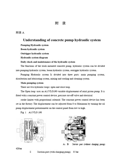
附录附录AUnderstanding of concrete pump hydraulic systemPumping Hydraulic systemBoom hydraulic systemOutrigger hydraulic systemHydraulic system diagramDaily check and maintenance of the hydraulic systemThe functions of the truck mounted concrete pump, hydraulic system can be divided into pumping hydraulic system, boom hydraulic system, outrigger hydraulic system.Pumping Hydraulic system Is divided into three parts: main pumping system, distribution and lubricating system, mixing and cooling and cleaning system.Main pumping systemThere are two hydraulic loops: open and close loop.The Open loop: uses an A11VLO190 variable displacement of axial piston pump. It is fitted with a constant power control device, pressure cut-off valve and electrical stroke limiter with proportional solenoid. The constant power control device has beenset in the factory. The displacement can be adjusted from 0 to Maximum by turning the oil pump displacement potentiometer on the control panel from low to high.Fig. 1 A11VLO 190A,B Service port (without charging pump) 420 barS Suction port (with charging pump) 35 barT1, T2 Air bleed, tankR Air bleed, oil drainM1 Measuring point, regulating chamberM Measuring point, service portG Port for positioning pressure (controller) for version with stroke limiter (H.., U2), HD and EP with screwed fitting GE10 – PLM (otherwise port G closed)The other is the control line, which can change the flow direction and the displacement of main pump through constant power valve, proportional solenoid pressure reducing valve, directional control valve and servo valve of main pump.The Closed loop: There is an auxiliary pump with relief valve that the setting pressure is 3.5Mpa in A4VG180. The auxiliary pump has two output ways. One is the charge oil line, which connects with suction line of main pump through the check valve in two pressure relief valves and add oil to main pump. At the same time excessive hydraulic oil return to oil tank through flushing valve and cooler to realize heat exchange for closed loop.A, B Service line ports SAE 1 1/4", high pressure series 420 barT1 Case drain or filling portT2 Case drain M33×2; 18 deepM A, M B Pressure gauge - operating pressure A, BR Air bleedS Boost suction portX1, X2Control pressure ports (before the orifice)G Pressure port for auxiliary circuitP S Control pressure supplyFa Filter outletFa1Filter outlet (filter assembly)Fe Filter inlet M33×2; 18 deepF S Port from filter to suction line (cold start)M H Port for balanced high pressureY1, Y2Remote control ports (only for HD control)Flushing valveUsed for closed loop to prevent excessive heat build-up in closed circuit operation. The setting pressure of flushing valve is 3.0MPaPressure reducing valve with proportional solenoidUsed for closed loop. The Output pressure is connected with the remote control port of main pump to control the displacement and is controlled by a proportional current signal and constant power valve. The displacement can be adjusted from 0 to Maximum by turning the displacement adjusting potentiometer.Constant power valveUsed for closed loop. When the hydraulic system pressure is over the setting pressure, the valve works to reduce the output pressure of the pressure reducing valve and maintain the constant power.Fig.3 Constant power valveMain pump suction filterOpen loop: filtration fineness 100u.Close loop: filtration fineness 20u.When the indicator in the vacuum gauge exceeds the safe area or the electric signal instrument gives a warning, the cartridge may be blocked. It should be clean or replace filter cartridge promptly.Filter filtration fineness is 20u in open loop. When the reading pressure of the vacuum gauge exceeds 0.35Mpa, the cartridge may be blocked. It should be clean or Return filterreplace filter cartridge promptly.Filter filtration fineness is 10u in closed loop. When the electricity deliver reports to the police, the cartridge may be blocked, it should be clean or replace filter cartridge promptly.Distribution and lubricating systemConstant pressure pumpFig.4 Constant pressure pumpAn A10VO28 constant pump is used for the distribution system of supply oil.The setting of the pressure control valve of the pump is 16Mpa. Once the system pressure is reached, the bump will keep this pressure then decrease the displacement. Thereis a pressure relief valve in the distribution circuit to act as a safety valve, which is set to 18Mpa.Plate ball valve (shut-off valve)Used to discharge the accumulator. It must be rotated the lever of shut-off valve anti-clockwise when the pumping finishes or stopped for maintenance, in order to discharge the pressure of theaccumulator. (Pressure gauge of distribution system is zero) AccumulatorInflation pressure is 8-9Mpa. Use Only Nitrogen to fill the accumulator. Charging pressure should not exceed these figures.Lubricating systemThere are two types. One is reciprocating centralized lubrication that is driven by oil from the swing cylinders of distribution system includes lubricating single pump (or double pump), distributor, damper and filter. The other is automatic centralized lubrication that is driven by a D.C motor with an independent grease tank and independent from the hydraulic system. The interval time of lubrication is carried out in the factory. The lubrication system works automatically when pumping.Mixing, cooling, cleaning systemOnly the Mixing, cooling, cleaning system are driven by motor in open loop.Gear pumpGear pump supplies oil to the mixing, cooling, cleaning system.Sandwich type relief valveThe pressure is set to 14Mpa.Ressure relayIf the mixing blade is stuck, the system pressure will raise. When the pressure exceeds the setting value (usually 10Mpa), the pressure relay will give a warning. The Solenoid directional control valve changes direction to let the mixing motor to rotate anti-clockwise. After 6 second the solenoid valve will reset, and the mixing motor will rotate clockwise again.Return filterThe filtration fineness is 10u in closed loop. The cartridge may be blocked when the electric alarm sounds. It should be replace promptly.Boom hydraulic systemBoom pumpBoom and outrigger use the same pump.37m and 40m truck mounted concrete pumps: A2FO23 fixed displacement pump44m and 47m truck mounted concrete pumps: A7VO55LRDS variable displacement pump, or A7VO55DRS variable displacement pump46m and 49m truck mounted concrete pumps: A7VO55LRDS variable displacement pumpFig.5 A7VO55DRS Fig.6 A7VO55LRDS Fig.7 A2FO23Boom proportional directional spool valveThe proportional directional spool valve with electro-hydraulic consists of pressure relief valve, pressure reducing valve, and flow control valve, and can becontrolled manual or by remote control.Fig.8 Boom proportional directional spool valveLoad-holding valveLoad-holding valve has thre e functions. (1) It acts as a lock when the cylinder isn’t moving. (2) Load-holding valve has twice relief function to protect boom against vibrating. It will be adjusted in the factory. (3) When the boom moves downward asSlewing load-holding valvegravity load, it can limit speed to prevent the boom falling too quickly and shaking.There are three main functions. Lock, overload protection and speed limiting.Outrigger hydraulic systemOutrigger hydraulic system and boom hydraulic system are used the same pump to supply oil. Outriggers should be set up before the boom is operated by the control levers or electric control button on both sides of the truck mounted concrete pump.Outrigger proportional directional spool valveIt is an integrated unit with a relief valve inside to control maximum pressure of theoutrigger hydraulic system.Fig .9 Outrigger proportional directional spool valveOutrigger hydraulic lockIt is used to lock the outrigger cylinders and pay attention to the vertical moving of the outrigger cylinder when working .Pressurerelief附录B混凝土泵车液压系统的认识泵送单元液压系统 臂架液压系统 支腿液压系统 液压原理图液压系统的日常保养及维护泵车液压系统按泵车功能可划分为泵送单元液压系统、臂架液压系统、支腿液压系统。
液压机械与液压泵外文翻译文献

液压机械与液压泵外文翻译文献液压机械与液压泵外文翻译文献(文档含中英文对照即英文原文和中文翻译)Hydraulic machinery and pumpHydraulic machinery are machines and tools which use fluid power to do work. Heavy equipment is a common example.In this type of machine, high-pressure liquid - called hydraulic fluid - is transmitted throughout the machine to various hydraulic motors and hydraulic cylinders. The fluid is controlled directly or automatically by control valves and distributed through hoses and tubes.The popularity of hydraulic machinery is due to the very large amount ofpower that can be transferred through small tubes and flexible hoses, and the high power density and wide array of actuators that can make use of this power.Hydraulic machinery is operated by the use of hydraulics, where a liquid is the powering medium. Pneumatics, on the other side, is based on the use of a gas as the medium for power transmission, generation and control.Hydraulic circuitsFor the hydraulic fluid to do work, it must flow to the actuator and or motors, then return to a reservoir.The fluid is then filtered and re-pumped. The path taken by hydraulic fluid is called a hydraulic circuit of which there are several types. Open center circuits use pumps which supply a continuous flow. The flow is returned to tank through the control valve's open center; that is, when the control valve is centered, it provides an open return path to tank and the fluid is not pumped to a high pressure. Otherwise, if the control valve is actuated it routes fluid to and from an actuator and tank. The fluid's pressure will rise to meet any resistance, since the pump has a constant output. If the pressure rises too high, fluid returns to tank through a pressure relief valve.Hydraulic pumps supply fluid to the components in the system. Pressure in the system develops in reaction to the load. Hence,a pump rated for 5,000 psi is capable of maintaining flow against a load of 5,000 psi.Pumps have a power density about ten times greater than an electric motor (by volume). They are powered by an electric motor or an engine, connected through gears, belts, or a flexible elastomeric coupling to reduce vibration.Common types of hydraulic pumps to hydraulic machinery applications are;Gear pump: cheap, durable, simple. Less efficient, because they are constant displacement, and mainly suitable for pressures below 20 MPa (3000 psi).Vane pump: cheap and simple, reliable (especially in g-rotor form). Good for higher-flow low-pressure output.Axial piston pump: many designed with a variable displacement mechanism, to vary output flow for automatic control of pressure. There are various axial piston pump designs, including swashplate and checkball. The most common is the swashplate pump.Radial piston pump: A pump that is normally used for very high pressure at small flows.Piston pumps are more expensive than gear or vane pumps, but provide longer life operating at higher pressure, with difficult fluids and longer continuous duty cycles. Pistonpumps make up one half of a hydrostatic transmission. Control valvesDirectional control valves route the fluid to the desired actuator. They usually consist of a spool inside a cast iron or steel housing.Directional control valves are usually designed to be stackable, with one valve for each hydraulic cylinder, and one fluid input supplying all the valves in the stack.The spool position may be actuated by mechanical levers, hydraulic pilot pressure, or solenoids which push the spool left or right.The main valve block is usually a stack of off the shelf directional control valves chosen by flow capacity and performance. Some valves are designed to be proportional (flow rate proportional to valve position), while others may be simply on-off. The control valve is one of the most expensive and sensitive parts of a hydraulic circuit.Pressure relief valves are used in several places in hydraulic machinery; on the return circuit to maintain a small amount of pressure for brakes, pilot lines, etc... On hydraulic cylinders, to prevent overloading and hydraulic line rupture. On the hydraulic reservoir, to maintain a small positive pressurewhich excludes moisture and contamination.Pressure reducing valves reduce the supply pressure as needed for various circuits.Check valves are one-way valves, allowing an accumulator to charge and maintain its pressure after the machine is turned off, for example.Counterbalance valves are in fact a special type of pilot controlled check valve. Whereas the check valve is open or closed, the counterbalance valve acts a bit like a pilot controlled flow control.Hydraulic pump typesGear pumpsGear pumps (with external teeth) (fixed displacement) are simple and economical pumps. The swept volume or displacement of gear pumps for hydraulics will be between about 1 cm3(0.001 litre) and 200 cm3(0.2 litre). These pumps create pressure through the meshing of the gear teeth, which forces fluid around the gears to pressurize the outlet side. Some gear pumps can be quite noisy, compared to other types, but modern gear pumps are highly reliable and much quieter than older models.Rotary vane pumpsRotary vane pumps (fixed and simple adjustable displacement) have higher efficiencies than gear pumps, but are also used for mid pressures up to 180 bars in general. Some types of vane pumps can change the centre of the vane body, so that a simple adjustable pump is obtained. These adjustable vane pumps are in general constant pressure or constant power pumps: the displacement is increased until the required pressure or power is reached and subsequently the displacement or swept volume is decreased until an equilibrium is reached.Screw pumpsScrew pumps (fixed displacement) are a double Archimedes' screw, but closed. This means that two screws are used in one body. The pumps are used for high flows and relatively low pressure (max 100 bar). They were used on board ships where the constant pressure hydraulic system was going through the whole ship, especially for the control of ball valves, but also for the steering gear and help drive systems. The advantage of the screw pumps is the low sound level of these pumps; the efficiency is not that high.Bent axis pumpsBent axis pumps, axial piston pumps and motors using the bent axis principle, fixed or adjustable displacement, exists in two different basic designs. The Thoma-principle (engineer Hans Thoma, Germany, patent 1935) with max 25 degrees angle and the Wahlmark-principle (GunnarAxel Wahlmark, patent 1960) with spherical-shaped pistons in one piece with the piston rod, piston rings, and maximum 40 degrees between the driveshaft centerline and pistons (V olvo Hydraulics Co.). These have the best efficiency of all pumps. Although in general the largest displacements are approximately one litre per revolution, if necessary a two-liter swept volume pump can be built. Often variable-displacement pumps are used, so that the oil flow can be adjusted carefully. These pumps can in general work with a working pressure of up to 350–420 bars in continuous work.Axial piston pumps swashplate principleAxial piston pumps using the swashplate principle (fixed and adjustable displacement) have a quality that is almost the same as the bent axis model. They have the advantage of being more compact in design. The pumps are easier and more economical to manufacture; the disadvantage is that they are more sensitive to oil contamination.Radial piston pumpsRadial piston pumps (fixed displacement) are used especially for high pressure and relatively small flows. Pressures of up to 650 bar are normal. In fact variable displacement is not possible, but sometimes the pump is designed in such a way that the plungers can be switched off one by one, so that a sort of variable displacement pump is obtained.Peristaltic pumpsPeristaltic pumps are not generally used for high pressures.Pumps for open and closed systemsMost pumps are working in open systems. The pump draws oil from a reservoir at atmospheric pressure. It is very important that there is no cavitation at the suction side of the pump. For this reason the connection of the suction side of the pump is larger in diameter than the connection of the pressure side. In case of the use of multi-pump assemblies, the suction connection of the pump is often combined. It is preferred to have free flow to the pump (pressure at inlet of pump at least 0.8 bars). The body of the pump is often in open connection with the suction side of the pump.In case of a closed system, both sides of the pump can be at high pressure. The reservoir is often pressurized with 6-20 bars boost pressure. For closed loop systems, normally axial piston pumps are used. Because both sides are pressurized, the body of the pump needs a separate leakage connection.Multi pump assemblyIn a hydraulic installation, one pump can serve more cylinders and motors. The problem however is that in that case a constant pressure system is required and the system always needs the full power. It is more economic to give each cylinder and motor its own pump. In that case multi pump assemblies can be used. Gearpumps can often be obtained as multi pumps.The different chambers (sometimes of different size) are mounted in one body or built together. Also vane pumps can often be obtained as a multi pump. Gerotor pumps are often supplied as multi pumps. Screw pumps can be built together with a gear pump or a vane pump. Axial piston swashplate pumps can be built together with a second pump of the same or smaller size, or can be built together with one or more gear pumps or vane pumps (depending on the supplier). Axial plunger pumps of the bent axis design can not be built together with other pumps.翻译:液压机械及泵液压机械是机械和工具,它使用流体的力量去做的工作。
液压专业毕业设计外文翻译有译文外文文献值得收藏哦

外文原文:The Analysis of Cavitation Problems in the Axial Piston Pumpshu WangEaton Corporation,14615 Lone Oak Road,Eden Prairie,MN 55344This paper discusses and analyzes the control volume of a piston bore constrained by the valve plate in axial piston pumps。
The vacuum within the piston bore caused by the rise volume needs to be compensated by the flow; otherwise, the low pressure may cause the cavitations and aerations。
In the research, the valve plate geometry can be optimized by some analytical limitations to prevent the piston pressure below the vapor pressure。
The limitations provide the design guide of the timings and overlap areas between valve plate ports and barrel kidneys to consider the cavitations and aerations。
_DOI: 10。
1115/1.4002058_ Keywords: cavitation ,optimization, valve plate,pressure undershoots 1 IntroductionIn hydrostatic machines,cavitations mean that cavities or bubbles form in the hydraulic liquid at the low pressure and collapse at the high pressure region, which causes noise,vibration,and less efficiency.Cavitations are undesirable in the pump since the shock waves formed by collapsed may be strong enough to damage components. The hydraulic fluid will vaporize when its pressure becomes too low or when the temperature is too high. In practice,a number of approaches are mostly used to deal with the problems:(1) raise the liquid level in the tank,(2)pressurize the tank, (3)booster the inlet pressure of the pump,(4) lower the pumping fluid temperature,and (5) design deliberately the pump itself.Many research efforts have been made on cavitation phenomena in hydraulic machine designs。
毕业论文中英文文献翻译液压专业毕业论文[管理资料]
![毕业论文中英文文献翻译液压专业毕业论文[管理资料]](https://img.taocdn.com/s3/m/4105879e58fafab068dc020e.png)
本科毕业论文--外文原文学院(系):年级专业:液压学生姓名:指导教师:完成日期:Why decompression is necessary in hydraulic systemsHydraulics & PneumaticsJun. 11, 2008 12:00amWhy decompression is necessary in hydraulic systemsIn high-pressure circuits with large-bore, long-stroke cylinders -- and the accompanying large pipes and/or hoses -- there is a good chance for system shock. In circuits with large components, when high-pressure oil rapidly discharges to tank, decompression shock results.Decompression shock is one of the greatest causes of damage to piping, cylinders, and valves in hydraulically powered machines. The energy released during decompression breaks pipes, blows hoses, and can instantly displace cylinder seals. Damage from decompression shock may take time to show up because the energy released by a single shock may be small. After repeated shocks however, weaker parts in the circuit start to fail.The potential for decompression shock is usually easy to determine beforehand and the design can be revised to avoid it. Shock from decompression normally occurs at the end of a pressing cycle when valves shift to stop pressing and retract the cylinder. The compressibility of the oil in the circuit, cylinder tube expansion, and the stretching of machine members -- all add to stored energy. The more energy stored, the worse the effects of decompression. Any time stored energy is a problem in a hydraulic system, a simple decompression circuit will add reliability and extend the system’s service life.One type of decompression shock that is hard to overcome occurs when a cylinder builds tonnage, then breaks through the work. Because pressure is resistance to flow, once the resistance is removed, the oil expands and decompresses rapidly. Such is the case when punching holes in a part. Punching a pplications pose one of the worse shock conditions any hydraulic circuit meets. To help reduce this type shock, keep piping as short as possible and anchor it rigidly. Some manufacturers offer resisting cylinders that slow the workingcylinder’s movement at breakthrough. These special cylinders may reduce or eliminate decompression shock.Another type of shock occurs when oil flowing at high velocity comes to a sudden stop. This might happen when a cylinder bottoms out or when a directional valve shifts to a blocked condition. Whatever the cause, the effect is the same as trying to stop a solid mass moving at high speed. Use an accumulator or deceleration valve to control shock caused by a sudden flow stop. (See Chapter 1 on accumulators.)The ensuing text describes applications where decompression shock might cause a problem. Also shown is the operation of some typical decompression circuits.When using a decompression circuit, cycle time becomes longer. Instead of the cylinder immediately retracting after finishing its working stroke, there is a short delay while stored energy dissipates. (It may be possible to arrange to decrease cylinder traverse time to make up for decompression time.) In any case, the added cycle time, if necessary, will decrease down time and maintenance problems.Press circuit without decompressionFigure 7-1 shows a schematic diagram for a typical medium- to large-bore cylinder without provision for decompression. A cylinder always needs a decompression circuit -- while cylinders with bores under 10 in. may get by without one. The main criteria are the volume and pressure of the stored fluid. The more high-pressure oil in a circuit, the greater the decompression shock. Long lengths of hose also cause and/or amplify decompression shock. It is best to install a decompression circuit when there is any chance it may be necessary. The expense of a decompression circuit is minimal and only adds to the cycle time if used.Fig. 7-1. Press circuit without decompression protection – at rest with the pumprunning.The circuit in Figure 7-1 has a directional valve with an all-ports-open center condition. The pump unloads to tank when the valve shifts to this center condition. The cylinder stays retracted because there is a counterbalance valve on the rod port.In Figure 7-2 the cylinder is pressing at a working pressure of 2800 psi. The 10-in. bore by 40-in. stroke cylinder holds approximately 3141 of oil. Added to this is another 800 of oil is in the pipe between the valve and the cylinder’s cap end. At a compressibility of approximately 1/2% per thousand psi, and allowing another 1/2% per thousand psi for physical expansion of the cylinder and pipe, plus frame stretch, total volume expansion could be up to 1% per thousand psi. Multiplying () X (2800 psi) X (3941 ) indicates that there are approximately 110 of extra oil in the cylinder when pressing at 2800 psi.Fig. 7-2. Press circuit without decompression protection – while extended cylinder is at full tonnage.When the directional valve shifts to retract the cylinder, a large portion of the 110 of extra oil rapidly flows to tank. Every corner this fast moving fluid turns and every restriction it meets causes system shock. The shock only lasts a few milliseconds during each cycle but the damage accumulates. In a small system like this one, the shock may not be audible or give a noticeable jerk to the pipes. However each shock adds to the last one, and the damage eventually shows up in leaking fittings or broken machine members.Press circuit with decompressionThe circuit depicted in Figure 7-4 is the same as in Figures 7-1, 7-2, and 7-3, but a decompression circuit has been added. Also, the directional valve’s center condition has ports P, B, and T interconnected, while port A is blocked. A pressure switch and a single-solenoid directional valve (the decompression valve)are added to the basic circuit to make decompression automatic and adjustable. The cylinder is at full tonnage in Figure 7-4, ready for decompression before beginning to retract.Fig. 7-3. Press circuit without decompression protection – cylinder just starting to retract.Fig. 7-4. Press circuit with decompression protection – while extended cylinder is at full tonnage.In this circuit, the signal to the retract solenoid on the directional valve passes through the normally closed contacts on the pressure switch. With a pressure switch setting of 350 psi, the retract solenoid will not be energized until pressure in the cap end of the cylinder lowers to that level and the contacts close. Set the shift pressure of the pressure switch high enough to shorten the decompression time as much as possible, yet still low enough to eliminate decompression shock.In Figure 7-5, the extend solenoid on the directional valve has just been deenergized, and a 115-V AC signal to retract the cylinder is on, but is blocked at the pressure switch’s open contacts. The 115-V AC signal does go to the decompression valve’s solenoid and that valve shi fts, opening a path to tank for any stored energy. Until pressure in the cap end of the cylinder deteriorates to the pressure switch setting, the cylinder sits still. The main flow of trapped oil in the cylinder is stopped at the directional valve’s blocke d A port. This part of the cycle completely eliminates all shock damage -- although it does add to cycle time.Fig. 7-5. Press circuit with decompression protection –while cylinder isdecompressing.Note the orifice in the line going to tank from the decompression directional valve. A fixed or adjustable orifice works equally well here. The orifice size determines the length of decompression time. If the orifice is too large, shock is less but may still be enough to cause damage. If the orifice is too small, there is no shock but cycle time may slow.When pressure in the cylinder’s cap end drops to the pressure switch setting -- as in Figure 7-6 -- the pressure switch shifts to its normal condition. The normally closed contacts on the pressure switch pass a signal to the retract solenoid on the directional valve, and the cylinder retracts.Fig. 7-6. Press circuit with decompression protection –while cylinder isretracting.Large press circuit with prefill valve and decompressionOn presses with large-bore cylinders or rams, oil compressibility is a problem. Another problem can be how to fill the ram as it approaches the work at high speeds and how to empty the ram when it retracts rapidly. The circuit in Figures 7-7 through 7--12 shows how to use a prefill valve to fill and empty a large ram. This type of prefill valve also can decompress the ram automatically without electrical controls.Fig. 7-7. Press circuit with prefill and decompression valves – at rest with pump running.Figure 7-7 shows the parts of a typical high-tonnage press. Small double-acting cylinders A (sometime called outriggers or pull-back cylinders) rapidly extend and retract the large ram. A small volume of oil cycles the outriggers for fast advance and return. Counterbalance valve B keeps the outriggers from running away and sequence valve C directs all fluid to the outriggers until the platen meets resistance. As the ram advances, vacuum opens prefill valve D, sucking fluid out of the tank to fill the large volume. Piloting the prefill valve open on retract first decompresses trapped oil, then allows free return flow to tank from the ram.附录四燕山大学本科毕业论文--外文译文文章名称:为什么减压在液压系统中是必要的学院(系):年级专业:液压学生姓名:指导教师:完成日期: 2013年6月13日为什么减压在液压系统中是必要的在高压油路和大缸径、长行程气缸——以及随之而来的大型管道和/或软管——很有可能对系统冲击。
机械 外文翻译 外文文献 英文文献 液压系统
机械外文翻译外文文献英文文献液压系统Hydraulic SystemHydraulic presser drive and air pressure drive hydraulic fluid asthe transmission is madeaccording to the 17th century, Pascal's principle of hydrostatic pressure to drive the development of an emerging technology, the United Kingdom in 1795 • Braman Joseph (JosephBraman ,1749-1814), in London water as a medium to form hydraulic press used in industry, the birth of the world's first hydraulic press. Media work in 1905 will be replaced by oil-water and further improved.After the World War I (1914-1918) ,because of the extensive application of hydraulic transmission, espec- ially after 1920, more rapid development. Hydraulic components in the late 19th century about the early 20th century, 20 years, only started to enter the formal phase of industrial production. 1925 Vickers (F. Vikers) the invention of the pressure balanced vane pump, hydraulic components for the modern industrial or hydraulic transmission of the gradual establishment of the foundation. The earl y 20th century G • Constantimscofluct- uations of theenergy carried out by passing theoretical and practical research; in 1910 on the hydraulic trans- mission (hydraulic coupling, hydraulic torque converter, etc.) contributions, so that these two areas ofdevelo- pment.The Second World War (1941-1945) period, in the United States 30% of machine tool applications in the hydraulic transmission. It should be noted that the development of hydraulic transmission in Japan than Europe and the United States and other countries for nearly 20 years later. Before and after in 1955, the rapid development of Japan's hydraulic drive, set up in 1956, "Hydraulic Industry." Nearly 20 to 30 years, the development of Japan's fast hydraulic transmission, a world leader.Hydraulic transmission There are many outstanding advantages, it is widely used, such as general industr- ial use of plastics processing machinery, the pressure of machinery, machine tools, etc.; operating machinery engineering machinery, construction machinery, agricultural machinery, automobiles, etc.; iron and steel indu- stry metallurgical machinery, lifting equipment, such as roller adjustment device; civil water projects with flo- od control and dam gate devices, bed lifts installations, bridges and other manipulation of institutions; speed turbine power plant installations, nuclear power plants, etc.; ship from the deck heavy machinery (winch), the bow doors, bulkhead valve, stern thruster, etc.; special antenna technology giant with control devices, measu- rement buoys, movements such as rotating stage; military-industrial control devices used in artillery, ship anti- rolling devices, aircraft simulation, aircraft retractable landing gear and ruddercontrol devices and other devi- ces.A complete hydraulic system consists of five parts, namely, power components, the implementation of co- mponents, control components, auxiliary components and hydraulic oil.一个完整的液压系统由五个部分组成,即动力元件、执行元件、控制元件、辅助元件和液压油。
DOC-机械专业毕业设计外文翻译--什么是液压-液压系统

DOC-机械专业毕业设计外文翻译--什么是液压-液压系统What is Hydraulic?A complete hydraulic system consists of five parts, namely, power components, the implementation of components, control components, no parts and hydraulic oil. The role of dynamic components of the original motive fluid into mechanical energy to the pressure that the hydraulic system of pumps, it is to power the entire hydraulic system. The structure of the form of hydraulic pump gears are generally pump, vane pump and piston pump. Implementation of components (such as hydraulic cylinders and hydraulic motors) which is the pressure of the liquid can be converted to mechanical energy to drive the load for a straight line reciprocating movement or rotational movement. Control components (that is, the various hydraulic valves) in the hydraulic system to control and regulate the pressure of liquid, flow rate and direction. According to the different control functions, hydraulic valves can be divided into the village of force control valve, flow control valves and directional control valve. Pressure control valves are divided into benefits flow valve (safety valve), pressure relief valve, sequence valve, pressure relays, etc.; flow control valves including throttle, adjusting the valves, flow diversion valve sets, etc.; directional control valve includes a one-way valve , one-way fluid control valve, shuttle valve, valve and so on. Under the control of different ways, can be dividedinto the hydraulic valve control switch valve, control valve and set thevalue of the ratio control valve. Auxiliary components, including fuel tanks, oil filters, tubing and pipe joints, seals, pressure gauge, oil level, such as oildollars. Hydraulic oil in the hydraulic system is the work of the energy transfer medium, there are a variety of mineral oil, emulsion oil hydraulic molding Hop categories.Hydraulic principleIt consists of two cylinders of different sizes and composition of fluid in the fluid full of water or oil. Water is called "hydraulic press"; the said oil-filled "hydraulic machine." Each of the two liquida sliding piston, if the increase in the small piston on the pressure of a certain value, according to Pascal's law, small piston to the pressure of the pressure through the liquid passed to the large piston, pistontop will go a long way to go. Based cross-sectional area of the small piston is S1, plus a small piston in the downward pressure on the F1. Thus, a small piston on the liquid pressure to P = F1/SI, Can be the same size in all directions to the transmission of liquid. "By the large piston is also equivalent to the inevitable pressure P. If the large piston is the cross-sectional area S2, the pressure P on the piston in the upward pressure generated F2 = PxS2Cross-sectional area is a small multiple of the piston cross-sectional area. From the type known to add in a small piston of asmaller force, the piston will be in great force, for which thehydraulic machine used to suppress plywood, oil, extract heavy objects, such as forging steel.History of the development of hydraulicAnd air pressure drive hydraulic fluid as the transmission is made according to the 17th century, Pascal's principle of hydrostatic pressure to drive the development of an emerging technology, the United Kingdom in 1795 Joseph (Joseph Braman ,1749-1814), in London water as a medium to form hydraulic press used in industry, the birth of theworld's first hydraulic press. Media work in 1905 will be replaced byoil-water and further improved.World War I (1914-1918) after the extensive application of hydraulic transmission, especially after 1920, more rapid development. Hydraulic components in the late 19th century about the early 20th century, 20 years, only started to enter the formal phase of industrial production. 1925 Vickers (F. Vikers) the invention of the pressure balanced vane pump, hydraulic components for the modern industrial or hydraulic transmission of the gradual establishment of the foundation. The early 20th century Constantine (G • Constantimsco) fluctuations of the ener gy carried out by passing theoretical and practical research; in 1910 on the hydraulic transmission (hydraulic coupling, hydraulic torque converter, etc.) contributions, so that these two areas of development.The Second World War (1941-1945) period, in the United States 30% of machine tool applications in the hydraulic transmission. It should be noted that the development of hydraulic transmission in Japan thanEurope and the United States and other countries for nearly 20 years later. Before and after in1955, the rapid development of Japan's hydraulic drive, set up in 1956, "Hydraulic Industry." Nearly 20 to 30 years, the development of Japan's fast hydraulic transmission, a world leader.Hydraulic transmission There are many outstanding advantages, it is widely used, such as general workers. Plastic processing industry, machinery, pressure machinery, machine tools, etc.; operating machinery engineering machinery, construction machinery, agricultural machinery, automobiles, etc.; iron and steel industry metallurgical machinery, lifting equipment, such as roller adjustment device; civil waterprojects with flood control the dam gates and devices, bed lifts installations, bridges and other manipulation of institutions; speed turbine power plant installations, nuclear power plants, etc.; ship deck crane (winch), the bow doors, bulkhead valves, such as the sternthruster ; special antenna technology giant with control devices, measurement buoys, movements such as rotating stage; military-industrial control devices used in artillery, ship anti-rolling devices, aircraft simulation, aircraft retractable landing gear and rudder control devices and other devices.什么是液压,一个完整的液压系统由五个部分组成,即动力元件、执行元件、控制元件、无件和液压油。
机械外文翻译文献翻译液压系统1
外文原文:Theory of fluid propertiesWe will concentrate mainly on three fluid properties in this chapter:• The density which leads to mass and hence to hydraulic inertia effects.• The viscosity which leads to the hydraulic friction effects.• The compressi bility and thus the bulk modulus which leads to the hydraulic system stiffness. Notice that the compressibility effect can be modified by air release, cavitation phenomena and by expansion of a pipe, hose or chamber containing the hydraulic fluid.1 Density and compressibility coefficientThe density is the mass of a substance per unit volume:Density has dimensions of [M/L3] and is expressed in kilograms per cubic meter [kg/m3]. As mentioned previously the density is a function of the pressure and the temperature:This function can be approximated by the first three terms of a Taylor series:This can also be expressed as:WithAndThis equation is the linearized state equation for a liquid. Using the definition of thedensity, the two coefficients α and B can also be expressed as:B is known as the isothermal bulk modulus or for simplicity the bulk modulus and α is known as the cubical expansion coefficient. Since fluid density varies with the applied pressure, this implies that a given mass of fluid submitted to a pressure change changes its volume. This phenomenon leads to the definition of the compressibility coefficient β:where β is expressed in units Pa 1 (or m2/N). Considering the relation for a closed hydraulic circuit the mass is constant, and hence:it follows thatUsing the definition of the compressibility coefficient β we obtain:More usually we use the bulk modulus B also known as the volumetric elasticity modulus:The relation between ρ and B implies mass conservation. This relation must be RIGOROUSLY RESPECTED in the calculations. In the modeling and simulation context of fluid energy systems, disregarding the relation between ρ and B leads to abnormal evolutions of pressure in the closed circuit submitted to compression and expansion cycles. This phenomenon is strongly accentuated if aeration occurs in the circuit (when dissolved air in the fluid reappears in the form of bubbles). We shall approach this point by examining the phenomena of aeration and cavitation. The aircan also have adverse consequences on a fluid compressibility. In liquid air can be present in two forms: entrapped and dissolved.Entrapped airWhen the return pipe is not submersed in the tank the liquid jet can entrain some air bubbles in the tank. Another phenomenon that affects the quantity of air in liquid is the leakage.Figure 1: Liquid leakageFigure 2: Air is entrainedThis air stays in the liquid as cavities and can modify the fluid compressibility. In this context we talk about effective bulk modulus. Figure 3 shows the bulk modulus of a diesel fuel at 40 °C with 0, 0.01, 0.1, 1, 10% air. The plot is obtained using the system shown. The model of the diesel fuel properties is based on accurate ex-perimental measurements and are designed for use with injection system which are very fast acting. For this reason air is assumed to be entrained rather than dissolved.Figure 3Dissolved airAir can also be dissolved in a liquid. A certain amount of air molecule can be part of the liquid. In this case the dissolved air does not significantly change the fluid properties.2 Air release and cavitationAir can be dissolved or entrained in liquids and it is possible for air to change from one of these two forms to the other depending on the conditions to which the fluid is subjected.Suppose the fluid is in equilibrium with a certain percentage of dissolved gas (usually air: nitrogen and oxygen). Lowering the pressure above a critical value called the saturation pressure induces aeration. This is the process where the dissolved gas forms air bubbles in the liquid until all the dissolved gases or air are free.The exact point where all the dissolved gas has come out of solution is difficult to pin-point because it depends on the chemical composition and behavior of the gas. This is a non-symmetrical dynamic process: the growing process does not have the same dynamics as when air bubbles disappear. In consequence the total amount of bubbles created when the pressure drops may or may not be redissolved in the liquid when it rises again.If the pressure is dropped further and above another critical value called the vapor pres s ure, the fluid itself starts to vaporize. It corresponds to a liquid phase change. At some point only fluid vapor and gas exist. In liquid systems the term cavitation usually refers to the formation and collapse of cavities in the liquid even if cavities contain air or liquid vapor.To summarize with a sketch what we have introduced see above:Figure 4: Air release and cavitationThe development of a cavity is now recognized as being associated with a nucleation center such as microscopic gas particles, wear or wall asperities. When the liquid is subjected to a tensile stress, cavities do not form as a result of liquid rupture but are caused by the rapid growth of these nuclei.To understand this, think of beer (or champagne if you prefer) in a bottle, when it is closed you see no air bubbles and the liquid does not look fizzy. The pressure in the bottle is above the saturation pressure of the gas in the liquid. When you open the bottle suddenly bubbles appear and so the dissolved gas (molecules of gas held in the liquid) starts to appear as gas.In fact the liquid is gas saturated and the atmospheric pressure is less than the saturation pressure of the liquid. This phenomenon is clearly not cavitation but air release (aeration). Considering nuclei effects, bubbles form only at particular places in your glass: around the glass (due to small asperities) and round any particles present in the liquid. Theoretically, if your liquid was perfectly pure and the wall of the system perfectly regular, air release or cavitation would occur with great difficulty! The key point about cavitation is that it is a phase change: the liquid changes to vapor.A comparison can be made between cavitation and boiling. If we look at the phasediagram below:Figure 5: Cavitation and boilingBoiling is a phase change at constant pressure and variable temperature and cavitation is a phase change at constant temperature and variable pressure.In any system air release starts first and if the pressure decreases further, cavitation may occur. This means that, sometimes, people talk about cavitation when the real phenomenon is air release. Both phenomena can lead to destruction of the material or component.In both cases it is entrained gas that causes the troubles. When cavities encounter high pressure in the downstream circuit, these bubbles or cavities can be unstable and can collapse implosively. The pressure developed at collapse can be large enough to cause severe mechanical damage in the containing vessel. It is well-known that hydraulic pumps and pipework can be badly damaged by cavitaton and air release.In all classical hydraulic systems air release and cavitation must be avoided to prevent material destruction but sometimes it is required like for injection systems to prepare the spray formation.3 ViscosityViscosity is a measure of the resistance of the fluid to flow. This characteristic has both positive and negative effects on fluid power systems. A low viscosity leads to oil leaks in the dead zone formed between the mechanical parts in movement, and a high viscosity will lead to loss of pressure in hydraulic ducts.Viscosity is a characteristic of liquids and gases and is manifested in motion throughinternal damping. Viscosity results from an exchange of momentum by molecular diffusion between two layers of fluid with different velocities. In this sense, the viscosity is a fluid property and not a flow property.Figure 6: ViscosityFigure 6 shows the relation between shearing constraint and difference of flow velocity between two layers .The definition of viscosity was first given by Newton. Between two layers of distance dy, the exerted force between these two layers is given by:where U(y) is the velocity depending on the radial position y and dU/dy the velocity gradient. This proportionality expresses the notion of Newtonian fluid and allows the introduction of μ defined as the dynamic viscosity or the absolute viscosity.The dimension of μ is [ML1-T 1-] and the SI unit is kg/m/s or Pa s. The older unit is the Poise, P, which is 0.1 kg/m/s. However, this is very small and hence the milli Poise, mP, is the common unit which is 10-4 kg/m/s.The dynamic viscosity is the constant of proportionality between a stress and the intensity of shearing between two neighboring layers:However the absolute viscosity is not very often used in fundamental equations. For example the dynamics of the elementary volume between the two layers is expressedas:and thus using the shear stress calculation:In other formulas (e.g. Navier Stokes) the ratio between the absolute viscosity and the density occurs so often that a new parameter called the kinematic viscosity ν is introduced .of dimension [L2T 1-] and so the SI unit is the m2/s. The older unit of kinematic viscosity is the Stoke, St, which is 104-m2/s. However, even this is a very small unit and hence the centistoke cSt is the common unit with 1 cSt = 106-m2/s. This parameter is easily measured with viscometers.Note that the viscosity varies significantly with the fluid temperature.Figure 7: Viscosity against temperatureNormally in absence of air release and cavitation the variation with pressure is not great unless the pressure is very extreme.Figure 8: Variation with pressureViscosity influence on the flowAnother important aspect of the viscosity is its influence on the flow conditions of the fluid. We can distinguish two types of flow conditions:• Laminar flow for which the flow lines are parallel and shearing forces create a pressure drop.• Turbulent flow for which the fluid particles have a disordered, random movement leading to a loss of pressure.These two conditions can be distinguished using the Reynolds number which is defined as follows:WithU: average fluid velocityd: diameter of the duct (hydraulic diameter for others geometries)ρ: densityμ: dynamic viscosityν: kinematic viscosityThe transition between laminar to turbulent flow occurs at the critical Reynolds number. This is not well defined, there exists always a transition region. In a hydraulic line, the critical Reynolds number is generally between 1500 to 2000. For uneven geometries (thin-walled orifices), the critical Reynolds number can be lower than 100. For non-circular cross sections, the hydraulic diameter can be used to determine the Reynolds number. Hydraulic diameter is defined as follows:We now give one example:• Circular orifice of diameter:Flow through orificesOrifices (also called restrictions) can be fixed or variable and occur in huge numbers in fluid systems. Not surprisingly in Engineering courses a mathematical description is presented. This is usually based on Bernoulli’s equation and leads to the formwhere Cq is the flow coefficient. This is variously described as typically 0.7 or varying with orifice geometry and Reynolds number.The second alternative is obviously more correct. If we do take a constant value, we are forced to have the gradient of Q against infinity at the origin! This cannot be and if you try to implement it is a numerical disaster! Clearly the flow is laminar for sufficiently small pressure drops which means that Cq is certainly not constant. One solution is to perform detailed e xperiments and compute Cq against Reynold’s number. In the context of the orifice (not necessarily circular) the Reynold’s number iswhere U is a mean velocity and dh the hydraulic diameter. If we take U=Q/A, we end up with the form Cq =f(Q) and ultimately withIt is possible to work with an implicit relationship like this but we would prefer an explicit formula.This is provided by introducing another dimensionless number known as the flow number and denoted by λ. This is defined asFrom a modelin g point of view λ contains quantities we know. Using λ we haveand provided we have,we have an explicit relationship which is easy to evaluate. There are no more problems to obtain measurements forthan forand so the flow number form has many advantages.References :[1] McCloy D, Discharge Characteristics of Servo Valve Orifices, 1968 Fluid International Conference.[2] R.C. Binder, “Fluid Mechanics”. 3rd Edition, 3rd Printing. Prentice-Hall, Inc., Englewood Cliffs,NJ. 1956.译文:液压油理论我们将在本章主要讨论液压油的三个特性:•密度(使油液具有质量和液感效应);•粘性(使油液具有液阻效应);•可压缩性和体积弹性模量(使油液具有容性效应),值得提醒的是容性效应会受油液中析出的空气、气穴现象和装有油液的的管道、软管或油腔的影响。
机械毕业设计英文外文翻译201混凝土运输车中液压泵压力的影响 (2)
附录AInvestigation on Pressure Impact in ConcretePumping Hydraulic SystemAbstract:The pressure impact in hydraulic systems of such concrete pumping machinery as trailer concrete pump,transported concrete pump,and truck mounted concrete pump,is a key factor affecting their reliability and usage life.Based on the pressure forming principle of the oil in a hydrostatic closed pressure chamber,the mechanism of producing pressure impact is analyzed synthetically,and the theory that oil flow matches requirement,and pump displacement control harmonizes valve shifting time control,to mitigate pressure impact,is put forward.The quantitative controlling parameters about shifting time and displacement control are introduced to realize accurate control.The experiment investigations of pressure impact property and its control are carried through on an experimental system which is able to simulate concrete pumping condition.The basic law that pressure impact and controlling parameters vary with working condition respectively.The feasibility and validity of the technology proposed in this paper to control pressure impact are confirmed.Keywords: Pressure impact;Hydraulic system;Concrete pumping machinery.1 IntroductionDuring working process of such concrete machinery as trailer concrete pump,transported concrete pump,and truck mounted concrete pump,two oil cylinders drive two concrete delivery cylinders respectively,and quickly switch direction with the possible highest frequency of more than 30 times per minute,which generates serious hydraulic impact.It is an important factor resulting in bad performance and low use reliability of the machine,and vibration,noise and overheating etc.so it’s a key of improving concrete pumping machinery’s reliability to gain a mastery of pressure impact property in concrete pumping hydraulic system and its controlling technology.Such technological measures as follows were taken to reduce pressure impact:(1)installation of a hydraulic accumulator or unloading valves,(2) change of sliding spool’s structure,(3)control of the switching speed of sliding spool,etc[1].Though these measures play an important role in absorption of pressure surges,there are obvious limitations,and they are passive measures.Literature.2. investigated the switching process of concrete pumping hydraulic system,and put forward active measure of regulating oil pump’s displacement to reduce pressureimpact.Literature[3]studied the intrinsic relationship between shifting time and pressure impact,and proposed a new concept of optimal shifting time.Therefore,in this paper, experiments were conducted to find out pressure impact forming law,and both oil pump’s displacement and directional—control valve’s shifting time were controlled simultaneously to seek optimal control scheme for effective reduction of pressure impact.2 Experimental principleThe pressure variation of the oil in a pressure chamber depends upon the difference between volumes of the oil flowing in and out the chamber[2].It’s obvious that effective reduction of this difference is of positive significance for depressing pressure impact.As far as concrete pumping hydraulic system is concerned, the pressure impact resulting from the main oil cylinders’stroke terminal lies upon the suitability of shifting time to a great extent[3].So it’s feasible and effective for absorbing pressure impact to accurately control oil pump’s displacement according to hydraulic system’s requirement,and combine it with shifting time control technique.What is shown in Fig.1 is the principle drawing of the experimental system sued to study characteristics of pressure impact in concrete pumping hydraulic system and its controlling techniques.The main oil pump(1)is a swash-plate type axial piston pump,which is provided with the function of constant horsepower control。
液压系统外文文献翻译中英文

外文文献翻译(含:英文原文及中文译文)英文原文Hydraulic systemW Arnold1 IntroductionThe hydraulic station is called a hydraulic pump station and is an independent hydraulic device. It is step by step to supply oil. And control the direction of hydraulic oil flow, pressure and flow, suitable for the host and hydraulic equipment can be separated on the various hydraulic machinery.After the purchase, the user only needs to connect the hydraulic station and the actuator (hydraulic or oil motor) on the mainframe with different tubings. The hydraulic machine can realize various specified actions and working cycles.The hydraulic station is a combination of manifolds, pump units or valve assemblies, electrical boxes, and tank electrical boxes. Each part function is:The pump unit is equipped with a motor and an oil pump, which is the power source of the hydraulic station and can convert mechanical energy into hydraulic oil pressure energy.V alve combination - its plate valve is mounted on the vertical plate, and the rear plate is connected with the same function as the manifold.Oil manifolds - assembled from hydraulic valves and channel bodies. It regulates hydraulic oil pressure, direction and flow.Box--a semi-closed container for plate welding. It is also equipped with an oil screen, an air filter, etc., which is used for cooling and filtering of oil and oil.Electrical box - divided into two types: one is to set the external lead terminal board; one is equipped with a full set of control appliances.The working principle of the hydraulic station: The motor drives the oil pump to rotate, then the pump sucks oil from the oil tank and supplies oil, converts the mechanical energy into hydraulic pressure energy, and the hydraulic oil passes through the manifold (or valve assembly) to adjust the direction, pressure and flow and then passes through the external tube. The way to the hydraulic cylinder or oil motor in the hydraulic machinery, so as to control the direction of the hydraulic motor, the strength of the speed and speed, to promote all kinds of hydraulic machinery to do work.(1) Development history of hydraulic pressureThe development history of hydraulics (including hydraulic power, the same below), pneumatics, and seals industry in China can be roughly divided into three stages, namely: the starting stage in the early 1950s to the early 60s; and the professional in the 60s and 70s. The growth stage of the production system; the 80-90's is a stage of rapid development. Among them, the hydraulic industry began in the early 1950s with thedevelopment of hydraulic machines such as Grinding Machines, broaching machines, and profiling lathes, which were produced by the machine tool industry. The hydraulic components were produced by the hydraulic workshop in the machine tool factory, and were produced for self use. After entering the 1960s, the application of hydraulic technology was gradually promoted from the machine tool to the agricultural machinery and engineering machinery. The original hydraulic workshop attached to the main engine plant was independent and became a professional manufacturer of hydraulic components. In the late 1960s and early 1970s, with the continuous development of mechanization of production, particularly in the provision of highly efficient and automated equipment for the second automobile manufacturing plant, the hydraulic component manufacturing industry witnessed rapid development. The batch of small and medium-sized enterprises also began to become specialized manufacturers of hydraulic parts. In 1968, the annual output of hydraulic components in China was close to 200,000 pieces. In 1973, in the fields of machine tools, agricultural machinery, construction machinery and other industries, the professional factory for the production of hydraulic parts has grown to over 100, and its annual output exceeds 1 million pieces. Such an independent hydraulic component manufacturing industry has taken shape. At this time, the hydraulic product has evolved from the original imitation Su product intoa combination of imported technology and self-designed products. The pressure has been developed towards medium and high pressures, and electro-hydraulic servo valves and systems have been developed. The application of hydraulics has been further expanded. The pneumatic industry started a few years later than hydraulics, and it was only in 1967 that it began to establish a professional pneumatic components factory. Pneumatic components began to be manufactured and sold as commodities. Its sealing industry including rubber seals, flexible graphite seals, and mechanical seals started from the production of common O-rings, oil seals, and other extruded rubber seals and asbestos seal products in the early 1950s. In the early 1960s, it began to develop and produce flexible products. Graphite seals and mechanical seals and other products. In the 1970s, a batch of batches of professional production plants began to be established one after another in the systems of the former Ministry of Combustion, the Ministry of Agriculture, and the Ministry of Agricultural Machinery, formally forming the industry, which laid the foundation for the development of the seal industry.In the 1980s, under the guidance of the national policy of reform and opening up, with the continuous development of the machinery industry, the contradiction between the basic components lags behind the host computer has become increasingly prominent and caused the attention of all relevant departments. To this end, the former Ministry of Machinesestablished the General Infrastructure Industry Bureau in 1982, and unified the original pneumatic, hydraulic, and seal specialties that were scattered in the industries of machine tools, agricultural machinery, and construction machinery, etc. The management of a piece of office, so that the industry in the planning, investment, the introduction of technology and scientific research and development and other aspects of the basic parts of the bureau's guidance and support. This has entered a period of rapid development, it has introduced more than 60 foreign advanced technology, of which more than 40 hydraulic, pneumatic 7, after digestion and absorption and technological transformation, are now mass production, and has become the industry's leading products . In recent years, the industry has intensified its technological transformation. From 1991 to 1998, the total investment of national, local, and corporate self-raised funds totaled about 2 billion yuan, of which more than 1.6 billion were hydraulic. After continuous technological transformation and technological breakthroughs, the technical level of a group of major enterprises has been further improved, and technological equipment has also been greatly improved, laying a good foundation for forming a high starting point, specialization, and mass production. In recent years, under the guidance of the principle of common development of multiple ownership systems in the country, various small and medium-sized enterprises with different ownership have rapidly emerged and haveshown great vitality. With the further opening up of the country, foreign-funded enterprises have developed rapidly, which plays an important role in raising industry standards and expanding exports. So far China has established joint ventures with famous manufacturers in the United States, Germany, Japan and other countries or directly established piston pumps/motors, planetary speed reducers, hydraulic control valves, steering gears, hydraulic systems, hydrostatic transmissions, and hydraulic components. The company has more than 50 manufacturing enterprises such as castings, pneumatic control valves, cylinders, gas processing triplets, rubber seals, and mechanical seals, and has attracted more than 200 million U.S. dollars in foreign capital.(2) Current statusBasic profileAfter more than 40 years of hard work, China's hydraulics, pneumatics and seals industry has formed a complete industrial system with a certain level of production capacity and technical level. According to the statistics of the third n ational industrial census in 1995, China’s state-owned, privately-owned, cooperative, village-run, individual, and “funded enterprises” have annual sales income of more than 1 million yuan in hydraulic, pneumatic, and seal industrial townships and above. There are a total of more than 1,300 companies, including about 700 hydraulics, and about 300 pneumatic and sealing parts. According to thestatistics of the international industry in 1996, the total output value of the hydraulic industry in China was about 2.448 billion yuan, accounting for the 6th in the world; the total output value of the pneumatic industry was about 419 million yuan, accounting for the world’s10 people.2. Current supply and demand profileWith the introduction of technology, independent development and technological transformation, the technical level of the first batch of high-pressure plunger pumps, vane pumps, gear pumps, general hydraulic valves, oil cylinders, oil-free pneumatic components and various types of seals has become remarkable. Improve, and can be stable mass production, provide guarantees for all types of host to improve product quality. In addition, certain achievements have also been made in the aspects of CAD, pollution control, and proportional servo technology for hydraulic pneumatic components and systems, and have been used for production. So far, the hydraulic, pneumatic and seal products have a total of about 3,000 varieties and more than 23,000 specifications. Among them, there are about 1,200 types of hydraulic pressure, more than 10,000 specifications (including 60 types of hydrodynamic products, 500 specifications); about 1350 types of pneumatic, more than 8,000 specifications; there are also 350 types of rubber seals, more than 5000 The specifications are now basically able to adapt to the general needs ofvarious types of mainframe products. The matching rate for major equipment sets can reach more than 60%, and a small amount of exports has started.In 1998, the domestic production of hydraulic components was 4.8 million pieces, with sales of about 2.8 billion yuan (of which mechanical systems accounted for 70%); output of pneumatic components was 3.6 million pieces, and sales were about 550 million yuan (including mechanical systems accounting for about 60%) The production of seals is about 800 million pieces, and the sales volume is about 1 billion yuan (including about 50% of mechanical systems). According to the statistics of the annual report of the China Hydraulic and Pneumatic Sealing Industry Association in 1998, the production and sales rate of hydraulic products was 97.5% (101% of hydraulic power), 95.9% of air pressure, and 98.7% of seal. This fully reflects the basic convergence of production and sales.Although China's hydraulic, pneumatic and sealing industries have made great progress, there are still many gaps compared with the development needs of the mainframe and the world's advanced level, which are mainly reflected in the variety, performance and reliability of products. . Take hydraulic products as an example, the product varieties are only 1/3 of the foreign country, and the life expectancy is 1/2 of that of foreign countries. In order to meet the needs of key hosts, imported hosts, and majortechnical equipment, China has a large number of imported hydraulic, pneumatic, and sealing products every year. According to customs statistics and relevant data analysis, in 1998, the import volume of hydraulic, pneumatic and seal products was about 200 million U.S. dollars, of which the hydraulic pressure was about 140 million U.S. dollars, the pneumatics were 30 million U.S. dollars, and the seal was about 0.3 billion U.S. dollars. The year is slightly lower. In terms of amount, the current domestic market share of imported products is about 30%. In 1998, the total demand for hydraulic parts in the domestic market was about 6 million pieces, and the total sales volume was 4 billion yuan; the total demand for pneumatic parts was about 5 million pieces, and the total sales volume was over 700 million yuan; the total demand for seals was about 1.1 billion yuan. Pieces, total sales of about 1.3 billion yuan. (3) Future developments1. The main factors affecting development(1) The company's product development capability is not strong, and the level and speed of technology development can not fully meet the current needs for advanced mainframe products, major technical equipment and imported equipment and maintenance;(2) Many companies have lagged behind in manufacturing process, equipment level and management level, and their sense of quality is not strong, resulting in low level of product performance, unstable quality,poor reliability, and insufficiency of service, and lack of user satisfaction. And trusted branded products;(3) The degree of professional specialization in the industry is low, the power is scattered, the duplication of the low level is serious, the product convergence between the region and the enterprise leads to blind competition, and the prices are reduced each other, thus the efficiency of the enterprise is reduced, the funds are lacking, and the turnover is difficult. Insufficient investment in development and technological transformation has severely restricted the overall level of the industry and its competitive strength.(4) When the degree of internationalization of the domestic market is increasing, foreign companies have gradually entered the Chinese market to participate in competition, coupled with the rise of domestic private, cooperative, foreign-funded, and individual enterprises, resulting in increasing impact on state-owned enterprises. .2. Development trendWith the continuous deepening of the socialist market economy, the relationship between supply and demand in the hydraulic, pneumatic and sealed products has undergone major changes. The seller market characterized by “shortage” has basically become a buyer’s market characterized by “structured surplus”. Replaced by. From the perspective of overall capacity, it is already in a trend of oversupply, and in particular,general low-grade hydraulic, pneumatic and seals are generally oversupply; and like high-tech products with high technological content and high value and high value-added products that are urgently needed by the host, Can not meet the needs of the market, can only rely on imports. After China's entry into the WTO, its impact may be greater. Therefore, during the “10th Five-Y ear Plan” period, the growth of the industry’s output value must not only rely on the growth of quantity. Instead, it should focus on the structural contradiction of the industry and intensify efforts to adjust the industrial structure and product structure. It should be based on the improvement of quality. Product technology upgrades in order to adapt to and stimulate market demand, and seek greater development.2. Hydraulic application on power slide(1) Introduction of Power Sliding TableUsing the binding force curve diagram and the state space analysis method to analyze and study the sliding effect and the smoothness of the sliding table of the combined machine tool, the dynamics of the hydraulic drive system of the sliding table—the self-regulating back pressure regulating system are established. mathematical model. Through the digital simulation system of the computer, the causes and main influencing factors of the slide impact and the motion instability are analyzed. What kind of conclusions can be drawn from those, if we canreasonably design the structural dimensions of hydraulic cylinders and self-regulating back pressure regulators ——The symbols used in the text are as follows:s 1 - flow source, that is, the flow rate of the governor valve outlet;S el —— sliding friction of the sliding table;R - the equivalent viscous friction coefficient of the slide;I 1 - quality of slides and cylinders;12 - self-adjusting back pressure valve core quality;C 1, c 2 - liquid volume without cylinder chamber and rod chamber;C 2 - Self-adjusting back pressure valve spring compliance;R 1, R2 - Self-adjusting back pressure valve damping orifice fluid resistance;R 9 - Self-adjusting back pressure valve valve fluid resistance;S e2——initial pre-tightening force of self-adjusting back pressure valve spring;I 4, I5 - Equivalent liquid sense of the pipeline;C 5, C 6 - equivalent liquid capacity of the pipeline;R 5, R7 - Equivalent liquid resistance of the pipeline;V 3, V4 - cylinder rodless cavity and rod cavity volume;P 3, P4—pressure of the rodless cavity and rod cavity of the cylinder;F - the slide bears the load;V - speed of slide motion;In this paper, the power bond diagram and the state space splitting method are used to establish the system's motion mathematical model, and the dynamic characteristics of the slide table can be significantly improved.In the normal operation of the combined machine tool, the magnitude of the speed of the slide, its direction and the load changes it undergoes will affect its performance in varying degrees. Especially in the process of work-in-process, the unsteady movement caused by the advancing of the load on the slide table and the cyclical change of the load will affect the surface quality of the workpiece to be machined. In severe cases, the tool will break. According to the requirements of the Dalian Machine Tool Plant, the author used the binding force curve diagram and the state space analysis method to establish a dynamic mathematical model of a self-adjusting back pressure and speed adjustment system for the new hydraulic drive system of the combined machine tool slide. In order to improve the dynamic characteristics of the sliding table, it is necessary to analyze the causes and main influencing factors of the impetus and movement of the sliding table. However, it must pass the computer's digital simulation and the final results obtained from the research.(2) Dynamic Mathematical ModelThe working principle diagram of the self-adjusting back pressure speedregulation system of the combined machine tool slide hydraulic drive system is shown in the figure. This system is used to complete the work-cycle-stop-rewind. When the sliding table is working, the three-position four-way reversing valve is in the illustrated position. The oil supply pressure of the oil pump will remain approximately constant under the effective action of the overflow valve, and the oil flow passes through the reversing valve and adjusts the speed. The valve enters the rodless chamber of the cylinder to push the slide forward. At the same time, the pressurized oil discharged from the rod chamber of the cylinder will flow back to the tank through the self-regulating back pressure valve and the reversing valve. During this process, there was no change in the operating status of both the one-way valve and the relief valve. The complex and nonlinear system of the hydraulic drive system of the self-adjusting back pressure governor system is a kind of self-adjusting back-pressure governor system. To facilitate the study of its dynamic characteristics, a simple and reasonable dynamic mathematical model that only considers the main influencing factors is established. Especially important [1][2]. From the theoretical analysis and the experimental study, we can see that the system process time is much longer than the process time of the speed control valve. When the effective pressure bearing area of the rodless cavity of the fuel tank is large, the flow rate at the outlet of the speed control valve is instantaneous. The overshoot is reflected in thesmall change in speed of the slide motion [2]. In order to further broaden and deeply study the dynamic characteristics of the system so that the research work can be effectively performed on a miniature computer, this article will further simplify the original model [2], assuming that the speed control valve is output during the entire system pass. When the flow is constant, this is considered to be the source of the flow. The schematic diagram of the dynamic model structure of this system is shown in Fig. 2. It consists of a cylinder, a sliding table, a self-adjusting back pressure valve, and a connecting pipe.The power bond graph is a power flow graph. It is based on the transmission mode of the system energy, based on the actual structure, and uses the centralized parameters to represent the role of the subsystems abstractly as a resistive element R, a perceptual element I, and a capacitive element. Three kinds of role of C. Using this method, the physical concept of modeling is clear, and combined with the state-space analysis method, the linear system can be described and analyzed more accurately. This method is an effective method to study the dynamic characteristics of complex nonlinear systems in the time domain. According to the main characteristics of each component of the self-adjusting back pressure control system and the modeling rules [1], the power bond diagram of the system is obtained. The upper half of each key in the figure represents the power flow. The two variables that makeup the power are the force variables (oil pressure P and force F) and the flow variables (flow q and velocity v). The O node indicates that the system is connected in parallel, and the force variables on each key are equal and the sum of the flow variables is zero; 1 The nodes represent the series connection in the system, the flow variables on each key are equal and the sum of the force variables is Zero. TF denotes a transformer between different energy forms. The TF subscripted letter represents the conversion ratio of the flow variable or the force variable. The short bar on the key indicates the causal relationship between the two variables on the key. The full arrow indicates the control relationship. There are integral or differential relationships between the force and flow variables of the capacitive and perceptual elements in the three types of action elements. Therefore, a complex nonlinear equation of state with nine state variables can be derived from Fig. 3 . In this paper, the research on the dynamic characteristics of the sliding table starts from the two aspects of the slide's hedging and the smoothness of the motion. The fourth-order fixed-length Runge-Kutta is used for digital simulation on the IBM-PC microcomputer.(3) Slide advanceThe swaying phenomenon of the slide table is caused by the sudden disappearance of the load acting on the slide table (such as drilling work conditions). In this process, the table load F, the moving speed V, and thepressure in the two chambers of the cylinder P3 and P4 can be seen from the simulation results in Fig. 4. When the sliding table moves at a uniform speed under the load, the oil pressure in the rodless cavity of the oil cylinder is high, and a large amount of energy is accumulated in the oil. When the load suddenly disappears, the oil pressure of the cavity is rapidly reduced, and the oil is rapidly reduced. When the high-pressure state is transferred to the low-pressure state, a lot of energy is released to the system, resulting in a high-speed forward impact of the slide. However, the front slide of the sliding table causes the pressure in the rod cavity of the oil cylinder to cause the back pressure to rise, thereby consuming part of the energy in the system, which has a certain effect on the kicking of the slide table. We should see that in the studied system, the inlet pressure of the self-adjusting back pressure valve is subject to the comprehensive effect of the two-chamber oil pressure of the oil cylinder. When the load suddenly disappears, the pressure of the self-adjusting back pressure valve rapidly rises and stably exceeds the initial back pressure value. It can be seen from the figure that self-adjusting back pressure in the speed control system when the load disappears, the back pressure of the cylinder rises more than the traditional speed control system, so the oil in the rod cavity of the cylinder absorbs more energy, resulting in the amount of forward momentum of the slide It will be about 20% smaller than traditionalspeed control systems. It can be seen from this that the use of self-adjusting back-gear speed control system as a drive system slider has good characteristics in suppressing the forward punch, in which the self-adjusting back pressure valve plays a very large role.(4) The smoothness of the slideWhen the load acting on the slide changes periodically (such as in the case of milling), the speed of the slide will have to fluctuate. In order to ensure the processing quality requirements, it must reduce its speed fluctuation range as much as possible. From the perspective of the convenience of the discussion of the problem, assume that the load changes according to a sine wave law, and the resulting digital simulation results are shown in Figure 5. From this we can see that this system has the same variation rules and very close numerical values as the conventional speed control system. The reason is that when the change of the load is not large, the pressure in the two chambers of the fuel tank will not have a large change, which will eventually lead to the self-regulating back pressure valve not showing its effect clearly.(5) Improvement measuresThe results of the research show that the dynamic performance of a sliding table with self-regulating back pressure control system as a drive system is better than that of a traditional speed control system. To reduce the amount of kick in the slide, it is necessary to rapidly increase the backpressure of the rod cavity when the load disappears. To increase the smoothness of the sliding table, it is necessary to increase the rigidity of the system. The main measure is to reduce the volume of oil. From the system structure, it is known that the cylinder has a large volume between the rod cavity and the oil discharge pipe, as shown in Fig. 6a. Its existence in terms of delay and attenuation of the self-regulating back pressure valve function, on the other hand, also reduces the rigidity of the system, it will limit the further improvement of the propulsion characteristics and the smoothness of the motion. Thus, improving the dynamic characteristics of the sliding table can be handled by two methods: changing the cylinder volume or changing the size of the self-regulating back pressure valve. Through the simulation calculation of the structural parameters of the system and the comparison of the results, it can be concluded that the ratio of the volume V4 between the rod cavity and the oil discharge pipe to the volume V3 between the rodless cavity and the oil inlet pipe is changed from 5.5 to 5.5. At 1 oclock, as shown in the figure, the diameter of the bottom end of the self-adjusting back pressure valve is increased from the original 10mm to 13mm, and the length of the damper triangle groove is reduced from the original lmm to 0.7mm, which will enable the front of the slide table. The impulse is reduced by 30%, the transition time is obviously shortened, and the smoothness of the slide motion will also be greatly improved.中文译文液压系统W Arnold1. 绪论液压站称液压泵站,是独立的液压装置。
液压系统-外文翻译

Hydraulic SystemThere are only three basic methods of transmitting power: electrical, mechanical, and fluid power. Most applications actually use a combination of the three methods to obtain the most efficient overall system. To properly determine which principle method to use, it is important to know the salient features of each type. For example, fluid systems can transmit power more economically over greater distances than can mechanical types. However, fluid systems are restricted to shorter distances than are electrical systems.Hydraulic power transmission system are concerned with the generation, modulation, and control of pressure and flow, and in general such systems include:1.Pumps which convert available power from the prime mover to hydraulic power at the actuator.2.Valves which control the direction of pump-flow, the level of power produced, and the amount of fluid-flow to the actuators. The power level is determined by controlling both the flow and pressure level.3.Actuators which convert hydraulic power to usable mechanical power output at the point required.4.The medium, which is a liquid, provides rigid transmission and control as well as lubrication of components, sealing in valves, and cooling of the system.5.Connectors which link the various system components, provide power conductors for the fluid under pressure, and fluid flow return to tank (reservoir).6.Fluid storage and conditioning equipment which ensure sufficient quality and quantity as well as cooling of the fluid.Hydraulic systems are used in industrial applications such as stamping presses, steel mills , and general manufacturing , agricultural machines , mining industry , aviation , space technology , deep-sea exploration ,transportation , marinetechnology , and offshore gas petroleum exploration . In short, very few people get through a day of their lives without somehow benefiting from the technology of hydraulics.The secret of hydraulic system’s success and widespread use is its versatility and manageability. Fluid power is not hindered by the geometry of the machine as is the case in mechanical systems. Also, power can be transmitted in almost limitless quantities because fluid systems are not so limited by the physical limitations of materials as are the electrical systems. For example, the performance of an electromagnet is limited by the saturation limit of steel. On the other hand, the power limit of fluid systems is limited only by the strength capacity of the material.Industry is going to depend more and more on automation in order to increase productivity. This includes remote and direct control of production operations, manufacturing processes, and materials handling. Fluid power is the muscle of automation because of advantages in the following four major categories.Ease and accuracy of control. By the use of simple levers and push buttons, the operator of a fluid power systems can readily start, stop, speed up or slow down, and position force which provide any desired horsepower with tolerances as precise as one ten-thousandth of an inch.Multiplication of force. A fluid power system (without using cumbersome gears, pulleys, and levers) can multiply forces simply and efficiently from a fraction of an ounce to several hundred tons of output.Constant force or torque. Only fluid power systems are capable of providing constant force or torque regardless of speed changes. This is accomplished whether the work output moves a few inches per hour, several hundred inches per minute, a few revolutions per hour, or thousands of revolutions per minute.Simplicity, safety, economy. In general, fluid power systems use fewer movingparts than comparable mechanical or electrical systems. Thus, they are simpler to maintain and operate. This, in turn, maximizes safety, compactness, and reliability. For example, a new power steering control designed has made all other kinds of power systems obsolete on many off-highway vehicles. The steering unit consists of a manually operated directional control valve and meter in a single body. Because the sterring unit is fully fluid-linked, mechanical linkages, universal joints, bearings, reduction gears, ect . are eliminated. This provides a simple,compact systems.In addition, very little input torque is required to produce the control needed for the toughest applications. This is important where limitations of control space require a small sterring wheel and it becomes necessary to reduce operator fatigue.Additional benefits of fluid power systems include instantly reversible motion, automatic protection against overloads, and infinitely variable speed control. Fluid power systems also have the highest horsepower per weight ratio of any known power source. In spite of all these highly desirable features of fluid power, it is not a panacea for all power transmission problems. Hydraulic systems also have some drawbacks. Hydraulic oils are messy, and leakage is impossible to completely. Also, most hydraulic oils can cause fires if an oil leak occurs in area of hot equipment. There are only three basic methods of transmitting power: electrical, mechanical, and fluid power. Most applications actually use a combination of the three methods to obtain the most efficient overall system. To properly determine which principle method to use, it is important to know the salient features of each type. For example, fluid systems can transmit power more economically over greater distances than can mechanical types. However, fluid systems are restricted to shorter distances than are electrical systems.Hydraulic power transmission system are concerned with the generation, modulation, and control of pressure and flow, and in general such systems include:Pumps which convert available power from the prime mover to hydraulic power at the actuator.Valves which control the direction of pump-flow, the level of power produced, and the amount of fluid-flow to the actuators. The power level is determined by controlling both the flow and pressure level.Actuators which convert hydraulic power to usable mechanical power output at the point required.The medium, which is a liquid, provides rigid transmission and control as well as lubrication of components, sealing in valves, and cooling of the system.Connectors which link the various system components, provide power conductors for the fluid under pressure, and fluid flow return to tank (reservoir).Fluid storage and conditioning equipment which ensure sufficient quality and quantity as well as cooling of the fluid.Hydraulic systems are used in industrial applications such as stamping presses, steel mills , and general manufacturing , agricultural machines , mining industry , aviation , space technology , deep-sea exploration ,transportation , marine technology , and offshore gas petroleum exploration . In short, very few people get through a day of their lives without somehow benefiting from the technology of hydraulics.The secret of hydraulic system’s success and widespread use is its versatility and manageability. Fluid power is not hindered by the geometry of the machine as is the case in mechanical systems. Also, power can be transmitted in almost limitless quantities because fluid systems are not so limited by the physical limitations of materials as are the electrical systems. For example, the performance of an electromagnet is limited by the saturation limit of steel. On the other hand, the power limit of fluid systems is limited only by the strength capacity of the material.Industry is going to depend more and more on automation in order to increase productivity. This includes remote and direct control of production operations, manufacturing processes, and materials handling. Fluid power is the muscle of automation because of advantages in the following four major categories.1. Ease and accuracy of control. By the use of simple levers and push buttons, the operator of a fluid power systems can readily start, stop, speed up or slow down, and position force which provide any desired horsepower with tolerances as precise as one ten-thousandth of an inch.2. Multiplication of force. A fluid power system (without using cumbersome gears, pulleys, and levers) can multiply forces simply and efficiently from a fraction of an ounce to several hundred tons of output.3. Constant force or torque. Only fluid power systems are capable of providing constant force or torque regardless of speed changes. This is accomplished whether the work output moves a few inches per hour, several hundred inches per minute, a few revolutions per hour, or thousands of revolutions per minute.4. Simplicity, safety, economy. In general, fluid power systems use fewer moving parts than comparable mechanical or electrical systems. Thus, they are simpler to maintain and operate. This, in turn, maximizes safety, compactness, and reliability. For example, a new power steering control designed has made all other kinds of power systems obsolete on many off-highway vehicles. The steering unit consists of a manually operated directional control valve and meter in a single body. Because the sterring unit is fully fluid-linked, mechanical linkages, universal joints, bearings, reduction gears, ect . are eliminated. This provides a simple,compact systems.In addition, very little input torque is required to produce the control needed for the toughest applications. This is important where limitations of controlspace require a small sterring wheel and it becomes necessary to reduce operator fatigue.Additional benefits of fluid power systems include instantly reversible motion, automatic protection against overloads, and infinitely variable speed control. Fluid power systems also have the highest horsepower per weight ratio of any known power source. In spite of all these highly desirable features of fluid power, it is not a panacea for all power transmission problems. Hydraulic systems also have some drawbacks. Hydraulic oils are messy, and leakage is impossible to completely. Also, most hydraulic oils can cause fires if an oil leak occurs in area of hot equipment.液压系统仅有以下三种基本方法传递动力:电气,机械和流体。
液压系统构成中英文对照外文翻译文献

(文档含英文原文和中文翻译)中英文资料对照外文翻译The hydraulic system constitutionhydraulic system composition department wind and the function, widely is applying on each kind of mechanical device the hydraulic system, the use has the continual fluid fat liquor now, actuates through the hydraulic pump the hydraulic pump the electric motor or the engine mechanical energy transforms the fat liquor the pressure energy, passes through each kind of control valve, delivers took the actuator in the hydraulic cylinder motor, transforms again while the mechanical power actuates the load. Constitutes such hydraulic system each constituent and the function. The hydraulic system characteristic and the use hydraulic pressure took one transmission technology, has its prominent merit:Can produce the very big power, moreover controls easily; May use the pump to obtain very the high pressure (20-30MPa) hydraulic fluid very easily, sends in this pressure oil the hydraulic cylinder then to produce the very big strength; Can in the very wide scope the limitless speed change; To altogether gives the oil motor or the hydraulic cylinder current capacity with the control valve carries on the stepless adjustment, then at will controls its revolving or the translation speed; Very easy to prevent the overload, the security is big; The size slightly strives in a big way, installs the position to be possible the free choice; Output strength adjustment simple accurate, but long-distance control.Hydraulic system use and service, in order to guarantee the mechanical device non-breakdown the work, must follow the factory the use service request.The hydraulic system is infinitely varied, took the different machinery a constituent, its use matters needing attentionalso differ from naturally.The hydraulic system uses and services the duty including the debugging, the inspection, the service and the repair. How debugs? The debugging is causes the new equipment to put the operation or to cause the original equipment to put the operation a series of activities, including the installment, the oil injection, the flushing, the adjustment, runs gathers. The inspection is examined system active status and function is whether correct, including the observation, the survey and tries to move.The maintenance is refers to the guarantee system the normal function, the few attrition and the replacement wearing parts, including the cleaning up and the replacement components, namely trades the oil, trades ponders the core, trades the seal.The repair is system reply function a series of activities which causes to crash.First must according to the breakdown phenomenon determine expires the spot and verifies the expiration reason, this is the so-called breakdown diagnosis. Then the replacement expiration part, makes the mechanical device to restore the work, this named repair.The expiration part should return the plant to repair.Time use service matters needing attention: When security, use and service hydraulic system, when most important question pays attention to the security, for guarantees the security, has the pressure when the system does not have to loosen the pipe connection, the screw joint or the part.Certainly must put first down the load, causes the pump engine off and releases the accumulator the pressure oil, then opens the thing again, does not have the oil used to work. Although many practical security taboo into general knowledge, but the attention often concentrates in the breakdown phenomenon, but neglects the latent danger.Therefore, in starts to repair the system reason this implementation standardization the engine off procedure, after the repair draws up invests the movement, should implement standardized the again start procedure:Engine off procedure it including following several aspects:1. Puts the low suspension the load or carries on the machinery supports and protections to it.2. Release system3. In release accumulator pressure oil4. Release pressure intensifier both sides pressure oil5. Cut-off electricity control system6.DumpStarts the procedure including following several aspects:1. Elimination expiration root2. If the component failure or the replacement period pollutant enters the system, then according to needs to clean up or the flushing system3. Confirms the part correctly unmistakable4. Confirms the hydraulic pressure connection correctly unmistakable5. Confirms the electrical connection correctly unmistakable6. Adjustable part to secure state7. Fills the oil for the pump and the motor shell8. According to needs to refuel to the system and to deflate9. Relieves the secure interconnection to protect10. Calls the alarm bell and the notice all presents the personnel soon to restart11.Starting systemThe item which this is carries on when service must pay attention, in regarding its sanitary, when service also must pay attention, when service hydraulic system, must do utmost the attention absolutely clean Arab League condition, because the pollutant is the hydraulic system most dangerous enemy.Does not have to carry on the polish and the welding work in the service hydraulic system scene. Loosens in front of the thread must its outside clean first cleanly.With clean returns to protects changes passes over the system the interior to use to open the mouth to seal, guards against the pollutant to enter thesystem.Cleans up when the fuel tank does not permit the use cotton and kapok silk and the rags.Must pass through the filter to the system oil injection.In the tubing, refuels with the flushing is the maintenance clean important link, its matters needing attention are as follows:1. The tubing pipe or the hose damage when must replace immediately.When chooses the pipe, the hose, the screw connector or the flange, must guarantee the pressure rated value (i.e. wall thickness, material quality and so on) satisfy the operation requirements.The hard tube must use the seamless steel pipe.The steel pipe and the metal pipe connection must clean absolutely before the installment, does not have the oil dirt, to scale, the welding, the scrap and so on.May use the steel wire brush, the tube cleaner to clean up or the acid pickling.In front of the acid pickling pipe must carry on degreasing processing, after the acid pickling must clean thoroughly. After cutting in the pipe bank or ridge between fields should the articulation awl hole, remove the burr which possibly has, but cannot ream excessively in order to avoid sells the weak connection.After assembly the pipe does not have again to weld or the gas welding, because is unable to clean up.The hose should the curved several times in order to release any detention the dirty thing.In front of the elbow piece the tubing wants the annealing, prevented when elbow piece the corrugation or changes flat.Wants the accurate elbow piece, enable the pipe then not to arrive after the elastic deformation. The flange must in the fitting surface coordinate smoothly before, and with the length suitable bolt fastening, whether there is the screw connector does install should inspect in the thread the metal burr, in the straight thread does not permit the use seal bandage.If the drive pipe must deposit period of time, should stop up the orifice to prevent the foreign matter enters.But does not have to use the rags or other moves the capital to stop up the orifice, because this only can bring the contamination concern, should use the size appropriate seal cap.2. Refuels the oil drum to want horizontal-type depositing, as far as possible deposits in the room or the awning, opens in front of the oil tung, cleans the barrel to go against and the bung thoroughly, prevented the soil and other outside pollutant enter the fat liquor.Only with the clean vessel, the hose and so on transports the fat liquor from the oil drum to the fuel tank.The recommendation with has at least in the 25um filter feeding pump. Provides 200 goals in the fuel tank oiling tube to ponder the net.The filter is actually specially for the system need oil fluid variety use.Sometimes also discovers the pollutant in the new fat liquor, therefore should for work through the portable purifier the hydraulic system tops up. When portable purifier hose involvement fuel tank, should use cloth attachment cleaning which clean does not shed hair to be clean, prevented the soil and other impurities enter the system.3.Before flushing flushing should take down the precise system part, but installs the pipe nipple in its position or hollow.From the main pipeline which flushes is dismantled the system to ponder the core.The flushing current capacity should for the system anticipated current capacity 2-2.5 times.If possible, use heat flush fluid (85℃).Each time only flushes a leg, from most approaches the wash out pump the return route start, to the downstream advancement, this possibly must additionally build in turn in the system up to the valve, realizes this kind of plan. Cannot use the system pump to take the wash out pump.Generally speaking, the power type pump like centrifugal pump and so on may provide the enough flood peak and the great current capacity, the movement quite is economical, and to flushes the period circulation the pollutant to have the good es the capacity in the flushing system with to use the flushing filter which the current capacity matches, the filtration precision to be as far as possible high, does not have to be lower than the recommendation system filtration precision. If has the possibility, uses the assistance to flush the fuel tank to avoid the pollutant being detained in the system fuel tank.The establishment fat liquor sample plan inspects dustiness, thus determined when finished the flushing procedure.After flushing, takes all measures to prevent when rewiring work part leads the pollutant.4.The replacement part part model must correct unmistakable.When if cannot find the similar model the part to have to use the similar part substitutes, must pay attention to the function, the parameter, the connection size is whether consistent, but also must pay attention installs the position, the ambient temperature, the working voltage and so on.The old seal packing collar must replace, does not permit two uses.The bolt and the screw connector must even screw tight the big stipulation the torque, prevents the part distortion influence work. The adjustable part like delivery valve, the flow valve, the variable displacement pump and so on must establish.5.When accumulator accumulator pressure vessel, Asia locality related safety rule compulsory control.In is loaded with on the accumulator hydraulic system carries on in front of any work, must first download the system pressure.The accumulator shell does not permit the welding and the processing, does not repair when possibly causes the serious accident, therefore must have to repair the accumulator returns delivers the plant to carry on the repair.Hydraulic pump selection: The hydraulic pump is the hydraulic system power supply.Must select can adapt the pressure which the actuator requests to have the return route pump, simultaneously must consider fully the reliability, the life Maintainability one side and so on elect the pump can plant the long-term movement in the system.The hydraulic pump type are extremely many, its characteristic also has the very big difference. Chooses when the hydraulic pump must consider the factor has working pressure, current capacity, rotational speed, quota or variable, variable way, volumetric efficiency, overall effectiveness index, the prime mover type, the noise, the pressure oscillation rate, self-absorption ability and so on, but also must consider and the hydraulic fluid compatibility, the size, the weight, the economy, Maintainability, these factors.The hydraulic pump discharge pressure should be the actuator needs the pressure, the tubing pressure loses, the control valve sum of pressure loss, it does not have to surpass in the sample the rated pressure, when the emphasis security, the reliability.Also should leave leeway the big leeway.In when sample highest working pressure when short-term impact permits pressure.If each circulation plants all has the impact pressure, the pump life can reduce obviously, even the pump can damage.Hydraulic pump life: The hydraulic pump is the hydraulic system power part, its function is transforms the prime mover mechanical energy the liquid the pressure energy, refers to in the hydraulic system the oil pump, it provides the power to the entire hydraulic system.Hydraulic pump structural style common toothed wheel pump, vane pump and ram pump. Affects the hydraulic pump the service life factor to be very many, except outside pump own design, manufacture factor and some with pump use Guanyuan (for example shaft coupling, oil filter and so on) selects, in the test run movement process operation and so on also concerns.1.The air compressorselects the air compressor the basis is the working pressure and the current capacity which the pneumatic system needs.At present, the pneumatic system commonly used working pressure is 0.5~0.8MPa, may select the rated pressure is directly the 0.7~1MPa low-pressure air compressor, the special need fluid may select, high-pressured or the ultrahigh voltage air compressor. When determination air compressor air displacement, should satisfy the biggest gas consumption which each air operated equipment needs (to be supposed to transform into free air gas consumption) the sum.(1) was mad the source refining equipmentgeneral use the air compressor all uses the oil lubrication, the air is compressed in the air compressor, the temperature may elevate 140~170℃, by now were partial the lubricating oil to turn the gas, mixed in the compressed air, in addition in the air water and the dust, formed included mix impurity and so on the water vapor, oil gas, dust compressed air.Ifprovides this kind of compressed air to the air operated equipment use, will be able to have following adverse consequences:Gathers in the compressed air the oil gas to gather in the gas storage fills forms the combustible, even has the detonation danger; Simultaneously the oil vaporizes after the high temperature forms the organic acid, causes the hardware to corrode, affects the equipment the life.(2)The mix impurity deposition in the pipeline and the air operated part, causes to pass flows the area to reduce, circulation drag increment, the overall system work is unstable, when serious, system knock off.(3)In the compressed air water vapor can congeal the waterdrop under certain pressure and the temperature, can cause the pipeline and the assistance part in the cold season because of freezes destroys.(4)In the compressed air dust has the abrasive action to the air operated part movement part, causes it attrition to be serious, affects their life.Thus it can be seen, establishes in the pneumatic system eliminates the water, eliminates the oil, the dust removal and dry and so on was mad the source refining equipment is extremely essential.Second, the air operated assistance partair operated part interior has many relative slippers, somewhat relative slipper depends on the seal packing collar to seal.In order to reduce transports the moving parts relatively the friction force, guaranteed the part movement is normal; In order to reduce the packing material the attrition, prevents divulging; In order to prevent the pipeline and the metal part corrosion, lengthens the part service life, guaranteed the good lubrication is extremely important.The lubrication may not divide into and spurts the mist lubrication for the oil lubrication.Some many air operated application domain does not allow to spurt the mist lubrication.If food and the drugs packing, in the transportation process, the oil granule returns to pollution food and the drugs; The oil granule can affect certain raw material for industry, the chemicals nature; The oil mist can affect the high-level spray coating surface and the electronic component surface quality; The oil mist can affect the measuring instrument true the survey; The oil mist can harm the human body health and so on.Therefore at present uses the mist lubrication to reduce gradually, does not give the oil lubrication already very popularly.Still did not use the rubber material for the oil lubrication to take the glide spot the seal, but sealed has the detention tank special structure, in order to memory lubricant.Other components should use not the easy rusty metal material or the nonmetallic material.For the oil lubrication part also may not to the oil use, once but gives the oil, does not have the midway to stop feed.At the same time, must prevent the condensed water enters in the part, in order to avoid flushes the lubricant.Not only has not saved the lubricating utensils and the lubricating oil for the oil lubrication part, improved the working conditions, moreover reduced the maintenance work load, reduced the cost.Moreover, also improved the lubrication condition.Its lubrication effect with the transit discharge, the pressure height, the tubing condition and so on all has nothing to do with.Also does not exist forgot refuels creates the breakdown the matter.The mist lubrication part has the oil mist and the centralism lubrication part two kinds.In (1) pneumatic system each kind of air valve, the air cylinder, the gas motor and so on, its movable part all needs to lubricate, but take the compressed air all seals the air chamber as the power air operated part, cannot use the general method oil injection, only can mix in by some method the oil in the air current, the belt to the place which needs to lubricate.The oil mist is this kind of kind of special oil injection installment.After it causes the lubrication oilatomization to pour into in the air current, enters the part along with the air which needs to lubricate. Refuels with this method, has the lubrication to be even, to be stable, the oil consumption few and does not need characteristics and so on big oil storage equipment.(2) air strainer is in the pneumatic system important link, is further filters the dust compressed air the impurity.The filter form are very many, the commonly used type includes: The disposable filter and two filter, have been requesting the high special occasion, may use the highly effective filter.99. In the pneumatic actuator system, called generally the filter, the oil mist, the pressure relief valve for air operated three association (or three big-ticket items), are in the pneumatic system the essential auxiliary unit.(3) silencerpneumatic circuit and the hydraulic pressure return route are different, it does not suppose the exhaust pipeline generally, after the compressed air use the direct platoon person atmosphere, because the gas rapidly inflation and forms the turbulent flow phenomenon, will have the intense exhaust noise.The exhaust speed and the power are bigger, the exhaust noise is bigger, may generally big 100~200dB.The noise harms people's physical and moral integrity directly, must eliminate or weaken.For the noise reduction, generally often installs the silencer in the pneumatic system air vent.The air operated functional elementair operated functional element is transforms in the pneumatic system the compressed air pressure energy the mechanical energy the part.It including air cylinder friendly motor.The air cylinder uses in realizing the straight reciprocating motion or swinging, was mad the motor uses in realizing the continual gyroscopic motion.First, The air cylinderair cylinder is in the pneumatic system the most commonly used one kind of functional element, compares with the hydraulic cylinder, it has the structure simply, pollutes, the movement few keen, responded quick, easy to make, easily to service, the cost low status merit, but because the thrust force is small, widely uses in the underloading system.(1) The air cylinder classifiedbasis air cylinder exploitation conditions are different, its structure, the shape, the type are very many, below introduces several kind of classifications.May divide into according to the compressed air function in the piston end surface direction: List function air cylinder and double-acting air cylinder.(2)Different may divide into according to the structure characteristic: Plunger-type air cylinder, plunger air cylinder, film air cylinder, leaf blade type oscillating cylinder, gear strip type oscillating cylinder and so on.(3) May divide into according to the air cylinder function: Ordinary air cylinder and special air cylinder.The ordinary air cylinder refers to the general plunger-type air cylinder, uses in the not special request the situation.The special air cylinder uses in having the special request situation, like was mad - - the fluid damping cylinder, the film air cylinder, flush are mad the air cylinder, the expansion and contraction air cylinder and so on.(4) According to installs the way differently to be possible to divide into: The ear place type, the flange type, sell the shaft type and the flange type and so on.(二)Common air cylinder principle of work and applicationThe ordinary air cylinder principle of work and the use are similar to the hydraulic cylinder, here no longer give unnecessary detail, below only introduces the special air cylinder.1. Is mad - - the fluid damping cylinderbecause the ordinary air cylinder works time, the compressed gas condensibility is big, when the outside work load change is big, the air cylinder appears “crawling” or “self-propelled” the phenomenon, the stability When therefore the equip ment precision is high, the air cylinder work stable request is also high, often uses was mad - - the fluiddamping cylinder is becomes by the air cylinder and the hydraulic cylinder combination, take the compressed air as an energy, by the hydraulic fluid took the control adjustment air cylinder velocity of movement the medium, the use liquid incompressibility control liquid displacement, adjusts the piston the velocity of movement, obtains the piston the steady motion.2. The film air cylinderfilm type air cylinder is replaces the piston by the thin film the air cylinder.It mainly by the cylinder body, the diaphragm, the diaphragm capsule and the connecting rod and so on the major parts is composed.Has the list to affect the type and the double-acting type.液压系统的构成液压系统的组成部风及其作用,如今在各种机械设备上广泛应用着的液压系统,使用具有连续流动性的油液,通过液压泵把驱动液压泵的电动机或发动机的机械能转换成油液的压力能,经过各种控制阀,送到作为执行器的液压缸马达中,再转换乘机械动力去驱动负载.构成这样的液压系统的各个组成部分及其作用.液压系统的特点和用途液压作为一种传动技术,有其突出的优点:能产生很大的动力,而且控制容易;可以用泵很容易地得到很高压力(20-30MPa)的液压油,把此压力油送入液压缸即可产生很大的力;能在很宽范围内无极变速;用控制阀对共给液压马达或液压缸的流量进行无级调整,即可随意控制其旋转或直线运动的速度;很容易防止过载,安全性大;尺寸小出力大,安装位置可自由选择;输出力的调整简单准确,可远程控制.液压系统的使用与维修,为了保证机械设备无故障的工作,必须遵循制造厂的使用维修要求。
《外文文献翻译-液压系统》

液压系统一个完整的液压系统由五个部分组成,即动力元件、执行元件、控制元件、无件和液压油。
动力元件的作用是将原动机的机械能转换成液体的压力能,指液压系统中的油泵,它向整个液压系统提供动力。
液压泵的结构形式一般有齿轮泵、叶片泵和柱塞泵。
执行元件(如液压缸和液压马达)的作用是将液体的压力能转换为机械能,驱动负载作直线往复运动或回转运动。
控制元件(即各种液压阀)在液压系统中控制和调节液体的压力、流量和方向。
根据控制功能的不同,液压阀可分为村力控制阀、流量控制阀和方向控制阀。
压力控制阀又分为益流阀(安全阀)、减压阀、顺序阀、压力继电器等;流量控制阀包括节流阀、调整阀、分流集流阀等;方向控制阀包括单向阀、液控单向阀、梭阀、换向阀等。
根据控制方式不同,液压阀可分为开关式控制阀、定值控制阀和比例控制阀。
辅助元件包括油箱、滤油器、油管及管接头、密封圈、压力表、油位油温计等。
液压油是液压系统中传递能量的工作介质,有各种矿物油、乳化液和合成型液压油等几大类。
液压的原理它是由两个大小不同的液缸组成的,在液缸里充满水或油。
充水的叫“水压机”;充油的称“油压机”。
两个液缸里各有一个可以滑动的活塞,如果在小活塞上加一定值的压力,根据帕斯卡定律,小活塞将这一压力通过液体的压强传递给大活塞,将大活塞顶上去。
设小活塞的横截面积是S1,加在小活塞上的向下的压力是F1。
于是,小活塞对液体的压强为P=F1/SI, 能够大小不变地被液体向各个方向传递”。
大活塞所受到的压强必然也等于P。
若大活塞的横截面积是S2,压强P在大活塞上所产生的向上的压力F2=PxS2 ,截面积是小活塞横截面积的倍数。
从上式知,在小活塞上加一较小的力,则在大活塞上会得到很大的力,为此用液压机来压制胶合板、榨油、提取重物、锻压钢材等。
液压传动的发展史液压传动和气压传动称为流体传动,是根据17世纪帕斯卡提出的液体静压力传动原理而发展起来的一门新兴技术,1795年英国约瑟夫•布拉曼(Joseph Braman,1749-1814),在伦敦用水作为工作介质,以水压机的形式将其应用于工业上,诞生了世界上第一台水压机。
液压泵外文报告加翻译

液压泵外文报告加翻译编辑整理:尊敬的读者朋友们:这里是精品文档编辑中心,本文档内容是由我和我的同事精心编辑整理后发布的,发布之前我们对文中内容进行仔细校对,但是难免会有疏漏的地方,但是任然希望(液压泵外文报告加翻译)的内容能够给您的工作和学习带来便利。
同时也真诚的希望收到您的建议和反馈,这将是我们进步的源泉,前进的动力。
本文可编辑可修改,如果觉得对您有帮助请收藏以便随时查阅,最后祝您生活愉快业绩进步,以下为液压泵外文报告加翻译的全部内容。
Experiments for derived factors with application to hydraulic gear pumpsC. J. Sexton, S. M。
Lewis and C。
P. PleaseUniversity of Southampton, UK[Received June 1999. Revised October 2000]Summary. For experiments on mechanical products composed of several components, such as a hydraulic gear pump, conventional methods of designing and implementing factorial experiments can be impractical because of the prohibitive costs of obtaining certain components with factors set to prespecified values. A further difficulty is that often some of the factors that are believed to influence the product’s performance are not features of a single component but are derived as functions of the dimensions of several components arising from the product’s assembly. Experi-ments are proposed which use a sample of measured components to explore the influence of such derived factors. An algorithmic method for obtaining efficient designs is presented and applied to finding plans for studies on the gear pump。
机械工程毕业设计外文翻译

毕业设计论文外文资料原文及译文学院:机电工程学院专业:机械设计制造及其自动化班级:学号:姓名:Mechanical engineering1.The porfile of mechanical engineeringEngingeering is a branch of mechanical engineerig,it studies mechanical and power generation especially power and movement.2.The history of mechanical engineering18th century later periods,the steam engine invention has provided a main power fountainhead for the industrial revolution,enormously impelled each kind of mechznical biting.Thus,an important branch of a new Engineering – separated from the civil engineering tools and machines on the branch-developed together with Birmingham and the establishment of the Associantion of Mechanical Engineers in 1847 had been officially recognized.The mechanical engineering already mainly used in by trial and error method mechanic application technological development into professional engineer the scientific method of which in the research,the design and the realm of production used .From the most broad perspective,the demend continuously to enhance the efficiencey of mechanical engineers improve the quality ofwork,and asked him to accept the history of the high degree of education and training.Machine operation to stress not only economic but also infrastructure costs to an absolute minimun.3.The field of mechanical engineeringThe commodity machinery development in the develop country,in the high level material life very great degree is decided each kind of which can realize in the mechanical engineering.Mechanical engineers unceasingly will invent the machine next life to produce the commodity,unceasingly will develop the accuracy and the complexity more and more high machine tools produces the machine.The main clues of the mechanical development is:In order to enhance the excellent in quality and reasonable in price produce to increase the precision as well as to reduce the production cost.This three requirements promoted the complex control system development.The most successful machine manufacture is its machine and the control system close fusion,whether such control system is essentially mechanical or electronic.The modernized car engin production transmission line(conveyer belt)is a series of complex productions craft mechanizationvery good example.The people are in the process of development in order to enable further automation of the production machinery ,the use of a computer to store and handle large volumes of data,the data is a multifunctional machine tools necessary for the production of spare parts.One of the objectives is to fully automated production workshop,three rotation,but only one officer per day to operate.The development of production for mechanical machinery must have adequate power supply.Steam engine first provided the heat to generate power using practical methods in the old human,wind and hydropower,an increase of engin .New mechanical engineering industry is one of the challenges faced by the initial increase thermal effciency and power,which is as big steam turbine and the development of joint steam boilers basically achieved.20th century,turbine generators to provide impetus has been sustained and rapid growth,while thermal efficiency is steady growth,and large power plants per kW capital consumption is also declining.Finally,mechanical engineers have nuclear energy.This requires the application of nuclear energy particularly high reliability and security,which requires solving many new rge power plants and the nuclear power plant control systems have become highly complex electroonics,fluid,electricity,water and mechanical parts networks All in all areas related to the mechanical engineers.Small internal combustion engine,both to the type (petrol and diesel machines)or rotary-type(gas turbines and Mong Kerr machine),as well as their broad application in the field of transport should also due to mechanical enginerrs.Throughout the transport,both in the air and space,or in the terrestrial and marine,mechanial engineers created a variety of equipment and power devices to their increasing cooperation with electrical engineers,especially in the development of appropration control systems.Mechanical engineers in the development of military weapons technology and civil war ,needs a similar,though its purpose is to enhance rather than destroy their productivity.However.War needs a lot of resources to make the area of techonlogy,many have a far-reaching development in peacetime efficiency.Jet aircraft and nuclear reactors are well known examples.The Biological engineering,mechanical engineering biotechnology is a relatively new and different areas,it provides for the replacement of the machine or increase thebody functions as well as for medical equipment.Artficial limbs have been developed and have such a strong movement and touch response function of the human body.In the development of artificial organ transplant is rapid,complex cardiac machines and similar equipment to enable increasingly complex surgery,and injuries and ill patients life functions can be sustained.Some enviromental control mechanical engineers through the initial efforts to drainage or irrigation pumping to the land and to mine and ventilation to control the human environment.Modern refrigeration and air-conditioning plant commonaly used reverse heat engine,where the heat from the engine from cold places to more external heat.Many mechanical engineering products,as well as other leading technology development city have side effects on the environment,producing noise,water and air pollution caused,destroyed land and landscape.Improve productivity and diver too fast in the commodity,that the renewable naturalforces keep pace.For mechanical engineers and others,environmental control is rapidly developing area,which includes a possible development and production of small quantities of pollutants machine sequnce,and the development of new equipment and teachnology has been to reduce and eliminate pollution.4.The role of mechanical engineeringThere are four generic mechanical engineers in common to the above all domains function.The 1st function is the understanding and the research mechanical science foundation.It includes the power and movement of the relationship dynamics For example,in the vibration and movement of the relationship;Automatic control;Study of the various forms of heart,energy,power relations between the thermodynamic;Fluidflows; Heat transfer; Lubricant;And material properties.The 2nd function will be conducts the research,the desing and the development,this function in turn attempts to carry on the essential change to satisfy current and the future needs.This not only calls for a clear understanding of mechanical science,and have to breakdown into basic elements of a complex system capacity.But also the need for synthetic and innovative inventions.The 3rd function is produces the product and the power,include plan,operation and maintenance.Its goal lies in the maintenance eitherenhances the enterprise or the organization longer-tern and survivabilaty prestige at the same time,produces the greatest value by the least investments and the consumption.The 4th function is mechanical engineer’s coordinated function,including the management,the consultation,as well as carries on the market marking in certain situation.In all these function,one kind unceasingly to use the science for a long time the method,but is not traditional or the intuition method tendency,this is a mechanical engineering skill aspect which unceasingly grows.These new rationalization means typical names include:The operations research,the engineering economics,the logical law problem analysis(is called PABLA) However,creativity is not rationalization.As in other areas,in mechanical engineering,to take unexpected and important way to bring about a new capacity,still has a personal,marked characteristice.5.The design of mechanical engineeringThe design of mechanical is the design has the mechanical property the thing or the system,such as:the instrument and the measuring appliance in very many situations,the machine design must use the knowledge of discipline the and so on mathematics,materials science and mechanics.Mechanical engineering desgin includeing all mechanical desgin,but it was a study,because it also includes all the branches of mechsnical engineering,such as thermodynamics all hydrodynamics in the basic disciplines needed,in the mechanical engineering design of the initial stude or mechanical design.Design stages.The entire desgin process from start to finish,in the process,a demand that is designed for it and decided to do the start.After a lot of repetition,the final meet this demand by the end of the design procees and the plan.Design considerations.Sometimes in a system is to decide which parts needs intensity parts of geometric shapesand size an important factor in this context that we must consider that the intensity is an important factor in the design.When we use expression design considerations,we design parts that may affect the entire system design features.In the circumstances specified in the design,usually for a series of such functions must be taken into account.Howeever,to correct purposes,we should recognize that,in many cases thedesign of important design considerations are not calculated or test can determine the components or systems.Especially students,wheen in need to make important decisions in the design and conduct of any operation that can not be the case,they are often confused.These are not special,they occur every day,imagine,for example,a medical laboratory in the mechanical design,from marketing perspective,people have high expectations from the strength and relevance of impression.Thick,and heavy parts installed together:to produce a solid impression machines.And sometimes machinery and spare parts from the design style is the point and not the other point of view.Our purpose is to make those you do not be misled to believe that every design decision will needreasonable mathematical methods.Manufacturing refers to the raw meterials into finished products in the enterprise.Create three distinct phases.They are:input,processing exprot.The first phase includes the production of all products in line with market needs essential.First there must be the demand for the product,the necessary materials,while also needs such as energy,time,human knowledge and technology resourcess .Finall,the need for funds to obtain all the other resources. Lose one stage after the second phase of the resources of the processes to be distributed.Processing of raw materials into finished products of these processes.To complete the design,based on the design,and then develop plans.Plan implemented through various production processes.Management of resources and processes to ensure efficiency and productivity.For example,we must carefully manage resources to ensure proper use of funds.Finally,people are talking about the product market was cast.Stage is the final stage of exporting finished or stage.Once finished just purchased,it must be delivered to the users.According to product performance,installation and may have to conduct further debugging in addition,some products,especially those very complex products User training is necessary.6.The processes of materials and maunfacturingHere said engineering materials into two main categories:metals and non-ferrous,high-performance alloys and power metals.Non-metallic futher divided into plastice,synthetic rubber,composite materials and ceramics.It said the productionproccess is divided into several major process,includingshape,forging,casting/ founding,heat treatment,fixed/connections ,measurement/ quality control and materal cutting.These processes can be further divide into each other’s craft.Various stages of the development of the manufacturing industry Over the years,the manufacturing process has four distinct stages of development, despite the overlap.These stages are:The first phase is artisanal,the second Phase is mechanization.The third phase is automation the forth Phase is integrated.When mankind initial processing of raw materials into finished products will be,they use manual processes.Each with their hands and what are the tools manuslly produced.This is totally integrated production take shape.A person needs indentification,collection materials,the design of a product to meet that demand,the production of such products and use it.From beginning to end,everything is focused on doing the work of the human ter in the industrial revolution introduced mechanized production process,people began to use machines to complete the work accomplished previously manual. This led to the specialization.Specialization in turn reduce the manufacture of integrated factors.In this stage of development,manufacturing workers can see their production as a whole represent a specific piece of the part of the production process.One can not say that their work is how to cope with the entire production process,or how they were loaded onto a production of parts finished.Development of manufacting processes is the next phase of the selection process automation.This is a computer-controlled machinery and processes.At this stage,automation island began to emerge in the workshop lane.Each island represents a clear production process or a group of processes.Although these automated isolated island within the island did raise the productivity of indivdual processes,but the overall productivity are often not change.This is because the island is not caught in other automated production process middle,but not synchronous with them .The ultimate result is the efficient working fast parked through automated processes,but is part of the stagnation in wages down,causing bottlenecks.To better understand this problem,you can imagine the traffic in the peak driving a red light from the red Service Department to the next scene. Occasionally you will find a lot less cars,more than being slow-moving vehicles,but the results can be found by thenext red light Brance.In short you real effect was to accelerate the speed of a red Department obstruction offset.If you and other drivers can change your speed and red light simultaneously.Will advance faster.Then,all cars will be consistent,sommth operation,the final everyone forward faster.In the workshop where the demand for stable synchronization of streamlined production,and promoted integration of manufacturing development.This is a still evolving technology.Fully integrated in the circumstances,is a computer-controllrd machinery and processing.integrated is completed through computer.For example in the preceding paragraph simulation problems,the computer will allow all road vehicles compatible with the change in red.So that everyone can steady traffic.Scientific analysis of movement,timing and mechanics of the disciplines is that it is composed of two pater:statics and dynamics.Statics analyzed static system that is in the system,the time is not taken into account,research and analysis over time and dynamics of the system change.Dynameics from the two componets.Euler in 1775 will be the first time two different branches: Rigid body movement studies can conveniently divided into two parts:geometric and mechanics.The first part is without taking into account the reasons for the downward movement study rigid body from a designated location to another point of the movement,and must use the formula to reflect the actual,the formula would determine the rigid body every point position. Therefore,this study only on the geometry and,more specifically,on the entities from excision.Obviously,the first part of the school and was part of a mechanical separation from the principles of dynamics to study movement,which is more than the two parts together into a lot easier.Dynamics of the two parts are subsequently divided into two separate disciplines,kinematic and dynamics,a study of movement and the movement strength.Therefore,the primary issue is the design of mechanical systems understand its kinematic.Kinematic studies movement,rather than a study of its impact.In a more precise kinematic studies position,displacement,rotation, speed,velocity and acceleration of disciplines,for esample,or planets orbiting research campaing is a paradigm.In the above quotation content should be pay attention that the content of the Euler dynamics into kinematic and rigid body dynamics is based on the assumptionthat they are based on research.In this very important basis to allow for the treatment of two separate disciplines.For soft body,soft body shape and even their own soft objects in the campaign depends on the role of power in their possession.In such cases,should also study the power and movement,and therefore to a large extent the analysis of the increased complexity.Fortunately, despite the real machine parts may be involved are more or less the design of machines,usually with heavy material designed to bend down to the lowest parts.Therefore,when the kinematic analysis of the performance of machines,it is often assumed that bend is negligible,spare parts are hard,but when the load is known,in the end analysis engine,re-engineering parts to confirm this assnmption.机械工程1.机械工程简介机械工程是工程学的一个分支,它研究机械和动力的产,尤其是力和动力。
【机械专业文献翻译】液压系统
附录英文原文:HYDRAULIC SYSTEMHydraulic systems are power-transmitting assemblies employing pressurized liquid to transmit energy from an energy-generating source to an energy-use area. All hydraulic systems depend on Pascal’s law, named after Blaise Pascal, who discovered the law. This law states that pressurized fluid within a closed container-such as cylinder or pipe-exerts equal force on all of the surfaces of the container.In actual hydraulic systems, Pascal’s law defines the basis of the results which are obtained from the system. Thus, a pump moves the liquid in the system. The intake of the pumps connected to a liquid source, usually called the tank or reservoir. Atmospheric pressure, pressing on the liquid in the reservoir, forces the liquid into the pump. When the pump operates, it forces liquid from the tank into the discharge pipe at a suitable pressure.The flow of the pressurized liquid discharged by the pump is controlled by valves. Three control functions are used in most hydraulic systems: (1) control of the liquid pressure, (2) control of the liquid flow rate, and (3) control of the direction of flow of the liquid.The liquid discharged by the pump in a fluid-power system is directed by valves to a hydraulic motor. A hydraulic motor develops rotary force and motion, using the pressurized liquid as its energy source. Many hydraulic motors are similar to pumps, except that the motor operates in a reverse manner from a pump.Where linear instead of rotary motion is desired, a cylindrical tube fitted with a movable piston, called a hydraulic cylinder, is often used. When the piston is moved by the pressurized fluid, the piston rod imparts a force or moves an object through a desired distance.Restricting the movement of the piston in a hydraulic cylinder, as when the piston carries a load, creates a specific pressure relationship within the cylinder. The surface area of the piston face is said to contain a specific number of square inches. The pressure of the pressurized liquid, multiplied by the piton area, produces an output force, measured in pound, at the end of the piston rod.The speed of movement of the piston rod depends on how fast the pressurized fluid enters the cylinder. Flow into the cylinder can be directed to either end, producing either a pushing or pulling force at the piston rod end. A seal around the rod where it passes through the cylinder end prevents leakage of the liquid.Directional control of the piston depends on which end of cylinder the liquid enters. As pressurized liquid enters one end of the cylinder, liquid must be drained from the other end. The drained liquid is led back to the reservoir. In a pneumatic system using air, the air in the exhausting end of the cylinder is vented to the atmosphere.Directional-control valves, also called two-way, three-way, four-way, etc. , are named in accordance with their basic function. Pressure-control and simple restrictor valves are usually two-way valves. They provide ON or OFF service. A three-way valves may perform severalfunctions, all associated with the three-ports in the valve. For example, the power or pressurized liquid from a pump in a tractor may be sent to the hydraulic system serving the tractor’s front-end loader. Or the three-way valve may send the pressurized liquid to a hydraulic motor driving a feed conveyor while the front-end loader is not being used.Three-way valves may also be used to direct pressurized fluid to a single-acting hydraulic cylinder. As the three-way valve is actuated (operated) it can stop the pressurized flow to the cylinder. Further, the same valve can divert liquid from the cylinder to the reservoir, so the cylinder can retract by gravity or return springs and assume its original position.A four-way valve has four ports or openings. The pressure port directs fluid flow to an area where pressurized liquid is desired. One of the other ports can simultaneously drain liquid from a pressurized area. The dram liquid can be directed to the reservoir.In a fluid-power system, the movement of pressurized fluid resembles the action of electric current in an electrical system. In such a system, electrical energy is continually moving when work is being done. The same is true of a fluid-power system.In a direct-current electrical system, the speed of a device is varied by changing the flow of current to the device. Alternating-current system, use phase shifting to attain similar speed control. Hydraulic system can obtain infinite speed variations by several methods of control, Pneumatic systems, because of the springiness of the gas, have relatively crude speed control.In fluid-power systems, the pump can be designed so the discharge flow of the pressurized liquid can be varied by manipulating the pump mechanism, giving varying speeds of the hydraulic motor or other output device. A restriction un the pump outlet can limit the fluid in a manner similar to that used in a direct-current electrical system. Where desired, hydraulic systems can be designed to use valves which divert flow to different flow channels to give the desired speed control.The compressibility of hydraulic fluid is slight. But, if desired, this slight compressibility can be used to absorb small, erratic machine movements which cause pressure variations in a fluid-power system. Pneumatic systems have this capability inherently because of the springiness of the air or gas used in the system. Hydraulic systems may use one or more accumulators-devices which contain pressurized gas which can accommodate rapid pressure changes in the fluid portion of the system.Gravity, springs and compressed gases provide potential energy I many hydraulic systems. Thus, gravity assist is often used to return a part to its original position without the use of power from the hydraulic system. This type of assistance also simplifies the parts in the hydraulic system.Pumps Mechanical seal Measures.At present the mechanical seal in pumps in a kind of product the application extremely widespread, but and will save the energy along with the product technical level enhancement the request, the mechanical seal application prospect is more widespread. The mechanical seal seal effect directly will affect the entire machine movement, in particular in petroleum chemical industry domain, because will exist flammable, explosive, is easy to volatilize, to be violently poisonous and so on the medium.The mechanical seal appears will divulge, seriously will affect the production normally to carry on, is serious also appears the significant security accident. People when analysis quality breakdown reason, often is familiar with in the mechanical seal own aspect searches the reason, for example: Mechanical seal shaping whether appropriate, choice of material whether correct, thepacking surface compared to presses whether correctly, rubs the vice- choice is whether reasonable and so on. But is short very much in the mechanical seal external condition aspect searches the reason, for example: Pumps for the mechanical seal creation condition whether appropriate, the servosystem disposition is whether appropriate, but these aspects reasons often are count for much.This article author from pumped has analyzed the reasonable measure with the mechanical seal external condition angle which the influence seal effect several kind of factors and should adopt.1 Principle and request that machinery seals off:The mechanical seal is depends on a pair of relative motion link end surface A (fixed, another revolves together with axis) the mutual fitting forms the small axial play plays the seal role, this kind of equipment is called the mechanical seal. The mechanical seal usually by moves the link, the static link, contracts the part and the seal part is composed. Moves the link and the static link end surface composes a pair to rub, moves the link to depend on in the sealed chamber the liquid pressure to cause its shoulder up on the static link end surface, and produces on two links end surfaces suitable compared to presses and maintains an extremely thin liquid membrane to achieve the seal the goal. Contracts the part pressurize, may cause to pump under the operating condition, also maintains the end surface fitting, guaranteed the seal medium nothing more than leaks, and prevented the impurity enters seals the end surface. Seals the part to play the seal to move the link and axis gap B, the static link and the gland gap C role, simultaneously to the vibration which pumps, attacks the cushioning effect. The mechanical seal in the actual movement is not an isolated part, it is with other spare parts which pumps combines the movement together, simultaneously may see through its basic principle, the mechanical seal normal operation has the condition, for instance: Otherwise fleeing measures a pump spindle's being not able to very big, friction subsidiary end face can not form the ratio pressure demanding regularly; The pump spindle that machinery hermetic sealing gets along can not have boundary very big deflection , end face waits a minute otherwise than pressure will be uneven. Besides only when satisfying similar such external condition, fine machinery seals off oneself function, ability reaches ideal hermetic sealing effect.2 Analysis of causes that external condition affects:Pump spindle axial to fleeing is measured big: The hermetic sealing that machinery seals off needs to have certain ratio pressure face to face, such ability plays arrive at hermetic sealing role, be requiring that spring that machinery seals off needs to have certain compression amounts right now, give a propulsive force sealing off end face, rotating makes hermetic sealing produce the pressure sealing off the what be demanded ratio face to face. For ensuring that this one is compared to pressure, the amounts machinery is sealed off requiring that the pump spindle can not have very big fleeing, need to ensure that within 0.5 mm in general. Design but middle in reality, unreasonable because of design, that sometimes, very big fleeing of pump spindle creation measure , seal off to machinery sigmatism is very disadvantageous. This phenomenon sometimes appears in multi-level centrifugal pump, Especially in the process of pump starting, flee amounts are comparatively big.The automation changes the b balancing a set and balancing the axial gap between the ring when balance plate works , changes the difference balancing the pressure checking front and back two flanks thereby , produces one and comes to balance the axial force axial contrary force direction acting force. The inertia effect moving since the rotator flees and transient pump working condition fluctuation, the rotator moving round will not be motionless in some one axial balancelocation.Balance the state fleeing all the time in retinue to move. But the amounts balancing axial to fleeing in checking in regular job only have 0105 ~ 011 mm , satisfy permission axial to fleeing that machinery seals off measuring 015 mm requests, allowable machinery hermetic sealing axial to fleeing balancing axial to fleeing to measure possibility getting it in gear, when stopping machine , working condition great change in pump making rings round expects that.After pumps passes through the long time movement, the friction balancing a set and balancing a ring wears away , gap b enhances subsequently, the amounts sealing off axial to fleeing increase machinery unceasingly. Effect because of axial force, hermetic sealing compacting soft and floury sucking oblique tones in increases by strenuously , hermetic sealing wears the effect aggravating , sealing up completely until hermetic sealing damages , loses face to face away face to face.The machinery spitting out oblique tones is sealed off , is wear away with balancing plate's, rotator component axial to fleeing measures the amounts sealing off axial to fleeing demanding greater than , the force sealing off compacting soft and floury is diminished , cannot reach the effect sealing off a request , making the machinery hermetic sealing on both side of the pump all ultimately losing hermetic sealing.The axial force is prejudiced big: Machinery hermetic sealing can bear the axial force's in the process of usage, if the effect that existence seals off axial the force , to machinery is grave. Since pump axial the aspect cause such as rational and making , assembling , being put into use that dynamic balance organization designs, brings about the axial force be not balanced away sometimes.Machinery hermetic sealing bears a axial force , the seal gland temperature will be partial to height when moving round, to the medium that polypropylene is similar to, before the high temperature be able to be molten down, the pump starts the queen therefore losing hermetic sealing effect very quickly right away , discontinuous gushing sealing off end face then appearing leaves out phenomenon when the pump is motionless.pump spindles deflections are slanting big: That machinery hermetic sealing calls end face hermetic sealing, is that one kind of axis of rotation to contact-type moves hermetic sealing , it is under fluid medium and elasticity component effect , two perpendicularities reach hermetic sealing effect thereby in stick the small side door , relative rapid and intense axle centre line hermetic sealing end face revolution, demands to need to accept a force homogeneously between two hermetic sealing therefore.The machinery spitting out oblique tones is sealed off , is wear away with balancing plate's, rotator component axial to fleeing measures the amounts sealing off axial to fleeing demanding greater than , the force sealing off compacting soft and floury is diminished , cannot reach the effect sealing off a request , making the machinery hermetic sealing on both side of the pump all ultimately losing hermetic sealing.not assisting irrigation system or assists irrigation system to interpose block of wood reasonableness: That assisting that machinery seals off washes system is very important , it can protect effects such as sealing off face , getting to the cooling , lubrication , washing away varia effectively. Design that allocation assists irrigation system, to be unable to reach hermetic sealing effect not rationally sometimes;Have foreign substance sometimes although designing that the personnel has designed auxiliary system, since in washing liquid, rate of flow , pressure washing liquid are insufficient , wash mouth location designing that wait for cause unreasonable , also same being unable to reach hermetic sealing effect.vibration is slanting big: Machinery seals off vibration insisting to lead to big , ultimate losing hermetic sealing effect. That machinery seals off big slanting vibration cause sometimes isnot that machinery seals off self cause but , other pump component and part is to produce the origin vibrating , waits for cause if the pump spindle designs that cause , axle bearing accuracy unreasonable , processing are insufficient , shaft coupling degree difference , radial force of equal rank are big.Cause that the pump vapor erodes: The function is not good , the pump rotation rate is partial to height since device system operation is unreasonable and the pump entrance vapor erodes, that the vapor erodes , the vapor erodes the entry occurrence part in the pump the day afer tomorrow happened , is able to have air bubble in the water, that it may pound machinery on one hand seals off the outside surface soft and floury , makes it's surface damage appear on; That another aspect may make fitting that astiring sound is encircled by also contain air bubble in flow soft and floury film, can not form the stable flow film , brings about the trunk friction that fitting that astiring sound is encircled by face , makes machinery seal damage.Machine work accuracy is insufficient: Machine work accuracy is insufficient , cause has many, the treating accuracy having plenty of machinery sealing self off is insufficient , this aspect cause finds also easy to pay attention to easy to arouse people. But the sometimes is a pump other component treating accuracy lack , this aspect cause, do not pay attention to easy to arouse people. For instance: Cause such as pump spindle , axle sleeve , the pump body , the accuracy lack sealing off enlarging of the cavity body. The hermetic sealing effect that these cause existence seals off to machinery is very disadvantageous.responds to the measure adopting:Remove a pump spindle fleeing to measure big measure:Amounts designing that axial force balance is equipped with , removes axial to fleeing rationally. For satisfying this one request,have two to the multi-level centrifugal pump , the comparatively ideal design plan: One is that balance plate adds axial to stopping push axle bearing , balance the axial force from balance plate , carry out axial on the pump spindle from axial to stopping pushing axle bearing position-limit; Another is that the balance drum adds axial to stopping push axle bearing, axial force balancing away major part from the balance drum, axial surplus force bears from stopping pushing axle bearing , axial to stopping pushing axle bearing carries out axial on the pump spindle at the same time position-limit. Second kinds schemes key is to design the balance drum rationally, makes that be able to balance away the most axial force really. Wait for a product to opening a pump in other single stage pump,within amounts range sealing off range demanded by in machinery designing fleeing adopting a few measure guarantee pump spindles now and then.Remove big axial strenuously prejudiced measure:The organization designing axial dynamic balance rationally, makes that be able to balance away the axial force really sufficiently , being sealed up completely by machinery creates a favorable condition. Must achieve testing detecting and discovering problem and solve a problem before the product , unfinished products leave the factory to importance that fields such as a little electric power plant , petrochemical industry, applies. Some important pumps can design a axial to measuring the force ring on the rotator , monitor at any time to being on the march toward the force size scroll, discover a problem in time solve.Remove big prejudiced pump spindle deflection measure:Existence is in this phenomenon mostly in multi-level centrifugal pump of horizontal type, adopting the following measure time design:(1) cuts down both ends distance between axle bearing. The pump impeller progression is not very more than , under the general pump lift request is comparatively good situation, try one's best to improve every level impeller lift, cuts down progression;(2) increases the pump spindle diameter. During the period of the diameter designing a pump spindle, consider the size transferring power simplely only, do not but want the inertia factors such as load , radial force thinking that machinery seals off ,the axis deflection, starts method and being connected with. Much one point designing that not sufficient cognition arrives at this;(3) improves pump spindle material grade;(4) pump spindles are designed after being completed, the deflection to the pump spindle asks the checkout carrying out the core of school to secretly scheme against. Increases by assisting irrigation system:Under the situation that condition allows, system designing auxiliary irrigation to the full. Wash pressure general requirements overtoping 0107 ~ 011 MPa sealing off cavity pressure, if transportation medium belongs to easy vaporization, respond to 01175 ~ 012 MPa higher than vaporization pressure then. The pressure sealing off a cavity is going to secretly scheme against according to every kind of pump structure during the past factors such as pattern , system pressure.Or when shaft seal accent pressure is very high when pressure uses almost approximation should seal up completely the maximal limit, fever of also may make shaft seal liquid be on the move from the area sealing off a cavity attracting liquid till low pressure, to take away friction. If the irrigation amounts being recommended by administering medicine to bring out the cold be what 1 shows.According to each kind of pump operation condition,deploy the pipeline and accessories rationally. If the chiller , pore plate , filter , valve , rate of flow indicator , piezometer , the temperature wait. Reliability and life-span sealing up completely in fact, depend on the allocation sealing off auxiliary system's to a great extent. Remove the measure that the pump entrance vapor erodes: (1) The vapor eclipse function raising a pump is horizontal , the vapor satisfying the scene device erodes the function request;(2) Scene tester request needs and the pump vapor erodes function level matching;(3) That scene installation and working condition adjustment need to give a pump creates advantageous condition.3.6 Remove the measure that the pump shakes:(1) The product is hit by a pump in designing process , is is going to analyse the source vibrating sufficiently, to eliminate shaking a source. ;(2) Pump product fabrication assembles process middle , directive rules goes and carrying out , eliminates shaking a source strictly according to the standard and operation;(3) Pump , electric motor , assist equipment to be going to guard the pass , eliminate strictly to shake a source during the period of scene installation such as base , scene pipeline,;(4) Guard the pass , eliminate when producing , handling , keeping a scene in repair , adjusting, strictly to shake a source. Execute to the letter design criterion:The design sealing off a product's asks pump product design and machinery to carry out the pertinent home and abroad standard , design that should carry out a standard carefully in the process of the product design,among deep every strip content concrete significance understanding a standard , the process the standard content request implementation is designed to the product.By now, actual import having many standards designing that not understand that , go and carrying out the new standard, not but being to copy the experience designing according to the set of old drawing sheet and old people blind strictly. That this resorts to magic arts to improving our country product engineering level and entering international market is very disadvantageous. Improve the standardizing cognition , be that machinery industry designs that need the problemsolving urgently at present.Pumps when the design with the mechanical seal, not only must consider the mechanical seal itself influence factor, moreover must consider exterior the mechanical seal each kind of influence factor. Must pay attention to following several questions in the practical work:(1) in pumps the product in the design process to have fully to consider pumps other spare parts as well as the scene other equipment to the mechanical seal use effect influence, creates a good external condition for the mechanical seal;(2) increases to the mechanical seal servosystem vital role understanding, provides the consummation as far as possible the mechanical seal servosystem, enhances the seal effect;(3) to importantly pumps the product the mechanical seal, must increase the protective measures, improves the seal quality, reduces the seal quality accident;(4) analyzes the mechanical seal the quality accident reason, must fully consider pumps other spare parts to the mechanical seal movement influence, take the measure unceasingly to enhance the mechanical seal the effect.The bolt pump has because of the person but variable transportation , self attract ability characteristics such as strong , may become worse , being able to transport the liquid containing a solid particle, in sewage treatment factory, be put into use broadly cover in the field of the drug-dip transporting water , wet sludge and flocculant. The bolt pump selects and uses should abide by economy , rational , reliable principle. If doing not think out in the field of the type designing selections, be able to give hereafter sigmatism, to management , be maintained bring about inconvenient , need according to producing reality therefore selecting and using one, now that the rational reliable bolt pump being able to swear to give birth to a child proceeding as planned and without a hitch, reduce mending cost.中文译文:液压系统液压系统是利用液体为介质把能量从动力源传递到消耗位置的动力传递系统。
液压系统外文文献翻译、中英文翻译、外文翻译
本科生毕业设计 (论文)外文翻译原文标题液压系统译文标题HYDRAULIC SYSTEMS作者所在系别作者所在专业作者所在班级作者姓名作者学号指导教师姓名指导教师职称完成时间2017 年 4 月15教务处制控制阀控制阀是操作者可访问的阀,用于引导系统内的流体流动以操作机器或其附件。
通过巧妙地使用控制阀,操作员可以调节液压缸的速度和运行。
注意:液压控制应平稳运行,以消除引起机器机械部件快速磨损和破坏的冲击运动。
执行机构(a)旋转叶片液压致动器,(b)线性液压致动器。
通过输入控制信号改变控制阀的位置,允许通过通道流动以操作致动器。
当致动器移动时,其运动沿反馈路径传递,从而抵消控制阀的原始运动。
因此,致动器的输出运动与输入控制运动成比例。
带反馈的旋转风门执行机构线性执行器(RAM)带反馈SPOOL阀门关闭和方向控制阀芯阀直接流到系统的各个部件,并可通过手柄,先导压力信号,电磁螺线管,电动马达和机械凸轮来操作。
用于滑动滑阀方向阀的典型应用是将流体控制到双作用液压缸,其在一个方向上移动时需要在活塞的一侧上的压力下的流体,而另一侧连接到排出管线。
在上述滑阀中,三位置阀芯通过反馈连杆保持在其位置。
在中央位置,所有部件都被锁定。
因此,显而易见的是,当阀芯保持中心时,气缸不能被轻便。
相对于各种端口移动阀芯的位置控制缺陷的方向,如果阀芯向左移动,高压油将通过阀门流到执行器的左侧。
同时,线性执行器的右侧将连接到排气口。
从而将线性致动器向右移动。
一旦致动器已经移动与控制运动成正比的一定量,线轴将自动地通过反馈链路移动到中心。
累积器描述液压蓄能器并解释其目的。
压力蓄能器用于需要储存压力能量以满足需求浪涌的液压系统中,它们还用于吸收液压冲击载荷,并在泵停止时保持压力时补偿小的内部泄漏。
最常见的蓄能器形式包括含有充气和加压柔性气囊的钢壳。
通过特殊阀将气囊预充到所需压力,然后密封以防止气体泄漏。
压力下的液压油进入蓄能器,压缩气囊,直到达到平衡。
液压系统和气压系统外文文献翻译、中英文翻译

液压系统和气压系统外文文献翻译、中英文翻译Hydraulic system and Peumatic SystemHui-xiong wan1,Jun Fan2Abstract:Hydraulic system is widely used in industry, such as stamping, grinding of steel type work and general processing industries, agriculture, mining, space technology, deep sea exploration, transportation, marine technology, offshore gas and oil exploration industries, in short, Few people in their daily lives do not get certain benefits from the hydraulic technology. Successful and widely used in the hydraulic system's secret lies in its versatility and ease of maneuverability. Hydraulic power transmission mechanical systems as being not like the machine geometry constraints, In addition, the hydraulic system does not like the electrical system, as constrained by the physical properties of materials, it passed almost no amount of power constraints.Keywords: Hydraulic system,Pressure system,FluidThe history of hydraulic power is a long one, dating from man’s prehistoric efforts to harness the energy in the world around him. The only source readily available were the water and the wind—two free and moving streams.The watermill, the first hydraulic motor, was an early invention. One is pictured on a mosatic at the Great Palace in Byzantium, dating from the early fifth century. The mill had been built by the Romans. But the first record of a watermill goes back even further, to around 100BC, and the origins may indeed have been much earlier. The domestication of grain began some 5000 years before and some enterprising farmer is bound to have become tired of pounding or grinding the grain by hand. Perhaps,in fact, the inventor were some farmer’s wives. Since the often drew the heavy jobs.Fluid is a substance which may flow; that is, its constituent particles may continuously change their positions relative to one another. Moreover, it offers no lasting resistance to the displacement, however great, of one layer over another. This means that, if the fluid is at rest, no shear force (that is a force tangential to the surface on which it acts) can exist in it.Fluid may be classified as Newtonian or non--Newtonian. In Newtonian fluid there is a linear relation between the magnitude of applied shear stresses and the resulting rate of angular deformation. In non—Newtonian fluid there is a nonlinear relation between the magnitude of applied shear stress and the rate of angulardeformation.The flow of fluids may be classified in many ways, such as steady or non steady, rotational or irrotational, compressible or incompressible, and viscous or no viscous.All hydraulic systems depend on Pascal’s law, such as steady or pipeexerts equal force on all of the surfaces of the container.In actual hydraulic systems, Pas cal’s law defines the basis of results which are obtained from the system. Thus, a pump moves the liquid in the system. The intake of the pump is connected to a liquid source, usually called the tank or reservoir. Atmospheric pressure, pressing on the liquid in the reservoir, forces the liquid into the pump. When the pump operates, it forces liquid from the tank into the discharge pipe at a suitable pressure.The flow of the pressurized liquid discharged by the pump is controlled by valves. Three control functions are used in most hydraulic systems: (1) control of the liquid pressure, (2)controlof the liquid flow rate, and (3) control of the direction of flow of the liquid.Hydraulic drives are used in preference to mechanical systems when(1) powers is to be transmitted between point too far apart for chains or belts; (2) high torque at low speed in required; (3) a very compact unit is needed; (4) a smooth transmission, free of vibration, is required;(5) easy control of speed and direction is necessary; and (6) output speed is varied steplessly.Fig. 1 gives a diagrammatic presentation of the components of a hydraulic installation. Electrically driven oil pressure pumps establish an oil flow for energy transmission, which is fed to hydraulic motors or hydraulic cylinders, converting it into mechanical energy. The control of the oil flow is by means of valves. The pressurized oil flow produces linear or rotary mechanical motion. The kinetic energy of the oil flow is comparatively low, and therefore the term hydrostatic driver is sometimes used. There is little constructional difference between hydraulic motors and pumps. Any pump may be used as a motor. The quantity of oil flowing at any given time may be varied by means of regulating valves( as shown in Fig.7.1) or the use of variable-delivery pumps.The application of hydraulic power to the operation of machine tools is by no means new, though its adoption on such a wide scale as exists at present is comparatively recent. It was in fact in development of the modern self-contained pump unit that stimulated the growth of this form of machine tool operation.Hydraulic machine tool drive offers a great many advantages. One of them is that it can give infinitely-variable speed control over wide ranges. In addition, they can change the direction ofdrive as easily as they can vary the speed. As in many other types of machine, many complex mechanical linkages can be simplified or even wholly eliminated by the use of hydraulics.The flexibility and resilience of hydraulic power is another great virtue of this form of drive. Apart from the smoothness of operation thus obtained, a great improvement is usually found in the surface finish on the work and the tool can make heavier cuts without detriment and will last considerably longer without regrinding.Hydraulic and pneumatic systemThere are only three basic methods of transmitting power:electrical,mechanical,and fluid power.Most applications actually use a combination of the three methods to obtain the most efficient overall system. To properly determine which principle method to use,it is important to know the salient features of each type. For example, fluid systems can transmit power more economically over greater distances than can mechanical types. However, fluid systems are restricted to shorter distances than are electrical systems.Hydraulic power transmission system are concerned with the generation, modelation, and control of pressure and flow,and in general such systems include:1.Pumps which convert available power from the prime mover to hydraulic power at the actuator.2.Valves which control the direction of pump-flow, the level of power produced, and the amount of fluid-flow to the actuators. The power level is determined by controlling both the flow and pressure level.3.Actcators which convert hydtaulic power to usable mechanical power output at the point required.4.The medium, which is a liquid, provides rigid transmission and control as well as lubrication of componts, sealing in valves, and cooling of the system.5.Conncetots which link the various system components, provide power conductors for the fluid under pressure, and fluid flow return to tank(reservoir).6.Fluid storage and conditioning equipment which ensure sufficient quality and quantity as well as cooling of the fluid.Hydraulic systems are used in industrial applications such as stamping presses, steel mills, and general manufacturing, agricultural machines, mining industry,aviation, space technology, deep-sea exploration, transportion, marine technology, and offshore gas and petroleum exploration. In short, very few people get through a day of their lives without somehow benefiting from the technology of hydraulicks.The secret of hydraulic system’s success and widespread use is its versatility and manageability. Fluid power is not hindered by the geometry of the machine as is the case in mechanical systems. Also, power can be transmitted in almost limitless quantities because fluid systems are not so limited by the physical limitations of materials as are the electrical systems. For example, the performance of an electromangnet is limited by the saturation limit of steel. On the other hand, the power limit of fluid systems is limited only by the strength capacity of the material.Industry is going to depend more and more on automation in order to increase productivity. This includes remote and direct control of production operations, manufacturing processes, and materials handling. Fluid power is the muscle of automationbecause of advantages in the following four major categories.1.Ease and accuracy of control. By the use of simple levers and push buttons, the operator of a fluid power system can readily start, stop, speed up or slow down, and position forces which provide any desired horsepower with tolerances as precise as one ten-thousandth of an inch.2.Multiplication of force. A fluid power system(without using cumbersome gears, pulleys, and levers) can multiply forces simply and efficiently from a fraction of an ounce to several hundred tons of output.3.Constant force or torque. Only fluid power systems are capable of providing contant force or torque regardless of speed changes. This is accomplished whether the work output moves a few inches per hour, several hundred inches per minute, a few revolutions per hour, or thousands of revolutions per minute.4.Simplicity, safely, economy. In general, fluid power systems use fewer moving parts than comparable mechanical or electrical systems. Thus, they are simpler to maintain and operate. This, in turn, maximizes safety, companctness, and reliability. For example, a new power steering control designed has made all other kinds of power systems obsolete on many off-highway vehicles. The steering unit consists of a manually operated directional control valve and meter in a single body. Because the steering unit is fully fluid-linked, mechanical linkages, universal joints, bearings, reduction gears, etc, are eliminated. This provides a simple, compact system. In addition, very little input torque is required to produce the control needed for the toughest applications. This is important where limitations of control space require a small steering wheel and it becomes necessary to reduce operatot\r fatique.Additonal benefits of fluid power systems include instantly reversible motion, automatic protection against overloads, and infinitely variable speed control. Fluid power systems also have the highest horsepower per weight ratio of any known power source. In spite of all these highly desirable features of fluid power, it is not a panacea for all power transmission problems. Hydraulic systems also have some drawbacks. Hydraulic oils are messy, and leakage is impossible to completely eliminate. Also, most hydraulic oils can cause fires if an oils occurs in an area of hot equipment.Peumatic SystemPneumatic systems use pressurized gases to tansmit and control power. A s the name implies, pneumatic systems typically use air(rather than some other gas) as the fluid medium because air is a safe, low-cost, and readily available fluid. It is particularly safe in environments where an electrical spark could ignite leaks from system components.In pneumatic systems ,compressors are used to compress and supply the necessary quantities of air. Compressors are typically of the piston, vane or screw type. Basically a compressor increases the pressure of a gas by reducing its volume as described by the perfect gas laws.Pneumatic systems normally use a large centralized air compressor which is considered to be an infinite air source similar to an electrical system where you merely plug into an electrical outlut for electricity. In this way, pressurized air can be piped from one source to various locations throughout an entire industrial plant. The air then flows through a pressue regulator which redeces the pressure to the desired level for the particular circuit application. Because air is not a good lubircant(contains about 20% oxygen), pneumaticssystems required a lubricator to inject a very fine mist of oil into the air discharging from the pressure regulator. This prevents wear of the closely fitting moving parts of pneumatic components.Free air from the atmosphere contains varying amounts of moisure. This moisure can be harmful in that it can wash away lubricants and thus cause excessive wear and corrosion. Hence ,in some applications ,air driers are needed to remove this undesirable moisture. Since pneumatics systems exhaust directly into the atmosphere, they are capable of generating excessive noise. Therefore, mufflers are mounted on exhaust ports of air valves and actuators to reduce noise and prevent operating personnel from injury resulting not only from exposure to noise but also from high-speed airborne particles.There are several reasons for considering the use of pneumatic systems instead of hydraulic systems. Liquids exhibit greater inertia than do gases. Therefore, in hydraulic systems the weight of oil is a potential problem when accelerating and decelerating actuators and when suddenly opening and closing valves. Due to Newton’s law of motion(force equals mass multiplied by acceleration), the force required to accelerate oil is many times greater than that required to accelerate an equal volume of air. Liquids also exhibit greater viscosity than do gases. This results in larger frictional pressure and power losses. Also ,since hydraulic systems use a fluid foreign to the atmosphere, they require special reservoirs and noleak system designs. Pneumatic system use air which is exhausted directly back into the surrounding environment. Generally speaking, pneumatic systems are less expensive than hydraulic systems.However, because of the compressibility of air, it isimpossible to obtain precise controlled actuator velocities with pneumatic systems. Also, precise positioning control is not obtainable. While pneumatics pressures are quite low due to compressor design limitations(less than 250 psi), hydraulic pressures can be as high as 10000 psi. Thus, hydraulics can be high-power systems, whereas pneumatics are confined to low-power applications. Industrial applications of pneumatics systems are growing at a rapid pace. Typical examples include stamping, drilling, hoist, punching, clamping, assembling, riveting, materials handling, and logic controlling operations.液压系统和气压系统万辉雄1,范军2摘要:液压系统在工业中应用广泛,例如冲压、钢类工件的磨削及一般加工业、农业、矿业、航天技术、深海勘探、运输、海洋技术,近海天然气和石油勘探等行业,简而言之,在日常生活中很少有人不从液压技术得到某些益处。
- 1、下载文档前请自行甄别文档内容的完整性,平台不提供额外的编辑、内容补充、找答案等附加服务。
- 2、"仅部分预览"的文档,不可在线预览部分如存在完整性等问题,可反馈申请退款(可完整预览的文档不适用该条件!)。
- 3、如文档侵犯您的权益,请联系客服反馈,我们会尽快为您处理(人工客服工作时间:9:00-18:30)。
附录附录AUnderstanding of concrete pump hydraulic systemPumping Hydraulic systemBoom hydraulic systemOutrigger hydraulic systemHydraulic system diagramDaily check and maintenance of the hydraulic systemThe functions of the truck mounted concrete pump, hydraulic system can be divided into pumping hydraulic system, boom hydraulic system, outrigger hydraulic system.Pumping Hydraulic system Is divided into three parts: main pumping system, distribution and lubricating system, mixing and cooling and cleaning system.Main pumping systemThere are two hydraulic loops: open and close loop.The Open loop: uses an A11VLO190 variable displacement of axial piston pump. It is fitted with a constant power control device, pressure cut-off valve and electricalstroke limiter with proportional solenoid. The constant power control device has been set in the factory. The displacement can beadjusted from 0 to Maximum by turning the oil pump displacement potentiometer on the control panel from low to high.Fig. 1 A11VLO 190A,B Service port (without charging pump) 420 barS Suction port (with charging pump) 35 bar T1, T2 Air bleed, tankR Air bleed, oil drainM1Measuring point, regulating chamberM Measuring point, service portG Port for positioning pressure (controller) for version with stroke limiter(H.., U2), HD and EP with screwed fitting GE10 – PLM (otherwise port G closed)The other is the control line, which can change the flow direction and the displacement of main pump through constant power valve,proportional solenoid pressure reducing valve, directional control valve and servo valve of main pump.The Closed loop: There is an auxiliary pump with relief valve that the setting pressure is 3.5Mpa in A4VG180. The auxiliary pump has twooutput ways. One is the charge oil line, which connects with suction line of main pump through the check valve in two pressure relief valves and add oil to main pump. At the same time excessive hydraulic oil return to oil tank through flushing valve and cooler to realize heat exchange for closed loop.A, B Service line ports SAE 1 1/4", high pressure series 420 barT1 Case drain or filling portT2 Case drain M33×2; 18 deepM A, M B Pressure gauge - operating pressure A, BR Air bleedS Boost suction portX1, X2Control pressure ports (before the orifice)G Pressure port for auxiliary circuitP S Control pressure supplyFa Filter outletFa1Filter outlet (filter assembly)Fe Filter inlet M33×2; 18 deepF S Port from filter to suction line (cold start)M H Port for balanced high pressureY1, Y2Remote control ports (only for HD control)Flushing valveUsed for closed loop to prevent excessive heat build-up in closed circuit operation. The setting pressure of flushing valve is 3.0MPa Pressure reducing valve with proportional solenoidUsed for closed loop. The Output pressure is connected with the remote control port of main pump to control the displacement and is controlled by a proportional current signal and constant power valve. The displacement can be adjusted from 0 to Maximum by turning the displacement adjusting potentiometer.Constant power valveUsed for closed loop. When the hydraulic system pressure is over the setting pressure, the valve works to reduce the output pressure of thepressure reducing valve and maintain the constant power.Power settingFig.3 Constant power valveMain pump suction filterPilot pressure settingOpen loop: filtration fineness 100u.Close loop: filtration fineness 20u.When the indicator in the vacuum gauge exceeds the safe area or the electric signal instrument gives a warning, the cartridge may be blocked. It should be clean or replace filter cartridge promptly.Filter filtration fineness is 20u in open loop. When the reading pressure of the vacuum gauge exceeds 0.35Mpa, the cartridge may be blocked. It should be clean orReturn filterreplace filter cartridge promptly.Filter filtration fineness is 10u in closed loop. When the electricity deliver reports to the police, the cartridge may be blocked, it should be clean or replace filter cartridge promptly.Distribution and lubricating systemConstant pressure pumpSetting screw for pressurecontrol zero /Stroke pressureFig.4 Constant pressure pumpAn A10VO28 constant pump is used for the distribution system of supply oil.The setting of the pressure control valve of the pump is 16Mpa. Once the system pressure is reached, the bump will keep this pressure then decrease the displacement. There is a pressure relief valve in the distribution circuit to act as a safety valve, which is set to 18Mpa.Plate ball valve (shut-off valve)Used to discharge the accumulator. It must be rotated the lever of shut-off valve anti-clockwise when the pumping finishes or stopped for maintenance, in order to discharge the pressure of theaccumulator. (Pressure gauge of distribution system is zero)AccumulatorInflation pressure is 8-9Mpa. Use Only Nitrogen to fill the accumulator. Charging pressure should not exceed these figures.Lubricating systemThere are two types. One is reciprocating centralized lubrication thatis driven by oil from the swing cylinders of distribution system includes lubricating single pump (or double pump), distributor, damper and filter. The other is automatic centralized lubrication that is driven by a D.C motor with an independent grease tank and independent from the hydraulic system. The interval time of lubrication is carried out in the factory. The lubrication system works automatically when pumping.Mixing, cooling, cleaning systemOnly the Mixing, cooling, cleaning system are driven by motor in open loop.Gear pumpGear pump supplies oil to the mixing, cooling, cleaning system.Sandwich type relief valveThe pressure is set to 14Mpa.Ressure relayIf the mixing blade is stuck, the system pressure will raise. When the pressure exceeds the setting value (usually 10Mpa), the pressure relay will give a warning. The Solenoid directional control valve changes direction to let the mixing motor to rotate anti-clockwise. After 6 second the solenoid valve will reset, and the mixing motor will rotate clockwise again.Return filterThe filtration fineness is 10u in closed loop. The cartridge may be blocked when the electric alarm sounds. It should be replace promptly.Boom hydraulic systemBoom pumpBoom and outrigger use the same pump.37m and 40m truck mounted concrete pumps: A2FO23 fixed displacement pump44m and 47m truck mounted concrete pumps: A7VO55LRDS variable displacement pump, or A7VO55DRS variable displacement pump46m and 49m truck mounted concrete pumps: A7VO55LRDS variable displacement pumpFig.5 A7VO55DRS Fig.6 A7VO55LRDS Fig.7 A2FO23Boom proportional directional spool valveThe proportional directional spool valve with electro-hydraulic consists of pressure relief valve, pressure reducing valve, and flow control valve, and can becontrolled manual or by remote control.Fig.8 Boom proportional directional spool valveLoad-holding valveLoad-holding valve has three functions. (1) It acts as a lock when the cylinder isn’t moving. (2) Load-holding valve has twice relief function to protect boom against vibrating. It will be adjusted in the factory. (3) When the boom moves downward asSlewing load-holding valvegravity load, it can limit speed to prevent the boom falling tooquickly and shaking.There are three main functions. Lock, overload protection and speed limiting.Outrigger hydraulic systemOutrigger hydraulic system and boom hydraulic system are used the same pump to supply oil. Outriggers should be set up before the boom is operated by the control levers or electric control button on both sides of the truck mounted concrete pump.Outrigger proportional directional spool valveIt is an integrated unit with a relief valve inside to control maximumpressure of the outrigger hydraulic system.Fig .9 Outrigger proportional directional spool valveOutrigger hydraulic lockIt is used to lock the outrigger cylinders and pay attention to the vertical moving of the outrigger cylinder when working .Pressure reliefvalve附录B混凝土泵车液压系统的认识泵送单元液压系统臂架液压系统支腿液压系统液压原理图液压系统的日常保养及维护泵车液压系统按泵车功能可划分为泵送单元液压系统、臂架液压系统、支腿液压系统。