电气自动化专业毕业设计英文翻译模板
电气毕业论文设计英语文献原文+翻译.doc
标准文档外文翻译院(系)专业班级姓名学号指导教师年月日Programmable designed for electro-pneumatic systemscontrollerJohn F.WakerlyThis project deals with the study of electro-pneumatic systems and the programmable controller that provides an effective and easy way to control the sequence of the pneumatic actuators movement and the states of pneumatic system. The project of a specific controller for pneumatic applications join the study of automation design and the control processing of pneumatic systems with the electronic design based on microcontrollers to implement the resources of the controller.1. IntroductionThe automation systems that use electro-pneumatic technology are formed mainly by three kinds of elements: actuators or motors, sensors or buttons and control elements like valves. Nowadays, most of the control elements used to execute the logic of the system were substituted by the Programmable Logic Controller (PLC). Sensors and switches are plugged as inputs and the direct control valves for the actuators are plugged as outputs. An internal program executes all the logic necessary to the sequence of the movements, simulates other components like counter, timer and control the status of the system.With the use of the PLC, the project wins agility, because it is possible to create and simulate the system as many times as needed. Therefore, time can be saved, risk of mistakes reduced and complexity can be increased using the same elements.A conventional PLC, that is possible to find on the market from many companies, offers many resources to control not only pneumatic systems, but all kinds of system that uses electrical components. The PLC can be very versatile and robust to be applied in many kinds of application in the industry or even security system and automation of buildings.Because of those characteristics, in some applications the PLC offers to much resources that are not even used to control the system, electro-pneumatic system is one of this kind of application. The use of PLC, especially for small size systems, can be very expensive for the automation project.An alternative in this case is to create a specific controller that can offer the exactly size and resources that the project needs [3, 4]. This can be made using microcontrollers as the base of this controller.The controller, based on microcontroller, can be very specific and adapted to only one kind of machine or it can work as a generic controller that can be programmed as a usual PLC and work with logic that can be changed. All these characteristics depend on what is needed and how much experience the designer has with developing an electronic circuit and firmware for microcontroller. But the main advantage of design the controller with the microcontroller is that the designer has the total knowledge of his controller, which makes it possible to control the size of the controller, change the complexity and the application of it. It means that the project gets more independence from other companies, but at the same time the responsibility of the control of the system stays at the designer hands2. Electro-pneumatic systemOn automation system one can find three basic components mentioned before, plus a logic circuit that controls the system. An adequate technique is needed to project the logic circuit and integrate all the necessary components to execute the sequence of movements properly.For a simple direct sequence of movement an intuitive method can be used [1, 5], but for indirect or more complex sequences the intuition can generate a very complicated circuit and signal mistakes. It is necessary to use another method that can save time of the project, makea clean circuit, can eliminate occasional signal overlapping and redundant circuits. The presented method is called step-by-step or algorithmic [1, 5], it is valid for pneumatic and electro-pneumatic systems and it was used as a base in this work.The method consists of designing the systems based on standard circuits made for each change on the state of the actuators, these changes are called steps.The first part is to design those kinds of standard circuits for each step, the next task is to link the standard circuits and the last part is to connect the control elements that receive signals from sensors, switches and the previous movements, and give the air or electricity to the supply lines of each step. In Figs. 1 and 2 the standard circuits are drawn for pneumatic and electro-pneumatic system [8]. It is possible to see the relations with the previous and the next steps.3. The method applied inside the controllerThe result of the method presented before is a sequence of movements of the actuator that is well defined by steps. It means that each change on the position of the actuators is a new state of the system and the transition between states is called step.The standard circuit described before helps the designer to define the states of the systems and to define the condition to each change betweenthe states. In the end of the design, the system is defined by a sequencethat never chances and states that have the inputs and the outputs well defined. The inputs are the condition for the transition and the outputs are the result of the transition.All the configuration of those steps stays inside of the microcontroller and is executed the same way it was designed. The sequences of strings are programmed inside the controller with 5 bytes; each string has the configuration of one step of the process. There are two bytes for the inputs, one byte for the outputs and two more for the other configurations and auxiliary functions of the step. After programming, this sequence of strings is saved inside of a non-volatile memory of the microcontroller, so they can be read and executed.The controller task is not to work in the same way as a conventional PLC, but the purpose of it is to be an example of a versatile controller that is design for an specific area. A conventional PLC process the control of the system using a cycle where it makes an image of the inputs, execute all the conditions defined by the configuration programmed inside, and then update the state of the outputs. This controller works in a different way, where it read the configuration of the step, wait the condition of inputs to be satisfied, then update the state or the outputs and after that jump to the next step and start the process again.It can generate some limitations, as the fact that this controller cannot execute, inside the program, movements that must be repeated for some time, but this problem can be solved with some external logic components. Another limitation is that the controller cannot be applied on systems that have no sequence. These limitations are a characteristic of the system that must be analyzed for each application.4. Characteristics of the controllerThe controller is based on the MICROCHIP microcontroller PIC16F877 [6,7] with 40 pins, and it has all the resources needed for thisproject .It has enough pins for all the components, serial communication implemented in circuit, EEPROM memory to save all the configuration of the system and the sequence of steps. For the execution of the main program, it offers complete resources as timers and interruptions.The list of resources of the controller was created to explore all the capacity of the microcontroller to make it as complete as possible. During the step, the program chooses how to use the resources reading the configuration string of the step. This string has two bytes for digital inputs, one used as a mask and the other one used as a value expected. One byte is used to configure the outputs value. One bytes more is used for the internal timer , the analog input or time-out. The EEPROM memory inside is 256 bytes length that is enough to save the string of the steps, with this characteristic it is possible to save between 48 steps (Table 1).The controller (Fig.3) has also a display and some buttons that are used with an interactive menu to program the sequence of steps and other configurations.4.1. Interaction componentsFor the real application the controller must have some elements to interact with the final user and to offer a complete monitoring of the system resources that are available to the designer while creating the logic control of the pneumatic system (Fig.3):•Interactive mode of work; function available on the main program for didactic purposes, the user gives the signal to execute the step. •LCD display, which shows the status of the system, values of inputs, outputs, timer and statistics of the sequence execution.•Beep to give important alerts, stop, start and emergency.• Leds to show power on and others to show the state of inputs and outputs.4.2. SecurityTo make the final application works property, a correct configuration to execute the steps in the right way is needed, but more then that itmust offer solutions in case of bad functioning or problems in the execution of the sequence. The controller offers the possibility to configure two internal virtual circuits that work in parallel to the principal. These two circuits can be used as emergency or reset buttons and can return the system to a certain state at any time [2]. There are two inputs that work with interruption to get an immediate access to these functions. It is possible to configure the position, the buttons and the value of time-out of the system.4.3. User interfaceThe sequence of strings can be programmed using the interface elements of the controller. A Computer interface can also be used to generate the user program easily. With a good documentation the final user can use the interface to configure the strings of bytes that define the steps of the sequence. But it is possible to create a program with visual resources that works as a translator to the user, it changes his work to the values that the controller understands.To implement the communication between the computer interface and the controller a simple protocol with check sum and number of bytes is the minimum requirements to guarantee the integrity of the data.4.4. FirmwareThe main loop works by reading the strings of the steps from the EEPROM memory that has all the information about the steps.In each step, the status of the system is saved on the memory and it is shown on the display too. Depending of the user configuration, it can use the interruption to work with the emergency circuit or time-out to keep the system safety. In Fig.4,a block diagram of micro controller main program is presented.5. Example of electro-pneumatic systemThe system is not a representation of a specific machine, but it is made with some common movements and components found in a real one. The system is composed of four actuators. The actuators A, B and C are double acting and D-single acting. Actuator A advances and stays in specified position till the end of the cycle, it could work fixing an object to the next action for example (Fig. 5) , it is the first step. When A reaches the end position, actuator C starts his work together with B, making as many cycles as possible during the advancing of B. It depends on how fastactuator B is advancing; the speed is regulated by a flowing control valve. It was the second step. B and C are examples of actuators working together, while B pushes an object slowly, C repeats its work for some time.When B reaches the final position, C stops immediately its cycle and comes back to the initial position. The actuator D is a single acting one with spring return and works together with the back of C, it is the third step. D works making very fast forward and backward movement, just one time. Its backward movement is the fourth step. D could be a tool to make a hole on the object.When D reaches the initial position, A and B return too, it is the fifth step.Fig. 6 shows the first part of the designing process where all the movements of each step should be defined [2]. (A+) means that the actuator A moves to the advanced position and (A−) to the initial position. The movements that happen at the same time are joined together in the same step. The system has five steps.These two representations of the system (Figs. 5 and 6) together are enough to describe correctly all the sequence. With them is possible to design the whole control circuit with the necessary logic components. But till this time, it is not a complete system, because it is missing some auxiliary elements that are not included in this draws because they work in parallel with the main sequence.These auxiliary elements give more function to the circuit and are very important to the final application; the most important of them is the parallel circuit linked with all the others steps. That circuit should be able to stop the sequence at any time and change the state of the actuators to a specific position. This kind of circuit can be used as a reset or emergency buttons.The next Figs. 7 and 8 show the result of using the method without the controller. These pictures are the electric diagram of the control circuit of the example, including sensors, buttons and the coils of the electrical valves.The auxiliary elements are included, like the automatic/manual switcher that permit a continuous work and the two start buttons that make the operator of a machine use their two hands to start the process, reducing the risk of accidents.6. Changing the example to a user programIn the previous chapter, the electro-pneumatic circuits were presented, used to begin the study of the requires to control a system that work with steps and must offer all the functional elements to be used in a real application. But, as explained above, using a PLC or this specific controller, the control becomes easier and the complexity can be increasealso.Table 2 shows a resume of the elements that are necessary to control the presented example.With the time diagram, the step sequence and the elements of the system described in Table 2 and Figs. 5 and 6 it is possible to create the configuration of the steps that can be sent to the controller (Tables 3 and 4).While using a conventional PLC, the user should pay attention to the logic of the circuit when drawing the electric diagram on the interface (Figs. 7 and 8), using the programmable controller, described in this work, the user must know only the concept o f the method and program only the configuration of each step.It means that, with a conventional PLC, the user must draw the relationbetween the lines and the draw makes it hard to differentiate the steps of the sequence. Normally, one needs to execute a simulation on the interface to find mistakes on the logicThe new programming allows that the configuration of the steps be separated, like described by the method. The sequence is defined by itself and the steps are described only by the inputs and outputs for each step.The structure of the configuration follows the order:1-byte: features of the step;2-byte: mask for the inputs;3-byte: value expected on the inputs;4-byte: value for the outputs;5-byte: value for the extra function.Table 5 shows how the user program is saved inside the controller, this is the program that describes the control of the example shown before.The sequence can be defined by 25 bytes. These bytes can be dividedin five strings with 5 bytes each that define each step of the sequence (Figs. 9 and 10).7. ConclusionThe controller developed for this work (Fig. 11) shows that it is possible to create a very useful programmable controller based on microcontroller. External memories or external timers were not used in case to explore the resources that the microcontroller offers inside. Outside the microcontroller, there are only components to implement the outputs, inputs, analog input, display for the interface and the serial communication.Using only the internal memory, it is possible to control a pneumatic system that has a sequence with 48 steps if all the resources for all steps are used, but it is possible to reach sixty steps in the case of a simpler system.The programming of the controller does not use PLC languages, but a configuration that is simple and intuitive. With electro-pneumatic system, the programming follows the same technique that was used before to design the system, but here the designer work s directly with the states or steps of the system.With a very simple machine language the designer can define all the configuration of the step using four or five bytes. It depends only on his experience to use all the resources of the controller.The controller task is not to work in the same way as a commercial PLC but the purpose of it is to be an example of a versatile controller that is designed for a specific area. Because of that, it is not possible to say which one works better; the system made with microcontroller is an alternative that works in a simple way.应用于电气系统的可编程序控制器约翰 F.维克里此项目主要是研究电气系统以及简单有效的控制气流发动机的程序和气流系统的状态。
电气工程与自动化毕业论文中英文资料外文翻译

电气工程与自动化毕业论文中英文资料外文翻译The Transformer on load ﹠Introduction to DC MachinesIt has been shown that a primary input voltage 1V can be transformed to any desired open-circuit secondary voltage 2E by a suitable choice of turns ratio. 2E is available for circulating a load current impedance. For the moment, a lagging power factor will be considered. The secondary current and the resulting ampere-turns 22N I will change the flux, tending to demagnetize the core, reduce m Φ and with it 1E . Because the primary leakage impedance drop is so low, a small alteration to 1Ewill cause an appreciable increase of primary current from 0I to a new value of 1Iequal to ()()i jX R E V ++111/. The extra primary current and ampere-turns nearly cancel the whole of the secondary ampere-turns. This being so , the mutual flux suffers only a slight modification and requires practically the same net ampere-turns 10N I as on no load. The total primary ampere-turns are increased by an amount 22N I necessary to neutralize the same amount of secondary ampere-turns. In thevector equation , 102211N I N I N I =+; alternatively, 221011N I N I N I -=. At full load,the current 0I is only about 5% of the full-load current and so 1I is nearly equalto 122/N N I . Because in mind that 2121/N N E E =, the input kV A which is approximately 11I E is also approximately equal to the output kV A, 22I E .The physical current has increased, and with in the primary leakage flux towhich it is proportional. The total flux linking the primary ,111Φ=Φ+Φ=Φm p , isshown unchanged because the total back e.m.f.,(dt d N E /111Φ-)is still equal and opposite to 1V . However, there has been a redistribution of flux and the mutual component has fallen due to the increase of 1Φ with 1I . Although the change is small, the secondary demand could not be met without a mutual flux and e.m.f.alteration to permit primary current to change. The net flux s Φlinking thesecondary winding has been further reduced by the establishment of secondaryleakage flux due to 2I , and this opposes m Φ. Although m Φ and 2Φ are indicatedseparately , they combine to one resultant in the core which will be downwards at theinstant shown. Thus the secondary terminal voltage is reduced to dt d N V S /22Φ-=which can be considered in two components, i.e. dt d N dt d N V m //2222Φ-Φ-=orvectorially 2222I jX E V -=. As for the primary, 2Φ is responsible for a substantiallyconstant secondary leakage inductance222222/Λ=ΦN i N . It will be noticed that the primary leakage flux is responsible for part of the change in the secondary terminal voltage due to its effects on the mutual flux. The two leakage fluxes are closely related; 2Φ, for example, by its demagnetizing action on m Φ has caused the changes on the primary side which led to the establishment of primary leakage flux.If a low enough leading power factor is considered, the total secondary flux and the mutual flux are increased causing the secondary terminal voltage to rise with load. p Φ is unchanged in magnitude from the no load condition since, neglecting resistance, it still has to provide a total back e.m.f. equal to 1V . It is virtually the same as 11Φ, though now produced by the combined effect of primary and secondary ampere-turns. The mutual flux must still change with load to give a change of 1E and permit more primary current to flow. 1E has increased this time but due to the vector combination with 1V there is still an increase of primary current.Two more points should be made about the figures. Firstly, a unity turns ratio has been assumed for convenience so that '21E E =. Secondly, the physical picture is drawn for a different instant of time from the vector diagrams which show 0=Φm , if the horizontal axis is taken as usual, to be the zero time reference. There are instants in the cycle when primary leakage flux is zero, when the secondary leakage flux is zero, and when primary and secondary leakage flux is zero, and when primary and secondary leakage fluxes are in the same sense.The equivalent circuit already derived for the transformer with the secondary terminals open, can easily be extended to cover the loaded secondary by the addition of the secondary resistance and leakage reactance.Practically all transformers have a turns ratio different from unity although such an arrangement is sometimes employed for the purposes of electrically isolating one circuit from another operating at the same voltage. To explain the case where 21N N ≠ the reaction of the secondary will be viewed from the primary winding. The reaction is experienced only in terms of the magnetizing force due to the secondary ampere-turns. There is no way of detecting from the primary side whether 2I is large and 2N small or vice versa, it is the product of current and turns which causesthe reaction. Consequently, a secondary winding can be replaced by any number of different equivalent windings and load circuits which will give rise to an identical reaction on the primary .It is clearly convenient to change the secondary winding to an equivalent winding having the same number of turns 1N as the primary.With 2N changes to 1N , since the e.m.f.s are proportional to turns, 2212)/('E N N E = which is the same as 1E .For current, since the reaction ampere turns must be unchanged 1222'''N I N I = must be equal to 22N I .i.e. 2122)/(I N N I =.For impedance , since any secondary voltage V becomes V N N )/(21, and secondary current I becomes I N N )/(12, then any secondary impedance, including load impedance, must becomeI V N N I V /)/('/'221=. Consequently,22212)/('R N N R = and 22212)/('X N N X = . If the primary turns are taken as reference turns, the process is called referring to the primary side.There are a few checks which can be made to see if the procedure outlined is valid.For example, the copper loss in the referred secondary winding must be the same as in the original secondary otherwise the primary would have to supply a differentloss power. ''222R I must be equal to 222R I . )222122122/()/(N N R N N I •• does infact reduce to 222R I .Similarly the stored magnetic energy in the leakage field)2/1(2LI which is proportional to 22'X I will be found to check as ''22X I . The referred secondary 2212221222)/()/(''I E N N I N N E I E kVA =•==.The argument is sound, though at first it may have seemed suspect. In fact, if the actual secondary winding was removed physically from the core and replaced by the equivalent winding and load circuit designed to give the parameters 1N ,'2R ,'2X and '2I , measurements from the primary terminals would be unable to detect any difference in secondary ampere-turns, kVA demand or copper loss, under normal power frequency operation.There is no point in choosing any basis other than equal turns on primary andreferred secondary, but it is sometimes convenient to refer the primary to the secondary winding. In this case, if all the subscript 1’s are interchanged for the subscript 2’s, the necessary referring constants are easily found; e.g. 2'1R R ≈,21'X X ≈; similarly 1'2R R ≈ and 12'X X ≈.The equivalent circuit for the general case where 21N N ≠ except that m r hasbeen added to allow for iron loss and an ideal lossless transformation has been included before the secondary terminals to return '2V to 2V .All calculations of internal voltage and power losses are made before this ideal transformation is applied. The behaviour of a transformer as detected at both sets of terminals is the same as the behaviour detected at the corresponding terminals of this circuit when the appropriate parameters are inserted. The slightly different representation showing the coils 1N and 2N side by side with a core in between is only used for convenience. On the transformer itself, the coils are , of course , wound round the same core.Very little error is introduced if the magnetising branch is transferred to the primary terminals, but a few anomalies will arise. For example ,the current shown flowing through the primary impedance is no longer the whole of the primary current.The error is quite small since 0I is usually such a small fraction of 1I . Slightlydifferent answers may be obtained to a particular problem depending on whether or not allowance is made for this error. With this simplified circuit, the primary and referred secondary impedances can be added to give:221211)/(Re N N R R += and 221211)/(N N X X Xe +=It should be pointed out that the equivalent circuit as derived here is only valid for normal operation at power frequencies; capacitance effects must be taken into account whenever the rate of change of voltage would give rise to appreciablecapacitance currents, dt CdV I c /=. They are important at high voltages and atfrequencies much beyond 100 cycles/sec. A further point is not the only possible equivalent circuit even for power frequencies .An alternative , treating the transformer as a three-or four-terminal network, gives rise to a representation which is just as accurate and has some advantages for the circuit engineer who treats all devices as circuit elements with certain transfer properties. The circuit on this basiswould have a turns ratio having a phase shift as well as a magnitude change, and the impedances would not be the same as those of the windings. The circuit would not explain the phenomena within the device like the effects of saturation, so for an understanding of internal behaviour .There are two ways of looking at the equivalent circuit:(a) viewed from the primary as a sink but the referred load impedance connected across '2V ,or(b) viewed from the secondary as a source of constant voltage 1V with internal drops due to 1Re and 1Xe . The magnetizing branch is sometimes omitted in this representation and so the circuit reduces to a generator producing a constant voltage 1E (actually equal to 1V ) and having an internal impedance jX R + (actually equal to 11Re jXe +).In either case, the parameters could be referred to the secondary winding and this may save calculation time .The resistances and reactances can be obtained from two simple light load tests. Introduction to DC MachinesDC machines are characterized by their versatility. By means of various combination of shunt, series, and separately excited field windings they can be designed to display a wide variety of volt-ampere or speed-torque characteristics for both dynamic and steadystate operation. Because of the ease with which they can be controlled , systems of DC machines are often used in applications requiring a wide range of motor speeds or precise control of motor output.The essential features of a DC machine are shown schematically. The stator has salient poles and is excited by one or more field coils. The air-gap flux distribution created by the field winding is symmetrical about the centerline of the field poles. This axis is called the field axis or direct axis.As we know , the AC voltage generated in each rotating armature coil is converted to DC in the external armature terminals by means of a rotating commutator and stationary brushes to which the armature leads are connected. The commutator-brush combination forms a mechanical rectifier, resulting in a DCarmature voltage as well as an armature m.m.f. wave which is fixed in space. The brushes are located so that commutation occurs when the coil sides are in the neutral zone , midway between the field poles. The axis of the armature m.m.f. wave then in 90 electrical degrees from the axis of the field poles, i.e., in the quadrature axis. In the schematic representation the brushes are shown in quarature axis because this is the position of the coils to which they are connected. The armature m.m.f. wave then is along the brush axis as shown.. (The geometrical position of the brushes in an actual machine is approximately 90 electrical degrees from their position in the schematic diagram because of the shape of the end connections to the commutator.)The magnetic torque and the speed voltage appearing at the brushes are independent of the spatial waveform of the flux distribution; for convenience we shall continue to assume a sinusoidal flux-density wave in the air gap. The torque can then be found from the magnetic field viewpoint.The torque can be expressed in terms of the interaction of the direct-axis air-gapflux per pole d Φ and the space-fundamental component 1a F of the armature m.m.f.wave . With the brushes in the quadrature axis, the angle between these fields is 90 electrical degrees, and its sine equals unity. For a P pole machine 12)2(2a d F P T ϕπ=In which the minus sign has been dropped because the positive direction of thetorque can be determined from physical reasoning. The space fundamental 1a F ofthe sawtooth armature m.m.f. wave is 8/2π times its peak. Substitution in above equation then givesa d a a d a i K i m PC T ϕϕπ==2 Where a i =current in external armature circuit;a C =total number of conductors in armature winding;m =number of parallel paths through winding;Andm PC K aa π2=Is a constant fixed by the design of the winding.The rectified voltage generated in the armature has already been discussedbefore for an elementary single-coil armature. The effect of distributing the winding in several slots is shown in figure ,in which each of the rectified sine waves is the voltage generated in one of the coils, commutation taking place at the moment when the coil sides are in the neutral zone. The generated voltage as observed from the brushes is the sum of the rectified voltages of all the coils in series between brushesand is shown by the rippling line labeled a e in figure. With a dozen or socommutator segments per pole, the ripple becomes very small and the average generated voltage observed from the brushes equals the sum of the average values ofthe rectified coil voltages. The rectified voltage a e between brushes, known also asthe speed voltage, ism d a m d a a W K W m PC e ϕϕπ==2 Where a K is the design constant. The rectified voltage of a distributed winding has the same average value as that of a concentrated coil. The difference is that the ripple is greatly reduced.From the above equations, with all variable expressed in SI units:m a a Tw i e =This equation simply says that the instantaneous electric power associated with the speed voltage equals the instantaneous mechanical power associated with the magnetic torque , the direction of power flow being determined by whether the machine is acting as a motor or generator.The direct-axis air-gap flux is produced by the combined m.m.f. f f i N ∑ of the field windings, the flux-m.m.f. characteristic being the magnetization curve for the particular iron geometry of the machine. In the magnetization curve, it is assumed that the armature m.m.f. wave is perpendicular to the field axis. It will be necessary to reexamine this assumption later in this chapter, where the effects of saturation are investigated more thoroughly. Because the armature e.m.f. is proportional to flux times speed, it is usually more convenient to express the magnetization curve in termsof the armature e.m.f. 0a e at a constant speed 0m w . The voltage a e for a given fluxat any other speed m w is proportional to the speed,i.e. 00a m m a e w w e =Figure shows the magnetization curve with only one field winding excited. This curve can easily be obtained by test methods, no knowledge of any design details being required.Over a fairly wide range of excitation the reluctance of the iron is negligible compared with that of the air gap. In this region the flux is linearly proportional to the total m.m.f. of the field windings, the constant of proportionality being the direct-axis air-gap permeance.The outstanding advantages of DC machines arise from the wide variety of operating characteristics which can be obtained by selection of the method of excitation of the field windings. The field windings may be separately excited from an external DC source, or they may be self-excited; i.e., the machine may supply its own excitation. The method of excitation profoundly influences not only the steady-state characteristics, but also the dynamic behavior of the machine in control systems.The connection diagram of a separately excited generator is given. The required field current is a very small fraction of the rated armature current. A small amount of power in the field circuit may control a relatively large amount of power in the armature circuit; i.e., the generator is a power amplifier. Separately excited generators are often used in feedback control systems when control of the armature voltage over a wide range is required. The field windings of self-excited generators may be supplied in three different ways. The field may be connected in series with the armature, resulting in a shunt generator, or the field may be in two sections, one of which is connected in series and the other in shunt with the armature, resulting in a compound generator. With self-excited generators residual magnetism must be present in the machine iron to get the self-excitation process started.In the typical steady-state volt-ampere characteristics, constant-speed primemovers being assumed. The relation between the steady-state generated e.m.f. a Eand the terminal voltage t V isa a a t R I E V -=Where a I is the armature current output and a R is the armature circuitresistance. In a generator, a E is large than t V ; and the electromagnetic torque T is acountertorque opposing rotation.The terminal voltage of a separately excited generator decreases slightly with increase in the load current, principally because of the voltage drop in the armature resistance. The field current of a series generator is the same as the load current, so that the air-gap flux and hence the voltage vary widely with load. As a consequence, series generators are not often used. The voltage of shunt generators drops off somewhat with load. Compound generators are normally connected so that the m.m.f. of the series winding aids that of the shunt winding. The advantage is that through the action of the series winding the flux per pole can increase with load, resulting in a voltage output which is nearly constant. Usually, shunt winding contains many turns of comparatively heavy conductor because it must carry the full armature current of the machine. The voltage of both shunt and compound generators can be controlled over reasonable limits by means of rheostats in the shunt field. Any of the methods of excitation used for generators can also be used for motors. In the typical steady-state speed-torque characteristics, it is assumed that the motor terminals are supplied froma constant-voltage source. In a motor the relation between the e.m.f. a E generated inthe armature and the terminal voltage t V isa a a t R I E V +=Where a I is now the armature current input. The generated e.m.f. a E is nowsmaller than the terminal voltage t V , the armature current is in the oppositedirection to that in a motor, and the electromagnetic torque is in the direction to sustain rotation of the armature.In shunt and separately excited motors the field flux is nearly constant. Consequently, increased torque must be accompanied by a very nearly proportional increase in armature current and hence by a small decrease in counter e.m.f. to allow this increased current through the small armature resistance. Since counter e.m.f. is determined by flux and speed, the speed must drop slightly. Like the squirrel-cage induction motor ,the shunt motor is substantially a constant-speed motor having about 5 percent drop in speed from no load to full load. Starting torque and maximum torque are limited by the armature current that can be commutatedsuccessfully.An outstanding advantage of the shunt motor is ease of speed control. With a rheostat in the shunt-field circuit, the field current and flux per pole can be varied at will, and variation of flux causes the inverse variation of speed to maintain counter e.m.f. approximately equal to the impressed terminal voltage. A maximum speed range of about 4 or 5 to 1 can be obtained by this method, the limitation again being commutating conditions. By variation of the impressed armature voltage, very wide speed ranges can be obtained.In the series motor, increase in load is accompanied by increase in the armature current and m.m.f. and the stator field flux (provided the iron is not completely saturated). Because flux increases with load, speed must drop in order to maintain the balance between impressed voltage and counter e.m.f.; moreover, the increase in armature current caused by increased torque is smaller than in the shunt motor because of the increased flux. The series motor is therefore a varying-speed motor with a markedly drooping speed-load characteristic. For applications requiring heavy torque overloads, this characteristic is particularly advantageous because the corresponding power overloads are held to more reasonable values by the associated speed drops. Very favorable starting characteristics also result from the increase in flux with increased armature current.In the compound motor the series field may be connected either cumulatively, so that its.m.m.f.adds to that of the shunt field, or differentially, so that it opposes. The differential connection is very rarely used. A cumulatively compounded motor has speed-load characteristic intermediate between those of a shunt and a series motor, the drop of speed with load depending on the relative number of ampere-turns in the shunt and series fields. It does not have the disadvantage of very high light-load speed associated with a series motor, but it retains to a considerable degree the advantages of series excitation.The application advantages of DC machines lie in the variety of performance characteristics offered by the possibilities of shunt, series, and compound excitation. Some of these characteristics have been touched upon briefly in this article. Stillgreater possibilities exist if additional sets of brushes are added so that other voltages can be obtained from the commutator. Thus the versatility of DC machine systems and their adaptability to control, both manual and automatic, are their outstanding features.中文翻译负载运行的变压器及直流电机导论通过选择合适的匝数比,一次侧输入电压1V 可任意转换成所希望的二次侧开路电压2E 。
自动化自动控制电气自动化毕业设计外文翻译

百度文库- 让每个人平等地提升自我毕业设计外文文献翻译学号:姓名:所在院系:专业班级:指导教师:原文标题: Power-plant Control and Instrumentation - The Control of Boilers and HRSG Systems2009年 4月日译文:给水控制和仪器仪表给水控制原则控制给水控制系统的宗旨似乎很简单:它是提供足够的水产生于锅炉匹配的挥发率。
但正像普通锅炉的情况,完成这个任务是一件很复杂的事。
有困难甚而在做控制系统取决于的基本的鼓筒水位测量。
控制系统的设计是研究发生在锅炉系统之内和由实际的许多互作用,其中一些的互作用是在锅炉的装载范围的各种各样的点。
控制系统设计师的任务是开发一个方案,提供足够的控制下的最大可行的操作情况,这样做,既安全合算。
要做到这些必须了解给水和蒸汽系统的详细的机制和充分地运作要求。
在几乎所有的最小、最简单的锅炉,每个相关因素必须考虑,这是不够的,依靠简单的反应似乎是这三个参数相关的给水:蒸流程、给水流程和水鼓的级别。
第一,二和三元素控制一级水鼓提供了一个直接含水的锅炉。
如果流进104发电厂控制和仪器仪表系统的水大于质量流量蒸汽,则水鼓中的水位将上升。
相反,如果蒸汽输出大于饲料流入,水位也会下降。
如第2章,鼓的目的不仅是分开的水蒸汽,而且还提供一个储存库,使短期之间的不平衡饲料供水和蒸汽生产要处理无风险的植物。
随着水位的鼓上升,风险增加的水结转到蒸汽电路。
结果这种'结转'可以是灾难性的:冷水管道热冲击会导致极端的和局部应力金属,反过来说,如果水位下降,有可能锅炉损坏,部分原因损失的基本冷却炉水墙。
因此,给水控制系统的目标是要保持鼓中的水位大约在船的中点。
鉴于这一目标,最简单的解决办法似乎是衡量一级的水鼓和调整给水,以保持这一价值的理想-给水更多的进入鼓中,如果水位上升,则进鼓的水位下降。
不幸的是,水位受瞬态变化压力的影响,鼓和责任感在不同的水平不一定是相关的,其中饲料的流动必须调整。
自动化毕业设计英文翻译

自动化毕业设计英文翻译Automatic Graduation Project TranslationIntroductionIn today's fast-paced world, automation has become an integral part of various industries. It has revolutionized the way we work and has significantly improved efficiency and productivity. As a result, automation has become a popular choice for graduation projects among engineering students. In this article, we will delve into the topic of automatic graduation project translation and explore its significance and benefits.The Significance of Automatic Graduation Project TranslationAutomatic graduation project translation refers to the use of automated tools and techniques to translate project documentation and reports from one language to another. This process eliminates the need for manual translation, saving time and effort for students. Moreover, it ensures accuracy and consistency in the translation, reducing the risk of misinterpretation.Benefits of Automatic Graduation Project Translation1. Time-saving: Manual translation can be a time-consuming task, especially when dealing with lengthy project documents. By utilizing automatic translation tools, students can significantly reduce the time spent on translation, allowing them to focus on other important aspects of their project.2. Improved accuracy: Automated translation tools use advanced algorithms and machine learning techniques to ensure accurate translations. These tools havethe ability to learn from previous translations and improve their accuracy over time. This reduces the chances of errors and ensures the quality of the translated content.3. Cost-effective: Hiring professional translators can be expensive, especially for students on a limited budget. Automatic translation tools provide a cost-effective solution, as they are often available for free or at a minimal cost. This allows students to allocate their resources efficiently and invest in other project requirements.4. Enhanced collaboration: Automatic translation tools facilitate seamless collaboration among team members who may speak different languages. By translating project documentation, everyone can understand and contribute to the project without any language barriers. This promotes effective teamwork and improves overall project outcomes.Challenges and LimitationsWhile automatic graduation project translation offers numerous benefits, it is important to acknowledge its challenges and limitations. Some of these include: 1. Language nuances: Automated translation tools may struggle to accurately capture the nuances and subtleties of a language. This can result in the loss of context and potential misinterpretation of the translated content. Therefore, it is crucial for students to review and edit the translated material to ensure its accuracy.2. Technical jargon: Engineering projects often involve complex technical jargonand terminology. Automated translation tools may not have the capability to accurately translate these specialized terms. Students must be cautious and manually review the translated content to ensure the technical accuracy of their project documentation.3. Cultural differences: Different cultures have unique ways of expressing ideas and concepts. Automated translation tools may not always be able to capture these cultural nuances, leading to misunderstandings or misinterpretations. Students should be aware of these differences and make necessary adjustments to ensure effective communication.ConclusionAutomatic graduation project translation offers students a convenient and efficient way to translate project documentation. It saves time, improves accuracy, and promotes collaboration among team members. However, it is important to recognize the limitations of automated translation tools and take necessary precautions to ensure the quality and accuracy of the translated content. By leveraging the benefits of automatic translation while being mindful of its limitations, students can enhance their graduation projects and contribute to the advancement of automation in the engineering field.。
电气专业毕业设计外文翻译---电力系统自动化
外文资料翻译Power System AutomationPower system integration is the act of communication data to, or among IED s in the I&C system and remote users. Substation integration refers to combining data from the IED′s local to a substation so that there is a single point of contact in the substation for all of the I&C data. Poletop devices often communicate to the substation via wireless or fiber connections. Remote and local substation and feeder control is passed through the substation controller acting as a single point of contact. Some systems bypass the substation controller by using direct connections to the poletop devices, such as RTU s, protective relays, and controllers.Power system automation is the act of automatically controlling the power system via I&C devices. Substation automation refers to using IED data, control and automation capabilities within the substation, and control commands from remote users to control power system devices. Since true substation automation relies on substation integration, the terms are often used interchangeably.Power system automation includes processes associated with generation and delivery of power. A subset of the process deal with delivery of power at transmission and distribution levels, which is power delivery automation. Together, monitoring and control of power delivery system in the substation and on the poletop reduce the occurrence of outages and shorten the duration of outages that do occur. The IED′s, communications protocols, and communications methods described in previous sections, work together as a system to perform power system automation.Though each utility is unique, most consider power delivery automation of transmission and distribution substation and feeders to include : Supervisory Control and Data Acquisition(SCADA)-operatorsupervision and control;Distribution Automation-fault location, auto-isolation, auto-sectionalizing, and auto-restoration;Substation Automation-breaker failure, reclosing, battery monitoring, dead substation transfer, and substation load transfer;Energy Management System (EMS)-load flow, VAR and voltage monitoring and control, generation control, transformer and feeder load balancing;Fault analysis and device maintenance.System without automated control still have the advantages of remote monitoring and operator control of power system devices, which includes: Remote monitoring and control of circuit breakers and automated switches;Remote monitoring of non-automated switches and fuses;Remote monitoring and control of capacitor banks;Remote monitoring and voltage control;Remote power quality monitoring and control.IED s described in the overview are used to perform power system integration and automation. Most designs require that the one IED act as the substation controller and perform data acquisition and control of the other IED s. The substation controllers is often called upon to support system automation tasks as well. The communications industry uses the term client/server for a device that acts as a master, or client, retrieving data from some devices and then acts as a slaver, a server, sending this data to other devices. The client/server collecting and concentrating dynamically. A data concentrator creates a substation databases by collecting and concentrating dynamic data from several devices. In this fashion, essential subsets of data from each IED are forwarded to a master through one data transfer. The concentrator databases is used to pass data between IED s that are not directly connected.A substation archive client/server collects and archives data from several devices. The archive data is retrieved when it is convenient for the userto do so.The age of the IED s now in substations varies widely. Many of these IED s are still useful but lack the most recent protocols. A communications processor that can communicate with each IED via a unique baud rate and protocol extends the time that each IED is useful. Using a communications processor for substation integration also easily accommodates future IED s. It is rare for all existing IED s to be discarded during a substation integration upgrade project.The benefits of monitoring, remote control, and automation of power delivery include improved employee and public safety, and deferment of the cost of purchasing new equipment. Also, reduced operation and maintenance costs are realized through improved use of existing facilities and optimized performance of the power system through reduced losses associated with outages and improved voltage profile. Collection of information can result in better planning and system design, and increased customer satisfaction will result from improved responsiveness, service reliability, and power quality.Power system automation includes a variety of equipment. The principal items are listed and briefly described below.Instrument transformers are used to sense power system current and voltage. They are physically connected to power system apparatus and convert the actual power system signals, which includes high voltage and current magnitudes, down to lower signal levels.Transducers convert the analog output of an instrument transformer from one magnitude to another or from one value type to another, such as from an ac current to dc voltage.As the name implies, a remote terminal device, RTU, is an IED that can be installed in a remote location, and acts as a termination point for filed contacts. A dedicated pair of copper conductors are used to sense every contract and transducer value. These conductors originated at the power system device, are installed in trenches or overhead cable trays, and are thenterminated on panels within the RTU. The RTU can transfer collected data to other devices and receive data and control commands from other device through a serial port. User programmable RTUs are referred to as “smart RTUs.”A communication switch is a device that switches between several serial ports when it is told to do so. The remote user initiates communications with the port switch via a connection to the substation , typically a leased line or dial-up telephone connection. Once connected, the user can route their communication through the port switch to one of the connected substation IEDs. The port switch merely “passes through” the IED communication.A meter is an IED that is used to create accurate measurement of power system current, voltage, and power values. Metering values such as demand and peak are saved within the meter to create historical information about the activity of the power system.A digital fault recorder ,is an IED that records information about power system disturbances. It is capable of storing data in digital format when triggered by conditions detected on the power system. Harmonics, frequency, and voltage are examples of data captured by DFRs.Load tap changer are devices used to change the tap position on transformers. These devices work automatically or can be controlled via another local IED or form a remote operator or process.Recloser controllers remotely control the operation of automated reclosers and switches. These devices monitor and store power system conditions and determine when to perform control actions. They also accept commands form a remote operator or process.电力系统自动化电力系统集成是在I&C系统中的IED和远程用户之间进行数据通信的操作。
电气工程及其自动化专业英语翻译(精选多篇)
电气工程及其自动化专业英语翻译(精选多篇)第一篇:电气工程及其自动化专业英语翻译Electric Power Systems.The modern society depends on the electricity supply more heavily than ever before.It can not be imagined what the world should be if the electricity supply were interrupted all over the world.Electric power systems(or electric energy systems), providing electricity to the modern society, have become indispensable components of the industrial world.The first complete electric power system(comprising a generator, cable, fuse, meter, and loads)was built by Thomas Edison – the historic Pearl Street Station in New York City which began operation in September 1882.This was a DC system consisting of a steam-engine-driven DC generator supplying power to 59 customers within an area roughly 1.5 km in radius.The load, which consisted entirely of incandescent lamps, was supplied at 110 V through an underground cable system..Within a few years similar systems were in operation in most large cities throughout the world.With the development of motors by Frank Sprague in 1884, motor loads were added to such systems.This was the beginning of what would develop into one of the largest industries in the world.In spite of the initial widespread use of DC systems, they were almost completely superseded by AC systems.By 1886, the limitations of DC systems were becoming increasingly apparent.They could deliver power only a short distance from generators.To keep transmission power losses(I 2 R)and voltage drops to acceptable levels, voltage levels had to be high for long-distance power transmission.Such high voltages were not acceptable for generation and consumption of power;therefore, a convenient means for voltage transformationbecame a necessity.The development of the transformer and AC transmission by L.Gaulard and JD Gibbs of Paris, France, led to AC electric power systems.In 1889, the first AC transmission line in North America was put into operation in Oregon between Willamette Falls and Portland.It was a single-phase line transmitting power at 4,000 V over a distance of 21 km.With the development of polyphase systems by Nikola Tesla, the AC system became even more attractive.By 1888, Tesla held several patents on AC motors, generators, transformers, and transmission systems.Westinghouse bought the patents to these early inventions, and they formed the basis of the present-day AC systems.In the 1890s, there was considerable controversy over whether the electric utility industry should be standardized on DC or AC.By the turn of the century, the AC system had won out over the DC system for the following reasons:(1)Voltage levels can be easily transformed in AC systems, thusproviding the flexibility for use of different voltages for generation, transmission, and consumption.(2)AC generators are much simpler than DC generators.(3)AC motors are much simpler and cheaper than DC motors.The first three-phase line in North America went into operation in 1893——a 2,300 V, 12 km line in southern California.In the early period of AC power transmission, frequency was not standardized.This poses a problem for interconnection.Eventually 60 Hz was adopted as standard in North America, although 50 Hz was used in many other countries.The increasing need for transmitting large amounts of power over longer distance created an incentive to use progressively high voltage levels.To avoid the proliferation of anunlimited number of voltages, the industry has standardized voltage levels.In USA, the standards are 115, 138, 161, and 230 kV for the high voltage(HV)class, and 345, 500 and 765 kV for the extra-high voltage(EHV)class.In China, the voltage levels in use are 10, 35, 110 for HV class, and 220, 330(only in Northwest China)and500 kVforEHVclass.Thefirst750kVtransmission line will be built in the near future in Northwest China.With the development of the AC/DC converting equipment, high voltage DC(HVDC)transmission systems have become more attractive and economical in special situations.The HVDC transmission can be used for transmission of large blocks of power over long distance, and providing an asynchronous link between systems where AC interconnection would be impractical because of system stability consideration or because nominal frequencies of the systems are different.The basic requirement to a power system is to provide an uninterrupted energy supply to customers with acceptable voltages and frequency.Because electricity can not be massively stored under a simple and economic way, the production and consumption of electricity must be done simultaneously.A fault or misoperation in any stages of a power system may possibly result in interruption of electricity supply to the customers.Therefore, a normal continuous operation of the power system to provide a reliable power supply to the customers is of paramount importance.Power system stability may be broadly defined as the property of a power system that enables it to remain in a state of operating equilibrium under normal operating conditions and to regain an acceptable state of equilibrium after being subjected to a disturbance..Instability in a power system may be manifested in many different ways depending on the system configurationand operating mode.Traditionally, the stability problem has been one of maintaining synchronous operation.Since power systems rely on synchronous machines for generation of electrical power, a necessary condition for satisfactory system operation is that all synchronous machines remain in synchronism or, colloquially “in step”.This asp ect of stability is influenced by the dynamics of generator rotor angles and power-angle relationships, and then referred to “ rotor angle stability ”译文:电力系统现代社会比以往任何时候更多地依赖于电力供应。
(完整版)电气专业中英文对照翻译毕业设计论文

优秀论文审核通过未经允许切勿外传Chapter 3 Digital Electronics3.1 IntroductionA circuit that employs a numerical signal in its operation is classified as a digital circuitputers,pocket calculators, digital instruments, and numerical control (NC) equipment are common applications of digital circuits. Practically unlimited quantities of digital information can be processed in short periods of time electronically. With operational speed of prime importance in electronics today,digital circuits are used more frequently.In this chapter, digital circuit applications are discussed.There are many types of digital circuits that electronics, including logic circuits, flip-flop circuits, counting circuits, and many others. The first sections of this unit discuss the number systems that are basic to digital circuit understanding. The remainder of the chapter introduces some of the types of digital circuits and explains Boolean algebra as it is applied to logic circuits.3.2 Digital Number SystemsThe most common number system used today is the decimal system,in which 10 digits are used for counting. The number of digits in the systemis called its base (or radix).The decimal system,therefore,the counting process. The largest digit that can be used in a specific place or location is determined by the base of the system. In the decimal system the first position to the left of the decimal point is called the units place. Any digit from 0 to 9 can be used in this place.When number values greater than 9 are used,they must be expressed with two or more places.The next position to the left of the units place in a decimal system is the tens place.The number 99 is the largest digital value that can be expressed by two places in the decimal system.Each place added to the left extends the number system by a power of 10.Any number can be expressed as a sum of weighted place values.The decimal number 2583,for example, is expressed as (2×1000)+(5×100)+(8×10)+(3×1).The decimal number system is commonly used in our daily lives. Electronically, the binary system.Electronically,the value of 0 can be associated with a low-voltage value or no voltage. The number 1 can then be associated with a voltage value larger than 0. Binary systems that use these voltage values are said to , this chapter.The two operational states of a binary system,1 and 0,are natural circuit conditions. When a circuit is turned off or the off, or 0,state. An electrical circuit that the on,or 1,state. By using transistor or ICs,it is electronically possible to change states in less than a microsecond. Electronic devices make it possible to manipulate millions of 0s and is in a second and thus to process information quickly.The basic principles of numbering used in decimal numbers apply ingeneral to binary numbers.The base of the binary system is 2,meaning that only the digits 0 and 1 are used to express place value. The first place to the left of the binary point,or starting point,represents the units,or is,location. Places to the left of the binary point are the powers of 2.Some of the place values in base 2 are 2º=1,2¹=2,2²=4,2³=8,2⁴=16,25=32,and 26=64.When bases other than 10 are used,the numbers should example.The number 100₂(read“one,zero,zero, base 2”)is equivalent to 4 in base 10,or 410.Starting with the first digit to the left of the binary point,this number this method of conversion a binary number to an equivalent decimal number,write down the binary number first. Starting at the binary point,indicate the decimal equivalent for each binary place location where a 1 is indicated. For each 0 in the binary number leave a blank space or indicate a 0 ' Add the place values and then record the decimal equivalent.The conversion of a decimal number to a binary equivalent is achieved by repetitive steps of division by the number 2.When the quotient is even with no remainder,a 0 is recorded.When the quotient process continues until the quotient is 0.The binary equivalent consists of the remainder values in the order last to first.3.2.2 Binary-coded Decimal (BCD) Number SystemWhen large numbers are indicated by binary numbers,they are difficult to use. For this reason,the Binary-Coded Decimal(BCD) method of counting was devised. In this system four binary digits are used to represent each decimal digit.To illustrate this procedure,the number 105,is converted to a BCD number.In binary numbers,To apply the BCD conversion process,the base 10 number is first divided into digits according to place values.The number 10510 gives the digits 1-0-5.Converting each displayed by this process with only 12 binary numbers. The between each group of digits is important when displaying BCD numbers.The largest digit to be displayed by any group of BCD numbers is 9.Six digits of a number-coding group are not used at all in this system.Because of this, the octal (base 8) and the binary form but usually display them in BCD,octal,or a base 8 system is 7. The place values starting at the left of the octal point are the powers of eight: 80=1,81=8,82=64,83=512,84=4096,and so on.The process of converting an octal number to a decimal number is the same as that used in the binary-to-decimal conversion process. In this method, equivalent decimal is 25810.Converting an octal number to an equivalent binary number is similar to the BCD conversion process. The octal number is first divided into digits according to place value. Each octal digit is then converted into an equivalent binary number using only three digits.Converting a decimal number to an octal number is a process of repetitive division by the number 8.After the quotient determined,the remainder is brought down as the place value.When the quotient is even with no remainder,a 0 is transferred to the place position.The number for converting 409810 to base 8 is 100028.Converting a binary number to an octal number is an importantconversion process of digital circuits. Binary numbers are first processed at a very output circuit then accepts this signal and converts it to an octal signal displayed on a readout device.must first be divided into groups of three,starting at the octal point.Each binary group is then converted into an equivalent octal number.These numbers are then combined,while remaining in their same respective places,to represent the equivalent octal number.3.2.4 Hexadecimal Number SystemThe digital systems to process large number values.The base of this system is 16,which means that the largest number used in a place is 15.Digits used by this system are the numbers 0-9 and the letters A-F. The letters A-P are used to denote the digits 10-15,respectively. The place values to the left of the .The process of changing a proper digital order.The place values,or powers of the base,are then positioned under the respective digits in step 2.In step 3,the value of each digit is recorded. The values in steps 2 and 3 are then multiplied together and added. The sum gives the decimal equivalent value of a . Initially,the converted to a binary number using four digits per group. The binary group is combined to form the equivalent binary number.The conversion of a decimal number to a ,as with other number systems. In this procedure the division is by 16 and remainders can be as large as 15.Converting a binary number to a groups of four digits,starting at the converted to a digital circuit-design applications binary signals arefar superior to those of the octal,decimal,or be processed very easily through electronic circuitry,since they can be represented by two stable states of operation. These states can be easily defined as on or off, 1 or 0,up or down,voltage or no voltage,right or left,or any other two-condition states. There must be no in-between state.The symbols used to define the operational state of a binary system are very important.In positive binary logic,the state of voltage,on,true,or a letter designation (such as A ) is used to denote the operational state 1 .No voltage,off,false,and the letter A are commonly used to denote the 0 condition. A circuit can be set to either state and will remain in that state until it is caused to change conditions.Any electronic device that can be set in one of two operational states or conditions by an outside signal is said to be bistable. Relays,lamps,switches,transistors, diodes and ICs may be used for this purpose. A bistable device .By using many of these devices,it is possible to build an electronic circuit that will make decisions based upon the applied input signals. The output of this circuit is a decision based upon the operational conditions of the input. Since the application of bistable devices in digital circuits makes logical decisions,they are commonly called binary logic circuits.If we were to draw a circuit diagram for such a system,including all the resistors,diodes,transistors and interconnections,we would face an overwhelming task, and an unnecessary one.Anyone who read the circuit diagram would in their mind group the components into standard circuits and think in terms of the" system" functions of the individual gates. Forthis reason,we design and draw digital circuit with standard logic symbols. Three basic circuits of this type are used to make simple logic decisions.These are the AND circuit, OR circuit, and the NOT circuit.Electronic circuits designed to perform logic functions are called gates.This term refers to the capability of a circuit to pass or block specific digital signals.The logic-gate symbols are shown in Fig.3-1.The small circle at the output of NOT gate indicates the inversion of the signal. Mathematically,this action is described as A=.Thus without the small circle,the rectangle would represent an amplifier (or buffer) with a gain of unity.An AND gate the 1 state simultaneously,then there will be a 1 at the output.The AND gate in Fig. 3-1 produces only a 1 out-put when A and B are both 1. Mathematically,this action is described as A·B=C. This expression shows the multiplication operation. An OR gate Fig.3-1 produces a when either or both inputs are l.Mathematically,this action is described as A+B=C. This expression shows OR addition. This gate is used to make logic decisions of whether or not a 1 appears at either input.An IF-THEN type of sentence is often used to describe the basic operation of a logic state.For example,if the inputs applied to an AND gate are all 1,then the output will be 1 .If a 1 is applied to any input of an OR gate,then the output will be 1 .If an input is applied to a NOT gate,then the output will be the opposite or inverse.The logic gate symbols in Fig. 3-1 show only the input and output connections. The actual gates,when wired into a digital circuit, would pin 14 and 7.3.4 Combination Logic GatesWhen a NOT gate is combined with an AND gate or an OR gate,it iscalled a combination logic gate. A NOT-AND gate is called a NAND gate,which is an inverted AND gate. Mathematically the operation of a NAND gate is A·B=. A combination NOT-OR ,or NOR,gate produces a negation of the OR function.Mathematically the operation of a NOR gate is A+B=.A 1 appears at the output only when A is 0 and B is 0.The logic symbols are shown in Fig. 3-3.The bar over C denotes the inversion,or negative function,of the gate.The logic gates discussed .In actual digital electronic applications,solid-state components are ordinarily used to accomplish gate functions.Boolean algebra is a special form of algebra that was designed to show the relationships of logic operations.Thin form of algebra is ideally suited for analysis and design of binary logic systems.Through the use of Boolean algebra,it is possible to write mathematical expressions that describe specific logic functions.Boolean expressions are more meaningful than complex word statements or or elaborate truth tables.The laws that apply to Boolean algebra are used to simplify complex expressions. Through this type of operation it may be possible to reduce the number of logic gates needed to achieve a specific function before the circuits are designed.In Boolean algebra the variables of an equation are assigned by letters of the alphabet.Each variable then exists in states of 1 or 0 according to its condition.The 1,or true state,is normally represented by a single letter such as A,B or C.The opposite state or condition is then described as 0,or false,and is represented by or A’.This is described as NOT A,A negated,or A complemented.Boolean algebra is somewhat different from conventional algebra withrespect to mathematical operations.The Boolean operations are expressed as follows:Multiplication:A AND B,AB,,A·BOR addition:A OR B .A+BNegation,or complementing:NOT A,,A’Assume that a digital logic circuit only C is on by itself or when A,B and C are all on expression describes the desired output. Eight (23) different combinations of A,B,and C exist in this expression because there are three,inputs. Only two of those combinations should cause a signal that will actuate the output. When a variable is not on (0),it is expressed as a negated letter. The original statement is expressed as follows: With A,B,and C on or with A off, B off, and C on ,an output (X)will occur:ABC+C=XA truth table illustrates if this expression is achieved or not.Table 3-1 shows a truth table for this equation. First,ABC is determined by multiplying the three inputs together.A 1 appears only when the A,B,and C inputs are all 1.Next the negated inputs A andB are determined.Then the products of inputs C,A,and B are listed.The next column shows the addition of ABC and C.The output of this equation shows that output 1 is produced only when C is 1 or when ABC is 1.A logic circuit to accomplish this Boolean expression is shown in Fig. 3-4.Initially the equation is analyzed to determine its primary operational function.Step1 shows the original equation.The primary function is addition,since it influences all parts of the equation in some way.Step 2 shows the primary function changed to a logic gate diagram.Step 3 showsthe branch parts of the equation expressed by logic diagram,with AND gates used to combine terms.Step 4 completes the process by connecting all inputs together.The circles at inputs,of the lower AND gate are used to achieve the negative function of these branch parts.The general rules for changing a Boolean equation into a logic circuit diagram are very similar to those outlined.Initially the original equation must be analyzed for its primary mathematical function.This is then changed into a gate diagram that is inputted by branch parts of the equation.Each branch operation is then analyzed and expressed in gate form.The process continues until all branches are completely expressed in diagram formmon inputs are then connected together.3.5 Timing and Storage ElementsDigital electronics involves a number of items that are not classified as gates.Circuits or devices of this type the operation of a system.Included in this system are such things as timing devices,storage elements,counters,decoders,memory,and registers.Truth tables symbols,operational characteristics,and applications of these items will be presented an IC chip. The internal construction of the chip cannot be effectively altered. Operation is controlled by the application of an external signal to the input. As a rule,very little work can be done to control operation other than altering the input signal.The logic circuits in Fig. 3-4 are combinational circuit because the output responds immediately to the inputs and there is no memory. When memory is a part of a logic circuit,the system is called sequential circuit because its output depends on the input plus its an input signal isapplied.A bistable multivibrator,in the strict sense,is a flip-flop. When it is turned on,it assumes a particular operational state. It does not change states until the input is altered.A flip-flop opposite polarity.Two inputs are usually needed to alter the state of a flip-flop. A variety of names are used for the inputs.These vary a great deal between different flip-flops.1. R-S flip-flopsFig.3-5 shows logic circuit construction of an R-S flip-flop. It is constructed from two NAND gates. The output of each NAND provides one of the inputs for the other NAND. R stands for the reset input and S represents the set input.The truth table and logic symbol are shown in Fig. 3-6.Notice that the truth table is somewhat more complex than that of a gate. It shows, for example,the applied input, previous output,and resulting output.To understand the operation of an R-S flip-flop,we must first look at the previous outputs.This is the status of the output before a change is applied to the input. The first four items of the previous outputs are Q=1 and =0. The second four states this case of the input to NANDS is 0 and that is 0,which implies that both inputs to NANDR are 1.By symmetry,the logic circuit will also stable with Q0 and 1.If now R momentarily becomes 0,the output of NANDR,,will rise to resulting in NANDS be realized by a 0 at S.The outputs Q and are unpredictable when the inputs R and S are 0 states.This case is not allowed.Seldom would individual gates be used to construct a flip-flop,rather than one of the special types for the flip-flop packages on a single chipwould be used by a designer.A variety of different flip-flops are used in digital electronic systems today. In general,each flip-flop type R-S-T flip-flop for example .is a triggered R-S flip-flop. It will not change states when the R and S inputs assume a value until a trigger pulse is applied. This would permit a large number of flip-flops to change states all at the same time. Fig. 3-7 shows the logic circuit construction. The truth table and logic symbol are shown in Fig. 3-8. The R and S input are thus active when the signal at the gate input (T) is 1 .Normally,such timing,or synchronizing,signals are distributed throughout a digital system by clock pulses,as shown in Fig. 3-9.The symmetrical clock signal provides two times each period.The circuit can be designed to trigger at the leading or trailing edge of the clock. The logic symbols for edge trigger flip-flops are shown in Fig.3-10.2. J-K flip-flopsAnother very important flip-flop unpredictable output state. The J and K inputs addition to this,J-K flip-flops may employ preset and preclear functions. This is used to establish sequential timing operations. Fig.3-11 shows the logic symbol and truth table of a J-K flip-flop.3. 5. 2 CountersA flip-flop be used in switching operations,and it can count pulses.A series of interconnected flip-flops is generally called a register.Each register can store one binary digit or bit of data. Several flip-flops connected form a counter. Counting is a fundamental digital electronic function.For an electronic circuit to count,a number of things must beachieved. Basically,the circuit must be supplied with some form of data or information that is suitable for processing. Typically,electrical pulses that turn on and off are applied to the input of a counter. These pulses must initiate a state change in the circuit when they are received. The circuit must also be able to recognize where it is in counting sequence at any particular time. This requires some form of memory. The counter must also be able to respond to the next number in the sequence. In digital electronic systems flip-flops are primarily used to achieve counting. This type of device is capable of changing states when a pulse is applied,output pulse.There are several types of counters used in digital circuitry today.Probably the most common of these is the binary counter.This particular counter is designed to process two-state or binary information. J-K flip-flops are commonly used in binary counters.Refer now to the single J-K flip-flop of Fig. 3-11 .In its toggle state,this flip-flop is capable of achieving counting. First,assume that the flip-flop is in its reset state. This would cause Q to be 0 and Q to be 1 .Normally,we are concerned only with Q output in counting operations. The flip-flop is now connected for operation in the toggle mode. J and K must both be made the 1 state. When a pulse is applied to the T,or clock,input,Q changes to 1.This means that with one pulse applied,a 1 is generated in the output. The flip-flop the next pulse arrives,Q resets,or changes to 0. Essentially,this means that two input pulses produce only one output pulse. This is a divide-by-two function.For binary numbers,counting is achieved by a number of divide-by-two flip-flops.To count more than one pulse,additional flip-flops must be employed. For each flip-flop added to the counter,its capacity is increased by the power of 2. With one flip-flop the maximum count was 20,or 1 .For two flip-flops it would count two places,such as 20 and 21.This would reach a count of 3 or a binary number of 11.The count would be 00,01,10,and 11. The counter would then clear and return to 00. In effect, this counts four state changes. Three flip-flops would count three places,or 20,21,and 22.This would permit a total count of eight state changes.The binary values are 000,001,010,011,100,101,110 and 111.The maximum count is seven,or 111 .Four flip-flops would count four places,or 20,21,22,and 23.The total count would make 16 state changes. The maximum count would be 15,or the binary number 1111.Each additional flip-flop would cause this to increase one binary place.河南理工大学电气工程及其自动化专业中英双语对照翻译。
电气工程及其自动化本科毕业设计(论文)中英文对照翻译-电力系统
本科毕业设计(论文)中英文对照翻译院(系部)电气工程与自动化学院专业名称电气工程及其自动化年级班级03级2班学生姓名指导老师电力系统1 电力的技术特点电力具有独特的技术特点,这使得电力工业具有独特的行业特点。
1.无形性。
用户不能用人体感官直接察觉千瓦时的用电量。
2.质量。
供电质量可由供电连续性或供电可靠性、在标准电压等级下的电压均等性、交流电压频率的正确不变性来度量。
3.电力的贮存。
与大多数行业不同,电力部门必须随时根据用电的需求生产出电力来,因为电能无法贮存。
4.对供电负责。
电由电力部门输送到用户,因此必须对安全、可靠供电负责。
5.对公众的安全。
电力部门须对公众及其技术人员提供稳妥的保护。
2 电力系统的规划预期到电力部门的供电负荷将持续增长,电力系统的容量也持续增大。
远期规划主要是保证这种扩建在技术上是适宜的,在造价上是合理的,与增长模式是相符的。
远期规划者碰到的困难包括:不同地域和不同时间负荷增长的不确定性、新发明新技术发展的可能性。
优异的系统规划要努力做到全系统设计的最优化,而不能为了系统某部分造价的最小化而不顾其它部分的影响。
近年来,已经强调了规划和运行的经济性。
现在则越来越强调可靠性和环境方面的因素。
在作出规划前,须要仔细考虑许多因素:(1)设备的决策具有远期效应,这需要15—25年的预期和研究。
(2)有许多发电途径可选择:核电、基荷火电、中等规模燃气轮机发电或水电,以及大型、中型、小型电厂和各种形式的蓄能。
(3)有多种送电途径可选择,例如由交流或直流,架空线或地下电缆送电并有各种电压等级。
(4)规划决策受负荷管理技术和负荷模式的影响。
(5)有关因素存在不确定性。
如将来燃料价格货币的利率资金的来源设备的强迫停运率新技术环境的要求。
3 电力分配3.1 最初的分配系统发电厂和最后的各支路之间的分配线路叫做最初的分配系统。
在这两个电力系统之间传输有多种方法. 其中最常见的两种方法是辐射式和环绕式。
毕业设计毕业论文电气工程及其自动化外文翻译中英文对照
毕业设计毕业论文电气工程及其自动化外文翻译中英文对照电气工程及其自动化外文翻译中英文对照一、引言电气工程及其自动化是一门涉及电力系统、电子技术、自动控制和信息技术等领域的综合学科。
本文将翻译一篇关于电气工程及其自动化的外文文献,并提供中英文对照。
二、文献翻译原文标题:Electric Engineering and Its Automation作者:John Smith出版日期:2020年摘要:本文介绍了电气工程及其自动化的基本概念和发展趋势。
首先,介绍了电气工程的定义和范围。
其次,探讨了电气工程在能源领域的应用,包括电力系统的设计和运行。
然后,介绍了电气工程在电子技术领域的重要性,包括电子设备的设计和制造。
最后,讨论了电气工程与自动控制和信息技术的结合,以及其在工业自动化和智能化领域的应用。
1. 介绍电气工程是一门研究电力系统和电子技术的学科,涉及发电、输电、配电和用电等方面。
电气工程的发展与电力工业的发展密切相关。
随着电力需求的增长和电子技术的进步,电气工程的重要性日益凸显。
2. 电气工程在能源领域的应用电气工程在能源领域的应用主要包括电力系统的设计和运行。
电力系统是由发电厂、输电线路、变电站和配电网络等组成的。
电气工程师负责设计和维护这些设施,以确保电力的可靠供应。
3. 电气工程在电子技术领域的重要性电气工程在电子技术领域的重要性体现在电子设备的设计和制造上。
电子设备包括电脑、手机、电视等消费电子产品,以及工业自动化设备等。
电气工程师需要掌握电子电路设计和数字信号处理等技术,以开发出高性能的电子设备。
4. 电气工程与自动控制和信息技术的结合电气工程与自动控制和信息技术的结合是电气工程及其自动化的核心内容。
自动控制技术可以应用于电力系统的运行和电子设备的控制,以提高系统的稳定性和效率。
信息技术则可以用于数据采集、处理和传输,实现对电力系统和电子设备的远程监控和管理。
5. 电气工程在工业自动化和智能化领域的应用电气工程在工业自动化和智能化领域的应用越来越广泛。
电气工程毕业设计外文翻译原文
西南交通大学本科毕业设计外文翻译年级:学号:姓名:专业:指导老师xx 年xx、月院系 xxx 专业电气工程及其自动化年级 xx 姓名 xxx题目外文翻译指导教师评语指导教师 (签章)评阅人评语评阅人 (签章) 成绩答辩委员会主任 (签章)年月日目录ABSTRACT (1)I. INTRODUCTION (1)II. DESIGN OF HARDWARE FOR TEMPERATURE CONTROL SYSTEM (2)III. DESIGN OF SIGNAL WIRELESS TRANSMISSION (2)IV. SOFTWARE DESIGN (4)V. CONCLUSION (10)REFERENCES (11)摘要 (12)I 介绍 (12)II 对温度控制系统的硬件是合计 (12)III 设计信号的无线传输 (13)IV 软件设计 (14)V 结论 (18)Design of Temperature Control Device Underground Coal Mine Based on AT89S52ABSTRACTAbstract-Temperature underground coal mine is an important index, especially for mining workers underground. To monitor the temperature effectively, a temperature measurement and control system is necessary to design. Temperature value is displayed on LED screen on line. When temperature value reaches the maximum, conditioning device connected with the opening end of the relay controlled by the MeV will start up. Temperature signal and control information is all transmitted by wireless signal transmission module nRF905. The system program consists of transducer control and display of the temperature value. The control program of transducer is compiled according to its communication protocol. Program of wireless data transmission should be debugged between the data transmission modules. Alarm device is designed to provides effective information to workers when the temperature value is unusual. Thus monitoring of the temperature underground coal mine can be real and effective.Keywords: Index Terms-DS18B20, AT89S52, nRF905, coal mine temperature controlI. INTRODUCTIONThe environment underground coal mine is poor, and various dangers can easily occur. Therefore, in order to ensure safe production of coal mine, it is needed to supervise various parameters underground coal mine, including temperature, pressure, gas, wind speed and distance. Timely monitoring temperatures of some mine key points and coal face is an important monitoring project to guarantee safe production. Moreover, the ultrasonic measurement of distance is usually used in coal mine, to ensure the accuracy of measurement, it is also needed to make accurate temperature measurement. Traditionaltemperature measurement is done by classical isolated sensors, which has some disadvantages as follows: slow reaction rate, high measuring errors, complex installation and debugging and inconvenient long-distance transmission. In this paper intelligent temperature measurement and control is realized by taking DS18B20 temperature sensor and AT89S52 MCU as platform. DS18B20 has some advantages, mainly including digital counting, direct output of the measured temperature value in digital form, less temperature error, high resolution, strong anti-interference ability, long-distance transmission and characteristic of serial bus interface. Comparing with the traditional method of temperature measurement, MCU temperature measurement can achieve storage and analysis of temperature data, remote transmission and so on. DS18B20 sensor is a series of digital single bustemperature sensor made in DALLAS company ofUSA.[I]II. DESIGN OF HARDWARE FOR TEMPERATURE CONTROLSYSTEMThe device is composed of the temperature sensor DS18B20, MCU AT89S52, display module and relay for main fan control. The principle diagram of this hardware is shown in Fig.l.DS18B20 temperature sensor converts the environmental temperature into signed digital signal (with 16 bits complementary code accounting for two bytes), its output pin 2 directly connected with MCU Pl.2. Rl is pull-up resistor and the sensor uses external power supply. Pl.7 is linked to relay and PO is linked to LED display. AT89S52 is the control core of the entire device. Display modules consists of quaternity common-anode LED and four 9012. The read-write of sensor, the display of temperature and the control of relay are completed by program control ofthe system. [2]III. DESIGN OF SIGNAL WIRELESS TRANSMISSION Tested signal is transmitted by wireless mode, as shown in Fig. 1. Wire transmitting of signal underground coal mine has some disadvantages:1) The mineral products are mined by excavation of shaft and tunnel. Meanwhile, there are so many equipments used underground coal mine. Therefore, it is more difficult to wiring in shaft and tunnel, and environmental suitability is poor for wire transmitting of signals;2) Support workers should check up cables for transmitting signals at any moment when combined motion of the coal machine support occurs. Thus, workers' labor intensity is increased;3) The long-distance transmission of sensing element with contact method may lead to larger errors. To reduce errors, the long-distance line driver and safety barrier are needed. Thus, the cost is increased;4) The work load of maintenance underground coal mine is larger.Figure 1. Structure diagram of signal wireless transmission systemBy contrast, adopting wireless data transmission can effectively avoid the above disadvantages. [3]Wireless signal transmission module nRF905 is used in the design. Its characteristics are as follows: Integrated wireless transceiver chip nRF905 works in the ISM band 433/868/915 MHz, consists of a fully integrated frequency modulator, a receiver with demodulator, a power amplifier, a crystal oscillator and a regulator. Its working mode of operation isShock Burst. Preambles and CRC code are automatically generated in the mode, and can easily be programmed through the SPI interface. Current consumption of the module is very low. When the transmit power is +10 dBm, the emission current is 30 rnA and receiving current is 12.2 rnA. It also can enter POWERDOWN model to achieve energy-saving. [4]IV. SOFTWARE DESIGNFor doing the read-write programming for DS18B20, its read-write time sequence should be guaranteed. Otherwise, the result oftemperature measurement will not be read.Figure 2. Software design flow chartTherefore, program design for operation on DS18B20 had better adopt assembly language.[5] Software design flow chart is shown in Fig.2.Structure of Main program for temperature measurement is shown as following: INIT 1820:SETB DINNOPCLRDINMOV RO,#250TSRI: DJNZ RO,TSRISETB DINNOPNOPNOPMOV RO,#60TSR2: DJNZ RO,TSR2JNB PI.0,TSR3LJMPTSR4TSR3: SETB FLAGILJMPTSR5TSR4: CLR FLAG1LJMPTSR7TSR5: MOY RO,#6BHTSR6: DJNZ RO,TSR6TSR7: SETB DINSETB DINRETGET TEMPER:SETB DINLCALL INIT 182018 FLAG1,TSS2RETTSS2: MOY A,#OCCH LCALL WRITE 1820 MOY A,#44HLCALL WRITE 1820 LCALL DELAY LCALL DELAY LCALLDELAY LCALLDELAY LCALL DELAY LCALLDELAY LCALL INIT 1820 MOY A,#OCCH LCALL WRITE 1820 MOY A,#OBEH LCALL WRITE 1820 LCALL READ 1820 RETWRITE 1820:MOY R2,#8CLRCREAD_l 820:MOVR4,#2MOV Rl,#29H REOO: MOV R2,#8 REOl: CLR CSETB DINNOPNOPCLRDINNOPNOPNOPSETB DINMOVR3,#9ADJUST_TEMPER: CLR TEM_BITJNB 47H,AJUSTSETB TEM_BITXRL TEMPER_L,#OFFH MOV A,TEMPER_L ADDA,#OlHMOV TEMPE~L,AXRL TEMPER_H,#OFFH MOV A,TEMPER_H ADDCA,#OOHMOV TEMPER_H,A ADJUST:MOV A,TEMPER_L MOV B,#lOODIVABMOV B_BIT,AMOV A,BMOV B,#lODIVABMOV S_BIT,AMOV G_BIT,BDISP MAIN: LCALL D_DISP LCALL G_DISP LCALL S_DISP LCALL B_DISP MOV A,#OFFH LCALLDISPMOV A,#OFFH LCALL DISPMOV A,#OFFH LCALLDISPMOV A,#OFFH LCALL DISP LCALLDELAY RETD DISP:MOVC,D_BITJC D DISPIMOV A,#03H LCALL DISPRETD DISPl:MOV A,#49H LCALL DISPRETG DISP:MOV A,G_BIT MOV DPTR,#TAB MOVC A,@A+DPTRANLA,#OFEH LCALL DISPRETS DISP:MOV A,S_BITMOV DPTR,#TAB MOVC A,@A+DPTR LCALL DISPRETB DISP:JNB TEM_BIT,B_DIS MOV A,#Ofdh LCALL DISPRETB DIS:JB l8H,B_lMOV A,#Offh LCALL DISPRETB 1: MOV A,#03H LCALL DISPRETDISP: CLRCMOVR2,#8DIS: RRCA MOVDAT,C CLRCLK SETBCLKCLRCLKDJNZ R2,DISRETDELAY: MOV R3,#80hDl: MOV R4,#OfEhDJNZ R4,$DJNZ R3,DlRETTAB:DB 03H,9FH,25H,ODH,99HDB 49H,4IH,IFH,OIH,09HENDV. CONCLUSIONThe performance of measurement-control device mainly depends on the performance of sensing element, the processing circuit and the transmission efficiency of collected data. Digital temperature sensor DSl8B20 and processing chip AT89S52 have characteristics of good technical indexes, and the field operations indicate that circuits system has many advantages, such as accurate data detection, good stability and easy adjustment.After industrial operation test, the system is excellent for worst mine environment, which provides powerful assurance for safe production in the coal industry, and brings good economic and social benefits.REFERENCES[1] WANG Furui, "Single chip microcomputer measurement and control system comprehensive design," Beijing University of Aeronautics and Astronautics Press, 1998.[2] XIA Huguo, "Technology application in automation combined-mining face," Shaanxi Coal, 2007.[3] SHA Zhanyou, "Principle and application of intelligent integrated temperature sensor," Mechanical Industry Publishing House, 2002.[4] CAO Shujuan, HE Yinyong, GUO San-rning, On-line temperaturemeasuring system involving coal mine, Journal of Heilongjiang Instituteof Science & Technology,7(2005)[5] SUN Xiaoqing, XIAO Xingming, WANG Peng, "Design of Measuring System for Rotating Speed of Hoist Based on Virtual Instrument," CoalMine Machinery, 12(2005).基于AT89S52煤矿井下的温度控制装置的设计摘要煤矿井下抽象温度是评价学术期刊的重要指标,特别是对在地下工作的采矿工。
电气自动化专业毕业设计英文翻译
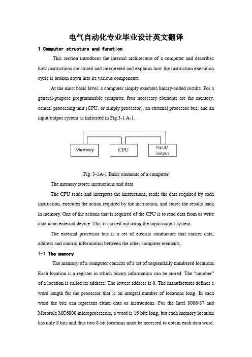
电气自动化专业毕业设计英文翻译1 Computer structure and functionThis section introduces the internal architecture of a computer and describes how instructions are stored and interpreted and explains how the instruction execution cycle is broken down into its various components.At the most basic level, a computer simply executes binary-coded results. For a general-purpose programmable computer, four necessary elements are the memory, central processing unit (CPU, or simply processor), an external processor bus, and an input/output system as indicated in Fig.3-1 A-1.Fig. 3-1A-1 Basic elements of a computerThe memory stores instructions and data.The CPU reads and interprets the instructions, reads the data required by each instruction, executes the action required by the instruction, and stores the results back in memory. One of the actions that is required of the CPU is to read data from or write data to an external device. This is carried out using the input/output system.The external processor bus is a set of electric conductors that carries data, address and control information between the other computer elements.1-1 The memoryThe memory of a computer consists of a set of sequentially numbered locations. Each location is a register in which binary information can be stored. The “number”of a location is called its address. The lowest address is 0. The manufacturer defines a word length for the processor that is an integral number of locations long. In each word the bits can represent either data or instructions. For the Intel 8086/87 and Motorola MC6800 microprocessors, a word is 16 bits long, but each memory location has only 8 bits and thus two 8-bit locations must be accessed to obtain each data word.In order to use the contents of memory, the processor must fetch the contents of the right location. To carry out a fetch, the processor places (enables) the binary-coded address of the desired location onto the address lines of the external processor bus. The memory then allows the contents of the addressed memory location to be read by the processor. The process of fetching the contents of a memory location does not alter the contents of that location.Instructions in memory Instructions stored in memory are fetched by the CPU and unless program branches occur, they are executed in the sequence they appear in memory. An instruction written as a binary pattern is called a machine-language instruction. One way to achieve meaningful patterns is to divide up the bits into fields as indicated in Fig. 3-1A-2, with each field containing a code for a different type of information.0001 0101 1000 XXXX 0100 0001 1000 XXXX 0011 XXXX XXXX 0100 Fields Opcode Immediate code Operand data Branch addressSet ‘5’ in location 8 Subtract ‘1’ f rom location 8 If zero, bran ch to location 416-bit instruction words... ... XXXX : not u sed (or “don ’t care”)Fig. 3-1A-2 Arrangement of program and data in memoryEach instruction in our simple computer can be divided up into four fields of 4 bits each. Each instruction can contain operation code (or opcode, each instruction has a unique opcode), operand address, immediate operands, branch address.In a real instruction set there are many more instructions. There is also a much large number of memory locations in which to store instructions and data. In order to increase the number of memory locations, the address fields and hence the instructions must be longer than 16 bits if we use the same approach. There are a number of ways to increase the addressing range of the microprocessor withoutincreasing the instruction length: variable instruction field, multiword instructions, multiple addressing modes, variable instruction length. We will not discuss them in detail.Data in memory data is information that is represented in memory as a code. For efficient use of the memory space and processing time, most computers provide the capability of manipulating data of different lengths and representations in memory. The various different representations recognized by the processor are called its data types. The data types normally used are: bit, binary-coded decimal digit (4-bit nibble, BCD), byte (8 bits), word (2 bytes), double word (4 bytes).Some processors provide instructions that manipulate other data types such as single-precision floating-point data types (32bits) and double-precision floating-point data types (64 bits). There is another type of data—character data. It is also usually represented in 8 bits. Each computer terminal key and key combination (such as shift and control functions) on a standard terminal keyboard has a 7-bits code defined by the American Standard Code for Information Interchange (ASCII).Type of memory In the applications of digital control system, we also concerned with the characteristics of different memory techniques. For primary memory, we need it to be stored information temporarily and to be written and got information from successive or from widely different locations. This type memory is called random-access memory (RAM). In some case we do not want the information in memory to be lost. So we are willing to use special techniques to write into memory. If writing is accomplished only once by physically changing connections, the memory is called a read-only memory (ROM). If the interconnection pattern can be programmed to be set, the memory is called a programmable read-only memory (PROM). If rewriting can be accomplished when it is necessary, we have an erasable programmable read-only memory (EPROM). An electronically erasable PROM is abbreviated EEPROM.1-2 The CPUThe CPU’s job is to fetch instructions from memory and execute these instructions. The structure of the CPU is shown in Fig. 3-1A-3. It has four maincomponents: an arithmetic and logical unit (ALU), a set of registers, an internal processor bus and controller.Fig.3-1A-3 Central processing unit (CPU)These and other components of the CPU and their participation in the instruction cycle are described in the following sections.Arithmetic and Logical Unit (ALU) The ALU provides a wide arithmetic operations, including add, subtract, multiply, and divide. It can also perform Boolean logic operations such as AND, OR, and COMPLEMENT on binary data. Other operations, such as word compares, are also available. The majority of computer tasks involve the ALU, but a great amount of data movement is required in order to make use of the ALU instructions.Registers A set of registers inside the CPU in used to store information.Instruction register When an instruction is fetched, it is copied into the instruction register, where it is decoded. Decoding means that the operation code is examined and used to determine the steps of the execution sequence.Programmer’s model of the CPU The collection of registers that can be examined or modified by a programmer is called the programmer’s model of the CPU. The only registers that can be manipulated by the instruction set, or are visibly affected by hardware inputs or the results of operations upon data, are the registers represented in the model.Flag register The execution sequence is determined not only by the instruction but also by the results of the previous instructions. For example, if an addition is carried out in the ALU, data on the result of the addition (whether the result is positive, negative, or zero, for example) is stored in what is known as a flag register, status register, or condition register. If the next instruction is a conditional branch instruction, the flag word is tested in that instruction to determine if a branch if a branch is required.Program counter (instruction pointer)The address of the next instruction is located in a register called the program counter.Data registers When an instruction uses the registers to store data, the reference to the register in the instruction is called register addressing. The reasons of making use of the internal registers to store data are that they can make the instructions shorter and make execution faster.Address registers The internal registers can also be used for the storage of address of data in memory data. In such a case, the instruction word contains a register number (i.e. a register address). In the register is contained the address of memory data to be used in the instruction. This form of addressing is called register indirect addressing. The contents of the register are said to point to the data in memory.Internal Processor Bus The internal processor bus moves data between internal register. A bus is a set of closely grouped electric conductors that transfers data, address, and control information between functional blocks of the CPU. Data from a source register can be passed to a destination register when both are enabled onto (connected to) the bus.Controller The controller provides the proper sequence of control signals for each instruction in a program cycle to be fetched from memory. A total program cycle comprises many instruction cycle, each instruction cycle can be divided up into its component machine cycles and each machine cycle comprises a number of clock cycle.In order to fetch an instruction, for example illustrated in Fig.3-1A-4, the addressin the program counter is placed on the address lines of the external bus (AB) at the onset of clock cycle C1. Simultaneously, using a code on the control lines of the bus (CB), the CPU informs all devices attached to the bus that an “opcode” fetch machine cycle is being executed by the CPU. The memory allows the memory address to select the memory location containing the instruction. At C2 the controller places a “read”command onto the control bus which allows the memory data to be placed onto the data bus. The controller then gates the data into the instruction register and removes the read command from the control bus in C3. At C4, the controller removes the address from the address bus and begins to decode the operation-code portion of the instruction to see what steps are required for execution. The decoding operation may take several more clock cycle at the end of which the “opcode fetch” machine cycle.Fig. 3-1A-4 A timing diagram for "operation-code fetch "External attention requests It is often necessary to stop the normal instruction processing sequence. One type of external attention request is the reset request. In the case of an unrecoverable error, a computer system may be required to reset itself .This would have the effect of initializing all important registers in the system and starting instruction execution from a standard memory location-usually location 0.An input that is more commonly activated during the normal course of events is the interrupt request. An interrupt request signal from an external device can cause theCPU to immediately execute a service subroutine which carries out the necessary actions. After completing the service subroutine, the processor will continue the task from which it was originally interrupted.The third type of input is the bus request, or direct memory access(DMA) request. It is possible to have a terminal interface that stores up all the characters in a line of text until it receives a "carriage return." Then the interface requests the use of the system bus, at which time the complete line of data is transferred to memory as fast as possible. In this way the processor simply becomes inactive until the transfer is completed.1-3 BusesThe bus is the most important communication system in a computer system. Under control of the CPU, a data source device and a data destination device are "enabled" onto(equivalent to being connected to) the bus wires for a short transmission.External processor bus The internal processor bus described in Sec. is connected to the external processor bus by a set of bus buffers located on the microprocessor integrated circuit.System bus The microcomputer board can communicate with other boards by connecting its bus to an external system bus through a connector.1-4Computer Input and OutputA set of registers external to the CPU is associated with what is known as the input/output (I/O) system. The I/O system is connected to the external processor bus using control, address, and data buses through an I/O registers in an interface. There are basically two ways that are used to address I/O register.In the first method, called I/O-mapped input/output, the operation code itself has special I/O instructions that address a numbered register in the interface called an I/O port.The second method of addressing I/O registers gives the I/O ports addresses that lie within the memory address range of the CPU. This is called memory-mapped I/O. Of course there must not be any memory locations at the same address as I/Olocations.One of the benefits of the memory-mapped approach is that the full range of memory addressing modes is available to the addressing of I/O registers.2Fundamentals of Computer and Networks2-1 Organization of Computer SystemA computer is a fast and accurate symbol manipulating system that is organized to accept, store, and process data and produce output results under the direction of a stored program of instructions. This section explains why a computer is a system and how a computer system is organized. Key elements in a computer system include input, processing, and output devices. Let's examine each component of the system in more detail.Input Devices Computer system use many devices for input purpose. Some INPUT DEVICES allow direct human/machine communication, while some first require data to be recorded on an input medium such as a magnetizable material. Devices that read data magnetically recorded on specially coated plastic tapes or flexible or floppy plastic disks are popular. The keyboard of a workstation connected directly to (or ONLINE to) a computer is an example of a direct input device. Additional direct input devices include the mouse, input pen, touch screen, and microphone. Regardless of the type of device used, all are components for interpretation and communication between people and computer systems.Central Processing Unit The heart of any computer system is the central processing unit (CPU). There are three main sections found in the CPU of a typical personal computer system: the primary storage section, the arithmetic-logic section, and the control section. But these three sections aren't unique to personal computers. They are found in CPUs of all sizes.Output Device Like input units, output device are instruments of interpretation and communication between humans and computer system of all size. These device take output results from the CPU in machine-coded form and convert them into a form that can be used (a) by people (e.g. a printed and /or displayed report) or (b) asmachine input in another processing cycle.In personal computer systems, display screen and desktop printers are popular output devices. Larger and faster printers, many on-line workstations, and magnetic tape drives commonly found in large systems.The input/output and secondary storage units are sometimes called peripheral devices (or just peripherals). This terminology refers to the fact that although these devices are not a part of the CPU, they are often located near it. Besides, a computer system also includes buses, ROM(read only memory), RAM(random access memory), parallel port and serial port, hard disk, floppies and CD(compact disk)drive, and so on.2-2 Operating SystemOperating systems have developed over the past thirty years for two main purposes. First, they provide a convenient environment for the development and execution of programs. Second, operating systems attempt to schedule computational activities to ensure good performance of the computing system.The operating system must ensure correct operation of the computer system. To prevent user programs form interfering with the proper operation of the system, the hardware was modified to create two modes: user mode and monitor mode. Various instructions (such as I/O instructions and halt instructions) are privileged and can only be executed in monitor mode. The memory in which the monitor resides must also be protected from modification by the user. A timer prevents infinite loops. Once these changes (dual mode, privileged instructions, memory protection, timer interrupt) have been made to the basic computer architecture, it is possible to write a correct operating system.As we have stated, operating systems are normally unique to their manufacturers and the hardware in which they are run. Generally, when a new computer system is installed, operational software suitable to that hardware is purchased. Users want reliable operational software that can effectively support their processing activities.Though operational software varies between manufacturers, it has similarcharacteristics. Modern hardware, because of its sophistication, requires that operating systems meet certain specific standards. For example, considering the present state of the field, an operating system must support some form of on-line processing. Functions normally associated with operational software are:1)Job management;2)Resource management;3)Control of I/O operations4)Error recovery;5)Memory management.2-3 NetworksCommunication between distributed communities of computers is required for many reasons. At a national level, for example, computers located in different parts of the country use public communication services to exchange electronic messages (mail) and to transfer files of information from one computer to another. Similarly, at a local level within, say, a single building, distributed communities of computer-based workstations use local communication networks to access expensive shared resources—for example, printers and disks tapes and copiers, etc.—that are also managed by computers. Clearly, as the range of computer-based products and associated public and local communication networks proliferate, computer-to-computer communication will expand rapidly and ultimately dominate the field of distributed systems.Although the physical separation of the communicating computers may vary considerably from one type of application to another, or, at the heart of any computer communication network is the data communication facility which, may be a PSDN, a private LAN or perhaps a number of such networks interconnected together. However, irrespective of the type of data communication facility, an amount of hardware and software is required within each attached computer to handle the appropriate network-dependent protocols. Typically, these are concerned with the establishment of a communication channel access the network and with the control of the flow of messages across this channel. The provision of such facilities is only part of thenetwork requirements, however, since in many applications the communicating computers may be of different forms of data representation interface between user (application) programs, normally referred to as application processes or APs, and the underlying communication services may be different. For example, one computer may be a small single-user computer, while another may be a large multi-user system.3 Stepper motorStepper motor is the electric pulse signals into angular displacement or linear displacement of the open-loop stepper motor control element pieces. In the case of non-overloaded, the motor speed, stop position depends only on the pulse frequency and pulse number, regardless of load changes, when the driver receives a step pulse signal, it will drive a stepper motor to Set the direction of rotation of a fixed angle, called the "step angle", which the angle of rotation is fixed step by step operation. Number of pulses can be controlled by controlling the angular displacement, so as to achieve accurate positioning purposes; the same time by controlling the pulse frequency to control the motor rotation speed and acceleration, to achieve speed control purposes.3-1 WorkInduction motor is a stepper motor, does it work is the use of electronic circuits, the DC power supply into a time-sharing, multi-phase timing control current, this current stepper motor power supply, the stepper motor to work properly , The drive is sharing power supply for the stepper motor, the polyphase timing controller.Although the stepper motor has been widely used, but the stepper motor does not like a normal DC motor, AC motor in the conventional use. It must be double-ring pulse signal; power driver circuit composed of the control system can be used. Therefore, it is not easy with a good stepping motor, which involves mechanical, electrical, electronics and computers, and much other specialized knowledge.As the stepper motor actuators, electromechanical integration, one of the key products, widely used in a variety of automatic control systems. With the developmentof microelectronics and computer technology, increasing demand for stepper motor has applications in all areas of the national economy.3-2 CategoriesNow more commonly used include the reaction of step motor stepper motor (VR), permanent magnet stepper motor (PM), hybrid stepper motors (HB) and single-phase stepper motor.3-3 Permanent magnet stepper motorPermanent magnet stepper motor is generally two-phase, torque, and smaller, usually 7.5 degree step angle or 15 degrees;Permanent magnet stepper motor output torque, dynamic performance, but a large step angle.3-4 Reaction Stepper MotorReaction is generally three-phase stepping motor can achieve high torque output, step angle of 1.5 degrees is generally, but the noise and vibration are large. Reaction by the stepper motor rotor magnetic circuit made of soft magnetic materials, a number of the stator phase excitation winding, the use of permeability changes in torque.Step Motor simple structure, low production costs, step angle is small; but the dynamic performance is poor.3-5 Hybrid Stepping MotorHybrid Step Motor combines reactive, permanent magnet stepper motors of both, it's a small step angle, contribute a large, dynamic performance, is currently the highest performance stepper motor. It is also sometimes referred to as Permanent Magnet Induction Stepping Motor. It consists of two phases and the five-phase: the general two-phase step angle of 1.8 degrees and the general five-phase step angle 0.72 degrees. The most widely used Stepper Motor. Stepper motor drive for energy saving 3-6 Three-phase stepper motor drive special features:◆180% low torque output, low frequency characteristics of a good run◆Maximum output frequency 600Hz, high-speed motor control◆full range of detection of protection (over voltage, under voltage, overload)instantaneous power failure restart◆acceleration, deceleration, such as dynamic change in the stall protection functionto prevent◆Electrical dynamic parameters of automatic recognition function to ensurestability and accuracy of the system◆quick response and high-speed shutdown◆abundant and flexible input and output interface and control, versatility◆use of SMT production and three full-mount anti-paint treatment process, productstability and high◆full range of Siemens IGBT power devices using the latest, to ensure the qualityof high-quality3-7 Basic principlesUsually for the permanent magnet rotor motor, when current flows through the stator windings, the stator windings produce a magnetic field vector. The magnetic field will lead to a rotor angle of the magnetic field makes the direction of a rotor and the stator's magnetic field direction. When the stator magnetic field vector rotating at an angle. As the rotor magnetic field is also transferred from another perspective. An electrical pulse for each input, the motor turning a point forward. It is the angular displacement of the output and input the number of pulses proportional to speed and pulse frequency is proportional to. Power to change the order of winding, the motor will reverse. Therefore, the number of available control pulse, frequency and power the motor windings of each phase in order to control the stepper motor rotation.3-8 Induction Stepping Motor3-8-1 features: Induction, compared with the traditional reactive, structural reinforced with a permanent magnet rotor, in order to provide the working point of soft magnetic materials, and the stator excitation magnetic field changes only need to provide to provide the operating point of the consumption of magnetic materials energy, so the motor efficiency, current, low heat. Due to the presence of permanent magnets, the motor has a strong EMF, the damping effect of its own good, it is relatively stable during operation, low noise, low frequency vibration. Induction canbe seen as somewhat low-speed synchronous motor. A four-phase motor can be used for four-phase operation, but also can be used for two-phase operation. (Must be bipolar voltage drive), while the motor is not so reactive. For example: four phase, eight-phase operation (A-AB-B-BC-C-CD-D-DA-A) can use two-phase eight-shot run. Not difficult to find the conditions for C =, D =. a two-phase motor's internal winding consistent with the four-phase motors, small power motors are generally directly connected to the second phase, the power of larger motor, in order to facilitate the use and flexible to change the dynamic characteristics of the motor, its external connections often lead to eight (four-phase), so that when used either as a four-phase motors used, can be used for two-phase motor winding in series or parallel.3-8-2 classification:Induction motors can be divided in phases: two-phase motor, three phase motor, four-phase motor, five-phase motor. The frame size (motor diameter) can be divided into: 42BYG (BYG the Induction Stepping motor code), 57BYG, 86BYG, 110BYG, (international standard), and like 70BYG, 90BYG, 130BYG and so are the national standards.3-8-3 the stepper motor phase number of static indicators of terms: very differently on the N, S the number of magnetic field excitation coil. Common m said. Beat number: complete the necessary cyclical changes in a magnetic field pulses or conducting state with n said, or that turned a pitch angle of the motor pulses needed to four-phase motor, for example, a four-phase four-shot operation mode that AB -BC-CD-DA-AB, shot eight four-phase operation mode that A-AB-B-BC-C-CD-D-DA-A. Step angle: corresponds to a pulse signal, the angular displacement of the rotor turned with θ said. θ = 360 degrees (the rotor teeth number of J * run shot), the conventional two, four-phase, the rotor teeth 50 tooth motor as an example. Four step run-time step angle θ = 360 ° / (50 * 4) = 1.8 degrees (commonly called the whole step), eight-shot running step angle θ = 360 ° / (50 * 8) = 0.9 degrees (commonly known as half step.) Location torque: the motor is not energized in the state, its locked rotor torque (as well as by the magnetic field profile of harmonics caused by mechanical error) static torque: the motor under the rated static electricity, the motor without rotation, the motor shaft locking torque. The motor torque is ameasure of volume (geometry) standards, and drive voltage and drive power, etc. has nothing to do. Although the static torque is proportional to the electromagnetic magnetizing ampere turns, and fixed air gap between the rotor teeth on, but over-use of reduced air gap, increase the excitation ampere-turns to increase the static torque is not desirable, this will cause the motor heating and mechanical noise.3-9 Characteristics of the stepper motor1. The general accuracy of the stepper motor step angle of 3-5%, and not cumulative.2. Appearance of the stepper motor to allow the maximum temperature.Stepper motor causes the motor temperature is too high the first magnetic demagnetization, resulting in loss of torque down even further, so the motor surface temperature should be the maximum allowed depending on the motor demagnetization of magnetic material points; Generally speaking, the magnetic demagnetization points are above 130 degrees Celsius, and some even as high as 200 degrees Celsius, so the stepper motor surface temperature of 80-90 degrees Celsius is normal.3. Stepper motor torque will decrease with the increase of speed.When the stepper motor rotates, the motor winding inductance of each phase will form a reverse electromotive force; the higher the frequency the greater the back emf. In its role, the motor with frequency (or speed) increases with the phase current decreases, resulting in decreased torque.4. Low-speed stepper motor can operate normally, but if not higher than a certain speed to start, accompanied by howling.Stepper motor has technical parameters: no-load starting frequency, ie the stepper motor with no load to start the normal pulse frequency, pulse frequency is higher than the value if the motor does not start, you may lose steps or stall occurs. In the case of a load, start frequency should be lower. If you want the motor to achieve high-speed rotation, the pulse frequency should speed up the process, which started lower frequency, and then rise by a certain acceleration of the desired frequency (motor speed from low rise to high-speed).Stepper motor with its significant features, in the era of digital manufacturing play。
电气毕业设计 英文翻译

The Role of the Power Supply within theSystem and Design ProgramThe power supply assumes a very unique role within a typical system. In many respects, it is the mother of the system. It gives the system life by providing consistent and repeatable power to its circuits. It defends the systemagainst the harsh world outside the confines of the enclosure and protects its wards by not letting them do harm to themselves. If the supply experiences a failure within itself, it must fail gracefully and not allow the failure to reach the system.Alas, mothers are taken for granted, and their important functions are not appreciated. The power system is routinely left until late in the design program for two main reasons. First, nobody wants to touch it because everybody wants to design more exciting circuits and rarely do engineers have a background in power systems. Secondly, bench supplies provide all the necessary power during the system debugging stage and it is not until the product is at the integration stage t hat one says “Oops, we forgot to design the power supply!” All too frequently, the designer assigned to the power supply has very little experience in power supply design and has very little time to learn before the product isscheduled to enter production.This type of situation can lead to the “millstone effect” which in simple terms means “You designed it, you fix it ( forever).” No wonder no one wants to touch it and, when asked, disavows any knowledge of having ever designeda power supply.1.1 Getting Started. This Journey Starts with the First QuestionIn order to produce a good design, many questions must be asked prior to the beginning of the design process. The earlier they are asked the better off you are. These questions also avoid many problems later in the design program due to lack of communication and forethought. The basic questions to be asked include the following.From the marketing department1. From what power source must the system draw its power? There are different design approaches for each power system and one can also get information as to what adverse operating conditions are experienced for each.2. What safety and radio frequency interference and electro magnetic interference(RFI/EMI) regulations must the system meet to be able to be sold into the target market? This would affect not only the electrical design butalso the physical design.3. What is the maintenance philosophy of the system? This dictates what sort of protection schemes and physical design would match theapplication.4. What are the environmental conditions in which the product must operate? These are temperature range, ambient RF levels, dust, dirt,shock, vibration, and any other physical considerations.5. What type of graceful degradation of product performance is desired when portions of the product fail? This would determine the type of power busing scheme and power sequencing that may be necessary within the system.From the designers of the other areas of the product1. What are the technologies of the integrated circuits that are being used within the design of the system? One cannot protect something, if one doesn’t know how it breaks.2. What are the “best guess” maximum and minimum limits of the load current and are there any intermittent characteristics in its current demand such as those presented by motors, video monitors, pulsed loads, and so forth? Always add 50 percent more to what is told to you since these estimates always turn out to be low. Also what are the maximum excursions in supply voltage that the designer feels that the circuit can withstand. This dictates the design approaches of the cross-regulation of theoutputs, and feedback compensation in order to provide the needs of the loads.3. Are there any circuits that are particularly noise-sensitive? These include analog-to-digital and digital-to-analog converters, video monitors, etc. This may dictate that the supply has additional filtering or may need to be synchronized to the sensitive circuit.4. Are there any special requirements of power sequencing that are necessary for each respective circuit to operate reliably?5. How much physical space and what shape is allocated for the power supply within the enclosure? It is always too small, so start negotiating for your fair share.6. Are there any special interfaces required of the power supply? This would be any power-down interrupts, etc., that may be required by any of theproduct’s circuits.This inquisitiveness also sets the stage for the beginning of the design by defining the environment in which the power supply must operate. This then forms the basis of the design specification of the power supply.1.2 Power System OrganizationThe organization of the power system within the final product should complement the product philosophy. The goal of the power system is to distribute power effectively to each section of the entire product and to do it in a fashion that meets the needs of each subsection within the product. To accomplish this, one or more power system organization can be used within the product.For products that are composed of one functional “module” that is inseparable during the product’s life, such as a cellular telephone, CRT monitor, RF receiver, etc., an integrated power system is the traditional system organization. Here, the product has one main power supply which is completely self-contained and outputs directly to the product’s circuits. An integrated power system may actually have more than one power supply within it if one of the load circuits has power demand or sequencing requirements which cannot be accommodated by the main power supply without compromising its operation.For those products that have many diverse modules that can be reconfigured over the life of the product, such as PCB card cage systems and cellular telephone ground stations, etc., then the distributed power system is more appropriate. This type of system typically has one main “bulk” power supply that provides power to a bus which is distributed throughout the entire product. The power needs of any one module within the system are provided by smaller, board-level regulators. Here, voltage drops experienced across connectors and wiring within the system do not bother the circuits.The integrated power system is inherently more efficient (less losses). The distributed system has two or more power supplies in series, where the overall power system efficiency is the product of the efficiencies of the two power supplies. So, for example, two 80 percent efficient power supplies in series produces an overall system efficiency of 64 percent.The typical power system can usually end up being a combination of the two systems and can use switching and linear power supplies.The engineer’s motto to life is “Life is a tradeoff” and it comes into play here. It is impossible to design a power supply system that meets all the requirements that are initially set out by the other engineers and management and keep it within cost, space, and weight limits. The typical initial requirement of a power supply is to provide infinitely adaptable functions, deliver kilowatts within zero space, and cost no money. Obviously, some compromise is in order.1.3 Selecting the Appropriate Power Supply TechnologyOnce the power supply system organization has been established, the designer then needs to select the technology of each of the power supplies within the system. At the early stage of the design program, this process may be iterative between reorganizing the system and the choice of power supply technologies. The important issues that influence this stage of the design are:1. Cost.2. Weight and space.3. How much heat can be generated within the product.4. The input power source(s).5. The noise tolerance of the load circuits.6. Battery life (if the product is to be portable).7. The number of output voltages required and their particular characteristics.8. The time to market the product.The three major power supply technologies that can be considered withina power supply system are:1. Linear regulators.2. Pulsewidth modulated (PWM) switching power supplies.3. High efficiency resonant technology switching power supplies.Each of these technologies excels in one or more of the system considerations mentioned above and must be weighed against the other considerations to determine the optimum mixture of technologies that meet the needs of the final product. The power supply industry has chosen to utilize each of the technologies within certain areas of product applications as detailed in the following.LinearLinear regulators are used predominantly in ground-based equipments where the generation of heat and low efficiency are not of major concern and also where low cost and a short design period are desired. They are very popular as boardlevel regulators in distributed power systems where the distributed voltage is less than 40VDC. For off-line (plug into the wall) products, a power supply stage ahead of the linear regulator must be provided for safety in order to produce dielectric isolation from the ac power line. Linear regulators can only produce output voltages lower than their input voltages and each linear regulator can produce only one output voltage. Each linear regulator has an average efficiencyof between 35 and 50 percent. The losses are dissipated as heat.PWM switching power suppliesPWM switching power supplies are much more efficient and flexible in their use than linear regulators. One commonly finds them used within portable products, aircraft and automotive products, small instruments, off-line applications, and generally those applications where high efficiency and multiple output voltages are required. Their weight is much less than that of linear regulators since they require less heatsinking for the same output ratings. They do, however, cost more to produce and require more engineering development time.High efficiency resonant technology switching power suppliesThis variation on the basic PWM switching power supply finds its place in applications where still lighter weight and smaller size are desired, and most importantly, where a reduced amount of radiated noise (interference) is desired. The common products where these power supplies are utilized are aircraft avionics, spacecraft electronics, and lightweight portable equipment and modules. The drawbacks are that this power supply technology requires the greatest amount of engineering design time and usually costs more than the other two technologies.The trends within the industry are away from linear regulators (except for board-level regulators) towards PWM switching power supplies. Resonant and quasi-resonant switching power supplies are emerging slowly as the technology matures and their designs are made easier.1.4 Developing the Power System Design SpecificationBefore actually designing the power system, the designer should developthe power system design specification. The design specification acts as the performance goal that the ultimate power supply must meet in order for the entire product to meet its overall performance specification. Once developed, it should be viewed as a semi-firm document and should only be changed after the needs of the product formally change. When developing the design specification, the power supply designer must keep in mind what is a reasonable requirement and what is an idealistic requirement. Engineers not experienced in power supply design often will produce requirements on the power supply that either will cost an unnecessary fortune and take up too much space or will be impossible to meet with the present state of the technology. Here the power supply designer should press the other engineers, managers, and marketers for compromises that will prompt them to review their requirements to decide what they can actually live with.The power system specification will be based upon the questions that should previously have been asked of the other departments involved in defining and designing the product. Some of the requirements can be anticipated to grow, such as the current needed by various subsystems within the product. Always add 25 to 50 percent to the output current capabilities of the power supply during the design process to accommodate this inevitable event. Also, the space allocated to the power system and its cost will almost always be less than what will be finally required. Some negotiations will be in order. Since the power system is a support function within the product, its design will always be modified in reaction to design issues within the other sections of the product. This will always make the power supply design the last circuit to be released for production. Recognizing and addressing these potential trouble areas early in the design period will help avoid delays later in the program.电源在系统中的作用和电源设计流程电源在一个典型系统中担当着非常重要的角色。
毕业设计毕业论文电气工程及其自动化外文翻译中英文对照
理工大学毕业设计(外文翻译材料)学院:专业:学生姓名:指导教师:电气与电子工程学院电气工程及其自动化- .专业文档.Relay protection development present situationAbstract: Reviewed our country electrical power system relay protection technological development process, has outlined the microcomputer relay protection technology achievement, propose the future relay protection technological development tendency will be: Computerizes, networked, protects, the control, the survey, the data communication integration and the artificial intellectualization.Key word: relay protection, present situation development, future development1 relay protection development present situationThe electrical power system rapid development to the relay protection propose unceasingly the new request, the electronic technology, computer technology and the communication rapid development unceasingly has poured into the new vigor for the relay protection technology development, therefore, the relay protection technology is advantageous, has completed the development 4 historical stage in more than 40 years time.After the founding of the nation, our country relay protection discipline, the relay protection design, the relay manufacture industry and the relay protection technical team grows out of nothing, has passed through the path in about 10 years which advanced countries half century passes through. The 50's, our country engineers and technicians creatively absorption, the digestion, have grasped the overseas advanced relay protection equipment performance and the movement technology , completed to have the deep relay protection theory attainments and the rich movement experience relay protection technical team, and grew the instruction function to the national relay protection technical team's establishment. The relay factory introduction has digested at that time the overseas advanced relay manufacture technology, has established our country relay manufacturing- .专业文档.industry. Thus our country has completed the relay protection research, the design, the manufacture, the movement and the teaching complete system in the 60's. This is a time which the mechanical and electrical relay protection prospers, was our countries relay protection technology development has laid the solid foundation.From the end of the 50's, the transistor relay protection was starting to study. In the 60's to the 80's,it is the times which the transistor relay protection vigorous development and widely used. Tianjin University and the Nanjing electric power automation plant cooperation research 500kV transistor direction high frequency protection the transistor high frequency block system which develops with the Nanjing electric power automation research institute is away from the protection, moves on the Gezhou Dam 500kV line , finished the 500kV line protection to depend upon completely from the overseas import time.From the 70's, start based on the integration operational amplifier integrated circuit protection to study. Has formed the completely series to at the end of 80's integrated circuit protection, substitutes for the transistor protection gradually. The development, the production, the application the integrated circuit protects which to the beginning of the 90's still were in the dominant position, this was the integrated circuit protection time. The integrated electricity road work frequency conversion quantity direction develops which in this aspect Nanjing electric power automation research institute high frequency protected the vital role, the Tianjin University and the Nanjing electric power automation plant cooperation development integrated circuit phase voltage compensated the type direction high frequency protection also moves in multi- strip 220kV and on the 500kV line.Our country namely started the computer relay protection research from the end of the 70's, the institutions of higher learning and the scientific research courtyard institute forerunner's function. Huazhong University of- .专业文档.Science and Technology, southeast the university, the North China electric power institute, the Xian Jiao tong University, the Tianjin University, Shanghai Jiao tong University, the Chongqing University and the Nanjing electric power automation research institute one after another has all developed the different principle, the different pattern microcomputer protective device. In 1984 the original North China electric power institute developed the transmission line microcomputer protective device first through the evaluation and in the system the find application, had opened in our country relay protection history the new page, protect the promotion for the microcomputer to pave the way. In the host equipment protection aspect, the generator which southeast the university and Huazhong University of Science and Technology develop loses magnetism protection, the generator protection and the generator? Bank of transformers protection also one after another in 1989、1994 through appraisal and investment movement. The Nanjing electric power automation research institute develops microcomputer line protective device also in 1991 through appraisal. The Tianjin University and the Nanjing electric power automation plant cooperation development microcomputer phase voltage compensated the type direction high frequency protection, the Xian Jiao tong University and the Xuchang Relay Factory cooperation development positive sequence breakdown component direction high frequency protection also one after another in 1993, in 1996 through the appraisal. Here, the different principle, the different type microcomputer line and the host equipment protect unique, provided one batch of new generation of performance for the electrical power system fine, the function has been complete, the work reliable relay protection installment. Along with the microcomputer protective device research, in microcomputer aspect and so on protection software, algorithm has also yielded the very many theories result. May say- .专业文档.started our country relay protection technology from the 90's to enter the time which the microcomputer protected.2 relay protections future developmentThe relay protection technology future the tendency will be to computerizes, networked, the intellectualization, will protect, the control, the survey and the data communication integration development.2.1 computerizesAlong with the computer hardware swift and violent development, the microcomputer protection hardware also unceasingly is developing. The original North China electric power institute develops the microcomputer line protection hardware has experienced 3 development phases: Is published from 8 lists CPU structure microcomputer protection, does not develop to 5 years time to the multi- CPU structure, latter developed to the main line does not leave the module the big modular structure, the performance enhances greatly, obtained the widespread application. Huazhong University of Science and Technology develops the microcomputer protection also is from 8 CPU, develops to take the labor controlling machine core partially as the foundation 32 microcomputers protection.The Nanjing electric power automation research institute from the very beginning has developed 16 CPU is the foundation microcomputer line protection, obtained the big area promotion, at present also is studying 32 protections hardware system. Southeast the university develops the microcomputer host equipment protects the hardware also passed through improved and the enhancement many times. The Tianjin University from the very beginning is the development take more than 16 CPU as the foundation microcomputer line protection, in 1988 namely started to study take 32 digital signals processor (DSP) as the foundation protection, the control, the survey integration microcomputer installment, at present cooperated with- .专业文档.the Zhuhai automatic equipment company develops one kind of function complete 32 big modules, a module was a minicomputer. Uses 32 microcomputers chips only to focus by no means on the precision, because of the precision the a/d switch resolution limit, is surpassed time 16 all is accepts with difficulty in the conversion rate and the cost aspect; 32 microcomputers chips have the very high integration rate more importantly, very high operating frequency and computation speed, very big addressing space, rich command system and many inputs outlet. The CPU register, the data bus, the address bus all are 32, has the memory management function, the memory protection function and the duty transformation function, and (cache) and the floating number part all integrates the high speed buffer in CPU.The electrical power system the request which protects to the microcomputer enhances unceasingly, besides protection basic function, but also should have the large capacity breakdown information and the data long-term storage space, the fast data processing function, the formidable traffic capacity, with other protections, the control device and dispatches the networking by to share the entire system data, the information and the network resources ability, the higher order language programming and so on. This requests the microcomputer protective device to have is equal to a pc machine function. In the computer protection development initial period, once conceived has made the relay protection installment with a minicomputer. At that time because the small machine volume big, the cost high, the reliability was bad, this tentative plan was not realistic. Now, with the microcomputer protective device size similar labor controlling machine function, the speed, the storage capacity greatly has surpassed the same year small machine, therefore, made the relay protection with complete set labor controlling machine the opportunity already to be mature, this will be one of development directions which the microcomputer protected. The- .专业文档.Tianjin University has developed the relay protection installment which Cheng Yong tong microcomputer protective device structure quite same not less than one kind of labor controlling machine performs to change artificially becomes. This kind of equipment merit includes: has the 486pc machine complete function, can satisfy each kind of function request which will protect to current and the future microcomputer. size and structure and present microcomputer protective device similar, the craft excellent, quakeproof, guards against has been hot, guards against electromagnetic interference ability, may move in the very severe working conditions, the cost may accept. Uses the STD main line or the pc main line, the hardware modulation, may select the different module willfully regarding the different protection, the disposition nimble, and is easy to expand.Relay protection installment, computerizes is the irreversible development tendency. How but to satisfies the electrical power system request well, how further enhances the relay protection the reliability, how obtains the bigger economic efficiency and the social efficiency, still must conduct specifically the thorough research.2.2 networkedThe computer network has become the information age as the information and the data communication tool the technical prop, caused the human production and the social life appearance has had the radical change. It profoundly is affecting each industry domain, also has provided the powerful means of communication for each industry domain. So far, besides the differential motion protection and the vertical association protection, all relay protections installment all only can respond the protection installment place electricity spirit. The relay protection function also only is restricted in the excision breakdown part, reduces the accident to affect the scope. This mainly is because lacks the powerful data communication method. Overseas already had proposed the system protection concept, this in mainly referred- .专业文档.to the safe automatic device at that time. Because the relay protection function not only is restricted in the excision breakdown part and the limit accident affects the scope (this is most important task), but also must guarantee the entire system the security stable movement. This requests each protection unit all to be able to share the entire system the movement and the breakdown information data, each protection unit and the superposition brake gear in analyze this information and in the data foundation the synchronized action, guarantees the system the security stable movement. Obviously, realizes this kind of system protection basic condition is joins the entire system each main equipment protective device with the computer network, that is realization microcomputer protective device networked. This under the current engineering factor is completely possible.Regarding the general non- system protection, the realization protective device computer networking also has the very big advantage. The relay protection equipment can obtain system failure information more, then to the breakdown nature, the breakdown position judgment and the breakdown distance examination is more accurate. Passed through the very long time to the auto-adapted protection principle research, also has yielded the certain result, but must realize truly protects to the system movement way and the malfunction auto-adapted, must obtain the more systems movement and the breakdown information, only then realization protection computer networked, can achieve this point.Regarding certain protective device realization computer networking also can enhance the protection the reliability. The Tianjin University in 1993 proposed in view of the future Three Gorges hydroelectric power station 500kv ultrahigh voltage multi-return routes generatrix one kind of distributional generatrix protection principle, developed successfully this kind of equipment initially. Its principle is disperses the traditional central- .专业文档.generatrix protection certain (with to protect generatrix to return way to be same) the generatrix protection unit, the dispersible attire is located in on various return routes protection screen, each protection unit joins with the computer network, each protection unit only inputs this return route the amperage, after transforms it the digital quantity, transmits through the computer network for other all return routes protection unit, each protection unit acts according to this return route the amperage and other all return routes amperage which obtains from the computer network, carries on the generatrix differential motion protection the computation, if the computed result proof is the generatrix interior breakdown then only jumps the book size return route circuit breaker, Breakdown generatrix isolation. When generatrix area breakdown, each protection unit all calculates for exterior breakdown does not act. This kind the distributional generatrix protection principle which realizes with the computer network has the high reliability compared to the traditional central generatrix protection principle. Because if a protection unit receives the disturbance or the miscalculation when moves by mistake, only can wrongly jump the book size return route, cannot create causes the generatrix entire the malignant accident which excises, this regarding looks like the Three Gorges power plant to have the ultrahigh voltage generatrix the system key position to be extremely important.By above may know, microcomputer protective device may enhance the protection performance and the reliability greatly, this is the microcomputer protection development inevitable trend.2.3 protections, control, survey, data communication integrationsIn realization relay protection computerizing with under the condition, the protective device is in fact a high performance, the multi-purpose computer, is in an entire electrical power system computer network intelligent terminal. It may gain the electrical power system movement and- .专业文档.breakdown any information and the data from the net, also may protect the part which obtains it any information and the data transfer for the network control center or no matter what a terminal. Therefore, each microcomputer protective device not only may complete the relay protection function, moreover in does not have in the breakdown normal operation situation also to be possible to complete the survey, the control, the data communication function that is realization protection, control, survey, data communication integration.At present, in order to survey, the protection and the control need, outdoor transformer substation all equipment, like the transformer, the line and so on the secondary voltage, the electric current all must use the control cable to direct to . Lays the massive control cable not only must massively invest, moreover makes the secondary circuit to be extremely complex. But if the above protection, the control, the survey, the data communication integration computer installation, will install in outdoor transformer substation by the protection device nearby, by the protection device voltage, the amperage is changed into after this installment internal circulation the digital quantity, will deliver through the computer network, then might avoid the massive control cable. If takes the network with the optical fiber the transmission medium, but also may avoid the electromagnetic interference. Now the optical current transformer (OTA) and the optical voltage transformer (OTV) in the research trial stage, future inevitably obtained the application in the electrical power system. In uses OTA and in the OTV situation, the protective device should place is apart from OTA and the OTV recent place, that is should place by the protection device nearby. OTA and the OTV light signal inputs after this integration installment in and transforms the electrical signal, on the one hand serves as the protection the computation judgment; On the other hand took the survey quantity, delivers through the network. May to deliver from through the network by the- .专业文档.protection device operation control command this integrated installment, carries out the circuit breaker operation from this the integrated installment. In 1992 the Tianjin University proposed the protection, the control, the survey, the correspondence integration question, and has developed take the tms320c25 digital signal processor (DSP) as a foundation protection, the control, the survey, the data communication integration installment.2.4 intellectualizationsIn recent years, the artificial intelligence technology like nerve network, the genetic algorithms, the evolution plan, the fuzzy logic and so on all obtained the application in electrical power system each domain, also started in the relay protection domain application research. The nerve network is one non-linear mapping method, very many lists the complex non-linear problem with difficulty which the equation or solves with difficulty, the application nerve network side principle may be easily solved. For example exhibits in the situation in the transmission line two sides systems electric potential angle to occur after the transition resistance short-circuits is a non-linear problem, very difficult correctly to make the breakdown position from the protection the distinction, thus creates moves by mistake or resists to move; If thinks after the network method, passes through the massive breakdowns sample training, so long as the sample centralism has fully considered each kind of situation, then in breaks down time any all may correctly distinguish. Other likes genetic algorithms, the evolution plan and so on also all has its unique solution complex question the ability. May cause the solution speed these artificial intelligence method suitable unions to be quicker? The Tianjin University carries on the nerve network type relay protection from 1996 the research, has yielded the preliminary result. May foresee, the artificial intelligence technology must be able to obtain the application in the relay protection domain, by solves the problem which solves with difficulty with the conventional method.- .专业文档.3 conclusionsSince the founding of China's electric power system protection technology has undergone four times. With the rapid development of power systems and computer technology, communications technology, relay technology faces the further development of the trend. Domestic and international trends in the development of protection technologies: computerization, networking, protection, control, measurement, data communications integration and artificial intelligence, which made protection workers difficult task, but also opened up the activities of vast.- .专业文档.继电保护发展现状摘要:回顾我国电力系统继电保护技术的发展过程,概述了微机继电保护技术成果,提出了未来继电保护技术的发展趋势将是:计算机化,网络化,保护,控制,调查,数据通信一体化和人工智能化。
电气自动化自动控制毕业设计外文翻译[管理资料]
![电气自动化自动控制毕业设计外文翻译[管理资料]](https://img.taocdn.com/s3/m/c7e8ca067c1cfad6195fa7f4.png)
华北电力大学毕业设计(论文)附件外文文献翻译学号:姓名:所在院系:专业班级:指导教师:原文标题: FUZZY COORDINATED CONTROL OF A POWER UNIT2008年6月19日单元机组模糊协调控制1摘要本篇论文提出一种系统方法来实现补偿多回路协调控制策略。
该方法使用模糊系统,使火电厂单元机组可以承担大范围负荷跟踪。
它可以被描述为是用两个步骤来改进常规协调控制方法的方法。
第一步,,这使得改进后的调节器拥有更大的调节范围。
第二步,用一个根据机组输入输出数据设计的MIMO (Multiple-Input Multiple-Output)模糊补偿器来处理由动态工艺系统中的非线性和耦合作用而造成的控制回路之间存在的相互作用。
仿真试验显示了提出的方法的可行性和表现。
关键词:火电机组,大范围操作,负荷跟踪,协调控制,模糊PID控制器,MIMO模糊补偿器。
1绪论电厂火电机组用一系列能量转换过程来实现火力发电。
粗略的说,最主要的能量转换在于燃烧燃料,产生蒸汽,并推动汽轮机转动产生电力,然后蒸汽被冷凝。
所有这些转换构成一个大的热力循环,并且这些转换相互关系紧密。
机组整体控制策略的目标在于使机组发出合适的电力来满足负荷的需求,同时维持机组内部能量转换过程的平衡。
这些策略分为三类:锅炉跟随,汽轮机跟随和协调控制(CC)。
协调控制策略是综合前两种控制策略优点的控制策略。
它最主要的任务是协调锅炉侧响应的大延迟和和汽轮机侧的快速响应,从而使机组能够快速对负荷变化和扰动做出响应。
也就是说,锅炉提供的热能必须时刻和汽轮机所带的负荷相匹配。
简单来说,目前的协调控制方案包括分散多回路组态的ID算法估值的单输入输出控制器。
这些方案在需要大范围负荷跟踪调节的系统上的应用受到了极大的挑战。
在这些状态下,由于大范围的非线性变化和系统间的耦合作用,系统输出甚至会减小到临界点。
目前有几种建议使用先进控制技术来提增强回路协调控制系统。
电气专业毕业设计外文翻译

附录AA few examples will refresh your memory about the content of Chapter 8 and thegeneral approach to a nodal-analysis solution.EXAMPLE 17.12 Determine the voltage across the inductor for the network of Fig.Solution:Steps 1 and 2 are as ndicated in Fig.17.22.Step 3:Note Fig.17.23 for the application of Kirchhoff ’s current law to node V1:Fig.17.22 Fig.17.23∑Ii=∑I0 0=I1+I2+I3V1-E/Z1+(V1/Z2)+(V1-V2)/Z3=0Rearranging terms: V1[1/Z1+1/Z2+1/Z3]-V2[1/Z3]=E1/Z1 (17.1)Note Fig.17.24 for the application of Kirchhoff ’s current law to node V2:0=I3+I4+IV2-V1/Z3+V2/Z4+I=0Rearranging terms: V2[1/Z3+1/Z4]-V1[1/Z3]=-I (17.2)Fig.17.24Grouping equations: V1[1/Z1+1/Z2+1/Z3]-V2[1/Z3]=E1/Z1V1[1/Z3]-V2[1/Z3+1/Z4] =I1/Z1+1/Z2+1/Z3=1/0.5k Ω+1/10 k Ω+1/2k Ω=2.5mS ∠-2.29°1/Z3+1/Z4=1/2k Ω+1/-5k Ω=0.539mS ∠21.80°and V1[2.5ms ∠-2.29°]-V2[0.5mS ∠0°]=24m Α∠0°V1[0.5mS ∠0°]-V2[0.539mS ∠21.80°]=4m Α∠0°with 24m Α∠0° -0.5mS ∠0°4mΑ∠0°-0.539mS∠21.80°V1= 2.5ms∠-2.29°-0.5mS∠0°0.5mS∠0°-0.539mS∠21.80°=(24mΑ∠0°)(-0.539mS∠21.80°)+(0.5mS∠0°)(4mΑ∠0°)/[(2.5ms∠-2.29°)(-0.539mS∠21.80°)+(0.5mS∠0°)(0.5mS∠0°)]=-10.01ν-j4.81ν/-1.021-j0.45=11.106ν∠-154.33°/1.116∠-156.21°V1=9.95∠1.88°MathCad The length and complexity of the above mathematical development strongly suggest the use of an alternative approach such as MathCad.Note in MathCad 17.2 that the equations are entered in the same format as Eqs.(17.1) and (17.2).Both V1 and V2 were generated,but because only V1 was asked for,it was the only solution converted to the polar form.In the lower solution the complexity was significantly reduced by simply recognizing that the current is in milliamperes and the impedances in kilohms. The result will then be in volts.K :=10³m :=0.01 rad :=1V1 :=1+j V2 :=1+j deg :=π/180GivenV1·[1/5·k+1/10j·k+1/2·k]-V2·1/2·k≈24·mV1·[1/2·k]-V2[1/2·k+1/-5j·k]≈4·mFind(V1,V2)= 9.944 +0.319j Volts1.786 -0.396j VoltsV1 :=9.944+0.319j V1 =9.949 arg(V1)=1.837·degRecognizing that current in mA results ehen Z is in kilohmns,an alternative format follows:GivenV1·[1/5+1/10j+1/2]-V2·1/2≈24V1·1/2-V2[1/2+1/-5j]≈4Find(V1,V2)= 9.944 +0.319j Volts1.786 -0.396j VoltsV1 :=9.944+0.319j V1 =9.949 arg(V1)=1.837·degMATHCAD 17.2Dependent Current Sources For dependent current sources,the procedure is modified as follows:Steps 1 and 2 are the same as those applied for independent sources.Step 3 is modified as follows:Treat each dependent current source like an independent source when Kirchhoff’s current law applied to each defined node.However,once the equations are established,substitute the equation for the controlling quantity to ensure that the unknowns are limited solely to the chosen nodal voltages.1.Step 4 is as before.EXAMPLE 17.13 Write the nodal equations for the network of Fig.17.25 having a dependent current source.Solution: Steps 1 and 2 are as defined in Fig.17.25.Fig.17.25.Step 3: At node V1, I=I1+I2V1/Z1+V1-V2/Z2-I=0and V1[1/Z1+1/Z2]-V2[1/Z2]=IAt node V2, I2+I3+ΚI=0V2-V1/Z2+V2/Z3+Κ[V1-V2/Z2]=0and V1[1-Κ/Z2]-V2[1-Κ/Z2+1/Z3]=0resulting in two equations and two unknowns.Independent Voltage Sources between Assigned Nodes For independent voltage sources between assigned nodes,the procedure is modified as follows:1.Steps 1 and 2 are the same as those applied for independent sources.2.Step 3 is modefied as follows:Treat each source betwwen defined nodes as ashort circuit(recall the supernode classification of Chapter 8),and write the nodal equations for each remaining independent node.Then relate the chosen nodal voltages to the independent voltage source to ensure that the unknowns of the ginal equations are limited solely to the nodal voltages.3.Step 4 is as before.EXAMPLE 17.14 Write the nodal equations for the network of Fig.17.26 having an independent source between two assigned nodes.Solution: Steps 1 and 2 defined in Fig.17.26.Step 3:Replacing the independent source E with a short-circuit equivalent results in a supernode that will generate the following equation when Kirchhoff’s current law is applied to node V1: I1=V1/Z1+V2/Z2+I2with V2-V1=EFig.17.26.and we have two equationsand two unknowns.Dependent Voltage Source between Defined Nodes For dependent voltage sources between defined nodes,the procedure is modified as follows:1.Steps 1 and 2 are the same as those applied for independent voltage sources.2.Step 3 is modified as follows:The procedure is essentially the same as thatapplied for independent voltage sources,except now the dependent sourcess having to be defined in terms of the chosen nodal voltage to ensure that the final equations have only nodal voltage as their unknown quantities.3.Step 4 is as before.EXAMPLE 17.15Write the nodal equations for the network of Fig.17.27 having a dependent voltage source between two defined nodes.Solution: Steps 1 and 2 are defined in Fig.17.27.Fig.17.27.Step 3:Replacing the dependent source μVx with a short-circuit equivalent will result in the following equation when Kirchhoff's current law is applied at node V1:I=I1+I2V1/Z1+(V1-V2)/Z2-I=0and V2=μVx=μ[V1-V2]or V2=μV1/1+μresulting in two equations and two unknowns.Note that because the impedance Z3 is in parallelwith a voltage source,it does not appear in the analysis.It will,however,affect the current through the dependent voltage source.Format ApproachA close examination of Eqs.(17.1) and (17.2) in Example 17.12 will reveal thatthey are the same equations that would have been obtained using the format approach introduce in Chapter 8.Recall that the approach required that the voltage source first be converted to a current source,but the writing of the equations was quite direct and minimized any chances of an error due to lost sign or missing term.The sequence of steps required to apply the format approach is the following:1.Choose a reference node and assign a subscripted voltage lable to the(N-1)remaining independent nodes of the network.2.The number of equations required for a complete solution is equal to the numberof subcripted voltages(N-1).Column 1 of each equation is formed by summing the admittances tied to the node of interest and multiplying the result by that subscripted nodal voltage.3.The mutual terms are always subtracted from the terms of the first column.It ispossible to have more than one mutual term if the nodal voltage of interest has an element in common with more than one other nodal voltage.Each mutual term is product of the mutual admittance and the other nodal voltage tied to that admittance.4.The column to the right of the equality sign is the algebraic sum of the currentsources tied to the node of interest.A current source is assigned a positive sign if it supplies current to a node,and a negative sign if it draws current from the node. Solve resulting simultaneous equations for the desired nodal voltages.The comments offered for mesh analysis regarding independent and dependent sources apply here also.EXAMPLE 17.16Using the format approach to nodal analysis,find the voltage across the 4-Ωresistor in Fig.17.28.Fig.17.28.Solution: Choosing nodes(Fig.17.29) and writing the nodal equations,we have Z1=R=4ΩZ2=jXl=j5ΩZ3=-jXc=-j2ΩFig.17.29V1(Y1+Y2)-V2(Y2)=-I1V2(Y3+Y2)-V1(Y2)=+I2or V1(Y1+Y2)-V2(Y2)=-I1-V1(Y2)+V2(Y3+Y2)=+I2Y1=1/Z1 Y2=1/Z2 Y3=1/Z3Using determinants yields-I1 -Y2+I2 Y2+Y3V1 = =-(Y3+Y2)I1+I2Y2/(Y1+Y2)(Y3+Y2)-Y2Y2Y1+Y2 -Y2-Y2 Y3+Y2=-(Y3+Y2)I1+I2Y2/Y1Y3+Y2Y3+Y1Y2Substituting numerical values,we haveV1=-[(1/-j2Ω)+(1/j5Ω)]6Α∠0°+4Α∠0°(1/j5Ω)/(1/4Ω)(1/-j2Ω)+(1/j5Ω)(1/-j2Ω)+(1/4Ω)(1/j5Ω)=-(+j0.5-j0.2)6∠0°+4∠0°(-j0.2)/(1/j8)+(1/10)+(1/j20)=(-0.3∠90°)(6∠0°)+4∠0°(-j0.2)/j0.125+0.1-j0.05=-1.8∠90°+0.8∠-90°/0.1+j0.075=2.6ν∠-90°/0.125∠36.87°V1=20.80ν∠-126.87°MathCad Using MathCad and the matrix format with the admittance parameters will quickly provide a solution for V1 in Example 17.16,as shown in MathCad 17.3.Z1 :=4 Z2 :=5j Z3 :=-2j rad :=1 deg :=π/180Y := [1/Z1+1/Z2] -1/Z2 I := -6 -1/Z2 [1/Z2+1/Z3] 4I/Y= -12.48 -16.64j Volts8.32 -2.24j VoltsV1 := -12.48 -16.64j V1=20.8 arg(V1)=-126.87·degV2 := 8.32 -2.24j V2=8.616 arg(V2)=-15.068·degMATHCAD 17.3EXAMPLE 17.17 Using the format approach,write the nodal equations for the network of Fig.17.30.Fig.17.30.Solution: The circuit is redrawn in Fig.17.31,whereZ1=R1+jXl1=7Ω+j8ΩE1=20ν∠0°Z3=-jXc=-j10ΩZ2=R2+jXl2=4Ω+j5ΩI1=10Α∠20°Z4=R3=8ΩConverting the voltage source to a current source and choosing nodes,we obtain Fig.17.32.Note the “neat”appearance of the network using the subscripted impedances.Working directly with Fig.17.30would be more difficult and could produce errors.Write the nodal equations: V1(Y1+Y2+Y3)-V2(Y3)=+I2V2(Y3+Y4)-V1(Y3)=+I1Y1=1/Z1 Y2=1/Z2 Y3=1/Z3 Y4=1/Z4 which are rewritten as V1(Y1+Y2+Y3)-V2(Y3)=+I2-V1(Y3)+V2(Y3+Y4)=+I1EXAMPLE 17.18 Write the nodal equations for the network of Fig.17.33.Do not solve.Solution: Choose nodes(Fig.17.34): Z1=R1 Z2=jXl1 Z3=R2-jXc2Z4=-jXc1 Z5=R3 Z6=jXl2 and write the nodal equations: V1(Y1+Y2)-V2(Y2)=+I1V2(Y2+Y3+Y4)-V1(Y2)-V3(Y4)=-I2V3(Y4+Y5+Y6)-V2(Y4)=+I2which are rewritten as V1(Y1+Y2)-V2(Y2)+0=+I1-V1(Y2)+ V2(Y2+Y3+Y4)-V3(Y4)=-I20-V2(Y4)+V3(Y4+Y5+Y6)=+I2Y1=1/R1 Y2=1/jXl1 Y3=1/R2-jXc2 Y4=-1/jXc1 Y5=1/R3 Y6=1/jXl2Fig.17.31Note the symmetry about the diagonal for this example and those preceding it in this section.EXAMPLE 17.19Apply nodal analysis to the network of Fig.17.35.Determine the voltage Vl.Solution: In this case there is no need for a source conversion.The network is redrawn in Fig.17.36 with the chosen nodal voltage and subscripted impedances.Apply the format approach: Y1=1/Z1=1/4kΩ=0.25mS∠0°= G1∠0°Y2=1/Z2=1/1kΩ=1mS∠0°= G1∠0°Y3=1/Z3=1/2kΩ∠90°=0.5mS∠-90°=-j0.5mS=-jBlV1: (Y1+Y2+Y3)V1=-100Iand V1=-100I/Y1+Y2+Y3=-100I/0.25mS+1mS-j0.5mS=-100×10³I/1.25-j0.5=-100×10³I/1.3463∠-21.80°=-74.28×10³I∠21.80°=-74.28×10³I(Vi/1kΩ)∠21.80°V1=Vl=-(74.28Vi)V∠21.80°17.6 BRIDGE NETWORKS(ac)The basic bridge figuration was discussed in some detali in Section 8.11 for dc networks.We now continue to examine bridge networks by considering those that have reactive components and a sinusoidal ac voltage or current applied.We will first analyze various familiar forms of the bridge network using mesh analysis and nodal analysis(the format approach).The balance conditions will be investigated throughout the section.Apply mesh analysis to the network of Fig.17.37.The network is redrawn in Fig.17.38,where Z1=1/Y1=1/G1+jBc=G1/(G1²+Bc ²)-jBc/( G1²+Bc²)Z2=R2 Z3=R3 Z4=R4+jXl Z5=R5Applying the format approach: (Z1+Z3)I1-(Z1)I2-(Z3)I3=EFig.17.32(Z1+Z2+Z5)I2-(Z1)I1-(Z5)I3=0(Z3+Z4+Z5)I3-(Z3)I1-(Z5)I2=0which are rewritten as (Z1+Z3)I1-(Z1)I2-(Z3)I3=E-(Z1)I1+(Z1+Z2+Z5)I2-(Z5)I3=0-(Z3)I1-(Z5)I2+(Z3+Z4+Z5)I3=0Note the symmetry about the diagonal of the above equations.For balabce,Iz5=0Α,andIz5=I2-I3=0From the above equations,Z1+Z3 E -Z3-Z1 0 -Z5-Z3 0 (Z3+Z4+Z5)I2==E(Z1Z3+Z1Z4+Z1Z5+Z3Z5)/ΔZ1+Z3 -Z1 -Z3-Z1 (Z1+Z2+Z5) -Z5-Z3 -Z5 (Z3+Z4+Z5)where Δsignifies the determinant of the denominator(or coefficients).Similarly,I3=E(Z1Z3+Z3Z2+Z1Z5+Z3Z5)/Δand Iz5=I2-I3=E(Z1Z4-Z3Z2)/ΔFor Iz5=0,the following must be satisfied(for a finite Δnot equal to zero):Z1Z1= Iz5=0 (17.3)This condition will be analyzed in greater depth later in this section.举几个例子就刷新你对第8章的内容和一般方法一节点,分析解决内存。
电气工程及其自动化专业毕业论文外文翻译
电气工程及其自动化专业毕业论文外文翻译本科毕业设计(论文)中英文对照翻译院(系部)工程学院专业名称电气工程及其自动化年级班级 11级2班学生姓名蔡李良指导老师赵波Infrared Remote Control SystemAbstractRed outside data correspondence the technique be currently within the scope of world drive extensive usage of a kind of wireless conjunction technique, drive numerous hardware and software platform support. Red outside the transceiver product have cost low, small scaled turn, the baud rate be quick, point to point SSL, be free from electromagnetism thousand Raos etc. characteristics, can realization information at dissimilarity of the product fast, convenience, safely exchange and transmission, at short distance wireless deliver aspect to own very obvious of advantage. Along with red outside the data deliver a technique more and more mature, the cost descend, red outside the transceiver necessarily will get at the short distance communication realm more extensive of application.The purpo se that design this system is transmit customer’s operation information with infrared rays for transmit media, then demodulate original signal with receive circuit. It use coding chip to modulate signal and use decoding chip to demodulate signal. The coding chip is PT2262 and decoding chip is PT2272. Both chips are made in Taiwan. Main work principle is that we provide to input the information for the PT2262 with coding keyboard. The input information was coded by PT2262 and loading to high frequent loadwave whose frequent is 38 kHz, then modulate infrared transmit dioxide and radiate space outside when it attian enough power. The receive circuit receive the signal and demodulate original information. The original signal was decoded by PT2272, so as to driv e some circuit to accomplish customer’s operation demand.Keywords: Infrared dray;Code;Decoding;LM386;Red outside transceiver1 Introduction1.1 research the background and significanceInfrared Data Communication Technology is the world wide use of a wireless connection technology, by the many hardware and software platforms supported. Is a data through electrical pulses and infrared optical pulse switch between the wireless data transceiver technology.Infrared transceiver products with low cost, small, fast transmission rate, the point-to-point transmission security, not subject to electromagnetic interference and other characteristics that can be achieved between the different products, rapid, convenient and safe exchange and transmission, In short distance wireless transmission have a very distinct advantage.Infrared transceiver products in the portable product of a great role. At present, the world's 150 million piece of equipment used infrared technology in electronic products and industrial equipment. medical equipment and other fields widely used. For example, 95% of the notebook computers on the installation of infrared transceiver interface the majority of the cell phone is also the allocation of infrared transceiver interface. With the exchange of quantitative data, infrared datacommunications will enable cell phone data transmission more convenient. With infrared data transmission technology matures, perfect, low costs, Infrared Transceiver in short distance communications will be more widely applied.This chapter first describes the infrared transceiver IC design issues to the background and significance. then briefed the infrared data communications technology features and applications, and infrared transceiver product characteristics, domestic and international situation and development trend of the last under infrared remote transceiver system in practical application to establish a task of design orientation. 1.2 Infrared Remote Control Transceiver SystemInfrared remote control system is divided into single-channel and multi-channel remote control. Only a command signal transmission channel, called single-channel remote control system; with more than two instructions signal transmission channel known as a multi-channel remote control system. Relatively simple single-channel remote control, in general, only a launcher directive Key receivers and only one circuit implementation. While in the receiving circuit to add more stable memory circuits that can be activated commands to launch a number of key, so that the receiver circuit multi stable memory circuit repeatedly to change the state, to realize many of the functional control, But such a state of change is the order. If we are to achieve an arbitrary control, resort to the use of multi-channel remote control system. Multi-channel remote control can be realized by the object of arbitrary multi-function remote control. As for the choice of several routes and what control methods, according to the actual situation (such as object, operational requirements and cost accounting, etc.) to decide. General infrared remote transceiver system by infrared remote control transmitter signal coding, infrared remotecontrol signal receivers and decoders (or decoder chip MCU) and the external circuit consisting of three parts. Signal transmitter remote control code used to generate pulses of infrared emission-driven output infrared remote control signal, receiver completion of the remote control signal amplification and detection, plastic and demodulation encoding pulse. Infrared remote control coded pulse is going to obtain a continuous serial binary code, and for most of the infrared transceiver system, This serial code as micro-controller of the remote control input signals from the internal CPU completion of the remote control instruction decoder, on the other infrared remote control transceivers, the designers of electronic products, The internal micro-controller of the remote control decoder directive is not accessible. Therefore, people are using infrared encoder / decoder chip and microcontroller developed various generic infrared remote transceiver system, In various equipment infrared signals between the transceiver.Remote transceiver system generally transmitters and receivers is composed of two parts. Launchers from the general direction keys, coded instructions circuit modulation circuit, driving circuit, firing circuit of several parts. When pressed a key, the directive coding circuit, in the corresponding instructions encoded signal, the encoder signal to the carrier modulation, Driven by the power amplifier circuit after circuit fired from the field after firing instructions coded modulation signals. General receiver by the receiving circuit, the amplifier circuit, demodulation circuits, instruction decoder circuit, driving circuit, circuit implementation of several parts. Receiving Circuit will launch vehicles have been coded modulation signal receiving instructions from, and to enlarge evacuation demodulation circuit. Demodulation circuit will havethe coding modulation signal demodulation, namely, reduction of signal coding. The instruction decoder to the encoder signal decoding, Driven by the final circuit to drive the implementation of various instructions circuit to control the operation.1.3 infrared remote control transceiver product profilesCurrently infrared transceiver in accordance with the mode of transmission rate and can be divided into four categories : Serial mode, the highest rate of 115.2 Kbps; medium-speed model : the highest rate of 0.567 Mbps and 1.152Mbps; High-speed mode : The maximum rate of 16 Mbps.Also according to the size chip power consumption can be divided into low-power consumption and standard two categories, low-power type normally used 3 V power supply, transmission distance closer to about 0 - 30cm, which is commonly used standard 5V power supply, transmission distance away at least 1m above.Infrared communication technology in the development stage and there are several infrared communication standards, between different standards for infrared equipment can not infrared communication. To have all the infrared equipment to interoperability in 1993 by more than 20 large manufacturers initiated the establishment of an Infrared Data Association (IRDA) unified the infrared communication standards , which is currently widely used in infrared data communication protocols and standards, also known as the IRDA standard.Since 1993 IRDA since the establishment of the Infrared Data Association members have developed to more than 150. IRDA standards of the industry has been widely recognized and supported. Has beendeveloped with the infrared communications equipment have been as many as 100 species. IR module, installed capacity has reached 150 million sets. Although there is also a short distance wireless Bluetooth technology, But in infrared communication technology low cost and broad compatibility advantages, Infrared data communication in the future will still be a very long time inherent short-range wireless data communications fields play an important role.In various infrared transceiver products, although the transmission rate, transmission distance and other characteristics, But infrared transceiver products has been towards improving the transmission rate, increase the transmission distance and lower power consumption, expanding launch reception angle of development. In particular, as the technology development and maturity, the means of transmission is moving in the direction of point-to-multipoint. Therefore infrared remote control transceiver products have broader prospects for development.2 Infrared communication of knowledge2.1 infrared ray foundation knowledgeInfrared is actually a kind of electromagnetic wave. From the analysis of various natural component of the electromagnetic wave reflected spectrum is :-ray, x-ray, ultraviolet, visible, infrared, microwave and radio wave. From the viewpoint of form, and they did not seem to, but if the wavelength in descending order, and we will find him all theonl y visible light spectrum of the entire 0.38 μm - 0.76μm so long little area, and adjacent to the visible light and infrared (including the far infrared, mid-infrared and near infrared foreign) accounts for the spectrum of 0.76 μm - 1000μm of a major. Which micron wavelength range also includes UV, visible, near infrared, mid-infrared and far-infrared, microwave.From the above analysis shows that infrared is a very rich spectrum resources, it currently has in production, life, military, medical, and other aspects have been widely used, such as infrared heating, medical infrared, infrared communication, infrared camera, infrared remote control, and so on. Infrared remote control is the many applications of infrared part of the current household appliances widely used in TV remote control, VCR remote control, VCD remote control, high-fidelity audio remote control, are used infra-red remote control, It allows the control of these appliances have become very easy.Infrared lies between visible light and microwave a wave, it is with certain clinical characteristics of the wave. In the near-infrared, visible light and its adjacent, it is visible in certain characteristics, such as straight-line transmission, reflection, refraction, scattering, diffraction, can be certain objects and can be absorbed through the lens of their focusing. In the far-infrared region, owing to its neighboring microwave, it has some characteristics of microwave, If a strong penetrating power and can run through some opaque substances. Since in any object, natural profession, regardless of whether its own luminescence (referring to visible light), as long as the temperature is above absolute zero (-273 ° C), moment will be kept around to infrared radiation. Only higher temperature of objects strong infrared radiation, low-temperature objectsinfrared radiation weaker. Therefore infrared feature is the greatest common in nature, it is called thermal radiation called thermal radiation. Infrared cameras, infrared night market pyroelectric infrared detectors and some other missiles aiming at is the use of this characteristic of infrared work.Infrared and visible light compared to another characteristic of a variety of colors. As the longest wavelength of visible light is a wavelength of the shortest times (780 nm-380 nm), So is called an octave. And infrared wavelength is the longest shortest wavelength of a times, and the longest wavelength infrared is the shortest wavelength of 10 times, that is, 10 octave. Therefore, if visible light can be expressed as seven colors, infrared may performance 70 colors, showing the rich colors. Infrared smoke through the good performance, which is also one of its features.Because not visible to the infrared, it has little effect on the environment. By the wave infrared rays than the long wavelength radio waves, infrared remote control will not affect the nearby radio equipment. Another wavelength of less than 1.5μm near infrared light, transparent atmosphere in the visible light transmission characteristics much better than, because it close to the visible edge of the red light, linear transmission, reflection, refraction and absorption material and the physical characteristics very similar to visible light. Therefore, it can be used with similar visible focusing lens and other optical devices. Because infrared remote control is not as remote as the radio through the barrier to control the object's ability to control, so in the design of household appliances infra-red remote control, wireless remote control as unnecessary, each set (transmitters and receivers) have different frequency or remote coding (Otherwise, wall will control or interference with neighbors household appliances), all similar products in the infraredremote control, The same can control the frequency or coding, and no remote control signal "drop." This universal infrared remote control provides a great convenience. Infrared to visible light, is very subtle and confidentiality, therefore, the security, Alert and other security devices have been widely used. Infrared remote control is simple in structure and easy, low-cost, anti-interference capability, high reliability are a number of advantages, is a close-up remote control, especially in indoor remote control optimized manner.Infrared is not visible, people here are not aware of. Electronic technology is used infrared light emitting diode (also known as the IR emission diode) to generate infrared. Infrared remote control transceiver is using near-infrared transmission control instructions 0.76μm wavelength of ~ 1. 5μm. Near-infrared remote control as a light source, because there infrared light emitting diodes and infrared receiving device (photo diode. Transistor and PV) and the luminescence peak wavelength of light by the general 0.8μm ~ 0. 94μm. in the near-infrared band, both of the spectrum is the coincidence to a good match, access to higher transmission efficiency and higher reliability. Commonly used infrared diode, and its shape is similar LED light emitting diodes, Its basic circuit shown in figure 2 -2. The triode plans for the switch, when the base added a driving signal, Transistor saturated conduction infrared LED D is also Wizard Link, issued infrared (near infrared about 0.93 μm). D. The pressure drop of about 1.4 V and the current general for 10-20mA. To adapt to the working voltage of the D loop resistance often as a series of infrared diode current limit resistance.When the circuit diagram of the infrared emission control corresponding to the controlled device, the control of the distance and D is proportional to the transmitting power. In order to increase the distance of infrared control, infrared diode D should work on the pulse state that work is the lifeblood of current. Because pulse light (optical modulation) the effective transmission distance and pulse is proportional to the peak current, only maximize peak current Ip, will increase the infrared distance. Ip increase is a way to reduce the pulse duty cycle, that is compressed pulse width τ some TV infrared remote control, i ts infrared luminescence of the pulse duty cycle of about 1/4-1/3; Some electrical products infrared remote control, its duty cycle of 1 / 10. Decreasing pulse duty cycle also enable low-power infrared LED distance of the greatly increased. Common infrared light emitting diodes, power is divided into small power (1 mW - 10mW). Chinese power (20mW - 50mW) and power (50mW - 100mW more) three categories. Use different power infrared LED, the allocation should be driven by the corresponding power control. Figure 2 -2 by the reflected infrared light-emitting diodes to make produce optical modulation, Drivers only need to add the control of a certain frequency pulse voltage.Infrared transmitter and receiver in the way the two kinds of straight, and the second is reflective. Luminescence pointed straight pipe and tube receiver placed in a relatively controlled and fired on the two ends, a certain distance away from the middle; Reflective means luminescent tube and pipe parallel with the receiving peacetime, without always receiving tube light, luminescence only in possession of the infrared light reflected from encountered, the receiving tube received from the reflected infrared before work.2.2 infrared communication basic tenetsCommunication is the use of infrared wavelength of 900 nm-infrared waves from 1000 to serve as an information carrier, through infrared technology between the two close communication and confidentiality of information transmitted. Infrared communication system structure include : part launcher, channel, the receiver part.Launcher source letter issued after the binary signal from the high-frequency modulated infrared LED sent, receiving device regard the reception of high-frequency signals from the infrared receiver tube after receiving further demodulation photoelectric conversion of the original information of a mass communication lose way. Afterwards the former Information received after receiving part of the drive circuit connected to the expected completion of the various functions. To which the modulation coding style pulse width modulation (by changing the pulse width modulated signal PWM) and pulse modulation time (through change the pulse train interval time between the modulation signal PPM) two.(1) Launches : Currently there is a infrared wireless digital communications system sources of information including voice, data, images. Its methods of work for the launch of the receiver can be divided into different layout LOS way (Light-of-Sight , intracardiac way), diffuse (diffuse) mode. LOS way directional, it has good channel characteristics such advantages, but the existence of a "shadow" effect. difficult to achieve roaming function. Roaming means the main features of non-directional, and easy to implement roaming function, but its channel quality is better sometimes LOS way. Transmission of signals required fora few of (the sampling was quantified), the general need for baseband modulation, transmission, modulation, sometimes signal source coding, the above-driven signals from photoelectric converter complete optical signal transmission. Infrared wireless digital communications system and its scope of work-for-fired power distribution, the quality of the communication. While using various methods to improve optical transmitter power, the other using spatial diversity, holographic films and so on so diffuse light for the launch of space optical power evenly distributed.(2) Channel : infrared wireless digital communication channel refers to the transmitters and receivers in the space between. Due to natural light and artificial light sources such as light signals in the context of intervention, and the source - Electrical Equipment, The optical noise and disturbances, infrared wireless digital communications in some occasions, poor quality, At this point needed to channel coding. Infrared wireless communication system, the optical signal reflection, light scattering and background noise and interference effects, Infrared wireless digital channel presence multi-path interference and noise, This is to improve the quality and access for high-speed applications should be addressed. Infrared wireless digital communication channel often used by the major optical components, optical filter, condenser, their role is : plastic, filter, depending on the field transformation, the band division, the lens can be used as launch-ray focusing, the use of optical filters filter out stray light, the use of optical lenses to expand the field of view receiver, able to make use of optical components for the link frequency division multiplexing, etc.. Infrared wireless communication channel optical noise : the natural noise (sunlight) and anthropogenic interference (fluorescent lighting). canbe modulated by the transmission technology such as filters and adding to be addressed.(3) receivers : Channel optical signal from the optical receiver partially photoelectric conversion, In order to remove noise and intersymbol interference and other functions. Infrared wireless digital communications system receiver include optical receiver parts and follow-up sampling, filtering, judgment, quantity, balanced and decoding part. Infrared wireless optical receiver often used amplifier, and called for large-bandwidth, high gain, low noise and low noise, frequency response and channel impulse response matched. To be suppressed by low-frequency noise and human disturbance needs a band-pass filter. To obtain large optical receiver scope and instantaneous field of view, often using spherical optical lens.Wireless communications are a lot of ways, some using infrared communication with the following characteristics :• The high frequency, wave length, and fired the energy concentrated space propagation attenuation coefficient can ensure the effective signal transmission;• infr ared is the invisible light, strong confidentiality and use it as an information carrier. device when there is no visual pollution, it does no harm to the human body;• dissemination without limitation, and there is no question of frequency interference with radio-wave pattern, not on the spectrum resources to the relevant authorities for the application and registration, easy to implement;• has a good point, when the transmission equipment and infrared receiver ports line up straight, deviation of not more than about 15 degrees when infrared devices running the best effect;• through infrared or not bypassed and objects, data transmission, optical path can not be blocked;• currently produce and receive infrared signals in the technology is relatively mature, components small size, low cost production of simple, easy to produce and modulation advantages.2.3 infrared communication code based on the knowledgeUsually, infrared remote control transmitters will signal (pulse binary code) modulation at 38 KHz carrier, After buffer amplified sent to the infrared light-emitting diodes, infrared signals into firing away. Pulse binary code in a variety of formats. One of the most commonly used code is PWM (pulse width modulation code) and the PPM code (Pulse Code Modulation). The former said in a pulse width, pulse indicated 0. The latter pulse width, but the width of code-not the same, the codes represent a bit - and the digits represent narrow 0.Remote coding pulse signal (PPM code as an example) are usually guided by the code, the system code, the anti-code system, a feature code, functional anti-code signal components. Guide the code name for the initial code, by the width of 9 ms and the margin width of 4.5 ms to the low-level components (different remote control systems in the low-level high width of a certain distinction), remote coding used to mark the beginning of pulsed signals. System identification code is also called code, which used to indicate the type of remote control system, in order to distinguish other remote-control system, prevent the remote control system malfunction. Functional code is also called scripts, which represents the corresponding control functions, Receiver of the micro-controller functions under the numerical code to complete the variousfunctions operating. Anti-code system and function codes are anti-system code and the functional code against code Anti-code can be joined to the receiver synchronization transmission process leads to errors. In order to improve performance and reduce interference power consumption, The remote control will be coded pulse frequency of 38 KHz (for the cycle of 26.3 ms) of the carrier signal pulse reshuffle system (PAM), and then sent to the buffer amplified infrared LED, the remote control signal transmitter away.Address code and data codes are composed of different pulse width expressed that the two narrow pulse "0"; 2 pulse width "1"; a narrow pulse width and pulse expressed an "F" is the code addresses "vacant."Is the first part of a group a group of code, each code synchronization between separated. The plan is to enlarge the second half of a group code : a code from 12 AD (the address code plus data code For example, eight address code plus four data code), each with two AD-Pulse's : Pulse said the two "0"; 2 pulse width "1"; a narrow pulse width and pulse expressed an "F" is the code addresses "vacant."Realize fired at each fired at least four groups code, PT2272 only twice in a row to detect the same address code plus data code data will be the code "1" is driven The data should be output to drive margin and VT terminal for synchronous serial.红外遥控系统摘要目前红外数据通信技术是在世界范围内被广泛应用的一种无线连接技术,它也可以被许多软硬件平台所支持。
- 1、下载文档前请自行甄别文档内容的完整性,平台不提供额外的编辑、内容补充、找答案等附加服务。
- 2、"仅部分预览"的文档,不可在线预览部分如存在完整性等问题,可反馈申请退款(可完整预览的文档不适用该条件!)。
- 3、如文档侵犯您的权益,请联系客服反馈,我们会尽快为您处理(人工客服工作时间:9:00-18:30)。
电气自动化专业毕业设计英文翻译Computer control technology1 Computer structure and functionThis section introduces the internal architecture of a computer and describes how instructions are stored and interpreted and explains how the instruction execution cycle is broken down into its various components.At the most basic level, a computer simply executes binary-coded results. For a general-purpose programmable computer, four necessary elements are the memory, central processing unit (CPU, or simply processor), an external processor bus, and an input/output system as indicated in Fig.3-1 A-1.Fig. 3-1A-1 Basic elements of a computerThe memory stores instructions and data.The CPU reads and interprets the instructions, reads the data required by each instruction, executes the action required by the instruction, and stores the results back in memory. One of the actions that is required of the CPU is to read data from or write data to an external device. This is carried out using the input/output system.The external processor bus is a set of electric conductors that carriesdata, address and control information between the other computer elements.1-1 The memoryThe memory of a computer consists of a set of sequentially numbered locations. Each location is a register in which binary information can be stored. The ”number”of a location is called its address. The lowest address is 0. The manufacturer defines a word length for the processor that is an integral number of locations long. In each word the bits can represent either data or instructions. For the Intel 8086/87 and Motorola MC6800 microprocessors, a word is 16 bits long, but each memory location has only 8 bits and thus two 8-bit locations must be accessed to obtain each data word.In order to use the contents of memory, the processor must fetch the contents of the right location. To carry out a fetch, the processor places (enables) the binary-coded address of the desired location onto the address lines of the external processor bus. The memory then allows the contents of the addressed memory location to be read by the processor. The process of fetching the contents of a memory location does not alter the contents of that location.Instructions in memory Instructions stored in memory are fetched by the CPU and unless program branches occur, they are executed inthe sequence they appear in memory. An instruction written as a binary pattern is called a machine-language instruction. One way to achieve meaningful patterns is to divide up the bits into fields as indicated in Fig. 3-1A-2, with each field containing a code for a different type of information.0001 0101 1000 XXXX 0100 0001 1000 XXXX 0011 XXXX XXXX 0100 Fields Opcode Immediate code Operand data Branch addressSet ‘5’ in location 8 Subtract ‘1’ f rom location 8 If zero, bran ch to location 416-bit instruction words... ... XXXX : not u sed (or “don ’t care”)Fig. 3-1A-2 Arrangement of program and data in memoryEach instruction in our simple computer can be divided up into four fields of 4 bits each. Each instruction can contain operation code (or opcode, each instruction has a unique opcode), operand address, immediate operands, branch address.In a real instruction set there are many more instructions. There is also a much large number of memory locations in which to store instructions and data. In order to increase the number of memory locations, the address fields and hence the instructions must be longer than 16 bits if we use the same approach. There are a number of waysto increase the addressing range of the microprocessor without increasing the instruction length: variable instruction field, multiword instructions, multiple addressing modes, variable instruction length. We will not discuss them in detail.Data in memory data is information that is represented in memory as a code. For efficient use of the memory space and processing time, most computers provide the capability of manipulating data of different lengths and representations in memory. The various different representations recognized by the processor are called its data types. The data types normally used are: bit, binary-coded decimal digit (4-bit nibble, BCD), byte (8 bits), word (2 bytes), double word (4 bytes).Some processors provide instructions that manipulate other data types such as single-precision floating-point data types (32bits) and double-precision floating-point data types (64 bits). There is another type of data—character data. It is also usually represented in 8 bits. Each computer terminal key and key combination (such as shift and control functions) on a standard terminal keyboard has a 7-bits code defined by the American Standard Code for Information Interchange (ASCII).Type of memory In the applications of digital control system, we also concerned with the characteristics of different memory techniques. For primary memory, we need it to be stored information temporarilyand to be written and got information from successive or from widely different locations. This type memory is called random-access memory (RAM). In some case we do not want the information in memory to be lost. So we are willing to use special techniques to write into memory. If writing is accomplished only once by physically changing connections, the memory is called a read-only memory (ROM). If the interconnection pattern can be programmed to be set, the memory is called a programmable read-only memory (PROM). If rewriting can be accomplished when it is necessary, we have an erasable programmable read-only memory (EPROM). An electronically erasable PROM is abbreviated EEPROM.1-2 The CPUThe CPU’s job is to fetch instructions from memory and execute these instructions. The structure of the CPU is shown in Fig. 3-1A-3. It has four main components: an arithmetic and logical unit (ALU), a set of registers, an internal processor bus and controller.。