Lab3-IP地址功能A计算机网络实训课件
讲课用IP地址及其管理课件

目录
CONTENTS
• IP地址基础 • IP地址管理 • IP地址的路由与交换 • IP地址的故障排除与维护 • 实际应用案例分析
01 IP地址基础
CHAPTER
IP地址定义
IP地址是用于标识互联网上每一台设备的唯一标识符。
在互联网通信中,每台设备都需要有一个独特的IP地址,以便在网络中正确路由 和识别数据。IP地址由四个数字组成,每个数字在0-255之间,这些数字由点号 分隔开。
IP路由协议
OSPF协议
OSPF(Open Shortest Path First)是一种常用的内部网关协 议,用于在自治系统内部发现和
维护路由信息。
BGP协议
BGP(Border Gateway Protocol )是一种外部网关协议,用于在不 同自治系统之间交换路由信息。
RIP协议
RIP(Routing Information Protocol)是一种较为简单的路由 协议,适用于小型网络述
校园网环境规模较大,用户数量众多,IP地 址管理需严格遵循相关规定。一般采用静态 IP地址分配方式,对用户上网行为进行监管 ,同时防止IP地址盗用和滥用。
详细描述
在进行IP地址规划时,需要考虑网络拓扑结构、设备数量、 业务需求等因素,制定出合理的IP地址分配方案。同时,还 需预留一定的IP地址空间,以应对未来网络扩展和变化的需 求。
IP地址分配策略
总结词
IP地址分配策略是指在进行IP地址规划后,根据不同的需求和应用场景,制定 出相应的IP地址分配方案。
详细描述
常见的IP地址分配策略包括静态分配和动态分配。静态分配适用于固定设备或 长期使用场景,而动态分配适用于短期使用或需频繁更换的场景,如租用服务 器、云服务等。
IP地址基础知识ppt课件

最新版整理ppt
11
三、信息安全员日常IP地址管理
最新版整理ppt
12
信息安全员日常IP地址管理
收集、保管和管理本科所的IP地址表
负责科所内的IP地址变更(新进职工、职 工调离、增加网络设备等)
当科所内的IP地址发生变化时要及时记录 并通过腾讯通发给信息科
当科所内IP地址快用完时及时与信息科联 系,由信息科来增加IP地址,严禁擅自添 加和使用非本科所的IP地址Βιβλιοθήκη 最新版整理ppt13
科所IP地址表示例
最新版整理ppt
14
谢 谢!
最新版整理ppt
15
此课件下载可自行编辑修改,供参考! 感谢您的支持,我们努力做得更好!
16
8
IP地址栏各项组成
最新版整理ppt
9
电脑IP地址栏各项含义
IP地址:电脑本身的IP地址 子网掩码:确定本机IP地址属于哪个网段 默认网关:电脑通向外部网段时的中转站 首选、备用DNS服务器:把域名转换为IP地址的
地方
最新版整理ppt
10
电脑IP地址栏内容类比
以身份证中的相关信息来理解IP地址栏: IP地址:对应姓名 子网掩码、默认网关:确定住址 DNS:把名字对应上身份证号码的地方
我们可以形象地理解为IP地址就类似于每
个人的姓名,姓名在现实中可以用于称呼
和指定不同的人,就像IP地址在互联网上 可以用于区分每个独立的网络设备一样。
(注意:IP地址和姓名一样,在不同的环 境中都不是唯一的)
最新版整理ppt
5
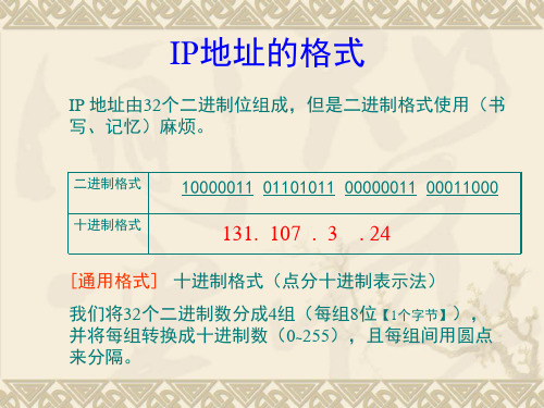
IP地址的格式
IP地址的正确写法为:X.X.X.X(仅指 IPv4)
IP地址基础知识
最新版整理ppt
网络技术IP地址.pptx

32位
网络号
主机号
网络号位数影响这类网络的个数 主机号位数影响每一个该类网络所容纳的主机数量
2.IP地址分类
A类
网络号 8位
主机号 24位
0
第一位固定是“0”,则第一个八位
最小0 0000000 0 最大0 1111111 127
2.IP地址分类
可以看出,A类地址理论上有128个,实际网络号为 “0”和“127”两种不能用,则A类网络最多有126个。
2.IP地址分类
B类
网络号 16位
主机号 16位
10
前两位固定是“10”,则第一个八位
最小10 000000 128 最大10 111111 191
2.IP地址分类
可以看出,大约有214个B类IP地址。 一个B类地址理论上可以容纳主机数量为216个,大约 是6万5千余台,实际主机号全“0”和全“1”不可以分配 给主机,则一个B类网络上可以容纳主机数量为216-2个。主 机号全“0”,代表该网络的网络地址,主机号全“1”代 表该网络的广播地址,这两个地址不能分配给计算机。 B类地址设计的初衷就是针对超大型公司使用,所以个 数比A类要多,但是每一个可容纳主机数量比A类少。
3.IP地址与网络地址
我们经常有如下说法,例如“我的IP地址是192.168.2.1”, 但还有一种说法是“给我们公司分配了一个192.168.2.0的C类 地址” 。这里出现了两个地址的概念,有什么区别呢?
3.IP地址与网络地址
192.168.2.1 是192.168.2.0这个C类地址里的一个IP地址;由 于192开头的属于C类地址,C类地址主机号是8位,而192.168.2.0 中的主机号8位全是“0”,它就是一个C类的网络地址,里面包含 了若干个IP地址。
IP地址基础ppt课件

给每一个物理网络分配一个网络标识会使路由器和主机上的路由表 变得太大,因而使网络性能变坏。
两级的IP地址不够灵活,很难针对不同的网络需求进行规划和管理。
32
子网划分
子网 子网(Subnet)是在TCP/IP网络上,用路由器连接的网段。
同一子网内的IP地址必须具有相同的网络标识。
33
子网划分
子网掩码 通常在设置IP地址的时候,必须同时设置子网掩码,子网
掩码不能单独存在,它必须结合IP地址一起使用。子网掩码只 有一个作用,就是将某个IP地址划分成网络标识和主机标识两 部分。
20
IP地址分类-私有地址
私有IP地址包括以下地址段: ➢ 10.0.0.0/8
10.0.0.0/8私有网络是A类网络,允许有效IP地址范围从 10.0.0.1 至 10.255.255.254。10.0.0.0/8私有网络有24位主机 标识。 ➢ 172.16.0.0/12
172.16.0.0/12私有网络可以被认为是16位B类网络,20位 可分配的地址空间(20位主机标识),能够应用于私人组织里 的任一子网方案。172.16.0.0/12私有网络允许下列有效的IP地 址范围:172.16.0.1 至 172.31.255.254。 ➢ 192.168.0.0/16
IP地址组件:网络号和主机号 ➢ 网络号:唯一地标识网络中的某个网段 ➢ 主机号:唯一地标识网络网络上的某台设备 网络号和主机号的组合必须在整个网络中唯一 主机地址子组件:网络地址、主机地址和定向广播地址 ➢ 网络地址:网络号中的第一个地址 ➢ 定向广播地址:网络号中最后一个地址 ➢ 主机地址:网络地址和定向广播地址之间的所有地址
《IP地址及其》课件
IP地址的重要性
1 唯一标识
IP地址是网络中各设备的唯一标识。
3 通信基础
IP地址是计算机网络通信的基础。
2 位置决定
IP地址决定设备在网络中的位置。
IP地址的获取
1 动态获取
动态获取IP地址是一种自动分配的方式,适用于大型网络或者网络中设备频繁更换的场景。
IP地址及其 PPT课件
在本次课程中,我们将深入探讨IP地址的概念、分类和获取方式,以及如何保 护这个网络中最重要的资源。让我们开始吧!
什么是IP地址?
1 定义
IP地址是用于在网络上识别主机位置的数字标识符。
2 构成
IP地址由32位二进制数构成,通常以点分十进制格式表示。
IP地址的分类
五类地址
IP地址按照地址分配的方式分为五类,从A到E。
感谢收听
谢谢您的耐心聆听,希望本次课程能够对您有所帮助,祝您工作愉快!
2 静态获取
静态获取IP地址是一种手动分配的方式,适用于小型网络或者网络中设备变更较少的场景。
IP地址的保护
1
审计
对IP地址进行监控和审计,及时发现和解决异常情况。
2
分配控制
对IP地址的分配进行控制,保证每个设备都有唯一的IP地址。
3
加密保护
对IP地址进行信息加密,防止非授权用户的恶意攻击。
总结
重要资源
IP地址是网络中最重要的资源之一,是计算机网络通信的基础。
关键知识
了解IP地址的分类、获取和保护对于网络管理者至关重要。
灵活运用
在实际工作中,我们需要灵活运用IP地址,合理分配、使用和管理网络资源。
《IP地址基础知识》课件

获取方式
申请者可以通过购买、租赁或免费 获取IP地址,具体方式根据不同机 构的规定而有所不同。
注意事项
申请者在申请和获取IP地址时,需 要遵守相关规定和法律法规,确保 合法使用IP地址。
IP地址的使用方式
公网IP地址
用于标识互联网上的每一台设备,实现设备之间的通信。
私有IP地址
用于局域网内部通信,可以在一定范围内自由分配和使用 。
PAT通过将内部网络中的IP地址 和端口号进行映射,实现多个内 部主机使用同一个公共IP地址与
外部通信。
PAT可以有效地节省公共IP地址 资源,尤其在IP地址短缺的情况
下非常有用。
NAT与PAT的区别与联系
区别
NAT技术只进行IP地址的转换,而PAT技术除了进行IP地址转换外,还进行端口 号的转换。NAT通常只允许一个内部主机访问外部网络,而PAT允许多个主机共 享一个公共IP地址。
NAT技术
通过将一个公网IP地址映射到多个私有IP地址的方式,实 现多台设备共享一个公网IP地址。
VPN技术
通过虚拟专用网络的方式,实现远程用户访问公司内部网 络资源时使用公司提供的公网IP地址。
03 IP地址的私有与公有
私有IP地址
私有IP地址定义
私有IP地址是指在本地 局域网内部使用的IP地 址,无法在互联网上直 接访问。
IPv4向IPv6过渡的方式与策略
过渡方式
IPv4向IPv6过渡需要采用双栈技术、隧道技术和翻译技术等方案,实现IPv4和IPv6之间的互通。
过渡策略
政府和企业应积极推动IPv6的部署和应用,制定合理的过渡计划和技术方案,逐步将现有的IPv4网络升级为IPv6 网络。
THANKS
IP网络技术培训课件

终端设备故障
计算机、手机等终端设备无法连接到网络。
交换机故障
交换机端口异常、配置错误或设备损坏等。
网络连接故障
无法正常访问外部网站或内部服务器。
故障排查工具介绍
网络测试仪
用于检测网络线路的连通性和信号质量。
网络分析软件
用于抓取网络数据包,分析网络流量和协议状态。
02
IP地址与子网划分
IP地址基础
1 2
IP地址概念
IP地址是互联网中用于标识和定位设备的唯一地 址。
IP地址分类
IP地址分为五类,分别是A、B、C、D和E类,其 中常用的是A、B和C类。
3
IP地址表示法
IP地址通常采用点分十进制表示法,例如 192.168.1.1。
子网划分原理
子网掩码概念
01
IP网络的应用场景
总结词
IP网络技术的应用场景十分广泛,包括但不限于云计 算、大数据、物联网、远程办公、在线教育等领域。
详细描述
IP网络技术的应用场景非常广泛,涵盖了各个领域。 在云计算领域,IP网络技术是实现云计算服务的基础 设施之一,用于连接云端和用户之间的数据传输和通 信。在大数据领域,IP网络技术用于传输和处理海量 数据,提高数据处理效率。在物联网领域,IP网络技 术可以实现各种智能设备的互联互通,促进物联网应 用的发展。在远程办公领域,IP网络技术可以实现远 程视频会议、文件传输和在线协作等功能,提高办公 效率。在线教育领域,IP网络技术可以提供在线课程 、远程教育和直播教学等服务,促进教育资源的共享 和普及。此外,IP网络技术还广泛应用于金融、医疗 、物流等领域,推动着各行业的数字化转型和创新发
ip地址教学PPT课件

11 00000010
很明显,这些数字对于人来说不太好记忆。人们为了方便记忆,
就将组成计算机的IP地址的32位二进制分成四段,每段8位,中间用
小数点隔开,然后将每八位二进制转换成十进制数,这样上述计算
机的IP地址就变成了:210.73.140.2址的分类
我们说过因特网是把全世界的无数个网络连接起来的一个庞大的网
间网,每个网络中的计算机通过其自身的IP地址而被唯一标识的, 据此我们也可以设想,在INTERNET上这个庞大的网间网中,每个
网络也有自己的标识符。这与我们日常生活中的电话号码很相像,
例如有一个电话号码为0515163,这个号码中的前四位表示该电话是
属于哪个地区的,后面的数字表示该地区的某个电话号码。与上面
110***** ******** ******** ******** 192-223 0-255 0-255 1-254 IP地址范围为: 192.x.y.z~223.x.y.z。
I2n02t0/e10r/1n3 et有2054512个C类地址。
9
IP地址的分类
D类地址用于多点播送。
第一个字节以“lll0”开始,第一个字 节的数字范围为224~239,是多点播送地
10****** ******** ******** ******** 128一191 0-255 0-255 1-254 IP地址范围为: 128.x.y.z~191.x.y.z
I2n02t0/e10r/1n3 et有16256个B类地址。
8
IP地址的分类
C:这类地址的特点是以110开头,第 一、二、三字节表示网络号,第四字节表 示网络中的主机号,网络数量比较多,可 以有2097152个网络号,每一网络中最多可 以有254个主机号。(小型网络,如校园网)
ip地址ppt课件

更好的移动性
IPv6在设计时斟酌了安全性,包括更好的加 密和身份验证机制,增强了网络通讯的安全 性。
更好的服务质量
IPv6提供了更多的服务质量控制和路由机制 ,可以更好地满足实时应用的需求。
IPv6的不足
兼容性问题
IPv6与IPv4不兼容,需 要进行过渡和转换,增 加了部署和实施的复杂
性。
装备支持不足
公道分配IP资源
根据实际需求公道分配IP 地址,避免IP地址浪费。
子网划分的方法
确定子网掩码
根据需求选择合适的子网掩码, 用于标识子网和主机。
测试与验证
进行测试和验证,确保子网划分 正确且网络运行正常。
01
按需求分析
第一分析网络需求,确定需要划 分的子网数量和每个子网的规模 。
02
03
04
配置路由和交换机
DHCP服务器配置
安装DHCP服务
依照服务器软件的说明进 行安装和配置。
配置租约期限
可以设置IP地址租约的时 间长度,以控制地址的回
收和重新分配。
01
02
03
04
05
选择合适的服务器软件
如Windows Server、 Linux等。
创建地址池
根据需求设置IP地址范围 、子网掩码、默认网关等
参数。
用哪种协议。
隧道策略
通过将IPv4包封装在IPv6包中 进行传输,实现IPv4和IPv6之 间的通讯。
NAT64策略
使用NAT-PT(网络地址转换协 议转换)技术,将IPv6地址转 换为IPv4地址,反之亦然。
应用层网关策略
在应用层进行协议转换,实现 不同协议之间的通讯。
感谢您的观看
Lab3-IP地址功能A计算机网络实训课件
9 主讲教师:彭城
3 主讲教师:彭城
计算机网络技术及应用
实验步骤
• 实验要求: 实验要求:
– 四个同学为一组(建议临近同学自组),选择组 四个同学为一组(建议临近同学自组), ),选择组 长一名; 长一名; – 启动桌面虚拟机(win2003)系统; 启动桌面虚拟机( )系统; – 在虚拟机系统内设置 地址等相关实验内容。 在虚拟机系统内设置IP地址等相关实验内容 地址等相关实验内容。
(其余同学也可作组长相同的操作,并进行相同的验证访问) 其余同学也可作组长相同的操作,并进行相同的验证访问)
7 主讲教师:彭城
计算机网络技术及应用
实验提示
• 在访问共享文件夹期间可建议如下监控
• 在“计算机管理”窗口德 “共享文件夹”选项中, 共享文件夹”选项中, 计算机管理” 可以看到“共享” 会话” 打开文件”选项。 可以看到“共享”、“会话”和“打开文件”选项。 • “共享”选项显示出本机所有共享文件夹的列表, 共享”选项显示出本机所有共享文件夹的列表, 并且可确定当前共享文件夹的并发连接数 。
5 主讲教师:彭城ຫໍສະໝຸດ 计算机网络技术及应用实验步骤
同组内成员相互Ping测试,检查连通性; 测试,检查连通性; 同组内成员相互 测试 回顾上学期知识):每位同学在win2003上建 ):每位同学在 (回顾上学期知识):每位同学在 上建 立三个文件夹, 立三个文件夹,在本组内分别使用下面三种方式 相互共享互访对方的三个文件夹: 相互共享互访对方的三个文件夹: 1. 通过“网上邻居”连接到共享文件夹 通过“网上邻居” 2. 通过“UNC”路径连接到共享文件夹 通过“ 路径连接到共享文件夹 • •
4 主讲教师:彭城
计算机网络技术及应用
完美讲解IP地址的PPT课件

子网掩码 1的数量
CIDR表示的 IP地址
8 + 8 + 4 + 0 = 20
10.217.123.7/20
26
IP地址聚合设计
IP地址聚合,就是把两个小网络合并为一个大 网络,主要是通过修改子网位实现。通俗点说 就是合为一个网段。
要计算IP地址聚合后的地址,其实就是比较几 个IP的网络前缀,相同的部分有多少位,这多 少位就是聚合后的IP,子网掩码就是把相同的 网络前缀变为1,剩下的为0,算出十进制就可 以了。
子网的划分
思考2:
假设一个公司网络内有60000台主机,此时分配一 个B类网IP地址是足够的,但这样会带来什么样的 问题?
带来的问题:
一个B类网络可以容纳的主机数量为65534,但整 个网络处于同一个广播域,如果有大量的广播信息 存在,将会导致网络拥塞上
17
划分子网的目的
如果我们将一个网络划分成若干个子网,会有 以下的好处:
第一,IP 地址管理机构在分配 IP 地址时只分配网络 号,而剩下的主机号则由得到该网络号的单位自行分 配。这样就方便了 IP 地址的管理。
第二,路由器仅根据目的主机所连接的网络号来转发 分组(而不考虑目的主机号),这样就可以使路由表 中的项目数大幅度减少,从而减小了路由表所占的存 储空间。
9
IP 地址的一些重要特点
(2) 实际上 IP 地址是标志一个主机(或路由器)和一 条链路的接口。
当一个主机同时连接到两个网络上时,该主机就必须 同时具有两个相应的 IP 地址,其网络号 net-id 必须 是不同的。这种主机称为多接口主机 (multihomed host)。
由于一个路由器至少应当连接到两个网络(这样它才 能将 IP 数据报从一个网络转发到另一个网络),因 此一个路由器至少应当有两个不同的 IP 地址。
IP地址讲课课件.
。
❖ 因此,D类地址的第1个八位组的最大值: 11101111(转换成十进制数为239),最小值 11100000(转换成十进制为224)。
❖ 任何IP地址的第一个八位组的取值范围在224-239之间的都是D类地址。
E类地址
❖ Internet工程任务组保留E类地址作为研究使用 。因此,Internet上没有发布E类地址使用。
16777214(2242)
B类 10 128-191 网.网.主.主 16384(214) 65534(216-2)
C类 110
192-223
网.网.网.主
2097152(2 21)
254(28-2)
D类 1110 224-239 组播地址
E类 1111 240-255 研究和实验用地址
提示:
主机号不能为全“1”(主机号为全“1”是广播地址);
❖ 因此,第1个八位组的最大值:11011111( 转换成十进制数为223),最小值11000000 (转换成十进制为192)。
❖ 任何IP地址的第一个八位组的取值范围在 192--223之间的都是C类地址。
D类地址
❖ D类地址用来支持组播。 ❖ 组播地址是一组网络地址,用来转发目的地
址为预先定义的一组IP地址的分组。 ❖ 因此,一台工作站可以将单一的数据流传送
模板中的图片展示页面,您可以根据需要
方法一:更改图片
2. 在图“替换”下拉列表中选择要更改字体。(如下图)
1.选中模版中的图片(有些图片与其他对 ,而不是组合)。
2.单击鼠标右键,选择“更改图片”,选
3. 在“替换为”下拉列表中选择替换字体。 4. 点击“替换”按钮,完成。
ip地址课件
ip地址课件IP地址课件IP地址是互联网中非常重要的一项技术,它是互联网通信的基础。
在这个信息爆炸的时代,我们每天都在使用互联网,但是对于IP地址的了解却不够深入。
为了帮助大家更好地理解IP地址,我准备了一份IP地址课件,让我们一起来学习吧!第一部分:IP地址的概念和作用IP地址全称为Internet Protocol Address,它是互联网上每个设备的唯一标识符。
就像我们在现实生活中有门牌号一样,每个设备在互联网上都有一个独一无二的IP地址。
IP地址的作用是用于在互联网上进行通信和数据传输。
无论是发送电子邮件、浏览网页还是进行在线游戏,都需要通过IP地址进行连接和交流。
第二部分:IP地址的分类IP地址分为IPv4和IPv6两种类型。
IPv4是目前广泛使用的IP地址版本,它由32位二进制数表示,例如192.168.0.1。
IPv4地址的数量有限,随着互联网的快速发展,IPv4地址已经不够用了。
为了解决这个问题,IPv6应运而生。
IPv6采用128位二进制数表示,例如2001:0db8:85a3:0000:0000:8a2e:0370:7334。
IPv6地址的数量极其庞大,可以满足未来互联网的需求。
第三部分:IP地址的组成IP地址由网络地址和主机地址两部分组成。
网络地址用于标识网络,主机地址用于标识具体的设备。
以IPv4为例,网络地址和主机地址的划分是根据子网掩码来进行的。
子网掩码决定了网络地址和主机地址的边界。
例如,对于IP地址192.168.0.1,子网掩码为255.255.255.0,前三个255表示网络地址,最后一个0表示主机地址。
第四部分:IP地址的获取方式在互联网上,我们可以通过两种方式来获取IP地址:静态IP地址和动态IP地址。
静态IP地址是由网络管理员手动分配给设备的,它不会改变。
静态IP地址适用于需要长期稳定连接的设备,例如服务器。
动态IP地址则是由DHCP (Dynamic Host Configuration Protocol)服务器自动分配的,它会在每次设备连接网络时进行更改。
Lab03

实验三 静态路由与默认路由的配置为互联网络中的路由器的每个接口设置适当的IP地址后,要使该互联网络中的每个网络之间能够相互通信,必须将互联网络中的每个网络添加到每个路由器的路由表中。
给路由器添加路由表有静态和动态的方式,本实验学习怎样在路由器上手工将网络添加到每个路由器的路由表中,并验证网络之间的连通性。
1.实验目的1)了解路由表在路由器进行数据包转发时所起的作用;2)理解路由器转发数据包的工作过程;3)学习在路由器上添加静态路由的方法;4)学习在路由器上添加默认路由的方法;5)学会在路由器上查看路由表;6)会进行网络连通性的检查。
2.实验环境计算机、若干台路由器组成的互联网络或Boson Netsim 6.0路由器、交换机模拟器软件3.实验要求与说明在实验图3-1所示的网络拓扑图中,给每台路由器添加静态路由,使每台路由器上都具有完整的路由表,使每个互联网之间都能够相互通信。
检查每个路由器上的路由表,并验证各个网络之间是否能够相互通信。
用默认路由取代路由器Router3上的静态路由,检查路由表,再验证各个网络之间是否能够相互通信。
通过实验,加深对静态路由和默认路由的理解。
实验图3-14.实验步骤(1) 按照实验图3-1所示的网络拓扑图连接网络设备(或在Boson Netsim 中调入网络拓扑图)。
(2) 给每个路由器设置适当的主机名及其他一些基本参数,并给每个路由器和PC机的接口设置如下表所示的IP地址,子网掩码全部为255.255.255.0。
接之间,必然有一台路由器充当DCE的角色,要给它设置时钟频率。
我们可以用show controllers命令检查接口是DTE还是DCE。
对充当DCE 的接口设置时钟频率。
(3) 检查路由器两两之间的连通性,如果没有问题,继续进行下面的实验。
(4) 给Router1设置适当的静态路由。
Router1#config tRouter1(config)#ip route 10.1.2.0 255.255.255.0 10.1.1.2Router1(config)#ip route 172.16.20.0 255.255.255.0 172.16.10.2Router1(config-if)#(5) 查看路由表,检查路由配置是否正确。
计算机网络技术应用实务电子课件——第6章 IP地址

172.17.32.126
···
172.17.32.125
172.17.32.32
172.17.20.131
172.17.15.20 ·
172.17.15.156 ··
172.17.15.0
172.17.20.53
172.17.20.54
子网
·
路由器
172.17.32.0
172.17.20.0
·
子网 ·· 172.17.20.82
子网
172.17.20.131
172.17.32.126
· · · 172.17.32.32
172.17.32.125
站点 172.17.0.0
2. 划分子网的原因
(1)充分使用地址 (2)划分管理职责 (3)提高网络性能
3. 子网划分的层次结构
(1)IP地址是一种层次型的编址方案。 通过划分子网,形成一个三层的结构,即网络号、
主机号
00110011
TCP/IP对子网掩码
IP地址:172.25.16.51 子网掩码:255.255.0.0
网络地址:172.25
和IP地址进行“按 位与”的操作。经 过按位与运算,可
以将每个IP地址的
网络地址取出,从
而知道两个IP地址
IP地址:172.25.16.51 所对应的网络。
子网掩码:255.255.255.0 网络地址:172.25.16
一台主机可以使用的有效的A类地址范围 00000001 00000000 00000000 00000001 ~ 01111110 11111111 11111111 11111110
1.0.0.1
126.255.255.254
Lab3 IPv4
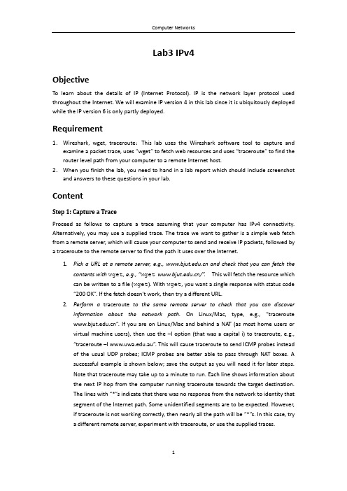
Lab3 IPv4ObjectiveTo learn about the details of IP (Internet Protocol). IP is the network layer protocol used throughout the Internet. We will examine IP version 4 in this lab since it is ubiquitously deployed while the IP version 6 is only partly deployed.Requirement1.Wireshark, wget, traceroute:This lab uses the Wireshark software tool to capture and examine a packet trace, uses “wget” to fetch web resources and uses “traceroute” to find the router level path from your computer to a remote Internet host.2.When you finish the lab, you need to hand in a lab report which should include screenshot and answers to these questions in your lab.ContentStep 1: Capture a TraceProceed as follows to capture a trace assuming that your computer has IPv4 connectivity. Alternatively, you may use a supplied trace. The trace we want to gather is a simple web fetch from a remote server, which will cause your computer to send and receive IP packets, followed by a traceroute to the remote server to find the path it uses over the Internet.1.Pick a URL at a remote server, e.g., and check that you can fetch thecontents with wget, e.g., “wget /”.This will fetch the resource which can be written to a file (wget). With wget, you want a single response with status code “200 OK”. If the fetch doesn’t work, then try a different URL.2.Perform a traceroute to the same remote server to check that you can discoverinformation about the network path.On Linux/Mac, type, e.g., “traceroute ”. If you are on Linux/Mac and behind a NAT (as most home users or virtual machine users), then use the –I option (that was a capital i) to traceroute, e.g., “traceroute –I .au”. This will cause traceroute to send ICMP probes instead of the usual UDP probes; ICMP probes are better able to pass through NAT boxes. A successful example is shown below; save the output as you will need it for later steps.Note that traceroute may take up to a minute to run. Each line shows information about the next IP hop from the computer running traceroute towards the target destination.The lines with “*”s indicate that there was no response from the network to identity that segment of the Internet path. Some unidentified segments are to be expected. However, if traceroute is not working correctly, then nearly all the path will be “*”s. In this case, trya different remote server, experiment with traceroute, or use the supplied traces.Figure 1: Running tracerouteunch Wireshark and start a capture with a filter of “tcp port 80“. Make sure to check“enable network name resolution”. We use this filter to record only standard web traffic.Name resolution will translate the IP addresses of the computers sending and receiving packets into names. It will help you to recognize whether the packets are going to or from your computer.Figure 2: Setting up the capture options4.After the capture is started, repeat the wget/curl command above. This time, the packetswill also be recorded by Wireshark.5.After the command is complete, return to Wireshark and stop the trace. You should nowhave a short trace similar to that shown in the figure below that contains the output of a traceroute you ran earlier to the corresponding server.Figure 3: Trace of wget traffic showing the details of the IP headerStep 2: Inspect the TraceSelect any packet in the trace and expand the IP header fields (using the “+” expander or icon) to see the details. You can simply click on a packet to select it (in the top panel). You will see the details of its structure (in the middle panel) and the bytes that make up the packet (in the bottom panel). Our interest is the IP header so that you may ignore the other higher and lower layer protocols. When you click on parts of the IP header, you will see the bytes that correspond to the part highlighted in the bottom panel. We have expanded the IP header and clicked on all the IP header fields in the figure above.Let us go over the fields in turn:∙The version field is set to 4. This is “IPv4” after all.∙Then there is the header length field. Observe by looking at the bytes selected in the packet data that version and header length are both packed into a single byte.∙The Differentiated Services field contains bit flags to indicate whether the packet should be handled with quality of service and congestion indications at routers.∙Then there is the Total Length field.∙Next is the Identification field, which is used for grouping fragments, when a large IP packet is sent as multiple smaller pieces called fragments. It is followed by the Flags and the Fragment offset fields, which also relate to fragmentation. Observe that they share bytes.∙Then there is the Time to live or TTL field, followed by the Protocol field.∙Next comes the header checksum. Is your header checksum carrying 0 and flagged as incorrect for IP packets sent from your computer to the remote server? On some computers, the operating system software leaves the header checksum blank (zero) for the NIC to compute and fill in as the packet is sent. This is called protocol offloading. It happens after Wireshark sees the packet, which causes Wireshark to believe that the checksum is wrong and flag it with a different color to signal a problem. A similar issue may happen for the TCP checksum. You can remove these false errors if they occur by telling Wireshark not to validate the c hecksums. Select “Preferences” in the Wireshark menus and expand the “Protocols” area. Look under the list until you come to IPv4.Uncheck “Validate checksum if possible”. Simil arly, you may uncheck checksum validation for TCP if applicable to your case.∙The last fields in the header are normally the source and the destination addresses. It is also possible to have IP options, but these are unlikely in standard web traffic.∙The IP header is followed by the IP payload. This makes up the rest of the packet, starting with the next higher layer header, TCP in our case, but not including any link layer trailer(e.g., Ethernet padding).Step 3: IP Packet StructureTo show your understanding of IP, sketch a figure of an IP packet you studied. It should show the position and size in bytes of the IP header fields as you can observe using Wireshark.Since you cannot easily determine sub-byte sizes, group any IP fields that are packed into the same bytes. Your figure can simply show the frame as a long, thin rectangle. Try not to look at the figure of an IPv4 packet in your text; check it afterwards to note and investigate any differences.To work out sizes, observe that when you click on a protocol block in the middle panel (the block itself, not the “+” expander), Wireshark will highlight the corresponding bytes in the packet in the lower panel, and display the length at the bottom of the window. You may also use the overall packet size shown in the Length column or Frame detail block. Note that this method will not tell you sub-byte positions.By looking at the IP packets in your trace, answer these questions:1.What are the IP addresses of your computer and the remote server?2.Does the Total Length field include the IP header plus IP payload, or just the IP payload?3.How does the value of the Identification field change or stay the same for differentpackets? For instance, does it hold the same value for all packets in a TCP connection or does it differ for each packet? Is it the same in both directions? Is there a pattern if the value does change?4.What is the initial value of the TTL field for packets sent from your computer? Is it themaximum possible value, or some lower value?5.How can you tell from looking at a packet that it has not been fragmented? Most often IPpackets in normal operation are not fragmented. But the receiver must have a way to be sure. Hint: you may need to read your text to confirm a guess.6.What is the length of the IP Header and how is this encoded in the header length field?Hint: notice that only 4 bits are used for this field, as the version takes up the other 4 bits of the byte. You may guess and check your text.Turn-in: Hand in your drawing of an IP packet and the answers to the questions above.Step 4: Internet PathsThe source and destination IP addresses in an IP packet denote the endpoints of an Internet path, not the IP routers on the network path that the packet travels from the source to the destination. traceroute is a utility for discovering this path. It works by eliciting responses (ICMP TTL Exceeded messages) from the router that is 1 hop away from the source towards the destination, then 2 hops away from the source, then 3 hops, and so forth until the destination is reached. The responses will identify the IP address of the router. The output from traceroute normally prints the information one hop per line including the measured round trip times and IP address and DNS names of the router. The DNS name is handy for working out the organization to which the router belongs. Since traceroute takes advantage of common router implementations, there is no guarantee that it will work for all routers along the path, and it is usual to see “*” responses when it fails for some portions of the path.Using the traceroute output, sketch a drawing of the network path. If you are using the supplied trace, note that we have provided the corresponding traceroute output as a separate file.Show your computer (left-hand side) and the remote server (right-hand side), both with IP addresses, as well as the routers along the path between them numbered by their distance on hops from the start of the path.You can find the IP address of your computer and the remote server on the packets in the trace that you captured. The output of traceroute will tell you the hop number for each router.To finish your drawing, label the routers along the path with the name of the real-world organization to which they belong. To do this, you will need to interpret the domain names of the routers given by traceroute. If you are unsure, label the routers with the domain name of what you take to be the organization. Ignore or leave blank any routers for which there is no domain name (or no IP address).This is not an exact science, so we will give some examples. Suppose that traceroute identifies a router along the path by the domain name . Normally, we can ignore at least the first part of the name, since it identifies different computers in the same organization and not different organizations. Thus we can ignore at least “arouter” in the domain name. For generic top-level domains, like “.com” and “.edu”, the last two domains give the domain name of the organization. So for our example, it is “”. To translate this domain name into the real-world name of an organization, we might search for it on the web. You will quickly find that is the University of Washington. This means that “cac” portion is an internal structure in the University of Washington, which is not important for the organization name. You would write “University of Washington” on your figure for any routers with domain names of the form *.Alternatively, consider a router with a domain name like .au. Again, we ignore at least the “arouter” part as it indicates a computer within a specific organization. For country-code top-level domains like “.au” (for Australia), the last three domains in the name will normally give the organization. In this case the organization’s domain name is .au.Using a web search, we find this domain represents AARNET, which is Australia’s r esearch and education network. The “syd” portion is internal structure, and a good guess is that it means the router is located in the Sydney part of AARNET. So, for all routers with domain names of the form *.au, you would write “AARNET” on your figure. While there are no guarantees, you should be able to reason similarly and at least give the domain name of the organizations near the ends of the path.Turn-in: Hand in your drawing and the traceroute output if it was not supplied to you.Step 5: IP Header ChecksumWe will now look at the IP header checksum calculation by validating a packet. The checksum algorithm adds the header bytes 16 bits at a time. It is computed so that re-computing the sum across the entire IP header (including the checksum value) will produce the result of zero. A complicating factor for us is that this is done using 1s complement arithmetic rather than 2s complement arithmetic that is normally used for computing. The steps below explain how to perform the necessary computation.From the trace, pick a packet sent from the remote server to your computer and check that you have a non-zero value in the checksum field. The checksum value sent over the network will be non-zero, so if you have a zero value it is because of the capture setup. Try a packet that has an IP header of 20 bytes, the minimum header size when there are no options, to make this exercise easier.Follow these steps to check that the checksum value is correct:1.Divide the header into 10 two byte (16 bit) words. Each word will be 4 hexadecimal digitsshown in the packet data panel in the bottom of the Wireshark window, e.g., 05 8c2.Add these 10 words using regular addition. You may add them with a hexadecimalcalculator (Google to find one), or convert them to decimal, add them, and convert them back to hexadecimal. Do whatever is easiest.3.To compute the 1s complement sum from your addition so far, take any leading digits(beyond the 4 digits of the word size) and add them back to the remainder. For example: 5a432 will become a432 + 5= a437.4.The end result should be 0xffff. This is actually zero in 1s complement form, or moreprecisely 0xffff is -0 (negative zero) while 0x0000 is +0 (positive zero).If you cannot get your sum to come out and are sure that the checksum must be wrong, you can get Wireshark to check it. See whether it says “[correct]” already. If it doesn’t, then use the menus to go to Preferences, expand Protocols, choose IPv4 from the list, and chec k “validate header checksum”. Now Wireshark will check the checksum and tell you if it is correct.Turn-in: Hand in your sums. Next to each word you should note the IPv4 fields to which it corresponds.。
Lab 3 - IP Addressing
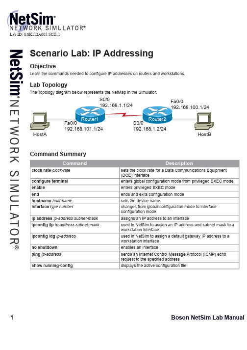
Subnet Mask
255.255.255.0 255.255.255.0 255.255.255.0 255.255.255.0 255.255.255.0 255.255.255.0
Default Gateway
192.168.101.1 192.168.100.1
Lab Tasks
1. Congure Router1 with a host name of Router1 . Congure the appropriate IP addresses on the interfaces; refer to the IP Addresses table. A DCE cable is connected to Router1. The Serial link should have a speed of 64 Kbps. 2. Congure Router2 with a host name of Router2 . Congure the appropriate IP addresses on the interfaces; refer to the IP Addresses table.
Interface
FastEthernet 0/0 Serial 0/0 FastEthernet 0/0 Serial 0/0 -
IP Address
192.168.101.1 192.168.1.1 192.168.100.1 192.168.1.2 192.168.101.2 192.168.100.2
Fa0/0 192.168.100.1/24
HostB
Command Summary
Command
- 1、下载文档前请自行甄别文档内容的完整性,平台不提供额外的编辑、内容补充、找答案等附加服务。
- 2、"仅部分预览"的文档,不可在线预览部分如存在完整性等问题,可反馈申请退款(可完整预览的文档不适用该条件!)。
- 3、如文档侵犯您的权益,请联系客服反馈,我们会尽快为您处理(人工客服工作时间:9:00-18:30)。
7 主讲教师:彭城
计算机网络技术及应用
实验提示
• 在访问共享文件夹期间可建议如下监控
• 在“计算机管理”窗口德 “共享文件夹”选项中, 共享文件夹”选项中, 计算机管理” 可以看到“共享” 会话” 打开文件”选项。 可以看到“共享”、“会话”和“打开文件”选项。 • “共享”选项显示出本机所有共享文件夹的列表, 共享”选项显示出本机所有共享文件夹的列表, 并且可确定当前共享文件夹的并发连接数 。
8 主讲教师:彭城
计算机网络技术及应用
实验思考题
• 通过本实验,你的对Ip Address的认识是 通过本实验,你的对 的认识是 什么? 什么? • 简要分析 Address与MAC Address的关 简要分析IP 与 的关 系。 • 你是网吧网管人员,你会如何管理计算机, 你是网吧网管人员,你会如何管理计算机, 如何划分Ip地址? 如何划分 地址? 地址
UNC路径的标准格式为:\\servername\sharename 路径的标准格式为: 路径的标准格式为
3. 通过“网络驱动器映射”连接到共享文件夹 通过“网络驱动器映射”
(注意组内同学,可在文件夹内存放不同文件用于相 注意组内同学, 互访问验证) 互访问验证)
6 主讲教师:彭城
计算机网络技术及应用
5 主讲教师:彭城
计算机网络技术及应用
实验步骤
同组内成员相互Ping测试,检查连通性; 测试,检查连通性; 同组内成员相互 测试 回顾上学期知识):每位同学在win2003上建 ):每位同学在 (回顾上学期知识):每位同学在 上建 立三个文件夹, 立三个文件夹,在本组内分别使用下面三种方式 相互共享互访对方的三个文件夹: 相互共享互访对方的三个文件夹: 1. 通过“网上邻居”连接到共享文件夹 通过“网上邻居” 2. 通过“UNC”路径连接到共享文件夹 通过“ 路径连接到共享文件夹 • •
计算机网络技术及应用
Lab_3
IP地址功能初识 地址功能初识
1 主讲教师:彭城
计算机网络技术及应用
实验简要介绍
• IP地址对计算机网络建立和运行具有极 地址对计算机网络建立和运行具有极 地址 其重要的作用, 其重要的作用,本次实验初步认识和分 地址功效, 析IP地址功效,为下次课程和后续实验 地址功效 提供引导作用。 提供引导作用。 • 通过本实验,实验者能够: 通过本实验,实验者能够:
3 主讲教师:彭城
计算机网络技术及应用
实验步骤
• 实验要求: 实验要求:
– 四个同学为一组(建议临近同学自组),选择组 四个同学为一组(建议临近同学自组), ),选择组 长一名; 长一名; – 启动桌面虚拟机(win2003)系统; 启动桌面虚拟机( )系统; – 在虚拟机系统内设置 地址等相关实验内容。 在虚拟机系统内设置IP地址等相关实验内容 地址等相关实验内容。
9 主讲教师:彭城
4 主讲教师:彭城
计算机网络技术及应用
实验提示
• 检查虚拟机菜单设置【vm】 [settings] 检查虚拟机菜单设置【 】 [network adapter] 是否已设为 是否已设为bridged模式 模式 • 每小组 地址设置为: 每小组IP地址设置为 地址设置为: 192.168.组长学号后两位 组长学号后两位.X 组长学号后两位 子网掩码( 子网掩码(submask)为:255.255.255.0 ) ——其中 为每位同学学号后两位 其中X为每位同学学号后两位 其中
– 了解 地址设置及其特点; 了解IP地址设置及其特点 地址设置及其特点; – 了解组建局域网络逻辑概念; 了解组建局域网络逻辑概念; – 掌握 地址与网络日常部分功能的关系。 掌握IP地址与网络日常部分功能的关系 地址与网络日常部分功能的关系。
2 主讲教师:彭城
计算机网络技术及应用
实验目的
• • • 掌握如何设置IP地址与掩码。 掌握如何设置 地址与掩码。 地址与掩码 学会验证IP地址与网络的功能 地址与网络的功能。 学会验证 地址与网络的功能。 回顾办公及学习中的部分局域网功能。 回顾办公及学习中的部分局域网功能。Fra bibliotek实验分析
• 每组组长更改本机 每组组长更改本机win2003 IP地址为: 地址为: 地址为 192.168.250.学号后两位 学号后两位 组内同学ping测试及再次访问组长之前共享文件, 测试及再次访问组长之前共享文件, 组内同学 测试及再次访问组长之前共享文件 查看结果,思考结果可能的原因? 查看结果,思考结果可能的原因? • 每组组长恢复原来IP,再将掩码(sunmask)改 每组组长恢复原来 ,再将掩码( ) 为:255.255.255.192 组内同学ping测试及再次访问组长之前共享文件, 测试及再次访问组长之前共享文件, 组内同学 测试及再次访问组长之前共享文件 查看结果,思考结果可能的原因? 查看结果,思考结果可能的原因?
