S7-PLC SIM使用入门手册
PLC_SIM使用
一、引言PLC的用户程序设计好后,要用实际的PLC硬件来调试。
但以下情况则需要对程序进行仿真调试:①控制设备不在本地,设计者需对程序进行修改和调试;②程序设计好后,PLC硬件尚未购回;③在实际系统中进行某些调试有一定风险。
为了解决这些问题,一些PLC生产厂家提供了可代替PLC硬件调试的仿真软件,本文主要介绍西门子公司的S7一PLCSIM仿真软件。
二、S7-PLCSIM概述1、S7-PLCSIM的主要功能(1)仿真软件还可模拟对位存储器、外围输入变量区和外围输出变量区的操作,以及对存储在数据块中的数据(如DBl.DBX0.0或DBl.DBW0等)的读写。
(2)可实现定时器和计数器的监视和修改,通过程序使定时器自动运行或手动复位。
(3)可对S7-300和S7-400 PLC的用户程序进行离线仿真与调试,可访问模拟PLC的I/O存储器、累加器和寄存器。
通过在仿真运行窗口中改变输入变量的ON/OFF状态来控制程序的运行,并观察有关输出变量的状态来监视程序运行的结果。
(4)可在仿真PLC中使用中断组织块测试程序的特性,并记录一系列操作事件及回放记录,从而自动测试程序。
2、S7-PLCSIM的主要组成部分(1)仿真PLCS7-PLCSIM用仿真PLC来模拟实际PLC的运行,用户可通过视图对象来调试程序。
它提供的多种视图对象可实现对仿真PLC内的各种变量、计数器和定时器的监视与修改。
(2)视图对象①CPU视图对象开始新仿真时,将自动出现CPU视图对象,用户可用单选框来选择运行、停止和暂停工作方式;MRES按钮用来复位存储器、删除块和删除仿真PLC中的硬件设置。
LED指示灯“SF'’表示软硬件错误;“RUN”与“STOP”表示运行与停止状态;“DP”(分布式外设或远程I/O)指示PLC与分布式外设或远程I/O的通信状态;“DC”(直流电源)指示电源的通断情况。
②插入视图对象输入变量(I)、输出变量(Q)和位存储器(M)视图对象分别用于访问和监视相应的数据区,可以以位、二进制、十进制、十六进制、字符及字符串的形式访问。
S7-PLCSIM V16在线帮助说明书
SIMATIC工程工具S7-PLCSIM V16 在线帮助编程和操作手册Siemens AG Digital Industries Postfach 48 4890026 NÜRNBERG 文档订购号: A5E46238796-AA Ⓟ 11/2019 本公司保留更改的权利Copyright © Siemens AG 2019. 保留所有权利法律资讯警告提示系统为了您的人身安全以及避免财产损失,必须注意本手册中的提示。
人身安全的提示用一个警告三角表示,仅与财产损失有关的提示不带警告三角。
警告提示根据危险等级由高到低如下表示。
危险表示如果不采取相应的小心措施,将会导致死亡或者严重的人身伤害。
警告表示如果不采取相应的小心措施,可能导致死亡或者严重的人身伤害。
小心表示如果不采取相应的小心措施,可能导致轻微的人身伤害。
注意表示如果不采取相应的小心措施,可能导致财产损失。
当出现多个危险等级的情况下,每次总是使用最高等级的警告提示。
如果在某个警告提示中带有警告可能导致人身伤害的警告三角,则可能在该警告提示中另外还附带有可能导致财产损失的警告。
合格的专业人员本文件所属的产品/系统只允许由符合各项工作要求的合格人员进行操作。
其操作必须遵照各自附带的文件说明,特别是其中的安全及警告提示。
由于具备相关培训及经验,合格人员可以察觉本产品/系统的风险,并避免可能的危险。
按规定使用 Siemens 产品请注意下列说明:警告Siemens 产品只允许用于目录和相关技术文件中规定的使用情况。
如果要使用其他公司的产品和组件,必须得到 Siemens 推荐和允许。
正确的运输、储存、组装、装配、安装、调试、操作和维护是产品安全、正常运行的前提。
必须保证允许的环境条件。
必须注意相关文件中的提示。
商标所有带有标记符号 ® 的都是 Siemens AG 的注册商标。
本印刷品中的其他符号可能是一些其他商标。
siemens s7 plc 配置网络安全指南 2018说明书

SIMATICProcess Control System PCS 7 Configuration Symantec Endpoint Protection V14Commissioning Manual03/2018A5E44395521-AALegal informationWarning notice systemThis manual contains notices you have to observe in order to ensure your personal safety, as well as to preventdamage to property. The notices referring to your personal safety are highlighted in the manual by a safety alertsymbol, notices referring only to property damage have no safety alert symbol. These notices shown below aregraded according to the degree of danger.DANGERindicates that death or severe personal injuryWARNINGindicates that death or severe personal injury may result if proper precautions are not taken.CAUTIONindicates that minor personal injury can result if proper precautions are not taken.NOTICEindicates that property damage can result if proper precautions are not taken.If more than one degree of danger is present, the warning notice representing the highest degree of danger will beused. A notice warning of injury to persons with a safety alert symbol may also include a warning relating to propertydamage.Qualified PersonnelThe product/system described in this documentation may be operated only by personnel qualified for the specifictask in accordance with the relevant documentation, in particular its warning notices and safety instructions. Qualifiedpersonnel are those who, based on their training and experience, are capable of identifying risks and avoidingpotential hazards when working with these products/systems.Proper use of Siemens productsNote the following:WARNINGSiemens products may only be used for the applications described in the catalog and in the relevant technicaldocumentation. If products and components from other manufacturers are used, these must be recommended orapproved by Siemens. Proper transport, storage, installation, assembly, commissioning, operation andmaintenance are required to ensure that the products operate safely and without any problems. The permissibleambient conditions must be complied with. The information in the relevant documentation must be observed. TrademarksAll names identified by ® are registered trademarks of Siemens AG. The remaining trademarks in this publicationmay be trademarks whose use by third parties for their own purposes could violate the rights of the owner. Disclaimer of LiabilityWe have reviewed the contents of this publication to ensure consistency with the hardware and software described.Since variance cannot be precluded entirely, we cannot guarantee full consistency. However, the information inthis publication is reviewed regularly and any necessary corrections are included in subsequent editions.Siemens AGDivision Process Industries and DrivesPostfach 48 4890026 NÜRNBERGGERMANYA5E44395521-AAⓅ 05/2018 Subject to changeCopyright © Siemens AG 2018.All rights reservedTable of contents1Security information (5)2Preface (7)3Configuration (9)3.1Introduction (9)3.2Notice (9)3.3Overview of SEP modules and functions (10)3.4SEP modules and functions (11)3.4.1General information (11)3.4.2Virus and Spyware Protection (11)3.4.3Intrusion Prevention (13)3.4.4Host Integrity (13)3.4.5Application and Device Control (13)3.4.6LiveUpdate (13)3.4.7Network Application Monitoring (14)Configuration Symantec Endpoint Protection V14Commissioning Manual, 03/2018, A5E44395521-AA3Table of contentsConfiguration Symantec Endpoint Protection V14 4Commissioning Manual, 03/2018, A5E44395521-AASecurity information1 Siemens provides products and solutions with industrial security functions that support thesecure operation of plants, systems, machines, and networks.In order to protect plants, systems, machines and networks against cyber threats, it isnecessary to implement – and continuously maintain – a holistic, state-of-the-art industrialsecurity concept. Siemens’ products and solutions constitute one element of such a concept.Customers are responsible for preventing unauthorized access to their plants, systems,machines and networks. Such systems, machines and components should only be connectedto an enterprise network or the internet if and to the extent such a connection is necessaryand only when appropriate security measures (e.g. firewalls and/or network segmentation) arein place.For additional information on industrial security measures that may be implemented, pleasevisit:https:///industrialsecuritySiemens’ products and solutions undergo continuous development to make them more secure.Siemens strongly recommends that product updates are applied as soon as they are availableand that the latest product versions are used. Use of product versions that are no longersupported, and failure to apply the latest updates may increase customer’s exposure to cyberthreats.To stay informed about product updates, subscribe to the Siemens Industrial Security RSSFeed underhttps:///industrialsecurity.Configuration Symantec Endpoint Protection V14Commissioning Manual, 03/2018, A5E44395521-AA5Security informationConfiguration Symantec Endpoint Protection V14 6Commissioning Manual, 03/2018, A5E44395521-AAPreface2 This documentation describes the settings of Symantec Endpoint Protection (SEP) that needto be changed for use in an industrial plant.The configuration represents an extract of the settings from SEP which were used in thecompatibility test with PCS 7 and WinCC.Important information about this whitepaperNoteThe recommended settings for these virus scanners have been chosen to ensure that thereliable real-time operation of PCS 7 is not adversely affected by the virus scanner software.These recommendations describe the currently known, best-possible compromise betweenthe objective of maximizing the detection and neutralization of virus software and malware andguaranteeing a highly deterministic time behavior of the PCS 7 process control system in alloperating phases.If you choose different settings for the virus scanner, this could have negative effects on thereal-time behavior.Purpose of the documentationThis documentation describes the recommended settings for virus scanner software incombination with PCS 7 and WinCC following the virus scanner installation.Required knowledgeThis documentation is aimed at persons involved in the engineering, commissioning, andoperation of automated systems based on SIMATIC PCS 7 or WinCC. Knowledge ofadministration and IT techniques for Microsoft Windows operating systems is assumed.In addition, readers should be familiar with the PCS 7 & WinCC security concept.Additional information is available on the Internet at the following address:Security concept (https:///WW/view/en/60119725) Configuration Symantec Endpoint Protection V14Commissioning Manual, 03/2018, A5E44395521-AA7PrefaceScope of the documentationThis documentation applies to process control systems that are realized with the correspondingPCS 7 or WinCC product version.NoteNote that certain virus scanners are only approved for certain product versions. Additionalinformation is available on the Internet at the following address:Compatibility tool (https:///kompatool)Configuration Symantec Endpoint Protection V14 8Commissioning Manual, 03/2018, A5E44395521-AAConfiguration3 3.1IntroductionSymantec Endpoint Protection (SEP) activates additional functions going beyond thetraditional virus scanner. The following configurations refer to the centrally managed SEPvariant, which is configured using the SEP Manager. The use of a local, non-managedinstallation is allowed, but is not described. In addition, only an English installation is referredto. All the configurations described are deviations from the default configurations, i.e. anysettings not described are not changed.3.2NoticeThe following setting is essential for stable operation of PCS 7.Under "Clients->My Company->Policies->External Communication Settings:UncheckClient Submission Send anonymous data to Sy‐mantecUncheckClient Queries Allow Insight lookups for threaddetectionWhen this option is active, the virus scanner attempts to contact Symantec Server directly onthe Internet during each file scan. There is a significant delay if the virus scanner cannot reachthe server. This makes the stable operation of PCS 7 impossible.All other check boxes under Submission Settings should also be cleared so that no internalinformation, even if it is anonymous, is sent to Symantec. The other options do not have anegative effect on PCS 7, however.Client RestartClients should never be restarted automatically. You should disable an automatic restart intwo places.Under "Clients->My Company->Policies->General:Restart Settings Restart method No restartGenerate a new policy under Install Packages->Client Install Settings:Restart Settings Restart method No restartConfiguration Symantec Endpoint Protection V14Commissioning Manual, 03/2018, A5E44395521-AA93.3Overview of SEP modules and functions SEP has the following configurable modules that can be configured with policies (available in the SEP under "Policies"):●Virus and Spyware Protection ●Firewall ●Intrusion Prevention ●Application and Device Control ●Host Integrity ●LiveUpdate ●Exceptions Additional settings (available in the SEP Manager under Clients > Policies > Location- independent Policies and Settings):●Custom Intrusion Prevention ●System Lockdown ●Network Application Monitoring The following modules and settings are recommended and are tested for compatibility for use in a PCS 7 and WinCC environment:●Virus and Spyware Protection ●Intrusion Prevention ●Device Control ●Host Integrity (provisional)●LiveUpdate ●Network Application Monitoring The following modules and settings are not recommended and are not checked in the compatibility test:●Firewall – Only the Windows Firewall is released for use with PCS 7 and WinCC as this is configured automatically depending on the product installed.●Application Control – This involves computer-specific settings that cannot be checked.●Exceptions – This involves system-specific settings that cannot be checked.●Custom Intrusion Prevention – This involves plant-specific settings that cannot be checked.●System Lockdown – This involves computer-specific settings that cannot be checked.For this reason, no policies should be assigned for these modules and the settings should not be switched "On". Any use of modules and settings which are not recommended is the user's own responsibility.Configuration3.3 Overview of SEP modules and functionsConfiguration Symantec Endpoint Protection V1410Commissioning Manual, 03/2018, A5E44395521-AA3.4SEP modules and functions3.4.1General informationThe options for the policies which have to be configured have no locks next to them. Werecommend that you "close" all locks (by clicking on them). This guarantees that theconfiguration of the virus scan client cannot be changed locally.For the same reason we recommend that you, under Clients-> Policies-> Location-specificSettings-> Client User Interface Control Settings: Click Server Control and Customize andclear all the check boxes except for "Display the client" and "Display the notification area icon".3.4.2Virus and Spyware ProtectionThe following configurations relate to a newly created Default Policy.Windows Settings-> ScheduledScans-> Scans->Administrator-De‐fined ScansDaily Scheduled Scan DeleteWindows Settings-> ProtectionTechnology-> Auto-Protect-> Ac‐tions-> Actions (for "Malicious" and"Security Risks")First action Leave alone (log only)Windows Settings-> ProtectionTechnology-> Auto-Protect-> Ac‐tions-> RemediationTerminate processes automatically UncheckWindows Settings-> ProtectionTechnology-> Auto-Protect-> Ac‐tions-> RemediationStop services automatically UncheckWindows Settings-> Protection Technology-> Auto-Protect-> Noti‐fications-> Notifications Display the Auto-Protect result dialogon the infected computerUncheckWindows Settings-> Protection Technology-> Download Protec‐tion-> Download Insight Enable Download Insight to detect po‐tential risk in downloaded files basedon file reputationUncheckWindows Settings-> ProtectionTechnology-> Download Protec‐tion-> Actions-> Malicious filesFirst action Leave alone (log only)Windows Settings-> ProtectionTechnology-> Download Protec‐tion-> Actions-> Unproven filesSpecify action for unproven files Leave alone (log only)Windows Settings-> Protection Technology-> Download Protec‐tion-> Notifications-> Notifications Display a notification message on theinfected computerUncheckWindows Settings-> ProtectionTechnology-> SONAR-> SONARSettingsEnable SONAR UncheckWindows Settings-> Email Scans-> Internet Email Auto-Protect->Scan DetailsEnable Internet Email Auto-Protect UncheckWindows Settings-> Email Scans-> Microsoft Outlook Auto-Protect-> Scan Details Enable Microsoft Outlook Email Auto-ProtectUncheckWindows Settings-> Email Scans-> Lotus Notes Email Auto-Protect-> Scan Details Enable Lotus Notes Email Auto-Pro‐tectUncheckWindows Settings-> Advanced Op‐tions-> Global Scan OptionsDisplay notifications about detections UncheckWindows Settings-> Advanced Op‐tions-> Quarantine-> General-> When New Virus Definitions Arrive Specify how client computers handleitems in the QuarantineDo NothingWindows Settings-> Advanced Op‐tions-> Quarantine-> General-> Quarantined Items Allow client computers to manuallysubmit quarantined items…UncheckWindows Settings-> Advanced Op‐tions-> Quarantine-> Cleanup-> Repaired Files Enable automatic deleting of backupfilesUncheckWindows Settings-> Advanced Op‐tions-> Quarantine-> Cleanup-> Backup Files Enable automatic deleting of repairedfilesUncheckWindows Settings-> Advanced Op‐tions-> Quarantine-> Cleanup-> Quarantined Files Enable automatic deleting of quaran‐tined files that could not be repairedUncheckWindows Settings-> Advanced Op‐tions-> Miscellaneous-> Notifica‐tions-> Notifications Display error messages with a URL toa solutionUncheck3.4.3Intrusion PreventionThe following configurations relate to a newly created Default Policy.No changes required.3.4.4Host IntegrityUsing "Host Integrity" you can monitor the configuration and the behavior of computers. Thismonitoring has to be configured specifically for the plant. Care should be taken to ensure thatno dialog boxes or messages appear on the local client.3.4.5Application and Device ControlThe following configurations relate to a newly created Default Policy.The recommendation is only to use Device Control, in order to prevent the use of USB devicesfor example.All check boxes should be cleared under "Application Control".3.4.6LiveUpdateThe following configurations relate to a newly created Default Policy.The settings for reaching the Symantec Update-Server on the internet or a higher-level updateserver must be adapted to the relevant network topology.Windows Settings-> Schedule-> Live‐Update SchedulingEnable LiveUpdate Scheduling UncheckWindows Settings-> Advanced Set‐tings-> User SettingsAllow the user to manually launch LiveUpdate UncheckWindows Settings-> Advanced Set‐tings-> User Settings Allow the user to modify HTTP, HTTPS, or FTPproxy settings for LiveUpdateUncheck3.4.7Network Application MonitoringThis setting should only be used by administrators with sound network and security knowledgeand in systems that have their own security administration.The setting "Network Application Monitoring" is under "Clients-> My Company-> Policies->Location-independent Policies and Settings-> Network Application Monitoring".The inheritance settings have to be changed here, depending on the company and networktopology.Network Application Monitoring Enable network application monitoring CheckNetwork Application Monitoring When an application change is detected Allow and Log。
第6章S7-200 PLC的功能指令及使用
Network 10 C10 +16 Network 11 C10
QB0
MOV_B EN ENO 7 IN OUT QB0
MOV_B EN ENO OUT
MOV_B EN ENO 3 IN OUT QB0
+18
MOV_B EN ENO OUT QB0
Network 12 C10 +20
MOV_B EN ENO 1 IN OUT QB0
字(整数INT)比较指令(取)
第一种 字比较触点“取”
字比较触点“取”
字(整数INT)比较指令(与)
第二种
字比较触点“与”
字比较触点“与”
字(整数INT)比较指令(或)
第三种 字比较触点“或”
字比较触点“或”
字(整数INT)比较指令(例题2)
例题2:分析程序,画出指定元件的时序
字比较指令例题2图
第一种:实数比较触点“取”
实数比较触点“取”
第二种:实数比较触点“与”
实数比较触点“与”
第三种:实数比较触点“或”
实 数 比 较 触 点 “ 或 ”
传送指令
1. 字节、字、双字、 实数的传送 SIMATIC功能指令助记符中最后的B、W、DW(或D)和R分别表 示操作数为字节(Byte)、字(Word)、双字(Doudle Word)和实数 (Real). 传送指令将输入的数据(IN)传送到输出(OUT),传送过程不改 变源地址中数据的值。
输入 启动开关 I1.0
输出 六盏灯 Q0.0-Q0.5
Network 1 I1.0 SM0.5 CU I1.0 R C10 24 Network 2 C10 +0 1 Network 3 C10 +2 3 Network 4 C10 +4 7 IN IN IN PV
西门子PLC入门基础学习基础
西门子PLC入门基础教程1、PLC基本概念可编程控制器(Programmable Controller)是计算机家族中的一员,是为工业控制而设计制造的。
早期的可编程控制器称作可编程逻辑控制器(Programmable Logic Controller),简称 PLC,它主要用来代替继电器实现逻辑控制。
随着技术的发展,这种装置的功能已经大大超过了逻辑控制的范围,因此,今天这种装置称作可编程控制器,简称PC。
但是为了避免与个人计算机(Personal Computer)的简称混淆,所以将可编程控制器简称PLC。
2、PLC的基本结构PLC实质是一种专用于工业控制的计算机,其硬件结构基本上与微型计算机相同。
A、中央处理器(CPU)中央处理器(CPU)是PLC的控制中枢。
他按照PLC系统成程序赋予的功能接收并存储从编程器键入的用户程序和数据;检查电源、存储器、I/O以及警戒定时器的状态,并能诊断用户程序中的语法错误。
当PLC投入运行时,首先他以扫描的方式接受现场各输入装置的状态和数据,并分别存入I/O映象区,然后从用户程序存储器中逐条读取用户程序,经过命令解释后,按指令的规定执行逻辑或数字运算的结果送入I/O映象区或数字寄存器内。
等所有的用户程序执行完毕之后,最后将I/O映象区的各输出状态或输出寄存器内的数据传送到相应的输出装置,如此循环运行,直到停止运行。
为了进一步提高PLC的可靠性,近年来对大型PLC还采用双CPU构成冗余系统,或采用三CPU的表决式系统。
这样即使某个CPU出现故障,整个系统仍能正常运行。
B、存储器存储系统程序的存储器称为系统存储器。
存储应用软件的存储器称为用户存储器。
{(一) PLC常用的存储器类型1. RAM (Random Assess Memory)这是一种读/写存储器(随机存储器),其存取速度最快,由锂电池支持。
2. EPROM (Erasable Programmable Read Only Memory)这是一种可擦除的只读存储器。
西门子S7-200PLC指令系统手册
(二)输出指令 梯形图(LAD)中,“()”表示线圈,“能 流”到线圈端,则线圈被激励,其Q寄存器的相 应位为1,反之为0; 语句表(STL)中,输出指令为“=”,把栈 顶值复制到操作数地址指定的存储器位(bit), 堆栈各级栈值不变。 (三)置位和复位指令-把从操作数(bit)指定 的地址开始的N个点都被置位或复位,其中N=1 -255
3. 修改指针:用自增或自减指令修改指针,则可 连续存取存储单元中的数据
五、用户程序的结构 用户程序可分为三个区:主程序、子程序和 中断程序; 主程序(OB1):是用户程序的主体,CPU 在每一个扫描周期都要执行一次主程序指令; 子程序:可选部分,只有主程序调用时才执 行; 中断程序:可选部分,只有当发生中断事件 时,才执行中断程序,可在扫描周期的任意点执 行。
(二)直接寻址-指令中直接给出操作数的地址 的寻址方式 例: 位寻址 AND Q5.5
字节寻址 ORB VB33 , LB21 字寻址 双字寻址 MOVW MOVD AC0 , AQW200 AC1 , VD200
(三)间接寻址-指令中给出了存放操作数地 址的存储单元的地址的寻址方式 1. 建立指针
S7-200 PLC 的SIMATIC指令集不支持完全 数据类型检查; 使用局部变量时,执行简单数据类型检查; 使用全局变量时,指令操作数为地址而不是 可选的数据类型时,执行无数据类型检查。 (二)数据长度和数值范围 数据长度:用字节型(B)、字型(W)、 双字型(D)分别表示8位、16位、32位数据; 不同的数据长度对应的数据范围如表5-4所示
在语句表(STL)中,没有EN允许输入端, 但允许执行指令的条件是栈顶的值必须为1。 功能框的ENO端是允许输出端,即允许功能 框的布尔量输出,用于指令的级联 ; 语句表(STL)中,用AENO(ANDENO)指 令产生允许输出。 (四)条件输入、无条件输入 条件输入:在梯形图(LAD)、功能块图 (FBD)中,与“能流”有关的功能框或线圈不直 接与左母线连接;
S7-200 SMART PLC 系统功能说明(图文并茂)

Page 1 of 58
存储卡
S 7 2 0 0S M A R TC P U支持商用M i c r o S D 卡(支持容量为4 G ,8 G ,1 6 G ):可用于程序传输,C P U 固件更新,恢复 C P U出厂设置。 打开C P U 本体数字量输出点上方的端子盖,可以看到右侧有一卡槽,将M i c r o S D 卡缺口向里插入,如图 1 所示:
S7-200 SMART 实时时钟
S 7 2 0 0S M A R T 的硬件实时时钟可以提供年、月、日、时、分、秒的日期/ 时间数据。 C P UC R 4 0A C / D C / R e l a y没有内置的实时时钟,C P US R 2 0 、C P US R 4 0 、C P US T 4 0 、C P US R 6 0 、C P US T 6 0 支持内置的实时时钟,C P U 断电 状态下可保持7 天。 S 7 2 0 0S M A R TC P US R 2 0 的时钟精度是± 1 2 0秒 /月,C P US R 4 0 、C P US T 4 0 、C P US R 6 0 、C P US T 6 0 的时钟精度是 1 2 0秒 /月。 S 7 2 0 0S M A R TC P U靠内置超级电容为实时时钟提供电源缓冲,保持时间为典型值7 天,最小值6 天。缓冲电源放电完毕后,再次上电后 时钟将停止在缺省值,并不开始走动。 注意:因为 C P UC R 4 0无内置超级电容,所以实时时钟无电源缓冲,尽管用户可以使用R E A D _ R T C和 S E T _ R T C指令设置日期/ 时间 数据,但是当 C P UC R 4 0断电并再次上电时,这些日期/ 时间数据会丢失,上电后日期时间数据会被初始化为2 0 0 0 年1 月1 日。 为了提高运算效率,应当避免每个程序周期都读取实时时钟。实际上可读取的最小时间单位是1 秒,可每秒读取一次(使用S M 0 . 5 上 升沿触发读取指令)。 使用程序读取的实时时钟数据为B C D 格式,可在状态表中使用十六进制格式查看。 要设置日期、时间值,使之开始走动,可以:
plc 西门子 中文手册

使用入门STEP7--Micro/WIN软件使您能够很容易地对S7--200进行编程。
通过一个简单例子程序的几个简短步骤,您将学会如何在S7--200中连接、编程和运行程序。
为了完成这个例子程序,您需要PPI多主站电缆、S7--200CPU和能运行STEP7--Micro/WIN软件的编程设备。
本章内容:................................................................连接S7--200CPU8................................................................创建一个例子程序10 ...................................................................下载例子程序14...........................................................将S7--200转入运行模式14S7-200可编程控制器系统手册连接S7--200CPU连接S7--200十分容易。
在本例中,您只需要给S7--200CPU供电,然后在编程设备与S7--200CPU 之间连上通讯电缆即可。
给S7--200CPU供电第一个步骤就是要给S7--200的CPU供电。
图2-1给出了直流供电和交流供电两种CPU模块的接线方式。
在安装和拆除任何电气设备之前,必须确认该设备的电源已断开。
在安装或拆除S7--200之前,必须遵守相应的安全防护规范,并务必将其电源断开。
警告在带电情况下对S7--200及相关设备进行安装或接线有可能造成电击或者操作设备误动作。
在安装或拆卸过程中,如果没有切断S7--200及相关设备的供电,有可能导致死亡或者严重的人身伤害和设备损坏。
必须遵循适当的安全防护规范,并确认S7--200的电源已断开。
西门子PLC操作手册(亚龙)

第一部分 STEP7-Micro/WIN32 编程软件
一、STEP7-Micro/WIN32 软件的使用
1、概述 编程软件 STEP7-Micro/WIN32 Version 3.1 适用于 S7-200 系列 PLC 的系统设置(CPU 组态)、
用于程序开发和实时监控运行;升级版 Microwin3.1 SPL 扩充了 V3.1 的功能;Toolbox(工具箱) 提供用户指令和触摸屏 TP070 的组态软件;汉化软件是针对 SP1 和 Toolbox 的软件,但不能汉化 V3.1 及早期版本的软件。STEP7-Micro/WIN32 软件是基于 Windows 的应用软件。 2、编程软件的安装
按 Microwin3.1→Microwin3.1 SPL→Toolbox→Microwin3.11 Chinese 的顺序进行安装,必 要时可查看光盘软件的 Readme 文件,按照提示步骤安装。 3、建立 S7-200 CPU 的通信
S7—200CPU 与 PC 之间有两种通信连接方式,一种是才用专用的 PC/PPL 电缆,另一种是采 用 MPI 卡和普通电缆。可以使用 PC 作为主站设备,通过 PC/PPL 电缆或 MPI 卡与一台或多台 PLC 连接,实现主、从设备之间的通信。 (1)PC/PPL 电缆通信
S7-200 至于 STOP 模式。
图 1-1-4 下载程序
3
S7-200CPU 的工作模式
S7-200 有两种操作模式:停止模式和运行模式。CPU 面板上的 LED 状态显示了当前的操作模 式。在停止模式下,S7-200 不执行程序,你可以下载程序、数据和 CPU 系统设置。在运行模式下, S7-200 运行程序。 1、将 S7-200 转入运行模式
西门子S7-200系列PLC自学手册

西门子S7-200系列PLC自学手册 陈忠平周少华侯玉宝李锐敏编著人民邮电出版社北京图书在版编目(CIP)数据西门子S7-200系列PLC自学手册/陈忠平等编著.—北京:人民邮电出版社,2008.8ISBN 978-7-115-18141-1Ⅰ.西…Ⅱ.陈…Ⅲ.可编程序控制器—技术手册Ⅳ.TP332.3-62中国版本图书馆CIP数据核字(2008)第071204号内容提要本书从实际工程应用出发,以国内广泛使用的德国西门子S7-200系列PLC为对象,讲解PLC的基础与实际应用等方面的内容。
本书分为基础篇和实践篇。
其中基础篇以西门子公司的S7-200系列为例,介绍了PLC的结构配置、工作原理、指令系统、编程方法等内容;并在此基础上介绍了PLC控制系统的设计原则、设计步骤、硬件设计、软件设计等。
实践篇以工程实践为主线,通过实例和相关源程序介绍了PLC在电动机基本控制电路中的应用、利用PLC改造传统机床、PLC小系统的设计和PLC在工程中的设计与应用等内容。
本书语言通俗易懂,实例的实用性和针对性强。
本书既可作为电气控制领域技术人员的自学教材,也可作为高职高专院校、成人高校、本科院校的电气工程、自动化、机电一体化、计算机应用等专业的参考书。
西门子S7-200系列PLC自学手册♦编著陈忠平周少华侯玉宝李锐敏责任编辑张伟♦人民邮电出版社出版发行北京市崇文区夕照寺街14号邮编 100061 电子函件 315@网址 北京鑫正大印刷有限公司印刷♦开本:787×1092 1/16印张:20.75字数:515千字2008年8月第1版印数:1 – 4 000册2008年8月北京第1次印刷ISBN 978-7-115-18141-1/TN定价:36.00元读者服务热线:(010)67129258 印装质量热线:(010)67129223反盗版热线:(010)67171154前言随着科学技术的发展,电气控制技术在各领域,特别是在自动控制领域取得了长足的发展,有了越来越多的应用。
SIEMENS

SIEMENSSIEMENSS7ProSim Version:5.0 SIMATIC 用户手册安全指导这个手册包含了一些注意事项,你必须仔细注意来保证你个人的安全,以及产品和连接设备的安全。
这些注意事项在手册中根据不同的危险程度用以下的三角形来强调:如果这个情况不能表示一个紧急的危险情况,被避免,则会导致死亡或者严重的伤害。
如果这个情况不能表示一个潜在的危险情况,被避免,则会导致死亡或者较严重的伤害。
使用这个安全警告标志表示一个潜在的危险则会导致较小的或者中情况,如果不能被避免,等的伤害。
Caution不使用安全警告标志表示一个潜在的危险情况,如果不能被避免,可能会导致财产的损失。
.Notice不使用安全警告标志的NOTICE表示一个潜在的危险情况,如果不能被避免,可能会导致不可预料的结果或者状态。
有资格的成员这个设备/系统可能只可以根据这个手册来安装和操作。
只有有资格的成员才能被允许安装和使用这个设备。
有资格的成员定义为被授权的代理、场地和连接电路,以及与已经制定的安全惯例和标准相符合的系统。
正确的使用方法注意下面的标志:这个设备和它的组成部分只可以被目录或者技术描述中的应用软件来使用,并且只能和其他生产商的那些被认可的、或者被Siemens所推荐的设备一起使用。
如果你按照使用说明所推荐的方法正确的进行移植、存储、安装,它就能够正确的运行。
目录S7ProSim综述 (4)基本任务 (5)把S7ProSim控制器插入到一个VB应用程序中 (5)在VB中访问S7ProSim控制器属性 (5)属性 (5)S7ProSim控制器属性 (5)AutoConnect属性 (6)ControlEngine属性 (6)Enabled属性 (6)ScanMode属性 (6)方法 (7)S7ProSim控制器方法 (7)AboutBox方法 (7)BeginScanNotify方法 (7)BeginScanNotify方法的返回代码 (7)EndScanNotify方法 (8)EndScanNotify方法的返回代码 (8)Connect方法 (8)Connect方法的返回代码 (8)Disconnect方法 (8)Disconnect方法的返回代码 (9)ExecuteNmsScan方法 (9)ExecuteNmsScan方法的返回代码 (9)ExecuteNScans方法 (9)ExecuteNScans方法的返回代码 (10)ExecuteSingleScan方法 (10)ExecuteSingleScan方法的返回代码 (10)ReadOutputImage方法 (10)ReadOutputImage方法的返回代码 (11)ReadOutputPoint方法 (11)ReadOutputPoint方法的返回代码 (11)WriteInputImage方法 (12)WriteInputImage方法的返回代..12……………………………………………码.WriteInputPoint方法 (13)WriteInputPoint方法的返回代码 (13)事件 (13)S7ProSim控制器事件 (13)ConnectionError事件 (13)PLCSIMStateChanged事件 (14)ScanFinished事件 (14)参考信息 (14)预先确定的常量 (14)实例设计 (15)实例设计代码 (17)S7ProSim综述S7ProSim是一个ActiveX控制器,它提供程序来访问S7-PLCSIM的仿真接口程序。
S7-200PLC使用说明书及编程软件
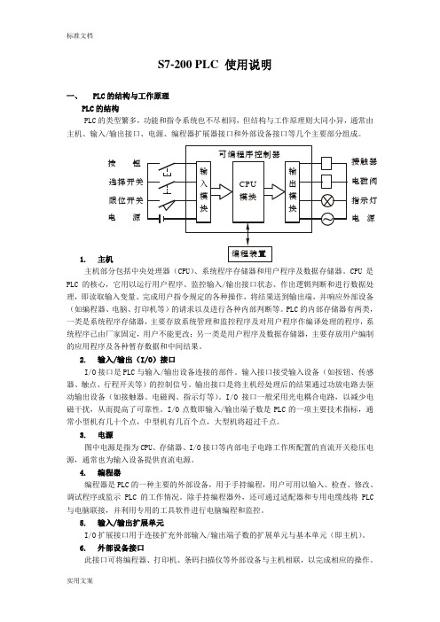
S7-200 PLC 使用说明一、 PLC 的结构与工作原理PLC 的结构PLC 的类型繁多,功能和指令系统也不尽相同,但结构与工作原理则大同小异,通常由主机、输入/输出接口、电源、编程器扩展器接口和外部设备接口等几个主要部分组成。
1. 主机主机部分包括中央处理器(CPU )、系统程序存储器和用户程序及数据存储器。
CPU 是PLC 的核心,它用以运行用户程序、监控输入/输出接口状态、作出逻辑判断和进行数据处理,即读取输入变量、完成用户指令规定的各种操作,将结果送到输出端,并响应外部设备(如编程器、电脑、打印机等)的请求以及进行各种内部判断等。
PLC 的内部存储器有两类,一类是系统程序存储器,主要存放系统管理和监控程序及对用户程序作编译处理的程序,系统程序已由厂家固定,用户不能更改;另一类是用户程序及数据存储器,主要存放用户编制的应用程序及各种暂存数据和中间结果。
2. 输入/输出(I/O )接口I/O 接口是PLC 与输入/输出设备连接的部件。
输入接口接受输入设备(如按钮、传感器、触点、行程开关等)的控制信号。
输出接口是将主机经处理后的结果通过功放电路去驱动输出设备(如接触器、电磁阀、指示灯等)。
I/O 接口一般采用光电耦合电路,以减少电磁干扰,从而提高了可靠性。
I/O 点数即输入/输出端子数是PLC 的一项主要技术指标,通常小型机有几十个点,中型机有几百个点,大型机将超过千点。
3. 电源图中电源是指为CPU 、存储器、I/O 接口等内部电子电路工作所配置的直流开关稳压电源,通常也为输入设备提供直流电源。
4. 编程器编程器是PLC 的一种主要的外部设备,用于手持编程,用户可用以输入、检查、修改、调试程序或监示PLC 的工作情况。
除手持编程器外,还可通过适配器和专用电缆线将PLC 与电脑联接,并利用专用的工具软件进行电脑编程和监控。
5. 输入/输出扩展单元I/O 扩展接口用于连接扩充外部输入/输出端子数的扩展单元与基本单元(即主机)。
Siemens S7-1200 PLC 安装指南说明书
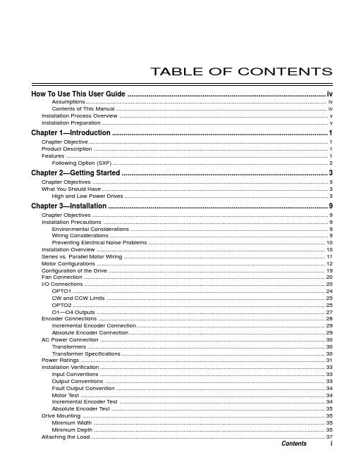
T ABLE OF CONTENTS How To Use This User Guide (iv)Assumptions (iv)Contents of This Manual (iv)Installation Process Overview (v)Installation Preparation (v)Chapter 1—Introduction (1)Chapter Objective (1)Product Description (1)Features (1)Following Option (SXF) (2)Chapter 2—Getting Started (3)Chapter Objectives (3)What You Should Have (3)High and Low Power Drives (3)Chapter 3—Installation (9)Chapter Objectives (9)Installation Precautions (9)Environmental Considerations (9)Wiring Considerations (9)Preventing Electrical Noise Problems (10)Installation Overview (10)Series vs. Parallel Motor Wiring (11)Motor Configurations (12)Configuration of the Drive (19)Fan Connection (20)I/O Connections (20)OPTO1 (24)CW and CCW Limits (25)OPTO2 (25)O1—O4 Outputs (27)Encoder Connections (28)Incremental Encoder Connection (29)Absolute Encoder Connection (29)AC Power Connection (30)Transformers (30)Transformer Specifications (30)Power Ratings (31)Installation Verification (33)Input Conventions (33)Output Conventions (33)Fault Output Convention (34)Motor Test (34)Incremental Encoder Test (34)Absolute Encoder Test (35)Drive Mounting (35)Minimum Width (35)Minimum Depth (35)Attaching the Load (37)Contents iCouplings (37)Tuning (38)Resonance (38)Mid-Range Instability (38)Tuning Procedures (38)Motor Waveforms (40)Anti-Resonance (40)Chapter 4—Application Design (41)Chapter Objectives (41)Motion Profile Application Considerations (41)Preset Mode Moves (42)Incremental Mode Preset Moves (42)Absolute Mode Preset Moves (42)Continuous Mode Moves (43)Closed Loop Operation (44)Setting Encoder Resolution (45)Encoder Step Mode (45)Motion Programs and Sequences (56)Sequence Commands (56)Creating and Executing Sequences (58)Subroutines (59)Sequence Debugging Tools (63)High-Level Programming Tools (67)Complex Branching and Looping (70)Conditionals (71)Error Flag (75)Branching Using Variables and Boolean Logic (76)Motion Profiling Mode—On-the-Fly Changes (77)Interfacing to the SX (81)Programmable Inputs and Outputs (81)PLC Operation (94)Rotary vs. Linear Indexers (97)Chapter 5—SXF Follower (99)Chapter Objectives (99)What is Following? (99)Types of Following (100)Velocity Following (100)Position and Velocity Following (103)Recede and Advance While Following (115)Synchronization (132)Other Following Features (135)Following Equation and Command Summary (137)Chapter 6—Hardware Reference (143)Chapter Objectives (143)Environmental Specifications (143)Drive Electrical Specifications (143)I/O Electrical Specifications (144)Motor Electrical Specifications (147)Operational Specifications (147)Motor Current & Torque (148)Drive Dimensions (149)Motor Dimensions (150)DIP Switch Summary (152)Non-Compumotor—Drive/Motor Connection (155)Wiring Configurations.............................................................................................................................155, 156 Terminal Connections. (157)Non-Compumotor Motors—Setting Motor Current (158)Motor Performance Specifications (158)ii SX/SXF Indexer/Driver User GuideChapter 7—Maintenance & Troubleshooting (161)Chapter Objectives (161)Maintenance (161)Battery Maintenance (161)Drive Maintenance (161)Motor Maintenance (162)Common Problems and Solutions (163)Software Debugging Tips (165)Returning the System (167)Appendices (169)Command Listing (169)SX Example Programs (171)Appendix C—LVD Installation Instructions (175)Complying with the Low Voltage Directive (LVD) (175)Additional Installation Procedures for LVD Compliance (175)Table of Graphic Symbols and Warnings (177)Index (179)Contents iiiHow To Use This User GuideThis user guide is designed to help you install, develop, and maintain your system. Each chapterbegins with a list of specific objectives that should be met after you have read the chapter. Thissection is intended to help you find and use the information in this user guide. AssumptionsThis user guide assumes that you have the skills or fundamental understanding of the followinginformation.t Basic electronics concepts (voltage, switches, current, etc.)t Basic motion control concepts (torque, velocity, distance, force, etc.)Contents of This ManualThis user guide contains the following information.Chapter 1:IntroductionThis chapter provides a description of the product and a brief account of its specific features.Chapter 2:Getting StartedThis chapter contains a detailed list of items you should have received with your SX shipment. Itwill help you to become familiar with the system and ensure that each component functions properly.Chapter 3:InstallationThis chapter provides instructions for you to properly mount the system and make all electricalconnections. Upon completion of this chapter, your system should be completely installed and readyto perform basic operations. Tuning considerations and procedures are also provided.Chapter 4:Application DesignThis chapter will help you customize the system to meet your application’s needs. Importantapplication considerations are discussed. Sample applications are provided.Chapter 5:SXF FollowerThis chapter explains the SXF Following function and the SXF’s capability to support absolute andincremental encoders.Chapter 6:Hardware ReferenceThis chapter contains information on system specifications (electrical, dimensions, and perfor-mance). It may be used as a quick-reference tool for proper switch settings and connections.Chapter 7:TroubleshootingThis chapter contains information on identifying and resolving system problems.iv SX/SXF Indexer/Driver User GuideInstallation Process OverviewTo ensure trouble-free operation, pay special attention to the environment in which the SX equip-ment will operate, the layout and mounting, and the wiring and grounding practices used. Theserecommendations are intended to help you easily and safely integrate SX equipment into yourmanufacturing facility. Industrial environments often contain conditions that may adversely affectsolid-state equipment. Electrical noise or atmospheric contamination, may also affect the SXSystem.Developing Your ApplicationBefore you attempt to develop and implement your application, there are several issues that youshould consider and address.Recognize and clarify the requirements of your application. Clearly define what you expect the system todo.Assess your resources and limitations. This will help you find the most efficient and effective means ofdeveloping and implementing your application (hardware and software).Follow the guidelines and instructions outlined in this user guide. Do not skip any steps or procedures.Proper installation and implementation can only be ensured if all procedures are completed in the propersequence.Installation PreparationBefore you attempt to install this product, you should complete the following steps:Review this entire user guide. Become familiar with the user guide’s contents so that you can quickly findthe information you need.Develop a basic understanding of all system components, their functions, and interrelationships.Complete the basic system configuration and wiring instructions (in a simulated environment, not apermanent installation) provided in Chapter 2, Getting Started.Perform as many basic functions as you can with the preliminary configuration. You can only perform thistask if you have reviewed the entire user guide. You should try to simulate the task(s) that you expect toperform when you permanently install your application (however, do not attach a load at this time). Thiswill give you a realistic preview of what to expect from the complete configuration.After you have tested all of the system’s functions and used or become familiar with tll of the system’sfeatures, carefully read Chapter 3, Installation.After you have read Chapter 3 and clearly understand what must be done to properly install the system,you should begin the installation process. Do not deviate from the sequence or installation methodsprovided.Before you begin to customize your system, check all of the systems functions and features to ensure thatyou have completed the installation process correctly.The successful completion of these steps will prevent subsequent performance problems and allowyou to isolate and resolve any potential system difficulties before they affect your system’soperation.ConventionsTo help you understand and use this user guide effectively, the conventions used throughout this userguide are explained in this section.CommandsAll commands that you are instructed to enter are shown in capital letters. The symbol >, is the SXcommand prompt. The command is displayed in boldface. A delimiter (space or carriage return) isrequired after each command. A description is provided next to each command example.Command Description>MR Sets motor resolution to 25,000 steps/revThe system ignores command syntax that is not within the valid range for a specific command. A ?prompt will be returned by the drive when the last command entered was not understood, or aparameter limit was exceeded.Contents vMotorsS Series and SX Series motors are one in the same (interchangeable terms).Warnings & CautionsWarning and caution notes alert you to possible dangers that may occur if you do not follow instruc-tions correctly. Situations that may cause bodily injury are present as warnings. Situations that maycause system damage are presented as cautions. These notes will appear in bold face and the wordwarning or caution will be centered and in all capital letters. Refer to the examples shown below:WARNINGDo not touch the motor immediately after it has been in use for an extended period of time. The motormay be hot.CAUTIONSystem damage will occur if you power up the system improperly.Related Publicationst Current Parker Compumotor Motion Control Catalogt SX Indexer/Drive Software Reference Guidevi SX/SXF Indexer/Driver User Guide。
西门子PLC操作手册(24个点)

1、先将PLC的电源线插进PLC侧面的电源孔中,再将另一端插到220V电源插板。
2、将PLC的电源开关拨到关状态,严格按图四接线,注意12V电源的正负不要短接,电路不要短路,否则会损坏PLC触点。
3、将PLC的电源开关拨到开状态,并且必须将PLC串口置于ON状态,然后通过计算机或编程器将程序下载到PLC中,下载后,再将PLC的电源开关拨到关状态。
用PLC构成水塔水位自动控制系统
二、实验器材
1、亚龙PLC主机单元一台
2、亚龙PLC水塔水位自动控制单元一台
3、计算机或编程器一台
4、电子连线若干条
5、PLC串口通讯线一条
三、实验原理
1、工作原理如图七所示:
2、水塔水位的工作方式:
当水池液面低于下限水位(S4为ON表示),电磁阀Y打开注水,S4为OFF,表示水位高于下限水位。当水池液面高于上限水位(S3为ON表示),电磁阀Y关闭。
5、将PLC电源开关拨到开状态。
6、按下列步骤进行实验操作:
1)起动电机起停开关,观察电机如何运行。
2)停止电机起停开关,观察电机如何停止。
3)起动报警器开关,观察报警如何运行。
五.思考题
1.如何使电机能延时逐一停止。
2.如何改变报警指示灯的延时长短。
电机起停及报警器控制接线图
图六
实验七
一、实验目的
4、接通1.4(1.2、1.3、1.5不接通),否则无法正确运行演示程序。
5、将PLC电源开关拨到开状态。
6、实验操作过程:
(1)将启动S1先拨上再拨下,观察交通灯的变化。
(2)拨上屏蔽开关S3,观察灯的变化,拨下S3,观察灯的变化。
(3)拨上停止开关S2,观察灯的变化,拨下S2,观察灯的变化。
西门子PLC-SIM使用说明
计算机仿真技术把现代仿真技术与计算机发展结合起来,通过建立系统的数学模型,以计算机为工具,以数值计算为手段,对存在的或设想中的系统进行实验研究。
随着计算机技术的高速发展,仿真技术在自动控制、电气传动、机械制造等工程技术领域也得到了广泛应用。
与传统的经验方法相比,计算机仿真的优点是:(1) 能提供整个计算机域内所有有关变量完整详尽的数据;(2) 可预测某特定工艺的变化过程和最终结果,使人们对过程变化规律有深入的了解;(3) 在测量方法有困难情况下是唯一的研究方法。
此外,数字仿真还具有高效率、高精度等优点。
大型企业每年都需要对电气控制人员进行技术培训,每次培训都需要大量的准备工作,购买大量各种不同类型PLC、变频器、接触器、电缆等。
如果采用传统的经验方法:购买大量的控制器件,特别PLC、变频器等器件昂贵,很容易造成浪费;此外需要专门的培训地点。
所以,如果对控制人员进行技术培训能够采用计算机仿真技术,能极大地降低成本。
S7-PLCSIM Simulating Modules由西门子公司推出,可以替代西门子硬件PLC 的仿真软件,当培训人员设计好控制程序后,无须PLC硬件支持,可以直接调用仿真软件来验证。
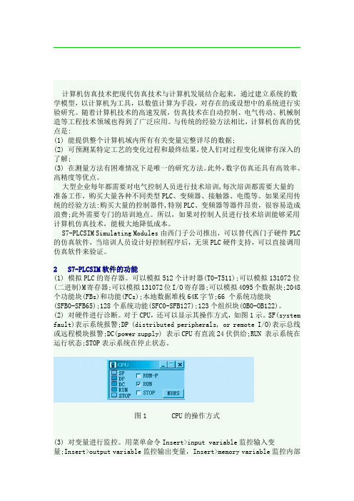
2 S7-PLCSIM软件的功能(1) 模拟PLC的寄存器。
可以模拟512个计时器(T0-T511);可以模拟131072位(二进制)M寄存器;可以模拟131072位I/O寄存器;可以模拟4095个数据块;2048个功能块(FBs)和功能(FCs);本地数据堆栈64K字节;66 个系统功能块(SFB0-SFB65);128个系统功能(SFC0-SFB127);123个组织块(OB0-OB122)。
(2) 对硬件进行诊断。
对于CPU,还可以显示其操作方式,如图1示。
SF(system fault)表示系统报警;DP (distributed peripherals, or remote I/O)表示总线或远程模块报警;DC(power supply) 表示CPU有直流24伏供给;RUN 表示系统在运行状态;STOP表示系统在停止状态。
S7-PLCSIM使用说明书(中文板)

SAVE PLC AS 另存当前PLC
OPEN LAYOUT 打开PLC规划(即你建立的I、O、T、C等等窗口,不包括CPU)
CLOSE LAYOUT 关闭PLC规划
SAVE LAYOUT 保存PLC规划
Clear/rest 清除程序,除通讯外全部复位
MPI address 设定MPI通讯地址
insert 插入(和培置硬件模块一样):
input variadle 插入输入端口,可为I、Ib、IW、ID、PI、PIb、PID、PIW 的 监视窗口
PLCSIM)
1。打开SIMATIC管理器
2。建立项目
3。启动PLCSIM
4。单击站,双击硬件配置浏览器,配置硬件。并向PLCSIM下载硬件配置.
5。根据硬件配置,再PLCSIM中建立本项目PLC的输入输出模块。
6。单击SIMATIC管理器,编辑符号表和源程序块。
help
cantents 内容
zhtroduction 入门
getting 快速应用
using Hele 利用帮助
about 版本
conunter 插入计数器,同上
geheric 插入普通变量
vertical bit 插入垂直变量
Execute: 可执行的菜单
key swith position 状态方式开关键
run-p 可上载、下载,监视得运行状态
run 监视运行状态,不能上载、下载,当你修改了程序无法下载到仿真PLC里去时,可能仿真PLC在此状态下。
stop 停滞状态,可上载、下载
PLC:
Power on PLC电源开
PCS7软件模拟PLC—SIM培训(高端培训)
S7-PLCSIM软件入门
•使用程序编辑器监视状态 要在程序的梯形图视图中观察程序的执行,按照下述步骤: 1、访问SIMATIC管理器窗口; 2、选择在线的FC1并双击,和使用菜单命令EditOpen Object打开程序; 3、选择菜单命令DebugMonitor,将在梯形网络中使能程序执行的动画。 现在可以在梯形网络中观察输入、输出、存储位和定时器元件的电流流动了。
S7-PLCSIM提供了一个简单的界面用于监视和修改程序中不同的参数 (例如打开和关闭输入端)。当你在模拟的CPU上运行程序时也可以使用STEP 7 软件不同应用程序。这也让你可以使用如VAT(变量表)之类的工具去监视和修 改变量。
•S7-PLCSIM的特性 •模拟PLC的局限性 •模拟PLC和真实PLC之间的区别
工程师培训资料
• 标题:PCS7软件模拟PLC—SIM培训(高端培训) • 培训人:xx
PLCSIM V5.3介绍
S7-PLCSIM是用于STEP 7的可选项软件包。该软件允许你在个人电脑上用一 台模拟的PLC对所编程序进行运行和测试。由于模拟完全存在于STEP 7软件上, 因此你无需连接到任何S7硬件(如CPU或I/O模块)。用模拟的S7系列CPU,你 可以对用于S7-300和S7-400系列CPU的程序进行测试和监控。
- 1、下载文档前请自行甄别文档内容的完整性,平台不提供额外的编辑、内容补充、找答案等附加服务。
- 2、"仅部分预览"的文档,不可在线预览部分如存在完整性等问题,可反馈申请退款(可完整预览的文档不适用该条件!)。
- 3、如文档侵犯您的权益,请联系客服反馈,我们会尽快为您处理(人工客服工作时间:9:00-18:30)。
S7-PLCSIM使用入门Getting Started of S7-PLCSIM摘要本文档主要用于讨论以下相关问题: S7-PLCSIM工具软件的基本信息S7-PLCSIM工具软件的简单使用 关键词Step7;S7-PLCSIMKey WordsStep7;S7-PLCSIM目录S7-PLCSIM使用入门 (1)1.前言 (4)2.软件的基本信息 (4)2.1.S7-PLCSIM简介 (4)2.2.S7-PLCSIM与真实PLC的差别: (4)2.2.1.S7-PLCSIM安装与使用: (5)2.3.S7-PLCSIM软件兼容性 (6)3.S7-PLCSIM的使用 (6)3.1.S7-PLCSIM特性 (6)3.2.S7-PLCSIM调用 (7)3.3.S7-PLCSIM简单示例 (7)3.3.1.S7-PLCSIM界面: (7)3.3.2.S7-PLCSIM菜单 (8)3.4.S7-PLCSIM的常见问题 (10)3.4.1.问题:S7-PLCSIM与在线连接的优先级 (10)3.4.2.问题:S7-PLCSIM与WinLC的区别 (11)3.4.3.问题:无法调用OB40 (11)3.4.4.问题:S7-PLCSIM仿真通信程序 (11)3.4.5.问题:S7-PLCSIM是否可以仿真定时器或定时中断功能 (11)3.4.6.问题:项目下载后,S7-PLCSIM 的SF点亮 (11)4.附录-推荐网址 (12)4.1.西门子自动化与驱动产品的在线技术支持 (12)重要提示:本文为技术交流文档,不能作为订货、选型等重要事宜的唯一依据,建议您参考Siemens的标准产品样本和技术手册进行产品的选型和订货。
1. 前言本章节可以作为 S7-PLCSIM软件的使用参考资料,希望读者通过对本章的阅读,能够更快更好地学习S7-PLCSIM软件的使用。
西门子提供了S7-PLCSIM软件的详尽手册,在安装S7-PLCSIM 软件包后,通过点击Windows菜单 开始->Simatic->Documentation->English可以阅读到名称为“S7-PLCSIM - Testing Your S7-CPU Programs - manual”的PDF手册。
一切关于S7-PLCSIM使用的问题请以此手册为准。
相关手册地址连接:S7-300和S7- 400的梯形图 (LAD) 编程/CN/view/zh/18654395S7-300 和S7-400 的语句表 (STL) 编程/CN/view/zh/18653496S7-300 和S7-400 的功能块图 (FBD) 编程/CN/view/zh/18652644使用STEP 7 V5.3 编程/CN/view/zh/18652056S7-PLCSIM for SIMATIC S7/CN/view/zh/11390712. 软件的基本信息2.1. S7-PLCSIM简介使用S7-PLCSIM具有以下优点:在PG/PC上进行不依赖于硬件的S7程序测试在程序开发早期消除错误降低开发成本,加速开发进程,提高程序质量适用于 LAD, FBD, STL, S7-GRAPH, S7-HiGraph,S7-SCL, CFC, S7-PDIAG, WinCC (本地安装)2.2. S7-PLCSIM与真实PLC的差别:S7-PLCSIM 并不能完全代替真实的PLC, 它与真实的硬件PLC有着如下的差别:当对S7-PLCSIM进行“STOP”操作后,程序再开始时,从中断处开始执行当对S7-PLCSIM进行“STOP”操作时,不影响输出状态当在子窗口修改变量时,其修改立刻有效,而不会等到下个周期你可以手动修改或复位定时器的值可以实现单周期操作模式你可以触发中断OB块对过程映像区的修改立刻生效不支持所有的诊断信息,例如EEPROM错误不支持多CPU模式S7-PLCSIM 提供高档 CPU 才拥有的系统资源(例如定时器范围为 T0-T2047, M 范围为16KB), 所以当使用S7-PLCSIM 模拟通过的程序(假设使用了定时器 T2000),可能会无法下载到低档CPU上运行(例如CPU315-2AG10-0AB0定时器范围为T0-T255,)。
不支持FM功能模块不支持通信功能S7-PLCSIM类似于400有4个累加器,所以不同于仅有2个累加器的300CPU对于调用以下块,S7-PLCSIM 执行空操作:•SFB12, SFB13, SFB14, SFB15, SFB16, SFB19, SFB20, SFB21, SFB22 , SFB23, SFB41, SFB42, SFB43, SFB44, SFB46, SFB47, SFB48, SFB49, SFB60,SFB61,SFB62, SFB63, SFB64, and SFB65•SFC7, SFC11, SFC12, SFC25, SFC35, SFC36, SFC37, SFC38, SFC48, SFC60, SFC61, SFC62, SFC65, SFC66, SFC67, SFC68, SFC69, SFC72, SFC73,SFC74,SFC81, SFC82, SFC83, SFC84, SFC87, SFC102, SFC103, SFC105,SFC106,SFC107, SFC108, SFC126 and SFC127•OB55, OB56,OB57, OB61, OB62, OB63,OB64, OB81, OB84, OB87, OB88 and OB90 关于S7-PLCSIM与真实PLC 的详细差异,请参考以下地址链接:/CN/view/zh/11610958特别提示:此问题是每个S7-PLCSIM使用者都会关心的问题,使用者务必要牢记以上的差别。
2.2.1. S7-PLCSIM安装与使用:STEP7标准版并不包括S7-PLCSIM软件包及授权,需单独购买,STEP7 Professional 版包括了S7-PLCSIIM的软件包及授权,安装即可。
在菜单Options中,可以激活S7-PLCSIM,此时再进行上传/下载/监控等操作就是针对S7-PLCSIM了,而不会对真实PLC进行操作(不论PLC是否联机)。
图2-1S7-PLCSIM 调用2.3. S7-PLCSIM软件兼容性不同S7-PLCSIM 软件版本与STEP7及操作系统之间的兼容性:图中的 X 表示兼容,- 表示不兼容图2-2S7-PLCSIM 软件兼容性3. S7-PLCSIM的使用3.1. S7-PLCSIM特性S7-PLCSIM 可以模拟一个S7控制器,并且具备以下资源:内存区域描述定时器 T0-T2047M 存储器 131,072 BIT(16K BYTE)I/O地址范围 131,072 BIT(16K BYTE)过程映像区(可设置,最大131,072 BIT(16K BYTE)每个扫描周期更新)预设值:8192 BIT(1024 BYTE)最大64K BYTE本地数据区(可设置)预设值:32K BYTE)逻辑块和数据块2048 FB/FC, 4095 DB除SFB12, SFB13, SFB14, SFB15, SFB16, SFB19, SFB20, SFB21, SFB22 ,SFB23, SFB41, SFB42, SFB43, SFB44, SFB46, SFB47, SFB48, SFB49,SFB60,SFB61, SFB62, SFB63, SFB64, SFB65 以外的SFBSFB除SFC7, SFC11, SFC12, SFC25, SFC35, SFC36, SFC37, SFC38, SFC48,SFC60, SFC61, SFC62, SFC65, SFC66, SFC67, SFC68, SFC69, SFC72,SFC73,SFC74, SFC81, SFC82, SFC83, SFC84, SFC87, SFC102, SFC103,SFC105,SFC106, SFC107, SFC108, SFC126, SFC127 以外的SFCSFCOB 除OB55, OB56,OB57, OB61, OB62, OB63,OB64, OB81, OB84, OB87, OB88 and OB90以外的OB另外,S7-PLCSIM 还具备以下特性:•可以插入视图来访问:PLC的输入/ 输出/中间寄存器/定时器/计数器/数据块,支持符号地址访问方式•可以使定时器自动运行或手动控制它们,可以分别或统一复位定时器•可以更改CPU操作模式 (STOP, RUN, RUN-P)。
并且S7-PLCSIM 提供了暂停模式,用户可停止程序的执行,而不影响仿真CPU中的状态•S7-PLCSIM 提供了单周期扫描模式,可以方便调试•可以使用中断 OB 来测试程序逻辑•可以记录一系列事件(操作输入/输出/M存储器/定时器),并且可以回放记录的事件,可以用于自动程序测试•可以使用所有的 STEP 7 工具来监视和调试S7-PLCSIM所仿真的PLC(而不需要实际的硬件) 3.2. S7-PLCSIM调用可以通过STEP7菜单Options-> Simulate Modules,激活S7-PLCSIM;或者通过点击工具栏中的图标,来激活S7-PLCSIM。
3.3. S7-PLCSIM简单示例3.3.1. S7-PLCSIM界面:下图为S7-PLCSIM工作界面,图3-1: S7-PLCSIM 视图3.3.2. S7-PLCSIM菜单1.File菜单:用户可以通过S7-PLCSIM菜单File > Save PLC As, 将当前模拟的PLC存储为一个文件,下次使用时可以通过File > Open PLC,直接打开此文件,而不需要下载过程,方便调试。
对于S7-PLCSIM V5.4版本,可以在此设置多种下载方式,例如,MPI, DP, Ethernet。
2.View菜单:用户可以通过View > Accumulators/Block Registers/Stacks来查看PLC内部的累加器/地址寄存器/状态字/堆栈资源3.Insert菜单:用户可以通过Insert >Input Variable插入变量(输入/ 输出/中间寄存器/定时器/计数器/数据块)方式来模拟各种工况。
4.PLC菜单:用户可以通过PLC 菜单模拟真实PLC的上电/断电,内存复位操作,以及修改PLC的MPI地址(S7-PLCSIM V5.4版本以下)。