华硕 K8N4-E 主板使用手册
ASUS FrontLinker 用户手册说明书

FrontLinker™User GuideContents Welcome (2)Package.contents (2)FrontLinker™ specifications summary (3)Device.overview (4)Device.installation (5)USB standby power (7)Features (8)Magic cables usage (8)Multimedia card reader (9)Front.panel.connectors (9)FrontLinker™ DH panel board layout (10)WelcomeThank you for choosing the ASUS FrontLinker™!The ASUS FrontLinker™ is your convenient access to some of the most useful computer ports. With the latest features in digital technology developed by ASUS, the ASUS FrontLinker™ is sure to keep you ahead in the world of digital computing!Package contentsCheck the following items in your ASUS FrontLinker™ package. Contact your retailer if any item is damaged or missing.ASUS FrontLinker™User guideMP3-In, USB 2.0, IEEE 1394a, Serial ATA, and Front Panel Audio cables . (By default, these cables are plugged into the ASUS FrontLinker™)FrontLinker™.specifications summaryDimensions 148.5.x.42.8.x.121.1.mm5.25-inch (CD-ROM Size Front Panel)Front panel I/OB.2.01 x IEEE 1394a (6-pin)1 x External Serial ATA (E-SATA) port1 x Karaoke 6.3 mm mic port Magic Cables1.x.MP3-In.cable 1.x.iPod ®.Dock.cable1.x.miniUSB.2.0.cable Card reader*Compact.Flash SmartMediaSecure Digital (SD/mini SD)MultiMedia Card Memory StickMemory Stick Pro Special featuresMagic Charger™: E nables users to charge portable devices viaUSB 2.0 cable without turning on the PC*Magic Stereo™ (MP3-In cable): E nables users to playbackmusic via PC stereo speakers without turning on the PCSupported motherboards Supports all ASUS motherboards**FrontLinker™ functions may vary depending on the available connectors.on.the.motherboard.•.Magic Charger™ feature supports all motherboards with USB.connectors.• Magic Stereo™ feature supports all ASUS Digital Home motherboards (except P5LD2-VM DH and N4L-VM DH).* For some portable devices, you may need to turn on the PC to charge the battery.** For some storage cards, you may need to purchase a separate adapter. *** Specifications are subject to change without notice.Device overviewMagic CablesFront panel* The card reader LED blinks when reading/writing a storage card.** You may put the Magic Cables through the cable passage while the cable access door is closed.Device installationTo install the ASUS FrontLinker™:1. Remove the cover of an empty 5.25”drive bay.We suggest installing theFrontLinker™ into the upper drive bay of the PC, not under the optical drives.2. Plug the 4-pin ATX power cable intothe ATX power connector on the FrontLinker™.3. Insert the FrontLinker™ to the drive bay.Let.all.the.cables.pass.inside.the.PC.case. Carefully push the FrontLinker™ until its screw holes align with the holes on the drive bay.4. Secure the FrontLinker™ with screws onboth sides of the drive bay.We suggest that you place your portable devices on top of the chassis whileconnecting.to.the.FrontLinker™.5. Two Front Panel Audio cables are connected to the FrontLinker™. The shorter oneshould be connected with the audio cable from the chassis. For the connection of another Front Panel Audio cable, refer to step 6.Description.Front Panel Audio cable.(black.connector) (male).or.Connect the shorter cable, with male connector, to the audio cable from the chassis .*.6* You may need to define which type of the audio standard is supported bythe chassis (refer to the chassis manual). Then refer to the below figure toconnect the audio cable from the chassis to the FrontLinker™.Legacy AC ‘97 audiopin definitionHD Audio-compliantpin definition6. By default, one end of each cable listed below is already connected to the FrontLinker™. Plug the other end of these cables to the corresponding connectors on.the.motherboard.FrontLinker™ Front Panel Audio connectorUSB standby powerIf your motherboard does not have auto-switch function (refer to the motherboard manual), you may need to set up jumpers. .You may find a number of jumpers labelled “USBPW” on your motherboard. The USBPW12 and USBPW34 jumpers are for the USB ports on the rear panel. The USBPW56 and USBPW78 jumpers are for the internal USB connnectors that you can connect to additional USB ports. You only need to set up USBPW56 and USBPW78 for using the FrontLinker™. If the jumper of the USB is not set to +5VSB position, refer to your motherboard manual to set the jumper to +5VSB position. Here we take ASUS P5VD2-MX motherboard an example:(Default)USBPW56USBPW78USBPW12(Default)• The total current consumed must NOT exceed the power supply capability (+5VSB) whether the PC is turned on or off. Overloading the current consumed when the PC is turned off may result in startup failure.•We suggest charging no more than two devices at the same time when the PC is turned off.ex:•Make sure the USB connector on the motherboard is set to +5VSB. You may need to set up jumpers if your motherboard does not have auto-switch function (refer to the motherboard manual). For detailed information about jumper settings, refer to the section “USB standby power”.•We suggest connecting the SATA cable to the E-SATA .connector.on.the.motherboard (not any SATA connector); otherwise, the transfer rate may be decreased. Refer to the motherboard manual for the location of E-SATA connector.• Make sure that the cables are firmly connected on both ends.•When the PC is turned on, the power supply comes from ATX power cable; when the PC is turned off, the power supply comes from +5VSB on the USB.connector.7. The blue LED indicator lights up when the power cable from the power outlet isconnected to the PC, the USB cable is correctly connected to the motherboard, and the USB connector on the motherboard is set to +5VSB. For the location of the blue LED indicator, refer to the “FrontLinker™ DH panel board layout” on page 10.Don’t forget to connect the power cable from the power outlet to the PC.FeaturesMagic Charger™ASUS FrontLinker™ is designed with Magic Cables that allow you tocharge your portable devices such as mobile phones, PDAs, and MP3players with ease. You can charge your devices without turning on thePC!Magic Stereo™ASUS FrontLinker™ allows you to playback music from devices connected to MP3-In cable via PC stereo speakers. Furthermore, you can enjoylistening to your music when the PC is turned off. To do so, simply plug theMagic cables into the corresponding ports on your portable device and turn on the speaker. Then you can play your portable device as usual.Magic cables usageThe length of the Magic Cables is retractable. You can set the cable length you want by pulling out the cable to the desired distance. Pull out the cables to the end and release slowly to retrieve the cables.device or download/upload files between the PC and your portable device. Simply connect the cable to the miniUSB port of your portable device. When charging the battery, you may turn off the PC. For file transfers, both PC and your portable device should be turned on.Magic Cable for Apple® iPod®The Magic Cable for iPod®® battery, and download/upload files between the PC and iPod®. Simply plug the cable into the corresponding port on your iPod® to start using the function. For file transfers and battery charging, both PC and your iPod® should be turned on.your portable devices by using the PC stereo as the output. Simply plug thecable into the audio-out port on your portable device to start using the function.9Multimedia card readerWith the card reader placed on the front panel of the computer case, users are able to read and save data easily. You no longer need to waste desk space for external.card.readers.Follow the information below to insert cards to the specified card slots. Look at the label beside each card slot for reference.CF card slot : Supports Compact Flash (CF) card.SM card slot : Supports Smart Media card (SM).MS card slot : Supports Memory Stick and all Memory Stick Pro series.SD/MMC card slot : Supports Secure Digital (SD/mini SD) and Multi-mediacard.Front panel connectorsFront panel IEEE 1 9 a port (1 9 )The front-loaded IEEE 1394a port is more convenient for users, allowing you to connect to video devices, storage peripherals, or portable devices in 1394a interface easily. Make sure IEEE 1394a cable is connected to the IE1394a connector on your motherboard before using the function.External SATA port (E-SATA)The front-accessed E-SATA port, supporting Serial ATA 1.5 Gb/s and Serial ATA II 3.0 Gb/s devices, enables users to connect to an external SATA box with ease. Ensure that SATA cable is connected to the external SATA connector on your motherboard before using this function.The distance between the E-SATA port and your SATA device should notexceed.1.5.m.•Hold the cable header and pull out the cable to the end, then release SLOWLY to retrieve the Magic Cables. Do not release the cables quickly, doing.so.might.damage.the.FrontLinker™.• We suggest leaving the cable access door open while pulling/releasing the cables to avoid the risk of a cable jam.•The total current consumed must NOT exceed the power supply capability (+5VSB) whether the PC is turned on or off. We suggest charging no more than two devices at the same time when the PC is turned off.•Use this product according to instructions in the user guide. Productwarranty or service does not cover damage resulting from incorrect usage.10with ease. Ensure the USB 2.0 cable is connected to USB connector on your motherboard before using the function. You can charge your device at anytime whether the PC is turned on or off.Karaoke 6. mm microphone portThe front-loaded karaoke microphone port is convenient for sound input and sound recordings. Ensure the Front Panel Audio cable is connected to the Front Panel Audio connector on your motherboard before using the function.The karaoke 6.3 mm microphone port on the FrontLinker™ and the microphoneport on the chassis share the same Front Panel Audio connector on themotherboard. Using the two ports simultaneously may result in overdubbing orother unexpected effects. Therefore, we strongly suggest not plugging in thetwo.ports.at.the.same.time.FrontLinker™ DH panel board layout161. E-SATA connector2. IEEE 1394a connector3. ATX Power connectorB.2.0.connector5. Standby Power LED blue indicator6. Front Panel Audio connector(connected to chassis)9101117. Front Panel Audio connector(connected to motherboard)8..MP3-In.connector9. Magic Cable for miniUSB connector10. Magic Cable for iPod®.connector11..Card.reader.connector12. Magic Cable for MP3-In connector。
华硕主板设置图

华硕主板设置图华硕主板设置图2007-07-21 11:28计算机系统安装(最新AMI Bios 设置全程图解)2007年07月04日星期三03:14对于一个热衷于电脑的用户来说,最大的乐趣就是发觉计算机的潜能,了解计算机的一些技术,计算机的Bios设置对于很多初用电脑人的来说很是深奥,甚至一些计算机的老用户还不了解Bios,因为计算机Bios涉及了很多计算机内部硬件和性能差数设置,对于一般不懂电脑的人来说有一定的危险性,加之一般Bios里面都是英文,这个对于英语好的人来说没有问题,但是这毕竟是中国,还有很多人对英语并不是很懂,所以很多人不敢轻易涉足!为了把大家的这些疑惑解决,我利用空闲时间把Bios 的设置用图文解释给大家看看,希望能给一部分人一些帮助!但是因为个人知识有限,所以可能其中有一些遗漏或者不正确的解释,请大家一起来探讨指正!谢谢各位的支持!我找了两种Bios的计算机分别是:华硕的AMI BIOS和升技的AWARD BIOS,这也是目前两种主流的Bios,及算是不同品牌的主板,他们的Bios也是与这两种Bios的功能和设置大同小异,但是一般不同的主板及算是同一品牌的不同型号的主板,他们的Bios又还是有区别的,所以一般不同型号主板的Bios不能通用!先以华硕的AMI Bios为例,介绍一下AMI Bios 的设置:开启计算机或重新启动计算机后,在屏幕显示如下时,按下“Del”键就可以进入Bios的设置界面要注意的是,如果按得太晚,计算机将会启动系统,这时只有重新启动计算机了。
大家可在开机后立刻按住Delete键直到进入Bios。
有些品牌机是按F1进入Bios设置的,这里请大家注意!进入后,你可以用方向键移动光标选择Bios设置界面上的选项,然后按Enter进入子菜单,用ESC键来返回主单,用PAGE UP和PAGE DOWN键或上下( ↑↓ )方向键来选择具体选项回车键确认选择,F10键保留并退出Bios设置。
AMD装机配置大全(3000-15000)

近期装电脑的朋友很多,要配置的也很多。
这里我整理了一些不同价位的AMD 配置。
供大家装机参考。
配置中参阅了一不小心明日帝国的的有些配置。
这里提出感谢也对哈士奇,宝盛提供配置表示感谢!(一)3000入门级64位配置CPU: AMD SP2500+(盒)530 / AMD Sempron 2800+ (64Bit) 640元主板: 映泰TForce 6100 590昂达N61G499磐正EP-8GF6100-M 599/华硕K8N-VM 590元富士康WinFast 6100K8MB-RS 510 (以上5块集成了6200TC显示核心)迪兰恒进AX480A7-F 599七彩虹C.MK8AS-754 Ver1.4 599(这两块整合了ATI X300SE显示核心)内存: 金士顿/三星金条512M DDR400 350硬盘: 西部数据WD800JB(三年保) 410希捷7200.9 80G 2M 410光驱:华硕雪豹光驱120显卡: 集成显示器:AOC 772S 830/AOC 771S799元大宇719BF-3 799LG T711S 850海尔HV-773CK 799金长城G782F 790 (带宽150MHz)长城P4300W+空箱200键鼠:力胜黑豹键鼠套装55点评:AMD Sempron 2500+ (64Bit)1.4G 530元由于有着良好的超频性能,大多用户可以超到300以上的外频,所以深受喜爱AMD用户的喜欢,是一款性能不错的入门级的CPU。
配置为AMD入门级的家庭娱乐方案,适合要求不高的用户,可以满足上网、办公、看DVD碟片、玩一点小游戏。
(补充一:3800左右配置)CPU:AMD SP 2500+(64)530元/AMD SP 2800+(64)640元主板:昂达NF4S 490/映泰K8T890-A7499元七彩虹C.NF4X490/磐正EP-8HEAI 499元捷波K8N8P-C 490磐正8NPAI 590/映泰NF4 4X-A7 580元梅捷SY-A8N4-RL 590富士康NF4K8AB-RS 590显卡:微星阿修罗RX550-TD128E 499/技嘉X600PRO 499元微星/华硕/Inno3D/ 7300GS 490影驰6600重炮手590元/七彩虹镭风X700-GD3 冰封骑士4 599元内存:宇瞻512M DDR400 340金士顿/三星金条512M DDR400 350硬盘:西数WD800JB 410光驱:华硕DVD 200机箱:自选100电源:长城300W 120显示器:飞力浦107H6 920点评:本配置为AMD入门级独立显卡家庭娱乐方案,可以满足普通用户游戏基本要求。
华硕 M2N-E 主板 说明书

用 戶 手 冊C26301.00 版2006 年 7 月發行版權所有·不得翻印 © 2006 華碩電腦本產品的所有部分,包括配件與軟件等,其所有權都歸華碩電腦公司(以下簡稱華碩)所有,未經華碩公司許可,不得任意地仿製、拷貝、謄抄或轉譯。
本用戶手冊沒有任何型式的擔保、立場表達或其它暗示。
若有任何因本用戶手冊或其所提到之產品的所有信息,所引起直接或間接的數據流失、利益損失或事業終止,華碩及其所屬員工恕不為其擔負任何責任。
除此之外,本用戶手冊所提到的產品規格及信息只能參考,內容亦會隨時升級,恕不另行通知。
本用戶手冊的所有部分,包括硬件及軟件,若有任何錯誤,華碩沒有義務為其擔負任何責任。
用戶手冊中所談論到的產品名稱僅做識別之用,而這些名稱可能是屬于其他公司的註冊商標或是版權。
本產品的名稱與版本都會印在主板/顯卡上,版本數字的編碼方式是用三個數字組成,並有一個小數點做間隔,如 1.22、1.24 等...數字越大表示版本越新,而越左邊位數的數字更動表示更動幅度也越大。
主板/顯卡、BIOS 或驅動程序改變,用戶手冊都會隨之升級。
升級的詳細說明請您到華碩的全球信息網瀏覽或是直接與華碩公司聯絡。
目 錄 內 容 (3)安全性須知 (7)電氣方面的安全性 (7)操作方面的安全性 (7)關于這本用戶手冊 ...................................................................................................-8用戶手冊的編排方式 .. (8)哪裡可以找到更多的產品信息 ..................................................................-8提示符號 (9)M2N-E 規格列表 (10)第一章:產 品 介紹1.1 歡迎加入華碩愛好者的行列 .....................................................................1-11.2 產品包裝 ..........................................................................................................1-11.3 特殊功能 ................................................................................................1-21.3.1 產品特寫 ............................................................................................1-21.3.2 華碩 AI Lifestyle 功能 .................................................................1-41.3.3 華碩獨家研發功能 ..........................................................................1-51.3.4 華碩智能型超頻功能 .....................................................................1-6第二章:硬 件 設 備 信 息2.1 主板置入前 ......................................................................................................2-1電力指示燈 ....................................................................................................2-12.2 主板概述 ..........................................................................................................2-22.2.1 主板的擺放方向 ..............................................................................2-22.2.2 螺絲孔位 ............................................................................................2-22.2.3 主板結構圖 ........................................................................................2-32.2.4 主板元件說明 ...................................................................................2-42.3 中央處理器(CPU) ...................................................................................2-62.3.1置入中央處理器 ................................................................................2-62.3.2 置入散熱片與風扇 ..........................................................................2-82.4 系統內存 .......................................................................................................2-112.4.1 概述 -112.4.2 內存設置 .........................................................................................2-112.4.3 置入內存模組 ................................................................................2-152.4.4 取出內存模組 ................................................................................2-152.5 擴充插槽 .......................................................................................................2-162.5.1 置入擴充卡 .....................................................................................2-162.5.2 設置擴充卡 .....................................................................................2-162.5.3 指定中斷要求 ................................................................................2-172.5.4 PCI 擴展卡擴充插槽 ...................................................................2-172.5.5 PCI Express x4 擴展卡擴充插槽與 PCI Express x1 擴展卡擴充插槽 ..................................................................................................2-182.5.6 PCI Express x16 擴展卡擴充插槽 .......................................2-182.6 跳線選擇區 ...................................................................................................2-192.7 元件與外圍設備的連接 ............................................................................2-202.7.1 后側面板連接埠 ...........................................................................2-202.7.2 內部連接埠 .....................................................................................2-21第三章:開 啟 電 源3.1 第一次啟動電腦 .................................................................................................3-13.2 關閉電源 ..........................................................................................................3-23.2.1 使用操作系統關機功能 .................................................................3-23.2.2 使用電源開關之雙重功能 ............................................................3-2第四章:BIOS 程 序 設 置4.1 管理、升級您的 BIOS 程序..........................................................................4-14.1.1 華碩在線升級 ...................................................................................4-14.1.2 製作一張啟動盤 ..............................................................................4-44.1.3 使用華碩EZ Flash 2升級 BIOS 程序 .......................................4-54.1.4 使用 AwardBIOS Flash 程序升級 BIOS .................................4-64.1.5 儲存目前的 BIOS 檔案 .................................................................4-84.1.6 使用 CrashFree BIOS 3 程序恢復 BIOS 程序 .....................4-94.2 BIOS 程序設置 ............................................................................................4-104.2.1 BIOS 程序菜單介紹.....................................................................4-114.2.2 程序功能表列說明 .......................................................................4-114.2.3 操作功能鍵說明 ...........................................................................4-124.2.4 菜單項目 .........................................................................................4-124.2.5 子菜單 ..............................................................................................4-124.2.6 設置值 ..............................................................................................4-124.2.7 設置窗口 .........................................................................................4-134.2.8 在線操作說明 ......................................................................4-134.3 主菜單(Main Menu) ............................................................................4-144.3.1 System Time [XX:XX:XX] .......................................................4-144.3.2 System Date [Day XX/XX/XXXX] .....................................4-144.3.3 Legacy Diskette A [1.44M, 3.5 in.] ....................................4-144.3.5 IDE 設備菜單 .................................................................................4-154.3.6 SATA 設備1-6(SATA 1-6) ....................................................................4-174.3.6 硬盤 SMART 監控項目 .............................................................4-184.3.7 已置入內存 [XXX MB] ..............................................................4-184.3.8 可使用內存 [XXX MB] ..............................................................4-184.4 高級菜單(Advanced menu) .............................................................4-194.4.1 JumperFree 設置(JumperFree Configuration) ..........4-19高級電壓控制Advanced Voltage Control ......................................4-214.4.2 AI NET2 .........................................................................................4-224.4.3 PEG Link Mode............................................................................4-224.4.4 CPU Configuration .....................................................................4-234.4.5 芯片組設置(Chipset) ............................................................4-274.4.6 PCI 即插即用設備(PCI PnP) .............................................4-284.4.7 內置設備設置(OnBoard Devices Configuration) ....4-294.5 電源管理(Power menu) ....................................................................4-324.5.1 ACPI Suspend Type [S1&S3] ................................................4-324.5.2 ACPI APIC Support [Enabled] ...............................................4-324.5.3 高級電源管理設置(APM Configuration) ......................4-334.5.4 Hardware Monitor ......................................................................4-354.6 啟動菜單(Boot menu) ........................................................................4-374.6.1 啟動設備順序(Boot Device Priority) .............................4-374.6.2 可攜式設備(Removable Drives) .......................................4-384.6.3 硬盤(Hard Disk Drives) .......................................................4-384.6.4 CD-ROM 驅動器(CDROM Drives) .................................4-384.6.5 啟動選項設置(Boot Settings Configuration) .............4-394.6.6 Security ...........................................................................................4-404.7 工具菜單(Tools menu) ......................................................................4-424.7.1 ASUS Music Alarm .....................................................................4-424.7.2 ASUS O.C. Profile .......................................................................4-444.7.3 ASUS EZ Flash 2 ........................................................................4-464.8 離開 BIOS 程序(Exit menu) ......................................................4-47第五章:軟件支持5.1 置入操作系統 ......................................................................................................5-15.2 驅動程序及公用程序光碟信息 .................................................................5-15.2.1 運行驅動程序及公用程序光碟 ...................................................5-15.2.2 驅動程序菜單(Drivers menu) ...............................................5-25.2.3 公用程序菜單(Utilities menu) ...............................................5-35.2.4 製作磁盤菜單 ...................................................................................5-45.2.5 Manuals menu .................................................................................5-55.2.6 華碩的聯絡方式 ..............................................................................5-65.2.7 其他信息 ............................................................................................5-65.3 軟件信息 ..........................................................................................................5-85.3.1 AMD 冷卻與靜音功能 ..................................................................5-85.3.2 華碩系統診斷家 II ........................................................................5-105.3.3 華碩音樂鬧鈴功能(ASUS Music Alarm) ......................5-165.3.4 華碩 AI Nap ...................................................................................5-195.3.5 華碩 AI Gear ................................................................................5-205.3.7 SoundMAX® 高傳真音頻設置程序 ......................................5-22Audio Setup Wizard(音頻設置向導) ..........................................5-235.4 RAID 功能設置 ...........................................................................................5-265.4.1 硬盤置入 .........................................................................................5-275.4.2 NVIDIA® MediaShield™ RAID 磁盤數組功能設置 ........5-285.5 創建一張搭載有 RAID 驅動程序的磁盤 ...........................................5-35安全性須知電氣方面的安全性• 為避免可能的電擊造成嚴重損害,在搬動電腦主機之前,請先將電腦電源適配器暫時從電源插槽中拔掉。
华硕 M4N78 SE 说明书

用 戶 手 冊C4424第 1 版2009 年 2 月發行版權所有‧不得翻印 © 2009 華碩電腦本產品的所有部分,包括配件與軟件等,其相關知識產權等歸華碩電腦公司(以下簡稱華碩)或授權華碩使用的相關主體所有,未經權利主體許可,不得任意地仿製、拷貝、摘抄或轉譯。
本用戶手冊沒有任何型式的擔保、立場表達或其它暗示。
若有任何因本用戶手冊或其所提到之產品信息,所引起直接或間接的數據流失、利益損失或事業終止,華碩及其所屬員工恕不為其擔負任何責任。
除此之外,本用戶手冊所提到的產品規格及信息只作參考,內容亦會隨時疏漏或升級,恕不另行通知。
下列因素導致的產品故障或損壞不在免費保修範圍內:A. 因天災(水災、火災、地震、雷擊、颱風等)、遇不可抗拒外力或人為之操作使用不慎造成之損害。
B. 自行拆裝、修理、或將產品送至非華碩認証之維修點進行檢測維修。
C. 用戶擅自或請第三人修改、修復、變更規格及安裝、添加、擴充非本公司原廠銷售、授權或認可之配件所引起之故障與損壞。
D. 因用戶自行安裝軟件及設定不當所造成之使用問題及故障。
E. 計算機病毒所造成之問題及故障。
F. 本公司保修識別標籤撕毀或無法辨認,涂改保修服務卡或與產品不符。
G. 要求華碩提供軟件安裝服務(用戶需自行提供原版軟件)、軟件故障排除或清除密碼等。
H. 其它不正常使用所造成之問題及故障。
用戶手冊中所談論到的產品名稱僅做識別之用,而這些名稱可能是屬於其他公司的註冊商標或是版權。
關於產品規格最新的升級信息請您到華碩的官方網站瀏覽或是直接與華碩公司聯絡。
ii請 用 剪 刀 沿 虛 線 剪 下目 錄 內 容 (vii)安全性須知 (viii)電氣方面的安全性 (viii)操作方面的安全性 (viii)關於這本用戶手冊 (viii)用戶手冊的編排方式 (viii)提示符號 (ix)跳線帽及圖示說明 (ix)哪裡可以找到更多的產品信息 (ix)M4N78 SE 規格列表 (xi)第一章:產品介紹1.1 歡迎加入華碩愛好者的行列 ....................................................................................1-11.2 產品包裝 .........................................................................................................................1-11.3 特殊功能 ..........................................................................................................................1-11.3.1 產品特寫 .........................................................................................................1-11.3.2 華碩獨家研發功能 .......................................................................................1-31.4 主板安裝前 ....................................................................................................................1-4電力指示燈 ....................................................................................................................1-41.5 主板概述 .........................................................................................................................1-51.5.1 主板的擺放方向 ..........................................................................................1-51.5.2 螺絲孔位 ........................................................................................................1-51.5.3 主板結構圖 ....................................................................................................1-61.5.4 主板元件說明 ...............................................................................................1-71.6 中央處理器(CPU) .................................................................................................1-71.6.1 安裝中央處理器 ..........................................................................................1-71.6.2 安裝散熱器與風扇 ......................................................................................1-91.7 系統內存 .......................................................................................................................1-101.7.1 概述 ...............................................................................................................1-101.7.2 內存設置 ......................................................................................................1-111.7.3 安裝內存條 ..................................................................................................1-161.7.4 取出內存條 ..................................................................................................1-161.8 擴展插槽 .......................................................................................................................1-171.8.1 安裝擴展卡 ..................................................................................................1-171.8.2 設置擴展卡 ..................................................................................................1-171.8.3 PCI 擴展插槽 ..............................................................................................1-171.8.4 PCI Express x1 擴展插槽 .....................................................................1-171.8.5 PCI Express x16 擴展插槽 ..................................................................1-171.9 跳線選擇區 ..................................................................................................................1-181.10 元件與外圍設備的連接 ...........................................................................................1-201.10.1 後側面板連接端口 ....................................................................................1-201.10.2 內部接口 ......................................................................................................1-211.11 軟件支持 .......................................................................................................................1-261.11.1 安裝操作系統 .............................................................................................1-261.11.2 驅動程序與應用程序光盤信息 .............................................................1-26第二章:BIOS 信息2.1 管理、更新您的 BIOS 程序 ....................................................................................2-12.1.1 華碩在線升級(ASUS Update) .........................................................2-12.1.2 使用華碩 EZ Flash 2 升級 BIOS 程序................................................2-22.1.3 使用 CrashFree BIOS 3 程序恢復 BIOS 程序 .................................2-32.2 BIOS 程序設置 .............................................................................................................2-42.2.1 BIOS 程序菜單介紹 ...................................................................................2-52.2.2 程序功能表列說明 ......................................................................................2-52.2.3 操作功能鍵說明 ..........................................................................................2-62.2.4 菜單項目 ........................................................................................................2-62.2.5 子菜單 .............................................................................................................2-62.2.6 設置值 .............................................................................................................2-62.2.7 在線操作說明 ...............................................................................................2-62.2.8 設置窗口 ........................................................................................................2-62.2.9 滾動條 .............................................................................................................2-62.3 主菜單(Main) ..........................................................................................................2-72.3.1 System Time [xx:xx:xx] ..........................................................................2-72.3.2 System Date [Day xx/xx/xxxx] ..........................................................2-72.3.3 Primary IDE Master/Slave, SATA1~4 設備 ....................................2-72.3.4 存儲設備設置(Storage Configuration) ........................................2-82.3.5 系統信息(System Information) .......................................................2-92.4 高級菜單(Advanced) ...........................................................................................2-92.4.1 JumperFree設置(JumperFree Configuration) ..........................2-92.4.2 處理器設置(CPU Configuration) ..................................................2-122.4.3 芯片組設置(Chipset) .........................................................................2-122.4.4 內置設備設置(Onboard Devices Configuration) ....................2-132.4.5 PCI 即插即用設備(PCI PnP) ..........................................................2-142.4.6 USB 設備設置(USB Configuration) ............................................2-142.5 電源管理(Power) ................................................................................................2-152.5.1 Suspend Mode [Auto] ...........................................................................2-152.5.2 ACPI 2.0 Support [Disabled] ...............................................................2-152.5.3 ACPI APIC Support [Enabled] ............................................................2-15i2.5.4 高級電源設置(APM Configuration) ............................................2-152.5.5 系統監控功能(Hardware Monitor) ..............................................2-162.6 啟動菜單(Boot) ...................................................................................................2-172.6.1 啟動設備順序(Boot Device Priority) ..........................................2-172.6.2 啟動選項設置(Boot Settings Configuration) ...........................2-172.6.3 安全性菜單(Security) .........................................................................2-182.7 工具菜單(Tools) ..................................................................................................2-192.7.1 ASUS EZ Flash 2 .....................................................................................2-192.7.2 Express Gate [Auto] ..............................................................................2-202.7.3 AI NET 2 .....................................................................................................2-202.8 退出 BIOS 程序(Exit) ........................................................................................2-21ii安全性須知電氣方面的安全性‧ 為避免可能的電擊造成嚴重損害,在搬動電腦主機之前,請先將電腦電源線暫時從電源插槽中拔掉。
华硕笔记本用户手册
目
錄
本書導讀................................................................................................................................... 2 使用注意事項........................................................................................................................... 3 目 錄....................................................................................................................................... 6 配件清單................................................................................................................................. 10
避免將筆記本電腦放置在 磁性物質附近(譬如音箱 及電視等);並請勿將軟 盤放置在筆記本電腦前面 及上方,以避免電磁效應 造成軟盤數據丟失。
使 用 注 意 事 項
‧本產品功能支持等級視操作系統而定,未預 先安裝於本機上的操作系統可能不提供全部 的功能。 ‧假如您的操作系統當機完全不運作,欲將電 腦系統關閉,請按住電源開關超過四秒以 上,就可以強制關機。 ‧假如您的電源線為具備接地線之三孔電源插 頭,請務必將電源線連接到三孔電源插座。 ‧請務必保留產品外包裝盒,以備將來運送電 腦時用以保護產品不致損壞。 ‧本產品保修期為兩年,唯電池等損耗性零 件,在進行產品註冊後,提供一年期間之 保修。 ‧當電腦正常運作或充電時,會將系統正常的 發熱散逸到表面,電源適配器在正常使用時 仍可能發出高熱,請勿將筆記本電腦及電源 適配器長時間放置在膝上或是身體任一部 位,以避免高溫可能造成的身體不適。 ‧ 使用筆記本電腦時,務必保持散熱孔暢通, 以利散熱。請避免在過於柔軟不平的表面 (如床上)或墊有軟質桌墊的桌面上使用, 以防止散熱孔堵塞。 ‧ 請注意攜帶筆記本電腦所使用的背包必須具 備防碰撞的緩衝襯墊,放置筆記本電腦時並 請勿放置過多物件,避免壓壞筆記本電腦的 液晶顯示屏。 ‧ 連接電源適配器使用時,請遵照各机型的輸 入電壓電流標示,使用相符的電源適配器。 並請勿使用非本產品配備的任何電源適配 器,由於電路設計不同,將有可能造成內部 零件損壞。 ‧ 請勿邊吃東西邊使用電腦,以免污染機件造 成故障。 ‧ 請勿將任何物品塞入筆記本電腦內部,以避 免引起零件短路,或是電路損毀。 ‧ 在安裝或是移除不支持熱插拔功能的外圍設 備時請先關閉電源。 ‧ 清潔筆記本電腦前請先關機,並移開電源適 配器及內部電池。 ‧ 保 持機器在乾燥的環境下使用,雨水、溼 氣、液體等含有礦物質將會腐蝕電子線路。 ‧ 不可丟擲筆記本電腦及其相關組件,應將筆 記本電腦放在穩定的桌面,並且放在小孩拿 不到的地方。 ‧ 請勿試圖拆開機器內部,非本公司授權之維 修工程師自行拆開機器可能會造成機器故 障,並將喪失保修權益。 ‧ 暫時不用電腦時,請同時按下 <Fn> + <F7> 快速鍵將液晶顯示屏背光電源關閉,或是蓋 合上液晶屏,以節省電源,同時能延長液晶 屏壽命,並可避免沾染灰塵。 ‧ 建議使用環境溫度勿超過攝氏35度。 ‧ 為降低火災風險,請使用AWG 26號或更粗 的電話線。 ‧ 請避免在雷電天氣下及在洩漏的可燃氣體附 近使用調制解調器(modem),否則可能會 遭到閃電的遠距電擊。 ‧ 當開啟隱藏或可見的激光光源時(如:光驅 或SPDIF等產品),請避免眼睛直視。 ‧ 本電池如有更換不正確會有爆炸的危險,並 請依製造商說明書處理使用過的電池。 ‧ 當遇到電源線毀壞或磨損、有液體滴落在筆 記本電腦內、筆記本電腦掉在地上或是外殼 破損等情況時,請馬上關閉電源,並儘速聯 絡維修服務人員。 ‧ 減少電磁波影響,請妥適使用。 ‧ 本機限在不干擾合法電台與不受被干擾保障 條�������� 件下於室內使用。
ASUS DIY PC建设指南说明书
ASUS DIY GUIDE01 Parts and tools 02 CPU/Fan2-1 Intel ® Socket LGA 1150/1155 processors 2-2 Intel ® Socket LGA 2011 processors 2-3 AMD processors03 Memory 04 Case preparation 05 Front I/O connectors 06 Power 07 SATA08 Expansion cards 09 Powering on3511121415171819Check your motherboard box for the following itemsin addition to the board itself.1.2.Tools you need for building a PC:Screwdriver and screws of various sizes.3.CPU ASUS Motherboard 4.*Accessories may vary by model.*Please refer to the CPU/Fan installation guide according to your motherboard.*Some devices will enclosed a bag of screws.ASUS IO-ShieldASUS Motherboardserial ATA 6.0 Gb/s cablesUser'sGuideSupport DVDASUS Q-ConnectorPower supply unit8.Hard drive or SSD 9.Graphics card 10.Case 7.CPU fan/cooler5.Memory6.*Please refer to the CPU/Fan installationguide according to your motherboard.*OptionalLift the lever.2The plastic cover will pop out once the CPU is in place and properly securedwith the lever.6Press down and swing theload lever out.*Please refer to the CPU/Fan installation guide according to your motherboard.1Install the CPU. Cautiouslyavoid bending any of thesocket pins.5Lift the CPUsocket cover.32-1 Intel® Socket LGA 1150/1155 processorsNote the 2 triangle marks, one should be on thebottom-left corner of the socket and the othershould be on the top-facing side of the CPU.Make sure the two triangles align.4Cleanly apply a fresh layer of thermalpaste to the top of the CPU beforeinstalling the CPU fan/cooler.7Push the four fasteners intotheir corresponding holes thenlock down the post or screwdiagonally opposite.Spread the thermal paste.Make sure application iseven, with no gaps.82-1 Intel® Socket LGA 1150/1155 processorsConnect the CPU fan cable to theconnector on the motherboardmarked CPU_FAN.Place the heatsink on top of the installedCPU, ensuring that the four fastenersmatch the holes on the motherboard.91011*Please refer to the CPU/Fan installation guide according to your motherboard.*This step is optional as CPUfan/coolers provided with CPUshave thermal paste pre-applied.Press down and swing both load levers out.122-2 Intel® Socket LGA2011 processorsLift the levers.Gently place the CPU inthe socket. Be careful toavoid bending any of thesocket pins.4Note the 2 triangle marks, one shouldbe on the upper-right corner of thesocket and the other should be on thetop-facing side of the CPU. Make surethe two triangles align.35Push down on the load levers.The plastic socket cover will popout once the CPU is properlyinserted and secured into place.*Please refer to the CPU/Fan installation guide according to your motherboard.Cleanly apply a fresh layer of thermalpaste to the top of the CPU before installing the CPU fan/cooler .6Spread the thermal paste. Make sure application is even, with no gaps.7Fasten your four-poster CPU cooler in one corner , then lock down the post or screw diagonally opposite.8Connect the CPU fancable to the connector on the motherboard marked CPU_FAN.9don’t screw it too tight.*Please refer to the CPU/Fan installation guide according to your motherboard.2-2 Intel ® Socket LGA2011 processors*This step is optional as CPU fan/coolers provided with CPUs have thermal paste pre-applied.Lift the load lever.2Push the load leverdown and out.4Press down and swing the loadlever out.12-3 AMD processorsGently place the CPU inthe socket. Avoid bendingany of the CPU pins. Notethe triangle marking atthe upper-left corner ofthe socket. It correspondsto a similar marking onthe CPU, and the twoneed to be aligned.3*Please refer to the CPU/Fan installation guide according to your motherboard.Cleanly apply a fresh layer ofthermal paste to the top of the CPU before installing the CPU fan/cooler .5Spread the thermal paste. Make sure application is even, with no gaps.62-3 AMD processorsConnect the CPU fan cable to the connector on the motherboard labeled CPU_FAN.9Click to secure the fan/cooler on the retention module.8Lock the retention bracket.7*Please refer to the CPU/Fan installation guide according to your motherboard.*This step is optional as CPU fan/coolers provided with CPUs have thermal paste pre-applied.Release theretaining clip. If theslot has two clips,press both downsimultaneously.1Apply gentle force to both ends ofmemory modules simultaneouslywith your fingers, and apply evenforce downwards.Gently insert memorymodules into memory slots.3403 MemoryAlign memory modules with memoryslots – ensure the notches are matched.2Make sure the retaining clip snapsback into place and that thememory module sits tight in theslot, with no wobble.5*the number of DRAM slots will vary by your motherboards.ASUS Q-DIMMenables easy removalof memory.Remove the screws on the back of the case that hold its left panel in place. Remove the left panel to open the main casecompartment.2Slide your power supply into position. Some cases have power supply cages on the bottom, and some on the top of the case.1Make sure the power supply is firmly in place, and pushed all the way against the back of the case. Secure it to the case with the screws that came with your power supply.3Carefully push the back I/O shield into the matching rectangular opening in the back of the case.4You should have a set of screws and fittings bundled with the case. Look for round-headed screws that fit the brass risers. Be careful not to over tighten them. As a general PC DIY rule, never over-tighten screws or try to force components into place. This can easily damage hardware.65Make sure the brass risers supplied with the case are installed. Gently placethe motherboard in the case, so that it rests on top of the risers . Do notallow the motherboard to directly touch the side of the case. Look for circularopenings on the motherboard. These need to match the risers, and are wherescrews will go in later.The board needs to be placed with its back I/O ports goinginto the back I/O shield you just installed. If the ports and the openings align, yourboard is properly placed.The Q-Connector directly indicates which pin corresponds to which device and which polarity wire needs to be connected to it. Simply slot it over the motherboard’s front panel connector .1Connect front panel USB wires.305Front I /O connectorsConnect front panel audio wires to the onboard AAFP header .42If you don’t have a Q-Connector , the words on the connectors should face outside of the board.*The Q-Connector is bundled with selected models.10912Make sure the pin assignments do align.The printings on the connectors do face inside of the board.1SATA power cableA long, thin connector , each hard drive or optical drive requires one of these power cables plugged in next to the data cable above.A.PCI Express powerNot to be confused with the similar-looking CPU power cables. While low-power graphics cards can directly get power from the motherboard with no connectors, performance graphics cards need at least one six-pin connector . The more performance you want, the more power you need to supply, so high end cards typicallyneed one six-pin and one eight-pin or even 2-8 pin powers connector . Make sure your power supply can accommodate these.C.ATX-12V / EPS - 12V auxiliaryDesigned to provide extra power to the CPU, this four or eight pin adaptor fits into the slot beside the processor socket.B.ATX 24/20+4-pin powerIt’s the biggest cable connector in your PC. This large plug fits into a similarly-sized black socket on themotherboard. Like all power cables, it only fits one way.D.Tidying up the cables2Connect the ATX 24/20+4-pin power cable. Make sure it snaps into place firmly.Connect the CPU Power 8-pin(4+4 pin or native 8 pin) cable.3If you’re using 4 pin, please plug the cable by the left side.Fit hard drives into their cages and ensure they are firmly secured in place by screws.1Attach SATA cable and SATA power cables to your optical drive.Fit the optical drive into the top 5.25” bay and make sure it is also locked into place.3407 SATAAttach SATA cable and SATA power cables to each hard drive.2Connect all SATA cables to SATA ports on the motherboard.5SATA PowerSATA CableSATA PowerSATA CableTo open expansion slots by removing their metal plate coverings, you will most likely need to do this for a PCI Express slot in order to install a graphics card. Simplyunscrew or unclip the metal coverings from the inside to remove them.108Expansion cardsPlug graphics card power cables from the power supply (6-pin or 8-pin).4Make sure the clip on the inner side of the PCI Express slot snaps into place, indicating that the graphics card is secured. Screw the graphics card on the expansion slot of your chassis.3Insert a PCI Express graphics card into the PCI X16 Express slot that is closest to the CPU socket. Cards can only go in one way – with the fan facing the bottom of the case. Do not try to force a card into place.2*Ensure the fool proof notches of Graphic card and PCIex16 slot are aligned.Connect the graphics card toa monitor using HDMI, DVI,DisplayPort, or VGA.2Tie cables together to keep asmuch of the case interior clearfor better airflow. One can alsotry to move all cables to theback of the chassis if the chassisallows that.14Connect a keyboardand mouse.5Close the case andlock the screws.6Turn the PC on. 3Connect the PC power cable to thepower supply and to a power outlet.Flip the switch on the back of thepower supply to the “I” (on) position.*check the AC power rating matchesyour house power before powering upif switch is available.7EZ Mode displays frequently-accessed setup info.8Press“DEL”or“F2”during the power up sequence to get in to the ASUS UEFI BIOS, which offers a user-friendly interface that goes beyond traditional keyboard-only BIOS controls to enablemore flexible and convenient mouse input.For experiencedperformanceenthusiasts that demand intricatesystem settings, press “F7” key to enter theAdvanced Mode.You just built your own PC!Now enjoy it!91011Drag and drop prioritysettings help you to adjustaccording to your OSsequence.09 Powering on Powering on 21。
华硕主板BIOS设置图解
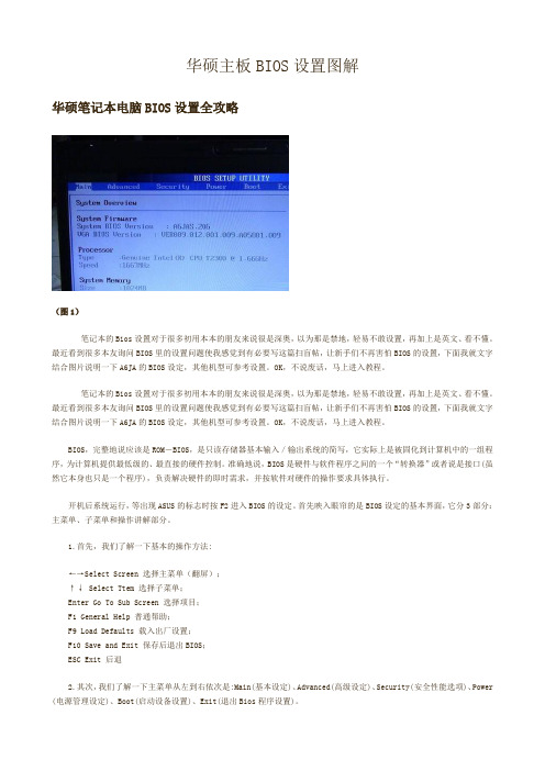
华硕主板BIOS设置图解华硕笔记本电脑BIOS设置全攻略(图1)笔记本的Bios设置对于很多初用本本的朋友来说很是深奥,以为那是禁地,轻易不敢设置,再加上是英文、看不懂。
最近看到很多本友询问BIOS里的设置问题使我感觉到有必要写这篇扫盲帖,让新手们不再害怕BIOS的设置,下面我就文字结合图片说明一下A6JA的BIOS设定,其他机型可参考设置。
OK,不说废话,马上进入教程。
笔记本的Bios设置对于很多初用本本的朋友来说很是深奥,以为那是禁地,轻易不敢设置,再加上是英文、看不懂。
最近看到很多本友询问BIOS里的设置问题使我感觉到有必要写这篇扫盲帖,让新手们不再害怕BIOS的设置,下面我就文字结合图片说明一下A6JA的BIOS设定,其他机型可参考设置。
OK,不说废话,马上进入教程。
BIOS,完整地说应该是ROM-BIOS,是只读存储器基本输入/输出系统的简写,它实际上是被固化到计算机中的一组程序,为计算机提供最低级的、最直接的硬件控制。
准确地说,BIOS是硬件与软件程序之间的一个“转换器”或者说是接口(虽然它本身也只是一个程序),负责解决硬件的即时需求,并按软件对硬件的操作要求具体执行。
开机后系统运行,等出现ASUS的标志时按F2进入BIOS的设定。
首先映入眼帘的是BIOS设定的基本界面,它分3部分:主菜单、子菜单和操作讲解部分。
1.首先,我们了解一下基本的操作方法:←→Select Screen 选择主菜单(翻屏);↑↓ Select Ttem 选择子菜单;Enter Go To Sub Screen 选择项目;F1 General Help 普通帮助;F9 Load Defaults 载入出厂设置;F10 Save and Exit 保存后退出BIOS;ESC Exit 后退2.其次,我们了解一下主菜单从左到右依次是:Main(基本设定)、Advanced(高级设定)、Security(安全性能选项)、Power (电源管理设定)、Boot(启动设备设置)、Exit(退出Bios程序设置)。
华硕电脑手册说明书

Important NoticesImproper handling of a vehicle , especially while raised and supported by jack stands, ramps or other mechanical means, can cause serious bodily injury or even death. It is strongly rec-ommended that a trained, experienced mechanic, with proper equipment, do the installation.The seller nor the manufacturer assumes no liability, expressed or implied, for the improper installation or use of this product or its components. Before using, the user shall determine the suitability of the products for it’s intended use. The user assume all responsibility and risk in connection there within.It is the buyer’s responsibility to have all suspension, drivetrain, steering, and other compo-nents checked for proper tightness and torque after the fi rst 100 miles and every 3,000 miles by a qualifi ed professional mechanic.Extreme care should be taken while operating your vehicle to prevent vehicle rollover or loss of control. Both can result in serious injury or death. Do not add or modify parts to this kit or use outside it’s intended purpose. Follow all safety regulations and warnings per state and federal laws.Note: Final fi tment of the wheel to caliper is the responsibility of the customer.Note: It is important to read and understand this ENTIRE installation manual, before starting the installation.Kit Contents1 Pair of calipers w/pads2 Rotors2 Retaining plate2 Preload spacers (C-clip applications)4 Caliper bolts8 T-bolts8 Nuts2 Disc brake mounting plate assembly (1 Left and 1 Right)1 stainless steel brake line kitTools and Equipment That May Be RequiredDifferent models and years of vehicle use different-sized fasteners, and every effort has been taken to correctly identify the proper sized tool for each step of the installation. Occasionally, however, manufacturers use alternate fasteners, so it’s advisable to check that each tool cor-rectly fi ts the fastener before loosening or tightening it. The following tools and equipment may be needed:9/16” socket wrench12mm socket14mm wrenchTorque wrenches capable of 10-148 lb-ft settingsSeveral ragsSmall funnel or suitable means of fi lling master cylinder reservoirBrake bleed bottle1 pair of jack stands or other means of supporting vehicleHydraulic pressPair of PliersStep 1-Remove WheelsWARNING - Brake fl uid will damage most painted surfaces. Immediately clean spilled brake fl uid from any painted surfaces. Be sure the cap is securely installed on the master cylinder. If the cap is loose or removed, it is likely more fl uid willdrip.Note: All Photographs Show Left Side Installation, unless noted otherwise.Break loose the lug nuts on both rear wheels before jacking up the car.Refer to the Owners Manual for the correct location when jacking up the vehicle. Jack up the vehicle and secure on a pair of jack stands. Never leave any vehicle supported with only a jack - always use jack-stands.After securing the vehicle at a convenient height, remove the rear wheels.Note: If you remove the bottom lug nut last while holding the bottom of the tire, it will lessen the chances of the wheel tilting on it’s own and make removal easier.Step 2 -Removal of Drum Brakes and AxleRemove brake drums from thebrake assembly.Remove the hard line from thewheel cylinder attached to thebacking plate.For c-clip applications- Removethe differential cover, unbolt thecross shaft and remove it from thevehicle. See factory service manualfor additional information.Using a 9/16” socket, remove thefour nuts that hold each axle shaftinto the axle and remove the axleshafts from the axle. Some leakagemay occur.Remove the backing plate from theaxle housing.Wipe clean grease and contami-nants from all surfaces.For semi-fl oat applications- Pressthe old bearings and seals fromthe axle shafts. C-clip applicationsdo not need the removal of the oldbearings and seals unless parts areneeded to be replaced.Install the disc brake mounting plate onto the axle flange with new supplied retaining bolts. The mounting plate is directional, insurethat the plate is installed on the correct side.Step 3 -Install Disc Mounting PlateIn order to install this kit, remove the factory bolts from the axle fl ange. If installing on a C-clip application do not remove the fac-tory bolts.Install the supplied bolts (longer than factory bolts) in the axle fl ange.Adjust the internal parking brake shoes with the adjuster until there is just enough room to slide the ro-tor over the shoes. Refer to the fac-tory service manual for additional information.STEP 4 -Install Axle ShaftsApply grease to the outside of the bearing seal assembly and slide the preload spacer onto the seal. The grease will help hold the spacer in place.Slide the axle shaft into the axle housing by hand, lining it up with the differential. The axle shaft should not be forced, damage mayoccur.On C-clip retained axles, slide the axles all the way into the axle hous-ing using care to avoid damage to the splines or the bearing surface. Reinstall the C-clip and the cross shaft. Ensure that all old silicone is cleaned from the differential hous-ing and the differential cover, and reinstall the differential cover using a new gasket or silicone. Fill thehousing with new oil.Using a hydraulic press, press the new bearing and retaining collar onto the axle shaft. Refer to the factory service manual for more details.Grease the shaft where the axle shaft seal will be installed, theninstall the seal.Install the retaining plate and new preload spacer on axle shaft. Notice the direction the preload spacer is facing in the photo to the right. The chamfer side faces inboard.STEP 5 -Install the Rotor and CaliperInstall the rotor on the axle.Install the brake pads in the caliper.Using a 12mm socket wrench in-stall the caliper onto the mounting plate. Torque the bolts to 15-18 ft-lbs.Line up the access holes located on the axle shafts with the retainer bolts. Using a 9/16” socket wrench tighten the four nuts to 25 - 30 ft-lbs.STEP 4 -(Continued)Install Axle ShaftsSTEP 6 -Install Stainless Steel Brake LinesInstall the caliper end of the stainless steel brake line by fi rst placing a copper crush washer on either side of the banjo fi tting.Insert the banjo bolt into the caliper using a 14mm wrench or socket to tighten it. Insert the stainless steel brake line fi tting through the chassis bracket, and screw it onto the hard line fi tting by hand a few turns, to ensure that it is properly engaged. Tighten the hard line fi tting.Check to ensure that the brake line is not binding in any way, nor interfering with any suspension component.Note that you will need to purchase shorter metal brake lines from an automotive pats supplier.If the brake line is not properly routed, a catastrophic failure could occur. If you are unsure that the line is routed properly and safely, do not drive the car. Please call our Tech Support Dept. for assistance if you have any doubt as to the brake line routing.Install the emergency brake cable at the mounting plate and adjust, refer to the factory service manual.If realignment is necessary, loosen the banjo bolt, and realign the brake line, or loosen the inboard end of the line, and slightly re-clock the fitting.Weld the brake line mounting tab onto the axle tube. Install the brake line through the tab and install the c-clip to secure the line.STEP 7-Bleed BrakesComplete installation on both sides of the vehicle before bleeding the system. Note: The calipers and lines will need to fi ll with fl uid, quickly draining the master cylinder reservoir. Keep a close watch on the fl uid level when initially bleeding the system. Do not allow the master cylinder reservoir to run dry and draw in air. Doing so may require the brake system to be serviced by a certifi ed brake technician.Refer to owners manual for torque used on bleed screws.After initially bleeding the system, gently tap the caliper body with a non-marring mallet or hammer to dislodge any small air bubbles and re-bleed.After bleeding, apply a constant pressure to the brake pedal and check all connections, including bleed screws, and both ends of the line for leaks.Brake fl uid will damage most painted surfaces. Immediately clean spilled brake fl uid from any painted surface, including the caliper. Though caliper paint is designed to resist harsh chemicals, prolonged exposure will damage the fi nish.STEP 8-Reinstall wheelsCheck wheel to caliper clearance before installing wheels!Reinstall the wheels and torque the lug nuts to your wheel manufacturer’s specifi cations. It may be necessary to snug the bolts before lowering the vehicle and then torque the wheels when the car is on the ground. Alternatively, an assistant may depress the brake pedal while you tighten the wheel nuts to the proper torque setting.Carefully test-drive the vehicle in a safe area at low speed to insure all components are working correctly.。
华硕笔记本电脑产品说明书
1、启动阶段1)红灯每2秒闪一次,且伴为“哔-,哔-”警示音:电调未检测到油门信号。
2)绿灯闪烁N次:上电时自动进行锂电节数检测,闪烁N次表示当前锂电为N节。
2、行驶阶段1)油门摇杆处于中点区域,红色和绿色LED均熄灭。
2)前进时,红色LED恒亮;当油门处于正向最大(100%油门)时,绿色LED也会点亮。
3)倒退时,红色LED恒亮。
3、相关保护功能触发时,LED状态含义:1)红灯持续闪烁(单闪,“☆,☆,☆”方式闪烁):电池电压太低,电调进入电池低压保护状态。
2)绿灯持续闪烁(单闪,“☆,☆,☆”方式闪烁):电调温度过高,电调进入过热保护状态。
故障现象解决方法可能原因1、电池电压没有输入到电调;1、检查电池与电调是否连接可靠,如有焊接不良,请重新焊好;上电后电机无鸣音,指示灯也未闪亮06编程设定说明08电调状态指示灯(LED)说明09保护功能说明10故障快速处理01声明Seaking Pro 120A • Seaking Pro 160A船用无刷电子调速器使用说明书· 调试请将船模架起,确保船桨不会碰到人或其他物体,以免发生安全事故。
03产品特色· 轻量化设计,适合竞赛要求。
· 出色的防水性能(160A电调采用塑封工艺,120A电调采用纳米镀膜工艺),一般情况下无需做防水处理即可直接使用(注:使用后请将电调插头吹干,以免锈蚀)。
· 内置超强开关模式BEC,持续电流达到4A,瞬间达到8A,且支持 6V和7.4V 切换,轻松驱动各种强力舵机及高压舵机。
· 采用好盈专利铜片导热技术,配合水冷模块和极低热阻的内部MOSFET,使得电调的耐流能力及可靠性大大增强。
· 使用顶级竞赛核心程序,具有一流的操控手感及丰富的调节选项,适应各种比赛环境。
· 行业首创的超速功能(即:开启Turbo进角),让马达瞬间释放更强动力,轻松超越竞争对手。
K8NF4 系列主板 简体中文说明书

K8NF4系列主板nVIDIA® nForce 4 Ultra / Standard / 4X支援Socket 939AMD® Athlon TM 64 /Athlon TM 64 FX处理器简体中文使用手册z主板尺寸(本主板属 ATX 规格)z194mm x 295mm (宽与长)z操作系统 (Operating System)z支援Windows® 2000/XP作业平台K8NF4 系列主板安全须知0此手册之所有图片仅供参考,请以您手边的主板为主。
0在安装主板时,请勿连接任何电源,以防止通电造成伤害。
0此主板中许多精密的积体电与组件所组成,为避免受到静电影响,请配戴防静手环。
0请尽量避免碰触主板上的集成电路与组件。
0在拆装任何内部硬设备时,请先拔除 AC电源线,待拆装完成后再行接回电源,以避免拆装过程中发生短路或造成危险。
包装内容与配件K8NF4 Series主板IDE 排线/ FDC 排线SATA 电源线/ SATA 排线USB 连接线(选择性配备)SPDIF & FRONT AUDIO Port 连接线(选择性配备)ABS适配卡(选择性配备)I/O 檔板安装用驱动程序光盘片K8NF4 Series主板使用手册符号提示警告、注意 … 请依步骤进行…K8NF4 系列主板目录第一章 简介 (1)主板简介 (1)规格简介 (2)配置图 (5)K8NF4系列主板组件图 (5)硬件安装 (6)安装中央处理器 (6)安装内存 (7)后方面板配置 (10)前方面板接脚配置: SW/LED、SPEAKER (12)连接器配置 (Connectors) (13)接脚、跳线器(Headers & Jumpers) (14)音效功能介绍 (18)扩充插槽 (Slots) (19)安装电源供应器 (20)第二章 主板 BIOS 系统设定 (21)简介 (21)第三章 安装软件设定 (23)软件列表 (23)安装软件步骤 (23)附录Ⅰ:5.1声道设定 (25)附录Ⅱ:SATA RAID0/1设定 (26)K8NF4 系列主板第一章简介主板简介感谢您选择了K8NF4 Series 主板!K8NF4 Series主板是分别建构于nVIDIA® nForce 4 Ultra / Standard / 4X芯片。
华硕笔记本使用手册
Acrobat 7.0
Office 2003
靈格斯翻譯專家
WinRAR壓縮軟件
迅雷5多特版
QQ 2009SP6正式版
Windows live MSN+Mail2009
快播
PPS
迅雷看看(可是邊看邊下載)
千千靜聽
紫光拼音輸入法
中華漢碼
備用軟件(此類軟件不到非用不可時絕不允許安裝)
4、字型以常用國字表中的楷體字形為主,一些舊字形如 眞 淸等刪除.
5、異體字的取捨依台灣標準,個別自己極為喜歡的異體字(日常經常書寫)可以保留如,此類字可以做一個列表出來,即輸入法和書寫上存在一定差異的.此類單字需隱藏起來。
6、刪除日韓漢字因為根本就用不到。
異體字的取捨是自己應用中文最為困擾的問題,自己應用繁體字的初衷也僅僅是因為對傳統中國文化的熱愛,並非搞復古主義或借此來與港台人交流。整理出自己常用的繁體字表出來有一定的實用性,可以為自己應用中文提供一個指導和標準。
關於繁體字的應用,台灣和香港兩地的標準略有差異,在碼表中均做收錄,輸入法碼表原則上以台灣的《常用國字表》為準,個別自己已經習慣的字,在香港是正體,在台灣是異體如:溼,裏,卧 等均列入收錄範圍。
香港政府頒佈的《香港常用字形表》4759個單字,只用於個人書寫應用,其標準不像台灣的《常用國字表》那麼嚴格,是很好的傳統中文書寫參考資料。
Windows 7系統注意事項
1.關閉系統自動檢查更新。
2.將Windows 7主題設定為自己已做好的Windows 7宋體版主題。
3.通過360安全衛士將IE首頁改為“”4.除必備驅動程式外,華碩自帶光盤裏的應用軟件,用不到的盡量不裝.
asus使用手册
第六章:附錄
6-1 藍牙鼠標設置步驟(選配)........................................... 66 6-2 簡易故障排除. ...................................................................... 68
C5462
筆記本電腦
硬件使用手冊
HDMI
E-SATA
2010 年 4 月
版權說明
版權所有.不得翻印 © 2010 華碩電腦 本使用手冊包括但不限於其所包含的所有���� 信息�� 受到著作權法之保護,未經 華碩電腦股份有限公司(以下簡稱“華碩”)許可,不得任意地仿製、拷貝、 謄抄、轉譯或為其他使用或處分。
第一章:認識您的電腦
1-1 1-2 1-3 1-4 1-5 1-6 外觀介紹................................................................................ 10 選購配件說明. ...................................................................... 16 日常維護保養. ...................................................................... 17 外出使用................................................................................ 20 個人數據備份. ...................................................................... 22 安全防護功能(選購).................................................... 24
华硕主板用户手册
PARALLEL PORT
VGA1 USB12
USBPW34 USBPW12
LAN_USB34
ATI RC410
Top:Line In Center:Line Out CHA_FAN1 Below:Mic In
RTL8111B
PCIEX1_1
AUX
TV_C
PCIEX16 P5RD2-VM
CR2032 3V Lithium Cell CMOS Power
CLRTC
12
23
Normal (Default)
Clear CMOS
1-22
P5RD2-VM
®
USBPW34 USBPW12
2 1
+5V (Default)
3 2
+5VSB
USBPW56 USBPW78
12
23
P5RD2-VM USB Device Wake-Up
+5V (Default)
+5VSB
华硕主板用户手册华硕主板华硕主板bios设置图解华硕主板官网华硕主板驱动华硕主板bios升级工具华硕b85主板华硕h81主板华硕服务器主板技嘉和华硕主板哪个好
P5RD2-VM
Motherboard
C2365 © 2006
2
3
4
® ®
®
5
• • • • • •
• • • • • •
6
• • •
1-26
• •
P5RD2-VM
®
P5RD2-VM IDE Connectors
PIN 1
PRI_IDE SEC_IDE
1-27
P5RD2-VM
®
华硕 PTGD1-LA (Grouper-GL8E) 说明书

PTGD1-LA (Grouper-GL8E) User GuideContentsPTGD1-LA specifications summary (iii)1.Motherboard layout (1)2.Central Processing Unit (CPU) (2)3.System memory (4)4.Expansion slots (6)5.Jumpers (8)6.Connectors (9)6.1Rear panel connectors (9)6.2Internal connectors (11)iiPTGD1-LA specifications summary* Specifications are subject to change without noticeiiiiv1.Motherboard layoutASUS PTGD1-LA (Grouper-GL8E) motherboard12ASUS PTGD1-LA (Grouper-GL8E) motherboard2.Central Processing Unit (CPU)The motherboard comes with a surface mount LGA775 socket designed for the Intel ® Pentium ® 4 processor in the 775-land package with 1MB L2cache. The processor, built on the 90-nanometer manufacturingtechnology, supports 800MHz front side bus (FSB), Intel ® HyperthreadingTechnology, and core speeds of up to 3.4GHz.Before installing the CPU, make sure that the cam box is facing towards you and the load lever is on your left.3.Lift the load lever in thedirection of the arrow.Remove the cap only after the CPU is installed to prevent bending anddamaging the socket connectors.4.Lift the load plate from the corner with your thumb.To install a CPU:1.Locate the LGA775 socket on the motherboard.2.retention tab.R e t e n t i o n t a bL o a d l e v e rT h i s s i d e o f t h e c a m b o x s h o u l d f a c e y o u.P n P C a pL o a d p l a t eASUS PTGD1-LA (Grouper-GL8E) motherboard 35.Position the CPU over the socket, making sure that the gold triangle is on the bottom-left corner of the socket. The socket alignment keyshould fit into the CPU notch.The CPU fits in only one correct orientation. DO NOT force the CPU into the socket to prevent bending the connectors on the socket anddamaging the CPU!6.Use both thumbs to carefully push out the PnP cap from the load plate window.7.Close the load plate, then push the load lever until itsnaps into the retention tab.A l i g n m e n t k e yG o l d t r i a n g l e m a r kABYou can also remove the PnP cap by pushing out its top corner.4ASUS PTGD1-LA (Grouper-GL8E) motherboard3.System memoryThe motherboard comes with four Double Data Rate (DDR) Dual InlineMemory Module (DIMM) sockets. These sockets support up to 4GB system memory using 184-pin unbuffered non-ECC 2.6V DDR SDRAM.The following figure illustrates the location of the DDR DIMM sockets.Memory configurationsYou can install 128MB, 256MB, 512MB, and 1GB DDR SDRAM DIMMs into the DIMM sockets using the memory configurations in this section.Important notes on memory configurations•Installing DDR DIMMs other than the recommended configurations may cause memory sizing error or system boot failure. Use any of the recommended configurations in Table 1.•Install only i i d e n t i c a l (the same type and size) DDR DIMM pairsusing the recommended configurations.•Make sure that the memory frequency matches the CPU FSB (Front Side Bus). Refer to Table 2 on the next page.•This motherboard does not support double-sided 16-bit DDR DIMMs.•Do not create a three-DIMM configuration in dual-channel mode. Thethird DIMM is ignored in the dual-channel operation.PTGD1-LA 184-Pin DDR DIMM SocketsD I M M _A 1D I M M _A2D I M M _B 1D I M M _B2ASUS PTGD1-LA (Grouper-GL8E) motherboard 5Make sure to unplug the power supply before adding or removing DIMMs or other system components. Failure to do so can cause severe damage to both the motherboard and the components.Follow these steps to install a DIMM.1.Unlock a DIMM socket by pressing the retaining clips outward.2.Align a DIMM on the socket such that the notch on the DIMM matches the break on the socket.3.Firmly insert the DIMM into the socket until the retaining clips snap back in place and the DIMM is properly seated.Installing a DIMMTable 1Recommended memory configurationsTable 2Memory frequency/CPU FSB synchronization* U s e o n l y i d e n t i c a l D D R D I M M p a i r s.U n l o c r e t a i n i c l i pD D R D I M M n o t c h4.Expansion slotsThe motherboard has one PCI Express and three PCI slots.To install and configure an expansion card:1.Install an expansion card following the instructions that came with thechassis.2.Turn on the system and change the necessary BIOS settings, if any.3.Assign an IRQ to the card. Refer to the tables below.4.Install the drivers and/or software applications for the expansion cardaccording to the card documentation.Standard interrupt assignments6ASUS PTGD1-LA (Grouper-GL8E) motherboardPCI slotsThere are three 32-bit PCI slots on this motherboard. The slots support PCI cards such as a LAN card, SCSI card, USB card, and other cards thatcomply with PCI specifications.PCI Express slotThis motherboard has one PCI Express slot, which supports a 164-pin x16interface graphics card.IRQ assignments for this motherboardClear password (3-pin CLPWD)This jumper allows you to clear the password if you forgot your password.5.JumpersClear RTC RAM (3-pin CLRTC)This jumper allows you to clear the Real Time Clock (RTC) RAM in CMOS. You can clear the CMOS memory of date, time, and system setup parameters by erasing the CMOS RTC RAM data. The onboard button cell battery powers the RAM data in CMOS, which include system setup information such as system passwords.To erase the RTC RAM:1.Turn OFF the computer and unplug the power cord.2.Move the jumper cap from pins 2-3 (Normal) to pins 1-2 (ClearCMOS). Keep the cap on pins 2-3 for about 5~10 seconds, then move the cap back to pins 2-3.3.Plug the power cord and turn ON the computer.4.Hold down the <Del> key during the boot process and enter BIOSsetup to re-enter data.Except when clearing the RTC RAM, never remove the cap from thedefault position. Removing the cap will cause system boot failure!CLRTCNormal Clear CMOS(Default)PTGD1-LA Clear Password SettingCLPWDNormal(Default)236.Connectors6.1Rear panel connectors1.PS/2 mouse port.PS/2 mouse port. This green 6-pin port is for a PS/2 mouse.2.Parallel port.Parallel port. This 25-pin port connects a parallel printer, a scanner, or other devices.3.IEEE 1394 port.IEEE 1394 port. This 6-pin IEEE 1394 port provides high-speedconnectivity for audio/video devices, storage peripherals, PCs, orportable devices.4.RJ-45 port.RJ-45 port. This port allows connection to a Local Area Network(LAN) through a network hub.5.Side Speaker Out port.Side Speaker Out port. This Side Speaker out (gray) portconnects to the side speakers in an 8-channel audio configuration. 6.Rear Speaker Out port.Rear Speaker Out port. This Rear Speaker (black) port connects to the rear speakers on a 4-channel, 6-channel, or 8-channel audioconfiguration.7.Center/Subwoofer port.Center/Subwoofer port. This Center/Subwoofer (yellow orange) port connects to the center/subwoofer speakers.8.Line In port.Line In port. This Line In (light blue) port connects a tape player or other audio sources.9.Line Out port.Line Out port. This Line Out (lime) port connects a headphone or a speaker. In 4-channel, 6-channel, and 8-channel mode, the function of this port becomes Front Speaker Out.10.Microphone port.Microphone port. This Mic (pink) port connects a microphone.B 2.0 ports 3 and B 2.0 ports 3 and 4. These two 4-pin Universal Serial Bus(USB) ports are available for connecting USB 2.0 devices.B 2.0 ports 1 and 2.USB 2.0 ports 1 and 2. These two 4-pin Universal Serial Bus (USB) ports are available for connecting USB 2.0 devices.13.Video Graphics Adapter port.Video Graphics Adapter port. This 15-pin port is for a VGA monitor or other VGA-compatible devices.14.S/PDIF Out port.S/PDIF Out port. This port is the digital output interface for external audio devices. It supports S/PDIF devices that provide 6- or 8-channel surround sound and 3D audio.15.S/PDIF In port. S/PDIF In port. This port is the digital input interface for externalaudio devices. It supports S/PDIF devices that provide 6- or 8-channel surround sound and 3D audio.16.PS/2 keyboard port.PS/2 keyboard port. This purple connector is for a PS/2 keyboard.Audio 2, 4, 6, or 8-channel configuration6.2Internal connectorsThis section describes and illustrates the internal connectors on the motherboard.1.Floppy disk drive connector (34-1 pin FLOPPY)This connector supports the provided floppy drive ribbon cable. After connecting one end to the motherboard, connect the other end to the floppy drive. (Pin 5 is removed to prevent incorrect insertion when using ribbon cables with pin 5 plug).NOTE: Orient the red markings on the floppy ribbon cable to PIN 1.PTGD1-LA Floppy Disk Drive ConnectorFLOPPY2.IDE connector (40-1 pin IDE)This connector supports the provided UltraDMA100/66 IDE hard disk ribbon cable. Connect the cable’s blue connector to the IDE connector,then connect the gray connector to the UltraDMA100/66 slave device (hard disk drive) and the black connector to the UltraDMA100/66 master device.•Pin 20 on the IDE connector is removed to match the covered hole on the UltraDMA cable connector. This prevents incorrect orientation when you connect the cables.•The hole near the blue connector on the UltraDMA100/66 cable isintentional.PTGD1-LA IDE ConnectorNOTE: Orient the red markings (usually zigzag) on the IDE ribbon cable to PIN 1.4.S erial ATA connectors (7-pin SATA1, S (7-pin SATA1, SATA2, SATA3, SATA4)ATA2, SATA3, SATA4)These connectors support the thin Serial ATA cables for Serial ATA hard disks. The current Serial ATA interface allows up to 150 MB/s data transfer rate, faster than the standard parallel ATA with 133 MB/s (Ultra ATA133).3.ATX power connectors (24-pin ATXP ATX power connectors (24-pin ATXPW W R R, 4-pin ATX12V), 4-pin ATX12V)These connectors are for an ATX 12V power supply. The plugs from the power supply are designed to fit these connectors in only one orientation. Find the proper orientation and push down firmly until the connectors completely fit.In addition to the 24-pin ATXPWR connector, this motherboardrequires that you connect the 4-pin ATX +12V power plug to provide sufficient power to the CPU.Make sure that your ATX 12V power supply can provide 8A on the +12V lead and at least 1A on the +5-volt standby lead (+5VSB). The minimum recommended wattage is 230W, or 300W for a fully configured system.The system can become unstable and might experience difficultypowering up if the power supply is inadequate.PTGD1-LA SATA ConnectorsG N R S A T A _T X P R S A T A _T X N G N R S A T A _R X P R S A T A _R X N G N SATA3SATA2SATA15.IEEE 1394 connector (10-1 pin FRONT_1394)This connector is for a 10-to-6-pin 1394 serial connector cable that connects to a 1394 module. Attach the 10-1 pin cable plug to this connector, and the 6-pin cable plug to the 1394 module. You can also connect a 1394-compliant internal hard disk to this connector.6.USB connectors (10-1 pin FRONT_USB1, FRONT_USB2)If the USB ports on the rear panel are inadequate, two USB connectors are available for additional USB ports. The USB headers comply with USB 2.0 specification that supports up to 480 Mbps connectionspeed. This speed advantage over the conventional 12 Mbps on USB 1.1 allows faster Internet connection, interactive gaming, andsimultaneous running of high-speed peripherals. You can connect a USB module to any of the USB connectors.The USB module is purchased separately.PTGD1-LA FRONT_1394 ConnectorFRONT_1394G N+12T P B G N T P A 12V P B +N D P A +PTGD1-LA USB 2.0 ConnectorsFRONT_USB1N D S B _P 5+S B _P 5-S B +5VN G N U S B _P 6U S B _P 6U S B +5FRONT_USB2N D S B _P 5+S B _P 5-S B +5V N G N U S B _P 6U S B _P 6U S B +58.Fan connectors (3-pin SYS_FAN, 4-pin CPU_FAN)The fan connectors support cooling fans of 350mA~740mA (8.88W max.) or a total of 1A~2.22A (26.64W max.) at +12V. Connect the fan cables to the fan connectors on the motherboard, making sure that the black wire of each cable matches the ground pin of the connector.Do not forget to connect the fan cables to the fan connectors.Insufficient air flow within the system can damage the motherboard components. These are not jumpers! DO NOT place jumper caps on thefan connectors!7.DDR DIMM connectors (184-pin DIMMA1, DIMMA2,DIMMB1, DIMMB2)These four 184-pin DIMM sockets support up to 4GB system memory using unbuffered ECC PC3200/2700/2100 DDR DIMMs.PTGD1-LA 184-Pin DDR DIMM SocketsD I M M _A 1D I M M _A2D I M M _B 1D I M M _B2PTGD1-LA Fan ConnectorsCPU_FANSYS_FANGND Rotation+12V PWNGND Rotation +12V9.Internal audio connectors (4-pin CD-IN, F_LINE_IN)These connectors allow you to receive stereo audio input from sound sources such as a CD-ROM, TV tuner, or MPEG card.10.Front panel audio connector (10-1 FRONT_PANEL)This is an interface for the front panel audio cable that allows convenient connection and control of audio devices.PTGD1-LA Internal Audio ConnectorsCD_IN (Black)F_LINE_IN (White)R i g h t A u d i o C h a n n eL e f t A u d i o C h a n n e G r o u n G r o u n R i g h t A u d i o C h a n ne L ef t A u d i o C h a n n e G r o u n G r o u nPTGD1-LAFront Panel Audio Connector11. Front headphone connector (10-1 pin FRONT_AUDIO)This connector is for a chassis-mounted front panel headphone port.PTGD1-LAFront HeadPhone & MIC-IN Header Connector AUD_RET_AUD_RET_AUD_VCAUD_GN UD_FPOUT_LUD_MIC_JDUD_FPOUT_RUD_MIC2UD_MIC1。
华硕(Asus)电脑配件产品说明书
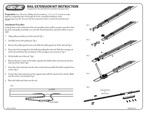
RAIL EXTENSION KIT INSTRUCTION
A Supplement To The Chain/Belt Drive Assembly & Instruction Poster
Preparation: You will need a Phillips Head Screwdriver, 7/16” & 1/4” wrench or socket.
7. Insert the chain extension into the (door end) and reassemble the bullet using the four screws. Fig. 6
8. Connect the chain extension to the original chain with the master link as shown. Make
38408502752
10. At the door end of the rail, slide the carriage back into the rail. Make sure the door arrow points toward the door. Fig. 7