福斯Logix3200IQ智能定位器调试说明
Logix520智能定位器的调校
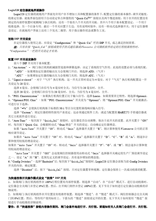
Logix520定位器就地界面操作Logix520定位器的就地用户界面允许用户在不增加工具和配置器的条件下,配置定位器的基本操作,调节灵敏度,校准定位器。
就地界面包括用于自动设定零点和量程的“Quick-Cal TM”按钮以及两个慢进按钮,用于在开的位置没有固定的内部停装置时观测阀门/执行机构。
还有一个装有八个开关的开关板。
其中六个用于基本配置设定,一个用于校准选择,另一个后备专用。
最后一个开关应置于左边,另有说明时除外。
还有一转动式选择器开关,用于定位器增益设定。
在就地用户界面上还有三个发光二极管,用于指示操作状态或警告工况。
初始DIP开关设定在定位器投入使用之前,应设定“Configuration”和“Quick_Cal”栏的DIP开关, 成之满足控制需要。
注:只有在按“Quick_Cal”按钮或使用手持式通信器或Flowserve公司微机软件给定的行程校准特性时,“Configuration”一栏的开关设定才有效。
配置DIP开关设定操作前六个DIP开关用于基本配置。
1、“Air Action”–阀门/执行机构机械接管连接和弹簧选择,决定了系统的空气作用。
此处的设置必须与系统匹配。
“ATO”–如果增加定位器的输出压力会使阀门开启,则选择ATO。
(气开)“A TC”–如果增加定位器的输出压力会使阀门关闭,则选择A TC。
(气关)2、“Signal at closed”–对于“气开”执行机构,这一开关正常时设定为4毫安,对于“气关”执行机构配置这一开关设定为20毫安。
选择4毫安,会使阀门在信号为4毫安时全关;当信号为20毫安时,全开。
选择20毫安,会使阀门在信号为20毫安时,全关;当信号为4毫安时,全开。
3、“POS. Charaterization”–如果执行机构位置正比于输入信号,选择Linear。
如果需要其它特性,则选择Optional。
4、“Optional POS. Char”–如果“POS. Charaterization”开关设为“Optional”,则“Optional POS. Char”开关被激活,可进行以下选择:选择“=%”会使执行机构基于标准的30:1等百分比量程曲线响应输入信号。
福斯定位器Logix 520MD+调试

福斯定位器Logix 520MD+调试
DIP开关
1、Air Action ATO:气开阀;
ATC:气关阀;
2、Valve action Double:双作用执行机构;
Single:单作用执行机构;
3、Signal at closed 4mA:4mA全关,通常用于气开阀;
20mA:20mA全关,通常用于气关阀;
4、Characterization Linear:线性特性
Other:其他 Air 通过LCD菜单、手操器或ValveSight(DTM)来选择。
5、Auto tune On:自动调整增益,根据自动校验期间的阀门响应时间来决定 PID增益(B-J);实际增益= Gain X 校验时的响应参数;
Off:固定为工厂设定的增益(B-J);
6、Valve stability Lo Friction:低摩擦力设定;
Hi Friction:高摩擦力设定;
7、Quick Calibration
Auto;定位器根据阀门或执行机构的机械限位,自动确定0%和100%的位置。
Jog;定位器根据阀门或执行机构的机械限位,自动确定0%的位置,对于100%位置由用户设定(校验期间需要操作人员的干预)。
福斯FLOWSERVE阀门定位器

福斯FLOWSER阀门定位器福斯定位器配置指南福斯(FLOWSERV阀门定位器调试方法(锦菲特I3599429OO2)[Q-Q,6696 22933]flowserve 阀门、Flowserve 3400IQ 定位器、LOGIX500、LOGIX510、LOGIX520 D3系列P-5 气动定位器电动气动数字-通用,IS和EXHART、Profibus 、Foundation 现场总线反馈机组、限位开关比如PP5XX-HPGU-23K01-PV9DA-3ZPMV P-1700 系列阀门专为腐蚀或高温环境应用设计,其所有外部零件均由不锈钢制造而成。
P-1700 和1720 型阀门的内部零件采用不锈钢制造,而P-1710 和P-1730 型阀门的内部零件则采用铝制。
P-1720 和P-1730 型阀门具有超高的空气传送能力。
P-1700 系列阀门专为双向操作应用设计,不过也可通过旋动一个阀座轻松实现单向操作。
不锈钢磁场外壳内的PMV I/P转换器很容易安装在P-1700 系列阀门上。
P-1500 P-1520P-1700 P-1720P-1710 P-1730Digital 具有PID 控制的2000 数字定位器品牌Logix说明福斯Logix 2000 是一款具有板载PID 控制的数字定位器。
通信方式为4-20mA 或Modbus。
阀门上安装的PID 控制器每秒更新阀杆位置16 次,从而减少了控制系统延迟。
Logix 3200IQ 数字定位器3200IQ-10-D6-M-04-40-0G-0F 3200IQ-10-D6-M-04-40-0G-00品牌Logix说明福斯Logix 3200IQ 数字HART? 定位器使用先进的piezo 技术提供一流的性能和可靠性。
通过使用本地按钮、HART手持设备和SoftTools 软件可轻松配置Logix 3200IQ 。
LOGIX 3201IQ定位器P/N : 215809.999.000,SN 4107028LOGIX 3202IQ定位器P/N : 221734.999.000,SN 4907010LOGIX 3203IQ定位器P/N : 216428.999.000,SN 610727 定位器P/N:215809.999.000,SN:55070043400IQ Digital Positioner品牌Logix说明The Flowserve Logix 3400 Series digital Foundation? Fieldbuspositioner utilizes state-of-the-art piezo technology to provide …500 数字定位器品牌Logix说明福斯Logix 500 数字定位器是下一代本质安全型Logix 500 系列的代表。
logix 3200MD(IOM)(Chinese)
使用说明书数字式定位器3200MD安装操作维护目录1 安全相关术语 32 基本信息 33 拆除包装与储藏 3 3.1 拆除包装 3 3.2 储藏 33.3 安装前的检查 34 Logix 3200MD定位器简介 4 4.1 规格 4 4.2 定位器操作 64.3 详细的定位器操作顺序75 安装8 5.1 安装到Valtek Mark One直通控制阀上8 5.2 安装到标准型Valtek转行程阀上9 5.3 可选的Valtek转行程安装程序 115.4 定位器和执行器的管路连接 116 布线与接地指南 12 6.1 4-20毫安指令输入布线 13 6.2 接地螺钉 13 6.3 顺从电压 13 6.4 电缆要求 136.5 本质安全栅 147 启动调试 14 7.1 Logix 3200MD就地用户面板 14 7.2 初始DIP开关设定操作 14 7.3 DIP开关设定的配置操作 15 7.4 快速校准操作模式下校准Dip开关的设置 16 7.5 快速校准(QUICK-CAL)操作 16 7.6 阀门位置的就地控制 17 7.7 恢复出厂设置 17 7.8 指令重置 17 7.9 版本号检查 17 7.10 Logix 3200MD状态 17 7.11 ValveSight配置、诊断软件和HART375手操器 18 8 维护与维修 21 8.1 驱动器模块组件 21 8.2 调节器 23 8.3 检查或设定内部调节器压力 24 8.4 滑阀 25 8.5 滑阀盖 25 8.6 滑阀阀杆位置传感器 26 8.7 主板PCB组件 27 8.8 压力传感器板 278.9 用户接线板 289 可选硬件 29 9.1 电位器排气口设计 29 9.2 HART调制调解器 309.3 4-20毫安模拟量输出板 3010 零部件列表 3211 Logix 3200MD备件箱 3412 Logix 3200MD安装套件 35 12.1 Valtek安装套件 35 12.2 Logix O.E.M.安装套件 3612.3 NAMUR标准安装套件附件的零件号 3613 常见问题解答 3714 订购详情 3815 故障排除 391 安全相关术语安全术语危险、警告、小心和注意在本说明书中被用来强调特定危险和/或提供与那些很可能出现的危险相关的更多信息。
Flowserve-Logix MD+智能阀门定位器
Flowserve-Logix MD+智能阀门定位器李宝华摘要:福斯(Flowserve)旗下的Logix品牌专门生产数字式智能阀门定位器,在控制阀的数字控制方面技术领先,产品体现了创新、高质量和高性能,其Logix MD+型是响应市场需求,在原有MD型上的固件升级,支持HART通信,提供三个诊断功能层级,嵌入V alveSight™ FDT/DTM技术,LCD显示和LED状态灯,可选单作用或双作用,本文对Logix 500 MD+的工作原理和应用进行探讨关键词:Logix MD+;智能阀门定位器;工作原理;应用引言福斯(Flowserve)公司是全球流体设备和控制的领军厂商,为电力、石油、天然气、化工及其它行业提供泵、密封、流体控制(阀门)以及自动化控制和服务,拥有众多业内知名的传统品牌和广泛的流体控制产品。
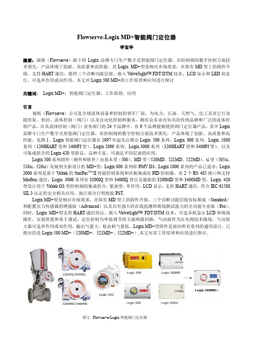
在其流体控制(阀门)业务部门的24个品牌中,有9个品牌能够提供阀门定位器产品,其中Logix 品牌专门生产数字式智能阀门定位器,在控制阀的数字控制方面技术领先,产品体现了创新、高质量和高性能,见图1。
Logix智能阀门定位器从1997年起先后推出Logix 500系列、Logix 800系列、Logix 1000系列(1200HART型和1400Ff型)、Logix 2000系列、Logix 3000系列(3200HART型和3400Ff型),以及可集成组合的Logix 420型新品,品种丰富,可满足不同层面的应用。
Logix 500系列固件(硬件和软件)由基本型(500)、MD型(520MD、521MD、522MD)、si型(505si、510si、520si)发展到全新设计的MD+型;Logix 800系列即PMV D3;Logix 1000系列的产品已退市;Logix 2000系列是基于V altek的StarPac TM II智能控制系统和在板集成有PID控制器,有2个RS 485接口和支持Modbus通信;Logix 3000系列有3200IQ型和3400IQ型以及最新的3200MD型和3400MD型。
福斯定位器配置指南
福斯定位器配置指南福斯(FLOWSERVE)阀门定位器调试方法(锦菲特I3599429OO2)[Q-Q,6696 22933]flowserve阀门、Flowserve 3400IQ定位器、LOGIX500、LOGIX510、LOGIX520、D3系列P-5 气动定位器电动气动数字- 通用,IS 和EXHART、Profibus、Foundation 现场总线反馈机组、限位开关比如PP5XX-HPGU-23K01-PV9DA-3ZPMV P-1700 系列阀门专为腐蚀或高温环境应用设计,其所有外部零件均由不锈钢制造而成。
P-1700 和1720 型阀门的内部零件采用不锈钢制造,而P-1710 和P-1730 型阀门的内部零件则采用铝制。
P-1720 和P-1730 型阀门具有超高的空气传送能力。
P-1700 系列阀门专为双向操作应用设计,不过也可通过旋动一个阀座轻松实现单向操作。
不锈钢磁场外壳内的PMV I/P 转换器很容易安装在P-1700 系列阀门上。
P-1500 P-1520P-1700 P-1720P-1710 P-1730Digital具有PID 控制的2000 数字定位器品牌Logix说明福斯Logix 2000 是一款具有板载PID 控制的数字定位器。
通信方式为4-20mA 或Modbus。
阀门上安装的PID 控制器每秒更新阀杆位置16 次,从而减少了控制系统延迟。
Logix3200IQ 数字定位器3200IQ-10-D6-M-04-40-0G-0F3200IQ-10-D6-M-04-40-0G-00品牌Logix说明福斯Logix 3200IQ 数字HART? 定位器使用先进的piezo 技术提供一流的性能和可靠性。
通过使用本地按钮、HART 手持设备和SoftTools软件可轻松配置Logix 3200IQ。
LOGIX 3201IQ定位器P/N:215809.999.000,SN:4107028LOGIX 3202IQ定位器P/N:221734.999.000,SN:4907010LOGIX 3203IQ定位器P/N:216428.999.000,SN:610727定位器P/N:215809.999.000,SN:55070043400IQ Digital Positioner品牌Logix说明The Flowserve Logix 3400 Series digital Foundation? Fieldbuspositioner utilizes state-of-the-art piezo technology to provide…500 数字定位器品牌Logix说明福斯Logix 500 数字定位器是下一代本质安全型Logix 500 系列的代表。
logix520福斯定位器说明书
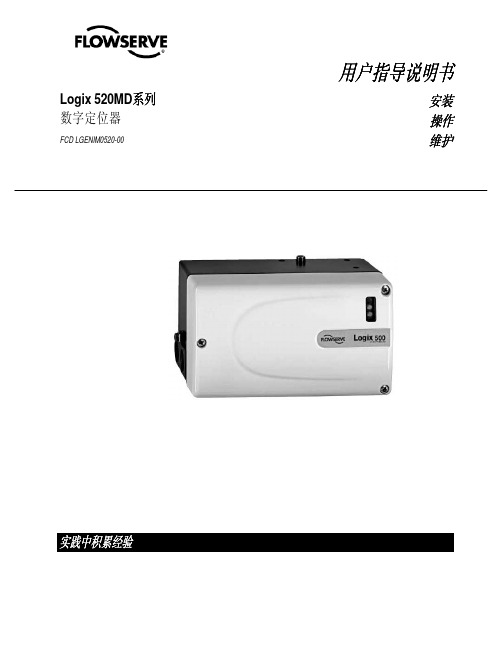
Logix 520MD系列数字定位器FCD LGENIM0520-00用户指导说明书安装操作维护实践中积累经验目录页码基本信息............................................................................................. 2 拆箱..................................................................................................... 3 Logix 520MD 概要............................................................................... 4 技术参数............................................................................................. 4 工作原理............................................................................................. 5 气路连接.............................................................................................. 6 接线..................................................................................................... 6 电缆要求.............................................................................................. 7 调试..................................................................................................... 8 Logix 520MD 就地界面操作............................................................ 8 配置Dip 开关设置的操作................................................................ 8 校准开关........................................................................................ 9 快速校准操作................................................................................. 9 恢复出厂设置................................................................................. 10 4-20 mA 模拟输出板....................................................................... 10 错误代码.............................................................................................. 12 故障排除.............................................................................................. 15 限位开关............................................................................................. 16 备件包................................................................................................. 17 尺寸图. (18)1 正确使用福斯阀门福斯阀门、、执行执行器和附件器和附件 1.1手册手册使用使用使用说明说明以下指导说明用于帮助对福斯产品进行拆箱、安装和性能维护。
福斯FLOWSERVE阀门定位器

福斯FLOWSERVE阀门定位器福斯定位器配置指南福斯(FLOWSERVE)阀门定位器调试方法(锦菲特I3599429OO2)[Q-Q,6696 22933]flowserve阀门、Flowserve 3400IQ定位器、LOGIX500、LOGIX510、LOGIX520、D3系列P-5 气动定位器电动气动数字 - 通用,IS 和 EXHART、Profibus、Foundation 现场总线反馈机组、限位开关比如 PP5XX-HPGU-23K01-PV9DA-3ZPMV P-1700 系列阀门专为腐蚀或高温环境应用设计,其所有外部零件均由不锈钢制造而成。
P-1700 和 1720 型阀门的内部零件采用不锈钢制造,而P-1710 和 P-1730 型阀门的内部零件则采用铝制。
P-1720 和P-1730 型阀门具有超高的空气传送能力。
P-1700 系列阀门专为双向操作应用设计,不过也可通过旋动一个阀座轻松实现单向操作。
不锈钢磁场外壳内的PMV I/P转换器很容易安装在 P-1700 系列阀门上。
P-1500 P-1520P-1700 P-1720P-1710 P-1730Digital具有 PID 控制的2000 数字定位器品牌 Logix说明福斯 Logix 2000 是一款具有板载 PID 控制的数字定位器。
通信方式为 4-20mA 或Modbus。
阀门上安装的 PID 控制器每秒更新阀杆次,从而减少了控制系统延迟。
Logix3200IQ 数字定位器 3200IQ-10-D6-M-04-40-0G-0F3200IQ-10-D6-M-04-40-0G-00品牌 Logix说明福斯 Logix 3200IQ 数字 HART? 定位器使用先进的 piezo 技术提供一流的性能和可靠性。
通过使用本地按钮、HART 手持设备和SoftTools软件可轻松配置 Logix 3200IQ。
LOGIX 3201IQ定位器 P/N:215809.999.000,SN:4107028LOGIX 3202IQ定位器 P/N:221734.999.000,SN:4907010LOGIX 3203IQ定位器 P/N:216428.999.000,SN:610727定位器 P/N:215809.999.000,SN:55070043400IQ Digital Positioner品牌 Logix说明 The Flowserve Logix 3400 Series digital Foundation? Fieldbuspositioner utilizes state-of-the-art piezo technology to provide…500 数字定位器品牌 Logix说明福斯 Logix 500 数字定位器是下一代本质安全型 Logix 500 系列的代表。
福斯Logix520si定位器说明书
Logix500Si系列智能定位器调试说明一、简介Logix520Si智能定位器接受4-20mA模拟量输入,可以4-20mA模拟量输出。
二、定位器操作面板介绍Logix520四智能定位器就地操作面板由能够自动调校零点和满量程的QUICK-CAL快速调校按钮与可以手动操作定位器的两个点动按钮(↑和↓)以及八个DIP开关和可以调节定位器增益的旋转开关组成。
三、定位器DIP开关的设置定位器运行之前,首先设置DIP开关,下面就每一个DIP开关的设置进行了说明1、作用方式作用方式分气开式(ATO)和气关式(A TC)两种,调试前根据阀门的类型进行设置。
2、阀门关闭的信号4mA 信号4mA时阀门处于全关位置,信号20mA时阀门处于全开位置20mA 信号20mA时阀门处于全关位置,信号4mA时阀门处于全开位置3、阀位与信号对应曲线线性曲线(Linear)阀门位置与信号成线性关系选择曲线(%=)阀位与信号成等百分比4、小信号切除功能On 当信号小于1%时,阀门全关Off 小信号切断功能解除5、自动校准on 每次按动QUICK-CAL按钮,定位器就自动计算增益进行调试off 强制定位器采用出厂前的预设置即调节定位器增益的旋转开关的位置进行调试无论哪一种情况,调节定位器增益的旋转开关都可以进行调节,调节完毕,不用重新进行调试,是即时生效的。
6、定位器调试方式Auto 定位器自动调试Jog 手动调试,用户可以根据需要手动确定阀门的100%的位置7、稳定性开关Low-Friction Valves 适用低摩擦力调节阀High-Friction Valves 适用高摩擦力调节阀8、输入输出设置Input 校准命令信号Output 校准输出信号二、手动点动调试首先将调校DIP开关拨到Jog位置,用户只能手动设置满量程,不能设置全关位,阀门全关位为默认状态。
当DIP 开关拨到Jog位置时,定位器的二极管的状态为黄-红-红-绿。
Logix

气动仪表
Beta气动定位器
2014 Flowserve Corporation :: Proprietary & Confidential
福斯当前的数字产品:
智能 Logix 420系列
智能 Logix 500+ 系列 HART 智能 Logix 3000MD HART /Ff 智能 Logix 3800 HART /Ff
智能阀门- Fieldbus & Modbus StarPac III
诊断软件 ValveSight® Basic ValveSight® Advanced
STARTALK XP
2014 Flowserve Corporation :: Proprietary & Confidential
Logix 3000MD智能阀门定位器
40
60
80
100
0
20
40
60
80
100
% 控制信号
2014 Flowserve Corporation :: Proprietary & Confidential
% 控制信号
Logix 3000MD智能阀门定位器
• 软限位(用户自定义阀门位置)
100
High Limit
80 % 阀门行程
60
40
20
Low Limit
0
20
40 60 % 控制信号
80
100
2014 Flowserve Corporation :: Proprietary & Confidential
Logix 3000MD智能阀门定位器
• 位置-压力控制
当定位的位置偏差达到设定的范围时,PID控制自动切换到压力控制状态,维 持执行机构压力稳定,减少阀门波动。
福斯3200IQ说明书 中文版

福斯3200I Q说明书中文版-CAL-FENGHAI.-(YICAI)-Company One1Logix3200IQ智能定位器调试说明一、简介Logix3200IQ智能定位器接受4-20mA模拟量输入,4-20mA模拟量输出。
二、定位器操作面板介绍Logix3200IQ智能定位器就地操作面板由能够自动调校零点和满量程的QUICK-CAL快速调校按钮与可以手动操作定位器的两个点动按钮(↑和↓)以及八个DIP 开关和可以调节定位器增益的旋转开关组成。
三、定位器DIP开关的设置定位器运行之前,首先设置DIP开关,下面就每一个DIP开关的设置进行了说明1、作用方式作用方式分气开式(A TO)和气关式(A TC)两种,调试前根据阀门的类型进行设置。
2、阀门关闭的信号4mA 信号4mA时阀门处于全关位置,信号20mA时阀门处于全开位置20mA 信号20mA时阀门处于全关位置,信号4mA时阀门处于全开位置3、阀位与信号对应曲线线性曲线(Linear)阀门位置与信号成线性关系选择曲线(Optional)选择了这个按钮,就激活了下一个DIP开关4、可选择曲线%=阀位与信号成等百分比Custom 用户自定义曲线5、自动校准on 每次按动QUICK-CAL按钮,定位器就自动调整参数进行调试off 每次调试时,只能根据出厂前的预设置即调节定位器增益的旋转开关的位置进行调试无论哪一种情况,调节定位器增益的旋转开关都可以进行调节,调节完毕,不用重新进行调试,是即时生效的。
6、稳定性开关Low-Friction V alves 适用低摩擦力调节阀High-Friction V alves 适用高摩擦力调节阀7、备用开关8、定位器调试方式Auto 定位器自动调试Jog 手动调试,用户可以根据需要手动确定阀门的100%的位置二、手动点动调试首先将调校DIP开关拨到Jog位置,用户只能手动设置满量程,不能设置全关位,阀门全关位为默认状态。
logix 3200(IOM)(chinese)
1 安全相关术语
安全术语危险、警告、小心和注意在本说明书中被 用来强调特定危险和/或提供更多的非显而易见的 信息。
β 危险:表示若不采取适当的防范措施将造成死
亡、严重的人身伤害和/或重大的财产损害。
χ 警告:表示若不采取适当的防范措施将可能造
成死亡、严重的人身伤害或重大的财产损害。
α 小心:表示若不采取适当的防范措施将可能造
警告:在对本产品或任何过程控制产品进行操作时 务必遵守标准的行业安全规范。具体来说,应保证 必须使用个人防护用品和升降装置。
3 拆除包装与储藏
3.1 拆除包装
1. 在拆除 Logix 3200MD 定位器的包装时,请对照 产品装箱单检查所交付的材料是否正确。每只 运输用集装箱内都附有系统和配件清单。
使用说明书用说明书用说明书用说明书数字式定位器数字式定位器数字式定位器数字式定位器3200md安装安装安装安装操作操作操作操作维护维护维护维护实践中积累经验实践中积累经验实践中积累经验实践中积累经验使用说明书数字式定位器3200mdlgenim0059011008目录目录目录目录31拆除包装32储藏33安装前的检查logix3200md定位器简介41规格42定位器操作43详细的定位器操作顺序51安装到valtekmarkone直通控制阀上52安装到标准型valtek旋转阀上53可选的valtek旋转安装程序1154将定位器用管连接至执行器上11布线与接地指南1261420毫安指令输入布线1362接地螺钉1363顺从电压1364电缆要求1365本质安全栅14启动1471logix3200md本地界面操作1472初始dip开关设定操作1473dip开关设定的配置操作1574快速校准操作模式下校准dip开关的设置1675快速校准quickcal操作1676阀门位置的本地控制1777恢复出厂设置1778指令重置1779版本号检查17710logix3200md指示状态17711valvesight配置诊断软件和hart375手持通信维护与维修2181驱动器模块总成2182调节器2383检查或设定内部调节器压力2484柱形阀2585柱形阀盖2586阀杆位置传感器2687主板pcb组件2788压力传感器板2789用户接口板28可选硬件2991通风口部设计2992hart调制调解器3093420毫安模拟量输出板3010零部件列表3211logix3200md备件箱3412logix3200md安装套件35121valtek安装套件35122logixoem
Flowserve-Logix MD+智能阀门定位器

Flowserve-Logix MD+智能阀门定位器李宝华摘要:福斯(Flowserve)旗下的Logix品牌专门生产数字式智能阀门定位器,在控制阀的数字控制方面技术领先,产品体现了创新、高质量和高性能,其Logix MD+型是响应市场需求,在原有MD型上的固件升级,支持HART通信,提供三个诊断功能层级,嵌入V alveSight™ FDT/DTM技术,LCD显示和LED状态灯,可选单作用或双作用,本文对Logix 500 MD+的工作原理和应用进行探讨关键词:Logix MD+;智能阀门定位器;工作原理;应用引言福斯(Flowserve)公司是全球流体设备和控制的领军厂商,为电力、石油、天然气、化工及其它行业提供泵、密封、流体控制(阀门)以及自动化控制和服务,拥有众多业内知名的传统品牌和广泛的流体控制产品。
在其流体控制(阀门)业务部门的24个品牌中,有9个品牌能够提供阀门定位器产品,其中Logix 品牌专门生产数字式智能阀门定位器,在控制阀的数字控制方面技术领先,产品体现了创新、高质量和高性能,见图1。
Logix智能阀门定位器从1997年起先后推出Logix 500系列、Logix 800系列、Logix 1000系列(1200HART型和1400Ff型)、Logix 2000系列、Logix 3000系列(3200HART型和3400Ff型),以及可集成组合的Logix 420型新品,品种丰富,可满足不同层面的应用。
Logix 500系列固件(硬件和软件)由基本型(500)、MD型(520MD、521MD、522MD)、si型(505si、510si、520si)发展到全新设计的MD+型;Logix 800系列即PMV D3;Logix 1000系列的产品已退市;Logix 2000系列是基于V altek的StarPac TM II智能控制系统和在板集成有PID控制器,有2个RS 485接口和支持Modbus通信;Logix 3000系列有3200IQ型和3400IQ型以及最新的3200MD型和3400MD型。
福斯定位器配置指南

福斯定位器配置指南福斯(FLOWSERVE)阀门定位器调试方法(锦菲特I3599429OO2)[Q-Q,6696 22933]flowserve阀门、Flowserve 3400IQ定位器、LOGIX500、LOGIX510、LOGIX520、D3系列P-5 气动定位器电动气动数字- 通用,IS 和EXHART、Profibus、Foundation 现场总线反馈机组、限位开关比如PP5XX-HPGU-23K01-PV9DA-3ZPMV P-1700 系列阀门专为腐蚀或高温环境应用设计,其所有外部零件均由不锈钢制造而成。
P-1700 和1720 型阀门的内部零件采用不锈钢制造,而P-1710 和P-1730 型阀门的内部零件则采用铝制。
P-1720 和P-1730 型阀门具有超高的空气传送能力。
P-1700 系列阀门专为双向操作应用设计,不过也可通过旋动一个阀座轻松实现单向操作。
不锈钢磁场外壳内的PMV I/P 转换器很容易安装在P-1700 系列阀门上。
P-1500 P-1520P-1700 P-1720P-1710 P-1730Digital具有PID 控制的2000 数字定位器品牌Logix说明福斯Logix 2000 是一款具有板载PID 控制的数字定位器。
通信方式为4-20mA 或Modbus。
阀门上安装的PID 控制器每秒更新阀杆位置16 次,从而减少了控制系统延迟。
Logix3200IQ 数字定位器3200IQ-10-D6-M-04-40-0G-0F3200IQ-10-D6-M-04-40-0G-00品牌Logix说明福斯Logix 3200IQ 数字HART? 定位器使用先进的piezo 技术提供一流的性能和可靠性。
通过使用本地按钮、HART 手持设备和SoftTools软件可轻松配置Logix 3200IQ。
LOGIX 3201IQ定位器P/N:215809.999.000,SN:4107028LOGIX 3202IQ定位器P/N:221734.999.000,SN:4907010LOGIX 3203IQ定位器P/N:216428.999.000,SN:610727定位器P/N:215809.999.000,SN:55070043400IQ Digital Positioner品牌Logix说明The Flowserve Logix 3400 Series digital Foundation? Fieldbuspositioner utilizes state-of-the-art piezo technology to provide…500 数字定位器品牌Logix说明福斯Logix 500 数字定位器是下一代本质安全型Logix 500 系列的代表。
logix520福斯定位器说明书

Logix 520MD系列数字定位器FCD LGENIM0520-00用户指导说明书安装操作维护实践中积累经验目录页码基本信息............................................................................................. 2 拆箱..................................................................................................... 3 Logix 520MD 概要............................................................................... 4 技术参数............................................................................................. 4 工作原理............................................................................................. 5 气路连接.............................................................................................. 6 接线..................................................................................................... 6 电缆要求.............................................................................................. 7 调试..................................................................................................... 8 Logix 520MD 就地界面操作............................................................ 8 配置Dip 开关设置的操作................................................................ 8 校准开关........................................................................................ 9 快速校准操作................................................................................. 9 恢复出厂设置................................................................................. 10 4-20 mA 模拟输出板....................................................................... 10 错误代码.............................................................................................. 12 故障排除.............................................................................................. 15 限位开关............................................................................................. 16 备件包................................................................................................. 17 尺寸图. (18)1 正确使用福斯阀门福斯阀门、、执行执行器和附件器和附件 1.1手册手册使用使用使用说明说明以下指导说明用于帮助对福斯产品进行拆箱、安装和性能维护。
福斯LogiIQ智能定位器调试说明

福斯L o g i I Q智能定位器调试说明Final revision on November 26, 2020L o g i x3200I Q智能定位器调试说明一、简介Logix3200IQ智能定位器接受4-20mA模拟量输入,4-20mA模拟量输出。
二、定位器操作面板介绍Logix3200IQ智能定位器就地操作面板由能够自动调校零点和满量程的QUICK-CAL快速调校按钮与可以手动操作定位器的两个点动按钮(↑和↓)以及八个DIP开关和可以调节定位器增益的旋转开关组成。
三、定位器DIP开关的设置定位器运行之前,首先设置DIP开关,下面就每一个DIP开关的设置进行了说明1、作用方式作用方式分气开式(ATO)和气关式(ATC)两种,调试前根据阀门的类型进行设置。
2、阀门关闭的信号4mA信号4mA时阀门处于全关位置,信号20mA时阀门处于全开位置20mA信号20mA时阀门处于全关位置,信号4mA时阀门处于全开位置3、阀位与信号对应曲线线性曲线(Linear)阀门位置与信号成线性关系选择曲线(Optional)选择了这个按钮,就激活了下一个DIP开关4、可选择曲线%=阀位与信号成等百分比Custom用户自定义曲线5、自动校准on每次按动QUICK-CAL按钮,定位器就自动调整参数进行调试off每次调试时,只能根据出厂前的预设置即调节定位器增益的旋转开关的位置进行调试无论哪一种情况,调节定位器增益的旋转开关都可以进行调节,调节完毕,不用重新进行调试,是即时生效的。
6、稳定性开关Low-FrictionValves适用低摩擦力调节阀High-FrictionValves适用高摩擦力调节阀7、备用开关8、定位器调试方式Auto定位器自动调试Jog手动调试,用户可以根据需要手动确定阀门的100%的位置四、手动点动调试首先将调校DIP开关拨到Jog位置,用户只能手动设置满量程,不能设置全关位,阀门全关位为默认状态。
Flowserve Logix3200IQ说明书(英文)
-PHJY 1PTJUJPOFST/05& 5IJT mMUFS JT OPU SBUFE GPS VTF JO IB[BSEPVT BSFBT *U TIPVME CF MPDBUFE CFUXFFO UIF DVSSFOU TPVSDF BOE UIF CBSSJFS JO JOUSJOTJDBMMZ TBGF BQQMJDBUJPOTValtek Spring Cylinder Linear ActuatorsGENERAL INFORMATIONThe following instructions are designed to assist in installing, troubleshooting and servicing Valtek spring cylinder actuators. Product users and maintenance personnel should thoroughly review this bulletin prior to installing, operating or disassembling the actuator. Separate installation, operation and maintenance instructions cover additional features (such as hand-wheels, limit stops, fail-safe systems or limit switches).This publication does not contain information on Flowserve positioners. Refer to the appropriate instal-lation operation and maintenance instructions for installing, maintaining, troubleshooting, calibrating and operating Flowserve positioners.To avoid possible injury to personnel or dam-age to valve parts, WARNING and CAUTION notes must be strictly followed. Modifying this product, substituting non-factory or inferior parts or using maintenance procedures other than outlined could drastically affect perfor-mance, void product warranties and be hazard-ous to personnel and equipment.WARNING: Standard industry safety practices must be followed when working on this or any process control product. Specifically, personal protection and lifting devices must be used as warranted.UnpackingWhile unpacking the actuator, check packing list against materials received. Lists describing the actuator and accessories are included in each shipping container.1.Position the lifting straps and hoist to avoid damageto the tubing and mounted accessories when lifting the actuator from the shipping container.WARNING: When lifting an actuator with lifting straps through the yoke legs, be aware the center of gravity may be above the lifting point. Therefore, support must be given to prevent the actuator from rotating or causing serious injury to personnel or damage to nearby equipment.2.Contact your shipper immediately in the event ofshipping damage.3.Contact your Flowserve representative for anyproblems.InstallationPrior to installation, make sure adequate overhead clearance for the actuator is provided to allow for proper removal from the valve body and for proper mainte-nance. Refer to Table 1.NOTE: If the actuator is attached to a valve body assembly, see Installation, Operation, Maintenance In-structions 1 for overhead clearances.Table 1:Overhead Clearance for DisassemblyActuator Size Minimum Clearance25 6 inches508 inches100,200,300400,500,6001.Connect the air supply and instrument signal airlines to the two appropriately marked connections on the positioner. Since both the cylinder and positioner are suitable for 150 psi air supply, an air regulator should not be used unless the supply exceeds 150 psi.NOTE: In some cases, air supply must be limited to 100 psi rather than 150 psi; this will be indicated bya sticker found near the upper air port on the cylinder.WARNING: To avoid personal injury or equip-ment damage, do not exceed recommended supply pressure.2.Installation of an air filter on the supply line isrecommended.e a soap solution to make sure all air connectionsare leak free.MAINTENANCEAt least once every six months, check for proper opera-tion by following the preventative maintenance steps outlined below. These steps can be performed while the actuator is in service and, in some cases, without interrupting service. If an internal problem is suspected with the actuator, refer to the “Disassembly and Reas-sembly” section.1.Examine the actuator for damage caused by corro-sive fumes and process drippings.2.Clean the actuator and repaint any areas of severeoxidation.3.If possible, stroke the actuator and check forsmooth, full-stroke operation.WARNING: To avoid serious injury, keep hands, hair and clothing away from all moving parts while operating the actuator.4.Make sure positioner mounting bolts, linkage andstem clamp are securely fastened.5.Ensure all accessories, brackets and associatedbolting are securely fastened.6.If possible, remove air supply and observe actuatorfor correct fail-safe action.7.Check rubber bellows for wear.8.Spray soap solution around the cylinder retainingring, the adjusting screw and the lower actuator stem bushing to check for air leaks through the O-rings and gasket.9.Clean any dirt or foreign material from the actuatorstem.10.If an air filter is supplied, check and replacecartridge as necessary.DISASSEMBLY AND REASSEMBLY Disassembling the ActuatorRefer to Figures 1 through 5 to disassemble the cylinder actuator.1.Shut off air supply. If actuator is installed on aFlowserve valve, remove the valve per Installation Operation, Maintenance Instructions 1.WARNING: To avoid serious injury, depressur-ize the line to atmospheric pressure and drain all fluids before working on the actuator.2.Disconnect all tubing. Remove stem clamp andstem bellows from the actuator stem.3.Relieve spring compression completely by remov-ing the adjusting screw. Remove adjusting screw gasket from adjusting screw.CAUTION: Do not use a screwdriver or bar to turn the adjusting screw; instead, use a wrench on the flats of the screw.WARNING: To avoid serious personal injury, relieve the spring compression before further disassembly. The cylinder could possibly fly off the yoke when removing the cylinder retaining ring.4.Remove the cylinder retaining ring from the grooveat the base of the cylinder by using two screw-drivers. Insert one screwdriver in slot found in the ring and pry the ring from the groove. Use the other screwdriver to help work the ring out of the cylinder groove.5.Pull the cylinder off the yoke and piston; someO-ring resistance may be felt.WARNING: To avoid serious personal injury, do not use air pressure to remove the cylinder.The cylinder could possibly fly off the yoke.6.For heavy-duty spring designs using a spring cap(see Figure 4), remove the spring cap and cap O-ring from the cylinder.7.For air-to-retract configurations, remove thespring(s) and spring button for cleaning and inspec-tion (see Figures 1, 3 and 5). Remove the actuator stem locknut and slide the piston and stem spacer off the actuator stem. The spring guide should be removed when using heavy-duty spring designs.NOTE: The dual, heavy-duty spring configuration (Figure 3) has two springs, one inside the other.Remove both springs during this step.9 inchesFor air-to-extend configurations, slowly loosen and remove the actuator stem locknut. Be certain the piston follows the stem locknut up the actuator stem and does not bind on the actuator stem. Remove the actuator stem locknut, spring button, piston, spring and stem spacer.WARNING: To avoid personal injury, be certain the spring force is completely relieved before removing actuator stem locknut.8.Remove the piston O-ring, piston stem O-ring andyoke O-ring.9.Remove the actuator stem O-ring.NOTE: The upper and lower stem bushings are pressed into the yoke. Removal of the bushings to replace the actuator stem O-ring is unnecessary.e appropriately sized press to push worn ordamaged bushings out of yoke.Reassembling the ActuatorTo reassemble the cylinder actuator, refer to Figures 1 through 5:1.All O-rings should be replaced. New O-rings shouldbe lubricated with a silicone lubricant (Dow Corning 55M or equivalent). Silicone O-rings must be lubri-cated with Magnalube-G lubricant or equivalent. Do not use silicone lubricant on silicone O-rings.2.Thoroughly clean all internal parts before beginningassembly. Lubricate cylinder wall with silicone lubricant.3.Lubricate the outside of the replacement bushingsif the stem bushings have been removed. Press a new lower stem bushing into the actuator stem borein the yoke until it bottoms out. Press the upper stem bushing into the bore until it is flush with the top of the yoke (refer to Figures 1 or 2).4.Replace the actuator stem O-ring and yoke O-ring.5.Reassemble the piston, piston stem O-ring andstem spacer on the actuator stem according to the proper air-action (refer to either Figure 1 or 2).Replace the piston O-ring. Air-to-extend configura-tions require the spring button to be stored under actuator stem locknut. Tighten the locknut firmly.NOTE: When reassembling heavy-duty, spring-design actuators, the spring guide must be first inserted under the actuator stem locknut (see Figures 3 and 4).6.For air-to-extend configurations, place the springunder the piston and insert the actuator stem through the yoke, being careful not to pinch the actuator stem O-ring or gall the stem and stem bushings. For air-to-retract configurations, insert the actuator stem through the yoke and place the spring(s) and spring button above the piston.7.Replace the cap O-ring and install the spring cap inthe cylinder when using heavy-duty spring designs using spring caps (see Figure 4).8.Install the cylinder, making sure the yoke is pusheddeeply enough into the cylinder to allow the cylinder retaining ring to be installed. Care should be taken not to scar or cut the piston and yoke O-rings.9.Reinsert the cylinder retaining ring by until it snapsin place. Use a hammer and drift punch to lightly tap the retaining ring in the groove.WARNING: To avoid personal injury, the cylin-der retaining ring must be solidly in place. The cylinder could possibly fly off when pressur-ized. Be careful not to pinch or cut fingers on the square edges of the retaining ring during installation.10.Reinstall the adjusting screw using a new adjustingscrew gasket.NOTE: Be certain the hole in the spring button is directly centered under the adjusting screw hole in the cylinder on air-to-retract configurations.11.Tighten the adjusting screw enough to provide anair seal with the gasket. Do not overtighten.12.Reinstall the stem bellows and stem clamp.NOTE: To ensure maximum clamping strength when installing the stem clamp, make sure the stem clamp bolting is perpendicular to one of the slots machined into the actuator stem.13.Apply air over the piston. Tighten the stem clampbolting with the stem clamp adjusted to point at the closed position of the stroke indicator plate.NOTE: If the actuator is installed on a Flowserve valve, refer to Installation, Operaton, Mainte-nance Instructions 1 for correct plug stem thread engagement.14.Reconnect tubing, supply and signal lines.Reversing the Air-actionTo change the air action from air-to-retract to air-to extend, or vice versa, refer to Figures 1, 2 or 5: NOTE: Heavy-duty spring actuators are not reversible.1.Disassemble the actuator according to the “Disas-sembling the Actuator” section.2.For air-to-retract action, reassemble the actuatorwith stem spacer and spring button over the piston.3.For air-to-extend action, reassemble with springand stem spacer below the piston and with the spring button stored above the piston.4.Reassemble the actuator according to the “Reas-sembling the Actuator” section.5.The positioner must also be reversed. See theappropriate positioner maintenance instructions.TroubleshootingProblem Probable Cause Corrective ActionHigh air consumption or 1.Leaks in the air supply or instru- 1.Tighten connections and replace any leakage ment signal system leaking lines2.Malfunctioning positioner 2.Refer to appropriate positionermaintenance bulletin3.Leaks through O-rings or adjusting 3.Replace O-rings or gasketscrew gasketActuator does not move to 1.Air pressure in cylinder not venting 1.Refer to appropriate positionerfail position upon loss because of faulty positioner maintenance bulletinof air supply pressure 2.Spring failure 2.Replace spring3.Internal valve problem 3.Refer to valve’s maintenance bulletin Jerky or sticking 1.Insufficient air supply pressure 1.Check air supply and any filters or stem travel regulators; check for leaking O-rings2.Unlubricated cylinder wall 2.Lubricate cylinder wall with siliconelubricant3.Worn or damaged stem bushings 3.Check actuator stem for damage;replace actuator stem, O-ring, andstem bushings, if necessary4.Improperly assembled spring 4.Disassemble actuator and checkcylinder and piston for damage;reassemble actuator correctly5.Internal valve problem 5.Refer to valve’s maintenanceinstructionsFlowserve Corporation has established industry leadership in the design and manufacture of its products. When properly selected, this Flowserve product is designed to perform its intended function safely during its useful life. However, the purchaser or user of Flowserve products should be aware that Flowserve products might be used in numerous applications under a wide variety of industrial service conditions. Although Flowserve can (and often does) provide general guidelines, it cannot provide specific data and warnings for all possible applications. The purchaser/user must therefore assume the ultimate responsibility for the proper sizing and selection, installa-tion, operation and maintenance of Flowserve products. The purchaser/user should read and understand the Installation Operation Maintenance (IOM) instructions included with the product, and train its employees and contractors in the safe use of Flowserve products in connection with the specific application.While the information and specifications presented in this literature are believed to be accurate, they are supplied for informative purposes only and should not be considered certified or as a guarantee of satisfactory results by reliance thereon. Nothing contained herein is to be construed as a warranty or guarantee, express or implied, regarding any matter with respect to this product. Because Flowserve is continually improving and upgrading its product design, the specifications, dimensions and information contained herein are subject to change without notice. Should any question arise concerning these provisions, the purchaser/user should contact Flowserve Corporation at any of its worldwide operations or offices.。
福斯logi3200iq智能定位器调试说明
Logix3200IQ智能定位器调试说明一、简介Logix3200IQ智能定位器接受4-20mA模拟量输入,4-20mA模拟量输出。
二、定位器操作面板介绍Logix3200IQ智能定位器就地操作面板由能够自动调校零点和满量程的QUICK-CAL快速调校按钮与可以手动操作定位器的两个点动按钮(↑和↓)以及八个DIP开关和可以调节定位器增益的旋转开关组成。
三、定位器DIP开关的设置定位器运行之前,首先设置DIP开关,下面就每一个DIP开关的设置进行了说明1、作用方式作用方式分气开式(ATO)和气关式(ATC)两种,调试前根据阀门的类型进行设置。
2、阀门关闭的信号4mA 信号4mA时阀门处于全关位置,信号20mA时阀门处于全开位置 20mA 信号20mA时阀门处于全关位置,信号4mA时阀门处于全开位置3、阀位与信号对应曲线线性曲线(Linear)阀门位置与信号成线性关系选择曲线(Optional)选择了这个按钮,就激活了下一个DIP开关4、可选择曲线%=阀位与信号成等百分比Custom 用户自定义曲线5、自动校准on 每次按动QUICK-CAL按钮,定位器就自动调整参数进行调试 off 每次调试时,只能根据出厂前的预设置即调节定位器增益的旋转开关的位置进行调试无论哪一种情况,调节定位器增益的旋转开关都可以进行调节,调节完毕,不用重新进行调试,是即时生效的。
6、稳定性开关Low-FrictionValves 适用低摩擦力调节阀High-Friction Valves 适用高摩擦力调节阀7、备用开关8、定位器调试方式Auto 定位器自动调试Jog 手动调试,用户可以根据需要手动确定阀门的100%的位置四、手动点动调试首先将调校DIP开关拨到Jog位置,用户只能手动设置满量程,不能设置全关位,阀门全关位为默认状态。
当DIP开关拨到Jog位置时,定位器的二极管的状态为黄-红-红-绿。
此时用户再用Jog按钮↑↓手动调节阀门至所期望的100%,阀门到位后,同时按↑和↓按钮,这时阀门自动进行调整,等调整结束后二极管的状态回到黄-红-红-绿,再重新进行100%的设定,设定完成后,同时按↑和↓按钮,阀门进行自动调整。
- 1、下载文档前请自行甄别文档内容的完整性,平台不提供额外的编辑、内容补充、找答案等附加服务。
- 2、"仅部分预览"的文档,不可在线预览部分如存在完整性等问题,可反馈申请退款(可完整预览的文档不适用该条件!)。
- 3、如文档侵犯您的权益,请联系客服反馈,我们会尽快为您处理(人工客服工作时间:9:00-18:30)。
Logix3200IQ智能定位器调试说明
一、简介
Logix3200IQ智能定位器接受4-20mA模拟量输入,4-20mA模拟量输出。
二、定位器操作面板介绍
Logix3200IQ智能定位器就地操作面板由能够自动调校零点和满量程的QUICK-CAL快速调校按钮与可以手动操作定位器的两个点动按钮(↑和↓)以及八个DIP开关和可以调节定位器增益的旋转开关组成。
三、定位器DIP开关的设置
定位器运行之前,首先设置DIP开关,下面就每一个DIP开关的设置进行了说明
1、作用方式
作用方式分气开式(ATO)和气关式(ATC)两种,调试前根据阀门的类型进行设置。
2、阀门关闭的信号
4mA 信号4mA时阀门处于全关位置,信号20mA时阀门处于全开位置
20mA 信号20mA时阀门处于全关位置,信号4mA时阀门处于全开位置
3、阀位与信号对应曲线
线性曲线(Linear)阀门位置与信号成线性关系
选择曲线(Optional)选择了这个按钮,就激活了下一个DIP开关
4、可选择曲线
%=阀位与信号成等百分比
Custom 用户自定义曲线
5、自动校准
on 每次按动QUICK-CAL按钮,定位器就自动调整参数进行调试
off 每次调试时,只能根据出厂前的预设置即调节定位器增益的旋转开关的位置进行调试无论哪一种情况,调节定位器增益的旋转开关都可以进行调节,调节完毕,不用重新进行调试,是即时生效的。
6、稳定性开关
Low-FrictionValves 适用低摩擦力调节阀
High-Friction Valves 适用高摩擦力调节阀
7、备用开关
8、定位器调试方式
Auto 定位器自动调试
Jog 手动调试,用户可以根据需要手动确定阀门的100%的位置
四、手动点动调试
首先将调校DIP开关拨到Jog位置,用户只能手动设置满量程,不能设置全关位,阀门全关位为默认状态。
当DIP开关拨到Jog位置时,定位器的二极管的状态为黄-红-红-绿。
此时用户再用Jog按钮↑↓手动调节阀门至所期望的100%,阀门到位后,同时按↑和↓按钮,这时阀门自动进行调整,等调整结束后二极管的状态回到黄-红-红-绿,再重新进行100%的设定,设定完成后,同时按↑和↓按钮,阀门进行自动调整。
调整完毕后,二极管的状态以绿色开始。
这表明手动调试完成,定位器正常。
五、就地手动操作
QUICK-CAL按钮和↑和↓三个按钮同时按住三妙钟,二极管的状态黄-绿-红-红,此时松开三个按钮,就可以用↑和↓进行阀门开关操作。
按QUICK-CAL按钮即可退出手动操作,恢复自动状态。
