PMV D3智能一体化定位器调试方法
智能定位器调试步骤
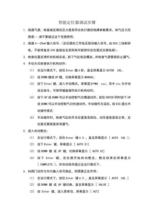
智能定位器调试步骤1.接通气源,检查减压阀后压力是否符合执行器的铭牌参数要求,供气压力范围是—.请不要超过这个范围使用。
2.接通4—20mA输入信号。
(定位器的工作电压取自输入信号,由DCS二线制供电,不能将直流24V直接加至否则有可能损坏定位器定位器电路)。
3.检查位置反馈杆的机械安装,拆下气缸锁定螺丝,并检查气源管路防止漏气。
4.手动方式检查执行机构动作:(1)在运行模式下,按住Enter键6秒,直至屏幕显示AUTOD CAL;(2)按DOWN键或UP键,切换屏幕显示MANUAL;(3)按下Enter键,进入手动模式,屏幕显示*MA xxx,其中xxx为手动设定指令,可使用键盘操作执行机构动作;(4)按下UP或DOWN可以手动控制气功慢速动作,按住ENTER同时按下UP 或DOWN可以手动控制气功快速动作,手动操作无误后,按ESC退出手动操作模式(5)手动操作时,检查气缸的开关位置是否到位,动作速度是否正常,定位器及管路是否有漏气。
5.进入自动整定:(1)在运行模式下,按住Enter 键6 S ,直至屏幕显示 [ AUTO CAL ]。
(2)按下Enter 键,屏幕显示 [ AUTO 01](3)按DOWN 键或 UP 键,切换屏幕显示 [ AUTO 02](4)按下Enter 键,定位器开始自动整定,整定结束后屏幕显示[ COMPLETE ],并自动保存退出至运行模式下。
6.如阀门动作方向与输入信号相反,则需要正反作用:(1)在运行模式下,按住Enter 键6 S ,直至屏幕显示 [ AUTO CAL ](2)按DOWN 键或 UP 键切换,直至屏幕显示 [ VALVE ](3)按 Enter 键,进入菜单项,屏幕显示 [ ACT](4)按Enter 键,屏幕显示 [*ACT ](5)按DOWN 键或 UP 键切换正反作用,并按 Enter 键确认保存,(屏幕显示为正作用 [+ACT RA ] 或反作用[+ACT DA ])7.如定位器屏幕显示与风门开度相反,则需要切换正反开度显示:(1)在运行模式下,按住Enter 键6 S ,直至屏幕显示 [ AUTO CAL ] (2)按DOWN 键或 UP 键切换,直至屏幕显示 [ VAEW ](3)按 Enter 键,进入菜单项,屏幕显示 [ YT 2500L ] 或 [ YT 2500R ](4)按DOWN 键或 UP 键切换,直至屏幕显示 [ VW ](5)按DOWN 键,屏幕显示 [* VW ](6)按DOWN 键或 UP 键切换正反方向开度显示,并按 Enter 键确认保存,(屏幕显示为正作用 [+ VW NOR ] 正方向显示或反方向显示[+ VWREV ])智能定位器程序功能图解1.功能模式:运行模式:即定位器远方操作模式,定位器接受远方操作信号来控制气功动作,并在屏幕上显示RUN。
西门子智能定位器调试说明
西门子智能定位器调试说明大家好,今天我要给大家讲解一下如何调试西门子智能定位器。
我们要明确一点,这个定位器可不一般,它可是高科技产品,有了它,我们的工作生活就会变得更加便捷。
那么,让我们一起来看看如何让这个神奇的定位器发挥出它的最大功效吧!1. 准备工作在开始调试之前,我们需要做好一些准备工作。
确保定位器的电源已经接通,并且电压稳定。
我们需要了解定位器的使用说明书,这样才能更好地进行调试。
我们需要一台电脑,因为我们将通过电脑来控制和查看定位器的状态。
2. 连接定位器接下来,我们需要将定位器与电脑进行连接。
用USB线将定位器的USB接口与电脑的USB接口相连。
然后,打开电脑,进入设备管理器,查看是否能够识别到定位器。
如果能够识别到,那么恭喜你,第一步已经成功完成!3. 下载驱动程序为了能够更方便地控制和管理定位器,我们需要下载安装一款名为“西门子定位器助手”的软件。
这款软件可以帮助我们实时查看定位器的位置信息,以及对定位器进行一些基本的操作。
下载并安装好软件之后,我们就可以开始进行调试了。
4. 查看定位器状态现在,我们已经成功地将定位器与电脑连接在一起,并且安装好了相关软件。
接下来,我们需要查看定位器的状态。
在电脑上打开“西门子定位器助手”,选择“连接设备”,然后选择我们刚刚连接好的定位器。
此时,我们就可以看到定位器的实时位置信息了。
如果一切正常,那么恭喜你,第二步也已经成功完成!5. 调试定位器在确认定位器状态正常之后,我们就可以开始对定位器进行一些基本的调试了。
我们可以尝试改变定位器的移动方向,看看是否能够准确地显示出新的位置信息。
我们还可以调整定位器的灵敏度,以便更好地适应不同的环境和场景。
这些调试操作都需要在电脑上进行,非常简单方便。
6. 保存设置在完成所有的调试操作之后,我们需要将这些设置保存下来,以便下次使用时能够直接调用。
在“西门子定位器助手”中,选择“保存设置”,然后按照提示输入相关信息即可。
定位器操作规程
定位器操作规程1. 引言定位器是一种常用于定位和导航目标位置的工具。
本文档旨在描述定位器的操作规程,帮助用户正确使用定位器,提高工作效率。
2. 术语定义•定位器:一种用于确定目标位置的工具。
•目标位置:用户期望定位器指示的位置。
•操作人员:使用定位器的个人或团体。
•定位误差:定位器测量结果与实际目标位置之间的差距。
3. 安全注意事项在操作定位器之前,请确保遵守以下安全注意事项:•熟悉并遵守定位器的操作手册和使用指南。
•使用合适的个人防护装备,如手套和护目镜。
•在使用定位器时保持注意力集中,避免分心或操作过程中的随意行为。
•遵守现场安全规定,确保周围环境安全。
4. 操作步骤步骤1:准备工作在开始操作定位器之前,进行以下准备工作:1.确保定位器电源正常并已充电。
2.检查定位器的各个部件是否完好无损。
3.将定位器放置在稳定的平面上,并确保其能够自由移动。
步骤2:选择目标位置通过以下步骤选择目标位置:1.使用定位器的显示屏或按钮选择目标位置模式。
2.根据实际需求输入或选择目标位置的相关信息,如坐标、距离或方向等。
步骤3:启动定位器按照以下步骤启动定位器:1.按下定位器的启动按钮或开关,使定位器开始工作。
2.确保定位器的各个部件运作正常,如传感器、指示灯等。
步骤4:定位目标位置通过以下步骤定位目标位置:1.按照定位器的指示,移动定位器并接近目标位置。
2.观察定位器的显示屏或指示灯,根据指示调整移动方向和速度。
3.靠近目标位置时,适当减速并小心调整位置,以消除定位误差。
4.当定位器指示目标位置时,确认位置准确性并停止移动。
步骤5:记录测量结果在定位目标位置后,进行以下记录工作:1.使用定位器的记录功能,将测量结果保存或导出。
2.在相关文件或系统中记录测量结果,并添加必要的标识或注释。
5. 故障排除在操作定位器过程中,可能会遇到一些故障或问题。
以下是常见故障的排除方法:1.如果定位器无法正常启动,请检查电池或电源连接是否良好,并尝试重新启动。
PMD_FMD智能压力变送器调试方法
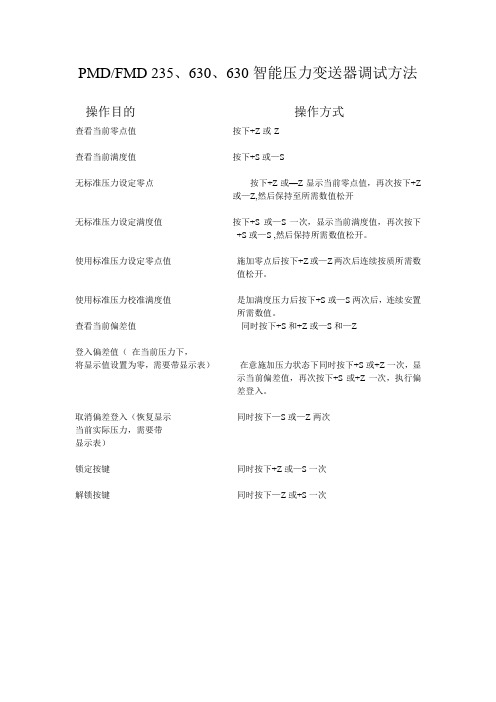
PMD/FMD 235、630、630智能压力变送器调试方法
操作目的操作方式
查看当前零点值按下+Z或-Z
查看当前满度值按下+S或—S
无标准压力设定零点按下+Z或—Z显示当前零点值,再次按下+Z
或—Z,然后保持至所需数值松开
无标准压力设定满度值按下+S或—S一次,显示当前满度值,再次按下
+S或—S ,然后保持所需数值松开。
使用标准压力设定零点值施加零点后按下+Z或—Z两次后连续按质所需数
值松开。
使用标准压力校准满度值是加满度压力后按下+S或—S两次后,连续安置
所需数值。
查看当前偏差值同时按下+S和+Z或—S和—Z
登入偏差值(在当前压力下,
将显示值设置为零,需要带显示表)在意施加压力状态下同时按下+S或+Z一次,显
示当前偏差值,再次按下+S或+Z一次,执行偏
差登入。
取消偏差登入(恢复显示同时按下—S或—Z两次
当前实际压力,需要带
显示表)
锁定按键同时按下+Z或—S一次
解锁按键同时按下—Z或+S一次。
福斯定位器配置指南
福斯定位器配置指南福斯(FLOWSERVE)阀门定位器调试方法(锦菲特I3599429OO2)[Q-Q,6696 22933]flowserve阀门、Flowserve 3400IQ定位器、LOGIX500、LOGIX510、LOGIX520、D3系列P-5 气动定位器电动气动数字- 通用,IS 和EXHART、Profibus、Foundation 现场总线反馈机组、限位开关比如PP5XX-HPGU-23K01-PV9DA-3ZPMV P-1700 系列阀门专为腐蚀或高温环境应用设计,其所有外部零件均由不锈钢制造而成。
P-1700 和1720 型阀门的内部零件采用不锈钢制造,而P-1710 和P-1730 型阀门的内部零件则采用铝制。
P-1720 和P-1730 型阀门具有超高的空气传送能力。
P-1700 系列阀门专为双向操作应用设计,不过也可通过旋动一个阀座轻松实现单向操作。
不锈钢磁场外壳内的PMV I/P 转换器很容易安装在P-1700 系列阀门上。
P-1500 P-1520P-1700 P-1720P-1710 P-1730Digital具有PID 控制的2000 数字定位器品牌Logix说明福斯Logix 2000 是一款具有板载PID 控制的数字定位器。
通信方式为4-20mA 或Modbus。
阀门上安装的PID 控制器每秒更新阀杆位置16 次,从而减少了控制系统延迟。
Logix3200IQ 数字定位器3200IQ-10-D6-M-04-40-0G-0F3200IQ-10-D6-M-04-40-0G-00品牌Logix说明福斯Logix 3200IQ 数字HART? 定位器使用先进的piezo 技术提供一流的性能和可靠性。
通过使用本地按钮、HART 手持设备和SoftTools软件可轻松配置Logix 3200IQ。
LOGIX 3201IQ定位器P/N:215809.999.000,SN:4107028LOGIX 3202IQ定位器P/N:221734.999.000,SN:4907010LOGIX 3203IQ定位器P/N:216428.999.000,SN:610727定位器P/N:215809.999.000,SN:55070043400IQ Digital Positioner品牌Logix说明The Flowserve Logix 3400 Series digital Foundation? Fieldbuspositioner utilizes state-of-the-art piezo technology to provide…500 数字定位器品牌Logix说明福斯Logix 500 数字定位器是下一代本质安全型Logix 500 系列的代表。
定位器的操作方法 -回复
定位器的操作方法-回复人们对于定位器的需求越来越大,尤其是在找寻遗失物品或者追踪物品位置的时候。
定位器可以快速准确地告诉我们物品的具体位置,帮助我们迅速找到丢失的物品。
那么,定位器的操作方法是怎样的呢?首先,首先我们要确保定位器的电量充足。
毕竟,没有电量的设备是无法工作的。
我们应该根据定位器的说明书,找到充电方式,并按照说明书的提示进行充电。
在充电过程中,我们可以先阅读一下定位器的使用说明书,了解操作方法和注意事项。
接下来,我们需要将定位器与我们要追踪的物品相连。
定位器通常有不同的附件或者功能,如钥匙链、贴纸等等。
我们可以选择适合我们物品的附件或者功能,将定位器固定在物品上,比如钥匙、行李箱、手机等。
完成这些准备工作后,我们正式开始使用定位器。
定位器通常会伴随着一个APP或者电脑软件,在使用之前我们需要先下载并安装这个软件。
根据说明书的指示,打开软件并登录账号。
如果还没有账号,我们需要进行注册。
注册完成后,我们需要将定位器与软件绑定。
通常,通过扫描定位器上的二维码或者输入定位器的序列号,我们就可以将定位器与软件绑定。
绑定完成后,我们可以开始使用定位器的功能了。
打开软件,可以看到定位器的相关信息,如电量、信号强度等等。
如果我们要寻找丢失的物品,我们可以点击寻找按钮,定位器将会发出蜂鸣声或者闪烁指示灯,帮助我们找到物品。
有些定位器甚至配备有地图导航功能,我们可以通过手机或者电脑软件上的地图,实时查看物品的具体位置。
除了寻找功能,定位器还具备远程报警功能。
如果我们离开某个物品一定距离,定位器将会自动报警。
具体的报警方式会因不同的定位器而有所不同,有些会通过手机APP发送警报信息,有些会通过设备本身发出声音或者震动。
这对于我们防止物品被盗或者丢失是非常有帮助的。
此外,定位器还可以进行历史轨迹回放。
我们可以通过软件查看物品的历史移动路径,了解物品曾经所处的位置。
这对于做一些统计或者分析是非常有用的。
最后,当我们找到了丢失的物品或者完成了定位器的使用目的后,我们应该记得关闭定位器或者停止追踪功能,以免浪费电量或者造成不必要的干扰。
定位器调校方法
梅索尼兰调节阀调试方法:将HART375 手操器连到阀门定位器上后,启动HART375 进入MANUAL 模式→Calibration Menu→Tuning→AutoTune,然后定位器开始自检,待自检完毕后,退出Calibration Menu 模式,进入Normal 模式即可。
下面举出几个具体列子:1. 阀门反馈不正常解决方法:启动HART→进入MANUAL 模式→Calibration Menu→Range→Autostops 运行结束后,退出Calibration Menu 模式,进入Normal 模式即可2. 阀门波动大解决方法:启动HART→进入MANUAL 模式→Calibration Menu→Tuning→PID coefficient 选2 次OK→选择一次entet→将I 值相应放大→选择enter7 次后再选择一次OK,修改I 参数完成.运行结束后,退出Calibration Menu 模式,进入Normal 模式即可3. 零位或满位偏差大解决方法:启动HART→进入MANUAL 模式→Calibration Menu→Range→Autostops 运行结束后,退出Calibration Menu 模式,进入Normal 模式即可4.阀门不动作从以下几个方面检查: 1) 检查阀门是否送电,是否有气源和指令线是否有问题2) 有手动装置的阀门检查是否阀门在手动位置3)是否用HART375 调试时打到MANUAL 模式,调试结束后未返回Normal 模式FISHER 调节阀调试方法:在调试之前首先确认阀门的Travel值(阀体上的标牌上有标注,比如1/4,3/4 等) ,且使阀门处于初始状态(即全开或全关,根据阀门是气开阀还是气关阀而定) ,然后将定位器外壳螺丝松开, 打开外壳取出里面的黑色小圆棒将小圆棒穿过定位器与阀杆连接部分后卡在定位器边上的小孔上,将连接部分可移动的杆放在与阀门Travel 值对应的位置上固定即可,将信号源和HART连接到定位器后,启动HART,选择0(当位置反馈装置是Tri-Loop 时) 或定位器的型号(4210 型位置反馈装置)→Setup&Diag→Detailed Setup→Mode→Instrument Mode→Out of service(注意:此项再调试完毕后要返回到In service)→返回Basic Setup→ Auto Setup→Auto Calib Travel→Manual(注意:此处有一个选择交叉点的过程,当在交叉点的时候,要求阀杆与定位器连接部分标有Travel 值的空档处处在水平位置)→Analog→In serviceFISHER 调节阀位置反馈装置调试方法:1. 就地安装的4210型位置反馈装置,首先用信号源加12mA 的信号, 使阀门开度在50%, 用万用表量电路板上的TP3 和TP4 的电压,要求当位置反馈装置与阀杆连接处的横档在水平位置时,二者之间的电压是1.25V,若不是则进行调整.然后用信号源加4mA信号,量TP1 和TP2之间的电流,看反馈是4mA 还是20mA,如果是一个接近4mA的数就调整调零旋钮,使反馈的信号为4mA;如果是一个接近20mA的数就调整量程旋钮使反馈的信号为20mA.同样的方法来确定当给出的信号是20mA 时反馈的信号,如此多次直至确定零位和量程2. 电子间机柜内安装的Tri-Loop 位置反馈装置将HART连接到Tri-Loop位置反馈装置的通讯连接端口上,启动HART,进入Utility→ Configure HART Application→Polling→Digital Poll,然后退出到主画面选择Online→选择定位器的型号→Setup&Diag→Detail Setup→Mode→Burst→BurstEnable→Enable→返回Burst 画面选择Burst Command→HART Univ Cmd 3→返回到主画面后选择Online→"1"(指Trip-Loop)→Device Setup→BasicSetup→Configure Channels→Configure CH1→将Burst Variable 的类型改为"QV"Units 设为,"%"LRV 设为,"0",URV 设为"100",CH1 Enabled 设为"YES"然后保存即可.瑞基调门调试方法:瑞基调门调试是使用遥控器来调试的, 使用遥控器对中液晶显示屏按"┙"输入口令"000"进入一级设定菜单, 在一级设定菜单里主要是确定阀门的开关限位, 此时可手动将阀门打到全开(或全关)位置,然后使用遥控器按"↓"选择"打开限位"(或关闭限位) ,按"┙"进入,然后确定保存即可.之后退回主菜单,进入二级设定菜单,在二级菜单下主要是设定输入信号的量程,选择进入模拟信号量程项,选择20mA;然后将阀门打到就地控制状态用信号源加一个4mA 的信号,设定为低限阀位,加20mA 信号设为高限阀位保存即可! 此外可以使用遥控器来调整阀门的力矩,开关方向,保护方式等,具体情况根据显示屏显示选项操作即可西门子定位器调试方法:1.用定位器显示窗口下方的'+'和'-'两个按键, 使执行机构运动, 看整个机构能否自由走满行程.2.让执行器运动到行程的中间位置(直行程的反馈杆处于水平位置) ,就可以进行初始化了. 注:当你按住其中一个键的同时再按另一个键可以加快执行机构的动作.3.按功能键(小手形)5 秒后就可以进行参数设置.4.SIEMENS 定位器共有36 组参数, 可以根据现场的实际情况进行设置. 用'+'和'-' 键可以在一组参数中进行选择, 选择完后可以按一下功能键进入第二组参数的设置, 若上一个参数设置有误,可以按功能键同时按'-'键,回到上一个参数再进行设置.5.在这些参数中有几个是经常用到的. 1YFCT (执行器类型) :直行程选WAY,角行程选TURN. 2YAGL (额定反馈角度) :一般情况下,直行程设置成33,角行程90. 7SDIR: 给定方向上升RISE,给定方向下降FALL 38YDIR (操作变量方向显示) :上升RISE,下降FALL 同时改变SDIR 和YDIR 这两组参数可改变执行器动作方向. 55PRST 预设置(工厂设置) :当重新调试时,先进入55 项,长按+键 5 秒,直到显示ocay,说明已经恢复到工厂设置5.开始初始化时执行器必须处于行程的中间位置.6.参数设置完毕后用功能键切换到第四个参数,显示为'4.INIT',按住'+'键约5 秒定位器就自动进行初始化了.7.初始化一共分为5 步. 1)决定动作方向. 2)检查执行机构行程和零点. 3)确定执行机构上下动作时间. 4)确定最小的定位增量. 5)最佳的瞬时响应.8.当初始化完成时屏幕上显示"FINISH"按一下功能键显示"4.INIT".9.按功能键5 秒后,当屏幕显示有变化时松手,此时定位器处于手动模式,再按一下功能键定位器处于自动模式.10.初始化结束后定位器即进入正常工作状态.。
西门子定位器调整步骤概要
西门子定位器调整步骤概要
西门子定位器调整步骤概要
调整西门子定位器步骤
1、把定位器在底部黄色推板推到上面,在上部能看到即可。
2、给定输入信号12mA。
3、用手按“+”或“-”让执行器行到中间(45°位置(气缸
一半。
4、按功能键(手出现“2 90°”. 按功能键(手出现“4 no”,
按“+”5秒钟,自动调整。
如出现“”,旋转下面调整
凸轮,“右转”直到出现“”。
再按“+”又出现自动调
整,直到出现“FINSN”,按功能键(手一下,出现“4”, 按
功能键(手5秒钟出现“C5”手动,再按功能键(手,以下
自动。
5、如果发现信号给定反作用,“7”和“38”倒一下。
按功能键(手5秒钟出现“1”,继续按到“7”,再按“+”或“-”变换。
再接着按功能键(手到“38”,按“+”或“-”变换。
按功能
键(手5秒出现“C5”,再按功能键(手变为自动。
6、“34”是灵敏度调节。
7、如需要回到原始状态,按“手”5秒钟,出现“1”接着按“手”,
直到出现“55”,再按“+”5秒钟直到有变化即可。
(EURN角行程(WRY直行程。
PMV D3定位器使用入门
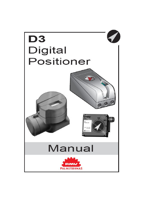
PMV D3数字阀门定位器使用手册1. 简介PMV D3是一种数字式阀门定位器,主要用于阀门调节。
单作用、双作用执行器上均可安装,也适用于直行程和角行程两种型式。
它还可以选装反馈、限位开关、压力表等部件。
这些部件是在发货之前就装配好的,交货后也可定制。
反馈和限位开关部件包括4-20mA反馈和下列三者之一——双机械触点、双簧片开关、双电感式传感器(DIN 19234)。
安全使用的特殊设计PMV D3I(本安型)的封装由铝组成,应避免应用中发生外界物体对其的任何碰撞或摩擦。
2. 存储(略)3.设计PMV D3定位器包括:·电路板,附有微处理器、HART模块、Profibus、Foundation Fieldbus(基金会现场总线)、显示,等等;·阀块;·带电位差计的位置反馈;·电气连接的密封隔离。
按钮和显示屏位于铝盖下方,由O型环密封。
下图为移去盖子后的PMV D3。
4. 不同型号的PMV D3PMV D3通用型PMV D3数字定位器极易使用,它含有五个按钮的用户接口和LCD显示屏。
通信方式有4-20mAHART、基金会现场总线和Profibus PA。
全部PMV D3定位均能可含有反馈、Fail Freeze(失效保护,当掉电时保持失效前的阀位)、270度旋转(对于外部行程)和压力计。
PMV D3 防爆型PMV D3数字定位器还可加上防爆外壳。
防爆型具备所有通用型的性能特点,也含有五个按钮的用户接口和LCD显示屏,也可以通过HART、基金会现场总线和Profibus进行通信。
但是防爆型增加了压力计接口和就地图形化LCD显示器。
ATEX:EEx d ⅡB + h2T6(Ta+65℃),T5(Ta+80℃) Ⅱ 2GDPMV D3 本安型易爆炸危险场所可使用本安型PMV D3数字定位器。
本安型具备前两种型号定位器的所有性能特点。
ATEX:EEx ia ⅡC T4 Ta=-30……80℃Ⅱ 1GDCSA, FM Class I Div.1 Grps B, C, D, Class ⅡDiv.1 Grps E, F, G, T6, T5.PMV D3 遥控安装该型适合安装于一些特殊应用场合,如振动、高(或低)温腐蚀环境、难以接近或进入场合等。
定位器操作说明
(三)注意事项
• 压缩空气气源要保持洁净,干燥 • 电气接口接线后密封可靠,无松动 • 定位器调试完成后,外壳盖紧 • 如果个别位置无法排除外界杂质进入定位
内部,可参考做如下图处理
谢谢!
A. 基础菜单与完整菜单之间的切换 基础菜单(basic menu)只有 5 项,完整菜单 (full menu)有 9 项。在 shift menu 里面完 成基础与完整菜单之间的切换。
B. 切换中文菜单 出厂默认是英文菜单,可以在设定(setup) 里面找到外观(Appearance),再找到语言 (language),从中选择中文(chinese)。 按 OK 键确认选择。界面瞬时换成中文。
自动调试
• 首先切换到离线状态,此时屏幕左上角有竖条光标在闪烁,
表示定位器处于已处于离线状态,此时不接受 DCS 信号 控制。同时按住上,下两键 5 秒钟,此时三个灯交替闪烁, 松手,此时已开始自动校验。校验结束会停留在黄灯闪烁 (阀门处于开或者关的位置)或者绿灯闪烁(阀门处于中 间位置)。
• 或者进入校验(calibrate)菜单,选择自动校验(
• 方法如下: • 依次输入4,8,12,16,20mA,检查阀门位置是否一
一对应,连续按3次黄色按键,此时正反作用已切 换,重新输入4,8,12,16,20mA检验。
恢复出厂设置
• 在断电(也就是不接入信号)情况下,按 住黄色按钮,然后按照正负极接入信号 (直到三个灯被点亮,然后黄-红交替闪 烁),此时松开按钮,这时就完成了恢复 出厂设置。
4-20mA 输出信号校验
• 进入校验(calibrate)菜单,选择专业校验 (expert cal),进入传送(transm)。校 验传送低值(transm low)调整到 4mA 按 OK 键确认;校验传送高值(transm hi)调 整到 20mA 按 OK键确认。前提是需要给输 入接线柱 4mA 供电,同时输出接线柱串联 24V 电源和万用表测量输出。
常见十二种定位器,调试步骤
常见十二种定位器,调试步骤阀门定位器是控制阀的主要附件,它将阀杆位移信号作为输入的反馈测量信号,以控制器输出信号作为设定信号,进行比较,当两者有偏差时,改变其到执行机构的输出信号,使执行机构动作,建立了阀杆位移量与控制器输出信号之间的一一对应关系。
本文重点讲解常见定位器调试步骤,帮助仪表人轻松掌握各类定位器。
一阀门定位器的原理、作用阀门定位器是控制阀的主要附件。
它将阀杆位移信号作为输入的反馈测量信号,以控制器输出信号作为设定信号,进行比较,当两者有偏差时,改变其到执行机构的输出信号,使执行机构动作,建立了阀杆位移量与控制器输出信号之间的一一对应关系。
因此,阀门定位器组成以阀杆位移为测量信号,以控制器输出为设定信号的反馈控制系统。
该控制系统的操纵变量是阀门定位器去执行机构的输出信号。
(1)用于对调节质量要求高的重要调节系统,以提高调节阀的定位精确及可靠性。
(2)用于阀门两端压差大(△p>1MPa)的场合。
通过提高气源压力增大执行机构的输出力,以克服液体对阀芯产生的不平衡力,减小行程误差。
(3)当被调介质为高温、高压、低温、有毒、易燃、易爆时,为了防止对外泄漏,往往将填料压得很紧,因此阀杆与填料间的摩擦力较大,此时用定位器可克服时滞。
(4)被调介质为粘性流体或含有固体悬浮物时,用定位器可以克服介质对阀杆移动的阻力。
(5)用于大口径(Dg>100mm)的调节阀,以增大执行机构的输出推力。
(6)当调节器与执行器距离在60m以上时,用定位器可克服控制信号的传递滞后,改善阀门的动作反应速度。
(7)用来改善调节阀的流量特性。
(8)一个调节器控制两个执行器实行分程控制时,可用两个定位器,分别接受低输入信号和高输入信号,则一个执行器低程动作,另一个高程动作,即构成了分程调节。
二阀门定位器的分类1、阀门定位器按输入信号分为气动阀门定位器、电-气阀门定位器和智能阀门定位器。
(1)气动阀门定位器的输入信号是标准气信号,例如,20~100kPa气信号,其输出信号也是标准的气信号。
pmvd3定位器说明pdf
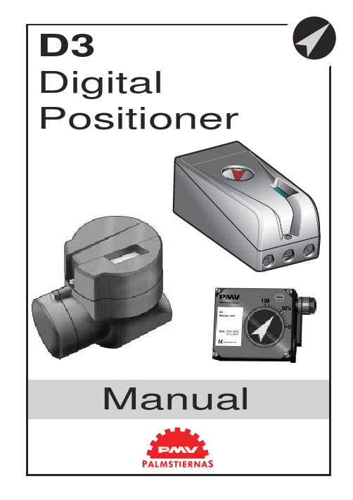
Positioner2 Safety instruction (3)2. Storage (4)General (4)Storage indoors (4)Storage outdoors or for a longer period (4)Storage in a warm place (4)3. Design (5)4. Variants (6)5. Function (7)Double action function (7)Single action function (7)6. Installation (8)Air supply requirements (8)Mounting (9)Connections (10)Air (10)Electrical connection (10)Dimensions (10)Single action positioner (Direct function) (11)Actuator with closing spring (11)Actuator with opening spring (11)Double action positioner (Direct function) (11)Double action actuator (11)Electrical connections (12)7. Control (14)Menus and pushbuttons (14)Other functions (14)Menu indicator (15)Menus (15)Changing parameter values (15)Menu system (16)First start (17)8. Maintenance/service (37)Disassembling PMV D3 (37)Silencer (39)Spindle adapter (39)Potentiometer (40)Transmitter boards (41)Disassembling PMV D3 Ex (44)Filter change (45)Converting for remote control (46)9. Trouble shooting (47)10. Technical data (48)Certificates (48)11. Spare parts (56)3The PMV D3 is a digital positioner de-signed primarily for controlling adjustable valves.The positioner can be used with single or double action actuators with either rotary or linear movement.The D3 can be equipped with modules for feedback, limit switches, and a pressureThe modules can be factory assembled before delivery or fitted later.The modules for feedback and limit switches can contain the following:Feedback 4-20 mA and one of the following functions:- Two mechanical contacts - Two reed switchesGeneralThe PMV positioner is a precision in-strument. Therefore it is essential that it is handled and stored in the right way. Always follow the instructions below!N.B.As soon as the positioner is connected and started, internal air leakage will provide protection against corrosion and prevent the ingress of moisture. For this reason, the air supply pressure should always be kept on.Storage indoorsStore the positioner in its original packaging. The storage environment must be clean, dry, and cool (15 to 26°C, 59 to 79°F..Storage outdoors or for a longer periodIf the positioner must be stored outdoors, it is important that all the cover screws are tightened and that all connections are properly sealed. The unit should be packed with a desiccant (silica gel) in a plastic bag or similar, covered with plastic, and not exposed to sunlight, rain, or snow.This is also applicable for long-term storage (more than 1 month) and for long transport by sea.Storage in a warm placeWhen the positioner is stored in a warm place with a high relative humidity and is subjected to daily temperature variations, the air inside the unit will expand and contract.This means that air from outside the unit may be drawn into the positioner. Depending on the temperature variations, relative humidity, and other factors, condensation and corrosion can occur inside the unit, which in turn can give rise to functional disorders or a failure.45The D3 positioner contains:• Electronic board with microprocessor, HART modem, display, etc.• Valve block• Positional feedback with potentiometer • Sealed compartment for electrical connectionsThe push buttons and display are accessible underneath the aluminium cover, which is sealed with an O-ring.The figure shows the D3 with the cover removed.Double action functionThe control signal and the feedback potentiometer position are converted to di-gital signals that are processed with a PID algorithm in the microprocessor. This prov-ides control signals to the two piezo-valves.The two piezo-valves are closed in the schematic diagram above and have no effect on the valves A and D. Air from the pressure regulator is lead through the open valve A to the valve B, which opens. The supply pressure can now pass through valve B to the actuator via H. The actuator then moves in the direction of the arrow. At the same time, air from valve A keeps valve C open and allows venting of the actuator.When both the piezo-valves open, valve A closes but valve D opens and controls valves E and F to that the actuator moves in a direction opposite to the arrow. When only piezo-valve 1 is open, the actuator is stationary.Single action functionValve B is used for the supply air and valve F for venting.78TubingUse tubes with an inner diameter of mi-nimum 6 mm (1/4”).Air supply requirementsMax. air supply pressure, see the section Technical Data, Section 10.The air supply must be free from moisture, water, oil, and particles.The air must come from a refrigeration dried supply or be treated in such a way that its dew point is at least 10°C (18°F) below the lowest expected ambient temperature.To ensure a stable and problem-free air supply, we recommend the installation of a filter/pressure regulator <40µ as close to the positioner as possible.Before the air supply is connected to the positioner, we recommend the hose is opened freely for 2 to 3 minutes to allow any con-tamination to be blown out. Direct the air jet into a large paper bag to trap any water, oil,or other foreign materials. If this indicates that the air system is contaminated, it should be properly cleaned.Poor air supplies are the main source of problems in pneumatic systems.Mounting910C– S C+For data for air and electrical connections, see section Technical Data on page 48.ConnectionsAir:Port S Supply air, 2-7 bar Port C+Connection to actuator Port C-Connection to actuator (only for double action)Electrical connection See page 12, 13.DimensionsAir connections:1/4" NPT alt. G 1/4"Electrical connection:M20 x 1.5 alt. NPT 1/2"Loctite 577 or equivalent is recommendedas a sealant. Must be plugged when converting to11Single action positioner (Direct function)Actuator with closing springWhen the control signal increases, the pressure C+ to the actuator is increased. The valve spindle moves upward and rotates the positioner spindle counter-clockwise. When the control signal drops to zero, C+ is vented and the valve closes.Actuator with opening springWhen the control signal increases, the pressure C+ to the actuator is reduced. The springs press the valve spindle upward and the positioner spindle rotates counter-clockwise. When the control signal drops to zero, C+ is vented and the valve opens.Double action positioner (Direct function)Double action actuatorWhen the control signal increases, the pressure C+ to the actuator is increased. The valve spindle is pressed upward and rotates the positioner spindle counter-clockwise.When the control signal is reduced, the pressure C- to the actuator increases and the valve spindle is pressed downward. If the control signal disappears, the pressure goes to C-, C+ vents, and the valve closes.D3 Electrical connectionsThe diagrams show the terminal blocksin D3 and D3 Ex.Remote unitThe remote unit shall be connected between terminals3, 4 and 5 in the D3 and 3,4 and5 in the remote unit. Use a shielded cable and ground it in the D3 only. Max recommended distance between D3 and remote unit: 5 m.13D3 ExThe terminal block (below) for the posi-tioner is accessible when the terminal cover is removed, see Section 8.14Menus and pushbuttonsThe positioner is controlled using the five pushbuttons and the display, which are accessible when the aluminium cover is removed.For normal functioning, the display shows the current value. Press the ESC button for two seconds to display the main menu.Use the pushbuttons to browseThe main menu is divided up into a basic menu and a full menu, see page 16.Other functionsESCExit the menu without making any changes (as long as any changes have not been confirmed with OK).FUNCTo select function and change parameters.OKTo confirm selection or change of para-meters.MENU INDICATORDisplays the position of the current menu row in the menu.OUT OF SERVICE MANUALIN SERVICEThe positioner is following the input sig-nal. This is the normal status when the posi-tioner is working.OUT OF SERVICEThe positioner is not following the input signal. Critical parameters can be changed.MANUALThe positioner can be adjusted manually using the pushbuttons. See section ”Man/Auto”, page 21”.UNPROTECTEDMost of the parameters can be changed when the positioner is in the ”Unprotected”position. However, critical parameters are locked when the positioner is in the ”In ser-vice” position.15Menu indicatorFlashing in position Flashing in position Manual Displayed in position MenusTo display the menus you can select:- Basic menu , which means you can browsethrough four different steps- Full menu , which comprises ten steps. Use the Shift Menu to browse through the steps Full Menu can be locked out using a passcode.The main menus are shown on the next page and the sub-menus on the subsequent pages.figure is flashing.A change can be undone by pressing the ESC button, which returns you to the previous menu.16Menu systemThe menus are describedon the following pages.17First startCalibrate in the basic menu is displayed automatically the first time the positioner is connected up, and can be selected from the basic/main menu at any later time.A complete calibration takes about 3minutes and includes end limit calibration,auto-tuning, leak test, and a check on the speed of movement. Start the automatic calibration by selecting Auto-Cal and then answer the questions on the display by pres-sing OK or the respective arrow. The menu is described on the next page.Calibration error messagesIf a fault occurs during calibration, one of the following error messages can be dis-played:Invalid movement/press ESC to abort No movement because the air is incorrectly connected, for example. After the fault is corrected, the calibration sequence must be restarted.Pot unaligned/press ESC to abortThe potentiometer has been set to an il-legal value. The potentiomenter is aligned using the Calibrate - Expert cal - pot Menu.The calibration sequence must be restarted after the fault is corrected.Air leak detected/ESC = abort OK = go onAn air leak has been detected. The calibration sequence should be restarted after the fault is corrected.Increase C- damper/ESC = abort OK to retryIncrease C+ damper/ESC = abort OK to retrySpeed of movement is too fast. Adjust with the damper screws (see page 5). Press OK. Repeat the adjustment and press OK until the speed is correct. If there is an abort,the calibration sequence must be restarted.First start, ProfibusConnect the input signal at pos 1 and 2on the terminal block. See Electrical connections in the manual.In the SETUP/Devicedata/Profibus:change the address from 126 to any number between 1-125.Do never use the same number to more than one unit. Install values in failsafe mode,for communication when loss of signal.Calibrate the unit.GSD files are available at our homepage www.pmv.nu18The contents of the menu are shown on the next page. The various menu texts are described below.Auto-Cal Auto-tuning and calibration of end positionsStart tuneStarts the tuning. Questions/commands are displayed duringand confirm with OK as shown in the chart on the next page.Lose prev value? OK? A warning that the value set previously will be lost (not during the first auto-tuning).Actuator? rotating Select for rotating actuator. Actuator? linear Select for linear actuator. Actuator single act Select for single act.Actuator double act Select for double act. Direction? direct Select for direct function. Direction? reverse Select for reverse function.In service? Press OKCalibration finished. Press OK to start positioner functioning. (If ESC is pressed, the positioner assumes the ”Out of service” position but the calibration is retained).TravelCal Calibration of end positions Start calStart end position calibration.Lose prev value? OK?A warning that the previously set value will be lost.Confirm with OK.The calibration sequence starts.In service? Press OKCalibration finished. Press OK to start positioner functioning.(If ESC is pressed, the positioner assumes the ”Out of service”position but the calibration is retained).Perform Setting gain Normal100% gainPerform 50%, 25%, 12%, L, M, S Possibility to select a lower gain in steps. L, M, S Preset values for L, M, S actuatorsFactory setResets all set values and enters Factory Mode. Should only be used by authorized staff.Note. Original P. I. D. will always be shown in display1920Current values can be read using the Read Menu and some values can be reset.Pos Shows current position Set&pos Set point and position Set&dev Set point and deviation Temp Shows current temperature AuxExternal pot or similarStatistics n cycles(turns)Acc travel Shows accumulatedmovement mean devin %runtimesince last resetExtr temp temperature Histogram PVAlarms Displays tripped alarms21The menu contents are shown in the figures on the right and the various texts are described below:AUT, OK = MANPositioner in automatic mode MAN, OK = AUTPositioner in manual mode In the MANbe changed usingThe push-buttons increase/decrease the value in steps.The value can also be changed in the same way as for the other parameter values, as described on page 15.Other functionsC+ can be fully opened by pressingand then immediately OK simultaneously.C- can be fully opened by pressing and OK simultaneously.clean by pressing simultaneously.When changing between MAN and AUT mode, the OK button must be depressed for 3seconds.The Man/Auto menu is used to change between manual and automatic modes.22up in SETUP menu)..The Shift Menu is used to choose between the basic menu and the full menu.The menu contents are shown in the figures on the right and the various texts are described below:No Full menu selected.YesBasic menu selected.texts are described below: o o servicein service Positioner in service.Critical parameterscannot be changed.When changing betweenIn service and Out of ser-vice, the OK button must be depressed for 3 seconds.2324Actuator Type of actuator Size of actuator Time out Rotating Rotating actuator.Small 10 s LinearLinear actuator.Medium 25 s Large 60 s Texas180 sLever Only for linear actuator.Lever stroke Stroke length to achieve correct display.Level cal Calibration of positions to achieve correct display.Direction Direct Direct function (signal increase opens). Indicator/spindle rotates counter-clockwise. ReverseReverse function.Character Curves that show position as a function of input signal. LinearEqual %See diagram.Quick openSqr rootCustom Create own curve.Cust chr# of point Specify number of points (3, 5, 9,17, or 33)Cust curve Enter values on X and Y axes.Curr range 0%=4.0 mA 100%=20.0 mAPossibility of selecting which input signal values will correspond to 0% and 100% movement respectively. Examples of settings:4 mA = 0%, 12 mA = 100%, 12 mA = 0%, 20 mA = 100%.The Setup Menu is used for various settings .The menu contents are shown in the chart on the next page and the various texts are described below:25Set percentage valuefor desired end posi-tion (e.g. 3%).Set 0%Select In Service.Connect calibrator.Move forward to desiredend position (0%) andpress OK.100%=100.0%Select Out of Service.Set percentage value fordesired end position (e.g.97%).Set 100%Select In Service.Connect calibrator. Moveforward to desired endposition (100%) andpress OK.Trvl ctrl Behaviour at set endpositionSet low Choose between Free (goto mechanical stop),Limit (stop at set endposition), and Cut off (godirectly to mechanicalstop at set end position). Set high Similar to Set low.V alues Select position for Cut offand Limit at therespective end positions. Passcodes Setting passcodes forvarious functionsFull menu Passcode for access tofull menu.Write prot Passcode for removingwrite protect.Expert Passcode for access toExpert menu (TUNING). Fact set Passcode to return todefault values applicablewhen positioner wasdelivered.passcodes. 0 = no passcode required. Appearance On displayLanguage Select menu language. Units Select units.Def. Display Select value(s) to bedisplayed during service.The display reverts tothis value 10 minutesafter any change is made. Start menu Start in Basic menu orFull menu.Contrast Adjust display contrast. Orient Orientation of text ondisplay.Par mode Display of control parameters such as P, I, D orK, Ti, Td. DevicedataHW rewSW rew General parameters. CapabilityHART Menu with HART para-meters. Only amendablewith HART communi-cator. It is possible to readfrom display. ProfibusStatus Indicates present status Device ID Serial number Address1-126T ag Allotted ID Descriptor ID descriptionDate N/AFailsafe V alue = preset posTime = Set time +10sec=time before movementV alve act = failsafe(preset pos) or lastvalue(present pos)Alarm out= On/Off262728Close time Minimum time from fully open to closed.Open time Minimum time from closed to fully open.Deadband Setting deadband. Min. 0.2%.Expert Advanced settings.Togglestep Test tool for checking functions. Overlays a square wave on the set value.K, Ti, Td Setting K, Ti, and Td parameters.Self test Test of processor, potentiometer, etc.LeakageAir leakage detected can be either connections, positioner tubing or actuator.UndoYou can read last 20 changes.The menu contents are shown in the chart on the next page and the various texts are described below:2930Deviation Alarm generated when deviation occurs On/Off Alarm on/off.Distance Allowed distance before alarm is generated.TimeTotal deviation time before alarm is generated.Alarm out Select ON/OFF offers output on terminals 13 and 14.Valve act Behaviour of valve when alarm is generated.Limit 1Alarm above/below a certain level.On/Off Alarm on/off.Minipos Setting of desired min. position.Maxpos Setting of desired max. position. See diagram below!Hysteresis Desired hysteresis.Alarm on Select ON/OFF offers output on terminals 13 and 14.Valve act Behaviour of valve when alarm is generated.Limit 2See Limit 1.The menu contents are shown in the chart on the next page and the various texts are described below:Limit 1, max Hysteresis Limit 2, max HysteresisHysteresis Limit 2, minHysteresis Limit 1, min0%100%Alarm Limit 1 onAlarm Limit 2 onAlarm Limit 1 offAlarm Limit 2 offAlarm Limit 2 onAlarm Limit 1 onAlarm Limit 1 offalarm Limit 2 offT r a v e lSet alarm and hysteresis values3132Pos=aux External potentiometer On/Off Function on/off.Max diff Max. allowed deviation between internal and external potentiometer.Alarm out Select ON/OFF offers output on terminals 13 and 14.Valve act Behaviour of valve when alarm is generated.Aux input External input signal 4-20 mA.On/Off Alarm on/off.Minipos Setting of desired min. position.Maxpos Setting of desired max. position.Hysteresis Desired hysteresis.Valve actBehaviour of valve when alarm is generated.Function similar to Limit 1 and 2.See chart on previous page.33Temp Alarm based on temperatureOn/Off Temperature alarm on/off.Low temp Temperature setting.High temp Temperature setting.Hysteresis Allowed hysteresis.Alarm out Select ON/OFF offers output on terminals 13 and 14.Valve act Behaviour of valve when alarm is generated.Valve actNo action Alarm generated only. Operations not affected.Goto open C+ gives full pressure and valve moves to fullyopen position. Positioner changes to positionManual.Goto close C- gives full pressure and valve moves to fullyclosed position. Positioner changes to positionManual.Manual Valve stays in unchanged position. Positionermoves to position Manual.The menu contents are shown in the chart on the next page and the various texts are described below:The default values that were set on delivery can be reset using the Fact Set menu. Values from calibration and from other settings will then be lost.343536Removing cover and inner cover• Unscrew the screws A and remove the cover.• Pull off the arrow pointer, B.• Unscrew the screws C, pull the inner cover slightly in the direction of the arrow, andremove the cover.38Circuit boards (pcb)work.• Lift off the display pcb.sor pcb.the spacers H.Valve blockTurn off the air and electric powersupply before starting any work.• R elease the connector F from the proces-sor pcb.¥ R emove the four screws I.¥ L ift out the valve blockN.B. Do not disassemble the valve block ¥ When installing the valve block Ñ torque the f our screws to 1,4 Nm and sealwith L ocktite 222.SilencerA silencer, L (option) can be mounted under the plate M on the D3. Contact PMV. Spindle adapterThe spindle adapter can be changed to suit the actuator in question, see page 9.M L40Transmitter boardsThe equipment for transmitter feedback consists of a circuit board A, cam assembly B and screws.The circuit board exists in four:- with mecanical switches, SPDT - with namur sensors, DIN 19234- with proximity switches- with feedback transmitter onlyPotentiometer90° and 270° spring loaded potentiometer The spring-loaded potentiometer K can be removed from the gearwheel for calibration or replacement.If the potentiometer is replaced or the set-ting is changed, it must be calibrated.• Select the menu Calibrate - Expert - Cal pot. The display shows Set gear (1).• Turn the spindle shaft (2) cw to end posi-tion and press OK. Turn ccw to the end and press OK.• Unmesh the potentiometer (3) and turn it according to display until OK is shown. Press OK.Transmitter board installationCaution! Turn off the power and air supply starting the installation.Important for D3 Intrinsically safe units:Transmitter boards NOT for on site mounting by customer. FM, CSA and ATEX certificate only valid when trans-mitter board is mounted by manufacturer.• Remove the cover, indicator and inner cover according to the description on page 37.• Check that both spacers C are installed.• Carefully mount the circuit board in its position. The pins D should fit in the connector and the positioners motherboard.Make sure that the feed back PC board is properly connected.• Secure the circuit board with the enclosed screws E .• Install the cam asssembly B on the shaft and push it down to its position. If the board has microswitches, be careful not to damage the levers.• Tighten the screws F, on the cam assembly. Do not tighten the screws to hard. The cams should be able to move in relation to each other.• Install the inner cover with the two screws, G.• Connect the wiring for the transmitter feed-back on the terminal block, according to the drawing on next page.• Adjust the position where the switches/ sensors should be affected, by turning the cams with a screwdriver.• Tighten the cam assembly screws F when the cams are correctly adjusted.• Install the indicator and cover.To calibrate the feedback transmitter, see drawing on next page.• Release the wide cable from the connector J on the terminal board.• Loosen the three screws K.• Remove the circuit board package L, con-sisting of terminal and processor board.• Remove he four screws M and lift the block N.Filter change, D3 and D3 ExTurn off the compressed airsupply before starting any work.Otherwise the filter can beuncontrollably blown out of thepositioner by the air pressure,which can be dangerous.• Remove the filter cap using a coin of suitable size.Note! Do not use a screwdriver. The fil-ter cap might crack and cause air leakage.Fault symptomChange in input signal to positioner does not affect actuator position.Change in input signal to positioner ma-kes actuator move to its end position. Inaccurate regulation.Slow movements, unstable regulation.Action• Check air supply pressure, air cleanliness, and connection between po-sitioner and actuator.• Check input signal to positioner.• Check mounting and connections of po-sitioner and actuator.•Check input signal.•Check mounting and connections of po-sitioner and actuator.• Implement auto-tuning. Check for any leaks.• Uneven air supply pressure.• Uneven input signal.• Wrong size of actuator being used.• High friction in actuator/valve package.• Excess play in actuator/valve package.• Excess play in mounting of positioner on actuator.• Dirty/humid supply air.• Implement auto-tuning.• Adjust the pressure adjusting screws.• Increase the deadband (Tuning menu).• Adjust Performance (Calibrate menu).Rotation angle min. 30° max 100°Stroke 5 - 130 mm (0.2” to 5.1”)Input signal 4 - 20 mAAir supply 2 - 7 bar (30 - 87 psi) Free from oil, waterand moisture. Filtered to min. 30 micron Air delivery400 nl/min (13.8 scfm)Air consumption<0.3 nl/min (0.01 scfm)Air connections1/4” G or NPTCable entry 3 x M20 or 1/ 2” NPTElectrical connections Screw terminals 2.5 mm2 /AWG14 Linearity<1%Repeatability<0.5%Hysteresis<0.4%Dead band0.2-10% adjustableDisplay Graphic, view area 15 x 41mm (0.6 x 1.6”) UI 5 push buttonsProcessor16 bit, M 16CCE directives93/68EEC, 89/336/EEC, 92 /31/EEC EMC EN 50 081-2, EN 50 082-2V oltage drop<10.1VVibrations<1% up to 10 g at frequency 10 - 500 Hz Enclosure IP66/NEMA 4XMaterial Die-cast aluminium, A2/A4 fasteners Surface treatment Powder epoxyTemperatur range–30 to +80°C (–22 to 176° F)Weight D3X, 1.4 kg (3 lbs). D3E, 3 kg (6.6 lbs) Alarm output Transistor Ri 1KΩAlarm Supply V oltage8 - 28 VMechanical switchesType SPDTSize Sub Sub miniatureRating 3 A/125 V AC2 A/30 V DCNamur sensorsType Proximity DIN 19234 NAMUR Load current≤ 1 mA ≤ 3 mAV oltage range 5 - 25 VDCHysteresis0.2 %Temp–20°C to 85°C (–4°F to 185°F) Proximity switchesType SPDTRating 5 W/250 mA/30 V DC/125 V AC Operating time0.7 msBreakdown voltage200 VDCContact resistance0.1 ΩMechanical/electrical life>50 x 106 operations4 - 20 mA transmitterSupply9 - 28 VDCOutput 4 - 20 mAResolution0.1 %Linearity full span+/–0.5 %Output current limit30 mA DCLoad impedance800 Ω@ 24 VDC。
福斯定位器配置指南
福斯定位器配置指南福斯(FLOWSERVE)阀门定位器调试方法(锦菲特I3599429OO2)[Q-Q,6696 22933]flowserve阀门、Flowserve 3400IQ定位器、LOGIX500、LOGIX510、LOGIX520、D3系列P-5 气动定位器电动气动数字- 通用,IS 和EXHART、Profibus、Foundation 现场总线反馈机组、限位开关比如PP5XX-HPGU-23K01-PV9DA-3ZPMV P-1700 系列阀门专为腐蚀或高温环境应用设计,其所有外部零件均由不锈钢制造而成。
P-1700 和1720 型阀门的内部零件采用不锈钢制造,而P-1710 和P-1730 型阀门的内部零件则采用铝制。
P-1720 和P-1730 型阀门具有超高的空气传送能力。
P-1700 系列阀门专为双向操作应用设计,不过也可通过旋动一个阀座轻松实现单向操作。
不锈钢磁场外壳内的PMV I/P 转换器很容易安装在P-1700 系列阀门上。
P-1500 P-1520P-1700 P-1720P-1710 P-1730Digital具有PID 控制的2000 数字定位器品牌Logix说明福斯Logix 2000 是一款具有板载PID 控制的数字定位器。
通信方式为4-20mA 或Modbus。
阀门上安装的PID 控制器每秒更新阀杆位置16 次,从而减少了控制系统延迟。
Logix3200IQ 数字定位器3200IQ-10-D6-M-04-40-0G-0F3200IQ-10-D6-M-04-40-0G-00品牌Logix说明福斯Logix 3200IQ 数字HART? 定位器使用先进的piezo 技术提供一流的性能和可靠性。
通过使用本地按钮、HART 手持设备和SoftTools软件可轻松配置Logix 3200IQ。
LOGIX 3201IQ定位器P/N:215809.999.000,SN:4107028LOGIX 3202IQ定位器P/N:221734.999.000,SN:4907010LOGIX 3203IQ定位器P/N:216428.999.000,SN:610727定位器P/N:215809.999.000,SN:55070043400IQ Digital Positioner品牌Logix说明The Flowserve Logix 3400 Series digital Foundation? Fieldbuspositioner utilizes state-of-the-art piezo technology to provide…500 数字定位器品牌Logix说明福斯Logix 500 数字定位器是下一代本质安全型Logix 500 系列的代表。
定位器的操作方法
定位器的操作方法
定位器(Locator)是一种用于定位物体或人员位置的设备,通常由发射器和接收器两部分组成。
接下来是一般性定位器操作方法的步骤:
1. 打开定位器:根据具体型号和品牌,开启电源或按下启动键,确保设备已准备好可以工作。
2. 发射信号:根据需要,可以在要定位的物体或人员上携带发射器,然后启用发射器,开始发送信号。
有些定位器在内建的装置中已经分配好了信号源,不需要外接设备。
3. 接收信号:使用接收器,开始接收到信号。
具体操作方法不同,可以直接读取接收器上的显示屏或 LED 信号提示灯。
4. 微调定位:根据接收器显示或是 LED 信号提示,可以通过控制接收器的天线等装置,来完成对定位物体或人员的定位微调。
5. 定位关闭:完成定位后,可以将设备关掉,或是停止发射器或报告发射源。
需要注意的是,如果是在室内使用定位器,有时会受到房间内的墙壁、天花板等结构物的影响,因此可能导致信号不稳定。
也需要了解设备的电池寿命,及时充电或更换电池。
西门子智能定位器调试说明
西门子智能定位器调试说明西门子智能定位器调试说明:SIPART PS2电气定位器用来控制气动直行程或角行程执行机构如下图:角行程?直行程一、智能定位器功能图:说明:1、①机侧凝结水补充水箱出口调门为单作用定位器,反馈:61-ZI+;62—ZI-;②当失信号时阀门全开③操作时按“+”健阀门向关方向走,按“—"健阀门向全开方向走(与说明书上相反)、(单作用铭牌)2、炉侧磨煤机入口冷热风调门为双作用定位器,(双作用铭牌)3.炉侧磨煤机入口冷热风调门为双作用定位器接线原理图:二、校验与调整1、参数设置:(定位器上有三个按键:小手形、“+”健、“—健”)自动模式(MAN手动)阀门实际开度指令开度1.1按住功能键(小手形)5秒后就可以进行参数设置1.2西门子智能定位器共有55组参数,+"与“—”健可在一组参数中进行选择,选择完了可以按一下功能键进入第二组参数得设置,若上一个参数有误,可以按功能键得同时按住“-”健,回到上一个参数进行设置。
1。
3 组态:以下几个参数就是经常用到得,具体请参考说明书上得组态表、YFCT(参数组号①)执行器类型:直行程选WAY,角行程选TURN(本厂机侧得凝结水补充水箱出口调门与炉侧得磨煤机入口冷热风调门都为直行程)YAGL②额定反馈角度:一般情况下直行程33度,角行程90度,(本厂本厂机侧得凝结水补充水箱出口调门与炉侧得磨煤机入口冷热风调门都为直行程,但选得就是90度,具体应该瞧反馈杆得长度,短杠杆33度得长度为:5/10/15/20mm,短杠杆90度得长度为:25/30/35m m,长杠杆90度得长度为:40/50/60/70/90/110/130mm) INITA④初始化(自动)SDIR⑦给定方向:上升RISE,下降FAILYDIR(38)操作变量显示:上升RISE,下降FAIL。
同时改变SDIR与YDIR这两组得参数可以改变执行器得动作方向。
2、西门子智能定位器初始化步骤:2、1接通4-20mA输入信号,现在定位器处于手动模式“MAN",在定位器显示窗口上方显示得为电位计得电压百分数,例如:“P12。
智能定位器工作原理及调试方法
智能定位器工作原理及调试方法
智能定位器是一种利用无线技术进行定位的设备,其工作原理
主要包括信号发射与接收、信号处理和定位计算三个方面。
首先,智能定位器通过内置的无线发射装置向周围的基站或接
收设备发送特定的信号。
这些信号可以是无线电波、蓝牙信号或者
其他无线通讯技术所使用的信号。
接收设备接收到这些信号后,会
进行信号处理,包括信号强度的测量、信号的时延等信息的提取。
接着,接收设备会将这些信息发送给定位计算单元。
其次,定位计算单元会根据接收到的信号信息,通过三角定位、信号强度定位或者其他定位算法来计算出智能定位器的位置坐标。
这些算法可以利用多个接收设备的信号信息进行多点定位,也可以
借助预先建立的信号强度地图进行定位计算。
调试智能定位器时,首先需要确保设备的无线发射和接收功能
正常。
可以通过检查设备的天线、发射电路和接收电路来确认设备
的无线通讯功能是否正常。
其次,可以利用已知位置的参考点来测
试设备的定位精度,通过比对设备计算出的位置与真实位置之间的
差异来调整定位算法的参数,以提高定位的准确性。
另外,还可以
通过调整设备的发射功率、接收灵敏度等参数来优化定位性能。
总的来说,智能定位器的工作原理涉及无线信号的发射与接收、信号处理和定位计算,而调试方法主要包括检查设备的无线通讯功能、测试定位精度和优化定位参数等步骤。
希望这些信息能够对你
有所帮助。
智能站PMU调试手册V1.0

目
录
第一章 CSD-362 装置简介…………………………………………………………….……...…1 第 1 节 人机接口及其操作 ..................................................................................................... 2 第 2 节 装置插件介绍 ............................................................................................................. 6 第二章 CSD-362 配置制作及调试……………………………………………………….....….14 第 1 节 装置调试所需条件 ................................................................................................... 14 第 2 节 装置连接 ................................................................................................................... 16 第 3 节 配置文件制作 ........................................................................................................... 20 第 4 节 系统功能测试 ........................................................................................................... 33 第三章 常用操作方法……………………序、配置文件更换方法 ............................................................................... 36 第 2 节 SV 插件固化升级方法 ............................................................................................. 38 第 3 节 SV 插件配置文件升级方法 ..................................................................................... 39 第 4 节 查看相量信息 ........................................................................................................... 40 第 5 节 存盘异常处理方法 ................................................................................................... 41 第 6 节 DSP56807 程序下载方法 ........................................................................................ 43 第 7 节 通讯板 CPU 的应用软件 ......................................................................................... 44 第 8 节 接入主站及监控方法 ............................................................................................... 47 附录………………………………………………………………………………….…...………..49 CSD-362 当前软件版本........................................................................................................... 49 CSD-362 系统调试记录表....................................................................................................... 49 Linux 常用命令 ........................................................................................................................ 52 计算板和管理板中运行进程信息 ........................................................................................... 53 SV 报文介绍............................................................................................................................. 54 华北电网 WAMS 系统数据命名规则 ..................................................................................... 54 华东电网 WAMS 系统数据命名规则 ..................................................................................... 61 西北电网 WAMS 系统数据命名规则 ..................................................................................... 66 问题反馈须知........................................................................................................................... 70
定位器调试步骤与方法
定位器调试步骤与方法1、调试前准备工作(1)接汽源,再接电源,将电流给到4mA以上;(2)如定位器没有调试过,这时显示屏中应出现P进入组态,先按“+”再同时按“—”,反之相同,看阀门的最大点或最小点;(3)看最小点应在5-9之间,不对调定位器的黑色齿轮。
看最大点应不超过95,调最小点尽量接近5;(4)用“+”、“—”键将阀门行程调到50%,调试前准备工作完成;注意:如果定位器调试过必须清零,清零步骤为:按手键进入(新出的为50,最初的为55),再按“+”5秒出现OCAY,再按手键5秒,出现C4抬手出现P,进入组态后调试步骤同以上2、3、4相同。
2、初始化的调校步骤A、执行机构的自动初始化注:自动初始化前一定要正确设定阀门的开关方向!否则初始化无法进行!(1)正确移动执行机构,离开中心位置,开始初始化。
直行程选择:角行程选择:用“+”,“—”键切换;(2)短按功能键,切换到第二参数:显示:或,用“+”,“—”键切换;注:这一参数必须与杠杆比率开关的设定值相匹配。
(3)用功能键切换到参数三,显示如下:如果你希望在初始化阶段完成后,计算的整个冲程量用mm 表示,这一步必须设置。
为此,你需要在显示屏上选择与刻度杆上驱动钉设定值相同的值。
(4)用功能键切换参数四,显示如下:(5)下按“+”键超过 5 秒,初始化开始:初始化进行时,“RUN1”至“RUN5”一个接一个出现于显示屏下行。
注:初始化过程依据执行机构,可持续15 分钟。
有下列显示时,初始化完成。
在你短促下压功能键后,出现显示:通过下按功能键超过 5 秒,退出组态方式。
约5 秒后,软键显示将出现。
松开功能键后,装置将在Manual 方式,按功能键将方式切换为AUTO,此时可以远控操作。
B、执行器手动初始化利用这一功能,不需硬性驱动执行机构到终点位置即可进行初始化。
杆的开始和终止位置可手工设定。
初始化剩下的步骤(控制参数最佳化)如同自动初始化一样自动进行。
PMV D3定位器使用入门

PMV D3数字阀门定位器使用手册1. 简介PMV D3是一种数字式阀门定位器,主要用于阀门调节。
单作用、双作用执行器上均可安装,也适用于直行程和角行程两种型式。
它还可以选装反馈、限位开关、压力表等部件。
这些部件是在发货之前就装配好的,交货后也可定制。
反馈和限位开关部件包括4-20mA反馈和下列三者之一——双机械触点、双簧片开关、双电感式传感器(DIN 19234)。
安全使用的特殊设计PMV D3I(本安型)的封装由铝组成,应避免应用中发生外界物体对其的任何碰撞或摩擦。
2. 存储(略)3.设计PMV D3定位器包括:·电路板,附有微处理器、HART模块、Profibus、Foundation Fieldbus(基金会现场总线)、显示,等等;·阀块;·带电位差计的位置反馈;·电气连接的密封隔离。
按钮和显示屏位于铝盖下方,由O型环密封。
下图为移去盖子后的PMV D3。
4. 不同型号的PMV D3PMV D3通用型PMV D3数字定位器极易使用,它含有五个按钮的用户接口和LCD显示屏。
通信方式有4-20mAHART、基金会现场总线和Profibus PA。
全部PMV D3定位均能可含有反馈、Fail Freeze(失效保护,当掉电时保持失效前的阀位)、270度旋转(对于外部行程)和压力计。
PMV D3 防爆型PMV D3数字定位器还可加上防爆外壳。
防爆型具备所有通用型的性能特点,也含有五个按钮的用户接口和LCD显示屏,也可以通过HART、基金会现场总线和Profibus进行通信。
但是防爆型增加了压力计接口和就地图形化LCD显示器。
ATEX:EEx d ⅡB + h2T6(Ta+65℃),T5(Ta+80℃) Ⅱ 2GDPMV D3 本安型易爆炸危险场所可使用本安型PMV D3数字定位器。
本安型具备前两种型号定位器的所有性能特点。
ATEX:EEx ia ⅡC T4 Ta=-30……80℃Ⅱ 1GDCSA, FM Class I Div.1 Grps B, C, D, Class ⅡDiv.1 Grps E, F, G, T6, T5.PMV D3 遥控安装该型适合安装于一些特殊应用场合,如振动、高(或低)温腐蚀环境、难以接近或进入场合等。
PMV D3智能一体化定位器调试方法
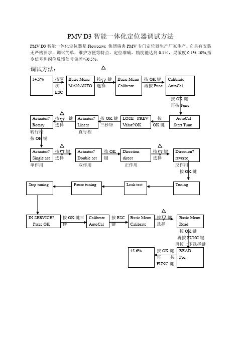
PMV D3智能一体化定位器是Flowserve集团瑞典PMV专门定位器生产厂家生产。它具有安装无严格要求,调试简单,维护方便等特点。定位准确,精度能达到0.1%,灵敏度0.1%-10%,指令信号和阀位反馈信号偏差≤0.5%。
调试方法:
34.5%
按两次ESC
Basic Menu
按键选择
Basic Menu
Shift Menu
按OK键
Full menu
no
按上下键
选择
Tuning
close time
按OK键选择再按func键
Full menu
tuning
按键选择
Full menu
Man/auto
按OK键
Full menu
yes
按键选择
tuning
deadband
按OK键
再按func
MAN/AUTO
按键选择
Basic Menu
Calibrate
按OK键
再按Func
Calibrate
AutoCal
按OK键
再按Func
Actuator?
Rotary
按键选择
Actuator?
Linear
按OK键三秒钟
LOSE PREV Value?O Tune
转行程直行程
按OK键
Actuator?
Single act
按键选择
Actuator?
Double act
按OK键
Direction
direct
按键选择
Direction?
reverse
单作用双作用正作用反作用
- 1、下载文档前请自行甄别文档内容的完整性,平台不提供额外的编辑、内容补充、找答案等附加服务。
- 2、"仅部分预览"的文档,不可在线预览部分如存在完整性等问题,可反馈申请退款(可完整预览的文档不适用该条件!)。
- 3、如文档侵犯您的权益,请联系客服反馈,我们会尽快为您处理(人工客服工作时间:9:00-18:30)。
按键选择
Basic Menu
Calibrate
按OK键
再按Func
Calibrate
AutoCal
按OK键
再按Func
Actuator?
Rotary
按键选择
Actuator?
Linear
按OK键三秒钟
LOSE PREV Value?OK
按OK键
AutoCal
Start Tune
转行程直行程
Deadband=0.5%
按func键再按改变数值
deadband=1.5%
按OK键
再按ESC
Full menu
man/auto
按键选择Байду номын сангаас
Full Menu
Read
按OK键
再按FUNC键
再按上下选择键
45.6%
按OK键
再按FUNC键
READ
Pos
PMV D3智能一体化定位器调试方法
PMV D3智能一体化定位器是Flowserve集团瑞典PMV专门定位器生产厂家生产。它具有安装无严格要求,调试简单,维护方便等特点。定位准确,精度能达到0.1%,灵敏度0.1%-10%,指令信号和阀位反馈信号偏差≤0.5%。
调试方法:
34.5%
按两次ESC
Basic Menu
按OK键
Actuator?
Single act
按键选择
Actuator?
Double act
按OK键
Direction
direct
按键选择
Direction?
reverse
单作用双作用正作用反作用
按OK键
Step tuning
Pause tuning
Leaktest
Tuning
IN SERVICE?
按键选择
Basic Menu
Shift Menu
按OK键
Full menu
no
按上下键
选择
Tuning
close time
按OK键选择再按func键
Full menu
tuning
按键选择
Full menu
Man/auto
按OK键
Full menu
yes
按键选择
tuning
deadband
按OK键
再按func
Press OK
按OK键三秒
Calibrate
AutoCal
按ESC键
Basic Menu
Calibrate
按键选择
Basic Menu
Read
按OK键
再按FUNC键
再按上下选择键
45.6%
按OK键
再按FUNC键
READ
Pos
死区(灵敏度)的调整方法:
34.5%
按两次ESC
Basic Menu
MAN/AUTO
