L301操作说明书
Epson产品使用说明书
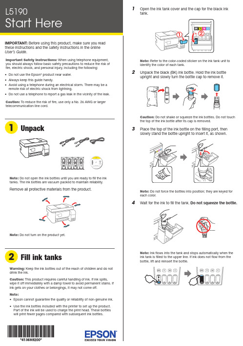
Do not open the ink bottles until you are ready to fill the ink tanks. The ink bottles are vacuum packed to maintain reliability.emove all protective materials from the product.11 Select your language, country, date, and time.Note: You can change these settings later using the product’scontrol panel. For more information see the online User’s Guide.12 W hen instructed to see the Start Here sheet, press andhold the help button for 5 seconds.13 P ress the start button to start ink charging.Note: Ink charging takes about 10 minutes. When the power light stops flashing, ink charging is complete. Once initial setup of the printer is complete, you can top off the ink tanks with any remaining ink. See the online User’s Guidefor instructions.C aution: Do not unplug or turn off the product, or open theinner cover while the product is charging or you’ll waste ink. 14 PressSee the online User’s Guide for information about loading capacity and available paper types and sizes.1 M ake sure the product is not charging ink. Then raise thepaper support and tilt it backwards slightly.2 Slide the edge guides all the way out.Note: If you are using a Mac or your computer does not have aCD/DVD drive, an Internet connection is required to obtain the product software.To print from a Chromebook™, go to.jm/support/gcp for instructions.1 M ake sure the product is NOT CONNECTED to yourcomputer.Windows ®: If you see a Found New Hardware screen, clickCancel and disconnect the USB cable.2I nsert the product CD (Windows only) or download andrun your product’s software package. For the latest software, visit .jm/support/L5190.3 F ollow the instructions on the computer screen to run the setup program.4 W hen you see the Select Your Connection screen, selectone of the following:• Wireless connectionIn most cases, the software installer automatically attempts to set up your wireless connection. If setup is unsuccessful, you may need to enter your network name (SSID) and password.• Direct USB connectionMake sure you have the USB cable ready.• Wired network connectionMake sure you have an Ethernet cable (not included).Mobile printingConnect wirelessly from your smartphone, tablet, or computer. Print documents and photos from across the room or around the world:• Print directly from your iOS device. Simply connect your printer and device to the same network and tap the action icon to select the print option.• Use Epson Print Enabler (free from Google Play™) with Android™ devices (v4.4 or later). Then connect your printer and device to the same network and tap the menu icon to select the print option.• Print remotely with Epson Connect™ and Google Cloud Print™. See your online User’s Guide for instructions or learn more at .jm/connect .3 L oad A4- or letter-size paper, glossy or printable side upand short edge first, in the middle of the rear paper feedslot.Note:guides.4 S lide the edge guides against the paper, but not tootightly.5 P6 W hen prompted, use the arrow and OK buttons to selectAdjust to adjust print quality now, or select Adjust Laterto do so at another time.For instructions on loading envelopes or legal-size paper, see the online User’s Guide.1 C onnect the phone cord to a telephone wall jack andto the LINE port on your product. See the online User’sGuidefor more information.2 P ress the OK button to set up the fax, or press the #pound button to set it up later.EPSON is a registered trademark, EPSON Exceed Your Vision is a registered logomark, and Epson Connect is a trademark of Seiko Epson Corporation.Designed for Excellence is a trademark of Epson America, Inc.Mac is a trademark of Apple Inc., registered in the U.S. and other countries.Windows is a registered trademark of Microsoft Corporation in the United States and/or other countries.Android, Google Cloud Print, Chromebook, and Google Play are trademarks of Google LLC.General Notice: Other product names used herein are for identification purposes only and may be trademarks of their respective owners. Epson disclaims any and all rights in those marks.This information is subject to change without notice. © 2018 Epson America, Inc., 10/18CPD-56090Technical supportVisit .jm/support/L5190 to download drivers, view manuals, get FAQs, or contact Epson.You can also speak to a service technician by calling one of these numbers:Argentina(54 11) 5167-0300 Guatemala * 1-800-835-03580800-288-37766Mexico 01-800-087-1080Bolivia * 800-100-116 Mexico City (52 55) 1323-2052Chile (56 2) 2484-3400 Nicaragua * 00-1-800-226-0368Colombia 018000-915235 Panama * 00-800-052-1376Bogota (57 1) 592-2200 Paraguay 009-800-521-0019Costa Rica 800-377-6627 Peru 0800-10-126DominicanLima (51 1) 418-0210 Republic * 1-888-760-0068 Uruguay 00040-5210067Ecuador * 1-800-000-044 Venezuela (58 212) 240-1111El Salvador * 800-6570* C ontact your local phone company to call this toll-free number from a mobile phone.If your country does not appear on the list, contact your nearest Epson sales office. Toll or long distance charges may apply.Need paper and ink?Ensure brilliant results with Epson specialty papers, engineered specifically for Epson printers. You can purchase them from an Epson authorized reseller. To findthe nearest one, visit .jm or contact Epson as described in “Any questions?” on this sheet.L5190 replacement inks。
L301_303_111_UG打印机用户指南
其他选项 . . . . . . . . . . . . . . . . 24 打印照片的简单方法 . . . . . . . . . . 24 产品预置 ( 仅对于 Windows) . . . . . . . 25 双面打印 ( 仅对于 Windows) . . . . . . . 25
喷墨打印机 用户指南
目录
目录
版权和商标
版权和商标 . . . . . . . . . . . . . . . . 2
介绍
从何处查找信息 . . . . . . . . . . . . . . 6 注意、重要提示和注释 . . . . . . . . . . . 6 操作系统版本 . . . . . . . . . . . . . . . 6
仅使用随此产品附带的电源线,不要使用其他设备的电源线。在此产品上使用其他电源线或使用其他 设备的电源线可能会引起火灾或电击。 确保交流电源符合相关的当地安全标准。 除非按照该此产品指南中的特别说明进行操作外,请勿擅自拆卸,维修,或尝试维修电源线、扫描仪 部件或选件。 遇到下列情况时,应在断开此产品电源后与爱普生认证服务机构联系: 电源线或插头损坏、液体进入此产品、此产品摔落或机箱损坏,此产品不能正常运行或在性能上有明 显变化。( 不要调整操作指导中未提到的调节装置 ) 将此产品放置在靠近墙壁插座的地方,使插头容易拔下。 不要将此产品放置在户外,靠近较脏或较多尘土,靠近水、热源,置于震动、摇晃的物体上,或高温 或高湿的地方。 小心不要让液体进入此产品,也不要湿手操作此产品。 请勿将此产品放在低温或多尘的地方。 请妥善使用 / 保管此产品,以避免因使用 / 保管不当 (如鼠害、液体渗入等)造成故障、损伤。
310+ 矿业拨动单位 EATON 说明书
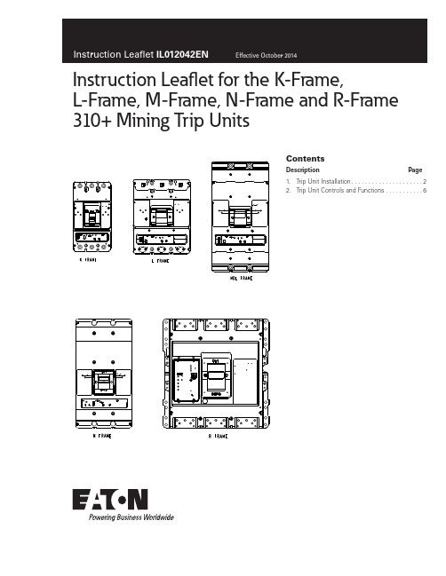
ContentsDescription Page 1. Trip Unit Installation .....................22. Trip Unit Controls and Functions .. (6)Instruction Leaflet for the K-Frame,L-Frame, M-Frame, N-Frame and R-Frame310+ Mining Trip Units2Instruction Leaflet IL012042ENEffective October 2014Instruction Leaflet for the K-Frame,L -Frame, M-Frame, N-Frame and R-Frame310+ Mining T rip UnitsEATON otee:N Wires for optional features only.WARNINGDO NOT ATTEMPT TO INSTALL OR PERFORM MAINTENANCE ON EQUIP-MENT WHILE IT IS ENERGIZED. DEATH OR SEVERE PERSONAL INJURY CAN RESULT FROM CONTACT WITH ENERGIZED EQUIPMENT. ALWAYS VERIFY THAT NO VOLTAGE IS PRESENT BEFORE PROCEEDING.1. Trip Unit InstallationFigure 1. K Frame InstallationFigure 2. K Frame InstallationFigure 3. K Frame InstallationFigure 4. K Frame InstallationFigure 5. K Frame Installation3Instruction Leaflet IL012042ENEffective October 2014Instruction Leaflet for the K-Frame,L -Frame, M-Frame, N-Frame and R-Frame 310+ Mining T rip UnitsEATON Figure 6. L Frame Installation .Figure 7. L Frame InstallationFigure 8. L Frame Installation .Figure 9. L Frame InstallationFigure 10. L Frame Installation4Instruction Leaflet IL012042ENEffective October 2014Instruction Leaflet for the K-Frame,L -Frame, M-Frame, N-Frame and R-Frame310+ Mining T rip UnitsEATON Figure 11. M Frame InstallationFigure 12. M Frame InstallationFigure 13. M Frame InstallationFigure 14. M Frame InstallationFigure 15. M Frame Installation5Instruction Leaflet IL012042ENEffective October 2014Instruction Leaflet for the K-Frame,L -Frame, M-Frame, N-Frame and R-Frame 310+ Mining T rip UnitsEATON Figure 16. N FrameFigure 17. R FrameT able 1. Parts ListK Mining Trip UnitIL FOR 310+ MINING TRIP UNITS 310+ MINING NOTIFICATION DATA SHEETKIT, 310+ MINING K-FRAME SCREW & INSTRUCTION TAGL Mining Trip UnitIL FOR 310+ MINING TRIP UNITS 310+ MINING NOTIFICATION DATA SHEETM Mining Trip UnitIL FOR 310+ MINING TRIP UNITS310+ MINING NOTIFICATION DATA SHEET6Instruction Leaflet IL012042ENEffective October 2014Instruction Leaflet for the K-Frame,L -Frame, M-Frame, N-Frame and R-Frame310+ Mining T rip UnitsEATON 2. Trip Unit Controls and FunctionsK NameplateFigure 18. K NameplateCATKEM3100TKEM 3125TKEM 3150TMKEM 3150TKEM 3200TKEM 3225T2KEM 3225TMKEM 3225TKEM3225TM2KEM 3400T2KEM 3400TKEM 3400TMKEM3400TM2RANGE1111232233223POSITIONABCDEFGHRANGE 15075150200300500600800RANGE 2200300500600800100012501500RANGE 350060080010001250150020002500The K Mining trip units have thirteen styles as shown in the CAT row above. The suffixes describe Long delay and Instantaneous functionality.L/M NameplateFigure 19. L/M NameplateCAT LEM 400TM LEM 3400T LEM 3350T LEM 3300T LEM 3500T LEM 3600T LEM 3400TM2LEM 3400T2LEM 3600TM LEM 3600T2LEM 3600TM2LEM 3450T MEM 3800T MEM 3800T2MEM 3800TM MEM 3800TM2RANGE1111112345511313POSITIONABCDEFGHRANGE 150060080010001250150020002500RANGE 2666800106613331666200026663333RANGE 310001250150020002500300035004000RANGE 4750900120015001862225030003750RANGE 525003000350040005000250025002500The L Mining trip units have sixteen styles as shown in the CAT row above. The suffixes describe Long delay and Instantaneous functionality.7Instruction Leaflet IL012042ENEffective October 2014Instruction Leaflet for the K-Frame,L -Frame, M-Frame, N-Frame and R-Frame 310+ Mining T rip UnitsEATON N NameplateFigure 20. N NameplateCATE2NM3400E2NM3500E2NM3600E2NM3700E2NM3800E2NM3900E2NM310E2NM312RANGE11111222POSITIONABCDEFGHRANGE 150060080010001250150020002500RANGE 212501500200025003000350040005000The N Mining trip units have EIGHT styles as shown in the CAT row above. The suffixes describe Long delay and Instantaneous functionality.The Instantaneous Trip Setting switch (A -H) allows current selec-tion over the range as shown in the tables above. The SHORT Time switch has three flat time settings: Inst (50ms), 100ms, and 300ms.Time-Current Trip Curve numbers for the LEM Mining are: TC01217001E and can be found on the Eaton Website at .R Nameplate 1600A & 2000A LS, LSIFigure 21. R Frame IL NameplateFigure 22. Alarm Relay (L/M Mining Frame)Figure 23. RMM Relay (L\M Mining Frame)GRN YELALARM RELAYCABLE12NRD40041+10-3W12NC14NO18W29NC27NO2K3CONT 2A 24VDC TQ2SA-24VK1J7-7J7-8J78Instruction Leaflet IL012042ENEffective October 2014Instruction Leaflet for the K-Frame,L -Frame, M-Frame, N-Frame and R-Frame310+ Mining T rip UnitsEATON Feature Notes1. Test Port - A test port is built into each trip unit to allow use of afunctional test kit. The test kit performs a test of the Long Delay, Short Delay. (Plug-In Test Kit Catalog #MTST230V )2. Test LED - To be used with a no trip functional test. This LED isa dual function light. The LED is used as a no trip indicator when using the test port. In normal modes, this LED indicates a high load alarm. It will light if the continuous current is 105% of the I r Setting and must be present for a 38 second duration.3. The long delay time is based on 6 x (6 I n ) @ 10 seconds.Example: A 400A mining with a current of 6x400 (2400A) will trip in 10 seconds.4. l sd - For short circuit conditions that exceed the short delay pick-up setting, the trip unit initiates a trip after a predetermined delay. (A-H)Trip Unit Current Rating (A)125250400600800120016002000Override Current Setting (A)30004200440056206800144001750017500Notee: If a fault current exceeds these override values, the breaker will trip instantaneously (in approximately 20 milliseconds or less).5. For the LSI style, the short delay time is a flat response deter-mined by the t sd switch settings of INST 100ms, or 300ms.6. Status LED - A green status light indicates the operational statusof the trip unit. If the breaker is operating correctly, the LED will blink on for one second and off for one second.7. The High Load Alarm Relay option will provide a SPST contactclosure when the trip unit current equals or is greater than 105% of I n for a period of 38 seconds. At this point the alarm will be triggered, illuminating the Red LED on the trip unit face. If the current drops below the 105% value, the contact will open. The yellow and green wires that exit the right side of the breaker are the common (C) and normally open (NO) of this relay.otee:N The contact ratings of the relay are: 2A at 30 VDC and 0.5 A at 125 VAC.8. Remote Maintenance Mode (RMM) places the trip unit in the2.5x instantaneous mode. For example, a 400 A (I n ) KD breaker with the switch set to 2.5x would trip instantaneously when the current exceeded 1000 A.The Remote Maintenance Mode is enabled by applying 24VDC to the two wire cable that exits the left side of the breaker. The wires are color coded as follows:Y ellow=+24V and Black=common ground. A blue colored LED, on the trip unit lights when the breaker is the Remote Maintenance Mode.The lighted blue LED indicates that the instantaneous setting of the Maintenance Mode is enabled. This setting corresponds to 2.5x of I n . Turning the I sd switch on the trip unit has no effect on either the Maintenance Mode or the t sd settings while the blue LED is lit.Also, a relay contact closure indicates that the Maintenance Mode has been enabled. The blue and red wires are the C and NO contacts of this relay. The relay has a dual function: 1) enable RMM and 2) provide a contact closure indication that RMM is enabled.Both the yellow and black set of wires and the red and blue set of wires exit the left side of the breaker.otee:N The RMM and High Load Alarm contacts are rated at 2A at 30 VDC and 0.5A at 125 VAC.Figure 24. N Mining Frame Remote Maintenance Mode Wiring DiagramFigure 25. K Alarm Relay9Instruction Leaflet IL012042ENEffective October 2014Instruction Leaflet for the K-Frame,L -Frame, M-Frame, N-Frame and R-Frame 310+ Mining T rip UnitsEATON Notese:10Instruction Leaflet IL012042ENEffective October 2014Instruction Leaflet for the K-Frame,L -Frame, M-Frame, N-Frame and R-Frame310+ Mining T rip UnitsEATON Notese:11Instruction Leaflet IL012042ENEffective October 2014Instruction Leaflet for the K-Frame,L -Frame, M-Frame, N-Frame and R-Frame 310+ Mining T rip Units EATON Notese:EatonElectrical Sector1000 Eaton Boulevard Cleveland, OH 44122United States877-ETN-CARE (877-386-2273) © 2014 EatonAll Rights ReservedPrinted in USAPublication No. IL012042EN / TBG1159 Part Number: IL012042ENH01 October 2014Eaton is a registered trademark.All other trademarks are property of their respective owners.Instruction Leaflet IL012042EN Effective October 2014Instruction Leaflet for the K-Frame,L-Frame, M-Frame, N-Frame and R-Frame310+ Mining T rip UnitsThe instructions for installation, testing, maintenance, or repair herein are provided for the use of the product in general commercial applications and may not be appropriate for use in nuclear applica-tions. Additional instructions may be available upon specific request to replace, amend, or supplement these instructions to qualify them for use with the product in safety-related applications in a nuclear facility.The information, recommendations, descriptions, and safety nota-tions in this document are based on Eaton’s experience and judg-ment with respect to Retrofitting of Power Breakers. This instruction-al literature is published solely for information purposes and should not be considered all-inclusive. If further information is required, you should consult an authorized Eaton sales representative.The sale of the product shown in this literature is subject to the terms and conditions outlined in appropriate Eaton selling policies or other contractual agreement between the parties. This literature is not intended to and does not enlarge or add to any such contract. The sole source governing the rights and remedies of any purchaser of this equipment is the contract between the purchaser and Eaton. NO WARRANTIES, EXPRESSED OR IMPLIED, INCLUDING WARRANTIES OF FITNESS FOR A PARTICULAR PURPOSE OR MERCHANTABILITY, OR WARRANTIES ARISING FROM COURSE OF DEALING OR USAGE OF TRADE, ARE MADE REGARDING THE INFORMATION, RECOMMENDATIONS, AND DESCRIPTIONS CONTAINED HEREIN. In no event will Eaton be responsible to the purchaser or user in contract, in tort (including negligence), strict liability or otherwise for any special, indirect, incidental or conse-quential damage or loss whatsoever, including but not limited to damage or loss of use of equipment, plant or power system, costof capital, loss of power, additional expenses in the use of existing power facilities, or claims against the purchaser or user by its cus-tomers resulting from the use of the information, recommendations and description contained herein.。
InHand IR300系列工业级路由器用户手册说明书

InHand IR300系列工业级路由器用户手册资料版本:V1.2—2022.010声明首先非常感谢您选择本公司产品!在使用前,请您仔细阅读本用户手册。
非本公司书面许可,任何单位和个人不得擅自摘抄、复制本书内容的部分或全部,并不得以任何形式传播。
由于不断更新,本公司不能承诺该资料与实际产品一致,同时也不承担由于实际技术参数与本资料不符所导致的任何争议,任何改动恕不提前通知。
本公司保留最终更改权和解释权。
版权所有©北京映翰通网络技术股份有限公司及其许可者版权所有,保留一切权利。
本手册图形界面约定技术支持联络信息北京映翰通网络技术股份有限公司(总部)地址:北京市朝阳区紫月路18号院3号楼5层电话:(8610)6439 1099 传真:(8610)8417 0089成都办事处电话:************地址:四川省成都市高新区府城大道西段399号,天府新谷10栋1406室广州办事处电话:************地址:广州市天河区棠东东路5号远洋新三板创意园B-130单元武汉办事处电话:************地址:湖北省武汉市洪山区珞瑜东路2号巴黎豪庭11栋2001室上海办事处电话:************地址:上海市普陀区顺义路18号1103室目录一、设备简介 (1)1.1概述 (1)1.2包装清单 (1)1.2.1 适用于IR300设备系列 (1)1.3面板介绍 (2)1.3.1 适用IR300设备系列 (2)1.4状态指示灯说明 (3)1.4.1 适用于IR300设备系列 (3)二、设备安装 (4)2.1安装设备 (4)2.2SIM/UIM卡安装 (5)2.3天线安装 (5)2.4保护地接地安装 (5)2.5供电电源安装 (5)2.6访问设备 (5)2.6.1自动获取IP 地址(推荐使用) (6)2.6.2设置静态IP 地址 (6)2.6.3取消代理服务器 (7)2.6.4 登录/退出Web设置页面 (7)三、基本配置 (8)3.1系统 (8)3.1.1 基本设置 (8)3.1.2 系统时间 (9)3.1.3 管理控制 (9)3.1.4 系统日志设置 (11)3.1.5 配置管理 (12)3.1.6 计划任务 (13)3.1.7 系统升级 (13)3.1.8 重启系统 (13)3.1.9 退出系统 (13)3.2网络 (13)3.2.1 Cellular (13)3.2.2 WAN/LAN切换 (16)3.2.3 LAN 端口 (18)3.2.4 WLAN模式切换 (19)3.2.5 WLAN客户端(AP模式) (19)3.2.6 WLAN客户端(STA模式) (20)3.2.7 链路备份 (20)3.2.8 VRRP (21)3.2.9 IP Passthrough (22)3.2.10 静态路由 (23)3.3服务 (23)3.3.1 DHCP服务 (24)3.3.2 域名服务器 (24)3.3.3 DNS转发 (25)3.3.4 动态域名 (26)3.3.5 设备远程管理平台 (27)3.3.6 SNMP(简单网络管理协议) (28)3.3.7 SNMP TRAP (28)3.3.8 I/O (29)3.3.9 DTU (29)3.3.10 短信 (31)3.3.11 流量管理 (31)3.3.12 告警设置 (32)3.3.13 用户体验计划 (32)3.4防火墙 (33)3.4.1 基本设置 (33)3.4.2 访问控制 (33)3.4.3 内容过滤 (34)3.4.4 端口映射 (34)3.4.5 虚拟IP映射 (35)3.4.6 DMZ设置 (36)3.4.7 MAC-IP绑定 (36)3.4.8 NAT (36)3.5带宽管理 (37)3.5.1 IP限速 (37)3.6VPN设置 (38)3.6.1 IPSec基本参数 (39)3.6.2 IPSec隧道配置 (40)3.6.3 GRE隧道配置 (42)3.6.4 L2TP客户端配置 (43)3.6.5 PPTP客户端配置 (45)3.6.6 OpenVPN配置 (46)3.6.7 OpenVPN高级配置 (47)3.6.8 证书管理 (48)3.7工具 (49)3.7.1 PING探测 (49)3.7.2 路由探测 (50)3.7.3 网速测试 (50)3.8行业应用 (50)3.8.1 Smart ATM (50)3.8.2 Status Report (51)3.8.3 Smart-EMS (52)3.9状态 (53)3.9.1 系统状态 (53)3.9.2 Modem状态 (53)3.9.3 流量状态 (53)3.9.4 告警状态 (53)3.9.5 WLAN状态 (53)3.9.6 网络连接 (54)3.9.7 设备管理平台 (54)3.9.8 路由状态 (54)3.9.9 设备列表 (54)3.9.10 系统日志 (54)附录A 故障处理 (55)附录B 命令行指令说明 (56)一、设备简介1.1 概述IR300系列产品,是集3G/4G网络、虚拟专用网等技术于一体的物联网无线路由器产品。
条形码读取器BCL300i和BCL301i的01-10 2011版本50117107技术说明书
BCL300i and BCL301iBar code Readerse n 01-10/201150117107T E C H N I C A L D E S C R I P T I O N©All right s re s erved, e s peci a lly the right of reprod u ction, di s tri bu tion a nd tr a n s l a tion. Copying or reprod u ction s in a ny form req u ire the written con s ent of the m a n u f a ct u rer.Prod u ct n a me s us ed witho u t g ua r a ntee of free usab ility.Ch a nge s reflecting technic a l improvement s m a y b e m a de.Table of content s1General information (9)1.1Explanation of s ymbol s (9)1.2Declaration of conformity (9)2S afety notice s (10)2.1General s afety notice s (10)2.2S afety s tandard s (10)2.3Approved purpo s e (10)2.4Workin g s afely (11)3Fa s t commi ss ionin g / operatin g principle (13)3.1Mountin g the BCL300i \ BCL301i (13)3.2Device arran g ement and s election of the mountin g location (13)3.3Electrical connection BCL300i (14)3.4Electrical connection BCL301i (18)3.5S tartin g the device (22)3.6Bar code readin g (24)4Device de s cription (25)4.1About the bar code reader s of the BCL300i s erie s (25)4.2Characteri s tic s of the bar code reader s of the BCL300i s erie s (26)4.3Device con s truction (28)4.4Readin g technique s (32)4.4.1Line s c a nner (s ingle line) (32)4.4.2Line s c a nner with o s cill a ting mirror (33)4.4.3R as ter s c a nner (R as ter Line) (34)4.5S tandalone connectionBCL300i (35)4.6Networkin g - Leuze multiNet plu s BCL301i (36)4.7Leuze multi S can (36)4.8Heater (38)4.9External parameter memory (38)4.10autoReflAct (39)4.11Reference code s (39)4.12autoConfi g (40)Le u ze electronic BCL300i \ BCL301i1Table of content s5S pecification s (41)5.1General s pecification s of the bar code reader s (41)5.1.1Line s c a nner / r as ter s c a nner (41)5.1.2O s cill a ting-mirror s c a nner (43)5.1.3Line s c a nner / r as ter s c a nner with deflection mirror (43)5.2Heatin g model s of the bar code reader s (44)5.2.1Line s c a nner / r as ter s c a nner with he a ter (45)5.2.2O s cill a ting-mirror s c a nner with he a ting (45)5.2.3Line s c a nner / r as ter s c a nner with deflection mirror a nd he a ting (46)5.3Dimen s ioned drawin gs (47)5.3.1Dimen s ioned dr a wing of complete overview of the BCL300i \ BCL301i with M S3xx / MK3xx (47)5.3.2Dimen s ioned dr a wing of complete overview of the BCL300i \ BCL301i with KB301-3000 (47)5.3.3Dimen s ioned dr a wing of line s c a nner with / witho u t he a ting (48)5.3.4Dimen s ioned dr a wing of deflection mirror s c a nner with / witho u t he a ting (49)5.3.5Dimen s ioned dr a wing of o s cill a ting-mirror s c a nner with / witho u t he a ting (50)5.3.6Dimen s ioned dr a wing of M S3xx hood with integr a ted connector s /MK3xx termin a l hood515.3.7Dimen s ioned dr a wing of KB301-3000 c ab le hood (52)5.3.8Dimen s ioned dr a wing of MA100 termin a l b ox (53)5.4Readin g field curve s / optical data (54)5.4.1B a r code ch a r a cteri s tic s (54)5.4.2R as ter s c a nner (55)5.5Readin g field curve s (56)5.5.1High Den s ity (N) - optic s: BCL300i \ BCL301i S/R1 N102 (H) (57)5.5.2High Den s ity (N) - optic s: BCL300i \ BCL301i S/R1 N100 (H) (57)5.5.3High Den s ity (N) - optic s: BCL300i \ BCL301i ON100 (H) (58)5.5.4Medi u m Den s ity (M) - optic s: BCL300i \ BCL301i S/R1 M102 (H) (59)5.5.5Medi u m Den s ity (M) - optic s: BCL300i \ BCL301i S/R1 M100 (H) (59)5.5.6Medi u m Den s ity (M) - optic s: BCL300i \ BCL301i OM100 (H) (60)5.5.7Low Den s ity (F) - optic s: BCL300i \ BCL301i S/R1 F102 (H) (61)5.5.8Low Den s ity (F) - optic s: BCL300i \ BCL301i S/R1 F100 (H) (61)5.5.9Low Den s ity (F) - optic s: BCL300i \ BCL301i OF100 (H) (62)5.5.10Ultr a Low Den s ity (L) - optic s: BCL300i \ BCL301i S/R1 L102 (H) (63)5.5.11Ultr a Low Den s ity (L) - optic s: BCL300i \ BCL301i S/R1 L100 (H) (63)5.5.12Ultr a Low Den s ity (L) - optic s: BCL300i \ BCL301i OL100 (H) (64)2BCL300i \ BCL301i Le u ze electronicTable of content s6In s tallation and mountin g (65)6.1S tora g e, tran s portation (65)6.2Mountin g the BCL300i \ BCL301i (66)6.2.1F as tening with M4 x 5 s crew s (66)6.2.2BT 56 mo u nting device (67)6.2.3BT 59 mo u nting device (69)6.3Device arran g ement (70)6.3.1S electing a mo u nting loc a tion (70)6.3.2Avoiding tot a l reflection – Line s c a nner (71)6.3.3Avoiding tot a l reflection – deflection mirror s c a nner (71)6.3.4Avoiding tot a l reflection – o s cill a ting-mirror s c a nner (72)6.3.5Mo u nting loc a tion (72)6.3.6Device s with integr a ted he a ting (73)6.3.7Po ss i b le re a ding a ngle s b etween BCL300i \ BCL301i a nd ba r code (73)6.4Cleanin g (74)7Electrical connection (75)7.1S afety notice s for the electrical connection (77)7.2Electrical connection BCL300i (78)7.2.1M S300 hood with 2 integr a ted M12 connector s (78)7.2.2MK300 termin a l hood with s pring-lo a ded termin a l s (79)7.2.3MA100 termin a l b ox a nd corre s ponding KB301-3000 c ab le hood (81)7.2.4KB301-3000 c ab le hood (82)7.2.5S t a nd a lone oper a tionBCL300i (82)7.3Electrical connection BCL301i (83)7.3.1M S301 hood with 3 integr a ted M12 connector s (83)7.3.2MK301 termin a l hood with s pring-lo a ded termin a l s (84)7.3.3MA100 termin a l b ox a nd corre s ponding KB301-3000 c ab le hood (86)7.3.4Network oper a tion BCL301i in the Le u ze m u ltiNet pl us (87)7.4Detailed de s cription of the connection s (88)7.4.1PWR / S W IN/OUT - Volt a ge su pply a nd s witching inp u t/o u tp u t s 1 a nd 2 (88)7.4.2S ERVICE – U S B interf a ce (Mini-B type) (90)7.4.3HO S T/BU S IN for BCL300i (91)7.4.4HO S T/BU S IN for BCL301i (93)7.4.5BU S OUT for the BCL301i (94)7.5Leuze multiNet plu s (95)7.5.1Wiring the m u ltiNet pl us (96)7.5.2The BCL301i as network s l a ve (97)7.6Cable len g th s and s hieldin g (97)Le u ze electronic BCL300i \ BCL301i3Table of content s8Di s play element s and di s play (98)8.1LED indicator s BCL300i \ BCL301i (98)8.2Di s play BCL300i \ BCL301i (100)9Leuze webConfi g tool (102)9.1Connectin g the S ERVICE U S B interface (102)9.2In s tallin g the required s oftware (103)9.2.1S y s tem req u irement s (103)9.2.2In s t a lling the U S B driver (103)9.3S tartin g the webConfi g tool (104)9.4S hort de s cription of the webConfi g tool (105)9.4.1Mod u le overview in the Config u r a tion men u (105)10Commi ss ionin g and confi g uration (107)10.1BCL300i (108)10.1.1Me asu re s to b e performed prior to the initi a l commi ss ioning (108)10.1.2S t a rting the device (108)10.2BCL301i - multiNet plu s S lave (109)10.2.1Me asu re s to b e performed prior to the initi a l commi ss ioning (109)10.2.2S t a rting the device (109)10.3Additional s ettin gs for the BCL300i and the BCL301i (110)10.3.1Decoding a nd proce ss ing the re a d d a t a (110)10.3.2Control of the decoding (112)10.3.3Control of the s witching o u tp u t s (113)10.4Tran s mittin g confi g uration data (114)10.4.1Vi a the we b Config tool (114)10.4.2Repl a cing a defective BCL300i \ BCL301i (114)11Online command s (115)11.1Overview of command s and parameter s (115)11.1.1Gener a l 'online' comm a nd s (116)11.1.2’Online’ comm a nd s for s y s tem control (123)11.1.3’Online’ comm a nd s for config u r a tion of s witching inp u t s/o u tp u t s (124)11.1.4’Online’ comm a nd s for the p a r a meter s et oper a tion s (127)12Dia g no s tic s and trouble s hootin g (134)12.1General cau s e s of error s (134)12.2Interface error s (134)4BCL300i \ BCL301i Le u ze electronicTable of content s13Type overview and acce ss orie s (136)13.1Part number code (136)13.2BCL300i (137)13.3BCL301i (138)13.4Connection hood / terminal box acce ss orie s (139)13.5Acce ss ory terminatin g re s i s tor (139)13.6Acce ss ory connector s (139)13.7Acce ss ory U S B cable (139)13.8Acce ss ory mountin g device (139)13.9Reflector acce ss orie s for autoReflAct (139)13.10Acce ss ory ready-made cable s for volta g e s upply (140)13.10.1Cont a ct ass ignment of PWR connection c ab le (140)13.10.2S pecific a tion s of the c ab le s for volt a ge su pply (140)13.10.3Order code s of the c ab le s for volt a ge su pply (140)13.11Acce ss ory ready-made cable s for bu s connection (141)13.11.1Gener a l inform a tion (141)13.11.2Cont a ct ass ignment R S485, connection c ab le KB PB... for m u ltiNet pl us. (141)13.11.3Cont a ct ass ignment R S232, connection c ab le KB SS I/IB S (142)13.11.4Technic a l d a t a of interf a ce connection c ab le s (142)13.11.5Order code interf a ce connection c ab le (142)14Maintenance (144)14.1General maintenance information (144)14.2Repair s, s ervicin g (144)14.3Di s a ss emblin g, packin g, di s po s in g (144)15Appendix (145)15.1Declaration of Conformity (145)15.2A S CII character s et (147)15.3Bar code s ample s (151)15.3.1Mod u le 0.3 (151)15.3.2Mod u le 0.5 (152)Le u ze electronic BCL300i \ BCL301i5Fi g ure s and table sFigure 2.1:Attachment of the stick-on labels with warning notices at the BCL300i \ BCL301i (12)Figure 3.1:BCL300i - MS300 hood with integrated M12 connectors (14)Figure 3.2:BCL300i - MK300 terminal hood with spring-loaded terminals (15)Figure 3.3:Cable fabrication for MK300 terminal hood (15)Figure 3.4:BCL300i - MA100 terminal box with KB301-3000 cable hood (16)Figure 3.5:BCL300i - KB301-3000 cable hood (17)Figure 3.6:BCL301i - MS301 hood with integrated M12 connectors (18)Figure 3.7:BCL301i - MK301 terminal hood with spring-loaded terminals (19)Figure 3.8:Cable fabrication for MK301 terminal hood (19)Figure 3.9:BCL301i - MA100 terminal box with KB301-3000 cable hood (20)Figure 4.1:Line scanner, line scanner with deflection mirror and oscillating-mirror scanner (25)Figure 4.2:Possible bar code orientation (27)Figure 4.3:BCL300i \ BCL301i device construction - line scanner (28)Figure 4.4:BCL300i \ BCL301i device construction -line scanner with deflection mirror (28)Figure 4.5:BCL300i \ BCL301i device construction - oscillating-mirror scanner (29)Figure 4.6:Device construction MS300/MS301 hood with integrated connectors (30)Figure 4.7:Device construction MK300/MK301 hood with integrated connectors (30)Figure 4.8:KB301/3000 cable hood device construction (31)Figure 4.9:MA100 terminal box device construction (31)Figure 4.10:Deflection principle for the line scanner (32)Figure 4.11:Deflection principle for the line scanner with oscillating mirror add-on (33)Figure 4.12:Deflection principle for the raster scanner (34)Figure 4.13:Standalone connectionBCL300i (35)Figure 4.14:Networking possibilities using the multiNet plus (36)Figure 4.15:Scanner arrangement with the multiScan function (37)Figure 4.16:Reflector arrangement for autoReflAct (39)Table 5.1:Specifications of the BCL301i and BCL300i line/raster scanners without heating (41)Table 5.2:Specifications of the BCL301i and BCL300i oscillating-mirror scanners without heating (43)Table 5.3:Specifications of the BCL301i and BCL300i deflection-mirror scanners without heating (43)Table 5.4:Specifications of the BCL301i and BCL300i line/raster scanners with heating (45)Table 5.5:Specifications of the BCL301i and BCL300i oscillating-mirror scanners with heating (46)Table 5.6:Specifications of the BCL301i and BCL300i deflection-mirror scanners with heating (46)Figure 5.1:Dimensioned drawing of complete overview of the BCL300i \ BCL301i with MS3xx / MK3xx (47)Figure 5.2:Dimensioned drawing of complete overview of the BCL300i \ BCL301i with KB301-3000 (47)Figure 5.3:Dimensioned drawing BCL300i \ BCL301i line scanner S...102.. (48)Figure 5.4:Dimensioned drawing BCL300i \ BCL301i deflection mirror scanner S...100 (49)Figure 5.5:Dimensioned drawing BCL300i \ BCL301i oscillating mirror scanner O...100.. (50)Figure 5.6:Dimensioned drawing of MS3xx hood with integrated connectors / MK3xx terminal hood (51)Figure 5.7:Dimensioned drawing of KB301-3000 cable hood (52)Figure 5.8:Dimensioned drawing of MA100 terminal box (53)Figure 5.9:The most important characteristics of a bar code (54)Table 5.7:Raster line cover as a function of the distance (55)Figure 5.10:Zero position of the reading distance (56)Table 5.8:Reading conditions (56)Figure 5.11:"High Density" reading field curve for line scanner without deflection mirror (57)Figure 5.12:"High Density" reading field curve for line scanner with deflection mirror (57)Figure 5.13:"High Density" reading field curve for oscillating-mirror scanners (58)Figure 5.14:Lateral "High Density" reading field curve for oscillating-mirror scanners (58)6BCL300i \ BCL301i Le u ze electronicFi g ure s and table s Figure 5.15:"Medium Density" reading field curve for line scanner without deflection mirror (59)Figure 5.16:"Medium Density" reading field curve for line scanner with deflection mirror (59)Figure 5.17:"Medium Density" reading field curve for oscillating-mirror scanners (60)Figure 5.18:Lateral "Medium Density" reading field curve for oscillating-mirror scanners (60)Figure 5.19:"Low Density" reading field curve for line scanner without deflection mirror (61)Figure 5.20:"Low Density" reading field curve for line scanner with deflection mirror (61)Figure 5.21:"Low Density" reading field curve for oscillating-mirror scanners (62)Figure 5.22:Lateral "Low Density" reading field curve for oscillating-mirror scanners (62)Figure 5.23:"Ultra Low Density" reading field curve for line scanner without deflection mirror (63)Figure 5.24:"Ultra Low Density" reading field curve for line scanner with deflection mirror (63)Figure 5.25:"Ultra Low Density" reading field curve for oscillating-mirror scanners (64)Figure 5.26:Lateral "Ultra Low Density" reading field curve for oscillating-mirror scanners (64)Figure 6.1:Device name plate BCL300i \ BCL301i (65)Figure 6.2:Fastening options using M4x5 threaded holes (66)Figure 6.3:BT 56 mounting device (67)Figure 6.4:Mounting example of BCL300i \ BCL301i with BT56 (68)Figure 6.5:BT 59 mounting device (69)Figure 6.6:Total reflection – line scanner (71)Figure 6.7:Total reflection – line scanner (71)Figure 6.8:Total reflection – BCL300i \ BCL301i with oscillating mirror (72)Figure 6.9:Reading angle for the line scanner (73)Figure 7.1:Location of the electrical connections (76)Figure 7.2:BCL300i - MS300 hood with integrated M12 connectors (78)Figure 7.3:BCL300i - MK300 terminal hood with spring-loaded terminals (79)Figure 7.4:Cable fabrication for MK300 terminal hood (79)Figure 7.5:BCL300i - MA100 terminal box with KB301-3000 cable hood (81)Figure 7.6:BCL300i - KB301-3000 cable hood (82)Figure 7.7:BCL301i - MS301 hood with integrated M12 connectors (83)Figure 7.8:BCL301i - MK301 terminal hood with spring-loaded terminals (84)Figure 7.9:Cable fabrication for MK301 terminal hood (85)Figure 7.10:BCL301i - MA100 terminal box with KB301-3000 cable hood (86)Table 7.1:Pin assignment PWR / SW IN/OUT (88)Figure 7.1:Switching input connection diagram SWIO_1 and SWIO_2 (89)Figure 7.2:Switching output connection diagram SWIO_1 / SWIO_2 (90)Table 7.2:Pin assignment SERVICE – Mini-B type USB interface (90)Table 7.3:Pin assignment HOST / BUS IN BCL300i (91)Figure 7.3:BCL300i - Pin assignments - HOST / BUS IN as RS232 (92)Figure 7.4:BCL300i - Pin assignments - HOST / BUS IN as RS422 (92)Table 7.4:Pin assignment HOST / BUS IN BCL301i (93)Table 7.5:Pin assignment BUS OUTBCL301i (94)Figure 7.5:Leuze multiNet plus system topology (95)Figure 7.6:Leuze multiNet plus system topology (96)Table 7.6:Cable lengths and shielding (97)Figure 8.1:BCL300i \ BCL301i - LED indicators (98)Figure 8.2:BCL300i \ BCL301i - Display (100)Figure 9.1:Connecting the SERVICE USB interface (102)Figure 9.2:The start page of the webConfig tool (104)Figure 9.3:Module overview in the webConfig tool (105)Le u ze electronic BCL300i \ BCL301i7Fi g ure s and table sFigure 10.1:Storing configuration data in the webConfig tool (114)Table 12.1:General causes of errors (134)Table 12.2:Interface error (134)Table 13.2:Type overview BCL300i (137)Table 13.3:Type overview BCL301i (138)Table 13.4:Connection hoods / terminal boxes for the BCL300i \ BCL301i (139)Table 13.5:Terminating resistor for the BCL301i (139)Table 13.6:Connectors for the BCL300i \ BCL301i (139)Table 13.7:Service cable for the BCL300i \ BCL301i (139)Table 13.8:Mounting devices for the BCL300i \ BCL301i (139)Table 13.9:Reflector for autoReflAct operation (139)Table 13.10:PWR cables for the BCL300i \ BCL301i (140)Figure 13.11:Cable configuration multiNet plus connection cables (141)Table 13.12:Interface connection cable for the BCL300i \ BCL301i (142)Figure 15.1:Declaration of conformity BCL300i \ BCL301i (145)Figure 15.2:Connection hood / connector unit declaration of conformity (146)Figure 15.3:Bar code sample labels (module 0.3) (151)Figure 15.4:Bar code sample labels (module 0.5) (152)8BCL300i \ BCL301i Le u ze electronicGeneral information1General information1.1Explanation of s ymbol sThe s ym b ol s us ed in thi s technic a l de s cription a re expl a ined b elow.Attention!This symbol precedes text messages which must strictly be observed. Failure to comply with this information results in injuries to personnel or damage to the equipment.Attention Laser!This symbol warns of possible danger caused by hazardous laser radiation.Notice!This symbol indicates text passages containing important information.1.2Declaration of conformityThe ba r code re a der s of the BCL 300i s erie s h a ve b een developed a nd m a n u f a ct u red in a ccord a nce with the a pplic ab le E u rope a n s t a nd a rd s a nd directive s .Notice!You can find the Declaration of Conformity of the devices in the appendix of the manual on page 145.The m a n u f a ct u rer of the prod u ct, Le u ze electronic Gm b H & Co KG in D-73277 Owen,po ss e ss e s a certified q ua lity assu r a nce s y s tem in a ccord a nce with IS O 9001.S afety notice s2S afety notice s2.1General s afety notice sDocumentationAll entrie s in thi s technic a l de s cription m us t b e heeded, in p a rtic u l a r the pre s ent ch a pter "Sa fety notice s". Keep thi s technic a l de s cription in a sa fe pl a ce. It s ho u ld b e a v a il ab le a t a ll time s.Safety regulationsO bs erve the loc a lly a pplic ab le reg u l a tion s a nd the r u le s of the employer's li ab ility in su r a nce ass oci a tion.RepairRep a ir s m us t only b e c a rried o u t b y the m a n u f a ct u rer or a n au thorized repre s ent a tive.2.2S afety s tandard sThe ba r code re a der s of the BCL300i s erie s were developed, m a n u f a ct u red a nd te s ted ina ccord a nce with the a pplic ab le sa fety s t a nd a rd s. They corre s pond to the s t a te of the a rt.2.3Approved purpo s eAttention!The protection of personnel and the device cannot be guaranteed if the device is operated in a manner not corresponding to its intended use.B a r code re a der s of the BCL300i s erie s a re conceived as s t a tion a ry, high-s peed s c a nner swith integr a ted decoder s for a ll c u rrent ba r code s us ed for au tom a tic o b ject detection.In p a rtic u l a r, u n au thorized us e s incl u de:•in room s with explo s ive a tmo s phere s•oper a tion for medic a l p u rpo s e sAreas of applicationThe ba r code re a der s of the BCL300i s erie s a re e s peci a lly de s igned for the following a re as of a pplic a tion:•S tor a ge technology a nd m a teri a l s h a ndling, in p a rtic u l a r for o b ject identific a tion onf as t-moving tr a n s port s y s tem s•P a llet tr a n s port s y s tem s•A u tomo b ile s ector•Omnidirection a l re a dingS afety notice s2.4Workin g s afelyAttention!Access and changes to the device, except where expressly described in this operating manual, are not authorized.Safety regulationsO bs erve the loc a lly a pplic ab le leg a l reg u l a tion s a nd the r u le s of the employer's li ab ility in su r a nce ass oci a tion.Qualified personnelMo u nting, commi ss ioning a nd m a inten a nce of the device m us t only b e c a rried o u t b y q ua lified per s onnel.Electric a l work m us t b e c a rried o u t b y a certified electrici a n.Attention, laser radiation!If you look into the beam path over a longer time period, the retina of your eye may be damaged!Never look directly into the beam path!Do not point the laser beam of the BCL 300i \ BCL 301i at persons!When mounting and aligning the BCL 300i \ BCL 301i , avoid reflections of the laser beam off reflective surfaces!The BCL 300i \ BCL 301i bar code readers correspond to the EN 60825-1 safety standard for a class 2 laser systems. They also comply with the U.S.21CFR 1040.10regulations for a class II laser product except for deviations pursuant to Laser Notice No. 50, dated July 26, 2001.Radiant Energy: The BCL 300i \ BCL 301i uses a low power visible laser diode. The emitted wavelength is 655nm. The average laser power is less than 1mW in accordance with the definition of laser class 2.Adjustments: Do not attempt any adjustments to or alterations of this product.Do not remove the protective housing of the bar code reader. There are no user-serviceable parts inside.The glass optics cover is the only aperture through which laser radiation may be observed on this product. A failure of the scanner motor, while the laser diode continues to emit a laser beam, may cause emission levels to exceed those for safe operation. The bar code reader has protective devices to prevent this occurrence. If,however, a stationary beam is emitted, the failing bar code reader should be discon-nected from the voltage supply immediately.CAUTION: Use of controls or adjustments or performance of procedures other thanspecified herein may result in hazardous light exposure.S afety notice sThe use of optical instruments or devices in combination with the device increases the danger of eye damage!The housing of the BCL300i \ BCL301i is provided with warning notices A and B above and next to the reading window as shown in the following figure:Fig u re 2.1:Att achment of the s tick-on lab el s with wa rning notice sa t the BCL 300i \ BCL 301iABCL 300i \ BCL 301i Line s canner andM12 M S 3xx connection hoodBCL 300i \ BCL 301i with o s cillatin g mirror and M12 M S 3xx connection hoodBA W a rning: l as er a pert u re BN a me pl a teBCL 300i \ BCL 301i with deflection mirror and M12 M S 3xx connection hoodFa s t commi ss ionin g / operatin g principle3Fa s t commi ss ionin g / operatin g principleBelow yo u will find a s hort de s cription for the initi a l commi ss ioning of the BCL 300i \BCL 301i . Det a iled expl a n a tion s for a ll li s ted point s c a n b e fo u nd thro u gho u t thi s technic a l de s cription.3.1Mountin g the BCL 300i \ BCL 301iThe BCL 300i \ BCL 301i ba r code re a der s c a n b e mo u nted in two different w a y s :•Vi a fo u r M4x6 s crew s on the b ottom of the device.•Vi a a BT 56 mo u nting device in the f as tening groove on the b ottom of the ho us ing.3.2Device arran g ement and s election of the mountin g locationIn order to s elect the right mo u nting loc a tion, s ever a l f a ctor s m us t b e con s idered:•S ize, orient a tion, a nd po s ition toler a nce of the ba r code s on the o b ject s to b e s c a nned.•The re a ding field of the BCL 300i \ BCL 301i in rel a tion to the ba r code mod u le width.•The re su lting minim u m a nd m a xim u m re a ding di s t a nce from the re s pective re a ding field.•The permi ss i b le c ab le length s b etween the BCL 300i \ BCL 301i a nd the ho s t s y s tem depending on which interf a ce i s us ed.•The correct time for d a t a o u tp u t. The BCL 300i \ BCL 301i s ho u ld b e po s itioned in su ch a w a y th a t, t a king into con s ider a tion the time req u ired for d a t a proce ss ing a nd the conveyor b elt s peed, there i s su fficient time to e.g. initi a te s orting oper a tion s on the bas i s of the re a d d a t a .•The di s pl a y a nd control p a nel s ho u ld b e very vi s i b le a nd a cce ss i b le.•For config u ring a nd commi ss ioning with the we b Config tool, the U S B interf a ce s ho u ld b e e as ily a cce ss i b le.For s pecific inform a tion, ple as e refer to ch a pter 6 a nd ch a pter 7.Notice!The beam exits the BCL 300i \ BCL301i as follows for the respective devices:- line scanner parallel to the housing base- deflection mirror 105degrees to the housing base - oscillating mirror perpendicular to the housing base.The black areas in figure 6.2 are the housing base. The best read results are obtained when:•The BCL 300i \ BCL 301i is mounted in such a way that the scanning beam is inci-dent on the bar code at an angle of inclination greater than ±10°…15° to vertical.•The reading distance lies in the middle area of the reading field.•The bar code labels are of good print quality and have good contrast ratios.•You do not use high-gloss labels.•There is no direct sunlight.Fa s t commi ss ionin g / operatin g principle 3.3Electrical connection BCL 300iFor the electric a l connection of the BCL 300i , 4 connection v a ri a nt s a re a v a il ab le.The volta g e s upply (18…30VDC) i s connected a cc. to the connection type s elected.2 freely pro g rammable s witchin g input s /output s for individ ua l a d a pt a tion to the re s pec-tive a pplic a tion a re a l s o a v a il ab le here. Det a iled inform a tion on thi s topic c a n b e fo u nd in ch a pter 7.4.1 a nd ch a pter 7.4.3.MS 300 hood with 2 integrated M12 connectorsFig u re 3.1:BCL 300i - M S 300 hood with integr a ted M12 connector sNotice!The shielding connection is done via the M12 connector housing.Notice!The integrated parameter memory for the simple replacement of the BCL 300i is located in the MS 300.Mini-B U S B s ocket (b ehind protective c a p)M12 pl u g (A-coded)M12 pl u g (B-coded)Blind c a pHood with integr a ted connector sM S 300Fa s t commi ss ionin g / operatin g principleMK 300 terminal hood with spring-loaded terminalsFig u re 3.2:BCL 300i - MK 300 termin a l hood with s pring-lo a ded termin a l sNotice!The integrated parameter memory for simple exchange of the BCL 300i is located in the MK 300.Cable fabrication and s hieldin g connectionRemove a pprox.78mm of the connection c ab le s he a thing. 15mm of s he a th of the s hielded line m us t b e freely a cce ss i b le.Fig u re 3.3:C ab le f ab ric a tion for MK 300 termin a l hoodThe s hield i s au tom a tic a lly cont a cted when the c ab le i s le a d into the met a l s crew fitting a nd f as tened when the cord grip i s clo s ed. Then le a d the individ ua l wire s into the termin a l s a ccording to the di a gr a m. Wire end s leeve s a re not nece ssa ry.Termin a l hood MK 300SERVICE21354GNDD+D-VBID Mini-B U S B s ocket (b ehind protective c ap)T e r m i n a l b l o c k P W R / S W I N /O U TT e r m i n a l b l o c k H O S T / B U S I NTermin a l de s ign a tionMK 300。
GE PLC 3i7i手册
实现卓越控制 不负您之所托凭藉从紧凑而经济的M icro 控制器到采用前沿科技的可编程自动化控制器的技术,以及开放灵活的工业计算机,GE Fanuc 提供多样化的产品和解决方案来满足您的确切需求。
因为我们将这些灵活的自动化产品与强大的、为我们所有控制器提供通用工程开发环境的应用软件相结合,所以不论是您的知识库还是应用都可以非常方便地从一个平台移植到另一个平台,控制系统可以方便地从一代升级到下一代。
PACSystems TM结合了灵活性、开放性以及高性能,摒弃了移植和转换造成的历史负担。
突破性的可编程自动化控制器概念(PAC)——一旦编成应用程序,可在多个硬件平台上运行。
在程序设计中,我们已验证的先进技术将给予你强大的动力和空前的灵活性。
Six Sigma 质量标准设计方法保证了超强的可靠性。
业界领先的质量与革新手掌大小的尺寸,强大且经济VersaMaxNano和M icro PLC 的一体化结构节约了盘柜空间。
了更多的功能。
R新的 PACSystems 系列控制器具有轻便的应用机制,使其能够通过简单地更改几个设置即可把原有的平个独特的解决方案来满足控制应用的需求。
既可单独使用,也可与 HMI 和控制软件捆绑使用。
VersaMax 把一系列离散量、模拟量、混合的和特殊的 I/O 模块包含在一个小型系统中,却提供了大型 PLC 的性能。
置功能多样的控制系统。
出众的网络和通信能力,使得您可以使用开放的网络来组网、传送数据、上载和下载程序并进行诊断。
易于集成新的技术到已安装的基本系统中。
控制器提块,通过各种各样的网络进行通信,并支持系一整套在线开发工具帮助您进行调试,并很快地解决问题;PACSystems 系统为现有的PLC 技术提供了增强的速度和能力,以进行高速处理和通信,同时还加强了存储任务例如配方储存和数据记集成的解决方案要求有开放的结构、大量的与其近的高级诊断功能相关联,系列已经成为复杂应用的工业标准,点数和大量用户可以进一步丰富其定制化的系统结构,总线的单板计算机模块和特殊模块,还是运动控制器,来定制用户化的单机或者是分布式调试应用软件 —— M achine Edition —— 一整套控制硬件的核心CPU................................................................................................................................................................................................................................................背板 (机架).......................................................................................................................................................................................................................电源模块....................................................................................................................................................................................................................................离散量I/O 模块 (输入).............................................................................................................................................................................................模拟量I/O 模块 (输入).............................................................................................................................................................................................RX3i 全新的8通道通用模拟量输入模块..............................................................................................................................................................离散量I/O 模块 (输出)...................................................................................................................................................................................................................模拟量I/O 模块 (输出)...................................................................................................................................................................................................................毫伏模拟量输入模块...............................................................................................................................................................................................................................RTD 输入模块 ...............................................................................................................................................................................................................................................张力输入模块................................................................................................................................................................................................................................................热电偶输入模块..........................................................................................................................................................................................................................................通讯模块............................................................................................................................................................................................................................................................特殊模块............................................................................................................................................................................................................................................................运动控制模块................................................................................................................................................................................................................................................本地和远程I/O 扩展模块.....................................................................................................................................................................................................................附件.......................................................................................................................................................................................................................................................................电缆............................................................................................................................................................................................................................................. .........................第一章 PACSystems RX3i 控制器.......................................................................................................................................................................................第二章 PACSystems RX7i 控制器....................................................................................................................................................................................CPU.............................................................................................................................................................................................................................................机架............................................................................................................................................................................................................................................电源...........................................................................................................................................................................................................................................离散量I/O 模块 (输入)...........................................................................................................................................................................................模拟量I/O 模块 (输入)..........................................................................................................................................................................................离散量I/O 模块 (输出)..........................................................................................................................................................................................模拟量I/O 模块 (输出)...........................................................................................................................................................................................I/O 接口模块.........................................................................................................................................................................................................................通信模块.................................................................................................................................................................................................................................特殊模块.................................................................................................................................................................................................................................扩展电源模块......................................................................................................................................................................................................................扩展机架.................................................................................................................................................................................................................................附件...........................................................................................................................................................................................................................................电缆...........................................................................................................................................................................................................................................目 录12346911162123242526282930323333353637383942454850515253545555第一章 PACSystems RX3i 控制器 1PACSystems RX3i 控制器第一章 PACSystems RX3i 控制器全新的控制器 RX3i 是 PACSystems 可编程自动化控制器 (PAC ) 家族的最新成员。
301温度控制器操作说明书

3.4 改变最大输出功率
注意:输出功率是一个特殊设定功能,不会在所有的炉子上 都有此功能。(参见第 7 章节) 在常显示界面 按住并保持翻页键 1.5 秒进入设置菜单界面 按翻页键直到显示出现 OPH1 用上、下键调节数值(%功率)。按一次显示当前数值,再按 一次或者持续按就会改变当前数值。 不用进行任何操作,数值就会保存。 注意:不要将此参数值(功率)增加到超过炉子的设计极限,或者高于正确的硅碳加热棒加热计算 值,否则加热元件和炉子会损坏。请参考相应加热炉或烘箱的操作说明书。
3.5 改变校准类型
在常显示界面 按住翻页键 1.5 秒进入设置菜单
7
按翻页键直到显示出现 按上、下键显示当前校准类型 按上、下键显示输入密码界面 按上、下键输入校准密码(参见 3.6 章节) 按翻页健确认密码 用上、下键选择校准类型 不用进行任何操作,数值就会保存。(参见第 8 章节)
3.6 校准密码
5
2.5 保持模式状态
在保持模式状态时,输出将中断;这可以在设定参数时,控制器不会随时按新参数启动工作。 保持模式状态时输出指示灯关闭,且显示屏上交替显示主菜单和 HOLD 字样。
进入保持模式状态: 启动常显示界面 同时按住上、下键保持 1.5 秒 当 HOLD 在显示器上闪烁时,表示已经进入保持模式状态
301 温度控制器
ห้องสมุดไป่ตู้操作说明书
(仅供参考,如有疑问, 按厂家英文说明书为准)
目
录
1 控制器和手册的介绍 …………………………………………………… 4 1.1 该手册的使用 …………………………………………………………… 4 1.2 PID 控制 ………………………………………………………………… 4 1.3 文中功能键图示说明 …………………………………………………… 4 2 基本操作 ………………………………………………………………… 4 2.1 快捷键 …………………………………………………………………… 4 2.2 指示灯 …………………………………………………………………… 5 2.3 系统菜单 ………………………………………………………………… 5 2.4 常显示界面 ……………………………………………………………… 5
L301系列静压液位计说明书

L301系列静压液位计安装使用说明书solution中国服务中心L301系列静压液位计安装使用说明书L301系列静压液位计采用美国SOLUTION(斯卢森)公司提供的陶瓷电容式传感器,是我公司为适应中国市场需求,而自行开发和生产的新一代液位测量仪表,该仪表具有性能可靠,安装简单和使用方便的特点,该系列有六种型号静压液位计:L301-1型为沉入缆式结构;L301-2型为沉入杆式结构;L301-3型为直装螺纹旋入式结构;L301-4型为直装法兰式结构,四者均具隔爆和本安型。
L301-5和L301-6接触介质部分材料为PTFE或哈氏合金,适用于强酸、强碱等强腐蚀介质测量,具本安防爆型。
L301-5型为沉入缆式结构;L301-6型为沉入杆式结构。
工作原理L301系列静压液位计通过压力传感器实现液位测量。
压力传感器探入或接触被测液体,受到一定的静压(P)。
此压力(P,MPa)与液体高度(h,m)的关系列为P=10ֿ³ρgh。
式中为被测液体密度(g/cm³),g为当地的重力和速度(m/s²)。
对于一定的被测介质和地点,ρ和g为常数,压力和液位高度成正比。
如此,通过压力传感器实现了液位测量。
技术数据防爆标志:隔爆型dllCT6〔不含乙炔〕(L301-1﹑L301-2﹑L301-3﹑L301-4﹑)本安型:ibllCT4本安型关联设备:KAS901安全限能器或LB803S型安全栅满度测量范围:L301-11~100M(隔爆型1~20m)L301-20.5~4m;L301-3、L301-42~100mL301-51~5m;L301-60.5~3m精度等级:0.2级,0.5级长期稳定性:优于0.1%/年环境温度:-20~70℃介质温度:-20~+60℃(L301-1、L301-5)-20~+80℃(L301-2、L301-6)-40~+130℃(L301-3、L301-4)变送器防护等级:IP65传感器防护等级:IP68电源电压:普通型13-30.5V DC;隔爆型12.5~30V DC本安型12.6~24V DC变送器输出:4~20Ma贮存环境温度:L301-1、L301-5-20~+60℃L301-2、L301-3、L301-4、L301-6-40~+85℃贮存环境湿度:﹤90%RH变送器外壳材料:压铸铝合金测量膜片密封外壳L301-1、L301-296%氧化铝陶瓷氟橡胶等1Cr18Ni9TiL301-3、L301-4316或哈氏合金等电子束焊1Cr18Ni9TiL301-5、L301-696%氧化铝陶瓷PTFE PTFE传感器材料LL301-1L301-2L301-2L301-2过程连接为GI1/2“过程连接为法兰过程连接为GI1/2〞过程连接为法兰1.传感器其它与左图所示同 1.传感器其它与左图所示同2.导气电缆 2.加长杆(Icr8NigTi无缝管)3.过程连接 3.过程连接4.变送器 4.变送器L301-4L301-31.隔离膜片 1.隔离膜片2.法兰 2.外螺纹3.电缆引入口 3.电缆引入口4.变送器 4.变送器安装时切勿碰损波纹板测量膜片L301-5L301-5L301-6L301-6传感器外壳为哈氏合金传感器外壳为PTFE传感器外壳为哈氏合金传感器外壳这PTFEPTFE配重Q=128 1.变送器 2.过程连接 3.法兰GB9119.6-88DNG5哈氏合金配重Q=70 4.加长杆 5.传感器 6.测量膜片1.电缆2.传感器具3.测量膜片4.配重L.加长杆长度L.电缆长度防爆型与防腐型液位计安装使用注意事项(一)隔爆型1.在爆炸危险区域开启液位变送器外壳时,必须切断仪表电源.2.把盖旋紧后务必将盖上的紧定螺纹旋紧.(二)本安型1.液位计应单独安装,尽量远离大功率设备,以避免电磁感应和静电感应.2.本安电路的外部导线应单独布置,不允许与高压电缆一起敷设.3.液位计到安全栅的连接导线应尽量缩短,禁止盘卷连接导线的分布电感,分布电容与液位计的等效电感,等效电容分别之和须少于安全栅规定的额定值(例如:当导线截面1mm2时,连接导线的总长度不大于1000米).4.为确保本安性能,用户不得随意更换器件,维修有困难应送本公司修理.5.变送器线路板上设有电源接线端子(端子下面有“+”“-”标记),接线后,端子的卡口外不得有裸铜线.(三)防腐型(L301-5、L301-6)L301-5、L301-6防腐型静压液位计电缆接触被测介质的材料系聚四氟乙烯.鉴于该材料比金属材料强度差、硬度低等特点,请用户在运输、拆包装和仪表安装过程中,防止仪表受到碰伤、摔损、冲击和折曲等损坏.另外,使用L301-5的用户需注意以下几点:1.切勿折曲电缆和损伤电缆表面;2.电缆和传感器、变送器之间不得拉拔;3.传感器外壳材料为PTFE的L301-5必需加配重(其材料为PTFE或哈氏合金C276),配重安装时请将传感器端部的护罩旋下,然后手持传感器将配重旋入,开始旋入时请注意将螺纹对正.4.传感器和配重一起投入介质时,请缓慢设放,切勿猛然掷入.安装方式安装方式图法兰连接螺纹连接分离式注意:L301-1、L301-5的导气电缆不可过分夹紧和折曲过锐L301-1、L301-5的安装方式有螺纹连接、法兰连接和分离式三种,法兰连接采用GB9119。
AIG-301系列高级物联网闸门设备说明书

AIG-300系列具有Arm®Cortex™-A7雙核心1GHz處理器、1個CAN連接埠、4個DI、4個DO、ThingsPro Edge軟體的進階IIoT閘道器,工作溫度-40至70°C特色與優點•ThingsPro Edge軟體簡化資料採集和裝置管理•ThingsPro Edge和Azure IoT Edge的無縫整合可實現簡單、可靠且安全的雲端連線•支援使用ThingsPro Proxy工具程式輕鬆部署裝置•提供強大的OTA功能,防止軟體升級過程中出現系統故障•配備安全啟動以防惡意軟體注入攻擊認證簡介AIG-301系列進階IIoT閘道器專為工業物聯網應用而設計,特別適用於嚴苛操作環境中的分散式和無人站點。
ThingsPro Edge和Azure IoT Edge軟體已預先載入並與AIG-301系列無縫整合,使用Azure雲端解決方案實現簡單、可靠、安全的感測器到雲端連線,用於資料採集和裝置管理。
使用ThingsPro Proxy工具程式,裝置部署過程比以往更容易。
由於強大的OTA功能,完全不需要擔心軟體升級過程中的系統故障。
啟用安全啟動功能後,您可以啟用AIG-301系列的啟動程序,以防惡意軟體注入。
外觀AIG-301-T-AZU-LXAIG-301美國、歐盟、AP和CN型號規格ComputerCPU Armv7Cortex-A7dual-core1GHzDRAM2GB DDR3LStorage Pre-installed16GB eMMC GB eMMCPre-installed OS Moxa Industrial Linux(Debian9,Kernel4.4)Computer InterfaceTPM TPM v2.0Ethernet Ports Auto-sensing10/100/1000Mbps ports(RJ45connector)x2Serial Ports RS-232/422/485ports x2,software selectable(DB9male)CAN Ports CAN2.0A/B x1(DB9male)Digital Input DIs x4Digital Output DOs x4USB2.0USB2.0hosts x1,type-A connectorsWi-Fi Antenna Connector RP-SMA x2(excluding AIG-301-AZU-LX/T-AZU-LX models)Cellular Antenna Connector SMA x SMA x2(excluding AIG-301-AZU-LX/T-AZU-LX models)GPS Antenna Connector SMA x SMA x1(excluding AIG-301-AZU-LX/T-AZU-LX models)Expansion Slots mPCIe slot x1:AIG-301-US-AZU-LX/T-US-AZU-LX,AIG-301-EU-AZU-LX/T-EU-AZULX,AIG-301-AP-AZU-LX/T-AP-AZU-LXmPCIe slot x2:AIG-301-CN-AZU-LX/T-CN-AZU-LXSIM Format Nano(AIG-301-US-AZU-LX/T-US-AZU-LX,AIG-301-EU-AZU-LX/T-EU-AZU-LX,AIG-301-AP-AZU-LX/T-AP-AZU-LX)Number of SIMs2Buttons Programmable buttonMagnetic Isolation Protection 1.5kV(built-in)Serial InterfaceConsole Port1x4-pin headerConnector DB9femaleBaudrate300bps to921.6kbpsData Bits5,6,7,8Flow Control ADDC®(automatic data direction control)for RS-485,RTS/CTS,XON/XOFF Parity None,Even,Odd,Space,MarkStop Bits1,1.5,2Isolation N/ASerial SignalsRS-232TxD,RxD,RTS,CTS,DTR,DSR,DCD,GNDRS-422Tx+,Tx-,Rx+,Rx-,GNDRS-485-2w Data+,Data-,GNDRS-485-4w Tx+,Tx-,Rx+,Rx-,GNDCAN InterfaceNo.of Ports1Connector DB9maleBaudrate10to1000kbpsIndustrial Protocols CAN2.0A,CAN2.0BSignals CAN_H,CAN_L,CAN_GND,CAN_SHLD,CAN_V+,GNDIsolation2kV(built-in)Digital InputsConnector Spring-type Euroblock terminalDry Contact Off:openOn:short to GNDWet Contact(DI to COM)On:10to30VDCOff:0to3VDCIsolation3K VDCSensor Type Wet contact(NPN)Dry contactDigital OutputsConnector Spring-type Euroblock terminalCurrent Rating200mA per channelI/O Type SinkVoltage24VDC nominal,open collector to30VDCCellular Standards LTE CAT-4Band Options(US)LTE Band2(1900MHz)/LTE Band4(1700MHz)/LTE Band5(850MHz)/LTE Band13(700MHz)/LTE Band17(700MHz)UMTS/HSPA850MHz/1900MHzCarrier Approval:Verizon,AT&TBand Options(EU)LTE Band1(2100MHz)/LTE Band3(1800MHz)/LTE Band5(850MHz)/LTE Band7(2600MHz)/LTE Band8(900MHz)/LTE Band20(800MHz)UMTS/HSPA850MHz/900MHz/1900MHz/2100MHzBand Option(APAC)LTE Band1(2100MHz)/LTE Band3(1800MHz)/LTE Band5(850MHz)/LTE Band7(2600MHz)/LTE Band8(900MHz)/LTE Band28(700MHz)UMTS/HSPA850MHz/900MHz/1900MHz/2100MHzGPS InterfaceReceiver Types72-channel u-blox M8engineGPS/GLONASS/GalileoAccuracy Position:2.5m CEPSBAS:2.0m CEPAcquisition Aided starts:3secCold starts:26secSensitivity Cold starts:-148dBmTracking:-164dBmLED IndicatorsSystem Power x2User x1SIM card indicator x1Wireless Signal Strength Cellular/Wi-Fi x6ThingsPro SoftwareThingsPro Proxy Utility YesAzure IoT Edge Preintegrated YesThingsPro Edge Preloaded YesPower ParametersNo.of Power Inputs Redundant dual inputsInput Voltage12to48VDCPower Consumption 4.8W(AIG-301-AZU-LX/T-AZU-LX)6.0W(AIG-301-CN-AZU-LX/T-CN-AZU-LX)8.4W(AIG-301-US-AZU-LX/T-US-AZU-LX,AIG-301-EU-AZU-LX/T-EU-AZU-LX,AIG-301-AP-AZU-LX/T-AP-AZU-LX)Input Current0.4A@12VDC(AIG-301-AZU-LX/T-AZU-LX)0.5A@12VDC(AIG-301-CN-AZU-LX/T-CN-AZU-LX)0.7A@12VDC(AIG-301-US-AZU-LX/T-US-AZU-LX,AIG-301-EU-AZU-LX/T-EU-AZULX,AIG-301-AP-AZU-LX/T-AP-AZU-LX)ReliabilityAutomatic Reboot Trigger External WDT(watchdog timer)Physical CharacteristicsHousing SECCMetalInstallation DIN-rail mounting,Wall mounting(with optional kit)IP Rating IP30Dimensions141.5x120x27mm(5.7x4.72x1.06in)(AIG-301-AZU-LX/T-AZU-LX)141.5x120x39mm(5.7x4.72x1.54in)(AIG-301-US-AZU-LX/T-US-AZU-LX,AIG-301-EU-AZU-LX/T-EU-AZU-LX,AIG-301-AP-AZU-LX/T-AP-AZU-LX,AIG-301-CN-AZU-LX/TCN-AZU-LX)Weight560g(1.23lb)(AIG-301-AZU-LX/T-AZU-LX)745g(1.64lb)(AIG-301-CN-AZU-LX/T-CN-AZU-LX)750g(1.65lb)(AIG-301-US-AZU-LX/T-US-AZU-LX,AIG-301-EU-AZU-LX/T-EU-AZU-LX,AIG-301-AP-AZU-LX/T-AP-AZU-LX)Environmental LimitsAmbient Relative Humidity5to95%(non-condensing)Operating Temperature Standard Temp.Models:-20to70°C(-4to158°F)(AIG-301-US-AZU-LX,AIG-301-EU-AZU-LX,AIG-301-AP-AZULX,AIG-301-CN-AZU-LX)-20to85°C(-4to185°F)(AIG-301-AZU-LX)Wide Temp.Models:-40to70°C(-40to158°F)(AIG-301-T-US-AZU-LX,AIG-301-T-EU-AZU-LX,AIG-301-TAP-AZU-LX,AIG-301-T-CN-AZU-LX)–40to85°C(-40to185°F)(AIG-301-T-AZU-LX)Storage Temperature(package included)-40to85°C(-40to185°F)Shock IEC60068-2-27Vibration2Grms@IEC60068-2-64,random wave,5-500Hz,1hr per axis(without USB devicesattached)Standards and CertificationsSafety UL62368-1,EN62368-1EMC EN55032/35,EN61000-6-2/-6-4EMI CISPR32,FCC Part15B Class AEMS IEC61000-4-2ESD:Contact:4kV;Air:8kVIEC61000-4-3RS:80MHz to1GHz:10V/mIEC61000-4-4EFT:Power:2kV;Signal:1kVIEC61000-4-6CS:10VIEC61000-4-8PFMFIEC61000-4-5Surge:Power:0.5kV;Signal:1kVGreen Product RoHS,CRoHS,WEEEHazardous Locations Class I Division2,ATEX(AIG-301-T-US-AZU-LX,AIG-301-T-EU-AZU-LX,AIG-301-T-AP-AZU-LX,AIG-301-T-AZU-LX)MTBFTime683,818hrs(AIG-301-US-AZU-LX/T-US-AZU-LX,AIG-301-EU-AZU-LX/T-EU-AZU-LX,AIG-301-AP-AZU-LX/T-AP-AZU-LX)794,092hrs(AIG-301-AZU-LX/T-AZU-LX)Standards Telcordia(Bellcore)Standard TR/SRWarrantyWarranty Period5yearsDetails See /tw/warranty Package ContentsDevice1x AIG-300Series computer Documentation1x quick installation guide1x warranty cardInstallation Kit1x DIN-rail kit(preinstalled)1x power jack尺寸AIG-301-T-AZU-LXAIG-301美國、歐盟、AP和CN型號訂購資訊Model Name CPU RAM Storage TPM mPCIe Slot1forLTE ModulemPCIe Slot2forWi-Fi ModuleOperatingTemperatureAIG-301-AZU-LX 1GHz DualCore2GB16GB Built-in––-20to85°CAIG-301-T-AZU-LX 1GHz DualCore2GB16GB Built-in––-40to85°CAIG-301-CN-AZU-LX 1GHz DualCore2GB16GB Built-in Reserved Reserved-20to70°CAIG-301-T-CN-AZU-LX 1GHz DualCore2GB16GB Built-in Reserved Reserved-40to70°CAIG-301-US-AZU-LX 1GHz DualCore2GB16GB Built-inUS region LTEmodulepreinstalledReserved-20to70°CAIG-301-T-US-AZU-LX 1GHz DualCore2GB16GB Built-inUS region LTEmodulepreinstalledReserved-40to70°CAIG-301-EU-AZU-LX 1GHz DualCore2GB16GB Built-inEurope regionLTE modulepreinstalledReserved-20to70°CAIG-301-T-EU-AZU-LX 1GHz DualCore2GB16GB Built-inEurope regionLTE modulepreinstalledReserved-40to70°CAIG-301-AP-AZU-LX 1GHz DualCore2GB16GB Built-inAPAC regionLTE modulepreinstalledReserved-20to70°CAIG-301-T-AP-AZU-LX 1GHz DualCore2GB16GB Built-inAPAC regionLTE modulepreinstalledReserved-40to70°C配件(選購)Power WiringCBL-PJTB-10Non-locking barrel plug to bare-wire cableMini DB9F-to-TB DB9female to terminal block connectorCablesCBL-F9DPF1x4-BK-100Console cable with4-pin connector,1mWi-Fi Wireless ModulesUC-8200-WLAN22-AC Wireless package for UC-8200V2.0or later with Wi-Fi module,2screws,2spacers,1heat sink,1pad AntennasANT-LTEUS-ASM-01GSM/GPRS/EDGE/UMTS/HSPA/LTE,1dBi,omnidirectional rubber-duck antennaANT-LTE-ASM-04BK704to960/1710to2620MHz,LTE omnidirectional stick antenna,4.5dBiANT-LTE-OSM-03-3m BK700-2700MHz,multiband antenna,specifically designed for2G,3G,and4G applications,3m cable ANT-LTE-ASM-05BK704-960/1710-2620MHz,LTE stick antenna,5dBiANT-LTE-OSM-06-3m BK MIMO Multiband antenna with screw-fastened mounting option for700-2700/2400-2500/5150-5850MHzfrequenciesANT-WDB-ARM-02022dBi at2.4GHz or2dBi at5GHz,RP-SMA(male),dual-band,omnidirectional antennaANT-GPS-OSM-03-3m BK3dBi at1575.42MHz,SMA(male),omnidirectional magnetic-base passive GPS antenna,3m cableANT-GPS-CSM-03-3m3dBi at1575.42MHz,SMA(male),directional passive GPS antenna,3m cableANT-GPS-OSM-05-3M26dBi at1575.42MHz,SMA(male),omnidirectional active GPS antenna,3m cableWall-Mounting KitsUC-8200Wall-mounting Kit Wall-mounting kit for UC-8200with4M3screws©Moxa Inc.版權所有.2021年12月29日更新。
南方电子水准仪DL-301说明书2008

数字水准仪使用手册DL-300引言感谢您购买DL-300系列数字水准仪。
为了更好地使用仪器,请仔细阅读本使用手册,并妥善保管以便日后查阅。
一般操作注意事项在使用本仪器之前,务必检查并确认该仪器各项功能运行正常。
●避免条码尺面和每节标尺联接处被弄脏或损伤在标尺存放或运输时条码尺面和联接处可能会受到碰撞和损伤,如果条码被弄脏或损伤就难以精确读数和测量,因为仪器需要读出标尺的黑白条形码作为电信号,仪器的测量精度也会由此而降低,有时甚至无法进行测量。
●三脚架水准仪应尽量使用木制三脚架,使用金属三脚架可能会产生晃动,从而影响测量精度,三脚架每根腿上的螺旋必须切实固紧。
●三角基座如果基座安装不正确,测量精度可能受到影响,经常检查基座上的校正螺丝,基座上的中心固定螺旋要旋紧。
●防止仪器受震在运输过程中,应尽可能减小震动,剧烈震动可能导致测量功能受损。
●小心搬动仪器搬动仪器时必须握住提手。
●避免仪器直接受到阳光照射长时间将仪器放置在高温(+50℃)环境下,会对仪器的使用产生不良的影响,不要将仪器的物镜对准太阳光,否则会损坏仪器内部的部件。
●避免温度突变仪器温度突变会导致测程缩短,当仪器从很热的汽车中搬出时,要让仪器逐渐适应周围的温度后方可使用。
●电池检查在作业前应确认电池剩余电量。
●条码标尺如果使用条码标尺,请带上手套。
安全使用标志为安全使用本公司产品,使操作员和其他人免受伤害以及使财产免于损失,我们将重要的警告标志贴在仪器上并插入说明书内。
在阅读“安全使用注意事项”和使用说明书前,请首先明白下列标志的含义。
显示含义WARNING 忽视该显示可能会导致重伤、死亡CAUTION 忽视该显示可能会导致人员伤害或损坏物体·伤害:指伤痛、烧伤、电击等·损坏:指对建筑物、仪器设备或家具引起严重的破坏。
安全使用注意事项WARNING·将仪器直接瞄准太阳会导致对眼睛的严重损坏不要将仪器对准太阳特别须要注意在太阳位置较低的时间(如在早晨或傍晚),或在阳光直接照射仪器物镜时,建议用手或伞遮挡一下阳光·可能会发生燃烧爆炸不要将仪器靠近燃烧的气体、液体使用,不要在煤矿中使用该仪器·使条码尺远离高压线或变电站因为标尺是一个电导体,雷电会导致严重伤害或死亡·在打雷、闪电时不要使用条码尺因为条码尺是一个电导体,雷电会导致严重伤害或死亡。
比亚迪L3型汽车使用说明书
上图所示的安全标记表示如此做”或“不可以让此发生。
车辆的识别号被分别贴在如图所示1的发动机舱内和仪表板的左上侧。
这是比亚迪L3轿车的车辆识别号。
用于车主登记。
制造厂铭牌2上也标有车辆识别号1.发动机冷冻液指示牌2.空调系统警示牌3.冷却风扇警示牌上图所示为油标指示牌,被贴在加油口盖内侧。
发动机编号发动机编号标明在如图所示的发动机气缸体上。
1.转速表2.车速表3.水温表4.里程表5.燃油表6.信息显示屏.智能钥匙——智能钥匙为所有侧门开锁和闭锁,包括电子智能钥匙和卡式智能钥匙两种。
其中电子智能钥匙可通过遥控按键在远处对车门进行开闭锁,紧急报警和寻车等功能。
.机械钥匙(在电子智能钥匙和卡式钥匙的号码表示在号码牌上,须将号码牌存放在旅行袋等安全处,不要放在车中。
如果钥匙丢失或需要备用钥匙时钥匙包括智能钥匙和机械钥匙钥匙号码牌电子智能钥匙1.闭锁开关取出电池。
2.开锁开关3.开关4.机械钥匙5.指示灯将新电池插入智能钥匙内,再将机械钥匙插入卡式智能钥匙。
1.下拉释放开关,取出机械钥匙。
2.使用平头螺丝刀或类似工具打开电子智能钥匙盖。
3.使用平头螺丝刀或类似工具拆下电量耗尽的电子智能钥匙电池。
将工具插入导向槽并按上图所示方向施加力,取出电池。
注意不要改装电池盖,以免引起故障。
4.将新电池的正极(+)面向上放到盒内,紧紧盖上电子智能钥匙盖,装好电池盖后将机械钥匙插入电子智能钥匙。
更换电池后,检查电子智能钥匙是否操作正常,如果电子智能钥匙仍然不能正常操作,可与比亚迪销售服务店联系。
起动功能激活区域已登记的智能钥匙在激活区域内时,进入功能和起动功能有如果使用卡式智能钥匙不能进入车内或者不能起动发动机时,则可能是电池电量耗尽,应尽快更换电池。
(请参见本章节中的“更换卡式智能钥匙电池”)为防止车辆被盗,如果车辆在防盗状态下,任一车门打开,系统都将发出4.确保指示灯开始闪烁之后,可以离开车辆。
由于从车内开锁车门会激活系统,因此在设定系统时绝不能让任何人留在车内。
Philips 42HFL3017D 专业 LED 电视说明书

PhilipsProfessional LED TV42" EasySuite+LEDDVB-T/C MPEG 2/442HFL3017DImpress your guests, most efficientlywith superior LED technologyThe best viewing experience in a thin and energy efficient LED TV. Allow your guests to buy premium content and use the latest remote technology for effortless installation.Advanced hotel features and future proof •Brilliant LED images with incredible contrast •MyChoice compatibility for recurring revenues•SmartInstall for easy remote installation and maintenance •Integrated Connectivity Panel•Full Hotel, Healthcare and Prison ModesDifferentiating guest experience•SmartInfo for branded hotel info pages even offline •ThemeTV Lite for easy channel navigation•Additional headphone connection for personal listening Sustainable and safe •Low power consumption•Green Button allows guest to save even more energy •Eco-friendly design & flame retardant housingHighlightsHotel, Hospital, Prison ModeAll required features for professional use in environments where more is required than in a living room. From volume and menu locking to more rigorous material testing, energy saving, anti-theft remote controls anddedicated Heathcare and Prison features to allow for niche market applications.MyChoice compatibleMyChoice offers a simple and low-cost way to offer your guests premium TV channels. At the same time it delivers an additional revenue stream which allows you to recover your initial TV investment.ThemeTV LiteThemeTV Lite offers an easy user interface that gives your guests the opportunity to navigate in the guest menu to find their own country channels, news and hotel information easily without the need of an interactive entertainment system.Integrated Connectivity PanelThe Integrated Connectivity Panel allows your guests to seamlessly connect their personal devices to your TV without the need of any external Connectivity Panel.Green ButtonWith the Green Button guests have thepossibility to save even more energy on the TV by opting for a higher backlight dimming or by switching off the screen when listening to radio. Another way to reduce a hotel'soperating cost while involving guests directly.Eco-friendly designSustainability is integral to the way Philips does business. Philips TVs are designed and produced according to our EcoDesign principles aimed at minimizing overallenvironmental impact, through lower power consumption, removal of hazardous substances, lower weight, more efficientpackaging and better recyclability. Philips TVs also have a special housing of flame retardant material. Independent tests carried out by emergency fire services have shown that whereas TVs can sometimes intensify fires caused by external sources, Philips TVs will not contribute to the fire.Full HD LED TVThe most advanced LED lighting technology in this Full HD LED TV combines an eye-catching minimalistic design with stunning image quality as well as the lowest power consumption in itscategory. On top of that, LED lightingtechnology does not contain any hazardous materials. Thus, with LED backlight you can enjoy low power consumption, highbrightness, incredible contrast, sharpness and vibrant colors.SmartInstallSmartInstall makes installation andmaintenance of your TVs effortless. With a simple to use web tool, you can now remotely configure and install your TVs without visiting any rooms! This saves you time and makes sure your guests are not disturbed. Whether it is updating the hotel info pages or installing new channels, SmartInstall can handle all.SmartInfoSmartInfo allows you to provide hotel or city information to your guests through Hotel Info. Your guests have access to hotel info pages which can be changed regularly and easily to keep your guests up to date with all the latestdevelopments in your hotel.Issue date 2022-04-21Version: 3.2.312 NC: 8670 000 92974EAN: 87 12581 65374 3© 2022 Koninklijke Philips N.V.All Rights reserved.Specifications are subject to change without notice. Trademarks are the property of Koninklijke Philips N.V. or their respective owners.SpecificationsPicture/Display•Diagonal screen size: 42 inch / 107 cm •Aspect ratio: 16:9•Panel resolution: 1920x1080p •Brightness: 400 cd/m²•Picture enhancement: Digital Crystal Clear, 100 Hz Perfect Motion Rate•Dynamic screen contrast: 100.000:1•Viewing angle: 178º (H) / 178º (V)•Color cabinet: high gloss black cabinet •Display: LED Full HDSupported Display Resolution•Computer inputs: up to 1920x1080 @ 60Hz •Video inputs: 24, 25, 30, 50, 60 Hz, up to 1920x1080pTuner/Reception/Transmission•Aerial Input: 75 ohm coaxial (IEC75)•TV system:PAL,SECAM•Video Playback: PAL, SECAM, NTSC•Digital TV: DVB-C MPEG4*, DVB-C MPEG2*, DVB-T MPEG2*, DVB-T MPEG4*Sound•Output power (RMS): 20W (2 x 10W)•Sound Enhancement: Auto Volume Leveler, Clear Sound, Incredible Surround, Treble and Bass ControlConnectivity•Number of HDMI connections: 3•EasyLink (HDMI-CEC): One touch play, System standby, Remote control pass-through, System audio control•Other connections: Antenna IEC75, Common Interface Plus (CI+), Digital audio out (coaxial), Headphone out, PC-in VGA + Audio L/R in, Bathroom speaker out, IR out •Number of AV connections: 1•Number of component in (YPbPr): 1•Number of scarts (RGB/CVBS):1•Number of USBs: 2•HDMI features:Audio Return ChannelConvenience•Ease of Installation: Plug & Play, Advanced Hotel Mode, Automatic Tuning System (ATS), PLL Digital Tuning, Automatic Channel Install(ACI), AutoProgram Naming, Autostore, Cloning of TVsettings via USB, Installation menu locking, Security menu access, Keyboard lock-out, Cloning of TV settings via RF•Ease of Use: Auto Volume Leveller (AVL), On Screen Display, Program List, Side Control, Graphical User Interface, 1 channel list analog/digital•Comfort: Hotel Guest features, Welcomemessage, Switch on channel, Volume limitation, Sleep timer•Interactive hotel features: Block automatic channel update, MyChoice, ThemeTV Lite•Prison mode: Txt, MHEG, USB, EPG, Sub block •Teletext: 1000 page Smart Text•Electronic Program Guide: 8 day Electronic Program Guide, Now + Next EPG•Screen Format Adjustments: 4:3, Movie expand 14:9, Movie expand 16:9, Widescreen, Subtitle Zoom, Super Zoom, Auto Format•Remote control type: 22AV1108A (RC6)•Remote Control: low battery detection, battery anti-theft protection•Firmware upgradeable: Firmware upgradeable via USB, Firmware upgradeable via RF •Other convenience: Kensington lock •Clock: Sleep Timer•Clock Enhancements: Synchro Time via TXT/DVBHealthcare•Control: Multi remote control•Convenience: Headphone out, Independent main speaker mute•Safety: Nurse call system compatible, Double isolation Class IIMultimedia Applications•Multimedia connections: USB•Video Playback Formats: H264/MPEG-4 AVC, MPEG-1, MPEG-2, MPEG-4, Containers: AVI, MKV, WMV9/VC1•Music Playback Formats: MP3•Picture Playback Formats: JPEGPower•Mains power: 220-240V, 50/60Hz •Ambient temperature: 5 °C to 35 °C •Annual energy consumption: 91 kW·h •Standby power consumption: <0.3W•Energy Label Class: A•Eu Energy Label power: 62 W•Power Saving Features: Eco mode, Picture mute (for radio)Green Specifications•Safety: Flame retardant housing •Low Power Standby •SmartPower EcoDimensions•Set dimensions (W x H x D): 977.2 x 589 x 42.9 mm•Set dimensions with stand (W x H x D): 977.2 x 628.7 x 210 mm•Box dimensions (W x H x D): 1205 x 702 x 160 mm •Product weight: 12.9 kg•Product weight (+stand): 15.3 kg •Weight incl. Packaging: 18.7 kg•VESA wall mount compatible: 400 x 400 mmAccessories•Included accessories: Remote Control, Batteries for remote control, Power cord, Table top stand, Warranty Leaflet•Optional accessories: Set up remote 22AV8573/00。
301温度控制器操作说明书

1 控制器和手册的介绍
1.1 该手册的使用
该手册介绍如何设置和操作 301 温度控制器;该手册必须与相关加热炉的使用手册结合起来阅 读理解。
对于复杂控制的加热炉,该手册不可避免地会出现一些技术专有名词。这些名词的解释在该手 册最后的“术语表”内。
1.2 PID 控制
301 控制器采用了 PID(比例 积分 微分)温度控制。该控制方式利用精确的数字控制系统来 调整加热元件的功率,使炉子温度能稳定保持在设定的温度。
或者
用上、下键调节数值。按一次,显示当前数值,再按一次或
者一直按就会改变当前数值(Hr:Min)。
不用进行任何操作,数值就会保存。
(更多的信息请参考第五章节,定时器)
6
3 高级操作
3.1 进入设置菜单
在常显示界面 按住翻页键 1.5 秒 显示出设置菜单的第一个参数界面
3.2 改变定时类型
在常显示界面
2.2 指示灯
输出显示
定时显示
当炉子正在加热时,此灯亮 计时器工作时,此灯亮
过温保护显示
通常情况下,绿灯亮。过温保护启动时,红灯闪烁。当 过温保护重起及等待温度降低时,红灯常亮。
2.3 系统菜单
301 温度控制器菜单分为 2 个部分:主菜单和设置菜单。主菜单包含所有的基本操作控制:温 度设置,升温速率设置和定时设置。设置菜单包括所有的参数设置:定时类型,定时段,输出功率 及用户校准。这些设置的改变取决于用户的输入以及产品的固有特性。
2.4 常显示界面
当打开控制器时,显示出常显示界面,其中显示炉子的实际温度和点相应键可以显示设置温度。 如果已进入某菜单,且 30 秒内没有按任何键,控制器会自动返回初始界面。
2.4.1 从主菜单到常显示界面
2L301B自动填充设备安装与服务说明书

Installation & Service Instructions:2L301BRemote Auto-Fill Device 06L, 16L, 07L, 17L ISSUED: November, 2003Supersedes: March, 1995Doc.# 2L301, ECN# 030539, Rev. 3WARNINGTo avoid unpredictable system behavior that can cause personal injury and property damage:•Disconnect electrical supply (when necessary) before installation, servicing, or conversion.•Disconnect air supply and depressurize all air lines connected to this product before installation, servicing, or conversion.•Operate within the manufacturer’s specified pressure,temperature, and other conditions listed in these instructions.•Medium must be moisture-free if ambient temperature is below freezing.•Service according to procedures listed in these instructions.•Installation, service, and conversion of these products must be performed by knowledgeable personnel who understand how pneumatic products are to be applied.•After installation, servicing, or conversion, air and electrical supplies (when necessary) should be connected and the product tested for proper function and leakage. If audible leakage is present, or the product does not operate properly, do not put into use.•Warnings and specifications on the product should not be covered by paint, etc. If masking is not possible, contact your local representative for replacement labels.WARNINGFAILURE OR IMPROPER SELECTION OR IMPROPER USE OF THE PRODUCTS AND/OR SYSTEMS DESCRIBED HEREIN OR RELATED ITEMS CAN CAUSE DEATH, PERSONAL INJURY AND PROPERTY DAMAGE.This document and other information from The Company, its subsidiaries and authorized distributors provide product and/or system options for further investigation by users having technical expertise. It is important that you analyze all aspects of your application, including consequences of any failure and review the information concerning the product or systems in the current product catalog. Due to the variety of operating conditions and applications for these products or systems, the user,through its own analysis and testing, is solely responsible for making the final selection of the products and systems and assuring that all performance, safety and warning requirements of the application are met.The products described herein, including without limitation, product features, specifications, designs, availability and pricing, are subject to change by The Company and its subsidiaries at any time without notice.EXTRA COPIES OF THESE INSTRUCTIONS ARE AVAILABLE FOR INCLUSION IN EQUIPMENT / MAINTENANCE MANUALS THAT UTILIZE THESE PRODUCTS. CONTACT YOUR LOCAL REPRESENTATIVE.Pneumatic DivisionRichland, Michigan 49083269-629-5000!! CAUTION Polycarbonate bowls, being transparent and tough, are ideal for usewith Filters and Lubricators. They are suitable for use in normal industrial environments, but should not be located in areas where they could be subjected to an impact blow, nor temperatures outside of the rated range. As with most plastics, some chemicals can cause damage.Polycarbonate bowls should not be exposed to chlorinated hydro-carbons, ketones, esters, and certain alcohols. They should not be used in air systems where compressors are lubricated with fire resistant fluids such as phosphate esters and di-esters types. In areas where polycarbonate bowls are exposed to high temperatures or atmospheres containing vapors or fluids, which are damaging to plastic, use metal bowls.Metal bowls resist the action of most such solvents but should not be used where strong acids or bases are present or in salt laden atmospheres. Consult the factory for specific recommendations where these conditions exist.TO CLEAN POLYCARBONATE BOWLS USE M ILD SOAP AND WATER ONL Y! DO NOT use cleaning agents such as acetone,benzene, carbon tetrachloride, gasoline, toluene, etc., which are damaging to this plastic.Bowl guards are recommended for added protection of polycarbonate bowls where chemical attack may occasionally occur.!Application LimitsThese products are intended for use in general purpose compressed air systems only.Operating Pressure Range:kPaPSIGbarLubricators w/ Plastic Bowls Maximum103415010.34Lubricators w/ Metal Bowls Maximum172425017.2420 PSI minimum bowl (inlet) pressure. Oil inlet pressure must be at least 20 PSI above system air pressure and may be up to 300 PSIG maximum.General Safety InformationAlways SHUT OFF AIR SUPPL Y and DEPRESSURIZE UNITS when servicing, modifying or converting pneumatic equipment.Conversion Instructions1.Remove bowl from lubricator.2.Remove the manual drain-cock assembly from bowl.3.Clean bowl with mild soap and water (do not use other clean-ers or degreasers), before reassembling Remote Auto-Fill to bowl.NOTE: See polycorbonate bowl cleaning section.4.Place o-ring seal on auto-fill assembly bottom threaded pro-jection and insert assembly into the bowl drain opening, from within the bowl.5.Secure Auto-Fill unit to bowl with Jam Nut by pressing against float inside the bowl and running the nut against the bowl boss outside the bowl; finger tighten. Hold Jam Nut with fin-gers and complete assembly with 1/2" open end wrench. A maximum of one (1) full turn will secure the nut.6.Install body-to-bowl o-ring and bowl into body. Tighten 06collar to 28 to 32 in lbs (3.2 to 3.6 N m) torque. Tighten 07collar to 48 to 52 in lbs (5.4 to 5.9 Nm) torque.IntroductionFollow these instructions when installing, operating, or servicing the product.Remote Auto-Fill Device2L301BInstallation1.Connect oil supply feeder line to the Remote Auto Fill 1/8-27NPT female thread fitting. Flexible tubing is recommended between lubricator and oil supply main header line. Also attach a shut-off valve, which may be necessary should servicing be required.CAUTION: Rigid pipe should be avoided to prevent pos-sible lubricator bowl damage due to stress and machine vibration.2.Connect opposite end of flexible tube feeder line to main oil supply line.NOTE: Oil supply source and main supply line should be pressurized at least 20 PSI above system air pressure, and may be up to 300 PSIG maximum. Oil supply line should be pressurized for 2 to 15 minutes, one or more times a day.Frequency should be based on maintaining oil in lubricator at its highest level.NOTE: Oil supply pressure should be shut off after the refill period is completed. Lubricators will not permit additional oil to be admitted until supply system pressure has first dropped below air system pressure.Suggested LubricantPetroleum based oil of 100 to 200 SUS viscosity at 100°F. (DO NOT U SE OILS WITH ADDITIVES, COMPOU NDED OILS CONTAINING SOLVENTS, GRAPHITE, DETERGENTS OR SYNTHETIC OILS.)INSTALLED AUTO-FILL DEVICEBOWL ASS’Y.(Polycarbonate Shown)COLLAR7.Connect the hydraulic supply line to the bottom of theAuto-Fill Device.8.Remove the manual fill plug and add enough oil to reachthe bottom of the float.9.Turn on air supply and check for external leakage at thetop and bottom of the bowl assembly.Note: Air may leak out the bottom of the fill device unless its interior has been “wetted” with oil from step 8. Also, oil may automaticlly drain out before air pressure is applied,hence the oil line connection at step 7 is important.10.Unit is now ready for operation.!。
epson l301如何加墨

电源灯常亮,墨水灯闪烁,纸张灯不亮打印机计数获取墨量是估算值,在实际使用中可能会因为一些操作而造成与实际墨量的误差。
当墨水灯闪烁时,您可继续使用打印机,如果实际墨量已低于20毫米时,请及时补充墨水。
待墨水灯常亮时建议将4个颜色墨仓全部充满,然后按下打印机的维护键(倒三角键),墨水即可复位。
电源灯常亮,墨水灯常亮,纸张灯不亮打印机计数获取墨量是估算值,在实际使用中可能会因为一些操作而造成与实际墨量的误差。
当墨水灯常亮时,请将墨水充满(建议将4个颜色墨仓全部充满),然后按下打印机的维护键(倒三角键),墨水即可进行复位,墨水灯熄灭。
提示:
1.请注意墨仓的墨水容量,当墨水容量低于20毫米时请及时补充墨水,避免造成打印
头故障。
2.墨水灯常亮,若按下维护键没有反应时,请您按住打印机的维护键(倒三角键)左右
轻揉两下。
IN310 集成一体机系列说明书
使用说明书 IN310集成一体机系列目录第一章 安全注意事项 (1)第二章 产品概述 (2)第三章 型号及电气参数 (3)3.1铭牌及型号说明 (3)3.2电气额定参数 (3)第四章 安装指导 (4)4.1安装尺寸 (4)4.2变频器安装空间要求 (5)4.3输入、输出防水接线端子配线要求 (5)第五章 使用指导 (6)5.1使用步骤 (6)5.2使用指导 (6)5.3使用事项 (7)第六章 常见故障解决方法 (8)第七章 选配件 (9)第一章安全注意事项感谢您选择本公司产品,为保证安全、合理的使用本产品,请在完全理解本手册所述的安全注意事项后再使用该产品。
警示标志及其含义危险:如果操作错误,可能会重大安全事故。
操作资质本产品必需由经过培训的专业人员进行操作。
并且,作业人员必须经过专业的技能培训,熟悉设备的安装、接线、运行和维护保养,并正确应对使用中出现的各种紧急情况。
安全信息及事项严禁带电作业,实施配线、检查等作业时,须关闭电源10分钟后进行,否则有触电危险!主回路端子与电缆必须牢固连接,否则会因接触不良造成机器损坏。
确保无异物进入机器内,如电线砗片、焊锅、锌镞片等以防电路短接造成产品损坏。
由于变频器输出电压是脉冲波形,如果输出侧安装有改善功率因数的电容或防雷用压敏电阻等器件,务必请拆除或者改装在变频器输入侧;本公司依照《产品质量管理法》对本产品进行保修和维修,不负责连帯的责任关系。
如用户使用本产品后电机出现故障或娆毁,本公司不负责维修或更换电机以及由于机器故障对用户造成的影响本公司不承担连带责任;第二章产品概述IN310集成一体机主要由变频驱动器、上电旋钮开关、调速定位器、液晶显示屏组成,是集多功能、启动平稳、超静音、体积小、易操作、节能等多种优势的一体机,驱动器采用了国际领先的磁场定向矢量控制技术,兼容异步、同步电机控制;该产品采用一体化小体积设计,节省安装空间,实现即装即用,让用户体验更加完美,全方位保障产品可靠性,让用户使用更放心;同时支持多种扩展配件,让产品元素更加丰富,使产品达到高性能、高可靠性、高功率密度、高通用性的特点;且该产品广泛用于调速运用场合,比如风机、水泵、传输、食品包装等行业,是一款“小而多才”的集成一体机。
西安远征201-301中英文使用说明书

Our Improvement upon Your SupportNote: Please make sure to examine the following items before power-on:* Reliable grounding of device enclosure.* Power supply of the device is AC or DC and 240V.(If 110V power supply is required, it shall be indicated during ordering.)* Default of device input is passive contact input.(If active contact input of DC 240V is required, it shall be indicated during ordering.)* Default of the device is without anti-bouncer function(If product with anti-trip function is required, it shall be indicated during ordering.)* Correct polarity of current input as well as correct phase sequence of voltage input* During on-site debugging, power-on time of high current shall not be too long (For this device, continuous running is available when current in the AC current circuit is twice of the rated current, 10s running is allowable under ten times of the rated current and 1s running is allowable under 40 times of the rated current.), so as to avoid unnecessary damage.1概述YZ201/301系列综合微机保护装置是采用计算机技术、电力自动化技术、通信技术等多种高新技术的新型电器产品。
应用于PUR热熔胶的聚酯多元醇说明书
C3001共聚酯多元醇简介:C3001是带端羟基的中分子量线性共聚酯多元醇,是专门为反应型聚氨酯热熔胶设计开发,常温下为固体,是一种部分结晶型聚酯多元醇,在反应型聚氨酯热熔胶中起到缩短开放时间,增加初始强度和降低熔融粘度的作用。
广泛应用于汽车、木器、包装、纺织、书本和夹层板材制造行业用反应型聚氨酯热熔胶的生产。
性能指标:外观(目测)白色固体固含量(W/W,%) 100羟值(mgKOH/g) 28~34酸值(mgKOH/g)≤2分子量(g/mol) 3500水分(W/W,%)≤0.1熔点(℃) 55软化点(环球法,℃) 63密度(23℃,g/cm3) 1.16保质期(<30℃,原包装中) 12个月使用方法:本品在130℃下真空熔融干燥1小时,然后在惰性气体保护下与计量的多异氰酸酯反应生产反应型聚氨酯热熔胶。
注意事项:1、本品可在加热槽中熔化,也可使用专用卸载设备处理。
2、取用以后注意密封保存,使用过程注意通风防火。
包装:专用镀锌桶包装,每桶净重200或35公斤。
C3002共聚酯多元醇简介:C3002是带端羟基的中分子量线性共聚酯多元醇,是专门为反应型聚氨酯热熔胶设计开发,常温下为固体,是一种部分结晶型聚酯多元醇,在反应型聚氨酯热熔胶中起到缩短开放时间,增加初始强度和降低熔融粘度的作用。
广泛应用于汽车、木器、包装、纺织、书本和夹层板材制造行业用反应型聚氨酯热熔胶的生产。
性能指标:外观(目测)白色固体固含量(W/W,%) 100羟值(mgKOH/g) 28~34酸值(mgKOH/g)≤2分子量(g/mol) 3500水分(W/W,%)≤0.1熔点(℃) 70软化点(环球法,℃) 77密度(23℃,g/cm3) 1.10保质期(<30℃,原包装中) 12个月使用方法:本品在130℃下真空熔融干燥1小时,然后在惰性气体保护下与计量的多异氰酸酯反应生产反应型聚氨酯热熔胶。
2、取用以后注意密封保存,使用过程注意通风防火。
IM301使用说明书2010-4-8

1.1 背景....................................................................................................................................2 1.2 产品支持...........................................................................................................................2
2.2.2 UPNP ..............................................................................................................4 2.3 IPOD ...................................................................................................................4 2.4 FM ......................................................................................................................4 2.4.1自动搜索..........................................................................................................4 2.4.2手动搜索..........................................................................................................4 2.4.3微调..................................................................................................................5 2.5 信息中心.............................................................................................................5 2.5.1天气..................................................................................................................5 2.5.2财经讯息..........................................................................................................5 2.5.3系统信息..........................................................................................................5 2.6 设置....................................................................................................................5 2.6.1管理MymediaU...............................................................................................5 2.6.2网络.................................................................................................................5 2.6.3日期与时间.....................................................................................................5 2.6.4闹钟..................................................................................................................6 2.6.5语言..................................................................................................................6 2..6背光灯................................................................................................................6 2.6.7睡眠计时器......................................................................................................6 2.6.8缓冲..................................................................................................................6 2.6.9天气..................................................................................................................6 2.6.10录音设定........................................................................................................6 2.6.11声音设置........................................................................................................7 2.6.12软件升级........................................................................................................7 2.6.13恢复原厂设置................................................................................................7网络收音机 多媒体来自络音响IM301使用说明书
- 1、下载文档前请自行甄别文档内容的完整性,平台不提供额外的编辑、内容补充、找答案等附加服务。
- 2、"仅部分预览"的文档,不可在线预览部分如存在完整性等问题,可反馈申请退款(可完整预览的文档不适用该条件!)。
- 3、如文档侵犯您的权益,请联系客服反馈,我们会尽快为您处理(人工客服工作时间:9:00-18:30)。
斯卢森中国服务中心Solution China Service Center
斯卢森中国服务中心Solution China Service Center
斯卢森中国服务中心Solution China Service Center
程
连
接
L301-L301-1 L301-1 L301-2 L301-2
过程连接为G 1/2“过程连接为法兰过程连接为G1/2〞过程连接为法兰
L301-4 L301-3
1.隔离膜 1.隔离膜片
2.法兰 2.外螺纹
3.电缆引入 3.电缆引入口
测量膜片密封
、L301-2 96%氧化铝陶瓷氟橡胶等
、L301-4 316或哈氏合金等电子束焊
、L301-6 96%氧化铝陶瓷PTFE
斯卢森中国服务中心
Solution China Service Center
L301-5 L301-5 L301-6 L301-6
传感器外壳为哈氏合金传感器外壳为哈氏合金传感器外壳为PTFE PTFE 传感器外壳为PTFE PTFE配重Q=128 1.电缆 1.变送器
2.传感器 2.过程连接
哈氏合金配重Q=70 3.测量膜片 3.法兰GB9119.6-88DN50
4.配重 4.加长杆
L.加长杆长度 5.传感器
斯卢森中国服务中心
Solution China Service Center
法兰连接螺纹连接分离式注意:L301-1、L301-5的导气电缆不可过分夹紧和折曲过锐L301-5的安装方式有螺纹连接、法兰连接和分离式三种,法兰连GB9119。
.6-88。
标准中DN50和DN100作为常用规格.
的安装方式为直装式螺纹连接,其外螺纹为G11/2〞、G2
斯卢森中国服务中心
Solution China Service Center
最大负载电阻取决于仪电电压,阴影所注 :①当头显示时
斯卢森中国服务中心Solution China Service Center
1、传感器
2、配重
3、导气电缆
导气电缆长度超过50米的液位计应在电缆长度的1 / 2处(或略大于处)用卡轮卡紧电缆,通过尼龙绳吊下边的电缆和传感器,尼龙绳的另一端固定在井口的适当位置.卡轮的卡紧方式如图所示:电缆在轮沟上绕运输和存
1.运输中应防雨淋,避免受强烈振动.
2.贮存地点应无腐蚀性气体.
保用期限
在用户遵守使用技术指标、贮存、运输规定的条件下,自用户购进之日
Solution China Service Center
起12个月内,因产品质量问题不能正常工作,本公司负责为用户免费修理,
更换零件或整机.。
