流量检测系统说明书(正式版)
海瑞思 HC 系列流量检测仪说明书

流量检测仪说明书手册修订前言亲爱的客户:感谢您信赖我们的品牌,购买海瑞思流量检测仪,此仪器被设计的尽可能实用和稳定,我们深信它在多年的使用期间,能够带给您非常满意的体验。
为了更好的操作仪器,请仔细阅读说明书。
本说明书介绍的是海瑞思HC系列流量检测仪的安装、设置、产品功能、操作方法、保养、维修和操作注意事项等。
使用前请仔细阅读本说明书,并妥善保管。
安全注意事项本说明书记录了如何正确安全的使用流量检测仪的方法,并阐述了防止对操作者本人和他人造成危害及财产损失的内容。
不可进行本操作说明书记载以外的操作。
[标识说明]目录第一章、准备和安装 (1)1.开箱 (1)1.1准备工作 (1)1.2附件 (1)2.仪器组成 (1)2.1仪器正面构成 (1)2.2仪器背面构成 (2)3.仪器安装与连接 (2)3.1流量检测仪安装环境 (2)3.2仪器气源/电源连接 (2)3.3工装夹具与仪器的连接 (2)3.4控制接口的说明 (3)第二章、仪器界面操作说明 (6)1.总览 (6)1.1开机界面说明 (6)2.用户登录 (6)2.1如何进行用户登录? (6)2.2如何修改密码? (8)2.3如何注销用户? (9)2.4新建用户 (9)3.测前设置 (9)3.1显示方式 (10)3.2启动方式 (11)3.3语言选择 (12)3.4单位选择 (12)3.5精度选择 (13)3.6当前压力 (14)3.7仪表回零 (14)3.8正压 (14)3.9负压 (14)4.程序参数 (14)4.1测试类型选择 (15)4.2测试方法选择 (16)4.3附加功能 (16)4.4测试时间参数 (17)4.5测试压力参数 (17)4.6外部输出状态 (18)4.7上方按钮说明 (18)4.8下方按钮说明 (20)5.系统设置 (21)5.1如何进入系统设置? (21)5.2输出 (22)5.3条码扫描参数 (22)5.4其他参数设置 (22)5.5通信状态 (22)5.6高级 (22)6.测试界面 (25)6.1测试界面 (25)7.历史记录 (26)7.条码扫描 (28)8.远程控制 (29)8.1 485modbus站号 (29)8.2 232modbus站号 (29)8.3结果上传 (29)8.4通信485串口/通信方式网口 (29)8.5 MES控制无效/MES控制有效 (29)8.6 IP地址 (30)9.工厂模式 (30)第三章、维护和保养 (31)1关于仪器保养 (31)1.1每天进行检测项目 (31)2.1 测试中NG多发时 (33)2.2 历史记录无法导出 (34)2.3仪器测试结果与实际泡水实验结果不对应 (34)第一章、准备和安装1.开箱1.1准备工作a)稳定且清洁的压缩气体,气压0.4Mpa-0.8Mpa;b)平稳并足够可靠的工作台;c)稳定且无泄漏的工装夹具;d)电源要求AC 220V(±15%)、50HZ;e)插好仪器的电源线,进出气气管、仪器与工装通讯的25PIN排线;连接方式见图1-3;1.2附件2.仪器组成2.1仪器正面构成图1-1 防滑脚垫X4橡胶提手停止按钮/NG指示灯蜂鸣器开始按钮/OK指示灯操作屏幕2.2仪器背面构成2.2.1背面构成A图1-23.仪器安装与连接3.1流量检测仪安装环境a) 仪器工作环境温度,尽量保持在26C °±1°;b) 仪器摆放避开门口、通风口、空调口等;c) 仪器摆放桌面要稳定可靠,仪器周边不得摆放杂物;3.2仪器气源/电源连接a) 如图1-4所示,首先将仪器摆放到平整且稳定的桌面,将电源线一端插进仪器电源接口,另一端插入220V/50HZ 单相电源插座上;b) 将φ8的气管一端接到仪器进气接口,另一端接到工厂气源上; c) 将测试接口的气管接到工件或者模具上; d) 打开电源开关,等待2-3秒,仪器启动完成;3.3工装夹具与仪器的连接进气接口 电源接口电源开关 仪器锁RS232/485接口 25PIN I/O 接口测试口B测试口A 铭牌网络接口 USB 接口图1-3图1-4工装与仪器连接步骤:a) 如图1-4,经过过滤后的工厂气源,分为两路,一路供给工装,一路供给仪器; b) 工装和仪器都是采用φ8的气管连接;c) 将仪器上φ4的出气管,连接到模具进气口; d) 用工装上25P 的排线连接到仪器上; e) 工装与仪器连接完成;3.4控制接口的说明a) 以太网接口:用于连接电脑(选配);接φ8的进气管 φ4测试管,连接模具 25PINO I/O 连接线 φ4测试气管 φ8进气管 电源线b)USB接口:用于导出历史数据或者安装扫码枪;c)RS485接口:标准通信接口,可连接电脑,需要通讯协议,请联系销售工程师;d)25PIN I/O接口:海瑞思专用控制数据接口;外部输出:默认是24V直流输出,输出电流最大0.5A。
流量检测装置说明书

流量检测装置设计说明书一、装置需求:1. 100点流量差压信号的采集。
用键盘输入流量系数,输入时可显示;2.范围0-1000l/min,采集周期0.5s,信号4-20mA,分辨力0.1%;3.要求运用数字滤波(方法自选);4.计算瞬时流量(l/min)、累计流量(m3/h),并显示;5.操作人员可随时修改流量系数和切换显示内容(瞬时/累计流量)。
二、设计说明书要求:1.系统构成框图及构成说明,包括主要部件的选型及依据;2.DSP与A/D转换芯片连接的电原理图;3.程序框图,包括主要流程;4.采集、数字滤波、流量计算程序清单。
三、差压式流量计基本理论1.节流装置工作原理差压式流量计是根据伯努力方程和流体连续性原理用差压法测量流量的,其节流装置工作原理如图1所示,在横截面H处:流体的平均流速是v1,密度是ρ1,横截面积是A1;在横截面L处:流体的平均流速是v2,密度是ρ2,横截面积是A2。
图1 差压流量计工作原理图根据流体流动连续性原理有如下关系式:v1·A1·ρ1=v2·A2·ρ 2 (1)如果流体是液体,可认为在收缩前、后其密度不变:ρ1=ρ2=ρ(2)根据瞬时流量的定义,即单位时间内流体流经管道或明渠某横截面的数量,所以液体的体积瞬时流量:2211A v A v q v ⋅=⋅= (3)根据伯努利方程(能量守恒定律),在水平管道上Z1=Z2,则有如下关系式:2222222111v P v P ρρ+=+ (4)应用伯努利方程和流动连续性原理,在两个横截面上压力差则有如下关系式:)(2212221v v P P P -=-=∆ρ (5)将(3)代入(5)式,并整理,则得:22212])(1[2v A A P -=∆ρ(6)由于421D A ⋅=π, 422d A ⋅=π, 定义直径比Dd =β, 其中d 为工作状况下节流件的等效开孔直径,D 为管道直径,则得到:2224)1(2A q P v βρ-=∆ (7) 这样可推导出以下的理论流量公式:1242411ρπβPd q v ∆⋅-= (8)又由于流量系数C 的定义是:C= 实际流量/理论流量,可得出节流式差压流量计普遍适用的测量体积流量的实际流量公式:ρπβεPd C q v ∆⋅-⋅=24124 (9)其中,ε为被测介质的可膨胀性系数:对于液体=1; 对气体、蒸气等可压缩流体<1 。
E+H 电磁流量计promag 10W中文说明书
KA00032D/06/ZH/14.1171154561简明操作指南Proline Promag 10电磁流量测量系统6本《简明操作指南》不能替代供货范围中的《操作手册》。
详细信息请参考《操作手册》以及随附CD 上的其他文档。
完整的设备文档包括:•《简明操作指南》•与仪表型号相符的相关文档:–《操作手册》和《仪表功能描述》–防爆证书及安全证书–安装指南 — 与仪表型号相关(例如防爆证书、压力设备规程等)–其他相关信息Proline Promag 10目录1 安全指南. . . . . . . . . . . . . . . . . . . . . . . . . . . . . . . . . . . . . . . . . . . 31.1 用途 . . . . . . . . . . . . . . . . . . . . . . . . . . . . . . . . . . . . . . . . . . . . . . . . . . . . . . . . . . . . . . . 31.2 安装、调试和操作 . . . . . . . . . . . . . . . . . . . . . . . . . . . . . . . . . . . . . . . . . . . . . . . . . . . 31.3 操作安全 . . . . . . . . . . . . . . . . . . . . . . . . . . . . . . . . . . . . . . . . . . . . . . . . . . . . . . . . . . . 31.4 安全图标 . . . . . . . . . . . . . . . . . . . . . . . . . . . . . . . . . . . . . . . . . . . . . . . . . . . . . . . . . . . 52 安装 . . . . . . . . . . . . . . . . . . . . . . . . . . . . . . . . . . . . . . . . . . . . . . . 62.1 运往测量点 . . . . . . . . . . . . . . . . . . . . . . . . . . . . . . . . . . . . . . . . . . . . . . . . . . . . . . . . . 62.2 安装条件 . . . . . . . . . . . . . . . . . . . . . . . . . . . . . . . . . . . . . . . . . . . . . . . . . . . . . . . . . . . 72.3 Promag L传感器的安装 . . . . . . . . . . . . . . . . . . . . . . . . . . . . . . . . . . . . . . . . . . . . . . 122.4 Promag W传感器的安装 . . . . . . . . . . . . . . . . . . . . . . . . . . . . . . . . . . . . . . . . . . . . . 172.5 Promag P传感器的安装 . . . . . . . . . . . . . . . . . . . . . . . . . . . . . . . . . . . . . . . . . . . . . . 232.6 Promag H传感器的安装 . . . . . . . . . . . . . . . . . . . . . . . . . . . . . . . . . . . . . . . . . . . . . . 272.7 变送器外壳的安装 . . . . . . . . . . . . . . . . . . . . . . . . . . . . . . . . . . . . . . . . . . . . . . . . . . 282.8 安装后检查 . . . . . . . . . . . . . . . . . . . . . . . . . . . . . . . . . . . . . . . . . . . . . . . . . . . . . . . 303 接线 . . . . . . . . . . . . . . . . . . . . . . . . . . . . . . . . . . . . . . . . . . . . . . 313.1 不同外壳类型的仪表连接 . . . . . . . . . . . . . . . . . . . . . . . . . . . . . . . . . . . . . . . . . . . . 323.2 分体式仪表的电缆连接 . . . . . . . . . . . . . . . . . . . . . . . . . . . . . . . . . . . . . . . . . . . . . . 333.3 电势平衡 . . . . . . . . . . . . . . . . . . . . . . . . . . . . . . . . . . . . . . . . . . . . . . . . . . . . . . . . . . 363.4 防护等级 . . . . . . . . . . . . . . . . . . . . . . . . . . . . . . . . . . . . . . . . . . . . . . . . . . . . . . . . . . 373.5 连接后检查 . . . . . . . . . . . . . . . . . . . . . . . . . . . . . . . . . . . . . . . . . . . . . . . . . . . . . . . . 374 调试 . . . . . . . . . . . . . . . . . . . . . . . . . . . . . . . . . . . . . . . . . . . . . . 384.1 开启测量设备 . . . . . . . . . . . . . . . . . . . . . . . . . . . . . . . . . . . . . . . . . . . . . . . . . . . . . . 384.2 运行 . . . . . . . . . . . . . . . . . . . . . . . . . . . . . . . . . . . . . . . . . . . . . . . . . . . . . . . . . . . . . . 394.3 浏览功能表 . . . . . . . . . . . . . . . . . . . . . . . . . . . . . . . . . . . . . . . . . . . . . . . . . . . . . . . . 404.4 调试期间需设置的仪表功能 . . . . . . . . . . . . . . . . . . . . . . . . . . . . . . . . . . . . . . . . . . 414.5 故障检测 . . . . . . . . . . . . . . . . . . . . . . . . . . . . . . . . . . . . . . . . . . . . . . . . . . . . . . . . . . 42 2Endress+HauserProline Promag 10安全指南1安全指南1.1用途•本测量设备仅用于测量密闭管道中导电介质的流量。
FlowJam S 液体流量检测仪操作指南说明书

FlowJam S ow detection owJam Sow detectionCONTENTS Page1. Function . . . . . . . . . . . . . . . . . . . . . . . . . . . . . . . . . . . . . . . . . . . . . . . . . . . . . . . . . . . . . . . . . . . . . . . . . . 32. Safety . . . . . . . . . . . . . . . . . . . . . . . . . . . . . . . . . . . . . .. . . . . . . . . . . . . . . . . . . . . .. . . . . . . . . . . . . . . . . . 43. Mounting and installation . . . . . . . . . . . . . . . . . . . . . . . .. . . . . . . . . . . . . . . . . . . . . .. . . . . . . . . . . . . . . 5 3.1 Basic remarks . . . . . . . . . . . . . . . . . . . . . . . . . . . . . . . . . . . . . . . . . . .. . . . . . . . . . . . . . . . . . . . . . . . . . 5 3.2 Installation of the sensor in general . . . . . . . . . . . . . . . . . . . . . . . . . . . . . . . . . . . . . . . . . . .. . . . . . .53.3 Installation of the sensor on conveyor belts . . . . . . . . . . . . . . . . . . . . . . . . . . . . . . . . . . . . . . . . . . . . 64. Electrical connection . . . . . . . . . . . . . . . . . . . . . . . . . . . . . . . . . . . . . . . . . . . . . . . . .. . . . . . . . . . . . . . . . . 75. Commissioning . . . . . . . . . . . . . . . . . . . . . . . . . . . . . . . . . . . . . . . . . . . . . . . . . . . . . . . . . . . . . . . . . . . . . . . . 86. Troubleshooting . . . . . . . . . . . . . . . . . . . . . . . . . . . . . . . . . . . . . . . . . . . . . . . . . . . . . . . . . . . . . . . . . . . . . . . 97. Notice . . . . . . . . . . . . . . . . . . . . . . . . . . . . . . . . . . . . . . . . . . . . . . . . . . . . . . . . . . . . . . . . . . . . . . . . . . . . . . . 98. Declaration of conformity . . . . . . . . . . . . . . . . . . . . . . . . . . . . . . . . . . . . . . . . . . . . . . . . . . . . . . . . . . . . . . 109. Technical data . . . . . . . . . . . . . . . . . . . . . . . . . . . . . . . . . . . . . . . . . . . . . . . . . . . . . . . . . . . . . . . . . . . . . . . 101. FunctionThe radar flow detector FlowJam S indicates the flow of bulk materials which moves through the detection range (fig. 1) at a minimal required speed of 0.1 m/s.The detection is executed by evaluating the Doppler’s effect, thus independent of the flow direction.The material flow, which can be in metallic or non-metallic tubes, ducts, free fall distances and discharge points, is indicated by relays.The sensor distinguishes between two conditions: •material flow•material jam or standstill.FlowJam S can be adapted to extreme process conditions like high temperature by a separating flange equipped with a window especially for microwaves.Fig. 1: Detection range103ø 5230G 1 1/2"Fig. 2: Dimensional drawing2. SafetyThe sensor FlowJam S was designed, built and tested to be safe and was shipped in safe condition. Nevertheless persons or objects may be endangered by components of the system if these are operated in an inexpert manner. Therefore the operational instructions must be read completely and the safety notes must be followed.In case of inexpert or irregular use, the manufacturer will refuse any liability or guarantee.2.1 Regular use•Only original spare parts and accessories of SWR engineering must be used.2.2 Identification of dangers•Possible dangers when using the sensor are marked in the operating instructions.2.3 Operational safety•The sensor must be installed by trained and authorised personnel only.•In case of maintenance-work on the pipe or on components of the FlowJam S-sensor, make sure that the piping is in unpressurized condition.•Switch off the power supply for all maintenance, cleaning or inspection works on the tubes or on components of the FlowJam S.•Before hot work the sensor must be removed from the installation place.•The components and electrical connections must be checked for damages regularly. If a damage is found, it is to be repaired before further operation of the instruments.2.4 T echnical progress•The manufacturer reserves the right to adapt technical data to the technical progress without particular advance notice. If you have any questions, SWR engineering will be pleased to inform you on possiblechanges and extensions of the operating instructions.3. Mounting and installation3.1 Basic remarksFlowJam S has to be mounted at an angle between 45° and 90° to the flow direction of the bulk material.Be careful to mount the sensor in an absolutely vibration-free area and that no parts within the detection range are moving, because this might be detected as a material flow.Moving parts within the area of detection have to be screened.3.2 Installation of the sensor in generalThe installation of the sensor depends on the conditions of the site, thus the sensor can be •screwed directly into an existing thread type G 1 1/2“ (fig. 3) •fixed by a flange (fig. 4)•mounted by means of a pipe clamp (fig. 5)Before installation, make sure that neither the medium temperature nor the pressure within the piping or the container require additional measures like e. g. the mounting of a separating flange pervious for microwaves (fig. 6).When used with non-conductive tubes, detection is carried out via the side of the tube. It is not necessary to make a separate hole into the tube.Fig. 3: Thread mountingFig. 4: Flange mountingFig. 5: Mounting with pipe clampFig. 6: Mounting with separating flange3.3 Installation of the sensor on conveyor beltsIf possible, the installation on conveyor belts is to be executed in the area of the discharge point.If the installation is above a conveyor belt, then the FlowJam S has to be installed at an angle of approx. 70 - 80° (fig. 7), in order to use the changing surface profile of the bulk material flow.Based on the formula for the doppler frequency, the following relation can be pointed on.D f = 2 (V* cos α/C) fo (Fig. 8)V = resulting speedD f = frequency shiftfo = transmitted frequencyα= angle of the sensor to flow direction at the bulk materialAngle approx. 90°; mainly the speed of the change of the damping height is measured.Angle approx. 0°; mainly the material speed is measured.Fig. 7: Installation above conveyor belt4. Electrical connectionThe connection of the sensor and transmitter has to be carried out according to fig. 8 and 9.A maximum length of 300 m cable between sensor and transmitter should not be exceeded.Fig. 8: Wiring diagram for sensor (standard-version: with jumper / high-version: without jumper)Fig. 9: Wiring diagram for DIN Rail electronicFig. 10: Wiring of sensor and DIN Rail electronic5. CommissioningAll operational controls required for the alignment are shown in fig. 11.Control elements:• LED 1: Signal strength • LED 2: Material flow • S1: Switching betweenworking current / closed current • S2: Coarse adjustment of sensitivity • P1: Threshold level • P2: Delay timeSwitch S1The position of switch S1 determines, whether the relay is attracted up or released at material flow.Position ”2” (off) causes alarm in case of material flow: • material flow - relay is attracted- contacts 7 + 8 closed • no material flow - relay is released- contacts 6 + 7 closed Position ”1” (on) causes alarm when there is no material flow: • material flow - relay is released- contacts 6 + 7 closed • no material flow - relay is attracted- contacts 7 + 8 closedLED 1The LED 1 (red) lightning shows the signal strength by its luminosity; that is, no lightning if no reception signal (no material flow, no vibrations, etc.), weak lightning if low and strong lightning if intense reception signal.LED 2The LED 2 (green) lights always up, if material flow is detected; this display is independent of the positionof the switch S1.678Fig. 11: Position of control elementsAdjustment of sensitivityHereto use switch S2, potentiometer P1 and potentiometer P2.The control elements are in the following positions at the delivery (this basis is crucial for thecommissioning):•P1 (fine adjustment of sensitivity): at the left lay, thus insensitive•S2 (coarse adjustment of sensitivity): switch at (on), thus relatively insensitive•Jumper on sensor electronic (coarse adjustment of sensitivity): put on, thus relatively insensitive•P2 (delay time): at the left lay, thus minimal delay of 250 msNow start your machine in order to guarantee material flow. In consequence the LED 1 must glow. If the LED 1 doesn’t glow, then the switch S2 has to be set on (off). If there is still no lightning, then either the sensor has to be aligned differently, and/or the jumper has to be pulled out.Now choose the position of the switch S1 accordingly, if the relay has to be turned (on) or (off) at material flow.Enhance the sensitivity so long until the LED 2 glows and the relay switches (off) or (on).If you interrupt the material flow, both LED lightning must go out, whereas the LED 2 goes out at the latest if the delay time ends.Finally, you can adjust the delay time according to your requirements with potentiometer P2 in the range of 250 ms ... 15 s.6. TroubleshootingIf LED 1 does not light up even at the largest possible amplification, the following points must be checked:•properties of the material flow (see e. g. fig. 7)•positioning of the installation•distance between the sensor and the material flowIf LED 1 lights up without an existing material flow and with minimal amplification adjusted on S2 and P1, it is very likely that the sensor detects the motion of something else or vibrations.Attention: Does the LED 1 lights up continuously, then either there is no connection between sensor and DIN Rail electronic, or the sensor is broken!7. Notice•Avoidance of reflection by vibration or moving line parts•Setting of the amplification by potentiometer P1 until just of the switching threshold (LED 2 glows)9. T echnical dataSensorPower supply12 V DC powered by transmitter Power consumption approx. 1.5 WHousingStainless steel 1.4571Protection system IP 65Process temperature- 20 ... + 80 °C (standard)- 20 ... + 220 °C (with process-adapter) - 20 ... + 1000 °C (with ceramic-flange)Ambient temperature - 20 ... + 60 °CWorking pressure max. 1 bar (standard) / max. 20 bar (with process-adapter)Detection range0 ... 2 m (dependent on application)Required material speed for detection min. 0.1 m/sMeasuring frequency K-Band 24.125 GHz / ± 100 MHz Transmitting power max. 5 mWDimensions Housing: L 103 mm / Ø 52 mm / Thread: L 30 mm / Ø G 1½Weightapprox. 560 g(A l l r i g h t s r e s e r v e d .)8. Declaration of conformityConforms to the following Product Specifications:Number: 89/336/EEC Text: Electromagnetic CompatibilityThe product herewith complies to requirements of the EMC directive 89/336/EEC:Reference No. Date Reference No. Date DIN EN 55011 2007 DIN EN 61000-4-3 1997DIN EN 61000-1 DIN EN 61000-6-1 2002DIN EN 61000-3-2 2001 DIN EN 61000-6-2 2000DIN EN 61000-3-32001DIN EN 61000-6-32002Transmitter Power supply24 V DC ± 10 %Power consumption approx. 3.5 WRelay• Voltage • Current • Powermax. 110 V AC max. 1 A 60 WFall-delay time 250 ms ... 15 s (continuously adjustable)Weightapprox. 172 gSWR engineering Messtechnik GmbHGutedelstraße 31 · 79418 Schliengen (Germany)Fon +49 7635 827248-0 · Fax +49 7635 827248-48 · Superior with Solids。
PROline Promag 50 53W 电磁流量测量系统 说明书

测量系统
测量系统由一个变送器和一个传感器组成 可以使用两种形式: • 一体化:变送器和传感器组成单机 • 分体型:变送器和传感器分别安装 变送器: • promag 50(用户接口有操作按钮,两行显示) • promag 53(“轻触控制”不需要打开外壳,四行显示) 传感器: • promag W(DIN 25… 2000)
小流量截止 电隔离
小流量截止的转换点可选 所有输入、输出和电源电路相互电隔离
Endress+Hauser
5
Promag 50/53 W
电源
测量装置电气连接
变送器的接线,电缆截面积:最大 2.5 mm2 上:现场外壳 下:墙装外壳 电源电缆:85 …260 V AC,L+直流 端子号 1: AC 线电压, DC 正电源 L+ 端子号 2: AC 零, DC 负电压 Lb 信号电缆:端子号 20 – 27,见第 5 页 c 接地端子:用于保护导体 d 接地端子:信号电缆屏蔽 e 维修连接器,用于连接维修接口 FXA 193 (FieldCheck, ToF Tool现场工具包) f 接线盒盖 g 定位夹
技术资料 TI 046D/06/en No. 500 Promag 50/53 W
用于水和污水的流量测量仪表
特点 • 标称直径 DN 25…2000 • 硬橡胶或聚氨基甲酸乙脂衬里 • 接头长度符合 DVGW 和 ISO 标准 • 测量准确度高: - promag 50:(±0.5 % 选项±0.2 %) - promag 53:±0.2 % • 现场外壳 IP 67 • 直接安装的 IP 67 远方型墙装外壳 • 传感器防护等级 IP 68 • promag 53 轻触按钮控制: 不需要打开外壳就能够操作。 • 快速设定菜单用于现场直接试车 集成到所有重要过程控制系统的接 口: - HART 接口标准 - Promag 50:PROFIBUS-PA - Promag 53:PROFIBUS-PA/-DP - FOUNDATION Fieldbus
流量检测仪使用说明书

Flo-Tech, PFM6 流量压力检测仪使用说明书流量压力检测仪的使用要领1. 检测仪各部名称(图1)涡轮流量计各部名称(图2)2. Flo-tech检测仪参数* 为现用检测仪(1) 检测仪使用要点本检测仪操作简单,不需要特殊练习,就可以立刻使用。
为了正确的判断试验结果,有必要事先了解测试对象的液压系统和各液压执行部件,掌握必要的资料,比如:操作压力、流量、溢流阀设定压力、液压泵的最高输出压力、液压泵的性能曲线等。
①液压软管的连接检测仪如上表所示有三种机型,其软管的连接分两种类型a、PFM6-50、PFM6-85为1英寸的PT内螺纹。
b、PFM6-200上附有1英寸PT螺纹的连接器。
90°的管接头、T型管接头、阀等距离检测仪的输入端最好在30cm以上,因为这些部件将会给流体的测量带来误差。
软管的另一侧(与被测机器连接侧)通常与连接检测仪一侧为相同连接螺母,所以当管径或螺纹不同时,请利用转接器。
②操作要领检测仪的操作是简单的,但误操作将会给检测仪或被测试机器、回路带来不良影响。
使用者在使用前请读熟本使用说明书,避免误操作,以提高测试效率。
a、转换开关通常在中央位置(OFF)测试流量时请放在(FLOW)档位测试油温时请放在(TEMP)档位测试结束后,请勿必将开关拨回到OFF位置。
干电池使用过期电压下降时,仪表(流量、温度计上的冒号:)将发生闪烁。
此时,请更换干电池。
b、认真确认软管是否已正确无误地连接在检测仪的输入、输出端。
检测仪可以并列接入高压侧,但流向若是接反则不能测量正确的流量。
c、液压回路动作前,应将加载阀反时针方向旋转打开。
d、加载阀可以用手简单地进行操作,在加压和卸压时,请缓慢地进行操作。
e、液压回路动作停止之前,要将加载阀打开,确认压力是否已降到零。
在进行多项压力测试时,每一次测试结束,也都应该将加载阀先打开,然后进行下一个项目的测试。
f、安全圆片是保护检测仪和液压机器的,测试时,请密切注意压力表的读数,使之不要超过回路的最高压力。
流量监测仪产品说明书
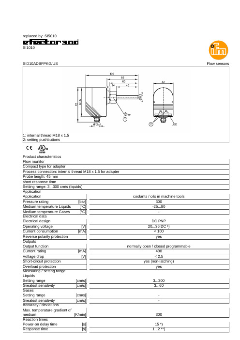
replaced by:SI5010SI1010Flow sensorsSID10ADBFPKG/US1:internal thread M18x 1.52:setting pushbuttonsProduct characteristics Flow monitorCompact type for adapterProcess connection:internal thread M18x 1.5for adapter Probe length:45mm short response timeSetting range:3...300cm/s (liquids)Application coolants /oils in machine toolsApplication 300Pressure rating [bar]-25 (80)Medium temperature Liquids [°C]-Medium temperature Gases [°C]Electrical data DC PNP Electrical design 20...36DC ¹)Operating voltage [V]<100Current consumption [mA]yesReverse polarity protection Outputsnormally open /closed programmableOutput function 400Current rating [mA]<2.5Voltage drop [V]yes (non-latching)Short-circuit protection yesOverload protectionMeasuring /setting range Liquids3...300Setting range [cm/s] 3...60Greatest sensitivity [cm/s]Gases-Setting range [cm/s]-Greatest sensitivity [cm/s]Accuracy /deviations300Max.temperature gradient of medium [K/min]Reaction times15*)Power-on delay time [s] 1...2**)Response time [s]Software /programmingpushbuttons Adjustment of the switch point Environment-25...80Ambient temperature [°C]IP 67ProtectionTests /approvals Shock resistance 50g (11ms)DIN IEC 68-2-27:Vibration resistance 20g (55...2000Hz)DIN EN 60068-2-6258MTTF [Years]Mechanical data internal thread M18x 1.5for adapterProcess connection stainless steel 316L /1.4404;O-ring:FKM 8x 1.5gr 80°Shore AMaterials (wetted parts)PBT-GF 20Housing materials 45Probe length L [mm]0.292Weight [kg]Displays /operating elements 10LEDs,three-colourFunction display LED Electrical connection M12connectorConnectionWiringP =programming wire (for remote adjustment)Remarks Remarks¹)to EN50178,SELV,PELV *)optically indicated**)for a temperature gradient of 1K/min1Pack quantity [piece]ifm efector,inc.•1100Atwater Drive •Malvern •PA 19355—We reserve the right to make technical alterations without prior notice.—US —SI1010—10.07.2013replaced by:SI5010SI1010-Flow monitor -eclass:27273101/27-27-31-01。
E+H流量计说明书
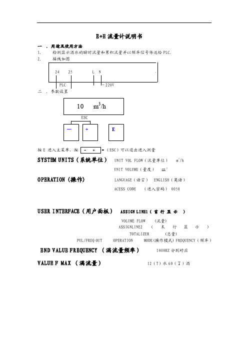
E+H 流量计说明书一 .用途及使用方法 1. 检测显示酒水的瞬时流量和累积流量并以频率信号传送给PLC. 2. 接线如图24 25 L NPLC ~220V 二 .参数设臵按E 进入主菜单,按ESC )可以退出进入测量SYSTEM UNITS (系统单位) UNIT VOL FLOW (流量单位) m 3/hUNIT VOLUME (量度) m3OPERATION (操作) LANGUAGE (语言) ENGLISH (英语)ACESS CODE (进入密码) 0050USER INTERFACE (用户面板) ASSIGN LINE1( 首 行 显 示 )VOLUME FLOW (流量)ASSIGNLINE2(末行显示)TOTALIZER (总量)PUL/FREQ OUT OPERATION MODE(操作模式) FREQUENCY (频率)END VALUE FREQUENCY (满流量频率) 1000HZ 分别对应 VALUE F MAX (满流量) 12(T )水60(T)酒二、安装1.安装位臵只有当满管时才能获得准确的测量,要避免以下安装位臵:(1)管道最高点(易聚积气泡);(2)直接向下的管线的敞开出口前;(3)泵的入口侧(防止抽压而造成的对流量管衬里的破坏);(4)有残渣聚积的场合和排水管的最低点(最好安装一个清洁阀)。
2.安装方位最适宜的方位可帮助避免气体的累积和测量管内的残渣存积。
垂直安装、流体自下而上的安装位臵为最佳方位。
若为水平安装,测量电极平面必须水平,这样可以防止由于夹带的气泡而产生的电极短时间绝缘。
空管检测功能仅当测量装臵为水平安装及变送器外壳向上时能正确工作。
3.振动如果振动剧烈,注意支撑管道和传感器;若振动非常剧烈应将传感器和变送器分开安装。
不允许利用外框承住传感器的重量,这会使外框变形并破坏内部励磁线圈。
4.出入口直管段安装传感器时要尽量避免阀门、三通、弯头等组件,与他们之间的距离应能保证所需的进口和出口直管段以确保测量精度:入口长度≥5DN,出口长度≥2DN。
浙江浙大中控信息技术 VTD系列 视频交通流检测系统 说明书

结合虚拟线圈和跟踪功能的视频检测系统V T D系列视频交通流检测系统中控简介浙江浙大中控信息技术有限公司(以下简称“中控信息”)创建于1999年,是中控科技集团有限公司的重要组成部分。
中控信息凭借浙江大学多学科的综合优势,依托工业自动化国家工程研究中心、工业控制技术国家重点实验室和浙江大学先进控制研究所,并以自身雄厚的科研实力,致力于为交通、环保、建筑等公用工程行业提供一流的具有国际竞争力的技术、产品和解决方案。
随着我国经济的发展和居民汽车拥有量的快速提高,交通出行面临着严重拥堵、机动车行驶速度缓慢、出行时间延长和环境污染加重等问题。
而智能交通系统(简称ITS)是采用信息技术、计算机技术、控制技术等多种高新技术与传统交通运输方式相融合的集成和应用,是集高新技术的开发、集成、产业化和推广应用为一体的系统工程。
智能交通已逐步得到社会各界的广泛关注,并已成为交通领域的研究热点,社会各界对通过智能交通系统建设,缓解日益严重的交通问题寄予了厚望。
交通信息采集是当前智能交通系统应用的瓶颈之一,视频检测设备是交通信息采集的重要手段,对促进智能交通系统的发展和建设具有十分重要的作用。
VTD系列视频检测器是中控信息开发的具有完全自主知识产权、自有核心技术的基于高速DSP的嵌入式视频检测器产品,具有非接触式检测、设置方便、功能强大、性能可靠等优点。
系统简介SUPCON VTD 系列视频交通流检测系统采用最新高速DSP硬件平台和嵌入式软件系统,是专为各种交通流检测应用设计的专业视频检测系统。
系统采用工业标准机架式设计,每个机架可插入4块或8块视频检测卡,每块视频检测卡可独立处理一路视频信号,最多可检测双向八车道的交通流信息。
用户可在本地或远程网络上,以图形交互方式,通过上位机界面定义虚拟线圈和检测区,并根据需要进行配置后下载。
系统能够实时检测和计算出交通流参数和事件报警信息,并存储在内部数据存储器中或根据需要把数据传输到监控中心。
电磁流量测量系统Promag50 53P 说明书
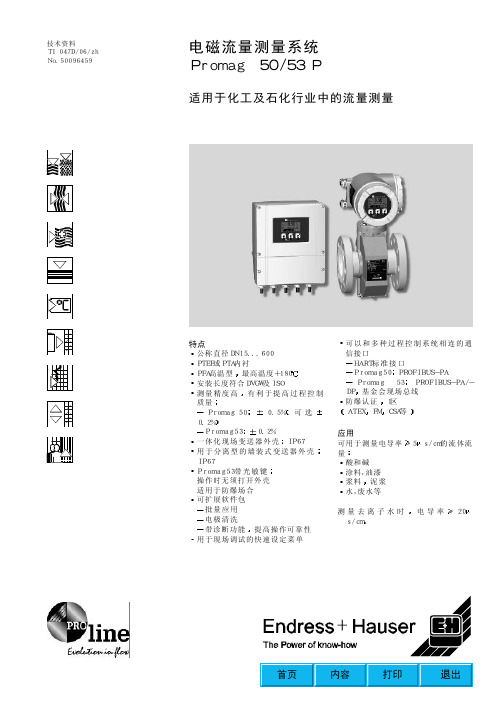
技术资料TI047D/06/zhNo.50096459HART标准接口PROFIBUS-PAPROFIBUS-PA/-DP防爆认证ATEXCSA等5涂料,油漆泥浆电导率s/cm公称直径DN15...600PFA高温型测量精度高可选一体化现场变送器外壳用于分离型的墙装式变送器外壳Promag53带光敏键可扩展软件包电极清洗提高操作可靠性测量原理法拉弟电磁感应定律证明一个导体在磁场中运动将感应生成一个电势流体就是运动中的导体然后变送器将它进行放大恒定的磁场由极性交替变化的开关直流电流所产生UeIVBILvUe=感应电势B=磁场强度L=电极距离v=流速Q=体积流量A=管道横截面I=电流强度有两种型号可选一体化分离型按键操作光敏键操作四行显示测量变量测量范围量程比输入信号输出信号报警信号负载流速V=0.01...10m/s带指定测量精度R=5K电气隔离可设置为测量值抑制批量起始/暂停有源/无源可选分辨率A有源Ri0/4...20mA150Umax=30VDC有源/无源可选时间常数可选满量程值可选0.005%o.r./分辨率A0/4...20mA700R)4...20mARi无源30VDC电气隔离频率输出开关比1:1脉冲值和脉冲极性可选最大脉冲频率可选有源/无源可选时间常数可选温度系数0.5有源R(HART250无源max.30VDC150电气隔离24VDC100无源30VDC满量程频率2...10000Hz(f=12500Hz)脉冲宽度max.10s脉冲输出脉冲宽度可设定开关比1:1故障响应可选故障响应可选Promag50故障或电源故障时断开Promag53故障或电源故障时处于失电状态参见仅指Promag53)Promag50电流输出Promag53电流输出输入变量输出变量开关输出小流量切除电气隔离状态输出max.30VDC/250mA故障信息EPD流向Promag53)常闭或常开触点可选继电器1=NOmax.30V/0.5AAC电气隔离可设置为空管检测限位值输出和供电回路相互电气隔离供电A=A向视图墙装式变送器外壳85...260VAC16...62VDC端子No.1L+对DC端子No.2L-对DCb.信号电缆见P5c.电源线接地端子d.信号电缆屏蔽层接地端子电气连接测量单元AABBaaccbbdd112220202121222223232424252526262727N(L-)L1(L+)Promag50端子分配Promag53端子分配根据不同的订货要求也可以是可变的可作为附件订货HART标准为了保证测量精度传感器和介质必须有相同的电势如果介质在无衬里并接地的金属管中流动就能满足接地要求注意应安装接地环电气连接分离型接地n.c.=电缆屏蔽层悬空S1E1E1E2E2S2GNDGNDEESEPD空管检测EPD空管检测线圈线圈424165843736424157737n.c.n.c.n.c.4无接地金属管道的接地为了避免测量误差变送器或传感器外壳接地注意300并用螺钉固定DN接地电缆直接连接到传感器金属支架上6mmCu2DN350塑料管道及带内衬管道的接地如果管道材质为非导体从而损坏参考电极时这种特殊情况包括那些带绝缘内衬的管道系统及由玻璃纤维或PVC制成的管道电化学腐蚀引起损坏应注意这两种材质的电化学特性阴极保护测量管必须按下述方式接地安装测量管时铜线6mm保证当采用螺钉紧固装置时2a=隔离变压器6mmCu2abb6mmCu2电源和信号电缆电缆入口M20电缆入口Pg13.5(5...15mm)NPT分离型连接电缆1.5(8...12mm)//27mm)/Km芯/芯持久工作温度信号电缆0.38mmPVC电缆带普通铜网屏蔽层空管检测0.38mmPVC电缆带普通铜网屏蔽层电阻50电容持久工作温度在有强烈电子干扰的区域内测量管应遵守EN61010将壳体内的接地端子接地85...260VAC45...65Hz16...62VDCAC15VADC15W启动电流max.13.5A(max.3A(EEPROM或T-DAT贮存测量值公称直径标定因子参考条件测量误差符合DIN19200和VDI/VDE2641介质温度环境温度预热时间10出口直管段DN传感器处于管道中心位置Promag50:脉冲输出:1mm/s(o.r.=满量程读数的)电流输出:附加APromag53:脉冲输出:2mm/s(o.r.=满量程读数的)电流输出:附加A在指定的范围内电源电压波动不影响测量0.1%o.r.o.r.=满量程读数的%o.r.[%]2.52.01.51.00.5001246810v[m/s]0.5%0.2%安装位置只有当满管时才能进行正确的测量易积聚气泡hDN以避免抽压时损坏测量管内衬隔膜泵或柱塞泵时需要安装脉冲节气阀非满管时倾斜非满管的管道需加泄放口EPD检测管道是否充满有残渣积聚场合建议安装清洁DNDN向下管道当向下管道长度超过5m时ba以避免低压时损坏测量管内衬减少含气量bb=虹吸管方位最佳安装方位有助于避免测量管内气体累积和残渣存积为了正确测量某些特殊的介质ECC用于易粘附的介质EPD或者在过程压力波动的场合垂直安装并可不加空管检测电极测量电极平面必须水平注意1=EPD电极2=测量电极3=参考电极1232AA振动如果振动剧烈注意抗振动和抗冲击性能指标请查P16>10m支撑如果公称直径DN变送器应安装在能够承受足够负载的基座上不允许利用外框承受传感器的重量入口和出口直管段如果可能三通满足下列进口和出口直管段要求以确保测量精度进口直管段DN2DNDN缩径管和扩大管对于流动较慢的液体这里所示的图表可以用来计算缩径和扩径引起的压力损失1.计算直径比d/D2.从图上可以读出对应于流速和d/D的压损值max.4为了保证测量精度电缆的移动会引起测量信号的失真不要将电缆敷设在电器设备和开关柜旁确保传感器和变送器之间电势相等环境温度贮存温度保护等级抗冲击性和抗震性电磁兼容性连接电缆长度允许电缆长度Lmax取决于介质的电导率最小电导率为20S/cm]-20...+60传感器注意以下事项在阴暗处安装尤其在气候温暖的地区变送器安装应该远离传感器(介质温度范围(+20IP67变送器和传感器IP68PromagP传感器符合IEC68-2-6符合EN61326及NAMUR推荐NE21操作条件(环境条件)介质温度范围允许介质温度取决于测量管内衬材质PTFE(DN15...600)PFA(DN25...200)详见曲线图一体化型T=环境温度带绝缘AF操作条件(过程条件)电导率最小电导率s/cm20去离子水注意最小电导率也受连接电缆的长度影响连接电缆长度分离型T=环境温度带绝缘AFT[]A60402006040200HTHTT[]F-20-20002020404060608080100100120120140140160160180180介质压力范围DIN2501DN200...600DN65...600DN200...600DN15...150Class150(1/2...24")Class300(1/2...12")JISB2238DN50...300DN15...300最合适的流速为2...3m/s2m/s例如陶粘土矿浆等2m/s例如废水污泥等压力损失没有压损缩径管机械结构设计/尺寸墙装式变送器外壳重量PromagP/DN25324050658010012515020025030020020020020020020025025030035045050034134134134139139139147247252757762725725725725728228228232232234737239784848484109109109150150180205230120120120120180180180260260324400460949494949494941401401561561667.38.09.410.612.014.016.021.525.535.348.557.51"-1/"2"-3"4"-6"8"10"12"12ANSI[inch]LABCKE重量[mm][mm][mm][mm][mm][mm][kg]227207K187168EL(DVGW)PromagP/DN墙装式变送器外形尺寸PromagP/DN350400450500600550600650650780738.5790.5840.5891.5995.5456.5482.5507.5533.0585.0282.0308.0333.0358.5410.556461666671782127627629229240211013024017023014"16"18"20"24"ANSI[inch]LABCKE重量[mm][mm][mm][mm][mm][mm][kg]227207K187168ELPromagP/DN墙装式变送器外形尺寸重量见P19材质变送器外壳粉末压铸铝或不锈钢铸铝传感器外壳粉末压铸铝涂层钢法兰材质SS1.4571ANSI316LS20C1.4435哈氏C-22遵循DIN2690标准材料负载曲线法兰材质DIN2413ArraySS1.4571法兰标准2505法兰材质ANSIB16.5法兰材质ANSIB16.5法兰材质AWWAC207电极过程连接法兰材质JISB2238测量1.4435钽参考电极和EPD电极为铂/铑80/20法兰标准ANSI液晶显示两行Promag53)用户可设置需显示的不同的测量值和状态变量两种类型的变送器有统一的操作方式-E快速设定菜单直接调试Promag53用三个光敏键+就地操作PROFIBUS-PA协议Promag53远程通信遵循HART基金会现场总线协议显示和用户接口操作远程通信Ex认证CE认证其他标准及指南现有的Ex认证证书可根据需要从E+H销售部门得到测量系统遵循CE认证EN60529外壳防护等级EN61010对电器设备的测量调节及试验程序的保护测量EN61326电磁兼容性NAMURNE21化学工业控制和标准规范协会证书及认证SI028D/06/enPromag50/53W技术样本TI048D/06/enPromag50操作手册BA047D/06/en和BA048D/06/en有关防爆的资料FM用于变送器和传感器的所有附件E+H服务机构可根据需要提供详细的信息PFA可达+180不适于防爆场合DIN2501B16.510KJISB2238Tantalum测量电极标准型欧洲隔爆Div.177墙装式7铝外壳8墙装式8铝外壳M20用于非防爆场合带显示带显示不能用于防爆场合具有很强的抗腐蚀能力PFA可达+180不适于防爆场合2501B16.5JISB2238Tantalum测量电极标准型欧洲隔爆Div.16767墙装式67铝外壳68墙装式68铝外壳M20用于非防爆场合带显示带显示不适用于防爆场合请将各选项中所需功能的相应字母填在相应空格中。
流量检测系统方案
流量检测系统方案一、引言随着互联网的迅猛发展和普及,网络流量逐渐成为了重要的信息资源。
为了改善网络管理和提高网络性能,流量检测系统应运而生。
流量检测系统能够帮助网络管理员监控网络流量的使用情况,并提供详细的流量统计信息,以便对网络进行优化和改进。
本文将介绍一个流量检测系统的方案。
二、目标与需求分析1.目标2.需求分析(1)实时监测网络流量:系统应能够实时监测网络流量,包括入站流量和出站流量。
(2)流量分类和标记:系统应能够对流量进行分类和标记,以便对不同类型的流量进行不同的管理和优化。
(3)流量统计和分析:系统应能够对网络流量进行统计和分析,提供流量的总量、峰值、平均值等统计指标,并对流量进行可视化展示。
(4)异常流量检测:系统应能够检测到异常的网络流量,如DDoS攻击、流量突增等,以及对异常流量进行警报和处理。
(5)用户行为分析:系统应能够分析用户的网络行为,如访问量、访问频率、访问时长等,以帮助网络管理员监控用户行为和优化网络资源。
三、系统设计1.系统架构(1)数据采集模块:负责从网络设备或流量镜像端口中采集网络流量数据,包括数据包的头部信息、协议类型、流量大小等。
(2)数据处理模块:负责对采集到的流量数据进行解析、分类和标记,并将流量数据存储到数据库中。
(3)数据存储模块:负责存储流量数据,并提供对流量数据的快速查询和访问接口。
(4)数据分析模块:负责对存储的流量数据进行统计和分析,并生成统计报告和可视化展示。
(5)异常检测模块:负责检测异常流量,并对异常流量进行警报和处理。
2.数据采集与处理数据采集模块通过网络设备或流量镜像端口采集网络流量数据,并将采集到的流量数据传递给数据处理模块进行解析和处理。
数据处理模块对流量数据进行分类和标记,并将流量数据存储到数据库中。
3.数据存储与管理数据存储模块将流量数据存储到数据库中,并提供对流量数据的快速查询和访问接口。
为了提高查询和访问的效率,可以采用合适的数据库技术,如数据库分片、索引优化等。
流量监测设备Flowphant T DTT31、DTT35 说明书
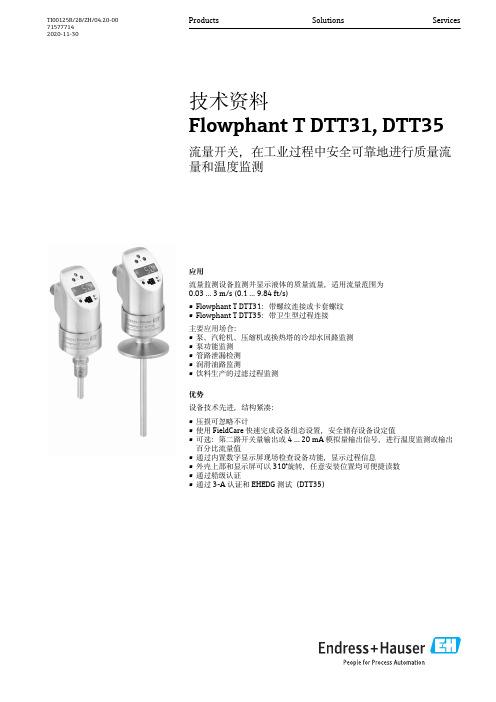
应用流量监测设备监测并显示液体的质量流量,适用流量范围为0.03 … 3 m/s (0.1 … 9.84 ft/s)•Flowphant T DTT31:带螺纹连接或卡套螺纹•Flowphant T DTT35:带卫生型过程连接主要应用场合:•泵、汽轮机、压缩机或换热塔的冷却水回路监测•泵功能监测•管路泄漏检测•润滑油路监测•饮料生产的过滤过程监测优势设备技术先进,结构紧凑:•压损可忽略不计•使用FieldCare 快速完成设备组态设置,安全储存设备设定值•可选:第二路开关量输出或4 … 20 mA 模拟量输出信号,进行温度监测或输出百分比流量值•通过内置数字显示屏现场检查设备功能,显示过程信息•外壳上部和显示屏可以310°旋转,任意安装位置均可便捷读数•通过船级认证•通过3-A 认证和EHEDG 测试(DTT35)Products Solutions Services技术资料Flowphant T DTT31, DTT35流量开关,在工业过程中安全可靠地进行质量流量和温度监测TI00125R/28/ZH/04.20-00715777142020-11-30Flowphant T DTT31, DTT352Endress+Hauser目录功能与系统设计 (3)测量原理...................................3测量系统.. (3)输入 (5)测量变量...................................5测量范围.. (5)输出.....................................5输出信号...................................5报警信号...................................5最大负载...................................5调节范围...................................5开关容量...................................5感性负载...................................5电源 (6)电气连接...................................6供电电压...................................7电流消耗.. (7)性能参数 (7)参考操作条件................................7最大测量误差................................7开关点的非重复性............................9温度差....................................9传感器的响应时间............................9长期漂移...................................9长期可靠性.................................9开关量输出的响应时间.........................9模拟量输出.................................9安装 (10)安装方向..................................10安装指南..................................10前后直管段.. (11)环境条件 (12)环境温度范围...............................12储存温度..................................12海拔高度..................................12防护等级..................................12抗冲击性..................................12抗振性...................................12电磁兼容性(EMC)..........................12电气安全性................................12过程条件 (12)过程温度范围...............................12过程压力范围...............................13流速限制..................................13工作范围..................................13机械结构 (13)设计及外形尺寸.............................13DTT31 的设计及过程连接外形尺寸. (13)DTT35的设计及过程连接外形尺寸................14重量.....................................15材质. (15)可操作性 (16)操作方式..................................16现场操作..................................16通过个人计算机进行远程操作.. (18)证书和认证 (19)CE 认证...................................19其他标准和准则.............................19UL 认证...................................19卫生型认证................................19与食品/产品接触的材质(FCM).................19船级认证..................................19材料证书..................................19订购信息.................................19附件....................................20设备专用附件...............................20通信专用附件. (21)补充文档资料 (22)技术资料..................................22操作手册. (22)Flowphant T DTT31, DTT35功能与系统设计测量原理设备基于热式原理测量液体的质量流量。
Proline Promag 10L 电磁流量测量系统说明书

TI00100D/28/zh/16.11技术资料Proline Promag 10L电磁流量测量系统水或污水测量场合中的液体流量测量应用电磁流量计可以进行液体的双向流量测量,被测液体的最小电导率应 50 μS/cm :•饮用水•污水•污泥•流量测量可达162,000 m³/h (731,000 gal/min)•流体温度可达+90 °C (+194 °F)•过程压力可达16 bar (232 psi)•装配长度符合DVGW/ISO 标准 (DVGW :德国气体与水协会)专用测量管内衬采用聚氨酯、硬橡胶或PTFE 材料,通过下列饮用水认证:•KTW •WRAS •NSF •ACS优势Promag 系列流量计可以在多种不同的过程条件下进行高精度测量,是一种经济的流量测量解决方案。
Proline 系列变送器具有下列优点:•高可靠性和高测量稳定性•统一的操作模式Promag 系列传感器经过多次试验和测试,具有下列优点:•无压损•抗振性强•安装和调试简便Proline Promag 10L2Endress+Hauser目录功能与系统设计 . . . . . . . . . . . . . . . . . . . . . . . . . . . . .3测量原理 . . . . . . . . . . . . . . . . . . . . . . . . . . . . . . . . . . . . . . . . . . 3测量系统 . . . . . . . . . . . . . . . . . . . . . . . . . . . . . . . . . . . . . . . . . . 3输入 . . . . . . . . . . . . . . . . . . . . . . . . . . . . . . . . . . . . . .3测量变量 . . . . . . . . . . . . . . . . . . . . . . . . . . . . . . . . . . . . . . . . . . 3测量范围 . . . . . . . . . . . . . . . . . . . . . . . . . . . . . . . . . . . . . . . . . . 3量程比 . . . . . . . . . . . . . . . . . . . . . . . . . . . . . . . . . . . . . . . . . . . . 3输出 . . . . . . . . . . . . . . . . . . . . . . . . . . . . . . . . . . . . . .4输出信号 . . . . . . . . . . . . . . . . . . . . . . . . . . . . . . . . . . . . . . . . . . 4报警信号 . . . . . . . . . . . . . . . . . . . . . . . . . . . . . . . . . . . . . . . . . . 4负载 . . . . . . . . . . . . . . . . . . . . . . . . . . . . . . . . . . . . . . . . . . . . . . 4小流量切除 . . . . . . . . . . . . . . . . . . . . . . . . . . . . . . . . . . . . . . . . . 4电气隔离 . . . . . . . . . . . . . . . . . . . . . . . . . . . . . . . . . . . . . . . . . . 4电源 . . . . . . . . . . . . . . . . . . . . . . . . . . . . . . . . . . . . . .4测量单元的电气连接 . . . . . . . . . . . . . . . . . . . . . . . . . . . . . . . . . 4接线端子分配 . . . . . . . . . . . . . . . . . . . . . . . . . . . . . . . . . . . . . . . 5分体式仪表的电气连接 . . . . . . . . . . . . . . . . . . . . . . . . . . . . . . . 5供电电压(电源) . . . . . . . . . . . . . . . . . . . . . . . . . . . . . . . . . . . . 5电缆入口 . . . . . . . . . . . . . . . . . . . . . . . . . . . . . . . . . . . . . . . . . . 5电缆规格(分体式仪表用) . . . . . . . . . . . . . . . . . . . . . . . . . . . . 6功率消耗 . . . . . . . . . . . . . . . . . . . . . . . . . . . . . . . . . . . . . . . . . . 6电源故障 . . . . . . . . . . . . . . . . . . . . . . . . . . . . . . . . . . . . . . . . . . 6电势平衡 . . . . . . . . . . . . . . . . . . . . . . . . . . . . . . . . . . . . . . . . . . 7性能参数 . . . . . . . . . . . . . . . . . . . . . . . . . . . . . . . . . . .8参考操作条件 . . . . . . . . . . . . . . . . . . . . . . . . . . . . . . . . . . . . . . . 8最大测量误差 . . . . . . . . . . . . . . . . . . . . . . . . . . . . . . . . . . . . . . . 8重复性 . . . . . . . . . . . . . . . . . . . . . . . . . . . . . . . . . . . . . . . . . . . . 8操作条件:安装 . . . . . . . . . . . . . . . . . . . . . . . . . . . . .9安装指南 . . . . . . . . . . . . . . . . . . . . . . . . . . . . . . . . . . . . . . . . . . 9前后直管段 . . . . . . . . . . . . . . . . . . . . . . . . . . . . . . . . . . . . . . . . 12连接管 . . . . . . . . . . . . . . . . . . . . . . . . . . . . . . . . . . . . . . . . . . . 13连接电缆长度 . . . . . . . . . . . . . . . . . . . . . . . . . . . . . . . . . . . . . . 14操作条件:环境 . . . . . . . . . . . . . . . . . . . . . . . . . . . .15环境温度范围 . . . . . . . . . . . . . . . . . . . . . . . . . . . . . . . . . . . . . . 15储存温度 . . . . . . . . . . . . . . . . . . . . . . . . . . . . . . . . . . . . . . . . . 15防护等级 . . . . . . . . . . . . . . . . . . . . . . . . . . . . . . . . . . . . . . . . . 15抗冲击性和抗振性 . . . . . . . . . . . . . . . . . . . . . . . . . . . . . . . . . . 15电磁兼容性(EMC) . . . . . . . . . . . . . . . . . . . . . . . . . . . . . . . . . . 15操作条件:过程 . . . . . . . . . . . . . . . . . . . . . . . . . . . .16介质温度范围 . . . . . . . . . . . . . . . . . . . . . . . . . . . . . . . . . . . . . . 16电导率 . . . . . . . . . . . . . . . . . . . . . . . . . . . . . . . . . . . . . . . . . . . 16介质压力范围 (标称压力) . . . . . . . . . . . . . . . . . . . . . . . . . . . 16密闭压力 . . . . . . . . . . . . . . . . . . . . . . . . . . . . . . . . . . . . . . . . . 16限流值 . . . . . . . . . . . . . . . . . . . . . . . . . . . . . . . . . . . . . . . . . . . 16压损 . . . . . . . . . . . . . . . . . . . . . . . . . . . . . . . . . . . . . . . . . . . . . 18机械结构 . . . . . . . . . . . . . . . . . . . . . . . . . . . . . . . . . .19设计及外形尺寸 . . . . . . . . . . . . . . . . . . . . . . . . . . . . . . . . . . . 19重量 . . . . . . . . . . . . . . . . . . . . . . . . . . . . . . . . . . . . . . . . . . . . . 30测量管规格 . . . . . . . . . . . . . . . . . . . . . . . . . . . . . . . . . . . . . . . 33材料 . . . . . . . . . . . . . . . . . . . . . . . . . . . . . . . . . . . . . . . . . . . . . 35材料负载曲线 . . . . . . . . . . . . . . . . . . . . . . . . . . . . . . . . . . . . . 35配套电极 . . . . . . . . . . . . . . . . . . . . . . . . . . . . . . . . . . . . . . . . . 37过程连接 . . . . . . . . . . . . . . . . . . . . . . . . . . . . . . . . . . . . . . . . . 37表面光洁度 . . . . . . . . . . . . . . . . . . . . . . . . . . . . . . . . . . . . . . . 37人机界面 . . . . . . . . . . . . . . . . . . . . . . . . . . . . . . . . . .37显示单元 . . . . . . . . . . . . . . . . . . . . . . . . . . . . . . . . . . . . . . . . . 37操作单元 . . . . . . . . . . . . . . . . . . . . . . . . . . . . . . . . . . . . . . . . . 37远程操作 . . . . . . . . . . . . . . . . . . . . . . . . . . . . . . . . . . . . . . . . . 37证书和认证 . . . . . . . . . . . . . . . . . . . . . . . . . . . . . . . .38CE 认证 . . . . . . . . . . . . . . . . . . . . . . . . . . . . . . . . . . . . . . . . . . 38C-Tick 认证 . . . . . . . . . . . . . . . . . . . . . . . . . . . . . . . . . . . . . . . 38饮用水认证 . . . . . . . . . . . . . . . . . . . . . . . . . . . . . . . . . . . . . . . 38其他标准和准则 . . . . . . . . . . . . . . . . . . . . . . . . . . . . . . . . . . . 38订购信息 . . . . . . . . . . . . . . . . . . . . . . . . . . . . . . . . . .38附件 . . . . . . . . . . . . . . . . . . . . . . . . . . . . . . . . . . . . .39文档资料 . . . . . . . . . . . . . . . . . . . . . . . . . . . . . . . . . .39注册商标 . . . . . . . . . . . . . . . . . . . . . . . . . . . . . . . . . .39Proline Promag 10LEndress+Hauser 3功能与系统设计测量原理根据法拉第电磁感应定律,导体在磁场中运动时,会产生感应电压。
流量检测器的说明书

ApplicationsFlow switch for monitoring and displaying the relative mass flow rates of liquid media in the range from 0.03 to 3 m/s (0.1 to 9.84 ft/s):•Flowphant T DTT31 − with threaded connections or compression fitting •Flowphant T DTT35 − with process connections for hygienic applications Applications:•Monitoring of cooling water circuits of pumps, turbines, compressors and heat exchangers•Monitoring of pump functions •Leak monitoring in process pipes •Monitoring of lubrication circuits•Filter monitoring in the beverages industry Your benefitsThe compact flow switch impresses with state-of-the-technology:•Virtually zero pressure loss•FieldCare for quick configuration and reliable storage of device settings •Optional: 4 to 20 mA analog output for outputting the flow as a percentage •Optional: second switch output or 4 to 20 mA analog output for temperature monitoring•Onsite function check and process information with digital display on device •Top housing section which can be rotated 310° and rotatable display mean measured values can be read in all installation positions •Marine approval•3-A mark and EHEDG certificate for DTT35Products Solutions ServicesTechnical InformationFlowphant T DTT31, DTT35Flow switchTI00125R/09/EN/03.18714155662018-02-15Flowphant T DTT31, DTT352Endress+HauserTable of contentsFunction and system design (3)Measuring principle ............................3Measuring system .. (3)Input (5)Measured variable .............................5Measuring range (5)Output (5)Output signal ................................5Signal on alarm ...............................5Load ......................................5Range of adjustment ...........................5Switching capacity .............................6Inductive load ................................6Power supply (6)Electrical connection ...........................6Supply voltage ...............................7Current consumption (7)Performance characteristics (7)Reference operating conditions ....................7Maximum measured error .......................7Switch point non-reproducibility ...................9Temperature gradient ..........................9Sensor response time ...........................9Long-term drift ...............................9Long-term reliability ...........................9Switch output response time ......................9Analog output ...............................9Installation (10)Orientation ................................10Installation instructions ........................10Inlet and outlet runs ..........................11Environment (12)Ambient temperature range .....................12Storage temperature ..........................12Degree of protection ..........................12Shock resistance .............................12Vibration resistance ...........................12Process (12)Process temperature range ......................12Process pressure range .........................12Flow limit .................................12Operational range ............................12Mechanical construction ....................13Design, dimensions ...........................13DTT31 design, dimensions of the process connections ....13DTT35 design, dimensions of the process connections ....14Weight ...................................14Materials ..................................14Operability (16)Operating concept ............................16Local operation ..............................16Remote operation with PC .. (18)Certificates and approvals (19)Electromagnetic compatibility (EMC)...............19Hygiene standard ............................19Parts in contact with medium ....................19Marine approval .............................19Other standards and guidelines ...................19Material certification ..........................19Ordering information .......................19Accessories . (20)Device-specific accessories ......................20Communication-specific accessories ................21Supplementary documentation (23)Technical Information .........................23Operating Instructions .........................23Flowphant T DTT31, DTT35Endress+Hauser 3Function and system designMeasuring principleThe device measures the mass flow of a liquid medium using the calorimetric measurement method.The calorimetric measuring principle is based on the cooling of a heated temperature sensor. Heat is removed from the sensor by forced convection due to medium flowing by. The extent of this heat transfer depends on the flow velocity of the medium and the difference in temperature between the sensor and the medium (King's Law). The higher the flow velocity or the mass flow of the medium,the greater the temperature sensor cooling.Measuring systemOverviewFlowphant T DTT31, DTT354Endress+HauserDC voltage version (DC)PNP switch output of electronics.Power supply e.g. with a power supply unit.Preferably in connection with programmable logic controllers (PLC) or for controlling a relay.A 1x PNP switch outputB 2x PNP switch outputC PNP switch output with additional analog output 4 to 20 mA(active)1Transmitter power supply unit, e.g. RNB1302Load (e.g. programmable logic controller, process control system, relay)3Display unit e.g. RIA452 or recorder e.g. Ecograph T or Minilog B (at 4 to 20 mA analog output)1 "Easy Analog RNB130" transmitter power supply unit:Primary switched-mode power supply for sensors. Space-saving DIN rail mounting as per IEC 60715.Wide-range input: 100 to 240 V AC nominal voltage; output: 24 V DC , max. 30 V in the event of an error;Nominal current: 1.5 A. Connection to single-phase alternating current networks or to two phase conductors of three-phase supply networks.2 process display units RIA452:If you would like to read off the instantaneous temperature value not only locally, but also directly from a control room or in the PC network, for example, the process display unit RIA452 is one possible solution: Digital process display unit in 96 to 96 mm (3.78 to 3.78 in) panel mountedFlowphant T DTT31, DTT35Endress+Hauser 5housing for monitoring and displaying analog measured values with pump control and batchfunctions. Multicolored 7-digit 14-segment LC display with bargraph representation. Configuration and measured value visualization via RS232 interface and PC configuration software.3 Universal Graphic Data Manager Ecograph T, data logger Minilog B:If you would not only like to read off the instantaneous temperature value, but also record, analyze and display it directly in a control room or in the PC network, for example, then the following options are available:•Universal Graphic Data Manager Ecograph T in 144 mm (5.67 in) x 144 mm (5.67 in) panelmounted housing for the electronic capture, display, recording,analysis, remote transmission and archiving of analog and digital input signals. Multichannel data recording system withmulticolored TFT display (145 mm (5.7 in)) screen size), galvanically isolated universal inputs (U,I, TC, RTD, pulse, frequency), digital inputs, transmitter power supply, limit relays, communication interfaces (USB, Ethernet, optionally RS232/485), 128 MB internal memory, external SD card and USB stick. The Field Data Manager (FDM) software supports data analysis at the PC, the device can be configured with FieldCare or the integrated Web server.•Data logger Minilog B measured value recorder with 2 input channels for recording and storing analog and digital values. Internal 128 kB memory for max. 84 000 measured values.Configuration and measured value visualization via RS232 interface and PC configuration software. Optionally available with telealarm function.InputMeasured variable•Flow velocity of liquid media (calorimetric measuring principle)•Temperature (RTD), optionally for two switch outputs or additional analog outputMeasuring rangeFlow 0.03 to 3 m/s (0.1 to 9.84 ft/s), as relative value between 0 to 100%; maximum display resolution: 1%Temperature–20 to +85 °C (–4 to +185 °F); display resolution: 1 °C (1 °F)OutputOutput signalDC voltage version (short-circuit proof version):•1x PNP switch output (flow) or•2x PNP switch outputs (flow or temperature, configurable) or•1x PNP switch output and 1x 4 to 20 mA output, active (flow or temperature, configurable)The analog output reports the measured flow as a relative value expressed as a percentage of the set measuring range.Signal on alarmAnalog output: signal on alarm according to NAMUR NE43Underranging Linear drop to 3.8 mA OverrangingLinear rise to 20.5 mASensor breakage; sensor short-circuit ≤3.6 mA or ≥ 21.0 mA (output 21.7 mA is guaranteed for setting ≥ 21.0 mA)Switch outputsIn the safe state (switch open)LoadMax. (V power supply - 6.5 V) / 0.022 A (current output)Range of adjustmentSwitch output Switch point (SP) and switchback point (RSP) in increments of 1% with min.hysteresis of 5%Damping User-configurable 0 = off (no damping) or 10 to 40 s in increments of 1 s Unit%, optionally °C, °F (with two outputs and temperature monitoring)Flowphant T DTT31, DTT356Endress+HauserSwitching capacity DC voltage version:Switch status ON Ia ≤ 250 mA Switch status OFF Ia ≤ 1 mA Switching cycles > 10,000,000Voltage drop PNP ≤2 VOverload protectionSwitching current checked automatically; switched off in event of overcurrent,switching current checked again every 0.5 s; max. capacitive load: 14 µF for max.supply voltage (without resistive load); periodic disconnection from a protective circuit in event of overcurrent (f = 2 Hz) and "Warning" displayedInductive loadTo prevent electrical interference, only operate an inductive load (relays, contactors, solenoid valves)with a direct protective circuit (free-wheeling diode or capacitor).Power supplyElectrical connectionPlug connectorA M12x1 connectorB Valve connector M16x1.5 or NPT ½"Device connectionDC voltage version with M12x1 connector1Flowphant T with M12x1 connectorFlowphant T DTT31, DTT35Endress+Hauser 7DC voltage version with M16x1.5 valve connector or NPT ½"Supply voltage DC voltage version: 18 to 30 V DC (reverse polarity protection)Behavior in the event of overvoltage (>30 V)•The device works continuously up to 34 V DC without any damage•No damage in event of transient overvoltage up to 1 kV (according to EN 61000-4-5)•If the supply voltage is exceeded, the specified characteristics are no longer guaranteed Behavior in the event of undervoltageIf the supply voltage falls below the minimum value, the device switches off in a defined manner (status as if not supplied with power = switch open)Current consumption < 100 mA (no-load) at 24 V DC , max. 150 mA (no-load); with reverse polarity protectionPerformance characteristicsThe percentage information in the "Performance characteristics" section refers to the full scale value or the set maximum value (100% value) of the monitoring range.Reference operating conditionsAs per DIN IEC 60770 or DIN IEC 61003T = 25 °C (77 °F) ± 5 °C (9 °F)–Relative humidity 45 to 75%–Ambient air pressure 860 to 1 060 kPa (124 to 153 psi), water testing medium –Supply voltage U = 24 V DC Maximum measured errorFlowThe device records flow velocities relatively in relation to a set flow monitoring range (0 to 100 % as the display value). Absolute measurement of the flow velocity or the mass flow is not possible. The sensitivity of the calorimetric flow sensor changes with the flow velocity of the medium. It increases with decreasing flow velocity (example: in the case of water, the greatest sensor sensitivity is in the range from 0.03 to 0.5 m/s).Flowphant T DTT31, DTT358Endress+Hauser2Standard characteristicA, B Configured flow monitoring ranges (example)LOWF 0%: Setting for the minimum flow velocity occurring in monitoring range A or B (0% value)HIF 100%: Setting for the maximum flow velocity occurring in monitoring range A or B (100% value)Temperature•Accuracy2 K (3.6 °F)•Reproducibility1 K (1.8 °F)•Influence of ambient temperature 0.05%/K of full scale valueFlowphant T DTT31, DTT35Endress+Hauser 9Switch point non-reproducibilityThe values indicated only apply to the device itself without factoring in the temperature-dependent change in the thermophysical properties of the medium. For this reason, it is advisable to commission the device and set the switch points at the process temperature → 161)For a Reynolds number > 10,000Temperature gradientIf the medium experiences a temperature change of ≥ 0.5 K/min, temporary display drifts are possible which can exceed the specified non-reproducibility values of the switch point.Sensor response time 6 to 12 sLong-term drift < 0.5% per year under reference operating conditionsLong-term reliabilitySwitch output response time 100 msAnalog outputMaximum measured error Switch point and display deviation + 0.1%Rise time t 90≤200 ms Settling time t 99≤500 msFlowphant T DTT31, DTT3510Endress+HauserInstallationOrientationNo restrictions. However, self-draining in the process must be guaranteed. If there is an opening to detect leaks at the process connection, this opening must be at the lowest possible point.•The display can be rotated electronically by 180 °.•The top housing section can be rotated mechanically by up to 310 °.6Installation in hygienic processesA Sanitary connection according to DIN 11851 (PL, PG, PH connection), only in conjunction with EHEDG-certified and self-centering sealing ring as per EHEDG position paperB Varivent and APV-Inline (LB, LL, HL connection)CClamp according to ISO 2852 (DB, DL connection), only in conjunction with seal as per EHEDG position paperThe following action must be taken if a sealing ring (O-ring) or seal fails:•Remove the thermometer, clean the thread and the O-ring joint/sealing surface •Replace the sealing ring or seal •Perform CIP after installationIn the case of weld-in connections, exercise the necessary degree of care when performing the welding work on the process side:•Suitable welding material•Flush-welded or with welding radius > 3.2 mm (0.13 in)•No recesses, folds or gaps•Honed and polished surface, Ra ≤ 0.8 mm (0.031 in)As a general rule, the thermometers should be installed in such a way that does not impact their ability to be cleaned (the requirements of the 3-A Standard must be observed). The Varivent® couplings enable flush-mount installation.Inlet and outlet runsThe thermal measuring principle is sensitive to disturbed flow conditions.•As a general rule, install the measuring device as far away as possible from any flow disturbances. For further information → ISO 14511.•If possible, install the sensor upstream from fittings such as valves, T-pieces, elbows etc.•To attain the specified level of accuracy of the measuring device, the inlet and outlet runs mentioned below must be maintained at the very minimum.•If several flow disturbances are present, maintain the longest specified inlet run.1Reduction 2Expansion390° elbow or T-piece 4Pump5Control valve62x 90° elbow, 2- or 3-dimensionalEnvironmentAmbient temperature range –40 to +85 °C (–40 to +185 °F)Storage temperature –40 to +85 °C (–40 to +185 °F)Degree of protectionIP65M16 x 1.5 or NPT ½", valve connector IP66M12 x 1 connectorShock resistance 50 g as per DIN IEC 68-2-27 (11 ms)Vibration resistance•20 g as per DIN IEC 68-2-6 (10-2000 Hz)•4 g as per marine approvalProcessProcess temperature range–20 to +85 °C (–4 to +185 °F)The sensor can be exposed to process temperatures up to 130 °C (266 °F) without being damaged.The monitoring system switches off automatically at T ≥ 85 °C (185 °F) and starts again at T ≤85 °C (185 °F).Process pressure rangeMaximum permissible process pressure P max ≤ 10 MPa = 100 bar (1 450 psi)The maximum process pressure for the conical metal-metal process connection (MB option) for the device is 1.6 MPa = 16 bar (232 psi).Flow limit Liquids: 0 to 3.0 m/s (0 to 9.84 ft/s)Operational rangeLiquids: 0.03 to 3.0 m/s (0.1 to 9.84 ft/s)Mechanical constructionAll dimensions in mm (in)L = insertion lengthM12x1 connector as per IEC 60947-5-2Valve connector M16x1.5 or NPT ½" as per DIN 43650A/ISO 44007Process connection versions8Process connection versionsAll dimensions in mm (in).L = insertion length LWeight Approx. 300 g (10.58 oz), depends on process connection and sensor length Materials•Process connection AISI 316L–Surfaces in contact with the process in hygienic version with surface quality Ra ≤0.8 µm (31.5 µin)–Coupling nut AISI 304•AISI 316L housing, with surface quality R a ≤ 0.8 µm (31.5 µin)O-ring between housing and sensor module: EPDM•Electrical connection–M12 connector, exterior AISI 316L, interior polyamide (PA)–Valve connector, polyamide (PA)–M12 connector, exterior 316L–Cable sheath polyurethane (PUR)–O-ring between electrical connection and housing: FKM•Display, polycarbonate PC-FR (Lexan®)Seal between display and housing: SEBS THERMOPLAST K®•Keys, polycarbonate PC-FR (Lexan®)OperabilityOperating concept Position of the display and operating elementsLocal operation Menu-guided operation using operating keys.Operation, visualization and maintenance with PC and FieldCare PC configuration software.Remote operation with PC1PC with FieldCare configuration software2Configuration kit TXU10-AA or FXA291 with USB port3Flow switchIn addition to the operating options listed in the previous "Onsite operation" section, furtherinformation about the Flowphant T is available via the FieldCare configuration software:Certificates and approvalsElectromagnetic compatibility (EMC)EMC to all relevant requirements of the IEC/EN 61326-series and NAMUR Recommendation EMC (NE21). For details, refer to the Declaration of Conformity.Maximum fluctuations during EMC-tests: < 1 % of measuring span.Interference immunity to IEC/EN 61326-series, requirements for industrial areas Interference emission to IEC/EN 61326-series, electrical equipment Class BHygiene standard•EHEDG certification, TYPE EL CLASS I. Permitted process connections in accordance with EHEDG,see 'P rocess connections'section → 13•3-A Authorization No. 1144. 3-A Sanitary Standard. Permitted process connections in accordancewith 3-A, see also "Process connections" section•3-A marked process connections → 14Parts in contact with medium The thermometer parts in contact with the medium meet the following European regulations:•(EC) No. 1935/2004, Article 3, Paragraph 1, Articles 5 and 17 on materials and articles intendedto come into contact with food.•(EC) No. 2023/2006 on good manufacturing practice (GMP) for materials and articles intended tocome into contact with food.•(EC) No. 10/2011 on plastic materials and articles intended to come into contact with food.•All surfaces in contact with the medium are free from materials derived from bovine animals orother livestock (ADI/TSE)Marine approval Information on the "Type Approval Certificates" currently available (DNVGL, BV, etc.) can be obtainedfrom the sales organization.Other standards and guidelines •IEC 60529Degrees of protection provided by enclosures (IP code)•IEC/EN 61010-1Protection Measures for Electrical Equipment for Measurement, Control, Regulation and Laboratory Procedures•NAMURInternational user association of automation technology in process industries (www.namur.de)•NEMAUnited States National Electrical Manufacturers Association.Material certification The material certificate 3.1 (according to standard EN 10204) can be requested separately. The"short form" certificate includes a simplified declaration with no enclosures of documents related tothe materials used in the construction of the individual sensor. It does, however, guarantee thetraceability of the materials through the identification number of the thermometer. The data relatedto the origin of the materials can subsequently be requested by the client if necessary.Ordering informationDetailed ordering information is available from the following sources:•In the Product Configurator on the Endress+Hauser website: -> Click "Corporate"-> Select your country -> Click "Products" -> Select the product using the filters and search field ->Open product page -> The "Configure" button to the right of the product image opens the ProductConfigurator.•From your Endress+Hauser Sales Center: Product Configurator - the tool for individual product configuration•Up-to-the-minute configuration data•Depending on the device: Direct input of measuring point-specific information such asmeasuring range or operating language•Automatic verification of exclusion criteria•Automatic creation of the order code and its breakdown in PDF or Excel output format•Ability to order directly in the Endress+Hauser Online ShopAccessoriesDevice-specific accessories Welding boss with sealing taperCollar welding bossWelding boss with sealing taper (metal-metal)Flowphant T DTT31, DTT35Endress+Hauser21Compression fitting1)SS316 clamping ring: can only be used once. Once released the compression fitting cannot be repositioned on the thermowell. Fully adjustable immersion length on initial installation2)PTFE/Silopren ® clamping ring: can be reused, once released the fitting can be moved up and down the thermowell. Fully adjustable immersion lengthCommunication-specific accessoriesCoupling; connecting cableFlowphant T DTT31, DTT3522Endress+Hauser4114.8(0.58)15Dimensions in mm (in)23Configuration kitConfiguration softwareThe FieldCare 'D evice Setup' configuration programs can be downloaded free of charge from the Internet at:/fieldcareFieldCare ’Device Setup’ can also be ordered from an Endress+Hauser sales office.Flowphant T DTT31, DTT35Endress+Hauser 23Supplementary documentationTechnical Information•Easy Analog RNB130: TI120R/09/en•Process display unit RIA452: TI113R/09/en•Universal data manager Ecograph T: TI01079R/09/en •Data logger Minilog B: TI089R/09/enOperating Instructions Flow switch Flowphant T DTT31, DTT35: BA00235R/09/en。
天清异常流量清洗系统 ADM-Guard Web 管理用户手册说明书
天清异常流量清洗系统A D M-G u a r d W e b管理用户手册北京启明星辰信息安全技术有限公司Beijing Venustech Cybervision Co., Ltd二零一二年五月版权声明北京启明星辰信息安全技术有限公司版权所有,并保留对本文档及本声明的最终解释权和修改权。
本文档中出现的任何文字叙述、文档格式、插图、照片、方法、过程等内容,除另有特别注明外,其著作权或其他相关权利均属于北京启明星辰信息安全技术有限公司。
未经北京启明星辰信息安全技术有限公司书面同意,任何人不得以任何方式或形式对本手册内的任何部分进行复制、摘录、备份、修改、传播、翻译成其它语言、将其全部或部分用于商业用途。
免责条款本文档依据现有信息制作,其内容如有更改,恕不另行通知。
北京启明星辰信息安全技术有限公司在编写该文档的时候已尽最大努力保证其内容准确可靠,但北京启明星辰信息安全技术有限公司不对本文档中的遗漏、不准确、或错误导致的损失和损害承担责任。
信息反馈如有任何宝贵意见,请反馈:信箱:北京市海淀区东北旺西路8号中关村软件园21号楼启明星辰大厦邮编:100193 电话:************传真:************您可以访问启明星辰网站:获得最新技术和产品信息。
目录第1章前言 (9)1.1 导言 (9)1.2 本书适用对象 (9)1.3 本书适合的产品 (9)1.4 手册章节组织 (9)1.5 相关参考手册 (10)第2章如何开始 (11)2.1 概述 (11)2.1.1 产品特点 (11)2.1.2 主要功能 (11)2.1.3 硬件描述 (13)2.1.4 软件描述 (15)2.1.5 附带软件描述 (16)2.2 拆箱检查 (16)2.3 安装 (16)2.3.1 检查安装场所 (16)2.3.2 安装 (17)2.3.3 网络连接 (17)2.4 配置管理方法 (17)2.4.1 网络接口WEB配置 (17)2.4.2 网络接口CLI配置 (17)2.4.3 本地串口CLI配置 (18)2.5 登录管理界面 (18)2.5.1 登录方法 (18)2.5.2 证书认证 (19)2.5.3 登录过程 (19)2.5.4 一般配置过程 (20)2.5.5 退出登录 (20)第3章系统管理 (22)3.1 系统信息 (22)3.1.1 版本信息 (22)3.1.2 License信息 (22)3.1.3 设备名称 (23)3.1.4 日期时间 (23)3.2 系统服务 (25)3.2.1 本地服务 (25)3.2.2 SSH服务 (26)3.2.3 Telnet服务 (28)3.2.4 SNMP配置 (29)3.2.5 WebUI超时 (31)3.3 配置管理 (31)3.3.2 存储设备管理 (32)3.3.3 当前配置查看 (33)3.4 维护升级 (33)3.4.1 系统升级 (33)3.4.2 License升级 (35)3.4.3 特征库升级 (35)3.5 证书管理 (36)3.5.1 导入证书 (36)3.5.2 本地证书 (37)3.5.3 CA中心 (42)3.6 集中管理 (45)3.7 批处理工具 (45)第4章网络管理 (46)4.1 网络接口 (46)4.1.1 接口IP地址 (46)4.1.2 接口配置 (51)4.2 ARP (56)4.2.1 静态ARP (56)4.2.2 ARP查看 (58)4.2.3 免费ARP (58)4.3 路由 (59)4.3.1 静态路由 (59)4.3.2 OSPF (62)4.3.3 智能路由 (65)4.3.4 路由表信息 (71)4.3.5 ISIS (71)4.4 DNS设置 (73)4.5 DHCP (74)4.5.1 服务器配置 (74)4.5.2 地址池配置 (75)4.5.3 DHCP中继 (78)第5章IPv6 (80)5.1 网络管理 (80)5.1.1 地址配置 (80)5.1.2 邻居配置 (81)5.1.3 服务段前缀 (81)5.1.4 自动配置 (82)5.1.5 静态路由 (82)5.2 资源定义 (83)5.2.1 地址 (83)5.2.2 服务 (85)5.2.3时间 (90)5.3 防火墙 (97)5.3.1 包过滤 (97)5.3.2 默认过滤策略 (97)5.4 流量牵引 (98)5.4.1 BGP牵引 (98)5.4.2 OSPF (109)5.5 流量分析 (110)5.5.1 自学习配置 (110)5.5.2 自学习管理 (112)5.6 流量清洗 (113)5.6.1 攻击处理方式 (113)5.6.2 日志采样 (114)5.6.3 DNS防护 (114)5.6.4 高级型攻击 (120)5.6.5 自定义特征 (124)5.7 流量统计 (126)5.7.1 事件统计 (126)5.7.2 攻击类型TOP5 (126)5.7.3 攻击来源TOP5 (127)5.7.4 攻击目的TOP5 (127)5.7.5 攻击流量统计 (128)5.7.6 保护域流量统计 (128)第6章虚拟网关 (130)6.1 网关管理 (130)6.1.1 虚拟网关划分 (130)6.1.2 接口归属查看 (132)6.2 全局资源 (132)6.2.1 地址 (132)6.2.2 服务 (137)6.2.3 时间 (142)6.2.4 应用协议 (145)6.2.5 包分类 (146)6.3 全局策略 (150)6.3.1 包过滤 (150)6.3.2 DNAT策略 (151)6.3.3 SNAT策略 (152)6.3.4 长连接 (154)第7章资源定义 (156)7.1 地址 (156)7.1.1 地址列表 (156)7.1.2 地址池 (157)7.1.3 地址组 (158)7.2 服务 (161)7.2.1 服务对象定义 (161)7.2.2 ICMP服务 (162)7.2.3 基本服务 (162)7.2.4 服务组 (164)7.2.5 ALG定义 (165)7.3 时间 (166)7.3.1 时间列表 (167)7.3.2 时间组 (168)7.4 应用协议 (169)7.4.1 应用协议 (169)7.4.2 应用协议组 (170)7.5 包分类 (170)第8章流量牵引 (174)8.1 BGP牵引 (174)8.1.1 BGP本地配置 (174)8.1.2 BGP邻居配置 (175)8.1.3 访问控制链表 (177)8.1.4 路由映射 (179)8.1.5 路由牵引配置 (181)8.2 OSPF (183)8.2.1 配置路由重分发 (183)8.2.2 启动、停止OSPF功能 (184)8.2.3 修改路由器ID (184)8.2.4 设置区域 (184)8.2.5 设置网络 (184)8.2.6 设置网络接口认证 (185)第9章流量分析 (186)9.1 自学习配置 (186)9.1.1 学习配置 (186)9.1.2 学习过程 (188)9.2 自学习管理 (188)9.2.1 学习结果 (188)9.2.2 学习曲线 (189)9.2.3 应用查看 (190)第10章流量清洗 (191)10.1 攻击处理方式 (191)10.2 日志采样 (191)10.3 攻击证据提取 (191)10.3.1 攻击证据提取 (191)10.3.2 捉包分析取证 (192)10.4 DNS防护 (193)10.4.2 域名访问限制 (195)10.4.3 DNS攻击保护 (197)10.4.4 域名长度参数 (199)10.5 基本型攻击 (199)10.6 高级型攻击 (200)10.7 自定义特征 (206)10.7.1 TCP (206)10.7.2 UDP (207)10.7.3 ICMP (207)10.7.4 自定义特征开启配置 (208)第11章流量回注 (209)11.1 接口转发 (209)11.2 启动GRE (211)11.3 隧道配置 (211)第12章流量统计 (213)12.1 事件统计 (213)12.1.1 开启统计 (213)12.1.2 事件统计 (213)12.2 攻击类型TOP5 (213)12.3 攻击来源TOP5 (214)12.4 攻击目的TOP5 (214)12.5 攻击流量统计 (215)12.5.1 即时流量统计 (215)12.5.2 异常流量统计 (215)12.6 保护域流量统计 (215)12.6.1 牵引流量统计 (215)12.6.2 清洗流量统计 (216)第13章防火墙 (217)13.1 包过滤 (217)13.1.1 默认过滤策略 (218)13.2 DNAT策略 (218)13.3 SNAT策略 (220)13.4 二层协议 (221)13.5 地址绑定 (222)13.6 服务器探测 (229)第14章会话管理 (232)14.1 会话配置 (232)14.2 长连接 (232)14.3 会话日志 (233)14.4 会话状态 (233)14.5 同步选项配置 (234)第15章带宽管理 (235)15.1 基于管道的带宽管理 (235)15.1.1 配置中心 (235)15.1.2 管道管理 (235)15.1.3 IP型策略管理 (236)15.1.4 动作管理 (237)15.2 基于接口的带宽管理 (238)15.2.1 物理限速 (238)15.2.2 QoS标签 (240)15.2.3 IPQoS (241)15.2.4 流量监管 (243)15.2.5 流量整形 (246)15.2.6 拥塞管理 (249)15.3 流量优化 (268)15.3.1 带宽借用 (268)15.3.2 流量建模 (271)第16章高可用性 (273)16.1 节点配置 (274)16.2 工作模式 (275)16.3 查看状态 (277)第17章应用安全 (278)17.1 DNS应用防火墙 (278)17.1.1 基本配置 (278)17.1.2 自定义域名监测 (279)17.1.3 静态域名表 (279)17.1.4 域名黑名单 (280)17.1.5 QPS信息 (282)17.1.6 重定向统计 (282)17.2 缓存感染监测 (283)17.2.1 缓存感染监测配置 (283)17.2.2 缓存感染实时监测统计 (283)17.2.3 缓存感染历史监测统计 (284)第18章应用识别 (285)18.1 特征策略 (285)18.2 策略应用 (288)18.3 统计图表 (290)18.4 日志采样 (290)第19章用户认证 (291)19.1 本地用户 (291)19.2 AAA认证 (292)19.2.1 认证服务器 (293)19.2.2 登录用户 (294)19.2.3 在线Portal用户 (294)19.2.4 Portal用户组 (294)19.2.5 Portal服务器 (296)第20章日志信息 (298)20.1 日志配置 (298)20.1.1 日志服务器 (298)20.1.2 终端信息控制 (298)20.1.3 信息终端 (299)20.1.4 U盘日志输出 (301)20.2 日志查看 (301)20.2.1 日志查看 (301)20.2.2 管理日志 (302)20.2.3 会话日志 (302)20.2.4 抗攻击日志 (302)20.2.5 流量牵引日志 (303)20.2.6 云安全日志 (303)20.3 邮件报警 (303)20.3.1 邮件报警 (304)20.3.2 邮件测试 (306)第21章流量可视 (308)21.1 统计配置 (308)21.2 网络概览 (309)21.3 接口统计 (309)21.4 应用统计 (310)21.5 会话统计 (312)21.6 IP统计 (313)21.7 自定义统计 (313)第22章系统监控 (316)22.1 CPU监控 (316)22.2 内存监控 (316)22.3 接口流量统计 (317)第23章在线支持 (318)23.1 技术支持 (318)23.2 关于 (318)第1章前言1.1 导言《天清异常流清洗系统ADM-Guard Web管理用户手册》是启明星辰天清异常流量管理与抗拒绝服务系统(天清ADM)管理员手册中的一本。
北京博思达新世纪测控技术 FC2000-1A 流量计算机 说明书 (通用软件版本)

FC2000-1A流量计算机使用说明书(通用软件版本)北京博思达新世纪测控技术有限公司版权所有2003.4欢迎您使用FC2000-1A流量计算机产品。
本使用说明书适用于FC2000-1A 通用型流量计算机。
尊敬的客户,您所购买的FC2000-1A流量计算机出厂前已进行了准确的调校。
本使用说明书讲解了FC2000-1A流量计算机的安装、接线、系统设置及操作的方法和注意事项。
请在使用前仔细阅读该使用说明书。
北京博思达公司奉行产品不断更新换代的理念,因此该说明书中的内容将会随着产品的更新而改动,最新的产品信息和资料可以在我公司的网站上进行查询。
虽然我们已经尽最大努力来确保说明书的准确性和通俗性,但我们仍然不能保证该说明书中没有任何的错误和遗漏之处。
如果您发现任何的错误或不可理解之处请与我们联系,对于您提出的指正和建议我们将不胜感激。
安全预防⏹FC2000-1A内部的电子部件可能会被静电损坏,为保证流量计算机的安全,当接触这些部件时,请先确保人体没有静电。
⏹为了保证操作人员和设备的安全,请仔细阅读该说明书并严格按照安全规则操作。
对于用户违反操作规则而造成的一切损失和用户擅自拆装而造成的仪表损坏,本公司将不承担责任。
⏹若仪表出现故障,请及时通知我们,并请提供产品的完整型号、出厂编号、故障现象、使用环境等详细资料,以便我们迅速为您排除故障。
北京博思达新世纪测控技术有限公司地址:北京市朝阳区惠新东街甲2号北奥大厦0511室电话:************,84638065传真:************邮编:100029Email:******************Web: 使用注意事项FC2000-1A流量计算机在出厂前已经过充分的检查。
用户在使用前,请先确认它在运输过程中没有受到损坏。
本节叙述了FC2000-1A流量计算机在使用时须注意的事项,使用前请先仔细阅读说明书。
如果遇到什么问题,请与本公司联系。
仪表的型号和规格都在仪表的外壳上,使用前请先核对一下您手中的FC2000-1A与定货时的型号是否一致,仪表配件是否完整。
Proline Promass 80F 80M 83F 83M 科氏力质量流量测量系统 说明书

气体测量的计算实例: ·传感器类型:Promass F(DN50) ·气体:密度为60.3kg/m3(20℃,50bar)的空气 ·最大满量程值(液体):70,000kg/h ·x=160(Promass F DN 50) 最大可能满量程值:
mmax( G)
= m ρ max(F)· (G) x [kg/m3]
TI 054D/06/en
3
Pro line Prom a ss 8 0F、80 M、8 3 F、83M
E
·通用型传感器,体积流量计的理想替 TI 061D/06/en
代品
·口径:DN 8...50
·测量管材质:不锈钢(EN 1.4539/
ASTM 904L,EN 1.4404/ASTM 316L)
0...350 000 kg/h 0...800 000 kg/h
250(仅适用于Promass F) 0...2200 000 kg/h
气体中的测量范围:
满量程值与气体密度相关,用以下公式计算满量程值:
m = m max(G)
max( F)
ρ(G) x [kg/m3]
mmax(G) :测量气体时的最大满量程值[kg/h] m max(F) :测量液体时的最大满量程值[kg/h] ρ(G): 操作条件下的气体密度[kg/m3] x=160(Promass F:DN 8...100;Promass M);x=250(Promass F:DN 150...250) 注意:m max(G) 不可大于m ! max(F)
DN
满 量程 值范 围( 液体 ) mmin(F )...mm ax(F)
8
0...2000 kg/h
15
0...6500 kg/h
LDM-51型非满管流量计(智能化流量测量系统)安装使用说明书

LDM-51型非满管流量计(智能化流量测量系统)安装使用说明书开封开流仪表有限公司目录一、产品功能说明 (1)1.1基本功能 (1)1.2特殊功能 (2)1.3正常工作条件 (2)1.4与传感器连接型式 (2)1.5转换器外形 (3)二、转换器基本电路 (3)三、技术性能指标 (4)3.1执行标准 (4)3.2基本参数与性能指标 (4)四、转换器接线与操作 (4)4.1键盘定义与显示 (4)4.3转换器接线图 (5)4.4连接电线电缆特性及连接要求 (7)4.5数字量输出及计算 (8)4.6模拟量输出及计算 (9)五、仪表参数设置 (9)5.1LDM-51转换器参数说明及操作 (10)5.3仪表详细参数说明 (13)六、仪表的安装要求与使用 (19)七、报警信息 (20)八、故障处理 (21)九、LDM-51装箱与贮存 (22)9.1LDM-51装箱 (22)9.2运输和贮存 (22)9.3维护保养 (22)说明书随实物有所改动以实物为准,恕不另行通知!!LDM-51非满管流量计安装使用说明书一、产品功能说明LDM-51型非满管流量计是一种利用流速-面积法,连续测量开放式管线(如半管流污水管道和没有溢流堰的大流量管道)中流体流量的一种流量自动测量仪表。
它能测量并显示出瞬时流量、流速、累积流量等数据。
特别适用于市政雨水、废水、污水的排放和灌溉用水管道等计量场所的需要。
LDM-51型非满管流量计是由一个电磁流速传感器、一个水位传感器和一个流量显示仪组成,连续测量管道中流体的流速和液位,用户只要输入圆形管道的内径或方形管道的宽度,LDM-51型非满管流量计就会自动计算出管道内的流量来,并自动显示出管道内的瞬时流量、流速、累积流量等测量参数。
1.1基本功能■低频方波励磁,励磁频率:1/16工频;■励磁电流可选定为50mA、75Ma、100mA;■流速测量范围:0.01---10米秒,流速分辨率:1毫米秒;■直流12开关电源,电压适用范围:12VDC---14VDC;■直流24V开关电源,电压适用范围:24VDC---30VDC(特殊可选)■直流3.6V开关电源,电压适用范围:3.6VDC(特殊可选)■网络功能:MODBUS(RTU)、TTL电平3.6V供电;■中文、英文显示方式;■可分别记录:正向总量、反向总量显示十位;■可用于开放式非满管管道(圆管、矩形管或其它异形管)流量的测量■可应用于市政雨水、废水、污水排放和灌溉用水管道等场所的连续计量■可实现正向和反向双向流量测量■传感器可在恶劣的现场和污水水质下长期可靠工作■流量测量精度高,而且不受下游、支流雍水、阻塞等因素的影响■测量管道的直管段要求较短■大屏幕、背光源液晶显示器,不管是强光下还是夜晚都能够清晰读取测量数椐■仪表显示及输出功能齐全,可显示瞬时流量、流速、累积流量等数据,并具有计算机通讯接口485。
流量检测装置说明书
流量检测装置设计说明书一、装置需求:1。
100点流量差压信号的采集.用键盘输入流量系数,输入时可显示;2.范围0—1000l/min,采集周期0。
5s,信号4—20mA,分辨力0.1%;3.要求运用数字滤波(方法自选);4.计算瞬时流量(l/min)、累计流量(m3/h),并显示;5.操作人员可随时修改流量系数和切换显示内容(瞬时/累计流量)。
二、设计说明书要求:1.系统构成框图及构成说明,包括主要部件的选型及依据;2.DSP与A/D转换芯片连接的电原理图;3.程序框图,包括主要流程;4.采集、数字滤波、流量计算程序清单。
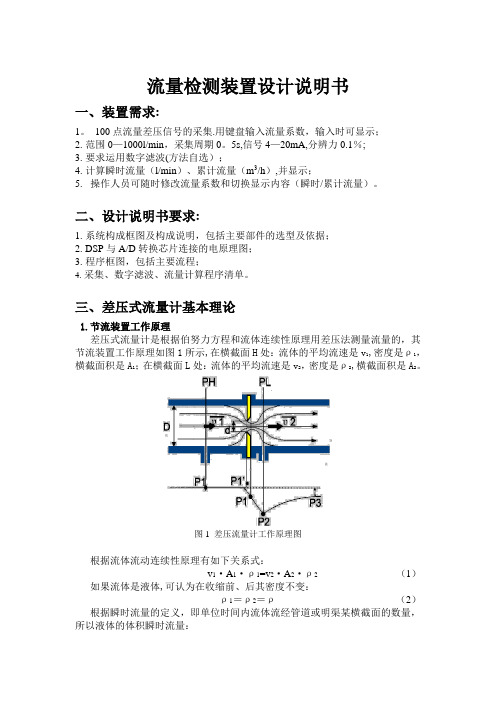
三、差压式流量计基本理论1.节流装置工作原理差压式流量计是根据伯努力方程和流体连续性原理用差压法测量流量的,其节流装置工作原理如图1所示,在横截面H处:流体的平均流速是v1,密度是ρ1,横截面积是A1;在横截面L处:流体的平均流速是v2,密度是ρ2,横截面积是A2。
图1 差压流量计工作原理图根据流体流动连续性原理有如下关系式:v1·A1·ρ1=v2·A2·ρ2 (1)如果流体是液体,可认为在收缩前、后其密度不变:ρ1=ρ2=ρ(2)根据瞬时流量的定义,即单位时间内流体流经管道或明渠某横截面的数量,所以液体的体积瞬时流量:2211A v A v q v ⋅=⋅= (3)根据伯努利方程(能量守恒定律),在水平管道上Z1=Z2,则有如下关系式:2222222111v P v P ρρ+=+ (4)应用伯努利方程和流动连续性原理,在两个横截面上压力差则有如下关系式:)(2212221v v P P P -=-=∆ρ (5)将(3)代入(5)式,并整理,则得:22212])(1[2v A A P -=∆ρ(6)由于421D A ⋅=π, 422d A ⋅=π, 定义直径比Dd =β, 其中d 为工作状况下节流件的等效开孔直径,D 为管道直径,则得到:2224)1(2A q P v βρ-=∆ (7) 这样可推导出以下的理论流量公式:1242411ρπβPd q v ∆⋅-= (8)又由于流量系数C 的定义是:C= 实际流量/理论流量,可得出节流式差压流量计普遍适用的测量体积流量的实际流量公式:ρπβεPd C q v ∆⋅-⋅=24124 (9)其中,ε为被测介质的可膨胀性系数:对于液体=1; 对气体、蒸气等可压缩流体<1 。
- 1、下载文档前请自行甄别文档内容的完整性,平台不提供额外的编辑、内容补充、找答案等附加服务。
- 2、"仅部分预览"的文档,不可在线预览部分如存在完整性等问题,可反馈申请退款(可完整预览的文档不适用该条件!)。
- 3、如文档侵犯您的权益,请联系客服反馈,我们会尽快为您处理(人工客服工作时间:9:00-18:30)。
《传感器技术及应用》课程设计说明书课设题目流量检测系统班级姓名学号指导教师时间摘要流量是三大工业过程控制量之一,流量计量直接关系到国家利益和国计民生。
电磁流量计因测量时不受被测介质的温度、粘度、密度等影响,应用领域非常广泛。
因此,设计一个流量检测系统。
设计的流量检测系统以AT89C51单片机为核心,管道流量的检查采用电磁流量计,电磁流量计输入4~20mA的电流信号,通过I/A转为0~5V的电压信号,经AD转换送与单片机转换为流量数据,在液晶屏幕LCD1602中显示。
该流量检测系统可检测小口径管道流量,因不受流体材料的限制,常应用于食品工业。
关键词:电磁流量计,AT89C51单片机目录一、绪论1.1课题开发的背景和现状1.2课题开发的目的和意义1.3课题技术性能指标二、流量计种类选择方案三、系统总体方案设计四、主要器件的方案选择4.1、HR-LDG系列电磁流量传感器4.2、单片机的方案选择五、模块电路的设计5.1、MCU主控电路5.2、LCD1602液晶显示电路5.3、电流/电压转换电路5.4、A/D转换电路5.5、电源模块六、电磁流量计安装时注意事项七、系统软件开发流程及代码分析八、设计总结九、参考文献附录1、总电路图2、元器件清单一、绪论1.1课题开发的背景和现状工业生产中过程控制是流量测量和仪表应用的一大领域,流量与温度、压力和物位一起称为过程控制中的四大参数,人们通过这些参数对生产过程进行监视与控制。
对流体流量进行正确测量和调节是保证生产过程安全经济运行、提高产品质量、降低物质消耗、提高经济效益、实现科学管理的基础。
流量的检测与控制在化工、能源电力、冶金、石油等领域应用广泛。
例如:在天然气工业蓬勃发展的现在,天然气的计量收起了人们的特别关注,因为在天然气的采集、处理储存、运输和分配过程中,需要数以百万计的流量计,其中流量蠩涉及到的结算金额数字巨大,对测量和控制准确度和可靠性要求特别训。
此外,在环境保护领域,流量测量仪表也分演着重要角色。
人们为了控制大气的污染,必须对污染大气的烟气以及其分温室气体排放进行监测;废液和污水的排放,使地表水源和地下水源受到污染,人们必须对废液和污水进行处理,对排放量进行控制。
于是数以百万计的烟气排放点和污水排放口都成了流量测理对象。
同时在科学试验领域,需要大量的流量控制系统进行仿真与试验,流量计在现代家业、水利建设、生物工程、管道输送、航天航空、军事领域等也有广泛的应用。
1.2课题开发的目的和意义在现代工业生产过程自动化中,流量是重要的过程参数之一。
流量是衡量设备的效率和经济性的重要指标;流量是生产操作和控制的依据,因为在大多数工业生产中,常用测量和控制流量来确定物料的配比与耗量,实现生产过程自动化和最优控制。
同时为了进行经济核算,也必须知道如一个班组流过的介质总量。
所以,流量的测量与控制是实现工业生产过程自动化的一项重要任务。
例如:由于石油是重要的能源,无论上从节约能源的角度,还是从经济性角度来看,对于流量的精确控制都是十分必要的,所产生的经济效益也是十分明显的。
在自来水的监测与流量控制中,应用高精度的流量计量与控制仪表也是必须的,所带来的经济效益是十分巨大且显而易见的。
开展石油化工过程流程模拟、先进控制与过程优化技术的研究与应用具有十分重要的现实意义,是当前国内外石油化工界广泛关注的一个话题。
自动化技术可以提高计量准确度、数据可靠性和及时性,为优化生产运行、核算经济效益、强化生产调度和有效监控生产过程,进一步降低泵站工业噪声污染,改善职工工作条件,减轻劳动强度,避免职业伤害,延长设备使用寿命以及企业节能降耗工作起到积极作用。
1.3课题技术性能指标(1)小口径的电磁流量计,应用于食品工业;(2)检测管道的流量;(3)所测流量送液晶显示。
二、流量计种类选择方案目前,常用的流量计有:涡轮流量计、电磁流量计和明渠流量计3种。
因此,初步有三种方案设计可选用。
1、方案一采用明渠流量计进行流量的检测。
HOH-L-01多普勒明渠流量计测量系统的组成方法一般由一台流量显示仪、一台流速计、一台液位计组成;也可由一台流量显示仪、多台流速计、一台液位计组成的多点流速测量的明渠流量系统。
HOH-L-01多普勒明渠流量计系统,适用于水库、河流、水利工程、城市供水、污水处理、农田灌溉、水政水资源等矩形、梯形明渠及涵洞的流量测量,此次设计中应用于食品工业,故不适合使用明渠流量计。
2、方案二采用涡轮流量计进行流量检测。
涡轮流量计由涡轮、轴承、前置放大器、显示仪表组成。
被测流体冲击涡轮叶片,使涡轮旋转,涡轮的转速随流量的变化而变化,即流量大,涡轮的转速也大,再经磁电转换装置把涡轮的转速转换为相应频率的电脉冲,经前置放大器放大后,送入显示仪表进行计数和显示,根据单位时间内的脉冲数和累计脉冲数即可求出瞬时流量和累积流量。
涡轮流量计在一些对于准确度要求不高的场合得到了广泛的应用,但其不能长期保持校准特性,流体对流量特性有较大影响,对于食品安全流量检测,不适合于用此涡轮流量计。
3、方案三采用电磁流量计进行流量检测。
电磁流量计的测量管是一个内衬绝綠材料非导磁合金短管。
两只电极沿径方向透壁固定在测量管上,其电极头与衬头内表面基本齐平。
励磁线圈由双向方波脉冲劢磁时,将在与测量管轴线垂直的方向上产生一磁通量密度为B的工作磁场,此时,如果具有一定电导率的液体流经测量管,将切割磁力线感应出电动势E。
电动势E正比于磁通量密度B、测量管内径d与平均流速V的乘积。
电动势E(流量信号)由电极检出并通过电缆送至转换器。
转换器将流量信号放大处理后,可显示流体流量,并能输出脉冲,模拟电流等信号,用于流量的控制与调节。
电流量计有如下特点:(1)属于非接触性仪表,测量管段是光滑直管,管内没有任何阻碍流体流动的节流元件,不会引起额外的压力损失,节能效果好,可用于测量各种粘度的液体,特别适于测量含固体颗粒的液固混合流。
此外除电极外没有其他组件与液体直接接触,因此它还适于测量腐蚀性大的液体,由此形成了独特的应用领域。
(2)流量计测量过程不受被测介质的温度、粘度、密度等因素的影响,因此只需一次经水标定后就可用于测量其他导电液体的流量。
(3)电磁场的产生是极快的过程,因此电磁流量计反应速度快,无机械惯性,可以测量瞬时流量,还可测水平或垂直管道中两个轴向的流量。
(4)流量计输出只与被测介质的流速有关,量程范围宽。
(5)应用口径范围大,小口径、微小口径常用于医药卫生等有卫生要求的场所,中小口径常用于高要求或难测场合,如造纸工业测量纸浆液,大口径多用于给排水工程。
对比以上三种方案,方案一中适合应用于水库、河流、水利工程、城市供水、污水处理、农田灌溉、水政水资源等矩形、梯形明渠及涵洞的流量测量,此次设计中应用于食品工业,管道内流量的流速测量,故不适合使用明渠流量计。
方案二中涡轮流量计主要应用于石油、有机液体、无机液,液化气,天然气和低温流体,不适合选用涡轮流量计。
方案三中流量计测量过程不受被测介质的温度、粘度、密度等因素的影响,因此只需一次经水标定后就可用于测量其他导电液体的流量,可用于食品工业流速的检测,因此对比前两种方案可得此次设计中采用电磁流量计进行流速的检测。
三、系统总体方案设计工作原理:基于电磁流量计的管道流量检测系统实现的功能为检测管道的流量,送液晶显示。
管道流量的检查采用电磁流量计,电磁流量计输入4~20mA 的电流信号,通过I/A转为0~5V的电压信号,经AD转换送与单片机转换为流量数据,在液晶屏幕LCD1602中显示。
系统框图见图:系统框图四、主要器件的方案选择4.1、HR-LDG系列电磁流量传感器一般工业用电磁流量计被测介质流速为2~4m/s为宜,在特殊情况下,最低流速应不小于0.1m/s,最高不大于8m/s。
若介质中含有固体颗粒,常用流速应小于3m/s,以防止衬里和电极的过分摩擦:对于粘滞流体,流速可选择大于2m/s,较大的流速有助于自动消除电极上附着的粘滞物的作用,有利于提高测量精度。
在流量Q已确定的条件下,即可根据上述流速V的范围决定流量计口径D的大小,其值计算公式为:Q=πD2V/4式中,Q:流量(m3/h);D:管道内径(m);V:流速(m/h)。
(1)电磁流量计的工作原理与组成电磁流量计的测量管是一个内衬绝綠材料非导磁合金短管。
两只电极沿径方向透壁固定在测量管上,其电极头与衬头内表面基本齐平。
励磁线圈由双向方波脉冲劢磁时,将在与测量管轴线垂直的方向上产生一磁通量密度为B的工作磁场,此时,如果具有一定电导率的液体流经测量管,将切割磁力线感应出电动势E。
电动势E正比于磁通量密度B、测量管内径d与平均流速V的乘积。
电动势E(流量信号)由电极检出并通过电缆送至转换器。
转换器将流量信号放大处理后,可显示流体流量,并能输出脉冲,模拟电流等信号,用于流量的控制与调节。
导电性液体在垂直磁场的非磁性测量管内流动,与流动方向垂直的方向上产生与流量成比例的感应电势,电动势的方向按“弗来明右手规则”,其计算公式为E=kBD V(式1)式中,E:感应电动势,即流量信号,V;K:系数;B磁感应强度,T;D:测量管内径,m;V:平均流速,m/s.设液体的体积流量为qv (m3/s), qv=πD2V/4 (式2)则E=(4kB/πD)qv =kqv(式3)式中K为仪表常数,K=4kB/πD。
式1中K、d为常数,由于励磁电流是恒流的,因此B也是常数。
由E=kBD V可知,体积流量Q与信号电压E成正比,即流速感应的信号灯电压E与体积流量Q成线性关系。
因此,只要测量出E就可以确定流量Q,这就是电磁流量计的基本工作原理。
由E=kBD V可知,被测流体介质的温度、密度、压力、电导率、液固两相流体介质的液固成公比等参数不会影响测量结果。
至于流动状态,只要符合轴对称流动就不会影响测量结果。
因此,电磁流量计是一种真正的流量计。
对于制造厂和用用户来说,只要用普通的的水实际标定后就可测量其他任何导电流体的体积,而不需要任何修正,这是电磁流量计的一突出特点,也是其他任何流量计所没有的。
测量管内无活动及阻流部件,因此几乎没有压力损失,并具有很高的可靠性。
EMF由流量传感器和转换器两大部分组成。
传感器的测量管上下装有激磁线圈,能激磁电流后产生磁场穿过测量管,一对电极装在测量管内壁与液体相接触,引出感应电势,送到转换器。
激磁电流则由转换器提供。
(2)电磁流量传感器的选择电磁流量计的量程Q应大于预计的最大流量值,而正常的流量值以稍大于流量计满量程高刻度的50%为宜。
口径大小与流量范围对应如下表所示。
表2 口径大小与流量范围对应参考表在本系统中选用HR-LDG-D25-T0-F1-C0-E1-H0-G1-D型电磁流量计,流量范围为0.4~14 m3/h,介质温度为0℃-80℃,衬里材料为耐磨橡胶,电极材料为216L,工作压力为2.5Mpa,全系列口径,连接方式为法兰式,转换器结构为一体式智能表头,220VAC供电电压,输出为4-20mA,防爆类型为隔爆型。