外文翻译:探讨汽车轮胎滚动阻力以及测试技术
毕业设计翻译
山东理工大学毕业设计(论文)外文翻译资料英文题目:Experimental verification and finite element modeling of radial truck tireunder static loading翻译题目:车辆轮胎径向固有频率和阻尼系数的研究学院:交通与车辆工程学院专业:车辆工程学生姓名:王臣指导教师:刘瑞军车辆轮胎径向固有频率和阻尼系数的研究摘要--车辆轮胎径向固有频率和阻尼比的测量方法已经有所研究。
从小客车轮胎到货车巴士轮胎的径向固有频率和阻尼比都已经被报道。
轮胎的径向模态参数承受不同水平的充气压力,已通过使用频率响应函数的方法来确定。
为了获得理论上的固有频率和振型,轮胎的平面振动已被建模为貌似一个圆形光束的模型。
使用Tielking方法是基于Hamilton原理,理论结果证实旋转速度,切向和径向刚度,径向速度和拉力是由于轮胎的充气压力造成的。
结果表明,实验条件下可以认为是参数改变了固有频率和阻尼比。
关键词-阻尼比、频率响应函数法、充气压力、模态振型、径向固有频率、子午线轮胎1. 引言在当今世界,通过减少汽车的震动,提高驾驶的质量具有重要意义。
通常情况下,很多汽车的振动来源于刚发动的时候,振动速率的影响逐渐增加。
特别是,轮胎不仅作为初始旋转接触路面,从路面影响传送到汽车的主体进入汽车的内部,而且,在于轮胎已经对增强乘坐的质量有很大的影响。
回顾在轮胎振动上已建立的研究,Tielking研究飞机充气轮胎的振动特性,假定轮胎的运动是圆形壳的运动。
有Tielking理论的基本原则,Bohm通过研究轮胎运动和静止的特征同时假设轮胎是弹性环,提出了轮胎的运动方程。
Bohm用实验的方法来验证了他的方程。
Barons也研究了振动对旋转轮胎的影响。
Potts等人建模的轮胎为薄环,并考虑到质量和几何形状研究了轮胎的固有频率。
Soedel 和Prasad等人用分析方法研究了轮胎在路表面载荷下的振动特性,例如,解释在自由状态下的振动特性。
轮胎滚动阻力影响因素及测试方法
轮胎滚动阻力影响因素及测试方法
何燕;张忠富
【期刊名称】《轮胎工业》
【年(卷),期】2004(024)004
【摘要】分析影响轮胎滚动阻力的因素并介绍滚动阻力测试方法.在胎面胶中合理使用BR、S-SBR、白炭黑和高芳烃油,骨架材料使用芳纶帘线,均可降低轮胎滚动阻力.此外,轮胎的子午化、扁平化和无内胎化的结构变化也可有效降低滚动阻力.滚动阻力测试方法主要有测力法、测扭矩法、测功率法和测减速度法.
【总页数】4页(P238-241)
【作者】何燕;张忠富
【作者单位】华中科技大学,能源与动力工程学院,湖北,武汉,430074;青岛石油化工厂,山东,青岛,266042
【正文语种】中文
【中图分类】TQ336.1;TQ330.7+3
【相关文献】
1.轮胎滚动阻力影响因素及测试方法研究 [J], 韩福涛;苏杰;刘晓民;邢力;毛成涛;黄蒲;史松杰;满忠雷;张少岩
2.轮胎滚动阻力影响因素及测试方法研究 [J], 韩福涛;苏杰;刘晓民;邢力;毛成涛;黄蒲;史松杰;满忠雷;张少岩;
3.轮胎滚动阻力测试方法研究 [J], 陈绪飞;徐艳林
4.轮胎滚动阻力测试方法分析 [J], 谢海粟
5.轮胎滚动阻力测试方法分析 [J], 谢海粟
因版权原因,仅展示原文概要,查看原文内容请购买。
国内外轮胎滚动阻力试验方法及影响因素分析

国内外轮胎滚动阻力试验方法及影响因素分析一、引言轮胎的滚动阻力是指轮胎在运动过程中与地面之间相互摩擦产生的阻力。
滚动阻力不仅直接影响车辆的燃油经济性能,还与车辆的操控性、行驶稳定性等密切相关。
因此,研究轮胎滚动阻力试验方法以及影响因素的分析具有重要的理论和实际意义。
二、试验方法1.滚动阻力试验仪滚动阻力试验通常使用滚动阻力试验仪进行。
该试验仪由电机、加载装置、计算机数据采集系统等组成,能够模拟车辆在实际行驶过程中轮胎与地面之间的相互作用。
2.试验条件滚动阻力试验需要控制一些试验条件,如载荷、速度、温度、湿度等。
载荷是指施加在轮胎上的作用力,通常以静态载荷或动态载荷形式存在。
速度是指轮胎在试验过程中运动的速度,不同的速度下滚动阻力也会有所变化。
温度和湿度的变化可能对轮胎材料的性能产生影响,因此也需要在试验过程中进行相应的控制。
3.试验过程滚动阻力试验的过程一般包括以下几个步骤:将轮胎安装在试验机上,设定好试验条件,启动试验仪进行测试,采集测试数据并进行分析与处理。
1.轮胎结构轮胎的结构对滚动阻力具有重要影响。
胎面花纹、胎壁硬度以及胎体材料等因素均会影响轮胎与地面之间的摩擦情况,从而影响滚动阻力的大小。
2.载荷大小载荷大小是影响轮胎滚动阻力的重要因素之一、较大的载荷会使轮胎与地面之间的接触面积增大,从而增加了摩擦力,导致滚动阻力增加。
3.车辆速度车辆速度也是影响轮胎滚动阻力的重要因素。
较高的速度使轮胎在与地面接触时所受到的压力变大,从而增加了滚动阻力。
4.轮胎温度和湿度轮胎的温度和湿度的变化也会对滚动阻力产生一定的影响。
一般来说,较高的温度和湿度会导致轮胎材料的硬度降低,从而增加了滚动阻力。
5.地面条件地面的情况也会对轮胎滚动阻力产生影响。
不同类型的地面摩擦系数不同,因此会导致轮胎滚动阻力的变化。
综上所述,轮胎滚动阻力试验方法的选择以及影响因素的分析对于优化轮胎设计、提高车辆燃油经济性能具有重要意义。
中英文文献翻译-汽车车轮侧滑量检测存在问题及对策研究
附录B 外文文献Problems in Measurement of Automotive Wheel Side Slip and Corresponding Counter MeasureOn the basis of analyzing the generation mechanism of side slip,problems in measurement of side slip,such as great degree of separation,judgment out of truth,etc.,are discussed.It is pointed out that,besides velocity,load,tire pressure,etc.,technical state of side slip testing bench,design of measurement station are also reasons for these problems.In order to resolve these problems,effective measures for ensuring accuracy of measuring results and correct judgment,such as keeping stable measurement condition,developing reasonable standards and application of advanced measurement technology,etc.,are presented.Through the test of the verification of lateral spreads, often finds the over-error of indication, the reason caused there are basically two aspects: one is the mechanical reasons, mainly is sliding board, linkage institutions and back to zero institutions, clearance by increasing wear parts, 2 it is the cause of the electrical testing instruments, or within the sensor electronic devices, zero drift, aging resistance changes caused by damage or element. Adjust the method is as follows:Machinery examinationuse spring tension plan, check the pull and back to zero.The size of the tension and back to the stand or fall of zero depends on two aspects, one is the lubrication system is good or bad, 2 it is back to zero spring aid. The reason for the first on the one hand, the measures should be taken under the skateboard is: check the roller and guide them and clean or replace, check the two pieces of board of middle guide bearing and other bearing and to clean or replace. For the second reasons, the measures should be taken to ensure that is: in zero error is not exceeds the premise cut loose "back to zero spring". Due to the reason of tension on the structure, the size and back to the stand or fall of zero is a pair of contradictory, and the tight "back to zero spring" is back to zero, but pulling force change, the pine "back to zero spring" is pulling force small, but back to zero is not good. So in the adjustment of the "back to zero spring" must give consideration to the tension and back to zero 2 a index.check and adjustment of the synchronicityTo use two pieces of BaiFenBiao inspection. Each of the installation board a BaiFenBiao, zero initiative after the completion of the push board (with sensors on one side of the), check the value of two pieces of BaiFenBiao, can read the stand or fall of synchronicity. In the only a piece of BaiFenBiao, will BaiFenBiao into the driven plate, and direct contact with the initiative of the sensor board displacement can be through the measurement instrument to display. The causes of error synchronicity has the following two aspects, on the one hand, the skateboard steering mechanism of bearings between the cause, followed by linkage institutions synchronous lever uniform creates. The form is not identical also, bearing clearance cause of synchronization is generally two pieces of skateboarding is a constant, the length of the board has nothing to do with promoting, and linkage institutions synchronous lever errors is a variable, the error will move along with the skateboard increased. If the driven plate, the value of the larger, driven plate that leverage far away from central shaft, if driven plate, the smaller the driven plate that values from the center axis is close to leverage, adjust any a board, just pay attention to the direction of the adjustment.附录C外文文献的中文译文汽车车轮侧滑量检测存在问题及对策研究通过对侧滑试验台的检定,往往会发现示值超差,造成的原因基本上有两个方面:一是机械方面的原因,主要是滑动板、联动机构及回零机构机件磨损,间隙增大所致,二是电气方面的原因,测试仪表或传感器内的电子器件老化、零点漂移、阻值变化或元件损坏所致。
轮胎压力监测中英文对照外文翻译文献
中英文资料外文翻译文献参考文献Monitoring the Tire Pressure at Cars Using Passive SAW SensorsAbstract:In our paper we present the application of surface acoustic wave (SAW) sensors to the continuous manitaring of the tire pressure in road ve hicles. With these, the tire pressure can be read out in every phase of driving. We show the implemented prototype setup for measurement of the tire pressu re, the applied SAW sensors, improved versions and the interrogation setup. The problems in practical application are discussed. Experimental result s measuring the tire pressure during test rides are presented.INTRODUCTIONOperating a road vehicle, a malfunction of the tires in motion due to a tire puncture can cause serious accidents and endanger human life. Furthermore, nowadays manufacturers of cars try to save the spare wheel in vehicles. Usually it only costs weight and space, therefore it yields a higher fuel consumption,although it will be required less than one time in more than ten years of a car's life. This only can be done, if the air pressure in the tires can be measured even during driving. Currently used sensors contain active components, powered by a Lithium battery. The mass of these sensor assemblies is about 20 grams causing high dynamic load. A few years ago,wirelessIy interrogable SAW devices far sensor applications were invented. [1,2, 3]. Using an one port SAW delay line connected to an antenna only, an RF interrogation signal is fed into and the sensor response,carrying thesensor information is retransmitted wirelessly to the interrogator. These sensors are capable for measurement of temperature, mechanical load, force and displacement, etc. The advantage is, that SAW sensors are totally passive devices and contain neither power supply nor semiconductors. They withstand temperatures up to several hundreds of degree centigrades, their lifetime is much longer than that of battery powered systems.Further,in vehicles strong electromagnetic pollution is generated by ignition systems etc.SAW sensors operate without risk of damage even in rough environments. First we discuss pressure measurement employing SAW sensors with wireless interrogation.We present some types of sensor assemblies and the interrogation system.Next we discuss the implementation into thecar and thenwepresent experimentally results.Finally a brief summary concludes the content of the paper.SAW PRESSURE SENSORSThe electrical behaviour of a passive SAW pressure sensor always is that of a one port delay line with multiple reflectors or a resonator,respectively. In the delay linecase,the interrogator transmits a burst signal,the sensor responds with a chain of bursts,one for every reflector arranged at the substrate's surface.The differential delay between two or more response signals is evaluated.To measure some physical value,the parameter has to be converted into a change of sensor's surface length or surface acoustic wave's velocity,respectively.The delay ri of the response of areflector i is the ratio of SAW propagation length Li on the substrate's surface and propagation velocityv,.Affecting the sensor with a measurand causes a scaling of the sensor's response to be observed as individual delay shifts Ari of the response signals si originating frotmhe reflectors i.Mechanical measurands can be collected by loading the sensor mechanically.Apart from stretching and compressing,utilized for wireless measurement of torque,etc.the SAW sensor's substrate can be bent.Pressure can affect the sensor by bending a membrane,shifting the edge of a sensor fixed on theother side.Here the sensor is loaded to be bent due to a shift of the center of a membrane loaded by the pressure.On the other hand the sensor can directly be fitted to the membrane or a piezoelectric membrane representing the SAW substrate can be used.Figure 1 shows these methods.Fig.1:a)Membrane converting pressureto shift bendingthe SAW sensor(SAWS)b)SAW sensor fitted to the membraneThe next step is to cover the sensor membrane by a cap consisting of a spacer frame and a quartz cover plate.This yieldsanintegratedpressure chamber SAW sensor[4](fig.2).Fig.2:Integrated pressure chamber SAW sensorThecover protects theSAW generating metallic structure from oxidation and thesurface from dust.The cavity can befiIledwith a gas at reference pressure.If the cavity is evacuated,absolute pressure values can bemeasured.Measurement is made byinterrogationusing simple RF burst signals.The response impulses are evaluated in magnitude and phase.Bending the membrane due to pressure loadyields a phase shift of for instance 100 degree for lo4 Pascal.With this theairpressure in car tires can be measuredwith a resolutioonf approx.IO'Pascal(0.01 Bar).To reduce the amount of data to process,for the implementation in cars the resolution was reduced to 50 mBar.IMPLEMENTATIONThe first prototype used for the experimental measuremenwtsas a pressure chamber with a membrane made of brass.The sensor unit was fitted to a hub cap andwas connected to the valve by a pressure assembly(fig.3).Fig.3:First prototype of pressure chamber formeasurement of tire pressureFor serial manufacture the sensor system~have tobe much smaller and able to be integrated in the tire.Therefore we implemented the integrated pressure chamber(fig.2)into the tire.The sensor was fixed to the rim,the metallic valve shaft was used as the sensor's antenna(fig.4).Fig.4:Integrated pressure chamber fixed to the rim,valve used as antennaFoirmproved implementation a sensor assembly only fitted to the valve was developed(fig.5).The total mass of the unit is only a few grams,the dynamic load is small even driving at high speed.Fig.5:Pressure sensor forfitting into the valve shaftThcear based interrogation system uses space diversity to distinguish the sensors in the tires.Therefore below every car wing an antenna has to be employed.We used coaxial cables,hut it is difficult and expensive to use them in cars.Our investigationsshow the applicability of twisted pair wires too.Fig.6:Interrogation antenna on carFor measurement we developed a small sized interrogation system transmitting bursts and looking for the phase shift between the response signal bursts.The system was controlled by a one chip microcontroller and abisle to display the measurement result on aLCD display.In fig.7 a photograph of the system is shown.Fig.7:System for wireless interrogation of passiveSAW sensors(50 x 100 x 160 mm’)MEASUREMENTRESULTSTo test our sensors and our system we made a lot of test rides within the area and around the city of Vienna.The interrogation system was coupled to alaptop computer.The pressure values were measured and recorded to a file. Thefigures 8 and 9 show characteristic behaviour of tire pressure for different driving conditions. Due to the shocks from a rugged lane,in the left part of fig.8 the absolute pressure value swings around the mean value by the least significant bit,0.05 Bar.The narrow higher peaks of tire pressure belong to braking maneuvers(the sensor was mounted toa front wheel).The longer increase of tire pressure and the following period of decay is due to riding over a curbstone.The system showed high reliability even when driving in a heavy snow storm. tire pressure[Bar]Fig.8:Tire pressure for different driving conditionsIn figure 9 the pressure in the right front wheel can be observed zoomed in time while passing a two track grade crossing with an adjacent water channel across the lane.Due to the dilapidated arrangement of the grade crossing,hard shocks are transmitted to thecar body causing hard pressure shocks in the tires.Fig.9:Tire pressure crossing a grade crossing withtwo tracks and a water channel across the laneDISCUSSIONSAW sensors with wirelessly interrogation are free of maintenance and withstand high thermal and mechanical load.The measurement performance is comparable to that of competitors.The effort in car based system is higher for SAW sensors,since theactive sensor units transmit preconditioned digital information containing pressure valueand sensor The major advantage of SAW devices in identification. applications,where high revolutions per time occur, is their low mass.The centrifugal force is m.v*/r,with the mass m,the velocity v and the radius r.To minimize dynamic mechanical load,the mass of a system applied to rotating parts should be as low as possible.Whereas conventional sensor units for tire pressure measurements have a mass of approx.20 grams,the integrated pressure sensor itself(fig.5) has a mass of less than one gram.The complete SAW sensor unit's mass in worst case is only a few grams.Conventional systems are powered by a Lithium battery.In case of a worntire,since the battery cannot be checked,the sensor should be replaced too,yielding problems of waste disposal.For a system integrated in the car electronic,it is needless to display the pressure of each tire continuously.Here,only a malfunction should trigger an alert.The system's display can be canceled,reducing system's cost.CONCLUSIONTheadvantagews of passive SAW sensors make thwemell suited for vehicular applications.Especially for measurement of tire pressure low mass and the fact thatthey are free of maintenance makethem to be superior over the competitors.The SAW sensors for pressure measurement,the implementation in tires and the system for interrogation were discussed.Experimental results out of a lot of measurement rides were presented.REFERENCES[l]Reindl,F.Muller,C.Ruppel,WE.Bulst and F.Seifert,Passive surface wave sensors which can be.wirelessly interrogated,International Patent Appl WO 93/13495(1992).[2]Seifert F.,Bulst W.E.,Ruppel C.,Mechanical sensors based on surface acoustic waves,Sensors andActuators,A44(1994)231-239[3]G.Scholl,T.Ostertag,L.Reindl,H.Scherr,0.Sczesny,U.Wolff,Wireless SAW Sensors for Remote Measurement of Physical Parameters,Proc.IEEE Intern.Workshopon Commercial Radio Sensors and Communication Techniques,1997,pp.51-58.[4]H.Scherr,G.Scholl,F.Seifert,R.Weigel,Quartz Pressure Sensor Based on SAW Reflective Delay Line,Proc.IEEE Ultrasonics Symposium 1996,pp.347-350.译文轮胎压力监测在汽车使用被动声表面波传感器摘要:在我们的文件,我们目前的应用表面声波(声表面波)传感器不断的轮胎压力在道路车辆。
汽车轮胎压力监测中英文对照外文翻译文献
中英文资料翻译参考文献Monitoring the Tire Pressure at Cars Using Passive SAW SensorsAbstract:In our paper we present the application of surface acoustic wave (SAW) sensors to the continuous manitaring of the tire pressure in road ve hicles. With these, the tire pressure can be read out in every phase of driving. We show the implemented prototype setup for measurement of the tire pressu re, the applied SAW sensors, improved versions and the interrogation setup. The problems in practical application are discussed. Experimental result s measuring the tire pressure during test rides are presented.INTRODUCTIONOperating a road vehicle, a malfunction of the tires in motion due to a tire puncture can cause serious accidents and endanger human life. Furthermore, nowadays manufacturers of cars try to save the spare wheel in vehicles. Usually it only costs weight and space, therefore it yields a higher fuel consumption,although it will be required less than one time in more than ten years of a car's life. This only can be done, if the air pressure in the tires can be measured even during driving. Currently used sensors contain active components, powered by a Lithium battery. The mass of these sensor assemblies is about 20 grams causing high dynamic load. A few years ago,wirelessIy interrogable SAW devices far sensor applications were invented. [1,2, 3]. Using an one port SAW delay line connected to an antenna only, an RF interrogation signal is fed into and the sensor response,carrying thesensor information is retransmitted wirelessly to the interrogator. These sensors are capable for measurement of temperature, mechanical load, force and displacement, etc. The advantage is, that SAW sensors are totally passive devices and contain neither power supply nor semiconductors. They withstand temperatures up to several hundreds of degree centigrades, their lifetime is much longer than that of battery powered systems.Further,in vehicles strong electromagnetic pollution is generated by ignition systems etc.SAW sensors operate without risk of damage even in rough environments. First we discuss pressure measurement employing SAW sensors with wireless interrogation.We present some types of sensor assemblies and the interrogation system.Next we discuss the implementation into thecar and thenwepresent experimentally results.Finally a brief summary concludes the content of the paper.SAW PRESSURE SENSORSThe electrical behaviour of a passive SAW pressure sensor always is that of a one port delay line with multiple reflectors or a resonator,respectively. In the delay linecase,the interrogator transmits a burst signal,the sensor responds with a chain of bursts,one for every reflector arranged at the substrate's surface.The differential delay between two or more response signals is evaluated.To measure some physical value,the parameter has to be converted into a change of sensor's surface length or surface acoustic wave's velocity,respectively.The delay ri of the response of areflector i is the ratio of SAW propagation length Li on the substrate's surface and propagation velocityv,.Affecting the sensor with a measurand causes a scaling of the sensor's response to be observed as individual delay shifts Ari of the response signals si originating frotmhe reflectors i.Mechanical measurands can be collected by loading the sensor mechanically.Apart from stretching and compressing,utilized for wireless measurement of torque,etc.the SAW sensor's substrate can be bent.Pressure can affect the sensor by bending a membrane,shifting the edge of a sensor fixed on theother side.Here the sensor is loaded to be bent due to a shift of the center of a membrane loaded by the pressure.On the other hand the sensor can directly be fitted to the membrane or a piezoelectric membrane representing the SAW substrate can be used.Figure 1 shows these methods.Fig.1:a)Membrane converting pressureto shift bendingthe SAW sensor(SAWS)b)SAW sensor fitted to the membraneThe next step is to cover the sensor membrane by a cap consisting of a spacer frame and a quartz cover plate.This yieldsanintegratedpressure chamber SAW sensor[4](fig.2).Fig.2:Integrated pressure chamber SAW sensorThecover protects theSAW generating metallic structure from oxidation and thesurface from dust.The cavity can befiIledwith a gas at reference pressure.If the cavity is evacuated,absolute pressure values can bemeasured.Measurement is made byinterrogationusing simple RF burst signals.The response impulses are evaluated in magnitude and phase.Bending the membrane due to pressure loadyields a phase shift of for instance 100 degree for lo4 Pascal.With this theairpressure in car tires can be measuredwith a resolutioonf approx.IO'Pascal(0.01 Bar).To reduce the amount of data to process,for the implementation in cars the resolution was reduced to 50 mBar.IMPLEMENTATIONThe first prototype used for the experimental measuremenwtsas a pressure chamber with a membrane made of brass.The sensor unit was fitted to a hub cap andwas connected to the valve by a pressure assembly(fig.3).Fig.3:First prototype of pressure chamber formeasurement of tire pressureFor serial manufacture the sensor system~have tobe much smaller and able to be integrated in the tire.Therefore we implemented the integrated pressure chamber(fig.2)into the tire.The sensor was fixed to the rim,the metallic valve shaft was used as the sensor's antenna(fig.4).Fig.4:Integrated pressure chamber fixed to the rim,valve used as antennaFoirmproved implementation a sensor assembly only fitted to the valve was developed(fig.5).The total mass of the unit is only a few grams,the dynamic load is small even driving at high speed.Fig.5:Pressure sensor forfitting into the valve shaftThcear based interrogation system uses space diversity to distinguish the sensors in the tires.Therefore below every car wing an antenna has to be employed.We used coaxial cables,hut it is difficult and expensive to use them in cars.Our investigationsshow the applicability of twisted pair wires too.Fig.6:Interrogation antenna on carFor measurement we developed a small sized interrogation system transmitting bursts and looking for the phase shift between the response signal bursts.The system was controlled by a one chip microcontroller and abisle to display the measurement result on aLCD display.In fig.7 a photograph of the system is shown.Fig.7:System for wireless interrogation of passiveSAW sensors(50 x 100 x 160 mm’)MEASUREMENTRESULTSTo test our sensors and our system we made a lot of test rides within the area and around the city of Vienna.The interrogation system was coupled to alaptop computer.The pressure values were measured and recorded to a file. Thefigures 8 and 9 show characteristic behaviour of tire pressure for different driving conditions. Due to the shocks from a rugged lane,in the left part of fig.8 the absolute pressure value swings around the mean value by the least significant bit,0.05 Bar.The narrow higher peaks of tire pressure belong to braking maneuvers(the sensor was mounted toa front wheel).The longer increase of tire pressure and the following period of decay is due to riding over a curbstone.The system showed high reliability even when driving in a heavy snow storm. tire pressure[Bar]Fig.8:Tire pressure for different driving conditionsIn figure 9 the pressure in the right front wheel can be observed zoomed in time while passing a two track grade crossing with an adjacent water channel across the lane.Due to the dilapidated arrangement of the grade crossing,hard shocks are transmitted to thecar body causing hard pressure shocks in the tires.Fig.9:Tire pressure crossing a grade crossing withtwo tracks and a water channel across the laneDISCUSSIONSAW sensors with wirelessly interrogation are free of maintenance and withstand high thermal and mechanical load.The measurement performance is comparable to that of competitors.The effort in car based system is higher for SAW sensors,since theactive sensor units transmit preconditioned digital information containing pressure valueand sensor The major advantage of SAW devices in identification. applications,where high revolutions per time occur, is their low mass.The centrifugal force is m.v*/r,with the mass m,the velocity v and the radius r.To minimize dynamic mechanical load,the mass of a system applied to rotating parts should be as low as possible.Whereas conventional sensor units for tire pressure measurements have a mass of approx.20 grams,the integrated pressure sensor itself(fig.5) has a mass of less than one gram.The complete SAW sensor unit's mass in worst case is only a few grams.Conventional systems are powered by a Lithium battery.In case of a worntire,since the battery cannot be checked,the sensor should be replaced too,yielding problems of waste disposal.For a system integrated in the car electronic,it is needless to display the pressure of each tire continuously.Here,only a malfunction should trigger an alert.The system's display can be canceled,reducing system's cost.CONCLUSIONTheadvantagews of passive SAW sensors make thwemell suited for vehicular applications.Especially for measurement of tire pressure low mass and the fact thatthey are free of maintenance makethem to be superior over the competitors.The SAW sensors for pressure measurement,the implementation in tires and the system for interrogation were discussed.Experimental results out of a lot of measurement rides were presented.REFERENCES[l]Reindl,F.Muller,C.Ruppel,WE.Bulst and F.Seifert,Passive surface wave sensors which can be.wirelessly interrogated,International Patent Appl WO 93/13495(1992).[2]Seifert F.,Bulst W.E.,Ruppel C.,Mechanical sensors based on surface acoustic waves,Sensors andActuators,A44(1994)231-239[3]G.Scholl,T.Ostertag,L.Reindl,H.Scherr,0.Sczesny,U.Wolff,Wireless SAW Sensors for Remote Measurement of Physical Parameters,Proc.IEEE Intern.Workshopon Commercial Radio Sensors and Communication Techniques,1997,pp.51-58.[4]H.Scherr,G.Scholl,F.Seifert,R.Weigel,Quartz Pressure Sensor Based on SAW Reflective Delay Line,Proc.IEEE Ultrasonics Symposium 1996,pp.347-350.译文轮胎压力监测在汽车使用被动声表面波传感器摘要:在我们的文件,我们目前的应用表面声波(声表面波)传感器不断的轮胎压力在道路车辆。
机械毕业设计英文外文翻译108低滚动阻力轮胎 - 副本
附录附录A:LOW ROLLING RESISTANCE TIRESAccording to the report,80% or more of a car’s fuel energy is wasted by friction and other such losses. 1.5 to 4.5% of total gasoline use could be saved if allreplacement tires in use had low rolling resistance. About 237 million replacement tires are sold in the U.S. each year – none has rolling resistance labeling.1. America’s Fuel Use, Its Impacts,and Opportunities for SavingsThe environmental impacts of America’s gasoline use are profound. With over 160 million passenger cars and light trucks on the road, we burn about 126 billion gallons of gasoline per year. Our fuel use continues to rise about 3% annually, propelled by continued increases in total number of vehicles, rising average distance driven per car, and falling average fuel economy.Today, light-duty vehicles (cars & light trucks) are responsible for about 20% of the nitrogen oxides, 27% of the volatile organic compounds, 51% of the carbon monoxide, and roughly 30% of all the carbon dioxide (the main greenhouse gas) emitted from human activities nationwide. Rising fuel use also has enormous implications for protection of wilderness and public lands (vulnerable to increasedexploration), water resources (vulnerable to tanker and pipeline accidents), and national security. So the opportunity to save money and improve environmental quality through fuel use reductions is clear.One of the most promising opportunities for fuel savings across the entire fleet of existing vehicles is to utilize low rolling resistance tires instead of standard replacement models. This change improves the inherent efficiency of the vehicle, automatically saving fuel over the typical 30,000 to 50,000 mile lifetime of a set of tires.This report examines the opportunity for saving gasoline through use of improved tire technology and recommends particular tire models for which our initial test data suggest environmental advantages. Its findings are applicable to government and corporate fleet managers as well as individual tire buyers.2. How Tires Can Reduce Fuel ConsumptionAccording to the National Academy of Sciences, about 80 to 88% of the energy in a vehicle’s gasoline tank is wasted in various thermal, frictional, and standby losses in the engine and exhaust system. This leaves only about 12 to 20% of the potential energy actually converted to vehicle motion. One of the key ways to improve that efficiency is to reduce the rolling resistance of vehicle tires. This is not a measure of a tire’s traction or “grip” on the road surface, but rather simply indicates how easily a tire rolls down the road, minimizing the energy wasted asheat between the tire and the road, within the tire sidewall itself, and between the tire and the rim.Detailed modeling conducted by the National Renewable Energy Laboratory concluded that a 10% reduction in tire rolling resistance should yield fuel savings of about 1 to 2%, depending on driving conditions and vehicle type. According to research for the California Energy Commission, about 1.5 to 4.5% of total gasoline use could be saved if all replacement tires in use had low rollingresistance. This translates roughly into average savings of up to 30 gallons of gasoline savings per vehicle per year, or from $2.5 to $7.5 billion worth of national average gasoline savings.As part of their efforts to meet Federal fuel economy standards, automakers routinely specify low rolling resistance tires on their new vehicles. Between 1980 and 1994, the lowest rolling resistance tire models available achieved a 48% reduction in rolling resistance, and have likely continued to improve thereafter. These original equipment (OE) tire models are occasionally available in the replacement tire market, but often only by special order. In general, the tires marketed to the replacement tire market tend to place greater emphasis on longevity and low price, and therefore often have higher rolling resistance than OE tires.Unfortunately both OE and replacement tires lack any sort of rollingresistance labeling currently, so fleet managers and consumers that wish to buy highly energy-efficient tires when their first set of OE tires wear out have been stymied. Even when tire makers claim that particular replacement models are more fuelefficient than others, they do not always use consistent test methods or independent laboratory data to back up those claims. About 237 million replacement tires are sold in the U.S. each year for cars and light trucks, and none of them provides rolling resistance labeling.In 2002, the Energy Foundation funded Ecos Consulting to analyze the tire market, select representative models for rolling resistance testing, and work with Green Seal to recommend particular models that perform well while achieving low rolling resistance. Those findings are being published for the first time in this Choose Green Report. Additional background on Ecos Consulting’s key findings can be found in a separate report prepared for the California Energy Commission, available at3. Balancing Tire Resistance and Other ConsiderationsThe manufacture of tires, like other industrial processes, involves material extraction and production, as well as energy consumption and the emission of various pollutants. Each of these manufacturing stages impacts the environment in different ways. However, tires, like a number of other consumer products, are actually responsible for more environmental impacts in their use and ultimate disposition than in theirmanufacturing. They significantly impact the amount of fuel consumed by the vehicle to which they are attached, leading to global warming emissions as well as local and regional air pollution. They create particulate air pollution in the process of wearing, and they can be a significant solid waste problem if not properly recycled.An analysis conducted by Italian tire manufacturer Pirelli (Figure 1) revealed the dominance of tire use in overall life-cycle energy consumption. Fully 82% of the lifecycle energy use occurs from t he tire’s contribution to vehicle fuel use, compared to roughly 18% associated with obtaining the raw materials and manufacturing the tire itself. Thus, a tire’s rolling resistance is likely to be a larger factor in its life-cycle environmental impact than its composition, longevity, or ultimate fate, though those factors merit consideration as well.This report places greatest significance on the measured rolling resistance of tires, followed closely by consideration of the tire’s expected longevity and performance characteristics. A tire with high rolling resistance can cause profound environmental impact, even if it capably grips the road and lasts for 80,000 miles. By contrast, a very low rolling resistance tire may not be worth recommending if its lifetime is unusually short or test data indicate that it provides poor traction.Every tire currently on the market represents a balance between a wide assortment of desired performance characteristics and price (wesurveyed tires ranging from $25 to over $200 per tire). Careful balancing of these characteristics can yield not only a high-performing tire, but also one that is better for the environment than others currently available on the market.4.Rating Tire Rolling Resistance and Related FactorsRolling resistance has traditionally been measured through an official Society of Automotive Engineers (SAE) test procedure known as J1269. It measures the force required to roll a tire against a dynamometer at a fixed speed of 50 miles per hour. A newer procedure, SAE J2452, promises improved accuracy by assessing rolling resistance at a variety of speeds, but no independent laboratory currently has the capability to conduct such testing in-house. As a result, all of our testing was conducted at a single independent laboratory according to SAE J1269.The highest and lowest rolling resistance tires we tested differed in efficiency by 60%, indicating that tire choice can have a bigger impact on fuel economy than most people realize. Rolling resistance differences of 20 to 30% are not uncommon among tires of an otherwise similar size, type, and level of performance. This means an individual vehicle could save up to 6% of its gasoline use if it were fitted with very efficient tires, paying for the modest additional cost of low rolling resistance tires in approximately a year of fuel savings. In other words, a typical compactcar such as a Ford Focus can improve its mileage from 30 mpg to 32 mpg simply by using lower rolling resistance tires. For a car averaging 15,000 miles per year the fuel savings is about $50 (at $1.50 per gallon).All tires have imprinted information on their sidewalls indicating size, type, load, and speed ratings, as described in Figure 2. The majority of tire models employ a “P” designation for passe nger vehicle use, but some bear the “LT” designation for use with light trucks. In general, “P” tires appear to be gaining in popularity relative to “LT” tires of a given size.In addition, the U.S. Department of Transportation requires each manufacturer to grade its tires under the Uniform Tire Quality Grading System (UTQGS) and establish ratings for the following characteristics: tread wear, traction, and temperature resistance. Unfortunately, the ultimate results published for each tire model are less “uniform” than they should be. The government specifies how each test should be conducted and prevents a manufacturer from claiming better performance than measured. However, it does not prevent manufacturers from claiming worse performance than measured. And, curiously enough, many do, primarily to amplify marketing distinctions among their tires at different price points and encourage buyers to move up from a “good” to a “better” or “best” model in a particular category.Given the variability of ratings and the number of relevant factors, we have compiled our own composite metrics of performance for assessing tires, including the Federal ratings noted below and a variety of other published data.5.Rolling On to the FutureEfforts to differentiate replacement tires on the basis of rolling resistance are still in their very early stages. Without data on the rolling resistance of all tire models across a range of sizes, it is impossible to say for sure if the models identified in this report represent the most efficient models or simply a subset of them. For now, consumers and fleet managers can start with the data shown here and request additional information directly from retailers and manufacturers.附录B:低滚动阻力轮胎根据报告80%的或更多的汽车的燃料是由摩擦和其他类似的损失所消耗的。
欧洲汽车轮胎滚动阻力及噪声测量方法
欧洲汽车轮胎滚动阻力及噪声测量方法李玲;佘翔;杨小峰【摘要】文章综述了欧洲关于汽车轮胎滚动阻力及噪声的测量方法,剖析了轮胎滚动阻力及噪声的测试设备、测试条件、测试过程以及测试计算方法和评价,为优化和改进我国的汽车轮胎滚动阻力和噪声测试提供参考。
%This paper summarizes the methods of measuring the rolling resistance and noise of automobile tires in Europe, and analysis of the tire rolling resistance and noise of test equipment, test conditions, test process and test calculation methods and evaluation, Provide a reference for optimization and improve-ment of China's automobile tire rolling resistance and noise tests .【期刊名称】《交通节能与环保》【年(卷),期】2015(000)004【总页数】5页(P27-31)【关键词】汽车轮胎;滚动阻力;噪声;试验;测量方法【作者】李玲;佘翔;杨小峰【作者单位】交通运输部公路科学研究院,北京100088;浙江交通职业技术学院,浙江杭州 311112;长安大学,陕西西安 710064【正文语种】中文【中图分类】U463.341李玲1,佘翔2,杨小峰3(1.交通运输部公路科学研究院,北京100088;2.浙江交通职业技术学院,浙江杭州311112;3.长安大学,陕西西安710064)Method for Measuring Rolling Resistance and Noise of Automobile Tires in EuropeLi Ling1,She Xiang2,Yang Xiaofeng3(1.Research Institute of Highway MOT,Beijing 100088,China;2.Zhejiang Institute of Communications,Zhejiang Hangzhou 311112,China;3.School of Automotive,Chang’an University,Shaanxi Xi’an 710064,China)众所周知,轮胎是汽车的重要组成部分,是保证车辆在凸凹不平的路面上安全、自由、迅速、舒适行驶的基础。
探究汽车轮胎滚动阻力试验机理和试验方法
探究汽车轮胎滚动阻力试验机理和试验方法摘要:影响轮胎滚动阻力的因素很多,所以对滚动阻力的测量是一项高精度的试验,试验的每个步骤都必须认真操作。
通过对轮胎滚动阻力测量的试验数据及结果处理,可以为深入分析轮胎滚动阻力的产生机理以及建立轮胎滚动阻力力学模型等提供研究基础,同时也可应用于轮胎力学试验模态分析以及汽车动力学分析与建模。
关键词:汽车轮胎;滚动阻力;试验方法由于滚动阻力影响因素多且影响复杂,精确测量轮胎滚动阻力需要高精度的试验设备,而且试验条件和试验环境等均须严格遵循相关技术要求,因此轮胎滚动阻力的测量十分困难。
(1)通过对不同速度下滚动阻力试验数据的分析验证了汽车在标示出驶速度下行驶具有最好的燃油经济性。
(2)通过对不同负荷率下滚动阻力试验数据的分析可以知道,降低国标中规定的负荷,滚动阻力系数几乎不受影响,可以降低轮胎滚动阻力试验的成本。
1轮胎滚动阻力产生机理轮胎主要由橡胶及橡胶复合材料构成,在轮胎滚动过程中,受到循环变化的应力应变导致能量损耗,形成轮胎滚动阻力。
轮胎滚动阻力主要包括轮胎滚动时周期性变形中克服粘弹性橡胶材料的应变滞后所消耗的内摩擦功、轮胎与路面接触消耗的外摩擦功、轮胎滚动时受到空气阻力所消耗的功以及轮胎花纹块拍击路面发声消耗的能量等。
在中等行驶速度条件下,轮胎内摩擦产生的能量消耗占轮胎总能量消耗的80%以上。
因此,降低轮胎滚动阻力主要是指降低轮胎材料的内摩擦阻力。
2影响因素2.1轮胎材料特性2.1.1胎面材料胎面胶是影响轮胎滚动阻力的关键部件,这基于胎面胶所在的部位和用量。
轮胎材料滞后损失主要集中于胎冠部位。
轮胎滚动时胎面胶、胎圈包布、三角胶、带束层、内衬层、胎侧、帘布层和基部胶所占轮胎能耗的比例分别为39%、14%、13%、8%、8%、7%、6%和5%。
材料滞后损失消耗的能量占轮胎总能量损耗的90%-95%,配方中所有配合组分对滞后损失均有一定影响,但聚合物类型是影响最大的因素。
ISO28580-2018汉译版
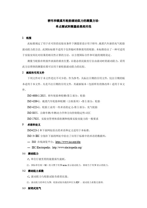
轿车和载重车轮胎滚动阻力的测量方法-单点测试和测量结果相关性1 范围此标准规定了用于在可控的实验室条件下测量原设计用于轿车、载重汽车新的充气轮胎滚动阻力的方法。
此国际标准不适用于仅供临时替换使用的轮胎。
本标准给出了一种可适用于实验室间比对结果的相关性计算的方法,以方便国际合作和可能的规则设定。
测量当轮胎在转鼓外表面的垂直位置,以稳态状况做直行自由滚动时的滚动阻力,采用此方法得到的测量结果可以用于新轮胎滚动阻力的比较。
2 规范性引用文件下列文件对于本文件是比不可少的。
作为参考,凡标注日期的引用文件,仅注日期的版本适用于本文件。
凡是不注日期的引用文件,其最新版本(包括所有的修改单)适用于本文件。
ISO 4000-1:2015,轿车轮胎和轮辋-第1部分:轮胎ISO 4209-1,载重汽车轮胎和轮辋(公制系列)-第1部分:轮胎ISO 4223-1,轮胎工业用一些术语的定义-第1部分:充气轮胎ISO 8855,公路车辆-车辆动力学和方向控制稳定性-词汇ISO 17025,实验室管理体系检测和校准实验室能力的一般要求3 术语和定义ISO4223-1和下面网址给出的术语和定义适用于本标准。
ISO和IEC分别在下面的网址中给出了应用于标准中的术语的数据库:—ISO 在线浏览平台:https:///obp—IEC Electropedia:/3.1滚动阻力F r单位行驶里程的能量损失能耗。
注:国际单位制(SI)的习惯于用N·m/m表示滚动阻力,那相当于用N表示的阻力。
3.2滚动阻力系数C r滚动阻力与轮胎试验负荷的比值。
注:滚动阻力的单位为N,轮胎试验负载的单位为KN 。
滚动阻力系数无量纲。
3.3封闭式充气给轮胎充气,并允许轮胎的气压在运行过程中增加的充气方法。
3.4附加损失除轮胎自身的损失外的单位距离的能量损失(或能量消耗),是由测试设备的转动部件的空气阻力、轴承摩擦力以及其他与测试方法有关的系统损失。
中英文文献翻译-低滚动阻力轮胎
中英文文献翻译-低滚动阻力轮胎附录附录A:LOW ROLLING RESISTANCE TIRES According to the report,80% or more of a car’s fuel energy is wasted by friction and other such losses. 1.5 to 4.5% of total gasoline use could be saved if allreplacement tires in use had low rolling resistance. About 237 million replacement tires are sold in the U.S. each year – none has rolling resistance labeling.1. America’s Fuel Use, Its Impacts,and Opportunities for SavingsThe environmental impacts of America’s gasoline use are profound. With over 160 million passenger cars and light trucks on the road, we burn about 126 billion gallons of gasoline per year. Our fuel use continues to rise about 3% annually, propelled by continued increases in total number of vehicles, rising average distance driven per car, and falling average fuel economy.Today, light-duty vehicles (cars & light trucks) are responsible for about 20% of the nitrogen oxides, 27% of the volatile organic compounds, 51% of the carbon monoxide, and roughly 30% of all the carbon dioxide (the main greenhouse gas) emitted from human activities nationwide. Rising fuel use also has enormous implications for protection of wilderness and public lands (vulnerable to increased exploration), water resources (vulnerable to tanker and pipeline accidents), and national security. So the opportunity to save money and improve environmental quality through fuel use reductions is clear.One of the most promising opportunities for fuel savings across the entire fleet of existing vehicles is to utilize low rollingresistance tires instead of standard replacement models. This change improves the inherent efficiency of the vehicle, automatically saving fuel over the typical 30,000 to 50,000 mile lifetime of a set of tires.This report examines the opportunity for saving gasoline through use of improved tire technology and recommends particular tire models for which our initial test data suggest environmental advantages. Its findings are applicable to government and corporate fleet managers as well as individual tire buyers.2. How Tires Can Reduce Fuel ConsumptionAccording to the National Academy of Sciences, about 80 to 88% of the energy in a vehicle’s gasoline tank is wasted in various thermal, frictional, and standby losses in the engine and exhaust system. This leaves only about 12 to 20% of the potential energy actually converted to vehicle motion. One of the key ways to improve that efficiency is to reduce the rolling resistance of vehicle tires. This is not a measure of a tire’s traction or “grip” on the road surface, but rather simply indicates how easily a tire rolls down the road, minimizing the energy wasted as heat between the tire and the road, within the tire sidewall itself, and between the tire and the rim.Detailed modeling conducted by the National Renewable Energy Laboratory concluded that a 10% reduction in tire rolling resistance should yield fuel savings of about 1 to 2%, depending on driving conditions and vehicle type. According to research for the California Energy Commission, about 1.5 to 4.5% of total gasoline use could be saved if all replacement tires in use had low rollingresistance. This translates roughly into average savings of up to 30 gallons of gasoline savings per vehicle per year, orfrom $2.5 to $7.5 billion worth of national average gasoline savings.As part of their efforts to meet Federal fuel economy standards, automakers routinely specify low rolling resistance tires on their new vehicles. Between 1980 and 1994, the lowest rolling resistance tire models available achieved a 48% reduction in rolling resistance, and have likely continued to improve thereafter. These original equipment (OE) tire models are occasionally available in the replacement tire market, but often only by special order. In general, the tires marketed to the replacement tire market tend to place greater emphasis on longevity and low price, and therefore often have higher rolling resistance than OE tires.Unfortunately both OE and replacement tires lack any sort of rolling resistance labeling currently, so fleet managers and consumers that wish to buy highly energy-efficient tires when their first set of OE tires wear out have been stymied. Even when tire makers claim that particular replacement models are more fuelefficient than others, they do not always use consistent test methods or independent laboratory data to back up those claims. About 237 million replacement tires are sold in the U.S. each year for cars and light trucks, and none of them provides rolling resistance labeling.In 2002, the Energy Foundation funded Ecos Consulting to analyze the tire market, select representative models for rolling resistance testing, and work with Green Seal to recommend particular models that perform well while achieving low rolling resistance.Those findings are being published for the first time in this Choose Green Report. Additional background on EcosConsulting’s key findings can be found in a separate report prepared for the California Energy Commission, available at /doc/81132198.html,/reports/2003- 01-31_600-03-001CRVOL2.PDF.3. Balancing Tire Resistance and Other ConsiderationsThe manufacture of tires, like other industrial processes, involves material extraction and production, as well as energy consumption and the emission of various pollutants. Each of these manufacturing stages impacts the environment in different ways. However, tires, like a number of other consumer products, are actually responsible for more environmental impacts in their use and ultimate disposition than in their manufacturing. They significantly impact the amount of fuel consumed by the vehicle to which they are attached, leading to global warming emissions as well as local and regional air pollution. They create particulate air pollution in the process of wearing, and they can be a significant solid waste problem if not properly recycled.An analysis conducted by Italian tire manufacturer Pirelli (Figure 1) revealed the dominance of tire use in overall life-cycle energy consumption. Fully 82% of the lifecycle energy use occurs from the tire’s contribution to vehicle fuel use, compared to roughly 18% associated with obtaining the raw materials and manufacturing the tire itself. Thus, a tire’s roll ing resistance is likely to be a larger factor in its life-cycle environmental impact than its composition, longevity, or ultimate fate, though those factors merit consideration as well.This report places greatest significance on the measured rolling resistance of tires, followed closely by consideration of the tire’s expected longevity and performance characteristics. A tire with high rolling resistance can cause profound environmentalimpact, even if it capably grips the road and lasts for 80,000 miles. By contrast, a very low ro lling resistance tire may not be worth recommending if its lifetime is unusually short or test data indicate that it provides poor traction.Every tire currently on the market represents a balance between a wide assortment of desired performance characteristics and price (we surveyed tires ranging from $25 to over $200 per tire). Careful balancing of these characteristics can yield not only a high-performing tire, but also one that is better for the environment than others currently available on the market.4.Rating Tire Rolling Resistance and Related FactorsRolling resistance has traditionally been measured through an official Society of Automotive Engineers (SAE) test procedure known as J1269. It measures the force required to roll a tire against a dynamometer at a fixed speed of 50 miles per hour. A newer procedure, SAE J2452, promises improved accuracy by assessing rolling resistance at a variety of speeds, but no independent laboratory currently has the capability to conduct such testing in-house. As a result, all of our testing was conducted at a single independent laboratory according to SAE J1269.The highest and lowest rolling resistance tires we tested differed in efficiency by 60%, indicating that tire choice can have a bigger impact on fuel economy than most people realize. Rolling resistance differences of 20 to 30% are not uncommon among tires of an otherwise similar size, type, and level of performance. This means an individual vehicle could save up to 6% of its gasoline use if it were fitted with very efficient tires, paying for the modest additional cost of low rolling resistance tires in approximately a year of fuel savings. In other words, atypical compact car such as a Ford Focus can improve its mileage from 30 mpg to 32 mpg simply by using lower rolling resistance tires. For a car averaging 15,000 miles per year the fuel savings is about $50 (at $1.50 per gallon).All tires have imprinted information on their sidewalls indicating size, type, load, and speed ratings, as described in Figure 2. The majority of tire models employ a “P” designation for passenger vehicle use, but some bear the “LT” designation for use with light trucks. In general, “P” tires appear to be gaining in popularity relative to “LT” tires of a given size.In addition, the U.S. Department of Transportation requires each manufacturer to grade its tires under the Uniform Tire Quality Grading System (UTQGS) and establish ratings for the following characteristics: tread wear, traction, and temperature resistance. Unfortunately, the ultimate results published for each tire model are less “uniform” than they should be. The government specifies how each test should be conducted and prevents a manufacturer from claiming better performance than measured. However, it does not prevent manufacturers from claiming worse performance than measured. And, curiously enough, many do, primarily to amplify marketing distinctions among their tires at different price points and encourage buyers to move up from a “good” to a “better” or “best” mode l in a particular category.Given the variability of ratings and the number of relevant factors, we have compiled our own composite metrics of performance for assessing tires, including the Federal ratings noted below and a variety of other published data.5.Rolling On to the FutureEfforts to differentiate replacement tires on the basis ofrolling resistance are still in their very early stages. Without data on the rolling resistance of all tire models across a range of sizes, it is impossible to say for sure if the models identified in this report represent the most efficient models or simply a subset of them. For now, consumers and fleet managers can start with the data shown here and request additional information directly from retailers and manufacturers.。
轮胎学习理论(英文版)
CHAPTER 1MECHANICS OF PNEUMATIC TIRESAside from aerodynamic and gravitational forces, all other major forces and moments affecting the motion of a ground vehicle are applied through the running gear–ground contact. An understanding of the basic characteristics of the interaction between the running gear and the ground is, therefore, essential to the study of performance characteristics, ride quality, and handling behavior of ground vehicles.The running gear of a ground vehicle is generally required to fulfill the following functions:•to support the weight of the vehicle•to cushion the vehicle over surface irregularities•to provide sufficient traction for driving and braking•to provide adequate steering control and direction stability.Pneumatic tires can perform these functions effectively and efficiently; thus, they are universally used in road vehicles, and are also widely used in off-road vehicles. The study of the mechanics of pneumatic tires therefore is of fundamental importance to the understanding of the performance and char- acteristics of ground vehicles. Two basic types of problem in the mechanics of tires are of special interest to vehicle engineers. One is the mechanics of tires on hard surfaces, which is essential to the study of the characteristics of road vehicles. The other is the mechanics of tires on deformable surfaces (unprepared terrain), which is of prime importance to the study of off-road vehicle performance.34 MECHANICS OF PNEUMATIC TIRESThe mechanics of tires on hard surfaces is discussed in this chapter, whereas the behavior of tires over unprepared terrain will be discussed in Chapter 2.A pneumatic tire is a flexible structure of the shape of a toroid filled with compressed air. The most important structural element of the tire is the car- cass. It is made up of a number of layers of flexible cords of high modulus of elasticity encased in a matrix of low modulus rubber compounds, as shown in Fig. 1.1. The cords are made of fabrics of natural, synthetic, or metallic composition, and are anchored around the beads made of high tensile strength steel wires. The beads serve as the ‘‘foundations’’ for the carcass and provide adequate seating of the tire on the rim. The ingredients of the rubber com- pounds are selected to provide the tire with specific properties. The rubber compounds for the sidewall are generally required to be highly resistant to fatigue and scuffing, and styrene–butadiene compounds are widely used [1.1].1 The rubber compounds for the tread vary with the type of tire. For instance, for heavy truck tires, the high load intensities necessitate the use of tread compounds with high resistance to abrasion, tearing, and crack growth, and with low hysteresis to reduce internal heat generation and rolling resis- tance. Consequently, natural rubber compounds are widely used for truck tires, although they intrinsically provide lower values of coefficient of road adhesion, particularly on wet surfaces, than various synthetic rubber com- pounds universally used for passenger car and racing car tires [1.1]. For tube- less tires, which have become dominant, a thin layer of rubber with high impermeability to air (such as butyl rubber compounds) is attached to the inner surface of the carcass.The load transmission of a pneumatic tire is analogous to that of a bicycle wheel, where the hub hangs on the spokes from the upper part of the rim, which in turn is supported at its lower part by the ground. For an inflated pneumatic tire, the inflation pressure causes tension to be developed in the cords comprising the carcass. The load applied through the rim of the wheel hangs primarily on the cords in the sidewalls through the beads.The design and construction of the carcass determine, to a great extent, the characteristics of the tire. Among the various design parameters, the ge- ometric dispositions of layers of rubber-coated cords (plies), particularly their directions, play a significant role in the behavior of the tire. The direction of the cords is usually defined by the crown angle, which is the angle between the cord and the circumferential center line of the tire, as shown in Fig. 1.1. When the cords have a low crown angle, the tire will have good cornering characteristics, but a harsh ride. On the other hand, if the cords are at right angle to the centerline of the tread, the tire will be capable of providing a comfortable ride, but poor handling performance.A compromise is adopted in a bias-ply tire, in which the cords extend diagonally across the carcass from bead to bead with a crown angle of ap- 1 Numbers in brackets designate references at the end of the chapter.MECHANICS OF PNEUMATIC TIRES5 Fig. 1.1 Tire construction. (a) Bias-ply tire. (b) Radial-ply tire.6 MECHANICS OF PNEUMATIC TIRESproximately 40°, as shown in Fig. 1.1(a). A bias-ply tire has two plies (for light-load tires) or more (up to 20 plies for heavy-load tires). The cordsin adjacent plies run in opposite directions. Thus, the cords overlap in a diamond-shaped (criss-cross) pattern. In operation, the diagonal plies flex and rub, thus elongating the diamond-shaped elements and the rubber-filler. This flexing action produces a wiping motion between the tread and the road, which is one of the main causes of tire wear and high rolling resistance [1.2, 1.3].The radial-ply tire, on the other hand, is constructed very differently fromthe bias-ply tire. It was first introduced by Michelin in 1948 and has now become dominant for passenger cars and trucks and increasingly for heavy-duty earth-moving machinery. However, the bias-ply tire is still in use inparticular fields, such as cycles, motorcycles, agricultural machinery, and some military equipment. The radial-ply tire has one or more layers of cordsin the carcass extending radially from bead to bead, resulting in a crown angle of 90°, as shown in Fig. 1.1(b). A belt of several layers of cords of high modulus of elasticity (usually steel or other high-strength materials) isfitted under the tread, as shown in Fig. 1.1(b). The cords in the belt are laid at a low crown angle of approximately 20°. The belt is essential to the proper functioning of the radial-ply tire. Without it, a radial-ply carcass can become unstable since the tire periphery may develop into a series of buckles due tothe irregularities in cord spacing when inflated. For passenger car tires, usu-ally there are two radial plies in the carcass made of synthetic material, suchas rayon or polyester, and two plies of steel cords and two plies of cords made of synthetic material, such as nylon, in the belt. For truck tires, usually there is one radial steel ply in the carcass and four steel plies in the belt. For the radial-ply tire, flexing of the carcass involves very little relative movement of the cords forming the belt. In the absence of a wiping motion between the tire and the road, the power dissipation of the radial-ply tire could be as low as 60% of that of the bias-ply tire under similar conditions, and the life of the radial-ply tire could be as long as twice that of the equivalent bias-ply tire [1.3]. For a radial-ply tire, there is a relatively uniform ground pressure over the entire contact area. In contrast, the ground pressure for a bias-ply tire varies greatly from point to point as tread elements passing through the contact area undergo complex localized wiping motion.There are also tires built with belts in the tread on bias-ply construction.This type of tire is usually called the bias-belted tire. The cords in the belt are of materials with a higher modulus of elasticity than those in the bias- plies. The belt provides high rigidity to the tread against distortion, and re- duces tread wear and rolling resistance in comparison with the conventional bias-ply tire. Generally, the bias-belted tire has characteristics midway be- tween those of the bias-ply and the radial-ply tire.In the United States, the Department of Transportation requires tire man-ufacturers to provide information on tire dimensions and ratings on the side-1.1 TIRE FORCES AND MOMENTS7 wall of every tire. For instance, for a tire ‘‘P185 / 70 R14 87S,’’ ‘‘P’’ indicates a passenger car tire; ‘‘185’’ is the nominal width of the cross section in millimeters; ‘‘70’’ is the aspect ratio, which is the ratio of the height of the sidewall to the cross-sectional width; ‘‘R’’ stands for radial-ply tire; ‘‘14’’ is the rim diameter in inches; ‘‘87’’ is a code indicating the maximum load the tire can carry at its maximum rated speed; ‘‘S’’ is a speed rating which in- dicates the maximum speed that the tire can sustain without failure, S 112 mph (180 km/ h), T—118 mph (190 km/ h), H—130 mph (210 km/ h), V— 149 mph (240 km/ h), Z—149 mph (240 km/ h) or more. Traction and tem- perature capabilities are indicated on a scale from A to C, A being the best and C the worst. The traction rating is based on straight-line stopping ability on a wet surface. The temperature rating is an index of the tire’s ability to withstand the heat that high speeds, heavy loads, and hard driving generate. Tread-wear index is an indication of expected tire life. It is rated against a reference tire with an index of 100. For instance, a tread-wear rating of 420 means that the tire should last 4.2 times as long as the reference tire. A tread- wear index of 180 is considered to be quite low and an index of 500, quite high.Although the construction of pneumatic tires differs from one type to an- other, the basic problems involved are not dissimilar. In the following sections, the mechanics fundamental to all types of tire will be discussed. The char- acteristics peculiar to a particular kind of tire will also be described.1.1 TIRE FORCES AND MOMENTSTo describe the characteristics of a tire and the forces and moments acting on it, it is necessary to define an axis system that serves as a reference for the definition of various parameters. One of the commonly used axis systems recommended by the Society of Automotive Engineers is shown in Fig. 1.2 [1.4]. The origin of the axis system is the center of tire contact. The X axis is the intersection of the wheel plane and the ground plane with a positive direction forward. The Z axis is perpendicular to the ground plane with a positive direction downward. The Y axis is in the ground plane, and its di- rection is chosen to make the axis system orthogonal and right hand.There are three forces and three moments acting on the tire from theground. Tractive force (or longitudinal force) Fx is the component in the Xdirection of the resultant force exerted on the tire by the road. Lateral forceFy is the component in the Y direction, and normal force Fzis the componentin the Z direction. Overturning moment Mx is the moment about the X axisexerted on the tire by the road. Rolling resistance moment My is the momentabout the Y axis, and aligning torque Mz is the moment about the Z axis.With this axis system, many performance parameters of the tire can be conveniently defined. For instance, the longitudinal shift of the center of nor- mal pressure is determined by the ratio of the rolling resistance moment to8 MECHANICS OF PNEUMATIC TIRESFig. 1.2 Tire axis system.the normal load. The lateral shift of the center of normal pressure is defined by the ratio of the overturning moment to the normal load. The integration of longitudinal shear stresses over the entire contact patch represents the trac- tive or braking force. A driving torque about the axis of rotation of the tire produces a force for accelerating the vehicle, and a braking torque produces a force for decelerating the vehicle.There are two important angles associated with a rolling tire: the slip angle and the camber angle. Slip angle αis the angle formed between the direction of wheel travel and the line of intersection of the wheel plane with the road surface. Camber angle γis the angle formed between the XZ plane and the wheel plane. The lateral force at the tire–ground contact patch is a function of both the slip angle and the camber angle.1.2 ROLLING RESISTANCE OF TIRESThe rolling resistance of tires on hard surfaces is primarily caused by the hysteresis in tire materials due to the deflection of the carcass while rolling. Friction between the tire and the road caused by sliding, the resistance due to air circulating inside the tire, and the fan effect of the rotating tire on the1.2 ROLLING RESISTANCE OF TIRES9 surrounding air also contribute to the rolling resistance of the tire, but they are of secondary importance. Available experimental results give a breakdown of tire losses in the speed range 128–152 km/ h (80–95 mph) as 90–95% due to internal hysteresis losses in the tire, 2–10% due to friction between the tire and the ground, and 1.5–3.5% due to air resistance [1.5, 1.6]. Of the total energy losses within the tire structure, it is found that for a radial truck tire, hysteresis in the tread region, including the belt, contributes 73%, the sidewall 13%, the region between the tread and the sidewall, commonly known as the shoulder region, 12%, and the beads 2%.When a tire is rolling, the carcass is deflected in the area of ground contact. As a result of tire distortion, the normal pressure in the leading half of the contact patch is higher than that in the trailing half. The center of normal pressure is shifted in the direction of rolling. This shift produces a moment about the axis of rotation of the tire, which is the rolling resistance moment. In a free-rolling tire, the applied wheel torque is zero; therefore, a horizontal force at the tire–ground contact patch must exist to maintain equilibrium. This resultant horizontal force is generally known as the rolling resistance. The ratio of the rolling resistance to the normal load on the tire is defined as the coefficient of rolling resistance.A number of factors affect the rolling resistance of a pneumatic tire. They include the structure of the tire (construction and materials) and its operating conditions (surface conditions, inflation pressure, speed, temperature, etc.). Tire construction has a significant influence on its rolling resistance. Figure 1.3 shows the rolling resistance coefficient at various speeds of a range of bias-ply and radial-ply passenger car tires at rated loads and inflation pres- sures on a smooth road [1.7]. The difference in rolling resistance coefficient between a bias-ply and a radial-ply truck tire of the same size under rated conditions is shown in Fig. 1.4 [1.8]. Thicker treads and sidewalls and an increased number of carcass plies tend to increase the rolling resistance be- cause of greater hysteresis losses. Tires made of synthetic rubber compounds generally have higher rolling resistance than those made of natural rubber. Tires made of butyl rubber compounds, which are shown to have better trac- tion and roadholding properties, have an even higher rolling resistance than those made of conventional synthetic rubber. It is found that the rolling re- sistance of tires with tread made of synthetic rubber compounds and that made of butyl rubber compounds are approximately 1.06 and 1.35 times that made of natural rubber compounds, respectively [1.9].Surface conditions also affect the rolling resistance. On hard, smooth sur- faces, the rolling resistance is considerably lower than that on a rough road. On wet surfaces, a higher rolling resistance than on dry surfaces is usually observed. Figure 1.5 shows a comparison of the rolling resistance of passen- ger car tires over six road surfaces with different textures, ranging from pol- ished concrete to coarse asphalt [1.10]. The profiles of these six surfaces are shown in Fig. 1.6. It can be seen that on the asphalt surface with coarse seal- coat (surface no. 6) the rolling resistance is 33% higher than that on a new10 MECHANICS OF PNEUMATIC TIRESFig. 1.3 Variation of rolling resistance coefficient of radial-ply and bias-ply car tires with speed on a smooth, flat road surface under rated load and inflation pressure. (Reproduced with permission from Automotive Handbook, 2nd edition, Robert Bosch GmbH, Germany.)Fig. 1.4 Variation of rolling resistance coefficient of radial-ply and bias-ply truck tires with speed under rated load and inflation pressure. (Reproduced with permission from reference 1.8.)1.2 ROLLING RESISTANCE OF TIRES11Fig. 1.5 Variation of tire rolling resistance with pavement surface texture. (Repro- duced with permission of the Society of Automotive Engineers from reference 1.10.)Fig. 1.6 Texture of various types of pavement surface. (Reproduced with permission of the Society of Automotive Engineers from reference 1.10.)12 MECHANICS OF PNEUMATIC TIRESconcrete surface (surface no. 2), while on the polished concrete (surface no.1), it shows a 12% reduction in comparison with that on the new concrete surface.Inflation pressure affects the flexibility of the tire. Depending on the de- formability of the ground, the inflation pressure affects the rolling resistance of the tire in different manners. On hard surfaces, the rolling resistance gen- erally decreases with the increase in inflation pressure. This is because, with higher inflation pressure, the deflection of the tire decreases, with consequent lower hysteresis losses. Figure 1.7 shows the effects of inflation pressure on the rolling resistance of a radial-ply tire (GR78-15), a bias-ply tire, and a bias-belted tire (both G78-15) under various normal loads, expressed in terms of the percentage of the rated load at an inflation pressure of 165 kPa (24 psi) [1.11]. The results were obtained with the inflation pressure being reg- ulated, that is, the pressure was maintained at a specific level throughout the tests. It can be seen that inflation pressure has a much more significant effect on the rolling resistance of the bias and bias-belted tires than the radial-ply tire. On deformable surfaces, such as sand, high inflation pressure results in increased ground penetration work, and therefore higher rolling resistance, as shown in Fig. 1.8 [1.12]. Conversely, lower inflation pressure, while decreas- ing ground penetration, increases the deflection of the tire and hence internal hysteresis losses. Therefore, an optimum inflation pressure exists for a par- ticular tire on a given deformable surface, which minimizes the sum of ground penetration work and internal losses of the tire.Inflation pressure not only affects the rolling resistance, but also the tread wear of a tire. Figure 1.9 shows the effects of inflation pressure on tread wearFig. 1.7 Variation of rolling resistance of radial-ply, bias-belted, and bias-ply car tires with load and inflation pressure. (Reproduced with permission of the Society of Au- tomotive Engineers from reference 1.11.)1.2 ROLLING RESISTANCE OF TIRES13Fig. 1.8 Variation of rolling resistance coefficient with inflation pressure of tires on various surfaces. (Reproduced with permission from reference 1.12.)Fig. 1.9 Variation of shoulder-crown wear with inflation pressure for radial-ply, bias- ply, and bias-belted car tires. (Reproduced with permission of the Society of Auto- motive Engineers from reference 1.11.)14 MECHANICS OF PNEUMATIC TIRESof a radial-ply, a bias-ply, and a bias-belted tire [1.11]. The wear rate at 165 kPa (24 psi) is used as a reference for comparison. It can be seen that the effects of inflation pressure on tread wear are more significant for the bias- ply and bias-belted tire than the radial-ply tire.Rolling resistance is also affected by driving speed because of the increase of work in deforming the tire and of vibrations in the tire structure with the increase in speed. The effects of speed on the rolling resistance of bias-ply and radial-ply passenger car and truck tires are illustrated in Figs. 1.3 and 1.4, respectively. For a given tire under a particular operating condition, there exists a threshold speed above which the phenomenon popularly known as standing waves will be observed, as shown in Fig. 1.10. The approximatevalue of the threshold speed Vth may be determined by the expression Vth\/F t / p t, where F t is the circumferential tension in the tire and p t is the density of tread material per unit area [1.13]. Standing waves are formed because, owing to high speed, the tire tread does not recover immediately from dis- tortion originating from tire deflection after it leaves the contact surface, and the residual deformation initiates a wave. The amplitude of the wave is the greatest immediately on leaving the ground, and is damped out in an expo- nential manner around the circumference of the tire. The formation of the standing wave greatly increases energy losses, which in turn cause consid- erable heat generation that could lead to tire failure. This places an upper limit on the safe operating speed of tires.Operating temperature, tire diameter, and tractive force also have effects on the rolling resistance of a tire. Tire temperature affects the rolling resis- tance in two ways: one is by changing the temperature of the air in the tire cavity, and thereby changing the operating inflation pressure; and the other is by changing the stiffness and hysteresis of the rubber compounds. Figure 1.11 shows the dependence of the rolling resistance on the internal tire temperature for an automobile tire [1.5]. The variation of rolling resistance coefficient with shoulder temperature of a radial-ply passenger car tire is shown in Fig.1.12 [1.14]. It can be seen that the rolling resistance at a shoulder temperature of 10°C is approximately2.3 times that at 60°C for the tire examined. It is also found that the shoulder temperature of the tire, and not the ambientFig. 1.10 Formation of standing waves ofa tire at high speeds.1.2 ROLLING RESISTANCE OF TIRES15Fig. 1.11 Effect of internal temperature on rolling resistance coefficient of a car tire. (Reproduced with permission of the Council of the Institution of Mechanical Engineers from reference 1.5.)temperature, is a basic determining factor of the tire rolling resistance coef- ficient. The effect of tire diameter on the coefficient of rolling resistance is shown in Fig. 1.13 [1.12]. It can be seen that the effect of tire diameter is negligible on hard surfaces (concrete), but is considerable on deformable or soft ground. Figure 1.14 shows the effect of the braking and tractive effort on the rolling resistance [1.6].Fig. 1.12 Variation of rolling resistance coefficient with shoulder temperature for a car tire P195 / 75R14. (Reproduced with permission of the Society of Automotive En- gineers from reference 1.14.)16 MECHANICS OF PNEUMATIC TIRESFig. 1.13 Effect of tire diameter onrolling resistance coefficient on var-ious surfaces. (Reproduced with per-mission from reference 1.12.) When considering the effects of material, construction, and design para- meters of tires on rolling resistance, it is necessary to have a proper perspec- tive of the energy losses in the tire and the characteristics of the tire–vehicle system as a whole. Although it is desirable to keep the rolling resistance as low as possible, it should be judged against other performance parameters, such as tire endurance and life, traction, cornering properties, cushioning ef-Fig. 1.14 Effect of tractive and braking effort on rolling resistance coefficient of a car tire. (Reproduced with permission from Mechanics of Pneumatic Tires, edited by S.K. Clark, Monograph 122, National Bureau of Standards, 1971.)1.2 ROLLING RESISTANCE OF TIRES17 fect, cost, etc. For instance, from the standpoint of rolling resistance, synthetic rubber compounds are less favorable than natural rubber compounds, yet be- cause of significant advantages in cost, tread life, wet-road grip, and tire squeal, they have virtually displaced natural rubber compounds from passen- ger car tires, particularly for treads. For high-performance vehicles, there may be some advantage for using butyl rubber tires because of the marked gains in traction, roadholding, silence, and comfort, in spite of their poor hysteresis characteristics [1.5].The complex relationships between the design and operational parameters of the tire and its rolling resistance make it extremely difficult, if not impos- sible, to develop an analytic method for predicting the rolling resistance. The determination of the rolling resistance, therefore, relies almost entirely on experiments. To provide a uniform basis for collecting experimental data, the Society of Automotive Engineers recommends rolling resistance measurement procedures for various types of tire on different surfaces, which may be found in the SAE Handbook.Based on experimental results, many empirical formulas have been pro- posed for calculating the rolling resistance of tires on hard surfaces. For in- stance, based on the experimental data shown in Fig. 1.3, for radial-ply passenger car tires under rated loads and inflation pressures on a smooth road,the relationship between rolling resistance coefficient ƒr and speed V (up to150 km/ h or 93 mph) may be expressed byƒr0.0136 + 0.40 × 10 7 V 2(1.1) and for bias-ply passenger car tires,ƒr0.0169 + 0.19 × 10 6 V 2(1.2)where V is in km/ h.Based on the experimental data shown in Fig. 1.4, for the radial-ply truck tire under rated load and inflation pressure, the relationship between the roll-ing resistance coefficient ƒr and speed V (up to 100 km/ h or 62 mph) maybe described byƒr0.006 + 0.23 × 10 6 V 2(1.3) and for the bias-ply truck tire,ƒr0.007 + 0.45 × 10 6 V 2(1.4)where V is in km/ h.The rolling resistance coefficient of truck tires is usually lower than that of passenger car tires on road surfaces. This is primarily due to the higher)( )18MECHANICS OF PNEUMATIC TIRESinflation pressure used in truck tires (typically 620–827 kPa or 90–120 psi as opposed to 193–248 kPa or 28–36 psi for passenger car tires).In preliminary performance calculations, the effect of speed may be ig- nored, and the average value of ƒr for a particular operating condition may be used. The average values of ƒr for various types of tire over different surfaces are summarized in Table 1.1.1.3 TRACTIVE (BRAKING) EFFORT AND LONGITUDINAL SLIP (SKID)When a driving torque is applied to a pneumatic tire, a tractive force is developed at the tire–ground contact patch, as shown in Fig. 1.15 [1.6]. At the same time, the tire tread in front of and within the contact patch is sub- jected to compression. A corresponding shear deformation of the sidewall of the tire is also developed.As tread elements are compressed before entering the contact region, the distance that the tire travels when subject to a driving torque will be less than that in free rolling. This phenomenon is usually referred to as longitudinal slip. The longitudinal slip of the vehicle running gear, when a driving torque is applied, is usually defined byi(1 V× 100%1r e × 100% (1.5)r wrwhere V is the linear speed of the tire center, w is the angular speed of the tire, r is the rolling radius of the free-rolling tire, and r e is the effective rolling radius of the tire, which is the ratio of the linear speed of the tire center to the angular speed of the tire.TABLE 1.1 Coefficient of Rolling Resistance Road Surface Coefficient of Rolling ResistanceCar tiresConcrete, asphalt 0.013 Rolled gravel 0.02 Tarmacadam 0.025 Unpaved road 0.05 Field 0.1–0.35 Truck tiresConcrete, asphalt0.006–0.01Source: Automotive Handbook, 4th edition, Bosch, 1996. (Reproduced with permission of Robert Bosch GmbH, Germany.)。
轮胎滚动阻力精确测试方法研究

轮胎滚动阻力精确测试方法研究欧阳爱国;毕朋飞;肖文龙;陈齐平;欧阳玉平【摘要】针对目前常用的轮胎滚动阻力室内测试方法(测力法、滑行法、反拖法等)与室外实际道路得出的轮胎滚动阻力对比相差较大的问题,通过比较分析各种现有测试方法的优缺点,提出一种利用单滚筒底盘测功机来测量轮胎滚动阻力的方法.为提高测试准确度,在实验开始前依据转鼓自身滑行消除单滚筒台架的内阻,在单滚筒底盘测功机的无加载滑行和二次加载滑行实验基础之上建立相应的数学模型,得出汽车和测功机总的惯性质量,具有操作简单、准确度高等优点.【期刊名称】《中国测试》【年(卷),期】2015(041)012【总页数】4页(P1-4)【关键词】轮胎滚动阻力;单滚筒底盘测功机;加载;滑行方法;台架内阻【作者】欧阳爱国;毕朋飞;肖文龙;陈齐平;欧阳玉平【作者单位】华东交通大学机电工程学院,江西南昌330013;华东交通大学机电工程学院,江西南昌330013;华东交通大学机电工程学院,江西南昌330013;华东交通大学机电工程学院,江西南昌330013;华东交通大学机电工程学院,江西南昌330013【正文语种】中文0 引言人类生存活动对环境的影响越来越引起社会关注,减少燃料的损耗、降低汽车的尾气排放是防止大气污染的重要举措。
试验数据表明:对于乘用车来说约有3.4%~6.6%的能源都消耗在轮胎的滚动阻力上,当轮胎的滚动阻力减少5%左右时,汽车能源消耗将减少1%[1]。
因此,汽车轮胎滚动阻力的准确测量不仅影响到汽车动力性检测的准确性和汽车技术等级的评定,而且会影响到汽车能源消耗量。
滚动阻力的形成是因为车轮滚动时,车轮与道路表面都将发生形变,此时轮胎与道路表面材料之间的内摩擦以及轮胎表面与道路表面间的摩擦在轮胎表面形成了滚动阻力[2]。
轮胎滚动阻力的影响因素主要有:轮胎气压、汽车行驶速度、路面状况、轮胎表面制造材料等。
因此室外测量的影响因素多,极为不可靠,目前对轮胎滚动阻力的测量主要是在实验室内的滚动阻力实验机上进行[3]。
汽车轮胎滚动阻力试验机理和试验方法
汽车轮胎滚动阻力试验机理和试验方法
杨风海;盛保信;杨浩;吕斌川
【期刊名称】《现代橡胶技术》
【年(卷),期】2003(029)002
【摘要】以美国MTS RW860轮胎性能试验机试验机理为基础,介绍汽车轮胎滚动阻力的试验原理,试验方法及其试验结果。
【总页数】5页(P35-39)
【作者】杨风海;盛保信;杨浩;吕斌川
【作者单位】曙光橡胶工业研究设计院,广西桂林54104
【正文语种】中文
【中图分类】U463.341
【相关文献】
1.SUV汽车轮胎磨耗试验方法研究 [J], 王星亮;刘国栋;宋晋
2.欧洲汽车轮胎滚动阻力及噪声测量方法 [J], 李玲;佘翔;杨小峰
3.双前桥转向汽车轮胎强化磨损试验方法的研究 [J], 程源
4.电动汽车轮胎滚动阻力与噪声协调设计及产品开发 [J], 殷瑞婧;雍占福;冯启章;王昊;危银涛
5.国内外轮胎滚动阻力试验方法及影响因素分析 [J], 王阳;张子鹏;朱其文;魏晓辰因版权原因,仅展示原文概要,查看原文内容请购买。
AVL CRUISE在轮胎滚动阻力能量消耗研究中的应用
AVL CRUISE在轮胎滚动阻力能量消耗研究中的应用
何润;翟克娇
【期刊名称】《汽车制造业》
【年(卷),期】2018(000)005
【摘要】为了研究轮胎滚动阻力对燃油经济性的影响,本文在能量流分析理论基础上,推导建立了轮胎滚动阻力能量消耗模型,在滚动阻力测试方面,应用了一种可以一次完成在不同车速、载荷及充气胎压下测试28个工况点的方法。
对比传统AVL Cruise油耗分析模型,计算结果符合度较高,可以应用于整车能量流系统分析工作中,在评价轮胎滚动阻力改善效果方面有重要价值。
【总页数】4页(P38-41)
【作者】何润;翟克娇
【作者单位】上汽通用五菱汽车股份有限公司;上汽通用五菱汽车股份有限公司【正文语种】中文
【中图分类】U467.1
【相关文献】
1.基于AVL-CRUISE仿真在金龙某客车转鼓与道路油耗分析中的应用 [J], 于文涛
2.AVL-Cruise仿真在商用车油耗分析中的应用 [J], 怀自力;刘闪闪;李小坚
3.AVL Cruise和AVL Driver联合虚拟仿真在整车性能开发和评价方面的应用 [J], 张明凯
4.AVL_CRUISE软件在汽车仿真教学中的应用研究 [J], 陆昌年
5.AVL-cruise在商用车速比匹配中的应用 [J], 张玮龙;张文艺;杨淼
因版权原因,仅展示原文概要,查看原文内容请购买。
- 1、下载文档前请自行甄别文档内容的完整性,平台不提供额外的编辑、内容补充、找答案等附加服务。
- 2、"仅部分预览"的文档,不可在线预览部分如存在完整性等问题,可反馈申请退款(可完整预览的文档不适用该条件!)。
- 3、如文档侵犯您的权益,请联系客服反馈,我们会尽快为您处理(人工客服工作时间:9:00-18:30)。
Study of automobile tire rolling resistance and testing technology Human activities on the ecological damage to the environment has become a global problem, to reduce fuel consumption, reduce automobile exhaust emissions is energy conservation, prevention of air pollution in an important measure. Vehicle energy consumption is closely related with the tire rolling resistance. On cars or light trucks, the 3.4% ~ 6.6% of fuel consumption used to overcome rolling resistance tires; of loaded radial truck tire with the car example, 12.4% ~ 14.5% of fuel consumption to overcome the rolling resistance tires . Tire rolling resistance by 10%, fuel-efficient cars will be 1.2 percent, 4 percent savings trucks. To this end,the tire manufacturers have at home and abroad to develop new low-power tires to reduce rolling resistance, saving fuel.Automobile tires in the rolling process, the total vehicle rolling resistance accounts for about 20% of the resistance, if reduced by 10% per tire rolling resistance, lower 2% ~ 3% of fuel, then rolling resistance tires to enhance the level of control of vehicle contribution to fuel economy will be significant, but also in a wide range can be achieved. Therefore, how to effectively control the tire's rolling resistance is the industry facing a key issue. This article will explore the various angles and analysis as well as tire rolling resistance testing technology.I. SummaryIn the tire rolling process, the cycle of changes in the stress and strain lead to energy loss, the formation of tire rolling resistance, also known as the tire hysteresis energy loss. Studies have shown that to overcome tire rolling resistance on fuel consumption of the general accounting for the total fuel consumption of motor vehicles more than 10%. Reduce rolling resistance tires can reduce vehicle energy consumption, so that the car farther away from efficient. Tire rolling resistance is the overall energy consumption of material, equivalent to the tire rolling units of energy loss from the rolling units in addition to its distance, the dimensionless N • m / m, although its equivalent to the dimensionless force, but from the point of view of energy analysis and understanding more convenient and reasonable.Through the measurement of rolling resistance tires can study the best section. However, the results of lab experiments can only make a comparison, the final road test should be used as the basis of the results.Second, research the history ofAs early as age 60 in the 20th century, Beijing Research and Design Institute of Rubber Industry in turn on the drum machine and measured the wire cotton tire cord tire power loss, also measured on the road when the vehicle speed steady traction resistance. At that time, due to restrictions on the use of equipment, the pilot is in its early exploratory phase of long-term. Since the mid-80s, with the accelerated development of China's tire needs, a small number of tire manufacturers from the United States, Japan and Germany with the introduction of the rolling resistance of the switch position test tire drum testing machine, combined with the development of a new type of radial tire and the analysis of foreign samples a number of tire rolling resistance tires test.Inspection. 70s from the 20th century in the United States, Japan and Europe, such as the economically developed countries, in order to solve energy shortages and the deterioration of environmental quality issues and the rolling resistance tires for a large number of experiments and research work. At the same time, tire rolling resistance testing technologies have also made remarkable progress. Beginning in 2004, the U.S. National Research Center on the control of rolling resistance tires to start a new round of extensive research. In 2007, the European Rubber Manufacturers Association also made to the EU to control the level of rolling resistance of the recommendations. Therefore, China will also face the control of rolling resistance.Third, testing technologyAt present, China has established a laboratory test-based, supplemented by the direction of the outdoor experiment. Steady-state conditions in the interior that is a constant load and speed, the tires when driving to reach thermal equilibrium Tire rolling resistance measurement method of standardization has been achieved.Preliminary results show that the simulation of the city of tire rolling resistance condition than under the conditions of steady-state rolling resistance by 26% ~ 47% of the difference between the two aroused people's interest in the emergence of a simulation of various operating conditions of automobile tires non-steady-state test. But so far did not see a unified standard test methods or test protocols. Carried out in the outdoor tire rolling resistance test methods are mainly trailer Act, taxiways and three kinds of torque method, in which a wider application of the trailer Act.Fourth, laboratory equipmentLaboratory test equipment, through decades of effort, has appeared in various types of tire rolling resistance testing machine. Their roads in accordance with the form of simulation points, and to have a steel drum two broad categories. Strip-type test machine to simulate the continuous flat surface, is very expensive test equipment tires. At present, it is the most widely to drum testing machine, in particular, a diameter of 1.7 meters to the drum. These test equipment measuring tire rolling resistance by way of points, and measuring method, torque law, power law and reduce the rate of four kinds of law. The use of existing equipment to load and torque of law are most welcome. In the past two decades, the accuracy of test equipment greatly enhanced to reduce the double measurement error, and has formed a set of test data to ensure the repeatability of the equipment necessary for accuracy. Has the full realization of China's current industrial production equipment is Jiurong Tianjin rolling resistance testing machine, is divided into car and truck tire with two types of tires, and its accuracy in line with the requirements of ISO. As the outdoor test line tire rolling resistance of non-standard test, the test equipment they use is not changed. Association for the Study of the British automobile industry with the use of the pilot housing trailers, all kinds of tires for air resistance in the same test under the conditions created.V. Test Methods1. Indoor and outdoor test testIndoor and outdoor test test test is based on the distinction between the two types of tire place test method. Indoor test of tire rolling resistance testing machine were conducted, and its experimental conditions, although the Department of simulated conditions of use but can be under control, so that good reproducibility of experimental data. Outdoor test rolling resistance tires are used on test vehicles on the road completed, it is true although the experimental conditions, but susceptible to external factors, pilot error, and therefore tire rolling resistance test to test the main indoor and outdoor test Des.2. Steady-state conditions and non-steady-state conditionsSteady-state conditions in the constant refers to the tire load and speed, and traveling in the tire to reach thermal equilibrium when measuring rolling resistance; non-steady-state conditions, it means the tire change with time in the load and speed, and tire temperature in the process of moving measuring rolling resistance. Of course, the tires in the car on the non-steady-state condition is varied. To the total points, tire condition of the car has the city,the suburbs of the car and coach on. However, a breakdown, and another empty, heavy vehicles, drive, driven, acceleration, deceleration, taxiways, brake, turn, etc. and combinations there of. Typical working condition of the tires as the standard test of non-steady-state conditions, needs to be done to investigate and test a large number of research work. So whether it is the latest ISO 18164 or the existing SAEJ 1269, they were under steady-state conditions. In addition, SAEJ 2452 slowdown is a complex experiment, the experimental conditions than under the uniform steady-state movement is much more complicated, but it is not completely under non-steady-state experiment. As can accurately predict tire rolling resistance is uniform or slowdown, more tests need to be verified, such comparison tests being investigated. However, the tire manufacturer's tire rolling resistance testing machine mostly for the use of steady-state conditions, if used for non-steady-state conditions by the test needs Plus many new features, testing may be a substantial increase in cost.First of all, to deal with the choice of tires to test full consideration, such as the representativeness of the sample, the tire size, type, rated speed, the original production equipment and the type of wheel rim, as well as the technological level of producers and industry status.Secondly, the performance evaluation of the establishment of test methods. Is not any test method can be used to evaluate the performance level, especially the study of test methods, and therefore take into account the actual tire, the combination of existing technology and the means test, set up in line with the experimental detection conditions.Third, laboratory equipment to ensure precision and accuracy of the equipment of the establishment of standards to ensure that test reproducibility and repeatability, such as samples of the same specifications of the rolling resistance tires are consistent and repeatable, with the control tire for the different experiments comparison.Fourth, the establishment of quality control procedures to ensure that the different rolling resistance testing machine test results are consistent and repeatable, the data in these experiments should also include information such as equipment.Fifth, repeat the same tire test, test results are consistent and repeatable.Sixth, tire prices and the relationship between the dynamic resistance.Seventh, most importantly, in the protection of national industries and safeguard the environment and conserve fuel, to resist the flow of low-quality tires to enter the market, the need for serious thinking.A lot of tests in measuring very small load rolling resistance tire rolling resistance is measured the basic characteristics of the tire positioning accuracy, therefore, control precision and accuracy requirements and other equipment is key. According to many years of experience confirm the accuracy of test equipment requirements is necessary, otherwise the test data can not be guaranteed to reach the standards of repeatability and comparability.Lower rolling resistance tires can significantly save energy and protect the environment, with considerable economic and social benefits. Under the conditions of typical use of the tire rolling resistance and fuel consumption the relationship between the steady-state conditions with non-steady-state conditions compared with the torque method, power law and measured by the speed difference in rolling resistance tires will be The next step of our research objectives.Should be established and planned research projects, and used to determine the appropriate control of the rolling resistance or grade; from different points of view to promote and strengthen the grasp of the concept of rolling resistance and applications.探讨汽车轮胎滚动阻力以及测试技术人类活动对生态环境的破坏已成为全球性问题,减少燃料消耗、降低汽车尾气排放量是节约能源、防止大气污染的重要措施。
